ADC Telecommunications PSM0804A FlexWave™ Prism - Cellular 40 Watt User Manual 2
ADC Telecommunications Inc FlexWave™ Prism - Cellular 40 Watt Users Manual 2
Contents
- 1. Users Manual 1
- 2. Users Manual 2
- 3. Users Manual 3
- 4. Users Manual 4
Users Manual 2
Using t he Prism EMS
FlexWave Prism Elem ent Managem ent Syst em 7.1 User Manual Page 45
ADCP- 77- 1 77 • Issue 1 • July 2011 © 2011 ADC Telecom m unicat ions, I nc.
Viewing Alarm Details
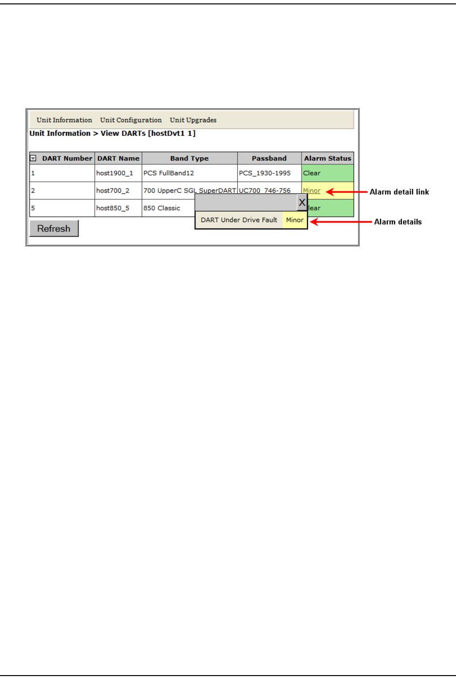
I n m any inst ances, a page will have an Alarm Status colum n, which indicates
whet her an alarm is act ive. I f an alarm is active, t here will be a Minor or Major link
( as shown in Figure 19) t hat you click t o open a dialog t hat defines the act ive
alarm . The background color of the Alarm Status cell also indicates t he alarm level.
Figure 19. Alarm Link
For inform ation on the Alarm indicator in the Syst em Tree, see “ Syst em Tree” on
page 41.
How t o Use the EMS Graphical User I nter face
Page 46 FlexWave Prism Elem ent Managem ent Syst em 7.1 User Manual
© 2011 ADC Telecommunications, Inc ADCP- 77-177 • I ssue 1 • July 2011
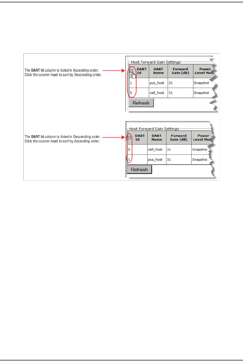
Sorting Tables
You can change t he order of a t able’s content s by applying an alphanum eric sort
on a colum n ( see Figure 20). To toggle a colum n by ascending or descending
order, click in t he colum n heading.
Figure 20. Sorting Tables in the GUI
Using t he Prism EMS
FlexWave Prism Elem ent Managem ent Syst em 7.1 User Manual Page 47
ADCP- 77- 1 77 • Issue 1 • July 2011 © 2011 ADC Telecom m unicat ions, I nc.
FOLLOWING THE PROCEDURES IN THIS DOCUMENT
This sect ion tells you how to use this docum ent to use the FlexWave Prism EMS t o
configure and m anage Prism devices.
Starting a Procedure
All procedures in this docum ent assum e t hat you have already logged in to the
EMS as described in “Access t he EMS” on page 57.
Modifying Parameters
I n general, t he procedures in this docum ent end by having you click OK or Apply t o
accept changes or input .
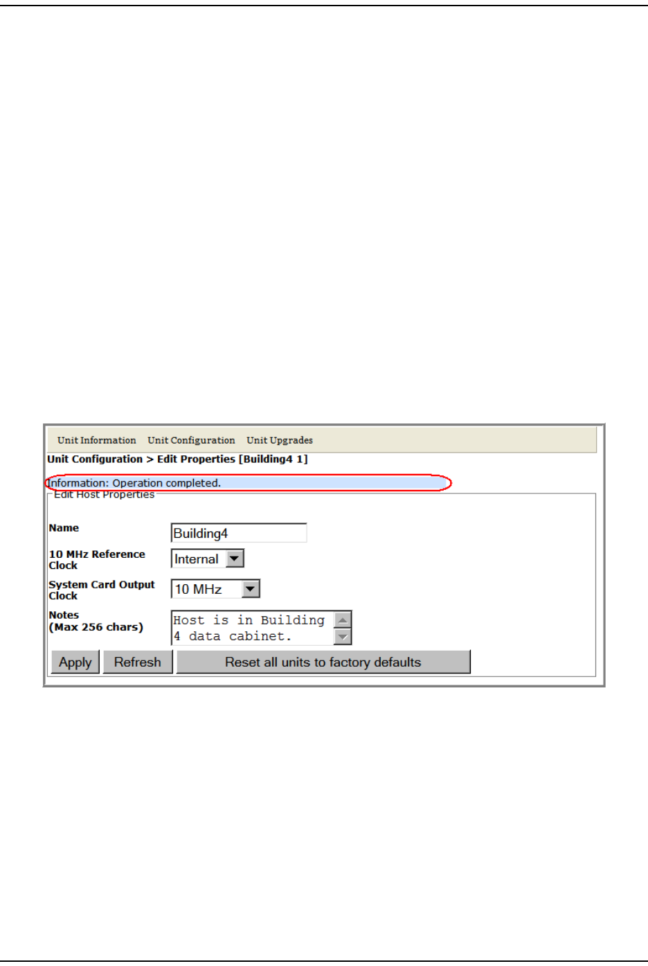
When an operat ion com plet es, an Operation completed m essage displays, such as t he
one shown in Figure 21. I f an error m essage displays, follow t he screen prom pts.
You can click Refresh to updat e the data being shown.
Figure 21. Operation Completed Message

Following the Procedures in t his Docum ent
Page 48 FlexWave Pr ism Elem ent Managem ent System 7.1 User Manual
© 2011 ADC Telecommunications, Inc ADCP- 77-177 • I ssue 1 • July 2011
Selecting Menu Items
I n the Prism user docum entat ion, when a procedure requires t hat you select a
sequence of m enu item s, a right- angle sym bol separate t he item s. For exam ple,
in the following graphic, “ click Users > Manage Users” indicat es that in the Syst em
Menu bar you select Users, and then in the Users list , select Manage Users.
Using t he Prism EMS
FlexWave Prism Elem ent Managem ent Syst em 7.1 User Manual Page 49
ADCP- 77- 1 77 • Issue 1 • July 2011 © 2011 ADC Telecom m unicat ions, I nc.
USING THE HELP EMBEDDED IN THE GUI
The following sect ions t ell you how top access and use the em bedded Prism Help
m odule.
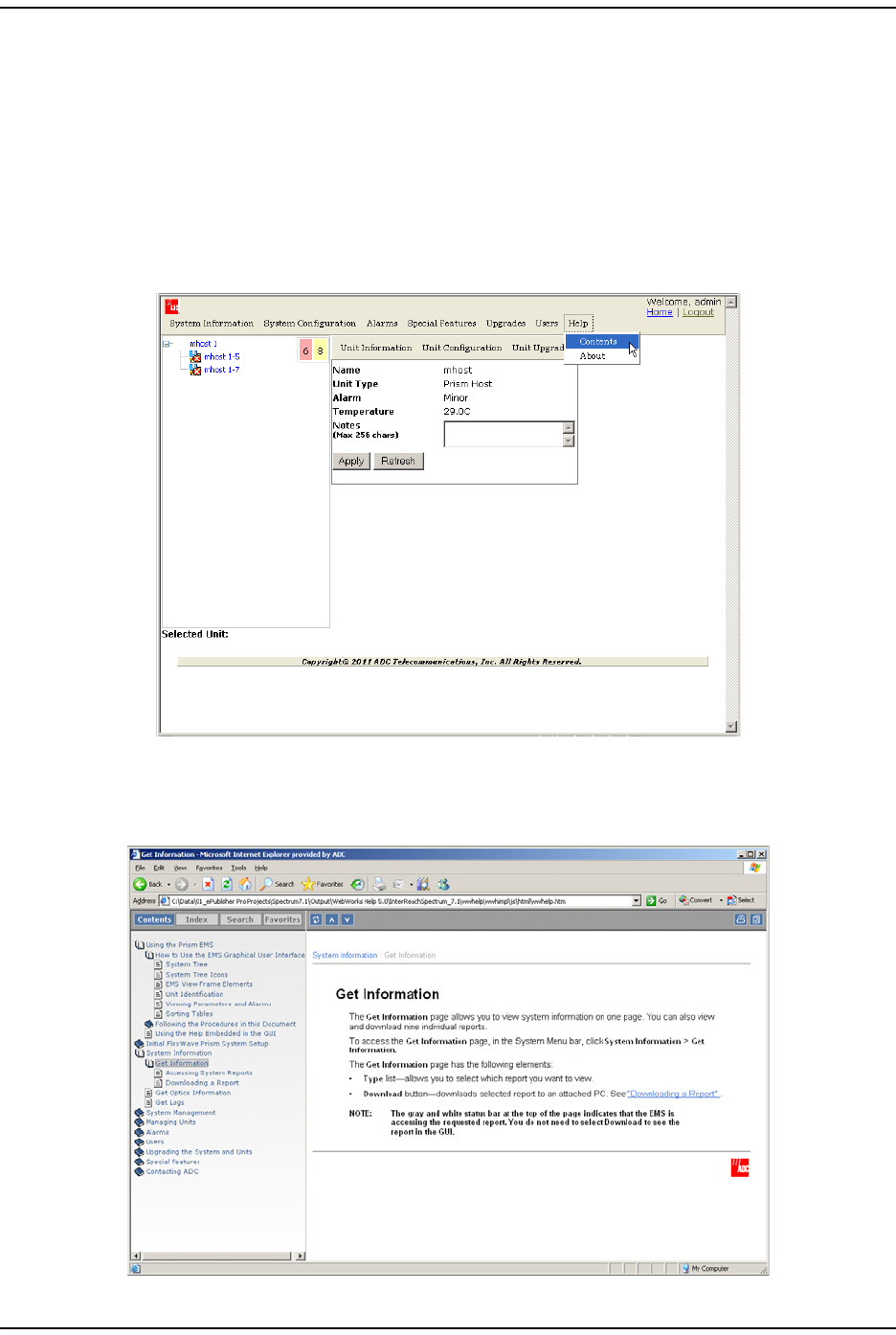
Accessing Help
I n t he Orient at ion Links, click Help > Contents.
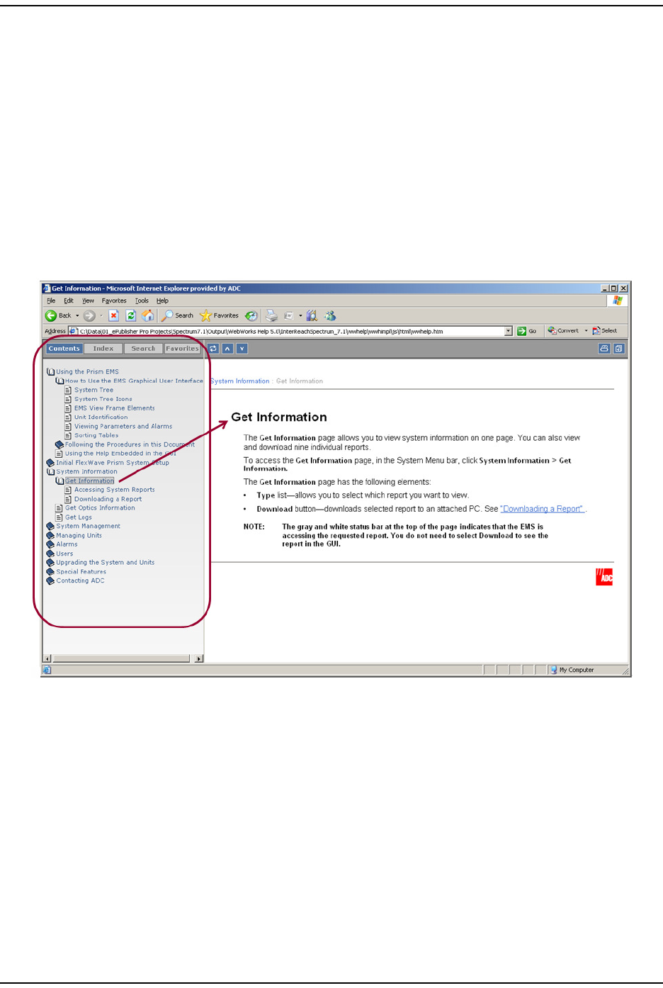
Prism Help is context sensitive, which m eans that t he Help topic that opens will
pertain t o t he current view in t he EMS View Fram e. I n t he following exam ple,
the Help Topic for the Get Information page has opened.
Using t he Help Em bedded in the GUI
Page 50 FlexWave Pr ism Elem ent Managem ent System 7.1 User Manual
© 2011 ADC Telecommunications, Inc ADCP- 77-177 • I ssue 1 • July 2011
Navigating Help
The Help Module is designed like a book to m ake it easy to navigate.
Using the Contents Tab
The default view opens with t he Contents navigat ion tool open. I n t he following
exam ple, you can see where the Get Information t opic falls within the order of
cont ents.
•Click on any of the Contents links to go t o the specified t opic.
•Click on t he book icons t o open/ close t he chapters.
Using t he Prism EMS
FlexWave Prism Elem ent Managem ent Syst em 7.1 User Manual Page 51
ADCP- 77- 1 77 • Issue 1 • July 2011 © 2011 ADC Telecom m unicat ions, I nc.
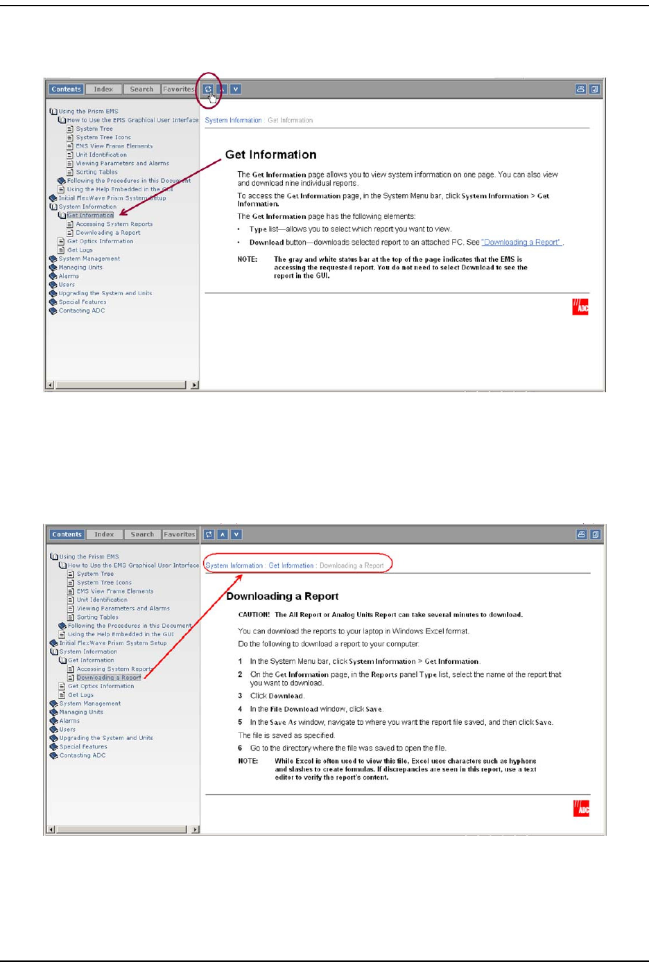
You can also use the Show in Contents but ton to show where a topic falls within the
book hierarchy:
Using the Orientation Links and Buttons
You can use the interact ive orient at ion links in the topic header. These links show
where t he topic falls within a chapt er. Click on the links in t he topic header to m ove
back one st ep in the book hierarchy.
Using t he Help Em bedded in the GUI
Page 52 FlexWave Pr ism Elem ent Managem ent System 7.1 User Manual
© 2011 ADC Telecommunications, Inc ADCP- 77-177 • I ssue 1 • July 2011
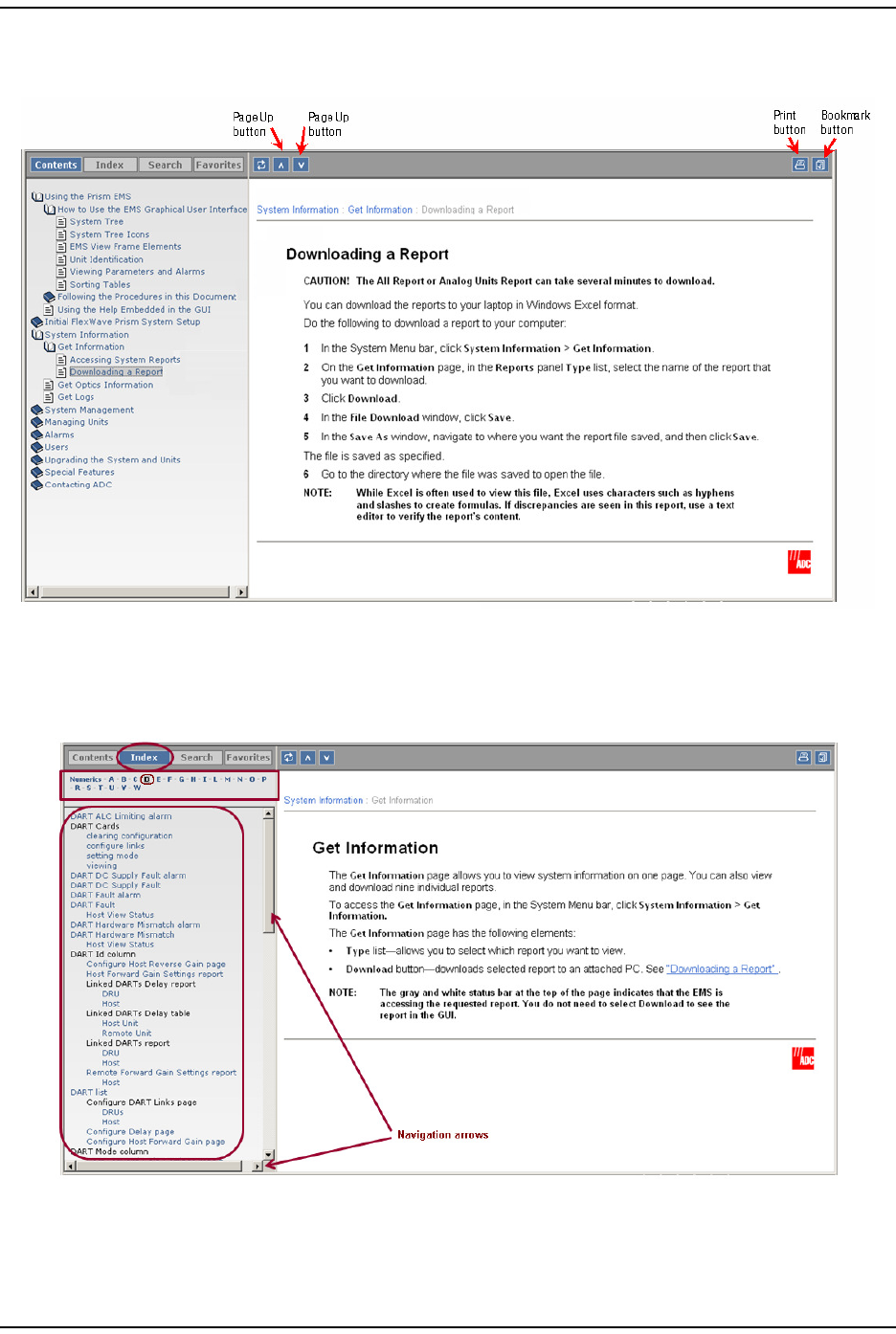
You can also use t he Page Up but t on, Page Down butt on, Print but t on, and
Bookm ark but t on t o bookm ark a t opic.
Using the Index Tab
Click Index t o open t he Index panel.
At the top of t he Index panel is t he alpha-num eric orient at ion tool. I n this exam ple,
the let ter D is selected, which results in only t hose indexed words t hat start with
Using t he Prism EMS
FlexWave Prism Elem ent Managem ent Syst em 7.1 User Manual Page 53
ADCP- 77- 1 77 • Issue 1 • July 2011 © 2011 ADC Telecom m unicat ions, I nc.
“ D” to display, in alphabetic order. Click on any of t he links t o go to the topic that
has t he indexed term in it .
To m ove up/ down or left / right t o change the orientation of the t ext in the I ndex
panel, use the navigation arrows.
Using the Search Tab
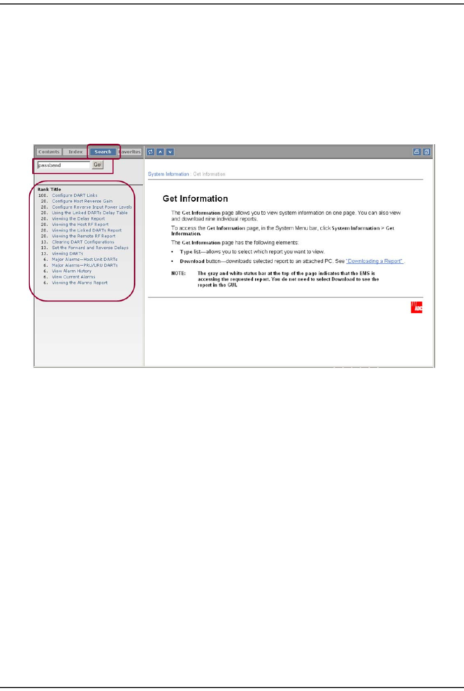
1Click Search t o open the Search panel.
2At the top of t he Search panel is a t ext box in which you ent er the term for which
you want t o search. I n t his exam ple the user is searching for t he word
“ passband.”
3To activate t he search, click the Go but ton.
The Search panel is populated wit h links t o t he t opics that contain the word
“ passband” and are ordered from top down in order of probabilit y of which t opic
will contain t he t opic for which you are searching.

Using t he Help Em bedded in the GUI
Page 54 FlexWave Pr ism Elem ent Managem ent System 7.1 User Manual
© 2011 ADC Telecommunications, Inc ADCP- 77-177 • I ssue 1 • July 2011
I nt entionally Blank Page

FlexWave Prism Elem ent Managem ent Syst em 7.1 User Manual Page 55
ADCP- 77- 1 77 • Issue 1 • July 2011 © 2011 ADC Telecommunications, Inc.
INITIAL FLEXWAVE PRISM SYSTEM SETUP
Minim um EMS Syst em Requirem ent s ........................................................................................ 56
Access the EMS .....................................................................................................................57
Set Session Tim eout ...............................................................................................................59
Set Dat e and Tim e ................................................................................................................. 60
Set Net work Connections ........................................................................................................63
Configure Basic Host Unit Propert ies ......................................................................................... 64
Label t he PRU/ URU................................................................................................................. 66
Label t he Host Opt ical Ports..................................................................................................... 67
Label PRU/ URU Optical Ports ...................................................................................................70
Configure DART Links .............................................................................................................71
Classic DART Models .........................................................................................................75
800 APAC iDEN Classic DART ........................................................................................ 75
800 SMR Classic DART................................................................................................. 75
900 SMR Classic .........................................................................................................76
2100 AWS Classic DART...............................................................................................76
Cellular Classic DART................................................................................................... 77
PCS Classic DART........................................................................................................77
SuperDART Models ........................................................................................................... 79
700 Lower ABC SuperDART ..........................................................................................79
700 UpperC SuperDART ............................................................................................... 79
2100 AWS SuperDART .................................................................................................79
EGSM 900 Super DART ................................................................................................. 79
GSM 1800 SuperDART .................................................................................................80
PCS SuperDART.......................................................................................................... 80
UMTS SuperDART .......................................................................................................80
DART Start and St op Frequencies .......................................................................................81
Set the Forward and Reverse Delays......................................................................................... 82
Using the Linked DARTs Delay Table ...................................................................................83
Filtering the Linked DARTs Delay Table ................................................................................ 84
Configure Host Forward Gain ...................................................................................................85
Configure Host Reverse Gain ................................................................................................... 88
Configure Rem ote For ward Gain ...............................................................................................91
Configure Reverse I nput Power Levels ......................................................................................94
The st eps provided in t his chapt er configure a basic Prism syst em that includes:
•one Host Unit ( Host )
•at least one Prism Rem ote Unit (PRU) .
Topics Page

Minim um EMS Syst em Requirem ent s
Page 56 FlexWave Pr ism Elem ent Managem ent System 7.1 User Manual
© 2011 ADC Telecommunications, Inc ADCP- 77-177 • I ssue 1 • July 2011
MINIMUM EMS SYSTEM REQUIREMENTS
The com puter t hat you use to remotely access t he EMS m ust m eet the following
m inim um requirem ent s:
•Windows 2000 or Windows XP operating system
•I nt ernet Explorer version 7.x or FireFox 3.6
•Net work I nt erface Card ( NI C)
•Et hernet cable with RJ- 45 connectors.
The EMS database can also be accessed rem otely using an SNMP m anager. I n this
case, the user interface varies depending on the SNMP m anager, but the
underlying param et ers, param et er values, and alarm s are the sam e as in the
st andard EMS int erface.
I nit ial FlexWave Prism System Setup
FlexWave Prism Elem ent Managem ent Syst em 7.1 User Manual Page 57
ADCP- 77- 1 77 • Issue 1 • July 2011 © 2011 ADC Telecom m unicat ions, I nc.
ACCESS THE EMS
NOTE: In the default configuration, the Craft port has a DHCP server that assigns an IP address
to the computer that is connected. You should therefore have your network interface
configured for DHCP, or configured with a static IP address in the same subnet, where the
default is 192.168.0.1/24.
1To allow t he EMS popup and alarm
screens t o funct ion correctly, do one
of the following:
•Disable the popup blocker for
your web browser.
•Enter t he syst em I P address in
the web browser’s t rust ed sites
list.
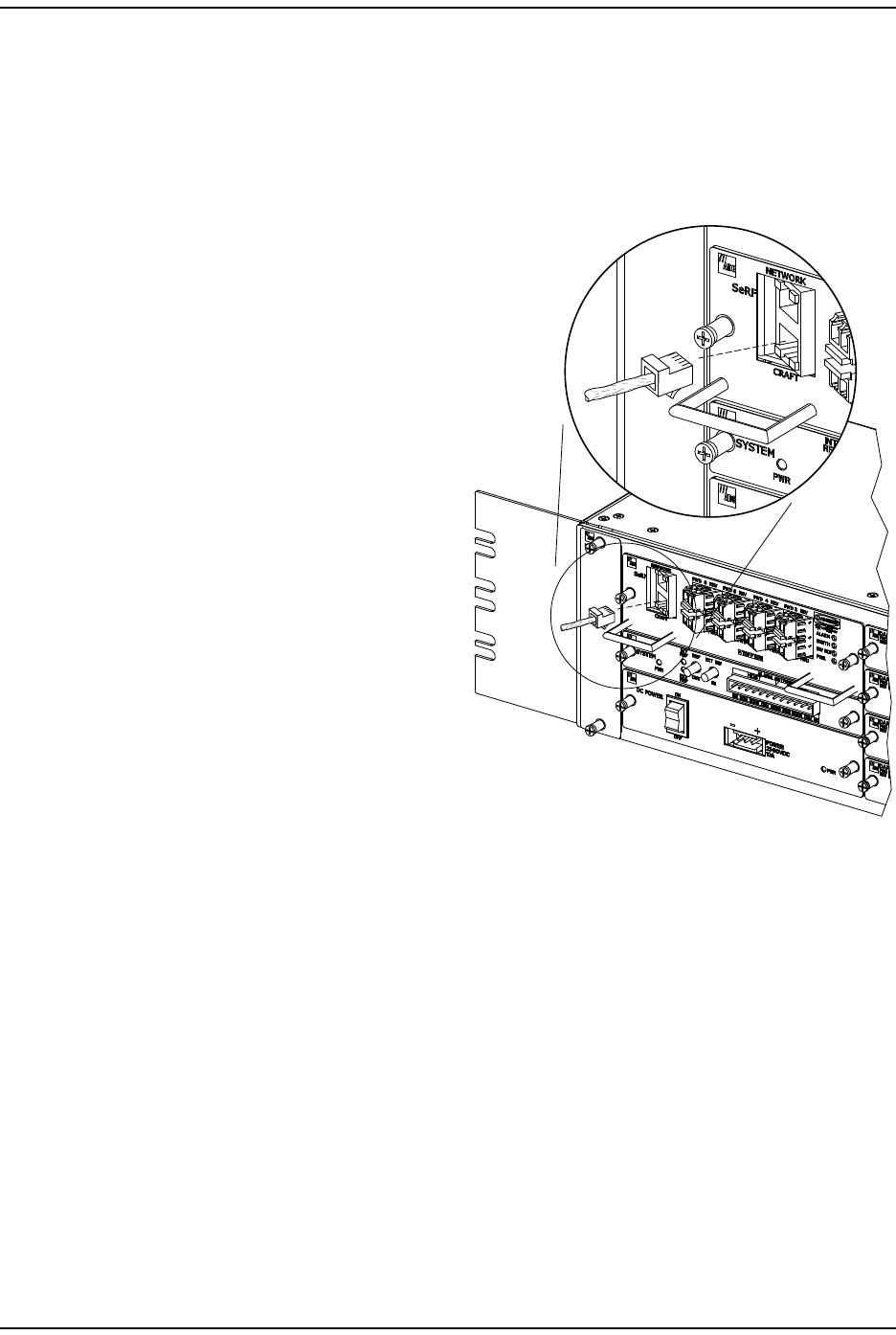
2Use an Et hernet CAT 5 cable
( st raight or crossover) with RJ-45
connect ors to connect a laptop to
the Craft port of the Host .
3Connect your com puter and st art a
web browser.
4I n t he web browser URL box, enter
the following I P address:
192.168.0.1
77073-075
RJ-45
Connector
Detail
Access the EMS
Page 58 FlexWave Pr ism Elem ent Managem ent System 7.1 User Manual
© 2011 ADC Telecommunications, Inc ADCP- 77-177 • I ssue 1 • July 2011
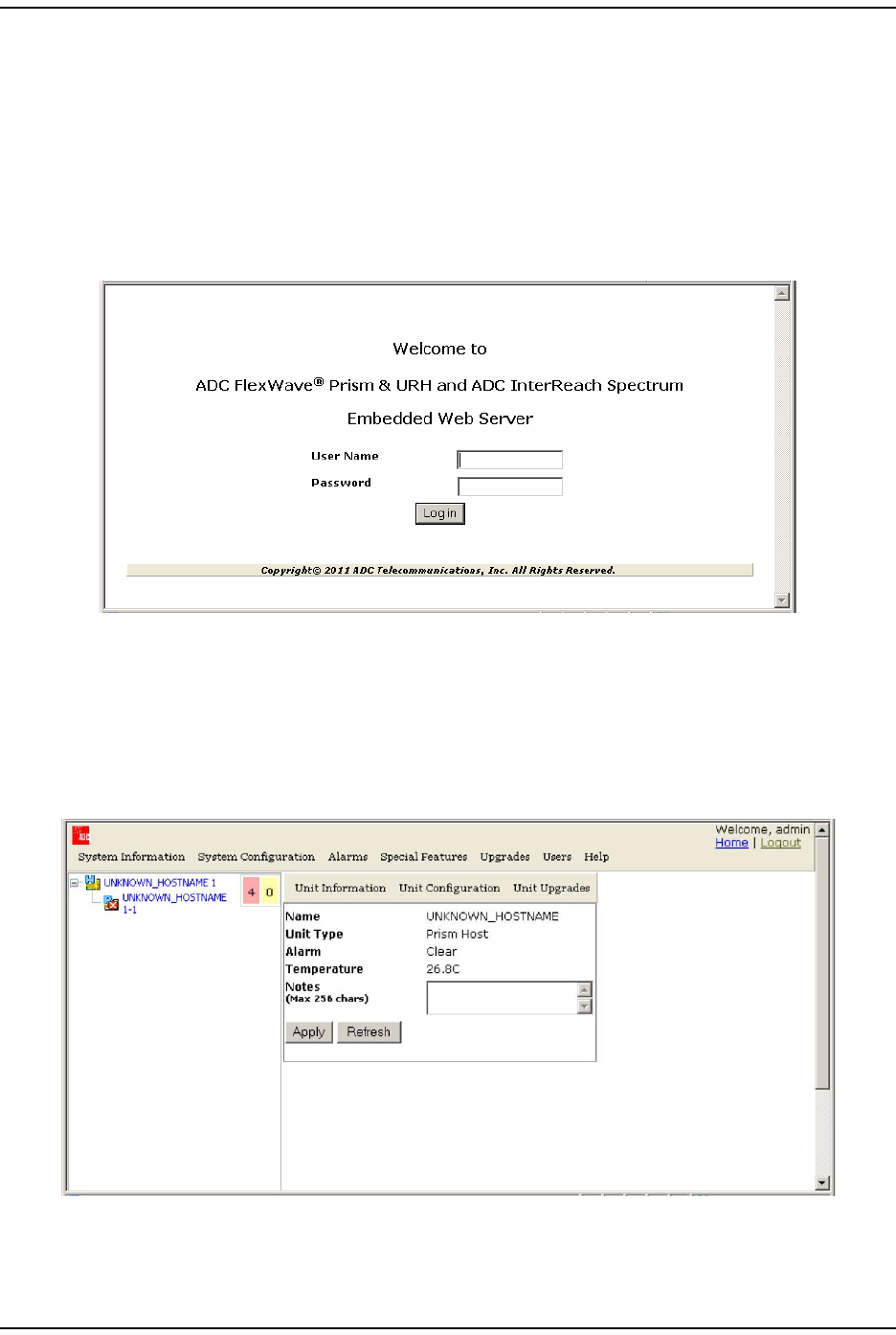
5When the Welcome to ADC FlexWave Prism & URH and ADC InterReach Spectrum window
opens:
aI n t he User Name box, t ype t he user nam e provided by ADC or by the Network
Adm inist rator. The default user nam e is admin.
bI n t he Password box, t ype the password provided by ADC or by t he Net work
Adm inist rator. The default password is adc123.
Once installation is com plet e, users can be added and passwords can be
changed. For further inform at ion, see “Users” on page 203.
6Click Log in to open the default page, which com prises the elem ents list ed
below.
•The Syst em Tree will be populated with inst alled devices, but no device will
be selected.
•I n t he EMS View Fram e, t he default page displays when the Host is selected
in the Syst em Tree.
I nit ial FlexWave Prism System Setup
FlexWave Prism Elem ent Managem ent Syst em 7.1 User Manual Page 59
ADCP- 77- 1 77 • Issue 1 • July 2011 © 2011 ADC Telecom m unicat ions, I nc.
SET SESSION TIMEOUT
NOTE: This feature is accessible only by a user logged in to the EMS as the admin user.
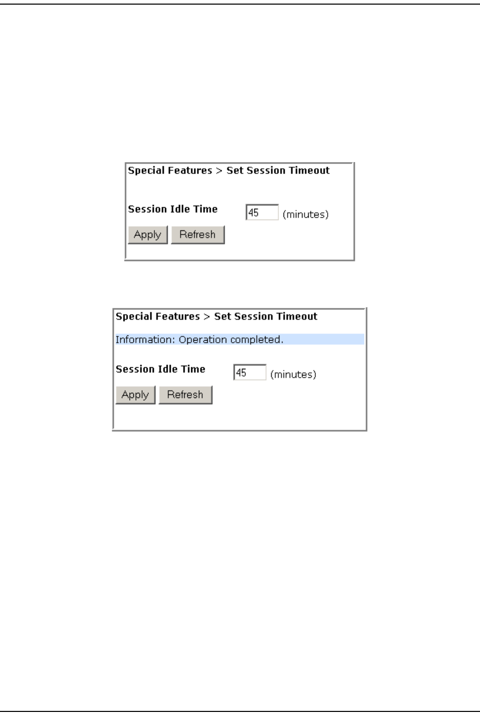
1To access the Set Session Timeout page, in t he Syst em Menu bar, click Special
Features > Set Session Timeout.
2I n t he Session Idle Time box, ent er in m inutes how long t he EMS session can be
idle before a forced log out occurs; t he value m ust be between 10 and 60
m inutes. The default is 30 m inut es.
3Click Apply. Once the syst em execut es the com m and, an Operation completed
m essage displays.

Set Date and Tim e
Page 60 FlexWave Pr ism Elem ent Managem ent System 7.1 User Manual
© 2011 ADC Telecommunications, Inc ADCP- 77-177 • I ssue 1 • July 2011
SET DATE AND TIME
The following rules apply t o the syst em tim e and date:
•The supported dat e and t im e range is from 1 January 2005 00: 00: 00
( 12 AM) to 31 Decem ber 2037 23: 59: 59 (11: 59: 59 PM) , where January is 1
and Decem ber is 12.
•Tim e zone and day light savings are not support ed.
•All PRUs synchronize t im e wit h the m anaging Host at t he t im e t he connected
PRU is discovered. The date and tim e on t he PRUs t hen synchronize to t he Host
and do not drift.
•I f t he syst em dat e or t im e is changed while a PRU is out of com m unicat ion wit h
the Host (for exam ple, loss of power or scheduled m aint enance) , once
com m unication is reest ablished it will take up to 10 m inutes for t he PRU to
display t he updated dat e or t im e.
•I f t he difference between the set tim e and t he present t im e is greater than the
session t im e out setting, t he user will be logged out. For example, if t he Session
Idle Time is set to 10 m inutes, and t he t im e set in t his procedure is 11: 10 AM
but it is act ually 11: 30 AM, t here is a 20 m inute difference, which t riggers t he
Session Idle Time and the user will be logged out.
NOTE: It can take up to 17 minutes before the updated time or date to take effect in connected
Remote Units.
NOTE: You can set the date and time at any time independent from one another. For example, to
change the time for daylight savings, open the System Date and Time page, click on the
hour shown in the System Time box, increase or decrease the hour by one, and then click
Apply.
I nit ial FlexWave Prism System Setup
FlexWave Prism Elem ent Managem ent Syst em 7.1 User Manual Page 61
ADCP- 77- 1 77 • Issue 1 • July 2011 © 2011 ADC Telecom m unicat ions, I nc.
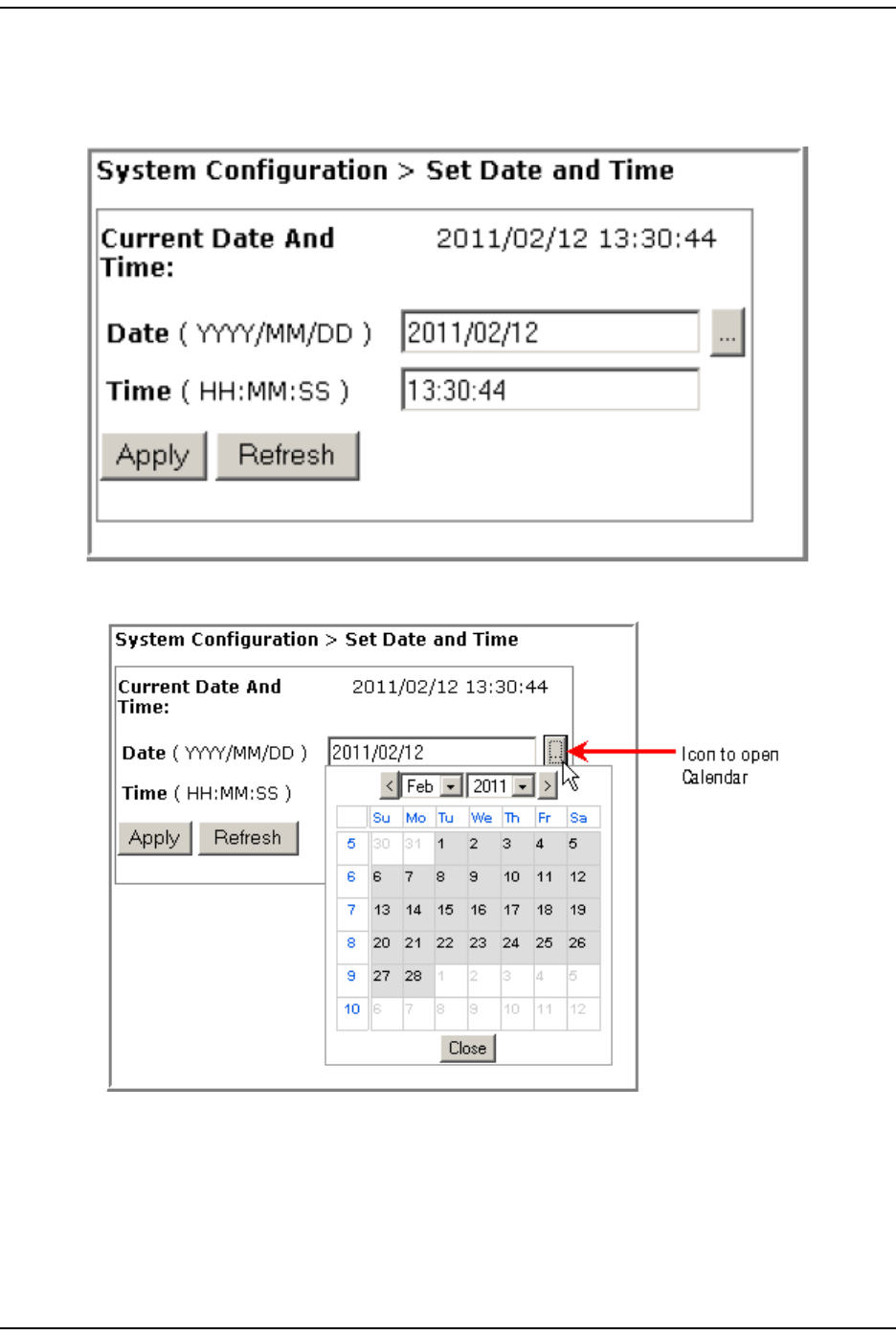
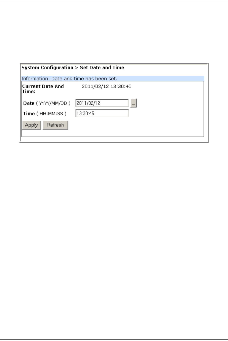
Do t he follow ing to se t t h e dat e and t im e:
1To access t he Set Date and Time page, in t he Syst em Menu bar, click System
Configuration > Set Date and Time.
2To change the date, click the … icon aft er the Date (YYYY/MM/DD) box.
3I n t he Calendar that opens, do t he following:
aI n the Month list, select the m onth.
bI f necessary, use the right arrow t o adjust t he year higher.
cI n the calendar, select t he dat e.
dClick Close.
Set Date and Tim e
Page 62 FlexWave Pr ism Elem ent Managem ent System 7.1 User Manual
© 2011 ADC Telecommunications, Inc ADCP- 77-177 • I ssue 1 • July 2011
4I n t he Time (HH:MM:SS) box, enter t he syst em tim e in the 24- hour clock
HH: MM: SS form at ( for exam ple, t o set the system t im e to 5: 19: 56 PM, you
would ent er 17:19:56) .
5I n t he Set Date and Time page, verify the date and tim e showing in t he System Date
and System Time fields.
6Click Apply. Once the syst em execut es t he com m and, an Operation completed
m essage displays.
I nit ial FlexWave Prism System Setup
FlexWave Prism Elem ent Managem ent Syst em 7.1 User Manual Page 63
ADCP- 77- 1 77 • Issue 1 • July 2011 © 2011 ADC Telecom m unicat ions, I nc.
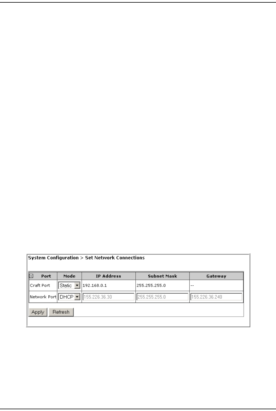
SET NETWORK CONNECTIONS
1To access t he Set Network Connections page, in the Syst em Menu bar, click System
Configuration > Set Network Connections.
2Use t he Networking Mode list to specify t he m ode under which I P addresses are
assigned to the Host Craft and Net work ports. A single I P address defines t he
system . This I P address is assigned to the Host either st atically or by the DHCP
server on the NOC. No user set ting/ I P configurat ion is required for t he
PRUs—I P addresses for connect ed PRUs are aut o assigned.
•DHCP—this m ode indicat es that t he Host is a DHCP client and expects an I P
address to be assigned by an ext ernal DHCP server through a network
Et hernet connect or. The Host Craft port has a DHCP server t hat can be used
to com m unicate with the Host direct ly, and from which you can access the
EMS.
•Static—the default m ode for t he Craft Port, with a default I P address of
192.168.0.1. The Static Networking Mode allows you t o set an I P address for
the Host and connected Rem ote Units t hat do not change unless you
m anually change them .
3I f you change a port to Static Networking Mode, t he address fields are enabled.
Ot herwise you cannot change t he network addresses. I f you set a port t o Static
Networking Mode, then do t he following:
aI n t he IP Address box, ent er a new I P address for t he syst em , in t he form at
of xxx.xxx.xxx.xxx.
bI n t he Subnet Mask box, enter a new Subnet Mask address for t he syst em , in
the form at of xxx.xxx.xxx.xxx.
cI n t he Gateway box, ent er a new Gat eway address for t he syst em , in t he
form at of xxx.xxx.xxx.xxx.
4Click Apply. Once the syst em execut es the com m and, an Operation completed
m essage displays.
Configure Basic Host Unit Properties
Page 64 FlexWave Pr ism Elem ent Managem ent System 7.1 User Manual
© 2011 ADC Telecommunications, Inc ADCP- 77-177 • I ssue 1 • July 2011
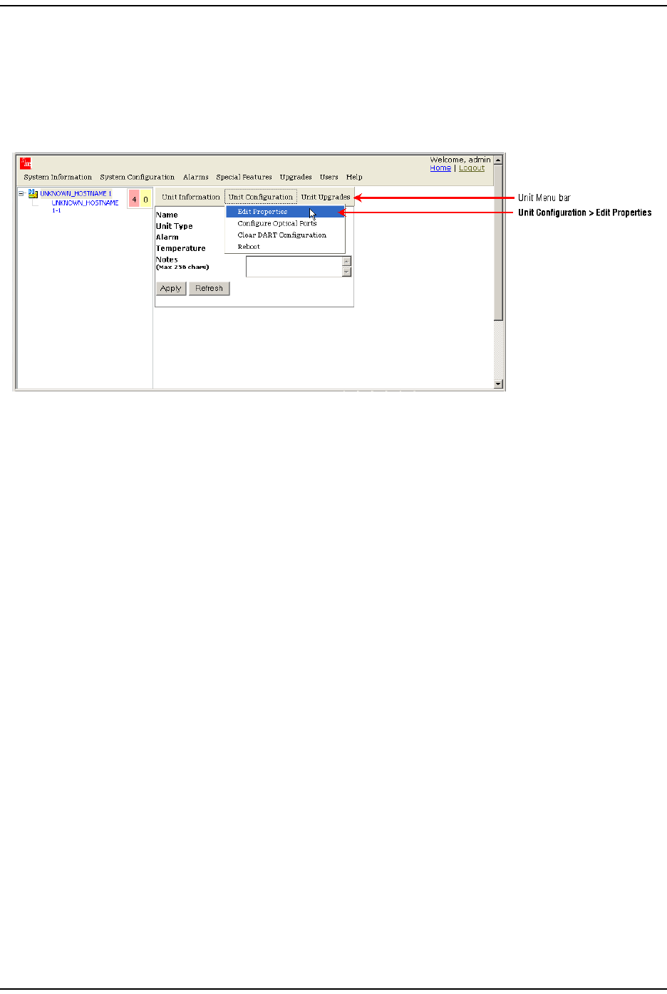
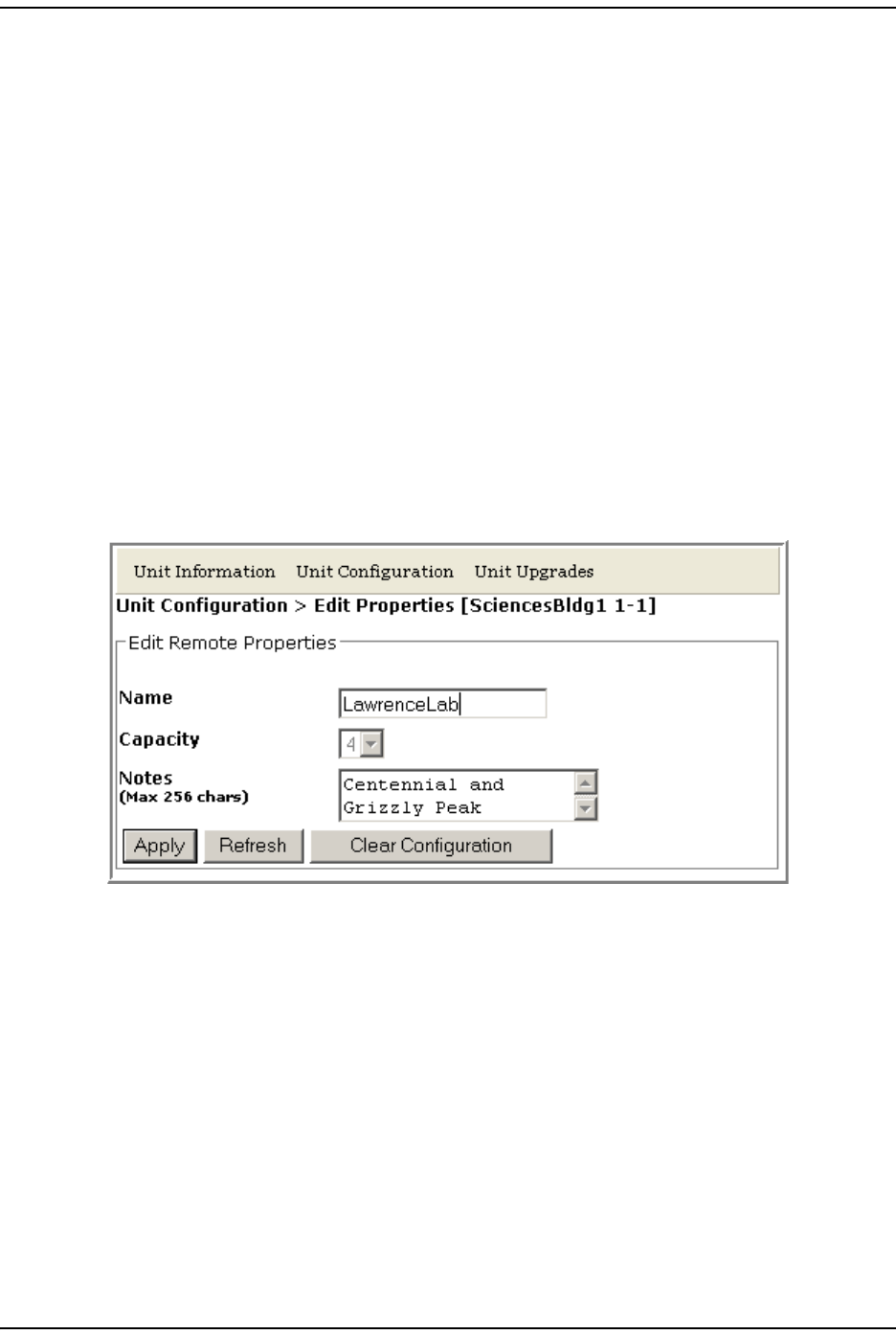
CONFIGURE BASIC HOST UNIT PROPERTIES
1I n t he Syst em Tree, click on t he Host icon.
2I n t he Unit Menu bar, click Unit Configuration > Edit Properties, to open the Unit
Configuration > Edit Properties page.
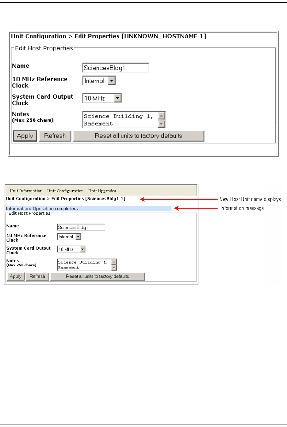
3I n t he Name box, enter an identifying nam e for t he Host . The Name m ust st art
wit h an alphabetical character, contain bet ween 5 and 40 charact ers
( alphanum eric or underscore only) , and contain no spaces.
4( Optional) The SeRF board on each Host and Rem ot e contains t he clock for t hat
unit. At t he Rem ote, t he reference is a clock derived from the Host clock. The
10 MHz Reference Clock default is Internal. You can change t he 10 MHz Reference Clock
sett ing to External, which allows you to frequency lock t he clock t o an external
10 MHz reference.
CAUTION! When using the 10 MHz external reference clock, the signal must be connected to the Host
before enabling the clock in the software. If an external 10MHz reference clock is selected
for operation, but is not present or outside of the frequency range of 10MHz +/- 5ppm,
communication between the Host and Remote over the optical fiber will fail.
5I n t he System Card Output Clock list, select one of the following:
•10 MHz t o set the Host as t he Syst em Card Out put Clock.
•Off to disable t he Syst em Card Out put Clock. Unless your syst em requires
the 10 MHz output , it is best t o leave t he System Card Output Clock disabled, as
this setting saves power and lowers em issions.
•30.72 MHz is not applicable t o a Prism syst em and should not be select ed.
I nit ial FlexWave Prism System Setup
FlexWave Prism Elem ent Managem ent Syst em 7.1 User Manual Page 65
ADCP- 77- 1 77 • Issue 1 • July 2011 © 2011 ADC Telecom m unicat ions, I nc.
6( Optional) Use t he Notes box t o ent er notes specific t o this Host . You can ent er
up to 256 charact ers; all keyboard charact ers can be used.
7Click Apply. Once the syst em execut es the com m and, an Operation completed
m essage displays.
Label the PRU/ URU
Page 66 FlexWave Pr ism Elem ent Managem ent System 7.1 User Manual
© 2011 ADC Telecommunications, Inc ADCP- 77-177 • I ssue 1 • July 2011
LABEL THE PRU/URU
1I n t he Syst em Tree, click the icon of t he PRU/ URU whose properties you want
to change.
2I n t he Unit Menu bar, click Unit Configuration > Edit Properties, to open the Unit
Configuration > Edit Properties page for t he selected PRU/ URU.
3I n t he Name box, enter an identifying nam e for t he PRU/ URU. The Name m ust
st art with an alphabet ical charact er, cont ain bet ween 5 and 40 charact ers
( alphanum eric or underscore only) , and contain no spaces.
4Leave t he Capacity set ting as is.
CAUTION! The Capacity setting pertains to the PRU/URU Remote SeRF Interface (RSI) board and the
number of RF groups available to the Remote Unit. This parameter is set during
manufacturing and should be changed only when the RSI board has been replaced. See
“Set the Capacity for a New Remote Unit RSI Board” on page 162.
5( Optional) Use t he Notes box t o ent er not es specific t o the select ed PRU/ URU.
You can enter up t o 256 charact ers; all keyboard charact ers can be used.
6Click Apply. Once the syst em execut es t he com m and, an Operation completed
m essage displays.
7Repeat t his process for each PRU/ URU in the syst em .
I nit ial FlexWave Prism System Setup
FlexWave Prism Elem ent Managem ent Syst em 7.1 User Manual Page 67
ADCP- 77- 1 77 • Issue 1 • July 2011 © 2011 ADC Telecom m unicat ions, I nc.
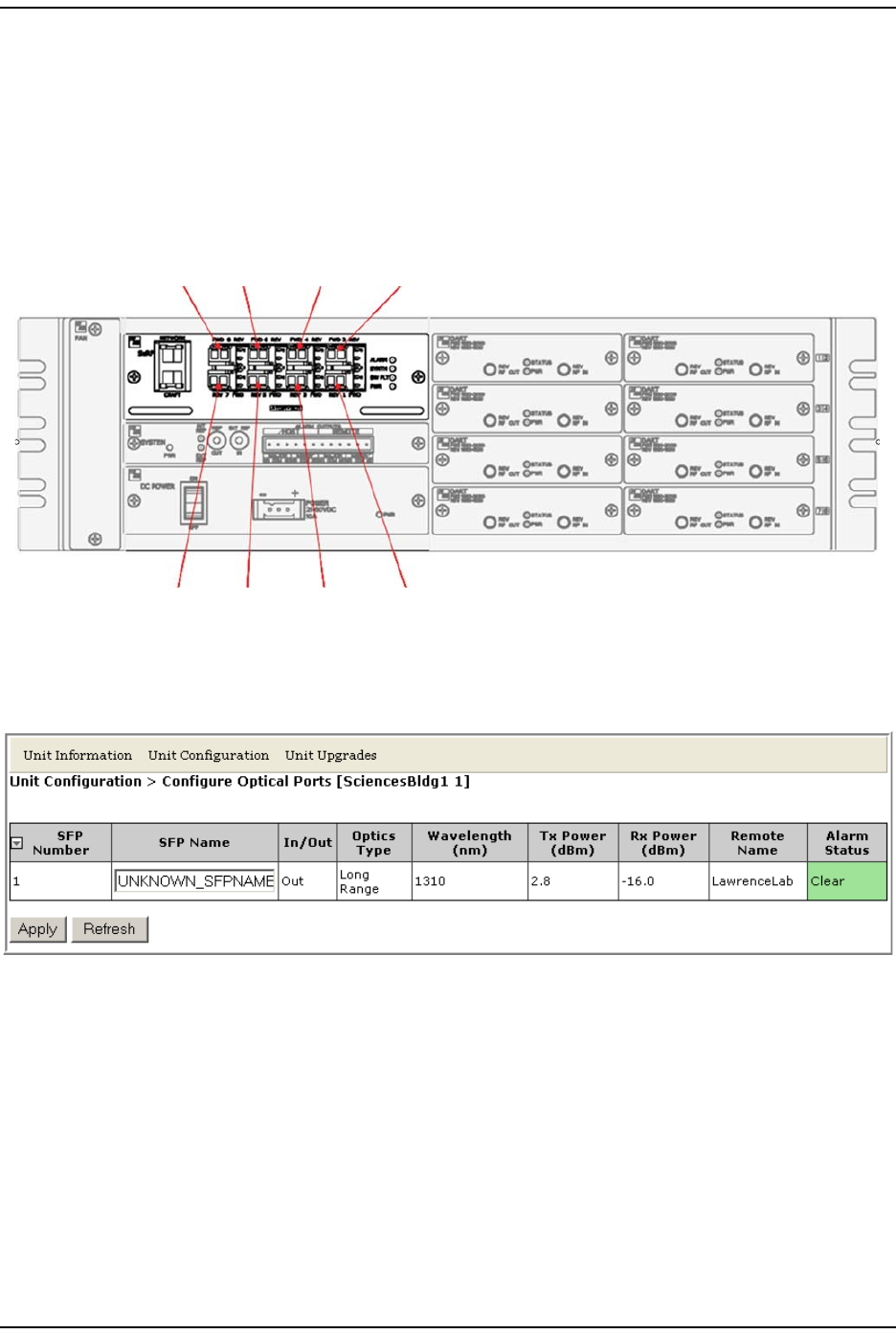
LABEL THE HOST OPTICAL PORTS
CAUTION! If fibers must be moved or reconfigured at any time during installation or setup, follow
the steps in “Moving or Reconfiguring Fibers” on page 122.
There can be up t o eight Host SeRF optical port s t hat correspond to the eight
physical port s on the Host . I n t his sect ion, you should label the Host SeRF Optical
port s t o provide for easier off-site m anagem ent.
1I n t he Syst em Tree, click on a Host icon.
2I n t he Unit Menu bar, click Unit Configuration > Configure Optical Ports, t o open the
Unit Configuration > Configure Optical Ports page.
86 4 2
75 3 1
77152-009

Label t he Host Opt ical Port s
Page 68 FlexWave Pr ism Elem ent Managem ent System 7.1 User Manual
© 2011 ADC Telecommunications, Inc ADCP- 77-177 • I ssue 1 • July 2011
3I n t he SFP Name box, ent er a label for t he select ed Optics port . The SFP Name
m ust st art with an alphabet ical character, contain 5 to 32 charact ers
( alphanum eric or underscore only) , and contain no spaces. The default SFP
Name is UNKNOWN_SFPNAME.
4Click Apply. Once the syst em execut es t he com m and, an Operation completed
m essage displays.
The Configure Optical Ports table provides t he following inform at ion.
•SFP Number—system assigned num ber (from 1 t o 8) for the Optical port s
•SFP Name—see St ep 3 on page 68.
•In/Out—used for cascading, which is not support ed in t his release. The Host will
therefore always be set as Out ( indicates t hat the forward link for t he connected
SFP is going away from t he Host ) and t he SFPs for all Rem ote Units will always
be set as In.
• Optics Type
–LongRange—26 dB
–IntermediateRange—18 dB)
•Wavelength (nm)—num ber displayed is t he wavelength t ransm itt ed through t his
port :
– Non-duplex and WDM configurations
1550 nm fwd
1310 nm rev
– CWDM configurations can be one of eight wavelengt hs:
1470 nm 1550 nm
1490 nm 1570 nm
1510 nm 1590 nm
1530 nm 1610 nm

I nit ial FlexWave Prism System Setup
FlexWave Prism Elem ent Managem ent Syst em 7.1 User Manual Page 69
ADCP- 77- 1 77 • Issue 1 • July 2011 © 2011 ADC Telecom m unicat ions, I nc.
•Tx Power (dBm)—launch power level in dBm of forward path signal.
– LongRange (LR)
m inim um is - 2 dBm
m axim um is 3 dBm .
– I nt erm ediat eRange (I R)
m inim um is - 5 dBm
m axim um is 0 dBm .
•Rx Power (dBm)—receive power level in dBm of reverse path signal, which
incorporat es the launch power of the Rem ot e Unit SFP plus all optical losses
( insertion losses, fiber cable loss, and so forth) .
– LongRange (LR)
m inim um is - 27 dBm
m axim um is - 9 dBm .
– I nt erm ediat eRange (I R)
m inim um is - 18 dBm
m axim um is 0 dBm .
•Remote Name or Host Name—when a Host Unit is select ed in t he Syst em Tree, t he
Configure Optical Ports table provides a colum n for Remote Name, which is nam e of
the Rem ot e Unit connect ed to this Optics por t . When a Rem ote Unit is selected
in the Syst em Tree, the Configure Optical Ports table provides a colum n for t he Host
Name, which is t he nam e of the Host connected to this Opt ics port .
•Alarm Status—whether an alarm is act ive. I f an alarm is act ive, there will be a
Minor or Major link that you click to open a dialog that defines t he active alarm ,
as described in “ Viewing Alarm Details” on page 45. The background color of
the Alarm Status cell also indicates t he alarm level ( see “Alarm Color Codes” on
page 44) .
Label PRU/ URU Opt ical Ports
Page 70 FlexWave Pr ism Elem ent Managem ent System 7.1 User Manual
© 2011 ADC Telecommunications, Inc ADCP- 77-177 • I ssue 1 • July 2011
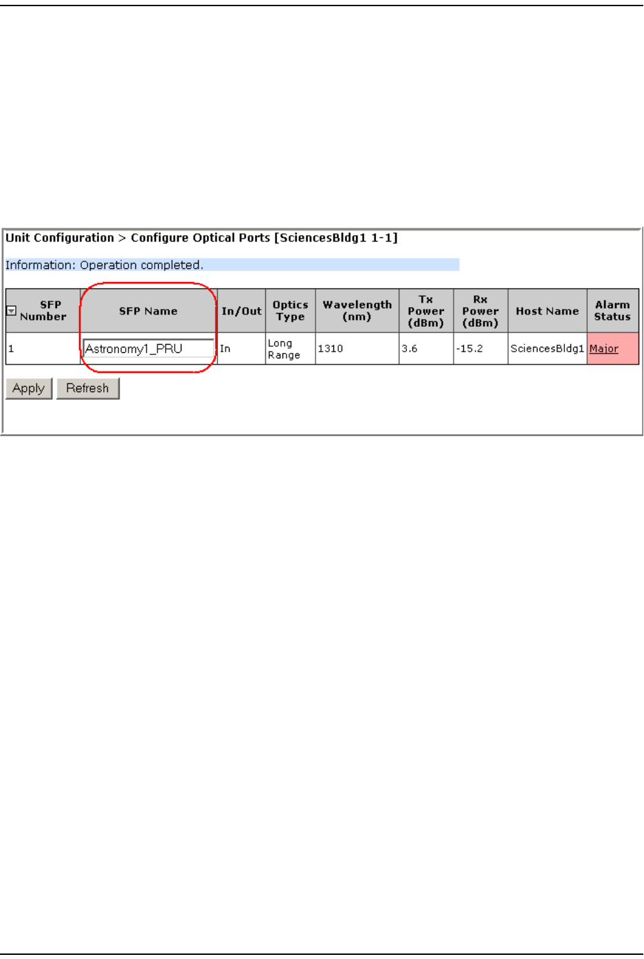
LABEL PRU/URU OPTICAL PORTS
1I n t he Syst em Tree, click on a PRU/ URU icon.
2I n t he Unit Menu bar, click Unit Configuration > Configure Optical Ports, t o open the
Unit Configuration > Configure Optical Ports page.
3I n t he SFP Name box, ent er a label for t he select ed Optics port . The SFP Name
m ust start with an alphabet ical character, cont ain between 5 and 32 characters
( alphanum eric or underscore only) , and contain no spaces. The default SFP
Name is UNKNOWN_SFPNAME.
4Click Apply. Once the syst em execut es t he com m and, an Operation completed
m essage displays.
5Repeat t his process for each PRU/ URU in the syst em .
The Configure Optical Ports t able provides the sam e inform ation as what is shown for
a Host Unit—see “ Label the Host Opt ical Port s” on page 67.
I nit ial FlexWave Prism System Setup
FlexWave Prism Elem ent Managem ent Syst em 7.1 User Manual Page 71
ADCP- 77- 1 77 • Issue 1 • July 2011 © 2011 ADC Telecom m unicat ions, I nc.
CONFIGURE DART LINKS
“ Linking” est ablishes an associat ion in soft ware between a part icular Host DART
and a particular Rem ote DART, enabling the t wo DARTs to act as an operational
unit in providing one RF band. There are four pre- requisites to this procedure:
•The Host DART and Rem ot e DART m ust be connected through the opt ical fiber
and be com m unicating with each other.
•To link t he Rem ot e Unit DARTs t o t he DARTs in a Host Unit, t he DARTs m ust
be t he sam e type e ( such as, Cellular t o Cellular).
•SuperDARTs and Classic DARTS do not operat e wit h each other. Link a
SuperDART t o a SuperDART and a Classic DART to a Classic DART.
•There m ust be a sufficient num ber of fiber tim eslot s available in order to
accom m odat e the request ed passband (for exam ple, PCS A band requires 3
t im eslot s) .
I n t he Configure DART Links page, all Rem ote DARTs are list ed that have t he sam e
band as t he selected Host DART. A link is established by selecting a Rem ote DART
to be paired with t he Host DART, and then clicking the Linked box. To provide for
an RF Sim u lcast , a Single Host DART can be linked t o up t o eight Rem ote DARTs.
Do the following to establish DART links:
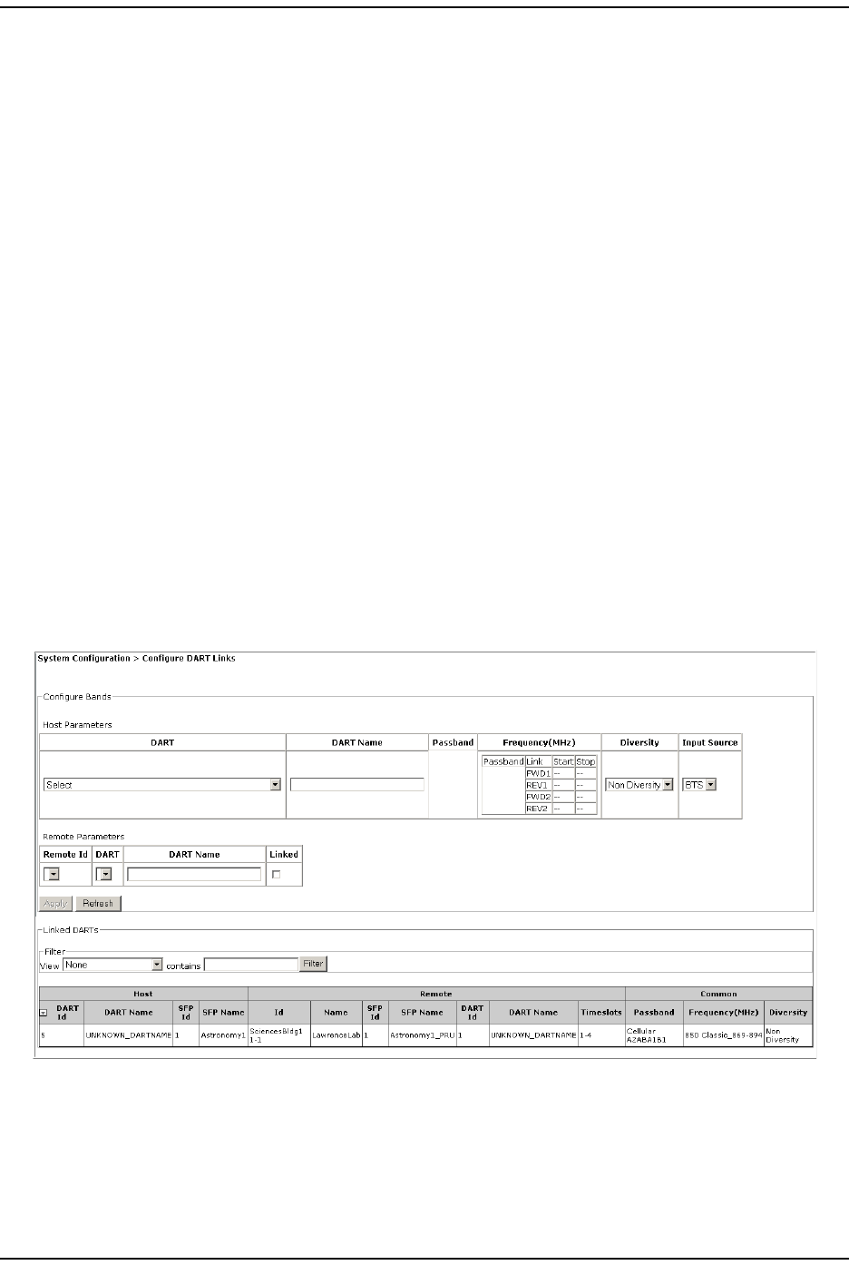
1To access t he Configure DART Links page, in t he Syst em Menu bar, click System
Configuration > Configure DART Links.
NOTE: For information on the Linked DARTs table at the bottom of the Configure DART Links
page, see “Viewing the Linked DARTs Report” on page 105.
You use the Configure Bands panel to configure the Host for DART linking, and the
Remote Parameters panel to configure the Rem ote Unit .
Configure DART Links
Page 72 FlexWave Pr ism Elem ent Managem ent System 7.1 User Manual
© 2011 ADC Telecommunications, Inc ADCP- 77-177 • I ssue 1 • July 2011
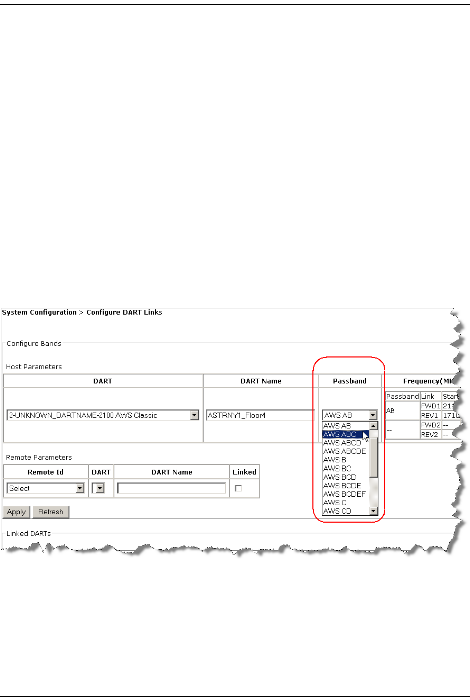
2I n t he Host Parameters panel, set the following param eters:
aI n t he DART list, select t he Host DART that you want to link t o the Rem ot e
Unit DART.
bI n t he DART Name box, enter a nam e for the DART, which m ust st art with an
alphabet ical charact er, contain bet ween 5 and 32 charact ers ( alphanum eric
or underscore only) , and contain no spaces.
cUse t he Passband colum n to set t he passband for t he selected DART.
•I f you are configuring a Classic DART, then refer to the passband
selection table in t he corresponding sect ion:
“ 800 APAC iDEN Classic DART” on page 75
“ 800 SMR Classic DART” on page 75
“ 900 SMR Classic” on page 76
“ 2100 AWS Classic DART” on page 76
“ Cellular Classic DART” on page 77
“ PCS Classic DART” on page 77
The following figure shows t he passband selections for t he 2100 AWS
Classic DART, which are described in “ 2100 AWS Classic DART” on
page 76.
I nit ial FlexWave Prism System Setup
FlexWave Prism Elem ent Managem ent Syst em 7.1 User Manual Page 73
ADCP- 77- 1 77 • Issue 1 • July 2011 © 2011 ADC Telecom m unicat ions, I nc.
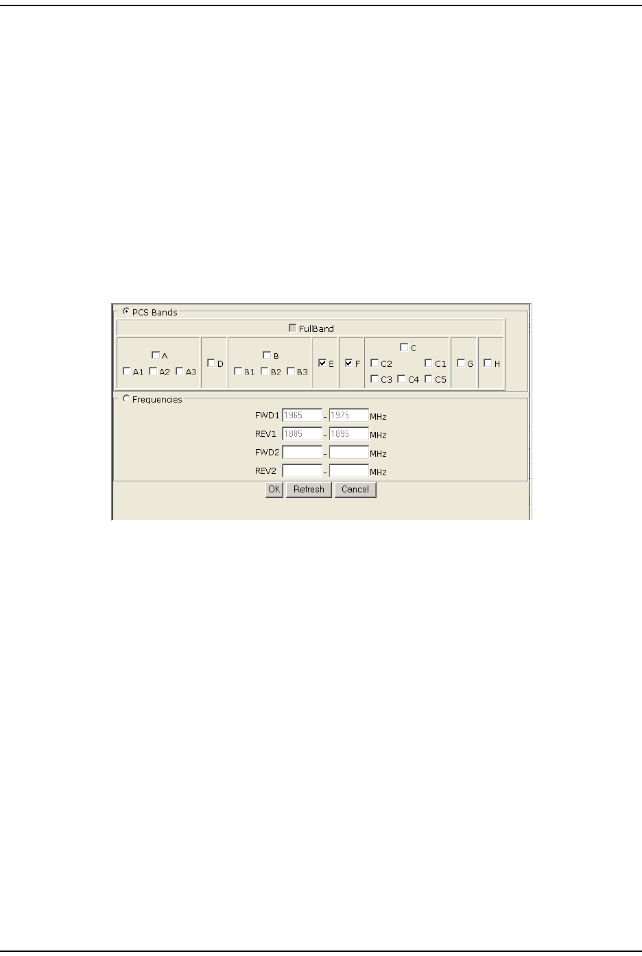
•I f you are configuring a SuperDART, in the Passband colum n, click on the
Configure link, and then in t he passband selection window t hat opens,
set the passband according to the rules specified for each SuperDART
type:
“ 700 Lower ABC SuperDART” on page 79
“ 700 UpperC SuperDART” on page 79
“ 2100 AWS SuperDART” on page 79
“ EGSM 900 SuperDART” on page 79
“ GSM 1800 SuperDART” on page 80
“ PCS SuperDART” on page 80
“ UMTS SuperDART” on page 80
The following figure shows t he passband select ions for a PCS SuperDART,
which are described in “ PCS SuperDART” on page 80.
The Frequency table provides a read-only t abular view of forward and reverse
pat hs.
•I n t he Diversity list , select whether t he DART is t o be configured as Diversity
or Non Diversity. For a diversity applicat ion, one DART will be configured
Non Diversity for t he prim ary FWD/ REV path signal and the ot her DART will
be configured Diversity. This selection t herefore det erm ines whether t he
DART Module being configured will carry the prim ary or secondary REV
( uplink) RF pat h.
•For dual DART configurations, such as dual- pcs, sm r800/ sm r900 and
dual-aws, both DARTs m ust have DART Diversity Status set to Non Diversity.
•I n t he Input Source list , select whether t he Wireless Operat or input will be
from t he BDA or BTS. Input Source det erm ines whet her System Test uses
external RF (BTS) or internal RF ( BDA) t o t est t he forward path. However,
this release does not support int ernal t one generation. Consequent ly,
setting the Input Source as either BDA or BTS assum es an external RF signal.
Default is BTS.
Configure DART Links
Page 74 FlexWave Pr ism Elem ent Managem ent System 7.1 User Manual
© 2011 ADC Telecommunications, Inc ADCP- 77-177 • I ssue 1 • July 2011
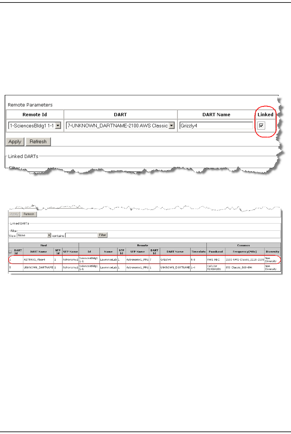
3I n t he Remote Parameters t able, set the following param eters:
aI n t he Remote Id list , select the Rem ote Unit whose DART you are linking to
the Host DART.
bI n t he DART list , select the Rem ot e Unit DART that you are linking.
cI n t he DART Name box, enter a nam e for the DART, which m ust st art with an
alphabet ical charact er, contain bet ween 5 and 32 charact ers ( alphanum eric
or underscore only) , and contain no spaces.
dSelect t he Linked box.
4Click Apply. The Linked DARTS t able at the bott om of the page updat es with the
new link.
5Repeat St ep through Step 4 for each Host and PRU/ URU DART pairing.
NOTE: Each link takes approximately 1 minute to establish.
I nit ial FlexWave Prism System Setup
FlexWave Prism Elem ent Managem ent Syst em 7.1 User Manual Page 75
ADCP- 77- 1 77 • Issue 1 • July 2011 © 2011 ADC Telecom m unicat ions, I nc.
Classic DART Models
The following sect ions describe the Prism Classic DART opt ions.
800 APAC iDEN Classic DART
Table 13 list s t he passband selections for 800 APAC iDEN Classic DARTs.
The 800 APAC iDEN DART also support s t he SMR Low and SMR Low Wide
passbands. The 800 APAC iDEN Classic DART can be linked t o a DART of the sam e
type and t o an 800 SMR Classic DART ( as long as t he passband is either SMR Low
or SMR Low Wide) . Table 14 specifies supported linking bet ween 800 SMR Classic
DARTs and 800 APAC iDEN Classic DARTs.
800 SMR Classic DART
Table 15 lists the passband select ions for 800 SMR Classic DARTs.
Table 13. 800 APAC iDEN Classic DART Passband Selection
Name Downlink Frequency
Range (MHz)
Uplink Frequency
Range (MHz)
800 APAC iDEN 851 - 870 806 - 825
Table 14. Linking 800 SMR Classic DARTs and 800 APAC iDEN Classic DARTs
Host DART PRU/URU DART Passbands
800APAC 800APAC low, wide,
apac
800APAC 800SMR low, wide
800SMR 800APAC low, wide
800SMR 800smr low, wide
Table 15. 800 SMR Classic DART Passband Selections
Name Downlink Frequency
Range (MHz)
Uplink Frequency
Range (MHz)
SMR Low 862 - 869 817 - 824
SMR Low Wide 851 - 869 806 - 824

Configure DART Links
Page 76 FlexWave Pr ism Elem ent Managem ent System 7.1 User Manual
© 2011 ADC Telecommunications, Inc ADCP- 77-177 • I ssue 1 • July 2011
900 SMR Classic
Table 16 list s t he passband select ions for 900 SMR Classic DARTs.
NOTE: When installed in a PRU, the 900 SMR Remote Classic DART supports only the SMR High
passband.
2100 AWS Classic DART
Table 17 list s t he passband select ions for 2100 AWS Classic DARTs.
Table 16. 900 SMR Classic DART Passband Selections
Name Downlink Frequency
Range (MHz)
Uplink Frequency
Range (MHz)
SMR High 935 - 940 896 - 901
SMR High/Paging 935 - 941 896 - 902
Table 17. 2100 AWS Classic DART Passband Selection
Name Downlink
Frequency
Range (MHz)
Uplink Frequency
Range (MHz)
A2110 - 2120 1710 - 1720
A+B 2110 - 2130 1710 - 1730
A+B+C 2110 - 2135 1710 - 1735
A+B+C+D 2110 - 2140 1710 - 1740
A+B+C+D+E 2110 - 2145 1710 - 1745
B2120 - 2130 1720 - 1730
B+C 2120 - 2135 1720 - 1735
B+C+D 2120 - 2140 1720 - 1740
B+C+D+E 2120 - 2145 1720 - 1745
B+C+D+E+F 2120 - 2155 1720 - 1755
C2130 - 2135 1730 - 1735
C+D 2130 - 2140 1730 - 1740
C+D+E 2130 - 2145 1730 - 1745
C+D+E+F 2130 - 2155 1730 - 1755
D2135 - 2140 1735 - 1740
D+E 2135 - 2145 1735 - 1745
D+E+F 2135 - 2155 1735 - 1755
E2140 - 2145 1740 - 1745
E+F 2140 - 2155 1740 - 1755
F2145 - 2155 1745 - 1755
I nit ial FlexWave Prism System Setup
FlexWave Prism Elem ent Managem ent Syst em 7.1 User Manual Page 77
ADCP- 77- 1 77 • Issue 1 • July 2011 © 2011 ADC Telecom m unicat ions, I nc.
Cellular Classic DART
Table 18 lists the passband select ions for Cellular Classic DARTs.
NOTE: The Cellular Classic Remote DART supports the same passbands as the Cellular Classic
Host DART. However, the LNA or Duplexer installed in the Remote Unit can restrain which
passbands are supported.
PCS Classic DART
Table 19 lists the passband select ions for PCS Classic DARTs.
Table 18. Cellular Classic DART Passband Selections
Name Downlink Frequency
Range (MHz)
Uplink Frequency
Range (MHz)
A'' + A 869 - 880 824 - 835
A870 - 880 825 - 835
A'' + A + A’ 869 - 891.5 824 - 846.5
A’ 890 - 891.5 845 - 846.5
B880 - 890 835 - 845
B’ 891.5 - 894 846.5 - 849
B + B’ 880 - 894 835 - 849
A'' + A + B + A' + B’ 869 - 894 824 - 849
A + B 870 - 890 825 - 845
Table 19. PCS Classic DART Passband Selections
Passband Downlink Frequency
Range (MHz)
Uplink Frequency
Range (MHz)
Passband Downlink Frequency
Range (MHz)
Uplink Frequency
Range (MHz)
A1 1930 - 1935 1850 - 1855 E+F+C2 1965 - 1982.5 1885 - 1902.5
A2 1935 - 1940 1855 - 1860 C1+G + H 1982.5 - 2000 1902.5 - 1920
A3 1940 - 1945 1860 - 1865 A+D 1930 - 1950 1850 - 1870
B1 1950 - 1955 1870 - 1875 A2+A3+D+B1 1935 - 1955 1855 - 1875
B2 1955 - 1960 1875 - 1880 A3+D+B1+B2 1940 - 1960 1860 - 1880
B3 1960 - 1965 1880 - 1885 D+B 1945 - 1965 1865 - 1885
C3 1975 - 1980 1895 - 1900 B+E 1950 - 1970 1870 - 1890
C4 1980 - 1985 1900 - 1905 B2+B3+E+F 1955 - 1975 1875 - 1895
C5 1985 - 1990 1905 - 1910 B3+E+F+C3 1960 - 1980 1880 - 1900
D1945 - 1950 1865 - 1870 E+F+C3+C4 1965 - 1985 1885 - 1905
E1965 - 1970 1885 - 1890 F+C 1970 - 1990 1890 - 1910
F1970 - 1975 1890 - 1895 C+G 1975 - 1995 1895 - 1915
G1990 - 1995 1910 - 1915 C4+C5+G + H 1980 - 2000 1900 - 1920
H1995 - 2000 1915 - 1920 B3+E+F+C2 1960 - 1982.5 1880 - 1902.5
C2 1975 - 1982.5 1895 - 1902.5 A+D+B1 1930 - 1955 1850 - 1875
C1 1982.5 - 1990 1902.5 - 1910 A2+A3+D+B1+B2 1935 - 1960 1855 - 1880

Configure DART Links
Page 78 FlexWave Pr ism Elem ent Managem ent System 7.1 User Manual
© 2011 ADC Telecommunications, Inc ADCP- 77-177 • I ssue 1 • July 2011
A1+A2 1930 - 1940 1850 - 1860 A3+D+B 1940 - 1965 1860 - 1885
A2+A3 1935 - 1945 1855 - 1865 D+B+E 1945 - 1970 1865 - 1890
A3+D 1940 - 1950 1860 - 1870 B+E+F 1950 - 1975 1870 - 1895
D+B1 1945 - 1955 1865 - 1875 B2+B3+E+F+C3 1955 - 1980 1875 - 1900
B1+B2 1950 - 1960 1870 - 1880 B3+E+F+C3+C4 1960 - 1985 1880 - 1905
B2+B3 1955 - 1965 1875 - 1885 E+F+C 1965 - 1990 1885 - 1910
B3+E 1960 - 1970 1880 - 1890 F+C+G 1970 - 1995 1890 - 1915
E+F 1965 - 1975 1885 - 1895 C+G + H 1975 - 2000 1895 - 1920
F+C3 1970 - 1980 1890 - 1900 B2+B3+E+F+C2 1955 - 1982.5 1875 - 1902.5
C3+C4 1975 - 1985 1895 - 1905 A+D+B1+B2 1930 - 1960 1850 - 1880
C4+C5 1980 - 1990 1900 - 1910 A2+A3+D+B 1935 - 1965 1855 - 1885
C5+G 1985 - 1995 1905 - 1915 A3+D+B+E 1940 - 1970 1860 - 1890
G + H 1990 - 2000 1910 - 1920 D+B+E+F 1945 - 1975 1865 - 1895
F+C2 1970 - 1982.5 1890 - 1902.5 B+E+F+C3 1950 - 1980 1870 - 1900
C1+G 1982.5 - 1995 1902.5 - 1915 B2+B3+E+F+C3+C4 1955 - 1985 1875 - 1905
A1930 - 1945 1850 - 1865 B3+E+F+C 1960 - 1990 1880 - 1910
A2+A3+D 1935 - 1950 1855 - 1870 E+F+C+G 1965 - 1995 1885 - 1915
A3+D+B1 1940 - 1955 1860 - 1875 F+C+G + H 1970 - 2000 1890 - 1920
D+B1+B2 1945 - 1960 1865 - 1880 A+D+B 1930 - 1965 1850 - 1885
B1950 - 1965 1870 - 1885 A2+A3+D+B+E 1935 - 1970 1855 - 1890
B2+B3+E 1955 - 1970 1875 - 1890 A3+D+B+E+F 1940 - 1975 1860 - 1895
B3+E+F 1960 - 1975 1880 - 1895 D+B+E+F+C3 1945 - 1980 1865 - 1900
E+F+C3 1965 - 1980 1885 - 1900 B+E+F+C3+C4 1950 - 1985 1870 - 1905
F+C3+C4 1970 - 1985 1890 - 1905 B2+B3+E+F+C 1955 - 1990 1875 - 1910
C1975 - 1990 1895 - 1910 B3+E+F+C+G 1960 - 1995 1880 - 1915
C4+C5 +G 1980 - 1995 1900 - 1915 E+F+C+G + H 1965 - 2000 1885 - 1920
C5+G + H 1985 - 2000 1905 - 1920
Table 19. PCS Classic DART Passband Selections
Passband Downlink Frequency
Range (MHz)
Uplink Frequency
Range (MHz)
Passband Downlink Frequency
Range (MHz)
Uplink Frequency
Range (MHz)
I nit ial FlexWave Prism System Setup
FlexWave Prism Elem ent Managem ent Syst em 7.1 User Manual Page 79
ADCP- 77- 1 77 • Issue 1 • July 2011 © 2011 ADC Telecom m unicat ions, I nc.
SuperDART Models
The following sect ions describe the Prism SuperDART options.
700 Lower ABC SuperDART
The 700 Lower ABC SuperDART support s t he following subbands: A, B, C.
Table 20 lists t he passband select ions for 700 Lower ABC SuperDARTs.
700 UpperC SuperDART
The 700 UpperC SuperDART support s t he following passband: Upper C.
Table 21 list s t he passband selections for 700 ABC SuperDARTs.
2100 AWS SuperDART
You can select any num ber of t he subbands based on the lim it ations specified
below.
•The 2100 AWS SuperDART support s t he following passbands: A, B, C, D, E, F.
•You can select up to two non-contiguous set s of subbands, but there m ust be
at least a 5 MHz gap between the bands.
•The St art and St op frequencies are in t he range of 2110MHz - 2155MHz.
EGSM 900 SuperDART
The EGSM 900 SuperDART support s t he selection of a St art and St op frequency
for t he passband in the range of 925MHz - 960MHz.
Table 20. 700 Lower ABC SuperDART Passband Selection
Name Downlink Frequency
Range (MHz)
Uplink Frequency
Range (MHz)
A728 - 734 698 - 704
B734 - 740 704 - 710
C740 - 746 710 - 716
Table 21. 700 UpperC SuperDART Passband Selection
Name Downlink Frequency
Range (MHz)
Uplink Frequency
Range (MHz)
UpperC 746 - 756 776 - 786

Configure DART Links
Page 80 FlexWave Pr ism Elem ent Managem ent System 7.1 User Manual
© 2011 ADC Telecommunications, Inc ADCP- 77-177 • I ssue 1 • July 2011
GSM 1800 SuperDART
You can select a St art and St op frequency for t he passband in the frequency range
of 1805 MHz - 1880 Mhz.
PCS SuperDART
PCS SuperDARTs support t he following subbands: A, B, C, D, E, F, G, H, A1, A2,
A3, B1, B2, B3, C1, C2, C3, C4, C5.
You can select any num ber of t he subbands based on the lim it ations specified
below:
•The subband A cannot be chosen in conjunct ion wit h A1, A2, or A3.
•The subband B cannot be chosen in conj unct ion with B1, B2, or B3.
•The subband C cannot be chosen in conj unct ion wit h C1, C2, C3, C4, or C5.
•The subbands C1 and C2 cannot be chosen in conj unct ion with t he subbands
C, C3, C4, or C5.
•The subbands C3, C4, and C5 cannot be chosen in conj unct ion wit h the
subbands C, C1, or C2.
•Up t o two non- contiguous set s of subbands can be select ed, and t here m ust be
m ore than a 5 MHz gap bet ween the bands.
The PCS SuperDART supports t he following St art and Stop frequencies:
•The PCS RF SuperDART support s t he selection of a Start and Stop frequency
for t he passband as listed in Table 19.
•The PCS RF SuperDART St art and Stop frequencies are in t he range of
1930MHz - 2000MHz.
UMTS SuperDART
You can select a St art and St op frequency for t he passband in the frequency range
of 2110 MHz - 2170 MHz.

I nit ial FlexWave Prism System Setup
FlexWave Prism Elem ent Managem ent Syst em 7.1 User Manual Page 81
ADCP- 77- 1 77 • Issue 1 • July 2011 © 2011 ADC Telecom m unicat ions, I nc.
DART Start and Stop Frequencies
Host SuperDARTs support the select ion of a St art and St op frequency for t he
passband or for t he selection of subbands ( up to two st art -st op frequency pairs
m ay be select ed as long as t he t wo pairs are at least 5 MHz apart and one is lim ited
to 39 MHz and the other is lim ited t o 25 MHz) .
NOTE: Start/Stop frequencies and subbands may not be used at the same time.
Table 22 list s t he supported st art- st op frequency ranges for SuperDARTs.
Table 22. Supported SuperDART Stop/Start Frequency Ranges
Frequency
Range
(MHz)
Timeslots
6 1
12 2
18 3
25 4
39 6
45 8
75 12

Set t he Forward and Reverse Delays
Page 82 FlexWave Pr ism Elem ent Managem ent System 7.1 User Manual
© 2011 ADC Telecommunications, Inc ADCP- 77-177 • I ssue 1 • July 2011
SET THE FORWARD AND REVERSE DELAYS
NOTE: The system comes up with a default delay. Once linking is complete, the system will
calculate the actual delay. The initial parameters that are set may therefore be out of
range. If necessary, correct the delay within the available range.
NOTE: If part of a simulcast, ensure that all links in the simulcast are set to the same delay
value.
NOTE: For information on the Linked DARTs Delay table at the bottom of the page, see “Using
the Linked DARTs Delay Table” on page 83.
1To access t he Configure Delay page, in the Syst em Menu bar, click System
Configuration > Configure Delay.
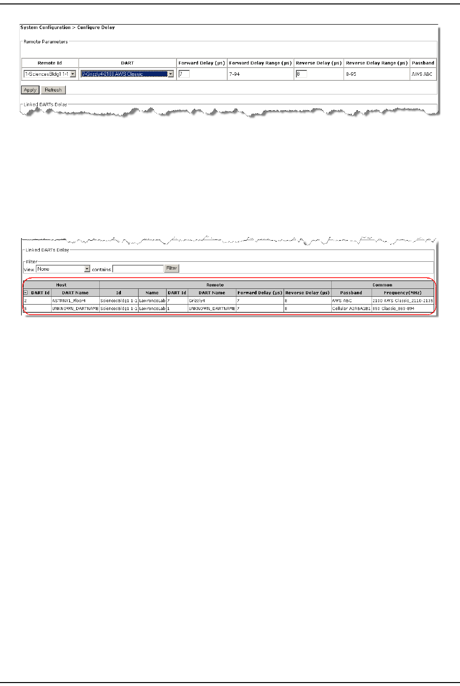
2I n t he Remote Parameters t able, do the following:
aI n t he Remote Id list, select t he Rem ote Unit for which you want to configure
the delay settings.
bI n t he DART list, select t he DART for which you want to configure t he delay
settings. Only t hose DARTS t hat have been linked will be available in t he
DART list . The following inform ation is populated in the Remote Parameters
table, which corresponds t o the Rem ot e Unit and DART that you have
select ed.
•Forward Delay (s) —t he Forward Range in m icroseconds available for the
select ed DART
•Forward Delay Range (s) —the Forward Delay Range in m icroseconds for
the select ed DART
•Reverse Delay (s) —the Reverse Delay in m icroseconds available for t he
select ed DART
•Reverse Delay Range (s) —the Reverse Delay Range in m icroseconds for
the select ed DART
•Passband—t ype of passband provided by t he DART
cI f necessary, change the Forward Delay and the Reverse Delay:
•Forward Delay (s) box—enter t he act ual delay in m icroseconds t hat will
be applied to the RF forward pat h signal. The Forward Delay Range ( s) field
displays valid set tings for t he Forward Delay.
•Reverse Delay (s) box—enter the actual delay in m icroseconds t hat will
be applied to t he RF reverse path signal. The Reverse Delay Range ( s) field
displays valid set tings for t he Reverse Delay.
I nit ial FlexWave Prism System Setup
FlexWave Prism Elem ent Managem ent Syst em 7.1 User Manual Page 83
ADCP- 77- 1 77 • Issue 1 • July 2011 © 2011 ADC Telecom m unicat ions, I nc.
3Click Apply. The Operation complete m essage displays, and the Remote Parameters
table clears so you can set the delay for anot her DART.
4Repeat St ep 2 t hrough St ep 3 for each DART.
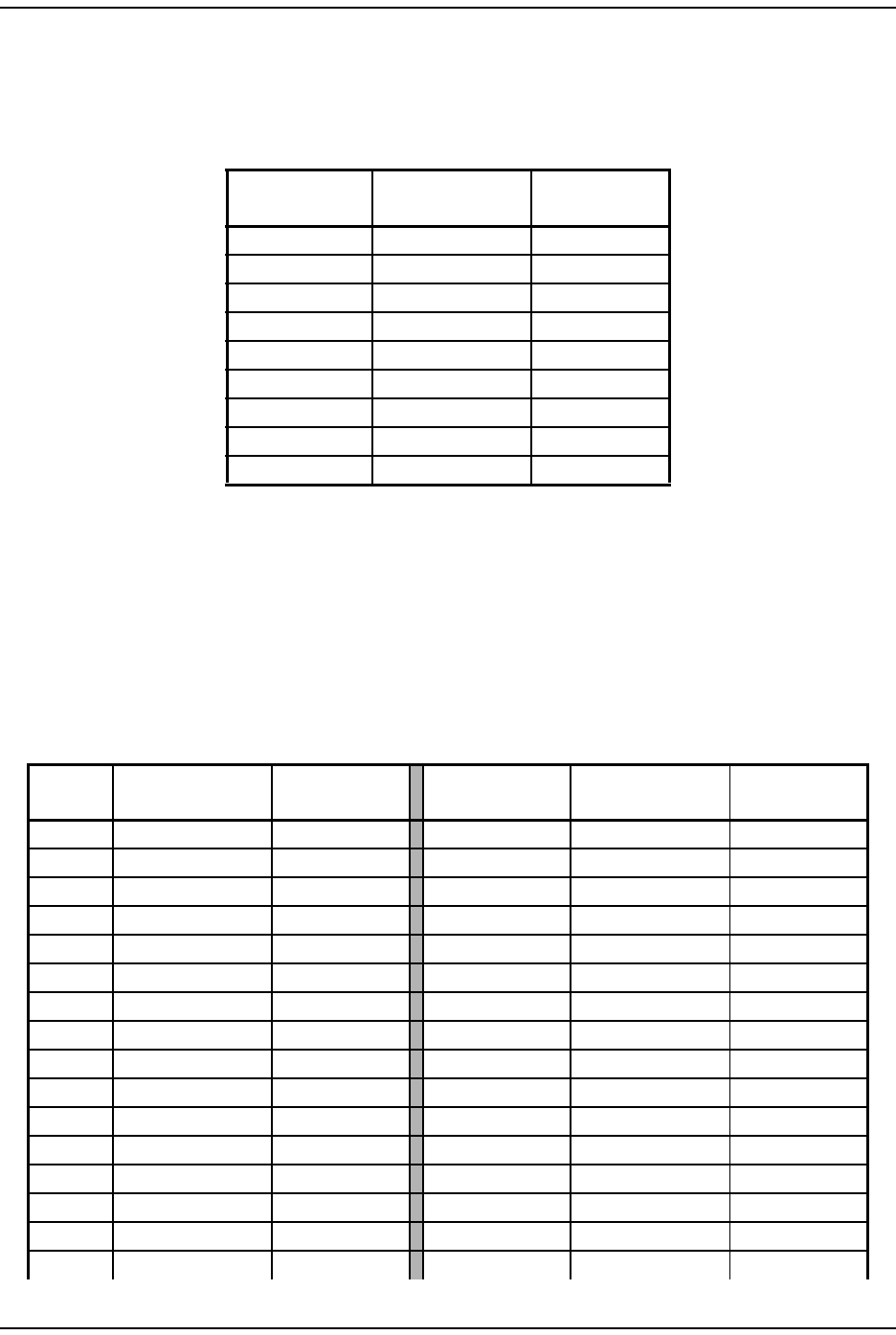
Using the Linked DARTs Delay Table
The Linked DARTs Delay table provides t he following inform ation:
•Host colum ns—identifies t he Host in the link
–DART Id—num ber of t he Host slot in which t he DART is inst alled
–DART Name—user- defined nam e for t he Host DART
•Remote colum ns—identifies t he Rem ot e and it s elem ents
–Id—Unit I D of PRU/ URU based upon layered address; see “ Unit
I dent ification” on page 43
–Name—user- defined label for t he PRU/ URU
–DART Id—PRU/ URU slot num ber in which t he DART is inst alled
–DART Name—user- defined nam e for t he Rem ot e DART
–Forward Delay ( s) —user request ed FWD RF pat h delay in m icroseconds
–Reverse Delay ( s) —user requested REV RF path delay in m icroseconds
•Common colum ns—configuration settings com m on t o t he Host and Rem ote( s)
–Passband—t ype of passband provided by t he DART.
–Frequency (MHz)—passband frequency of t he DART
Set t he Forward and Reverse Delays
Page 84 FlexWave Pr ism Elem ent Managem ent System 7.1 User Manual
© 2011 ADC Telecommunications, Inc ADCP- 77-177 • I ssue 1 • July 2011
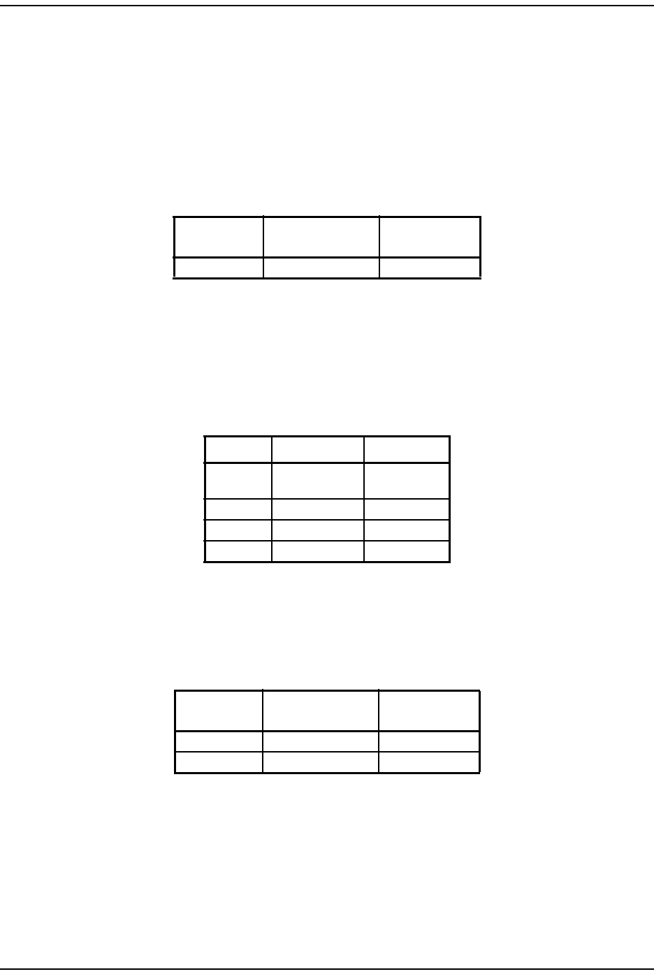
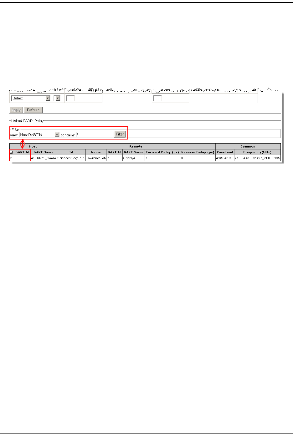
Filtering the Linked DARTs Delay Table
1I n t he Filter panel View list , select a filter t o be applied to t he t able.
2In the contains box, ent er filter criteria.
3Click Filter to apply t he filt er.
I n t he following exam ple, t he Linked DARTs Delay t able has been filtered t o show
only t hose Host Units with a DART Id t hat contains “ 2” .

I nit ial FlexWave Prism System Setup
FlexWave Prism Elem ent Managem ent Syst em 7.1 User Manual Page 85
ADCP- 77- 1 77 • Issue 1 • July 2011 © 2011 ADC Telecom m unicat ions, I nc.
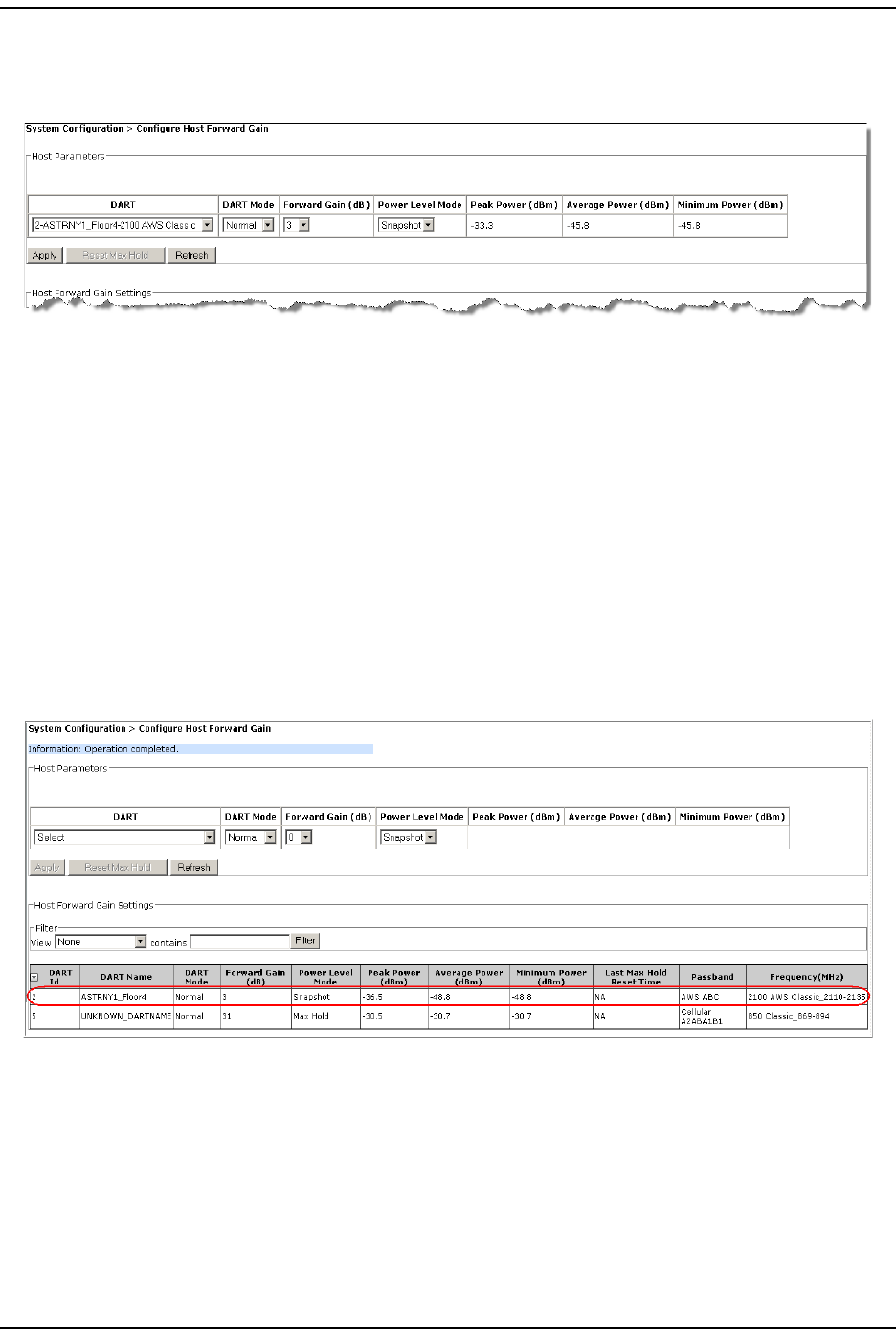
CONFIGURE HOST FORWARD GAIN
NOTE: Digital power measurements are inaccurate when ALC is active.
Follow these st eps t o set t he Forward Gain value for the Host DART.
1Determ ine what the Host DART Forward Gain should be. Use a signal generator
and spect r um analyzer t o m easure t he uplink attenuat ion from t he Host to the
BTS, and t he FWD power at the Host from the BTS to determ ine unloaded
power level.
The Host DART expects signal levels from -25 to +5 dBm. I f t he fully loaded signal
is + 5 dBm , t hen t he DART forward gain should be set to 0 dB, if the fully loaded
signal is - 25 dBm , then the DART Forward Gain should be set to 31 dB. The
equation is:
DART Forward Gain = 5 - fully Loaded Base St ation Signal
CAUTION! If you are setting up the system when no calls are going through, you must allow
headroom for a fully loaded forward path. For CDMA protocols, the difference from
unloaded to fully loaded is typically 8dB, so if the unloaded signal is -15dBm, then the
fully loaded input would be -7 dBm and the Host Forward Gain should be set to 5-(-7) = 12
dB.
The same rules applies for GSM carriers, except that the unloaded to loaded is
determined by the equation 10*log10(# RF Channels). So if there are 4 GSM RF Channels,
then the loaded forward path is 6 dB above unloaded.
If sufficient headroom is not present, then the LPA can be over-powered causing a Loss
Of Service.
CAUTION! When configured correctly, the Host DART Forward input can handle peaks of 14dB above
the BTS signal level. For example, if the fully loaded CDMA carrier is -25dBm, then peaks
up to -11 dBm can be handled (CDMA peak to average is typically 10-12 dB). If the peaks
exceed the 14 dB of headroom, then Automatic Level Control (ALC) will occur to prevent
over-driving the A/D Converter.
NOTE: In the EMS GUI, the reverse path gain range for Classic DARTs is 5 to 36 dB, which
indicates actual reverse path system gain. If you set this gain through the SNMP SET
commands, then the gain range is 0 to 31 dB, which maps to the actual GUI/system
reverse path gain range of 5 to 36 dB.

Configure Host Forward Gain
Page 86 FlexWave Pr ism Elem ent Managem ent System 7.1 User Manual
© 2011 ADC Telecommunications, Inc ADCP- 77-177 • I ssue 1 • July 2011
2I n t he EMS, do the following t o set the Host Forward Gain param et ers:
aTo access t he Configure Host Forward Gain page, in the Syst em Menu bar, click
System Configuration > Configure Host Forward Gain.
bI n t he Host Parameters table DART list , select t he Host DART that you want to
configure. Ot her inform at ion in the Host Parameters t able is updat ed to show
settings for t he selected DART.
cI n t he DART Mode list , select one of the following:
•Standby—forces the RF funct ion t o be m ut ed in the Host and its linked
Rem ote Unit.
•Normal—allows t he syst em t o operate norm ally (RF funct ion not forced t o
be m ut ed), assum ing all ot her syst em com ponents are in proper working
order. (Default set ting.)
dI n t he Fwd Gain (dB) list, select t he Forward Gain value of 0 t o 31 dB, based
upon the fully loaded forward pat h signal level from t he Base Station.
eI n t he Power Level Mode list , select one of the following:
•Snapshot—provides a “ snap-shot ” or current RF m easurem ent for t he
select ed Rem ot e Unit DART ( default set ting).
•Max Hold—ret ains t he m axim um values for peak and peak average, and
the m inim um values for m inim um average since the last Max Hold Reset.
NOTE: The Power Level Mode is disabled if the:
• DART Operating mode is set to Standby
• DART Pass Band (Timeslots) parameter is set to Undefined (default)
• DART Diversity Status is set to Diversity.
I nit ial FlexWave Prism System Setup
FlexWave Prism Elem ent Managem ent Syst em 7.1 User Manual Page 87
ADCP- 77- 1 77 • Issue 1 • July 2011 © 2011 ADC Telecom m unicat ions, I nc.
fI f you set the Power Level Mode to Max Hold, you can click Reset Max Hold to reset
the Max Hold values. The Host Forward Gain Settings t able updates with the new
set t ings.
The Host Parameters t able provides the following inform ation:
•Peak Power (dBm)—shows t he highest ( peak) power level reached by t he
Host DART
•Average Power (dBm)—shows the average power level reached by t he Host
DART
•Minimum Power (dBm)—shows the m inim um power level reached by the
Host DART
gClick Apply.
•Once t he syst em execut es t he com m and, an Operation completed m essage
displays.
•The Host Forward Gain Settings t able at the bott om of t he page is updated
wit h the new settings.
hRepeat St ep b on page 86 through St ep g for each Host DART.
For inform ation on the Host Forward Gain Settings table, see “ Viewing the Host RF
Report ” on page 108.

Configure Host Reverse Gain
Page 88 FlexWave Pr ism Elem ent Managem ent System 7.1 User Manual
© 2011 ADC Telecommunications, Inc ADCP- 77-177 • I ssue 1 • July 2011
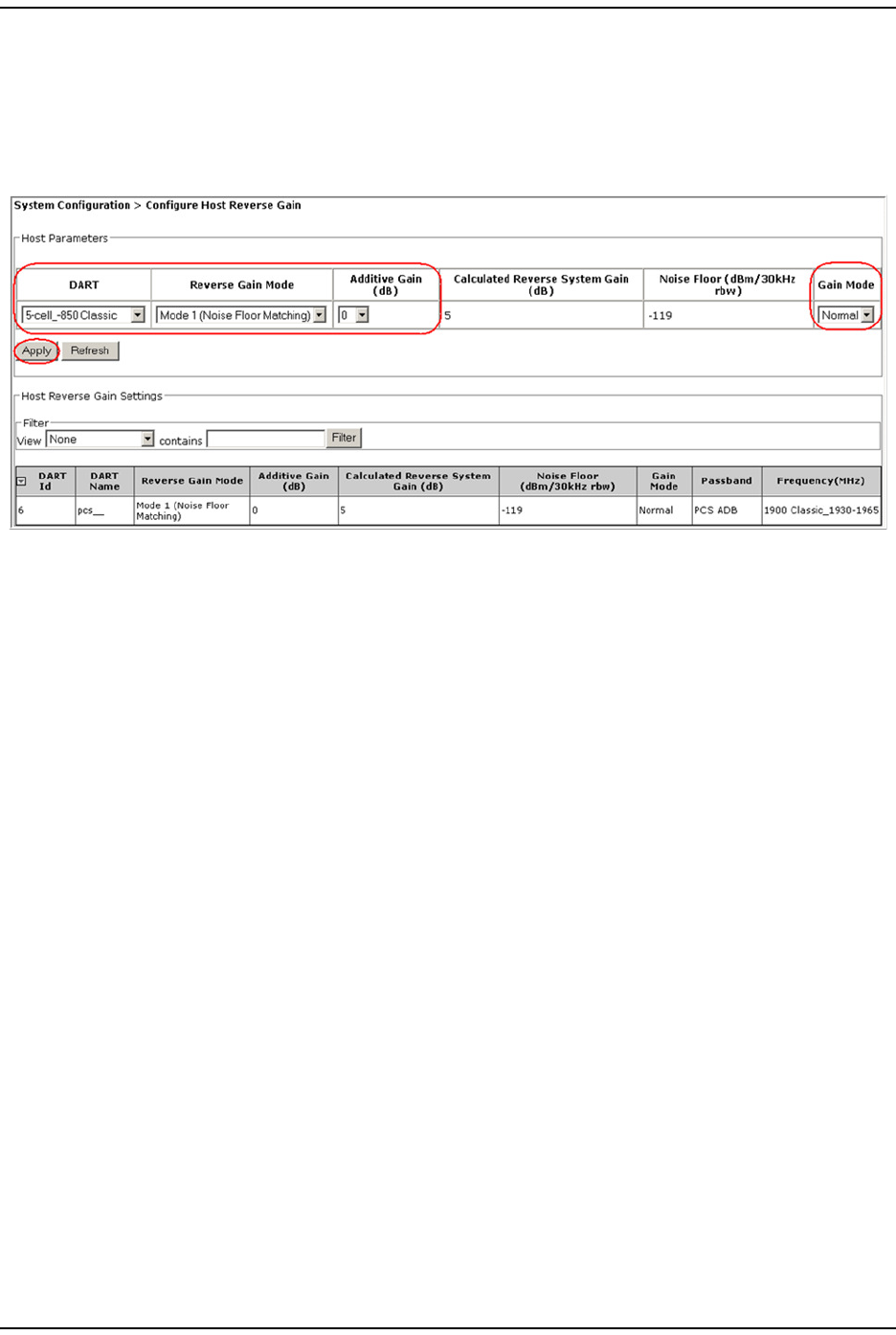
CONFIGURE HOST REVERSE GAIN
When setting the Reverse Gain value for the Host DART, t he following rules m ust be
observed:
•The Reverse Gain setting can be used t o overcom e RF int erfacing losses from t he
Host DART to the BTS/ BDA. I f you want unit y reverse path gain and the losses
to the BTS/ BDA are 20 dB, t hen t he Reverse Gain should be set to 20 dB.
•Sim ulcast changes t he actual REV gain level by 10log( n) where n = the num ber
of sim ulcast links. For exam ple, if REV gain is set to 10dB in a 2: 1 sim ulcast
configuration, the act ual REV gain is only 7dB ( 10dB - 3dB) . I f REV gain is set
to 20dB in a 4: 1 sim ulcast, the actual gain is 14dB ( 20dB - 6dB) .
Follow these st eps t o set t he Reverse Gain value for t he Host DART.
1To access t he Configure Host Reverse Gain page, in the Syst em Menu bar, click
System Configuration > Configure Host Reverse Gain.
2I n t he Host Parameters t able DART list , select t he Host DART that you want t o
configure. The DART Name colum n is populated with the user-defined nam e for
the select ed DART.
3I n t he Reverse Gain Mode list , select t he algorithm t hat should be used to add
at tenuat ion for a sim ulcast group to prevent clipping because of t oo st rong a
signal.
•Mode 1 (Noise Floor Matching)—optim izes the reverse path dynam ic range
bet ween sim ulcast nodes. For Prism / URU, t he gains are reduced by
10* log10( N) . This is the default for syst em s running Prism EMS 7.1.
•Mode 2 (Legacy Prism/URH)—reduces t he gain by 20* log10(N) . This is the
default set ting for system s upgraded from 6.0.
4Set the Additive Gain (dB) value to achieve t he required gain from the input t o t he
Rem ote Unit to the out put of the Host DART. The range is 0 to 31 dB.
I nit ial FlexWave Prism System Setup
FlexWave Prism Elem ent Managem ent Syst em 7.1 User Manual Page 89
ADCP- 77- 1 77 • Issue 1 • July 2011 © 2011 ADC Telecom m unicat ions, I nc.
5I n t he Gain Mode list, select one of the following:
•Normal—no increase to t he gain set ting.
•High—t he gain settings for Classic DARTs increase 2dB with a 1dB
im provem ent in the Noise Figure and the gain set ting for SuperDart s
increase by 6 dB wit h a 2dB im provem ent in the Noise Floor.
6Click Apply. The Host Parameters and Host Reverse Gain Settings t ables are updat ed
wit h the new configuration.
7Repeat St ep 2 t hrough St ep 6 for each Host DART.
Configure Host Reverse Gain
Page 90 FlexWave Pr ism Elem ent Managem ent System 7.1 User Manual
© 2011 ADC Telecommunications, Inc ADCP- 77-177 • I ssue 1 • July 2011
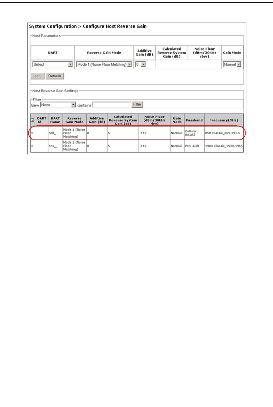
The Host Reverse Gain Settings t able has t he following colum ns.
•DART Id—identifies t he Host DART by t he slot in which it is installed, which can
be from 1 through 8.
•DART Name—identifies t he DART by it s user- defined nam e.
•Reverse Gain Mode—whet her t he Reverse Gain Mode is Mode 1 (Noise Floor Matching)
or Mode 2 (Legacy Prism/URH).
•Additive Gain (dB)—gain from the input t o t he Rem ot e Unit t o the out put of the
Host DART. The range is 0 t o 31 dB
•Calculated Reverse System Gain (dB)—shows t he end-to-end gain based on the
additive gain, gain m ode, and num ber of Rem ote Units in the sim ulcast group.
•Noise Floor (dBm/30kHz rbw)—shows t he noise level for t he configuration. The noise
floor is t he m easure of the signal created from the sum of all the noise sources.
•Gain Mode—whet her the Gain Mode is Normal or High.
•Passband—t ype of passband provided by t he DART.
•Frequency (MHz)—passband frequency of the DART.
I nit ial FlexWave Prism System Setup
FlexWave Prism Elem ent Managem ent Syst em 7.1 User Manual Page 91
ADCP- 77- 1 77 • Issue 1 • July 2011 © 2011 ADC Telecom m unicat ions, I nc.
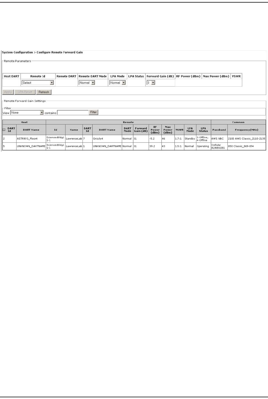
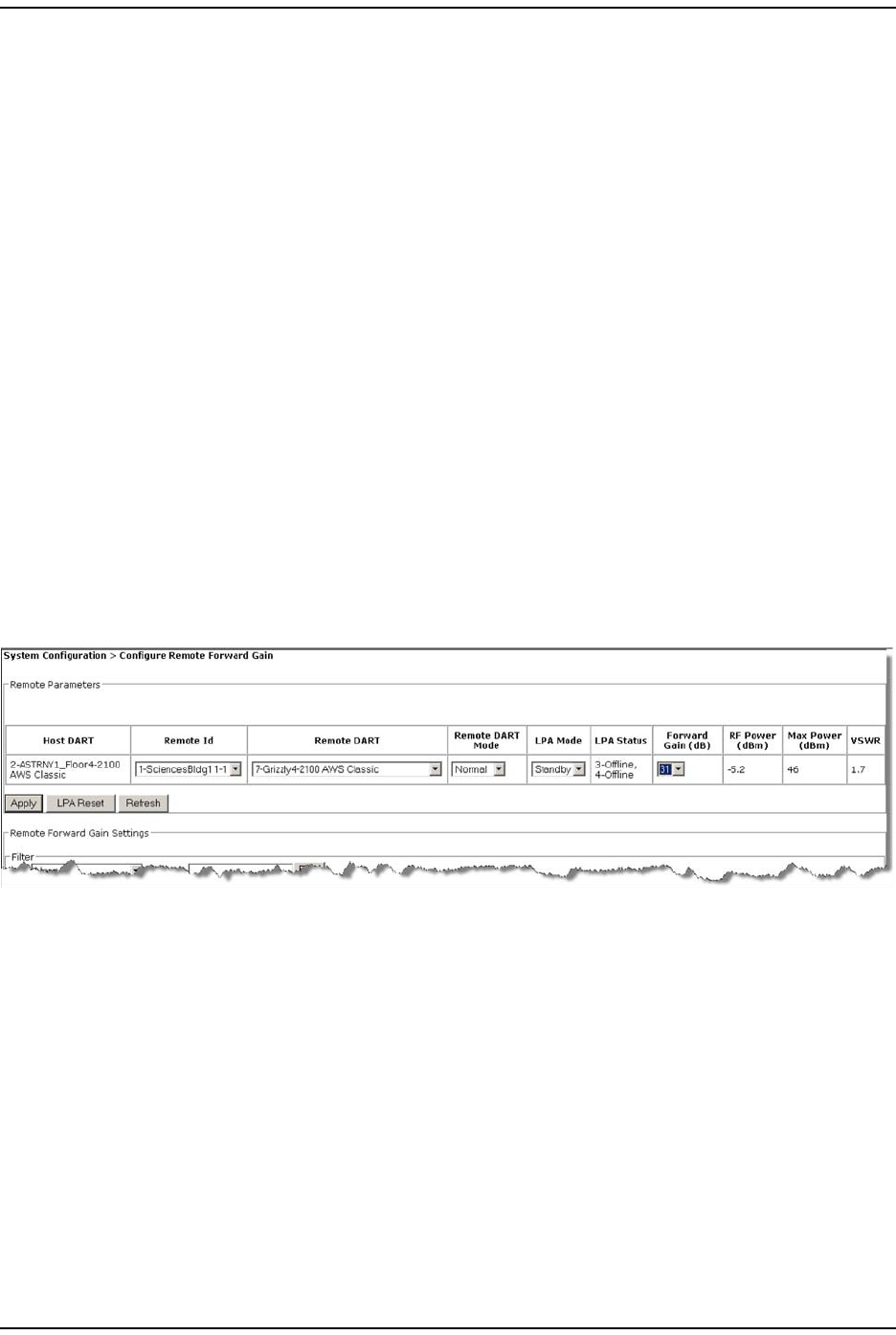
CONFIGURE REMOTE FORWARD GAIN
1To access the Configure Remote Forward Gain page, in the Syst em Menu bar, click
System Configuration > Configure Remote Forward Gain.
2I n t he Remote Parameters t able, do the following:
aUse t he Host DART colum n t o ident ify t he connect ed Host .
bI n t he Remote Id list , select t he Rem ote Unit for which you want to set the
Forward Gain.
cI n t he Remote DART Mode list , set t he DART m ode:
•Standby—forces the RF function t o be m uted in t he Host and it s linked
Rem ote Unit.
•Normal—allows t he syst em to operate norm ally ( RF function not forced t o
be m ut ed), assum ing all ot her syst em com ponents are in proper working
order. (Default set ting.)
dI n t he LPA Mode list, select Normal. A Prism Linear Power Am plifier ( LPA) is a
high qualit y broadband RF am plifier used for achieving Prism product -rat ed
power for t he Rem ot e Tx forward pat h spect rum RF. I n a dual- LPA syst em ,
bot h LPAs will have t he sam e LPA Mode set t ing.
•Standby—forces the RF function t o be m uted in t he Host and it s linked
Rem ote Unit. (Default set ting.)
•Normal—allows t he syst em to operate norm ally ( RF function not forced t o
be m ut ed), assum ing all ot her syst em com ponents are in proper working
order.
CAUTION! As soon as you set the LPA Operating Mode to Normal, RF transmission will start. Before
you set the LPA Operating Mode to Normal, make sure that the antenna has been
connected and the system is ready to transmit RF. For information on connecting the
antenna, refer to the ADC® FlexWave Prism Remote Unit Installation Guide
(ADCP-77-072).
Configure Rem ote Forward Gain
Page 92 FlexWave Pr ism Elem ent Managem ent System 7.1 User Manual
© 2011 ADC Telecommunications, Inc ADCP- 77-177 • I ssue 1 • July 2011
eI n t he Forward Gain list , select t he dB (0 t o 31) .
The Forward Gain is t he act ual gain, not attenuat ion, t hat will be applied to
the RF forward path signal ( where 0 = 0 dB gain, 1 = 1 dB gain, and so
fort h). The Forward Gain is based on the EI RP desired at t he antenna. You
therefore need t o know how m uch cable, insertion, and any other loss (such
as split ters) exist between t he Rem ote Unit and t he antenna. Set the Forward
Gain to achieve the required output power level t o m eet the EI RP of your RF
link budget.
Configure t he Host DART gain to achieve + 5dB so that full scale out put can
be achieved at t he Rem ot e. For further inform ation, refer to the FlexWave
Prism com m issioning guide.
fRefer t o t he following read-only fields for furt her inform at ion on the
select ed PRU/ URU:
•RF Power (dBm) colum n displays t he m easurem ent of the RF power for the
LPA ident ified in the LPA Num ber field.
NOTE: After a change in the DART Forward Gain, the EMS reflects the change in the RF Power
column within 25 seconds, or if the Refresh button is used, within 12 seconds.
•Max Power (dBm) colum n displays t he m axim um LPA power values.
•VSWR colum n displays t he Voltage St anding Wave Rat io (VSWR) for t he
LPA. An LPA VSWR Fault occurs if the VSWR m easurem ent exceeds t he
threshold, which is 3: 1.
I nit ial FlexWave Prism System Setup
FlexWave Prism Elem ent Managem ent Syst em 7.1 User Manual Page 93
ADCP- 77- 1 77 • Issue 1 • July 2011 © 2011 ADC Telecom m unicat ions, I nc.
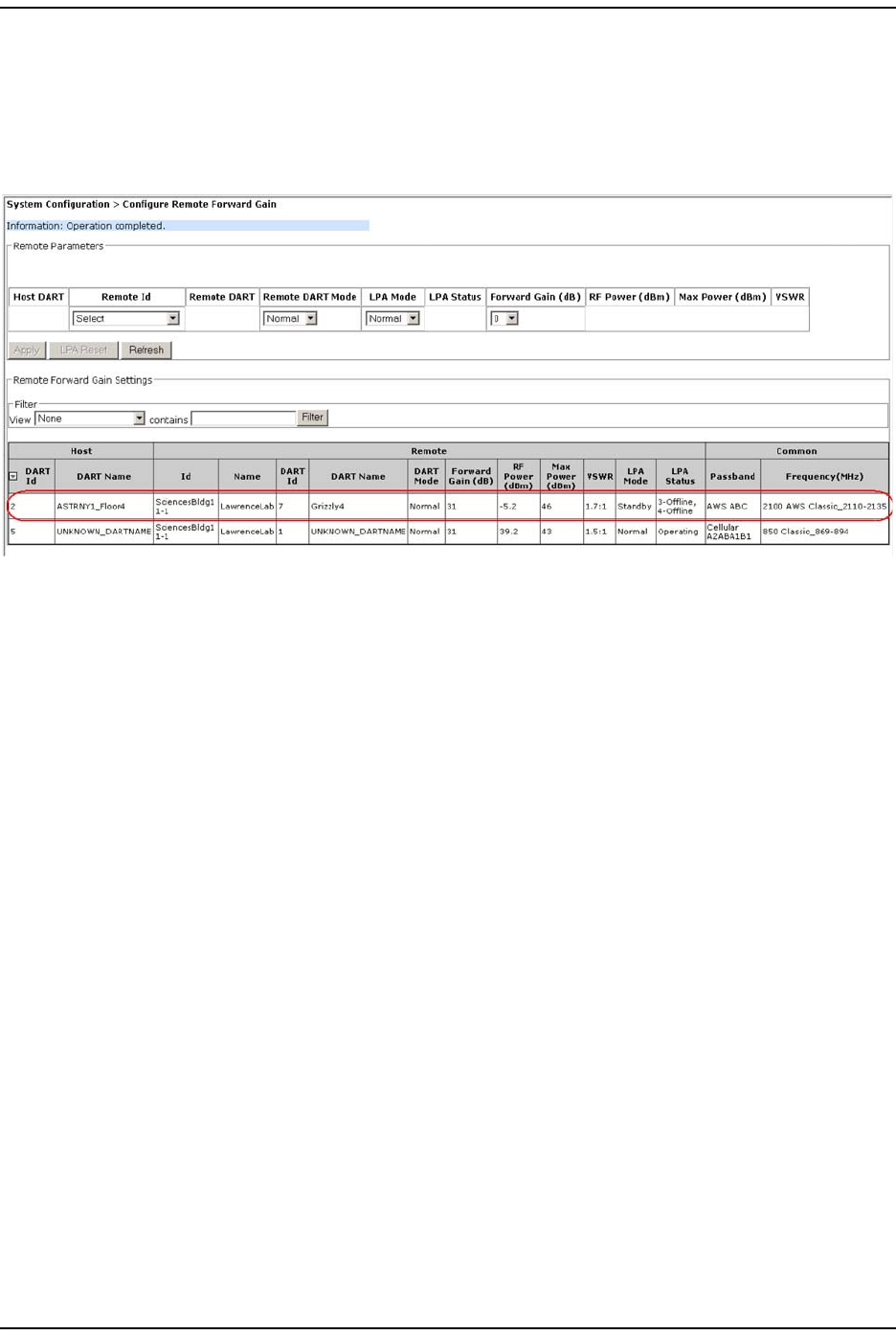
3Click Apply.
•Once t he syst em execut es t he com m and, an Operation completed m essage
displays.
•The Remote Forward Gain table at the bot t om of the page is updat ed wit h
the new set t ings.
4Repeat for each PRU/ URU DART.
For addit ional inform ation, refer t o t he following:
•For inform ation on the Remote Forward Gain Settings t able, see “Viewing the
Rem ote RF Report ” on page 109.
•For inform ation on the LPA Reset button, see “ Reset ting an LPA” on page 165.
Configure Reverse I nput Pow er Levels
Page 94 FlexWave Pr ism Elem ent Managem ent System 7.1 User Manual
© 2011 ADC Telecommunications, Inc ADCP- 77-177 • I ssue 1 • July 2011
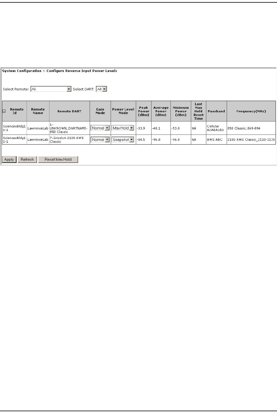
CONFIGURE REVERSE INPUT POWER LEVELS
NOTE: Digital power measurements are inaccurate when ALC is active.
1To access t he Configure Reverse Input Power Levels page, in the Syst em Menu bar,
click System Configuration > Configure Reverse Input Power Levels.
The read-Only colum ns in the table provide the following inform ation:
•Peak Power (dBm)—shows t he highest (peak) power level reached by t he DART
•Average Power (dBm)—shows the average power level reached by the DART
•Minimum Power (dBm)—shows t he m inim um power level reached by the DART
•Last Max Hold Reset Time—shows t he last t im e MAX Hold was reset .
•Passband—t ype of passband provided by the DART
•Frequency (MHz)—passband frequency of the DART
2I n t he Select Remote list , select t he PRU/ URU t hat you are configuring. The table
at the bott om of the page displays power level values for t he select ed Rem ote
Unit and it s DARTs.
3I n t he Select DART list , do one of the following:
•Select a specific DART t o configure. I f you select a specific DART, t he t able
at the bot tom of the page displays power level values for t he selected DART.
•Select All t o configure all the DARTs the sam e at t he sam e tim e. I f you select
All, t he t able at t he bottom of t he page displays power level values for t he
select ed Rem ot e Unit and all it s DARTs.
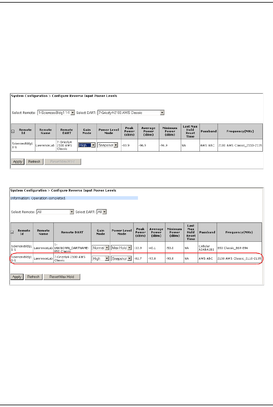
4I n t he Gain Mode list , set t he High Gain m ode to one of t he following:
•Normal—effect s t he attenuat ion of the tem perature com pensation algorithm
( default ) .
•High—does not effect the at t enuation of the tem perat ure com pensation
algorithm .
NOTE: When a Classic DART is in High Gain mode, the noise floor increases by 1 dBm. When a
Super DART is in High Gain mode, the noise floor increases by 4 dBm.
I nit ial FlexWave Prism System Setup
FlexWave Prism Elem ent Managem ent Syst em 7.1 User Manual Page 95
ADCP- 77- 1 77 • Issue 1 • July 2011 © 2011 ADC Telecom m unicat ions, I nc.
5I n t he Power Level Mode list, select one of t he following:
•Snapshot—provides a “ snap-shot” or current RF m easurem ent for t he
select ed Rem ot e Unit DART ( default set ting).
•Max Hold—retains t he m aximum values for peak and peak average, and the
m inim um values for m inim um average since the last Max Hold Reset.
Power Level Mode is disabled under any of the following condit ions:
•if the DART Operating m ode is set to Standby
•if the DART Pass Band (Timeslots) param eter is set to Undefined ( default)
6Click Apply.

Configure Reverse I nput Pow er Levels
Page 96 FlexWave Pr ism Elem ent Managem ent System 7.1 User Manual
© 2011 ADC Telecommunications, Inc ADCP- 77-177 • I ssue 1 • July 2011
7( Optional) I f you set t he Power Level Mode to Max Hold, you can click Reset Max Hold
to reset the Max Hold values.

FlexWave Prism Elem ent Managem ent Syst em 7.1 User Manual Page 97
ADCP- 77- 1 77 • Issue 1 • July 2011 © 2011 ADC Telecom m unicat ions, I nc.
PART I I I
SYSTEM MANAGEMENT

Page 98 FlexWave Pr ism Elem ent Managem ent System 7.1 User Manual
© 2011 ADC Telecommunications, Inc ADCP- 77-177 • I ssue 1 • July 2011
I nt entionally Blank Page

FlexWave Prism Elem ent Managem ent Syst em 7.1 User Manual Page 99
ADCP- 77- 1 77 • Issue 1 • July 2011 © 2011 ADC Telecommunications, Inc.
SYSTEM INFORMATION
Get I nform ation ................................................................................................................... 100
Accessing Syst em Reports ............................................................................................... 101
Viewing the Soft ware/ Firm ware Report ........................................................................ 101
Viewing the Hardware Invent ory Report ....................................................................... 102
Viewing the Net work Report ....................................................................................... 104
Viewing the Linked DARTs Report ................................................................................ 105
Viewing the Delay Report ........................................................................................... 106
Viewing the Fiber Report ............................................................................................ 107
Viewing the Host RF Repor t ........................................................................................ 108
Viewing the Rem ote RF Repor t .................................................................................... 109
Viewing the Alarm s Report ......................................................................................... 110
I FEU + RAU Report ................................................................................................... 111
Viewing the All Report ............................................................................................... 112
Downloading a Report ..................................................................................................... 113
Get Optics I nform at ion ......................................................................................................... 116
Get Logs ............................................................................................................................. 118
This sect ion tells you how to get and m anage syst em inform ation.
Topics Page
Get I nform at ion
Page 100 FlexWave Prism Elem ent Managem ent Syst em 7.1 User Manual
© 2011 ADC Telecommunications, Inc ADCP- 77-177 • I ssue 1 • July 2011
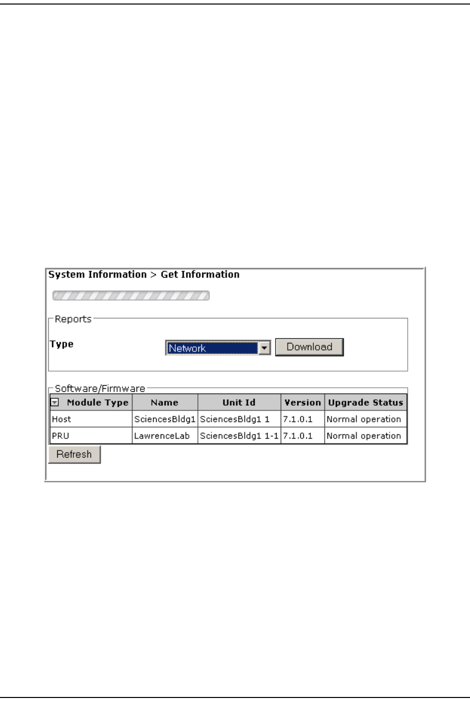
GET INFORMATION
The Get Information page allows you t o view system inform ation on one page. You
can also view and download nine individual report s.
To access the Get Information page, in t he Syst em Menu bar, click System Information >
Get Information.
The following graphic shows t he default page in which Type is set to System Inventory.
The Get Information page has t he following elem ent s:
•Type list —allows you to select which report you want to view.
•Download butt on—downloads select ed report to an attached PC. See
“ Downloading a Report” on page 113.
NOTE: The gray and white status bar at the top of the page indicates that the EMS is accessing
the requested report. You do not need to select Download to see the report in the GUI.
Syst em Inform at ion
FlexWave Prism Elem ent Managem ent Syst em 7.1 User Manual Page 101
ADCP- 77- 1 77 • Issue 1 • July 2011 © 2011 ADC Telecom m unicat ions, I nc.
Accessing System Reports
You use the Type list in the Reports panel t o select t he t ype of report t hat you want
to download. The following sect ions describe the report s t hat you can view and
download.
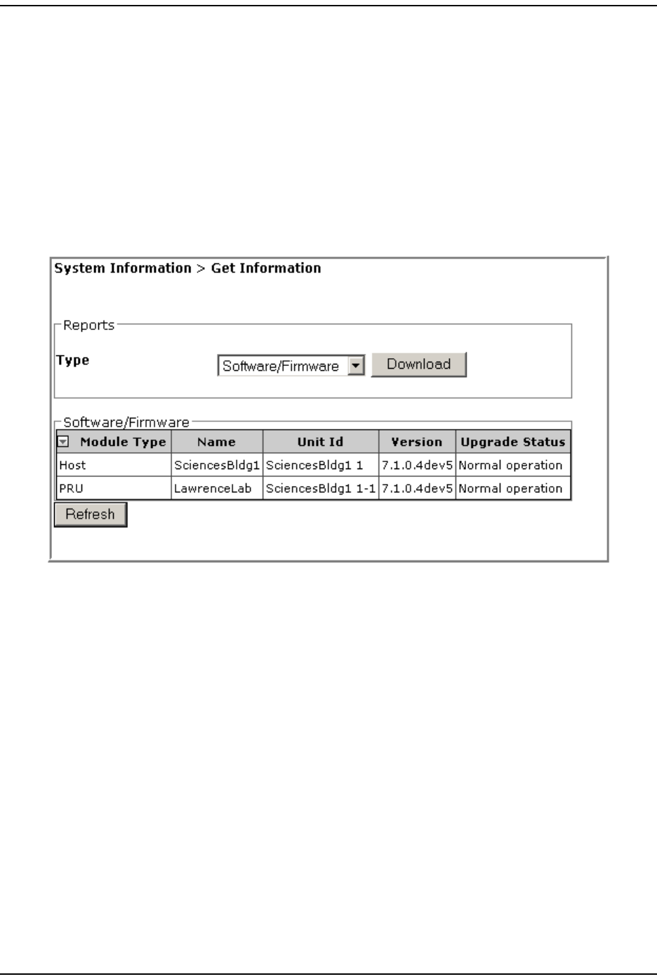
Viewing the Software/Firmware Report
To access t he Software/Firmware report , in the Syst em Menu bar, click System
Information > Get Information, and then in the Reports panel Type list, select
Software/Firmware. ( This is t he default set ting.)
The Software/Firmware table pr ovides t he following inform ation:
•Module Type—type of unit ( Host , PRU, or URU) .
•Name—user- assigned nam e for t he unit.
•Unit Id—identifies t he unit within the syst em ; see “Unit I dentification” on
page 43.
•Version—version of inst alled software/ firm ware.
•Upgrade Status—t he following st at es can be seen. However, with t he except ion of
Normal operation and Upgraded, t he states occur very quickly during the
corresponding act ion and are rarely viewed.
–Normal operation
–Upgrading
–Upgrading reboot
–Committing
–Aborting
–Recovering
– Upgraded.
Get I nform at ion
Page 102 FlexWave Prism Elem ent Managem ent Syst em 7.1 User Manual
© 2011 ADC Telecommunications, Inc ADCP- 77-177 • I ssue 1 • July 2011
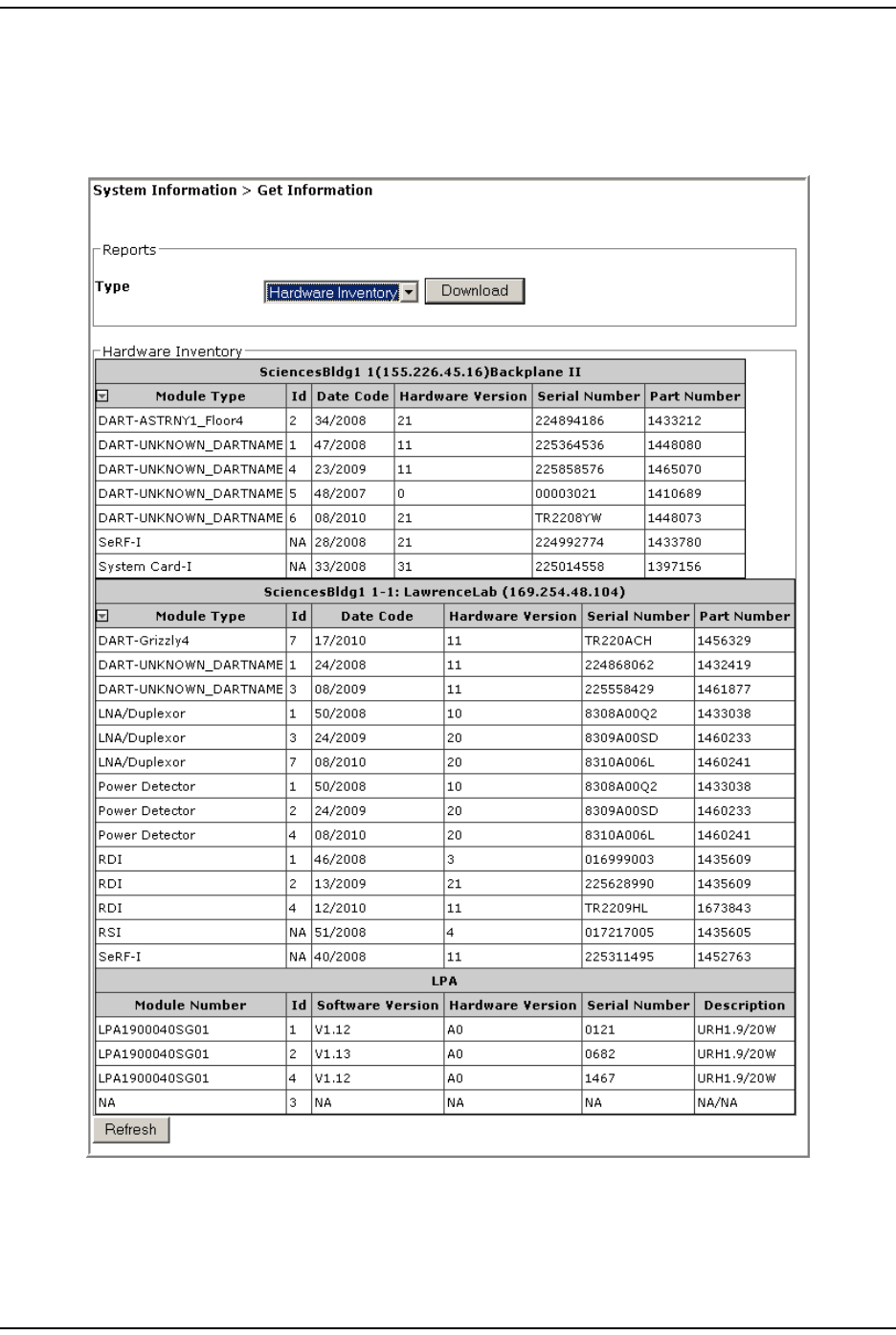
Viewing the Hardware Inventory Report
To access t he Hardware Inventory report for t he Host and Rem ot e Unit( s) , in the
System Menu bar, click System Information > Get Information, and t hen in the Reports
panel Type list , select Hardware Inventory.
Syst em Inform at ion
FlexWave Prism Elem ent Managem ent Syst em 7.1 User Manual Page 103
ADCP- 77- 1 77 • Issue 1 • July 2011 © 2011 ADC Telecom m unicat ions, I nc.
The Hardware Inventory page has separate t ables for each Host and Rem ote Unit in
the syst em . For each Rem ot e Unit list ed, there is also a corresponding LPA t able.
Each unit is identified by nam e and I P address in a t it le bar at the top of the table.
Each t able provides t he following inform ation:
•Module Type—ident ifies t he m odule by t ype, such as Syst em Card, DART, SeRF
( not used in t he LPA table) .
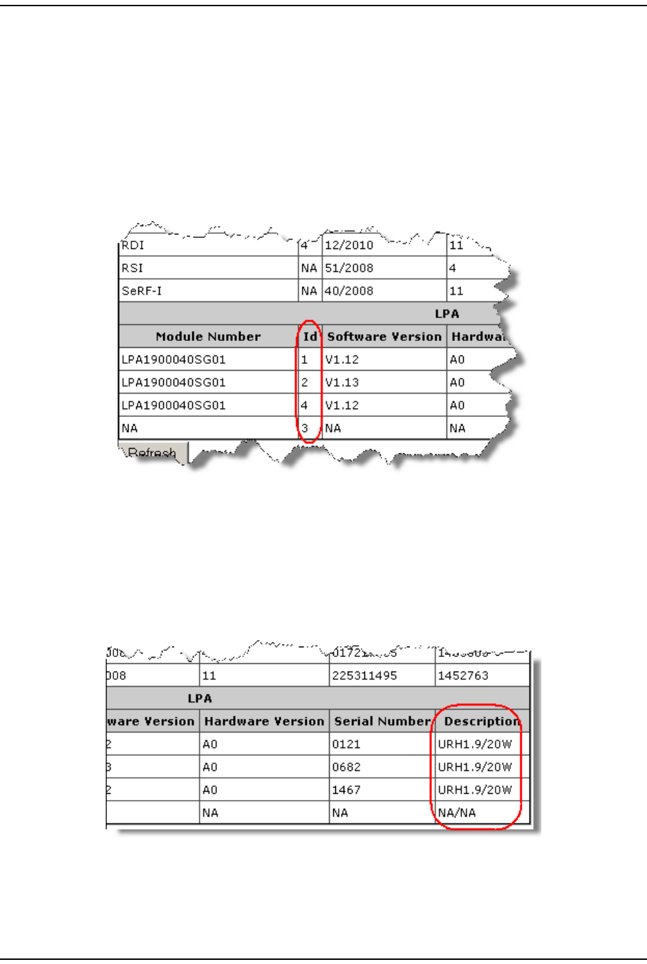
•Module Number (LPA t able only)—ident ifies t he LPA.
•Id—applicable t o t he DARTs and LPAs only; for furt her inform at ion see “ RF
Module Capabilit ies and GUI Represent at ion” on page 21.
•Date Code—dat e code for t he m odule.
•Hardware Version—release version num ber for the m odule.
•Serial Number—serial num ber for the m odule assigned during m anufact uring.
•Part Number—Part Num ber for t he m odule assigned during m anufact uring ( not
applicable t o t he LPA) .
•Description (LPA only) —band type of LPA/ LPA power in Watts.
Get I nform at ion
Page 104 FlexWave Prism Elem ent Managem ent Syst em 7.1 User Manual
© 2011 ADC Telecommunications, Inc ADCP- 77-177 • I ssue 1 • July 2011
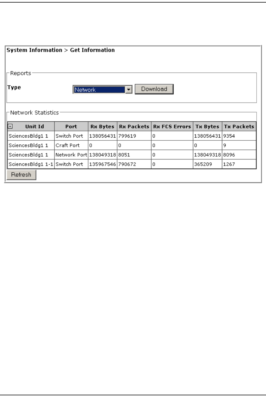
Viewing the Network Report
To access the Network report, in the Syst em Menu bar, click System Information > Get
Information, and then in t he Reports panel Type list, select Network.
The Network Statistics t able provides t he following inform at ion:
•Unit Id—identifies t he unit within the syst em ; see “Unit I dent ificat ion” on
page 43.
•Port—ident ifies t he port
– Host ports can be any of the following:
Net work Port
Craft Port
Switch Port
– Rem ote Unit port is indicat ed only as a Switch Port
NOTE: A Switch Port is the CPU’s connection to the Ethernet switch that in turn communicates to
the fibers. This shows how much traffic the unit is generating and consuming.
•Rx Bytes—count of Receive Byt es.
•Rx Packets—count of Receive Packet s.
•RX FCS Errors—count of Receive FCS Errors.
•Tx Bytes—count of Transm it Byt es.
•Tx Packets—count of Transm it Packet s.

Syst em Inform at ion
FlexWave Prism Elem ent Managem ent Syst em 7.1 User Manual Page 105
ADCP- 77- 1 77 • Issue 1 • July 2011 © 2011 ADC Telecom m unicat ions, I nc.
Viewing the Linked DARTs Report
To access t he Linked DARTs report , in t he System Menu bar, click System Information >
Get Information, and then in the Reports panel Type list , select Link.
The Linked DARTs t able provides the following inform at ion:
•Host colum ns—ident ifies t he Host and its elem ents
–DART Id—num ber of t he Host slot in which t he DART is inst alled
–DART Name—user- defined nam e for t he Host DART
–SFP Id—port num ber of physical optical port where Host - Rem ote optical fiber
is connected on the Host .
–SFP Name—user- defined nam e for the Optics port .
•Remote colum ns—identifies t he Rem ot e and it s elem ents
–Id—Unit I D of PRU/ URU based upon layered address; see “ Unit
I dent ification” on page 43
–Name—user- defined label for t he PRU/ URU
–SFP Id—identificat ion (I d) of Rem ote side SFP connected t oward the Host
DART (can be from 1 t hrough 8)
–SFP Name—user- defined nam e for the Optics port
–DART Id—PRU/ URU slot num ber in which t he DART is inst alled
–DART Name—user- defined nam e for t he Rem ot e DART
–Timeslots—num ber of tim eslot s assigned to the link.
•Common colum ns—identify configuration set t ings t hat are com m on t o the Host
and connect ed Rem ote( s)
–Passband—t ype of passband provided by t he DART
–Frequency—passband frequency of the DART
–Diversity—whet her DART is configured as Diversity or Non Diversity. For t his
release, t his will always be Non Diversity.

Get I nform at ion
Page 106 FlexWave Prism Elem ent Managem ent Syst em 7.1 User Manual
© 2011 ADC Telecommunications, Inc ADCP- 77-177 • I ssue 1 • July 2011
Viewing the Delay Report
To access the Linked DARTs Delay report , in the Syst em Menu bar, click System
Information > Get Information, and then in the Reports panel Type list , select Delay.
The Linked DARTs Delay table provides t he following inform ation:
•Host colum ns—ident ifies the Host in the link
–DART Id—num ber of t he Host slot in which t he DART is inst alled
–DART Name—user- defined nam e for the Host DART.
•Remote colum ns—identifies t he Rem ot e and it s elem ents
–Id—Unit I D of PRU/ URU based upon layered address; see “ Unit
I dent ification” on page 43
–Name—user- defined label for t he PRU/ URU
–DART Id—PRU/ URU slot num ber in which t he DART is inst alled
–DART Name—user- defined nam e for the Rem ot e DART
–Forward Delay ( s) —user request ed FWD RF pat h delay in m icroseconds
–Reverse Delay ( s) —user requested REV RF path delay in m icroseconds.
•Common colum ns—identify configuration set t ings t hat are com m on t o the Host
and connect ed Rem ot e(s)
–Passband—t ype of passband provided by the DART
–Frequency (MHz)—passband frequency of the DART.
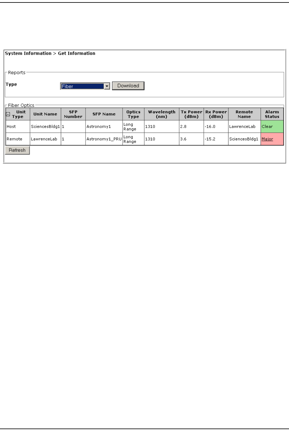
Syst em Inform at ion
FlexWave Prism Elem ent Managem ent Syst em 7.1 User Manual Page 107
ADCP- 77- 1 77 • Issue 1 • July 2011 © 2011 ADC Telecom m unicat ions, I nc.
Viewing the Fiber Report
To access t he Fiber Optics report , in the Syst em Menu bar, click System Information >
Get Information, and then in the Reports panel Type list , select Fiber.
The Fiber Optics table provides t he following inform at ion:
•Unit Type—what the unit is, such as Host or Rem ot e.
•Unit Name—Unit I D of t he unit based upon layered address; see “ Unit
I dent ification” on page 43.
•SFP Number—Optical port num ber, from 1 to 8.
•SFP Name—nam e assigned t o t he Opt ical port ; default SFP Name is
UNKNOWN_SFPNAME.
• Optics Type
–LongRange—26 dB
–IntermediateRange—18 dB) .
•Wavelength (nm)—wave length transm itt ed through this port :
– Non-duplex and WDM configurations: 1550 nm fw d, 1310 nm rev
– CWDM configurat ions can be one of eight wavelengt hs: 1470 nm , 1490 nm ,
1510 nm , 1530 nm , 1550 nm , 1570 nm , 1590 nm , and 1610 nm .
•Tx Power (dBm)—launch power level in dBm of forward path signal. The m inim um
FWD launch power is - 2 dBm , and the m axim um is 3 dBm .
•Rx Power (dBm)—receive power level in dBm of reverse path signal, which
incorporat es the launch power of the Rem ot e Unit SFP plus all optical losses
( insertion losses, fiber cable loss, and so forth) .
•Remote Name—nam e of t he Rem ote connect ed to this Opt ical port .
•Alarm Status—whether an alarm is act ive. I f an alarm is act ive, there will be a
Minor or Major link that you click to open a dialog that defines t he active alarm ,
as described in “ Viewing Alarm Details” on page 45. The background color of
the Alarm Status cell also indicates t he alarm level ( see “Alarm Color Codes” on
page 44) .
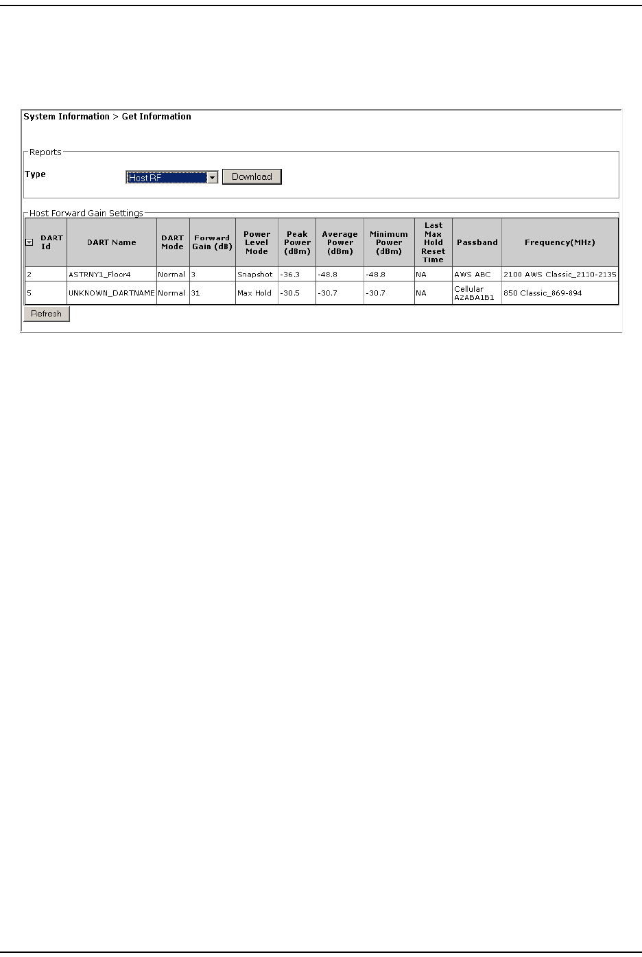
Get I nform at ion
Page 108 FlexWave Prism Elem ent Managem ent Syst em 7.1 User Manual
© 2011 ADC Telecommunications, Inc ADCP- 77-177 • I ssue 1 • July 2011
Viewing the Host RF Report
To access t he Host Forward Gain Settings report, in t he Syst em Menu bar, click System
Information > Get Information, and then in the Reports panel Type list , select Host RF.
The Host Forward Gain Settings t able provides t he following inform at ion.
•DART Id—num ber of t he Host slot in which t he DART is inst alled
•DART Name—user- defined nam e for the Host DART
•DART Mode—identifies t he RF funct ion
–Standby—RF funct ion is m ut ed in the Host and its linked Rem ote Unit.
–Normal—RF function not forced t o be m ut ed, allows the system to operate
norm ally
•Fwd Gain (db)—Forward Gain in decibels assigned to the DART
•Power Level Mode—Host DART I nput Power Level Mode:
–Snapshot—provides a “ snap-shot” or current RF m easurem ent for t he
selected Rem ote DART (default set t ing) .
–Max Hold—retains t he m axim um values for peak and peak average, and the
m inim um values for m inim um average since t he last Max Hold Reset.
NOTE: The Power Level Mode is disabled if the:
• DART Operating mode is set to Standby
• DART Pass Band (Timeslots) parameter is set to Undefined (default)
• DART Diversity Status is set to Diversity.
•Peak Power (dBm)—highest level of power experienced on the DART Forward link.
•Average Power (dBm)—average power experienced on t he DART Forward link.
•Minimum Power (dBm)—average m inim um power experienced on the DART
Forward link.
•Last Max Hold Reset Time—tim e that Max Hold was last reset .
•Passband—t ype of passband provided by t he DART.
•Frequency (MHz)—passband frequency of the DART

Syst em Inform at ion
FlexWave Prism Elem ent Managem ent Syst em 7.1 User Manual Page 109
ADCP- 77- 1 77 • Issue 1 • July 2011 © 2011 ADC Telecom m unicat ions, I nc.
Viewing the Remote RF Report
To access t he Remote Forward Gain Settings report, in t he Syst em Menu bar, click System
Information > Get Information, and then in the Reports panel Type list , select Remote RF.
The Remote Forward Gain Settings t able provides t he following inform ation:
•Host colum ns—identifies t he Host in the link
–DART Id—num ber assigned by t he EMS to the Host DART for ident ificat ion
purposes
–DART Name—user- defined nam e for t he DART.
•Remote colum ns—identifies t he Rem ot e and it s elem ents
–DART Id—Unit I D of PRU/ URU based upon layered address; see “Unit
I dent ification” on page 43
–DART Name—user- defined label for t he PRU/ URU
–DART Mode—how RF funct ions on t hat DART
•Standby—forces the RF function t o be m uted in t he Host and it s linked
Rem ote.
•Normal—allows t he syst em to operate norm ally ( RF function not forced t o
be m ut ed), assum ing all ot her syst em com ponents are in proper working
order. (Default set ting.)
–Forward Gain (db)—act ual gain, not at t enuation, applied t o the RF forward pat h
signal ( where 0 = 0 dB gain, 1 = 1 dB gain, and so fort h)
–RF Power (dBm)—estim at ed power level based upon input level and gain.
–Max Power (dBm)—the m axim um LPA power values
–VSWR—the Volt age Standing Wave Ratio ( VSWR) for t he LPA. An LPA VSWR
Fault occurs if the VSWR m easurem ent exceeds t he threshold, which is 3: 1.
–LPA Mode—t he LPA Mode, which can be Normal or Standby
–LPA Status—t he LPA st atus. I n case of dual LPA, it will indicat e t he value for
bot h LPAs as eit her 1-Offline or 2-Operating.
•Passband—t ype of passband provided by t he DART
•Frequency (MHz)—passband frequency of t he DART