ADC Telecommunications PSM0804A FlexWave™ Prism - Cellular 40 Watt User Manual 3
ADC Telecommunications Inc FlexWave™ Prism - Cellular 40 Watt Users Manual 3
Contents
- 1. Users Manual 1
- 2. Users Manual 2
- 3. Users Manual 3
- 4. Users Manual 4
Users Manual 3

Get I nform at ion
Page 110 FlexWave Prism Elem ent Managem ent System 7.1 User Manual
© 2011 ADC Telecommunications, Inc ADCP-77- 177 • I ssue 1 • July 2011
Viewing the Alarms Report
To access the Current Alarms report, in the Syst em Menu bar, click System Information
> Get Information, and then in the Reports panel Type list, select Alarms.
The Current Alarms table provides the following inform ation:
•Severity—whet her alarm is classified as Maj or or Minor.
•Ack’d—whether the alarm has been acknowledged, as indicat ed by a
checkm ark.
•Alarm Code—syst em -assigned alarm code. See “ Troubleshoot ing Alarm s” on
page 185 or use t he “ I ndex of Alarm s” on page 313 to find t he page num ber
for a specific alarm description, which includes t he alarm code.
•Alarm Name—descriptive nam e of alarm .
•Timestamp—dat e and tim e when the alarm occurred (YYYY:MM:DD:HH:MM:SS)
•Unit Id—ident ifies the unit wit hin t he syst em ; see “ Unit I dentificat ion” on
page 43.
•Unit Type—what t he unit is, such as Host or Rem ot e
•Unit Name—nam e assigned t o the unit
•Module—type of m odule wit hin the specified unit t hat is experiencing t he alarm
( SeRF, DART, Power Det ect or, SFP)
•Module Name—user- assigned nam e for t he m odule t hat assist s in ident ifying
m odules when t roubleshoot ing
•RF Band—type of passband provided by t he DART ( if applicable)
Syst em I nform at ion
FlexWave Prism Elem ent Managem ent Syst em 7.1 User Manual Page 111
ADCP- 77- 177 • I ssue 1 • July 2011 © 2011 ADC Telecom m unicat ions, I nc.
•Extended Info—link t hat provides furt her inform at ion on the alarm , including
troubleshoot ing inform at ion.
IFEU + RAU Report
The IFEU + RAU report pert ains t o an I nt erReach Spectrum system and is not
applicable t o t his release.
Get I nform at ion
Page 112 FlexWave Prism Elem ent Managem ent System 7.1 User Manual
© 2011 ADC Telecommunications, Inc ADCP-77- 177 • I ssue 1 • July 2011
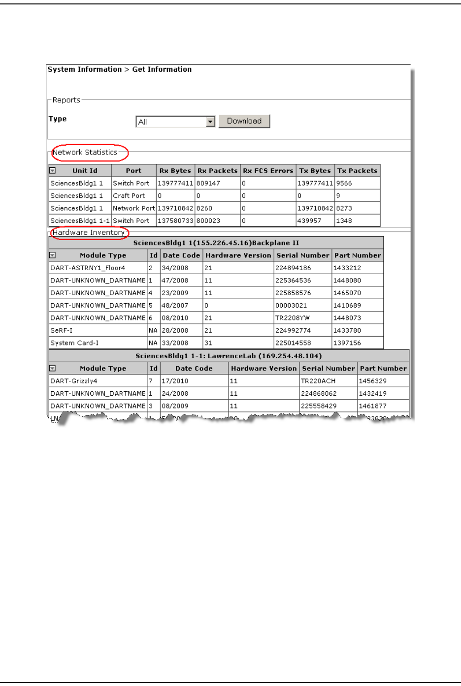
Viewing the All Report
The All Report consolidat es all available report s into a single web page.
Syst em I nform at ion
FlexWave Prism Elem ent Managem ent Syst em 7.1 User Manual Page 113
ADCP- 77- 177 • I ssue 1 • July 2011 © 2011 ADC Telecom m unicat ions, I nc.
Downloading a Report
CAUTION! The All Report or Analog Units Report can take several minutes to download.
You can download the reports t o your laptop in Windows Excel form at .
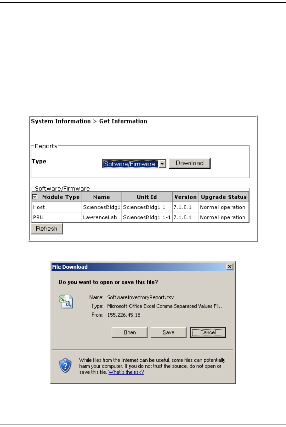
Do t he following t o download a report t o your com puter:
1I n the Syst em Menu bar, click System Information > Get Information.
2On t he Get Information page, in t he Reports panel Type list, select t he nam e of the
report that you want to download.
3Click Download.
4I n t he File Download window, click Save.
Get I nform at ion
Page 114 FlexWave Prism Elem ent Managem ent System 7.1 User Manual
© 2011 ADC Telecommunications, Inc ADCP-77- 177 • I ssue 1 • July 2011
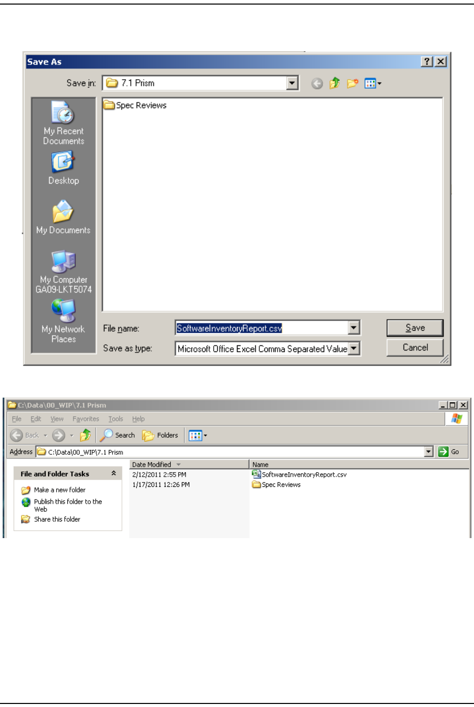
5I n t he Save As window, navigat e to where you want the report file saved, and
then click Save.
The file is saved as specified.

Syst em I nform at ion
FlexWave Prism Elem ent Managem ent Syst em 7.1 User Manual Page 115
ADCP- 77- 177 • I ssue 1 • July 2011 © 2011 ADC Telecom m unicat ions, I nc.
6Go t o the directory where t he file was saved t o open t he file.
NOTE: While Excel is often used to view this file, Excel uses characters such as hyphens and
slashes to create formulas. If discrepancies are seen in this report, use a text editor to
verify the report’s content.
Get Optics I nform ation
Page 116 FlexWave Prism Elem ent Managem ent System 7.1 User Manual
© 2011 ADC Telecommunications, Inc ADCP-77- 177 • I ssue 1 • July 2011
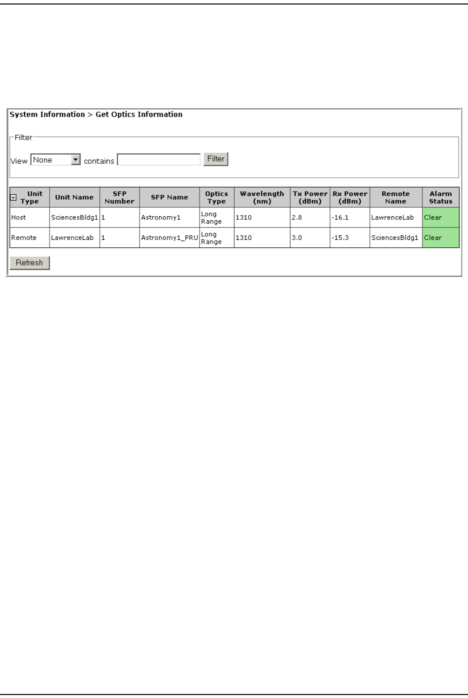
GET OPTICS INFORMATION
The Get Optics Information page allows you t o view inform ation on t he fiber.
To access the Get Optics Information page, in t he Syst em Menu bar, click System
Information > Get Optics Information.
The Filter panel has t he following elem ent s:
•View list —allows you t o select a filt er to be applied t o the page
•contains box—allows you t o ent er filt er crit eria
•Filter button—click t o apply t he filt er
The Get Optics Information t able has the following elem ents:
•Unit Type—whether the unit is a Host or Rem ot e
•Unit Name—user defined nam e of t he unit
•SFP Number—syst em assigned num ber ( from 1 t o 8) for t he Optical port s
•SFP Name—user ent ered port nam e or UNKNOWN_SFPNAME, which indicates that a
nam e has not been entered.
• Optics Type
–LongRange—26 dB
–IntermediateRange—18 dB) .

Syst em I nform at ion
FlexWave Prism Elem ent Managem ent Syst em 7.1 User Manual Page 117
ADCP- 77- 177 • I ssue 1 • July 2011 © 2011 ADC Telecom m unicat ions, I nc.
•Wavelength (nm)—num ber displayed is t he wavelengt h transm it t ed through this
port :
– Non- duplex and WDM configurat ions
1550 nm fwd
1310 nm rev
– CWDM configurations can be one of eight wavelengt hs:
•Tx Power (dBm)—launch power level in dBm of forward pat h signal. The m inim um
FWD launch power is - 2 dBm , and t he m axim um is 3 dBm .
•Rx Power (dBm)—Receive power level in dBm of reverse pat h signal, which
incorporates the launch power of t he Rem ot e Unit SFP plus all optical losses
( insert ion losses, fiber cable loss, and so fort h) .
•Remote Name—nam e of the Rem ot e connected t o t his Optics port .
•Alarm Status—whet her an alarm is active. I f an alarm is act ive, there will be a
Minor or Major link t hat you click to open a dialog that defines the act ive alarm ,
as described in “ Viewing Alarm Det ails” on page 45. The background color of
the Alarm Status cell also indicat es t he alarm level (see “ Alarm Color Codes” on
page 44) .
1470 nm 1550 nm
1490 nm 1570 nm
1510 nm 1590 nm
1530 nm 1610 nm
Get Logs
Page 118 FlexWave Prism Elem ent Managem ent System 7.1 User Manual
© 2011 ADC Telecommunications, Inc ADCP-77- 177 • I ssue 1 • July 2011
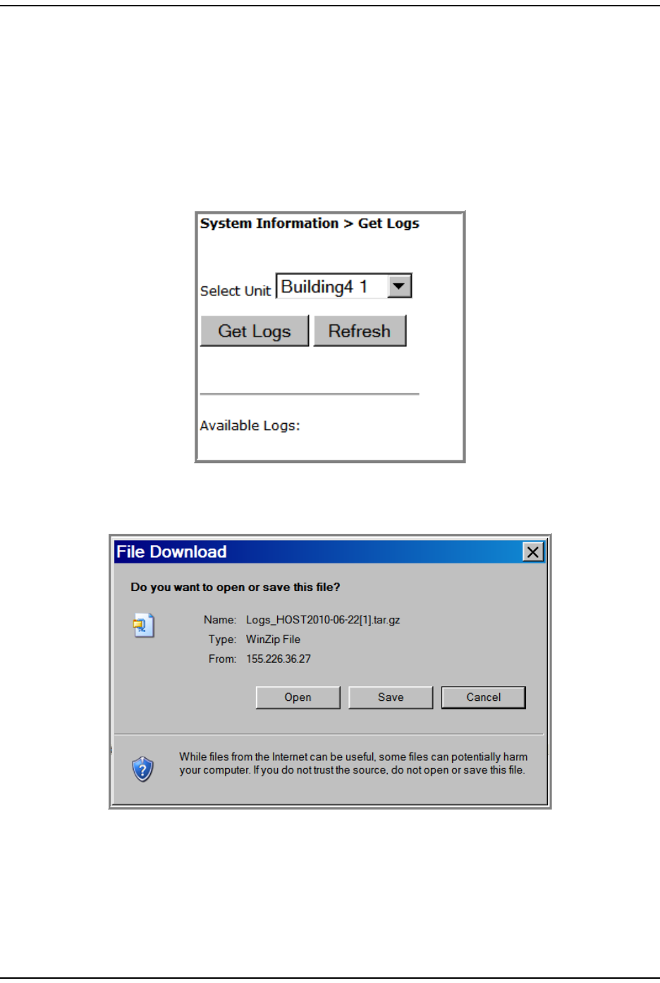
GET LOGS
The Get Logs page allows you to save com pressed t ar archive files of Prism logs.This
featur e is prim arily used by ADC personnel when t roubleshoot ing a syst em .
However, you should know how t o creat e a log so you can em ail the log t o ADC if
request ed t o do so.
1To access the Get Logs page, in t he System Menu bar, click System Information >
Get Logs.
2Click Get Logs.
3I n t he File Download dialog, click Save.
Syst em I nform at ion
FlexWave Prism Elem ent Managem ent Syst em 7.1 User Manual Page 119
ADCP- 77- 177 • I ssue 1 • July 2011 © 2011 ADC Telecom m unicat ions, I nc.
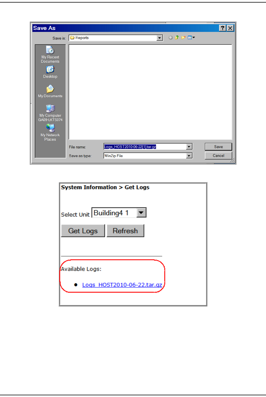
4I n t he Save As dialog, navigat e t o where you want t o save the log file.
Aft er a log has been creat ed, it is list ed as an Available Log in t he Get Logs page.
5I n Windows, navigat e t o where you saved the log zip file on your hard drive.
6Double- click on t he t ar file to access the logs.

Get Logs
Page 120 FlexWave Prism Elem ent Managem ent System 7.1 User Manual
© 2011 ADC Telecommunications, Inc ADCP-77- 177 • I ssue 1 • July 2011
I nt ent ionally Blank Page

FlexWave Prism Elem ent Managem ent Syst em 7.1 User Manual Page 121
ADCP- 77- 177 • I ssue 1 • July 2011 © 2011 ADC Telecommunications, Inc.
SYSTEM MANAGEMENT
Moving or Reconfiguring Fibers .............................................................................................. 122
Edit t he Properties of All Unit s in t he System ........................................................................... 123
Reset All Unit s t o Fact ory Default ........................................................................................... 124
Backing Up a Syst em Configurat ion ........................................................................................ 126
Restoring a Backed Up System Configuration ........................................................................... 128
Perform Syst em Test ............................................................................................................ 131
Schedule Syst em Test .......................................................................................................... 135
Schedule Syst em Test s by Dat e and Tim e .......................................................................... 135
Disable a Scheduled Syst em Test ...................................................................................... 137
Set SNMP Trap Managers ...................................................................................................... 138
Adding an SNMP Trap Manager ......................................................................................... 139
Modifying an SNMP Trap Manager ..................................................................................... 141
Delet ing an SNMP Trap Manager ....................................................................................... 142
Set up SNMP ....................................................................................................................... 144
Activate Optional Features .................................................................................................... 145
The EMS views and param et ers discussed in t his section affect the entire Prism
syst em , as opposed t o affecting an individual unit or m odule.
Topics Page

Moving or Reconfiguring Fibers
Page 122 FlexWave Prism Elem ent Managem ent System 7.1 User Manual
© 2011 ADC Telecommunications, Inc ADCP-77- 177 • I ssue 1 • July 2011
MOVING OR RECONFIGURING FIBERS
I f you need t o m ove or reconfigure fibers during t roubleshoot ing, follow t he st eps
below.
1Move Host SFPs and fibers to t heir new locations.
2Do t he following if a previously filled SFP posit ion is now em pty:
aThere will st ill be a GUI represent at ion of a Rem ot e on t hat SFP. To rem ove
this ghost represent at ion, follow the st eps in “ Clear All Disconnect Alarm s”
on page 184.
bTo delete fiber and SFP alarm s at t ribut ed t o the abandoned SFP positions,
follow t he st eps in “ Clear Current Alarm s” on page 170.
3 Com ple t e t his st ep only for m oved DARTs now in a n alarm e d st ate. I f
the configurat ion of a Rem ot e Unit DART originally connect ed t o an SFP does
not m atch t he configurat ion of the DART m oved t o t he SFP, the new DART will
have an alarm st at e such as Module Missing Fault or DART Hardware Mismatch. I n this
inst ance, follow the st eps in “ Clearing DART Configurat ions” on page 161 to
clear the configurat ion of t he DART in the alarm ed st at e.
Syst em Managem ent
FlexWave Prism Elem ent Managem ent Syst em 7.1 User Manual Page 123
ADCP- 77- 177 • I ssue 1 • July 2011 © 2011 ADC Telecom m unicat ions, I nc.
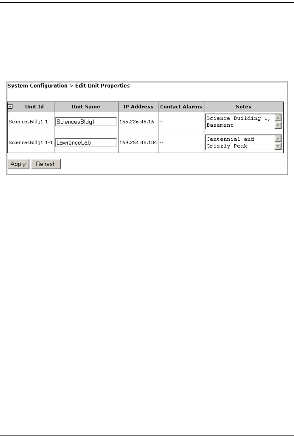
EDIT THE PROPERTIES OF ALL UNITS IN THE SYSTEM
The Edit Unit Properties page t hat is accessible t hrough the Syst em Menu bar allows
you t o edit basic inform ation and opt ionally provide not es for all t he unit s in the
syst em at one tim e.
To access the Edit Unit Properties page, in t he Syst em Menu bar, click System
Configuration > Edit Unit Properties.
The Edit Unit Properties page has the following elem ent s, where each row in the Edit
Unit Properties t able correspond t o the unit identified in the Unit Id colum n.
•Unit Id colum n—ident ifies t he unit wit hin t he system ; see “ Unit I dent ificat ion”
on page 43.
•Unit Name colum n—provides a text box t hat allows you t o ent er a unique nam e
for t he Host and each connect ed Rem ot e. Each Unit Name m ust st art with an
alphabet ical charact er, be between 5 and 40 charact ers (alphanum eric or
underscore only) , and contain no spaces.
•IP Address colum n—t he I P address of t he unit
NOTE: An IP address of the type 169.254.x.y will only be communicable if the connected laptop also has
a 169.254.x.y address.
•Contact Alarms colum n—ident ifies act ive contact alarm s, if any. For inform ation
on contact alarm s, see any of t he following:
–“ Contact Alarm s—Host Syst em Card” on page 201
–“ Contact Alarm s—Rem ot e Unit ” on page 201
•Notes colum n—provides a text box t hat allows you t o ent er notes specific to t he
unit . You can ent er up t o 256 charact ers; all keyboard charact ers can be used.
Reset All Unit s t o Fact ory Default
Page 124 FlexWave Prism Elem ent Managem ent System 7.1 User Manual
© 2011 ADC Telecommunications, Inc ADCP-77- 177 • I ssue 1 • July 2011
RESET ALL UNITS TO FACTORY DEFAULT
This procedure reset s t he Host and all connected Rem ot e Unit s ( PRU or URU) to
their fact ory default settings.
This procedure does not clear com m anded Out of Service and Band Lockout
set tings ( see Table on page 42) .
1Docum ent all configurat ion dat a, as everything except user I Ds and I P
configurat ion will have to be re- ent ered. To record the current configuration:
aFollow the procedures in “ Viewing t he All Report” on page 112 t o access the
syst em configurat ion reports.
bFollow the procedures in “ Downloading a Report ” on page 113 t o download
the syst em configurat ion reports to a hard drive.
2I n t he Syst em Tree, click on the Host icon.
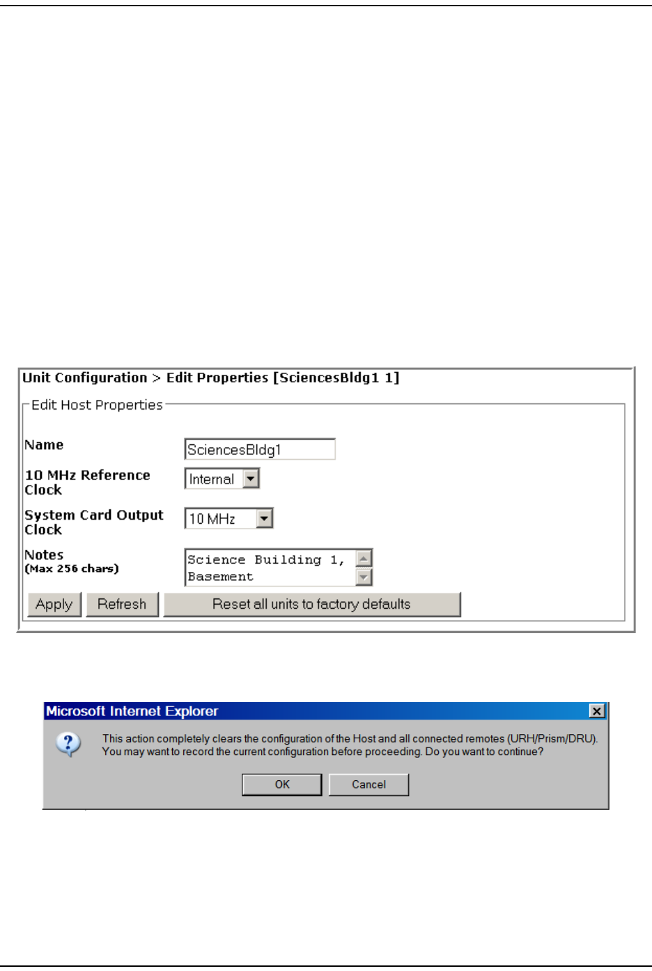
3I n t he Unit Menu bar, click Unit Configuration > Edit Properties, t o open t he Unit
Configuration > Edit Properties page.
4Click Reset all units to factory defaults.
5I n t he confirm at ion dialog, click OK.
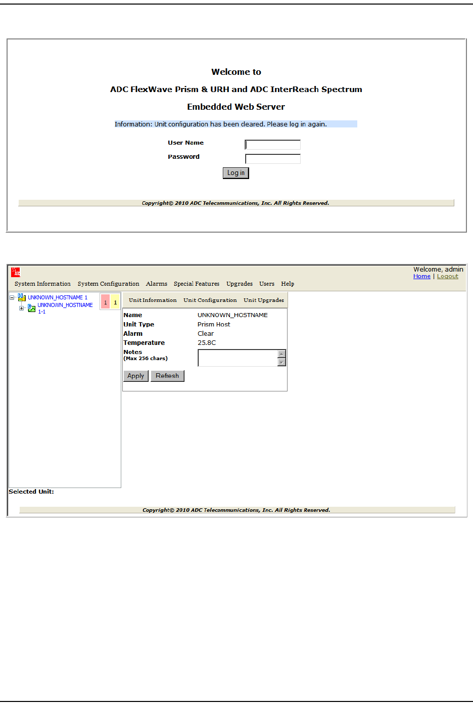
The syst em configuration is cleared, and you are logged out of your current
EMS session.
Syst em Managem ent
FlexWave Prism Elem ent Managem ent Syst em 7.1 User Manual Page 125
ADCP- 77- 177 • I ssue 1 • July 2011 © 2011 ADC Telecom m unicat ions, I nc.
6Log back int o the EMS t o reconfigure t he system .
NOTE: It may take a few minutes for the EMS to recognize the Host and connected remotes.
Backing Up a System Configurat ion
Page 126 FlexWave Prism Elem ent Managem ent System 7.1 User Manual
© 2011 ADC Telecommunications, Inc ADCP-77- 177 • I ssue 1 • July 2011
BACKING UP A SYSTEM CONFIGURATION
The Backup page allows you t o backup t he syst em configurat ion. A backup file size
is t ypically less t han 1 MB, and a new backup overwrit es the pre- exist ing backup.
You use the backup file t o restore t he configuration as described in “ Rest oring a
Backed Up Syst em Configurat ion” on page 128.
Do t he following t o backup a syst em configurat ion:
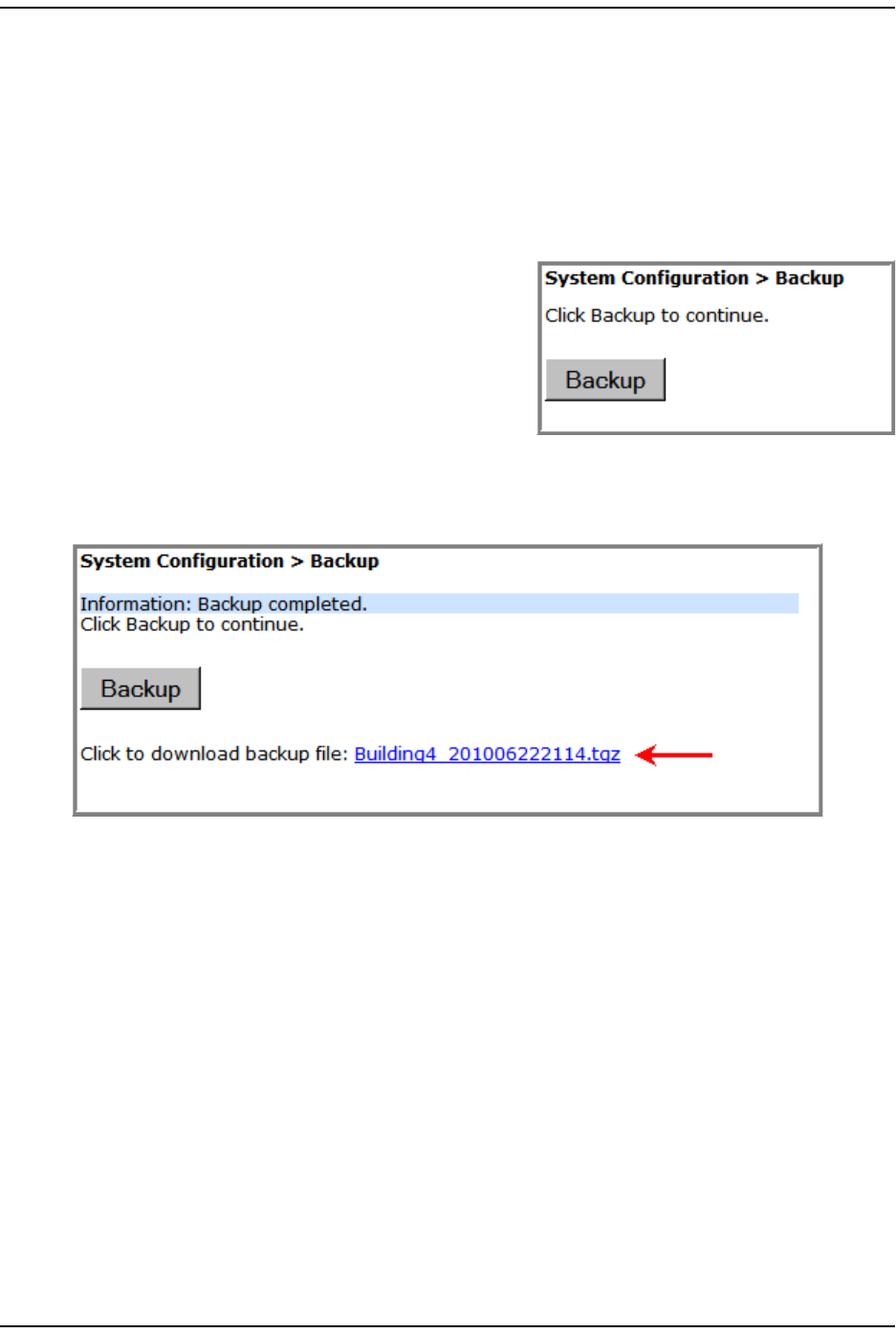
1I n t he Syst em Menu bar, click System
Configuration > Backup.
2Click Backup. I f the back up procedure fails,
the following error m essage displays:
Failed to create Back Up. At the end of a
successful backup, a link t o t he
downloaded file appears.
3To download the back-up file, click t he link
that appears, t he nam e for which is in the form at of HOSTNAME_<DATETIME>.tgz.
Only one file will be available.
Syst em Managem ent
FlexWave Prism Elem ent Managem ent Syst em 7.1 User Manual Page 127
ADCP- 77- 177 • I ssue 1 • July 2011 © 2011 ADC Telecom m unicat ions, I nc.
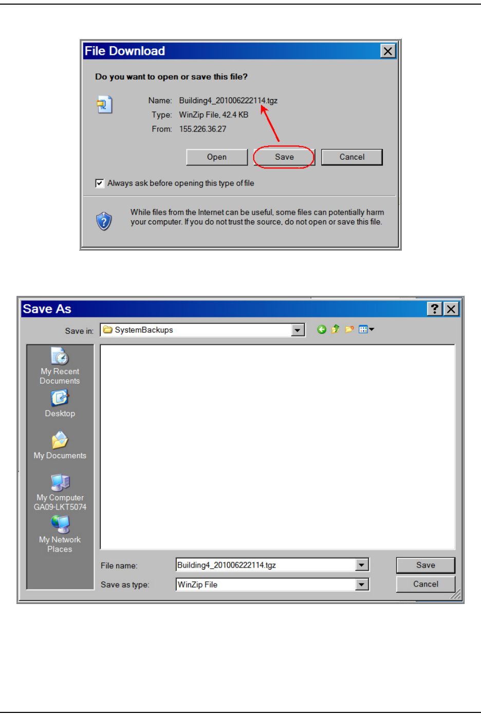
4I n t he File Download window, click Save.
5I n t he Save As window, navigat e to where you want t he backup file saved, and
then click Save.
Rest oring a Backed Up System Configur at ion
Page 128 FlexWave Prism Elem ent Managem ent System 7.1 User Manual
© 2011 ADC Telecommunications, Inc ADCP-77- 177 • I ssue 1 • July 2011
RESTORING A BACKED UP SYSTEM CONFIGURATION
CAUTION! A System Restore can only occur if a previous system configuration has been backed up as
described in “Backing Up a System Configuration” on page 126.
CAUTION! A system restore requires that you log back into the system. Once you click the Restore button, the
system will be unavailable for approximately two minutes. Perform this procedure during a
maintenance window.
NOTE: A System Restore can only be performed by a user logged in as admin user or by a user with
Network Manager rights. A user assigned only Network User rights will not see the System Restore
node in the Function System Tree.
The System Restore page allows for a restorat ion of a backed up syst em configurat ion,
as follows:
•The Restore funct ion assum es t hat the sam e or com parable replacem ent
hardware com ponents are in place as when t he Backup funct ion occurred. I f
hardware com ponent changes have occurred, alarm s t hat point to t he
differences will arise.
•I f a Rem ot e has been added ( that is, was not part of t he original system
hardware setup) , then t he newly added Rem ot e will not be restored since it was
not present during t he syst em configurat ion backup.
Do t he follow ing t o r est ore a sy st e m back up:
1Make sure t here is sufficient disk space for the backed up syst em configuration
that you want t o rest ore.
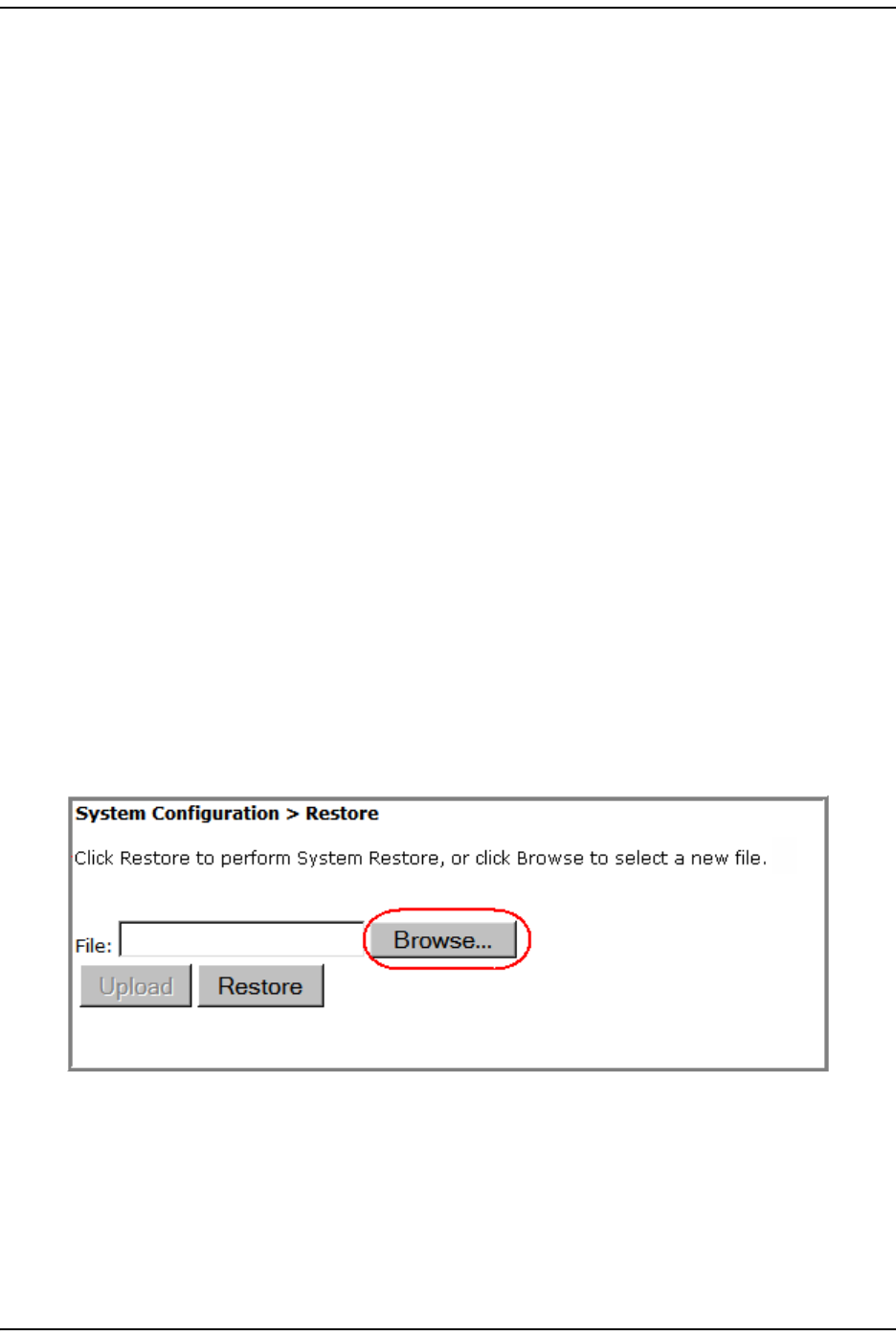
2I n the Syst em Menu bar, click System Configuration > Restore.
3Click t he Browse but t on next to t he File box t o browse to the location of t he
backup file.
Syst em Managem ent
FlexWave Prism Elem ent Managem ent Syst em 7.1 User Manual Page 129
ADCP- 77- 177 • I ssue 1 • July 2011 © 2011 ADC Telecom m unicat ions, I nc.
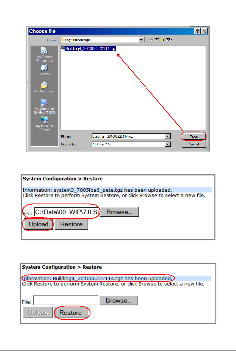
4I n t he Choose File window, click on t he back- up file to select it (the backup
filenam e is in the form at of HOSTNAME_<DATETIME>.tgz, and then click Open.
5I n t he Restore page, wait for t he file nam e and pat h t o display in t he File box and
for t he ennoblem ent of t he Upload but ton, and then click Upload.
6I n t he Restore page, wait for t he file upload m essage t o display and for the
ennoblem ent of the Upload and Restore buttons, and t hen click Restore.

Rest oring a Backed Up System Configur at ion
Page 130 FlexWave Prism Elem ent Managem ent System 7.1 User Manual
© 2011 ADC Telecommunications, Inc ADCP-77- 177 • I ssue 1 • July 2011
7I n t he confirm at ion dialog, click OK.
St atus m essages display t o not ify you if t he restorat ion failed or com plet ed
successfully.
Aft er a successful rest orat ion, you are logged out of t he syst em .
8Log back in t o t he EMS to cont inue m anagem ent activit ies.
Syst em Managem ent
FlexWave Prism Elem ent Managem ent Syst em 7.1 User Manual Page 131
ADCP- 77- 177 • I ssue 1 • July 2011 © 2011 ADC Telecom m unicat ions, I nc.
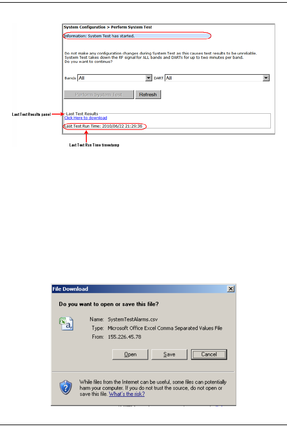
PERFORM SYSTEM TEST
Syst em Test perform s an RF integrit y check of the syst em . Cert ain alarm s ( such
as the RAU Antenna Disconnect alarm ) can only be set or cleared by running Syst em
Test .
CAUTION! Running System Test (System Configuration > Perform System Test) with un-terminated Host
DARTs may cause a false RLM Upconvert Fault. Ensure that all Host DARTs are terminated before
running System Test.
CAUTION! System Test interrupts RF transmission; System Test should therefore only be run during a normal
maintenance window.
CAUTION! Do not make any software or hardware configuration changes during System Test, as changes
made during the test will make the test results unreliable.
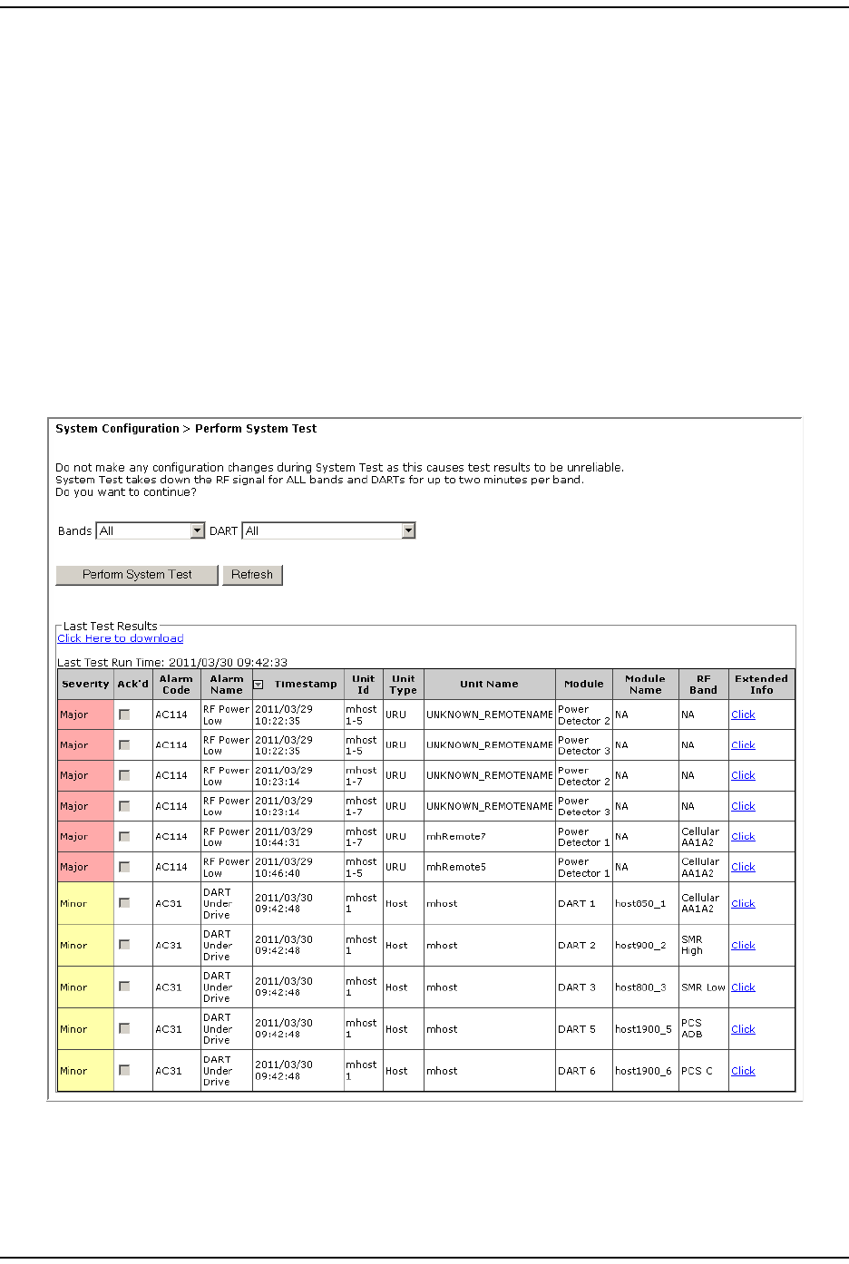
1I n the Syst em Menu bar, click System Configuration > Perform System Test.
NOTE: The table at the bottom of the Perform System Test page presents the results of the last
System Test, if any, as shown above.
Perform Syst em Test
Page 132 FlexWave Prism Elem ent Managem ent System 7.1 User Manual
© 2011 ADC Telecommunications, Inc ADCP-77- 177 • I ssue 1 • July 2011
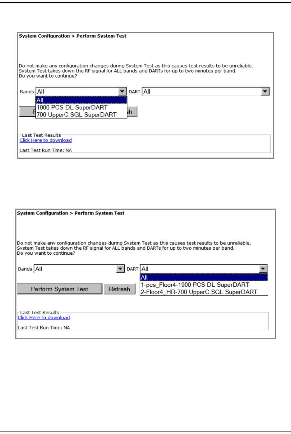
2I n t he Bands list , select t he passbands for which you want t o perform Syst em
Test . Only configured passbands will be list ed in t he Bands list .
3I n t he DART list , select t he DART you want t o perform Syst em Test. Only t hose
DARTS that are available will be list ed in t he DART list .
CAUTION! Regardless if only 1 DART or all DARTs are selected for System Test, System Test temporarily
shuts down the RF to all DARTs in the system.
Syst em Managem ent
FlexWave Prism Elem ent Managem ent Syst em 7.1 User Manual Page 133
ADCP- 77- 177 • I ssue 1 • July 2011 © 2011 ADC Telecom m unicat ions, I nc.
4Click Perform System Test. A System Test has started m essage displays.
This m essage should be followed by one of t hese m essages. You m ay need to
click Refresh to see these m essages.
•System Test passed.
•System Test failed.
•System Test not available.
•System Test passed – exceptions noted in log file.
Aft er a few seconds, t he Last Test Results panel updates wit h a list of m aj or and
m inor alarm s wit h a corresponding t im est am p for when System Test was run.
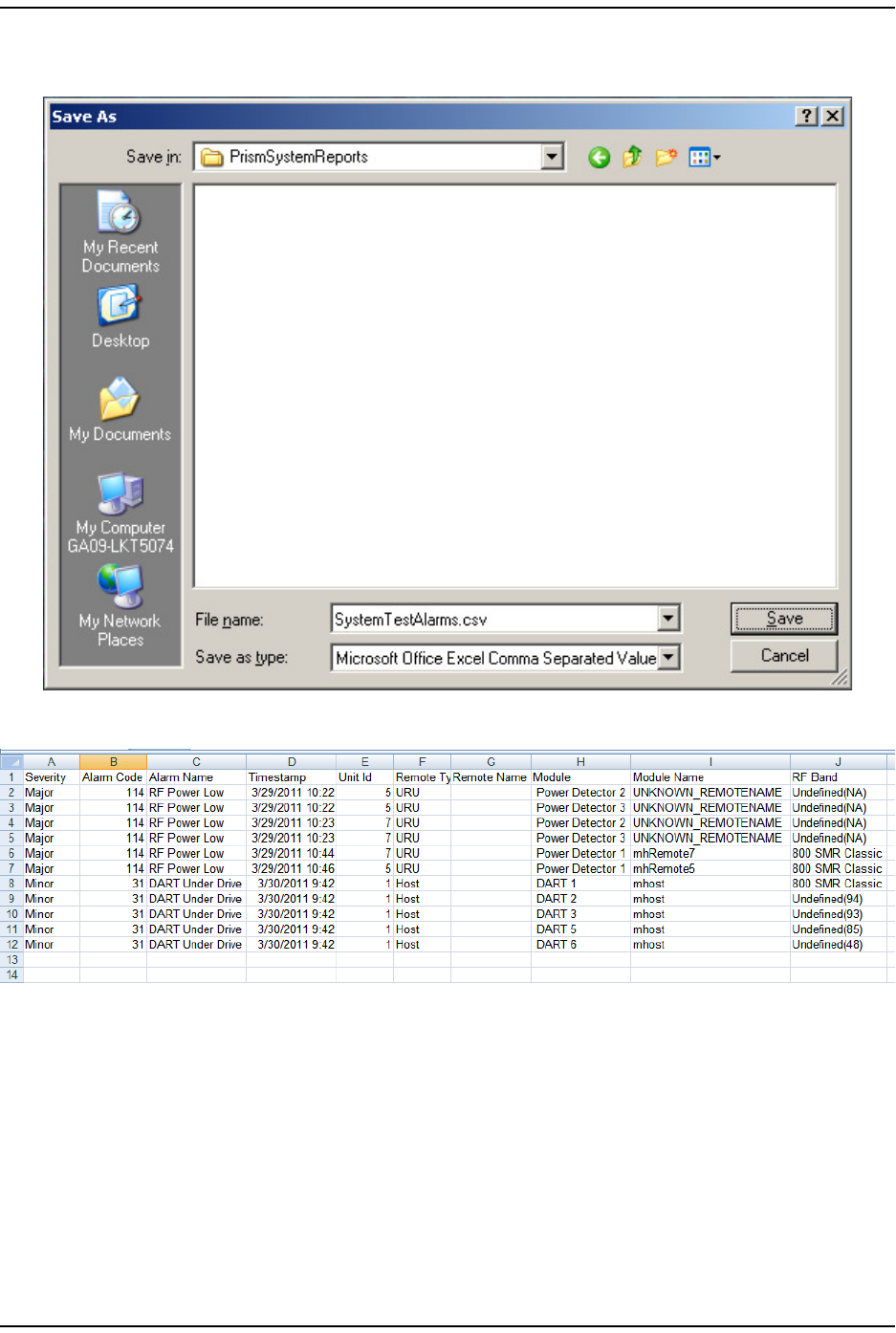
5( Opt ional) Do the following t o download t he result s of System Test (to m ake
the file available for later use, such as t roubleshoot ing) .
aClick t he Click Here to Download link.
bI n t he File Download dialog, click Save.
Perform Syst em Test
Page 134 FlexWave Prism Elem ent Managem ent System 7.1 User Manual
© 2011 ADC Telecommunications, Inc ADCP-77- 177 • I ssue 1 • July 2011
cI n t he Save As dialog, navigat e t o where you want to save t he file, and t hen
click Save.
The file is saved in Excel form at .
Syst em Managem ent
FlexWave Prism Elem ent Managem ent Syst em 7.1 User Manual Page 135
ADCP- 77- 177 • I ssue 1 • July 2011 © 2011 ADC Telecom m unicat ions, I nc.
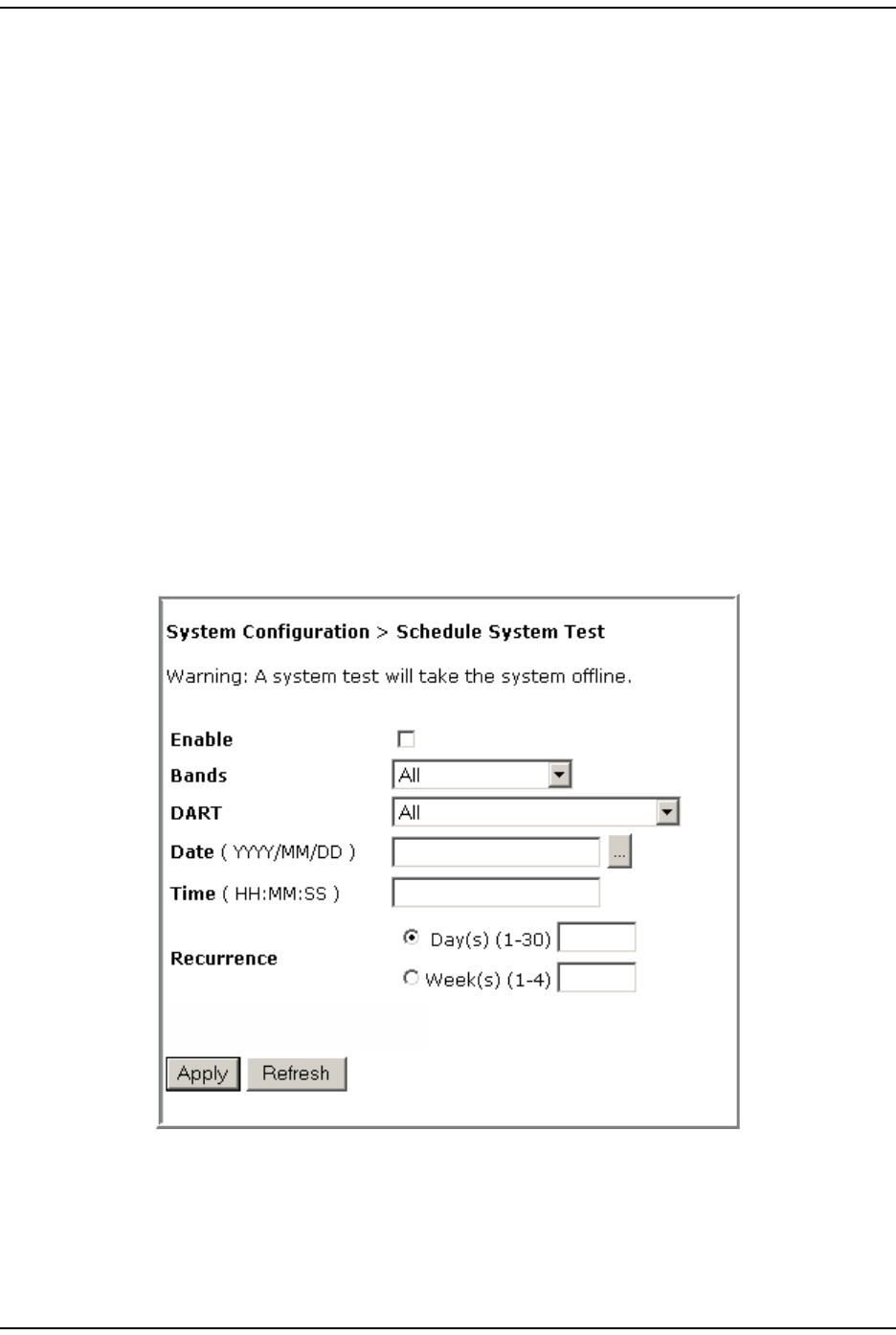
SCHEDULE SYSTEM TEST
You can schedule a Syst em Test t o run on a specific dat e and tim e, as described in:
•“ Schedule Syst em Test s by Dat e and Tim e” on page 135
•“ Disable a Scheduled System Test ” on page 137
Schedule System Tests by Date and Time
CAUTION! Running System Test (System Configuration > Perform System Test) with un-terminated Host
DARTs may cause a false RLM Upconvert Fault. Ensure that all Host DARTs are terminated before
running System Test.
CAUTION! System Test interrupts RF transmission; System Test should therefore only be run during a normal
maintenance window.
CAUTION! Do not make any software or hardware configuration changes during System Test, as changes
made during the test will make the test results unreliable.
Do t he following t o schedule a single or recurring Syst em Test:
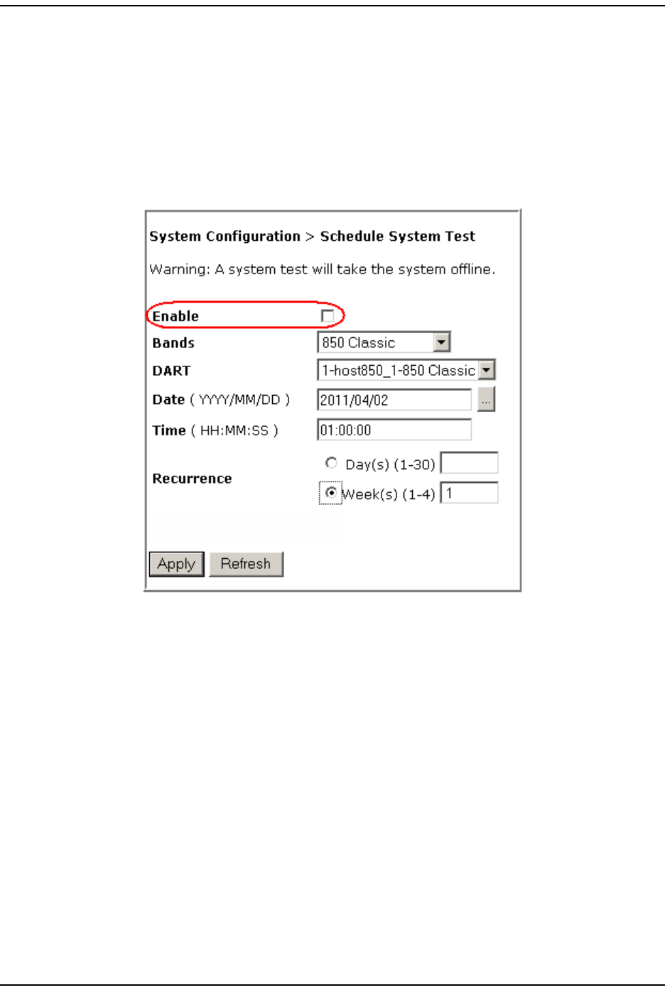
1I n the Syst em Menu bar, click System Configuration > Schedule System Test.
2Select Enable t o enable the scheduled Syst em Test ( see also “ Disable a
Scheduled System Test ” on page 137) .
3I n t he Bands list , select t he band( s) that you want t o test .
4I n t he DART list , select t he DART(s) t hat you want t o t est .
Schedule Syst em Test
Page 136 FlexWave Prism Elem ent Managem ent System 7.1 User Manual
© 2011 ADC Telecommunications, Inc ADCP-77- 177 • I ssue 1 • July 2011
5Click t he icon to t he right of t he DATE box to schedule on which dat e t he Syst em
Test will run. I f you enter t he date m anually, use the YYYY/MM/DD form at . For
exam ple, to run a Syst em Test on 14 June 2011, enter: 2011/06/14.
6I n t he Time box, ent er the tim e that the Syst em Test is to run. Use the 24- hour
tim eclock form at of HH:MM:SS.
7( Opt ional) Use the Recurrence radio but t ons to set up a recurring Syst em Test .
•To have the Syst em Test recurrence int erval be counted by days, select the
Day(s) (1-30) radio but t on, and t hen in the corresponding box, ent er how
m any days should pass between each occurrence of this Syst em Test .
•To have t he Syst em Test recurrence int erval be counted by weeks, select
the Week(s) (1-4) radio but t on, and t hen in t he corresponding box, ent er how
m any weeks should pass bet ween each occurrence of this Syst em Test .
8Click Apply.
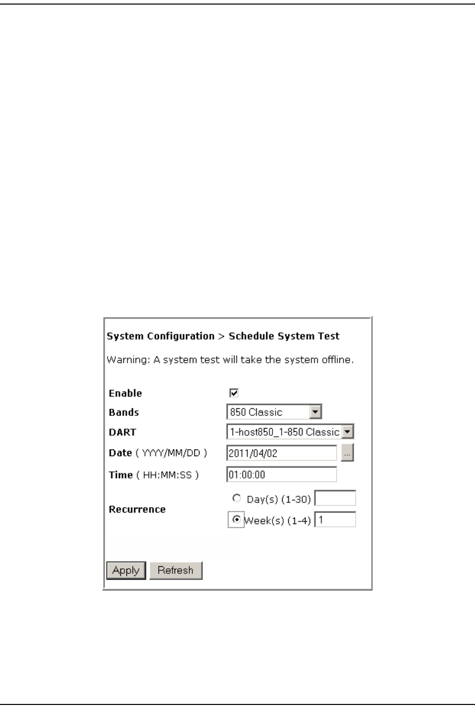
NOTE: If you leave either the DATE or TIME parameter empty and then click Apply, Schedule System Test
will not run. However, if you leave both the DATE and TIME parameters empty and then click Apply,
the System Test starts immediately.
The following exam ple has scheduled a Syst em Test for 850 Classic passbands
on 850 Classic DARTs inst alled in Host1 t o occur on 2 April 2011 at 1: 00 AM.
This System Test will occur in one- week int ervals.
Syst em Managem ent
FlexWave Prism Elem ent Managem ent Syst em 7.1 User Manual Page 137
ADCP- 77- 177 • I ssue 1 • July 2011 © 2011 ADC Telecom m unicat ions, I nc.
Disable a Scheduled System Test
When you disable a scheduled Syst em Test, t he Bands, DART, Date, and Time set ting
rem ain, but the test will not be run again unt il enabled.
1I n the Syst em Menu bar, click System Configuration > Schedule System Test.
2Deselect Enable.
3Click Apply.
Set SNMP Trap Managers
Page 138 FlexWave Prism Elem ent Managem ent System 7.1 User Manual
© 2011 ADC Telecommunications, Inc ADCP-77- 177 • I ssue 1 • July 2011
SET SNMP TRAP MANAGERS
The Set SNMP Trap Managers page allows you t o add, delet e, and m odify SNMP Trap
Managers.
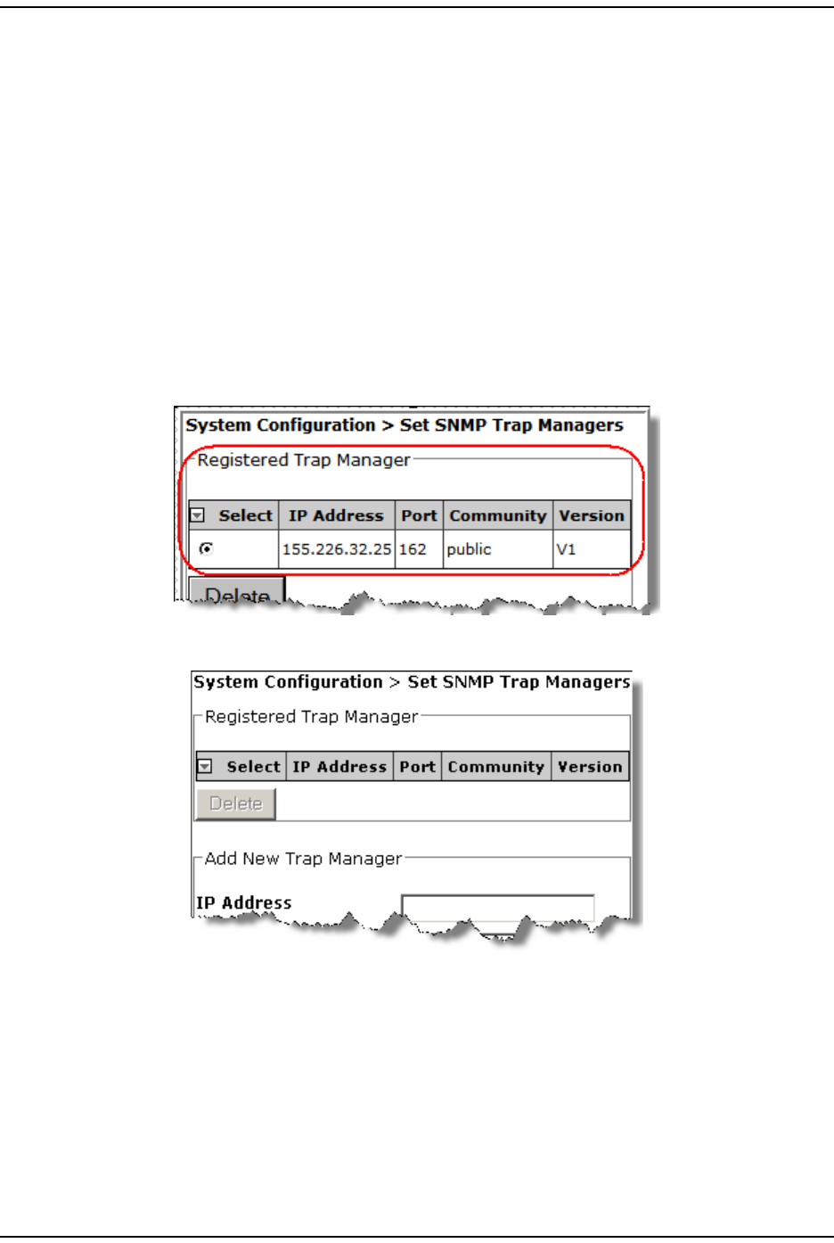
The Registered Trap Manager table, at the top of the page, details any exist ing SNMP
Trap Managers, where:
•Select radio but t on—allows you t o select an exist ing SNMP Trap Manager to
m odify or delet e it .
•IP Address—shows t he I P address of regist ered trap m anagers
•Port—shows the port num ber for regist ered t rap m anagers
•Community—shows t he Com m unity password for regist ered trap m anagers
•Version—shows t he trap version for regist ered t rap m anagers
I f a Trap Manager has not been created, t he t able is em pt y:
Syst em Managem ent
FlexWave Prism Elem ent Managem ent Syst em 7.1 User Manual Page 139
ADCP- 77- 177 • I ssue 1 • July 2011 © 2011 ADC Telecom m unicat ions, I nc.
Adding an SNMP Trap Manager
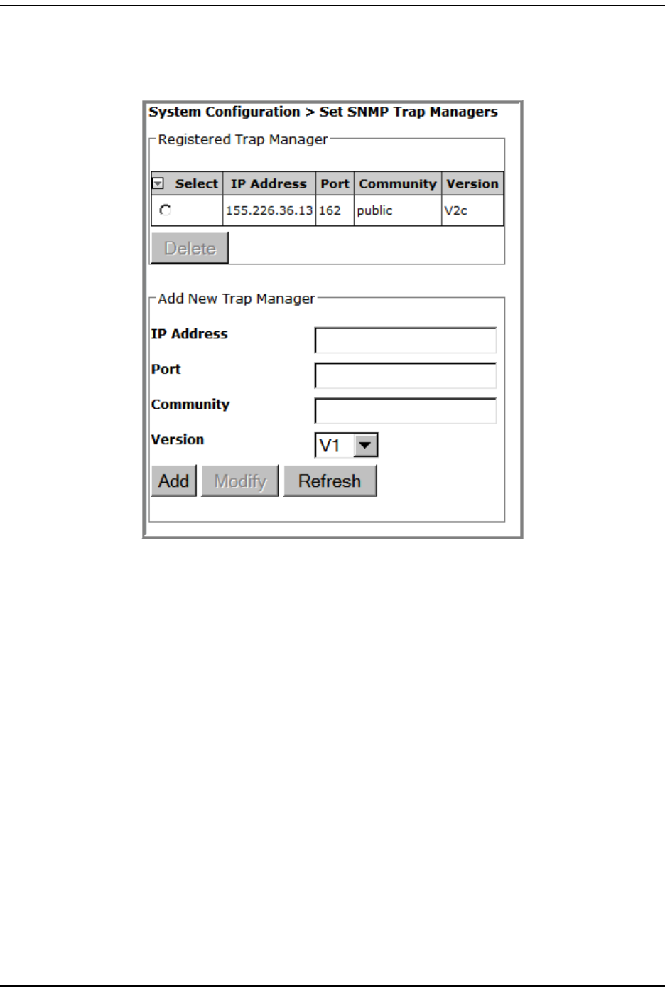
1I n the Syst em Menu bar, click System Configuration > Set SNMP Trap Managers.
2I n t he Add New Trap Manager panel, do t he following:
aI n t he IP Address box ent er the I P address of t he device t hat you want t o add
as a t rap receiver. The address m ust be in t he xxx.xxx.xxx.xxx form at.
bI n t he Port box, ent er t he port on the device t hat will receive the traps. The
norm al and recom m ended SNMP Trap port is 162.
cI n t he Community box, enter a password that will allow access t o the device.
The Community password m ust be between 6 and 20 alphanum eric characters
( usually public or private) .
dI n t he Version list , select the trap version for the SNMP Trap Manager t hat
you are regist ering ( V1 or V2c) .
Set SNMP Trap Managers
Page 140 FlexWave Prism Elem ent Managem ent System 7.1 User Manual
© 2011 ADC Telecommunications, Inc ADCP-77- 177 • I ssue 1 • July 2011
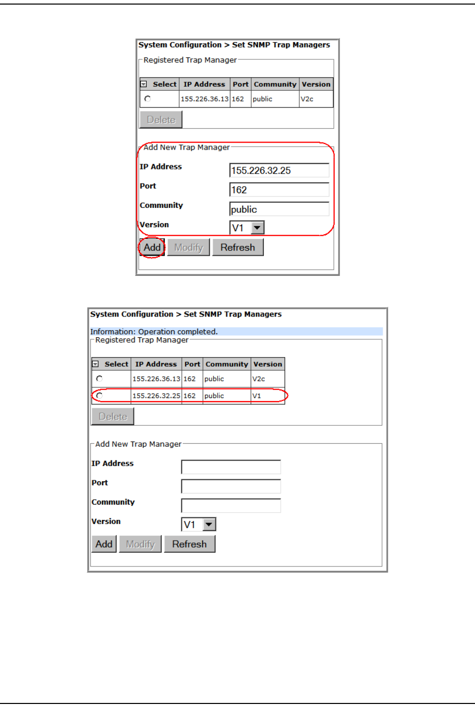
3Click Add.
The Registered Trap Managers table updat es wit h the new SNMP Trap Manager.
Syst em Managem ent
FlexWave Prism Elem ent Managem ent Syst em 7.1 User Manual Page 141
ADCP- 77- 177 • I ssue 1 • July 2011 © 2011 ADC Telecom m unicat ions, I nc.
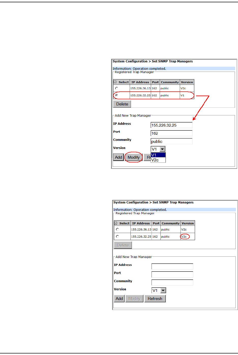
Modifying an SNMP Trap Manager
1I n t he Syst em Menu bar, click System Configuration > Set SNMP Trap Managers. The
Registered Trap Managers table list s exist ing SNMP Trap Managers.
2I n t he Registered Trap Managers t able, select t he trap m anager t hat you want t o
m odify.
3I n t he Add New Trap Manager
panel, do any of t he following:
•I n t he IP Address box ent er a
new I P address. The
address m ust be in t he
xxx.xxx.xxx.xxx form at.
•I n t he Port box, enter t he
port on t he device t hat will
receive t he traps. The
norm al and recom m ended
SNMP t rap port is 162.
•I n t he Community box, enter
a password t hat allows
access to t he device
( usually public or privat e) .
The Com m unit y password
is lim it ed to 20 charact ers.
•I n t he Version list , select the trap version for the SNMP Trap Manager t hat
you are regist ering.
4Click Modify.
The Registered Trap Managers t able
updat es wit h t he m odified
SNMP Trap Manager.
Set SNMP Trap Managers
Page 142 FlexWave Prism Elem ent Managem ent System 7.1 User Manual
© 2011 ADC Telecommunications, Inc ADCP-77- 177 • I ssue 1 • July 2011
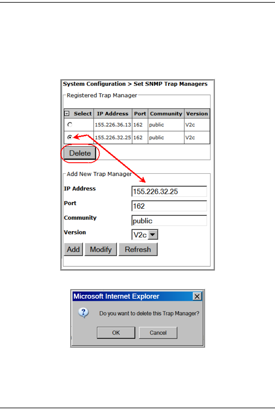
Deleting an SNMP Trap Manager
1I n t he Syst em Menu bar, click System Configuration > Set SNMP Trap Managers. The
Registered Trap Managers table list s exist ing SNMP Trap Managers.
2I n t he Registered Trap Managers t able, select the trap m anager that you want t o
delet e.
3Click Delete.
4I n t he confirm at ion window, click OK.
Syst em Managem ent
FlexWave Prism Elem ent Managem ent Syst em 7.1 User Manual Page 143
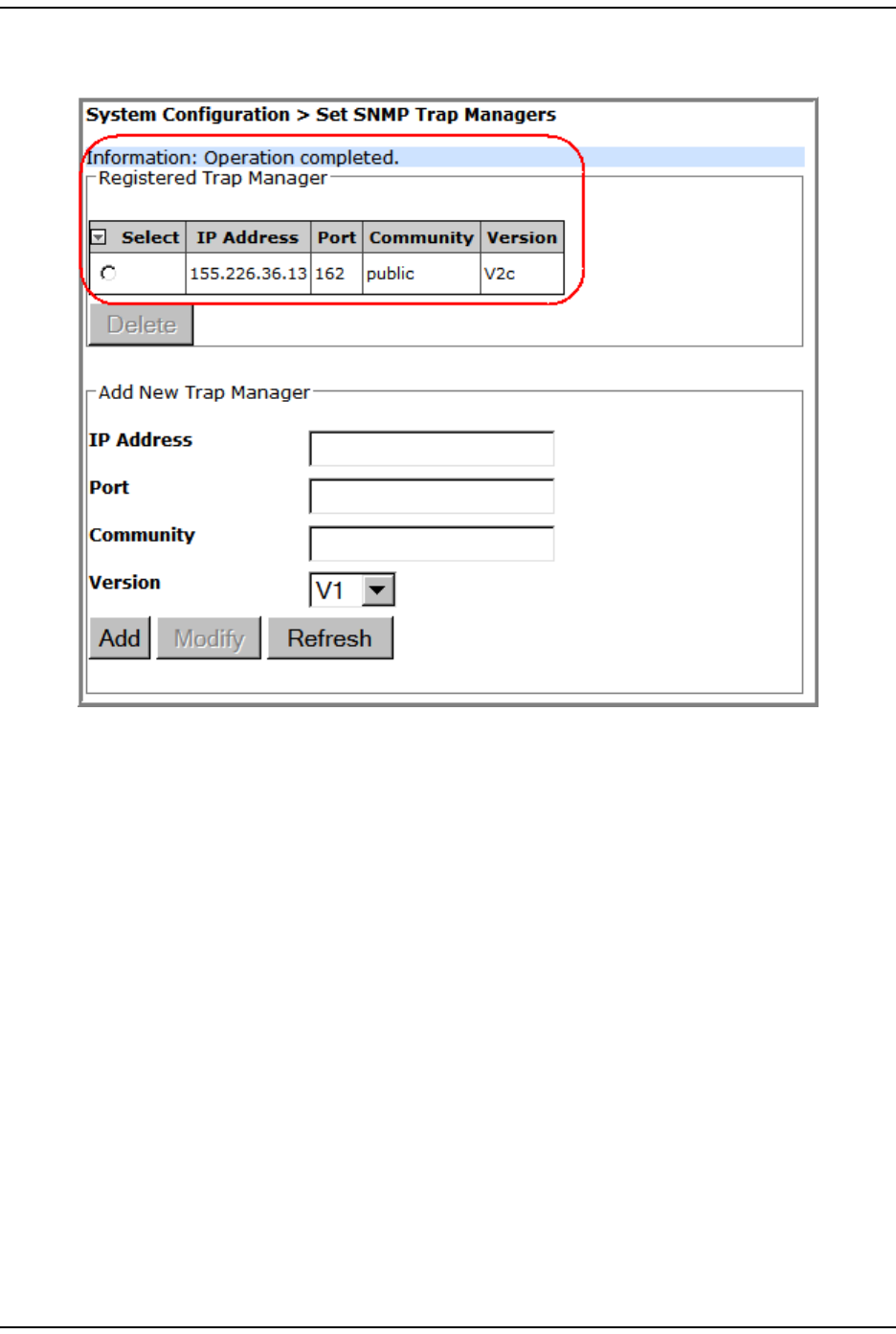
ADCP- 77- 177 • I ssue 1 • July 2011 © 2011 ADC Telecom m unicat ions, I nc.
The delet ed SNMP Trap Manager is rem oved from t he Registered Trap Managers
table and will no longer receive traps.
Set up SNMP
Page 144 FlexWave Prism Elem ent Managem ent System 7.1 User Manual
© 2011 ADC Telecommunications, Inc ADCP-77- 177 • I ssue 1 • July 2011
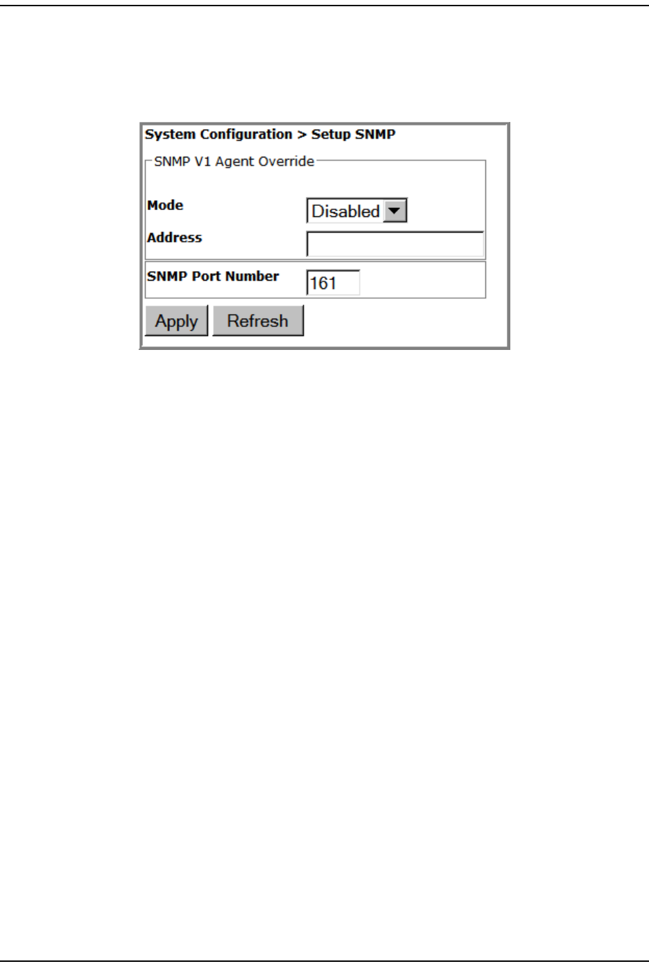
SETUP SNMP
1To access t he Setup SNMP page, in t he Syst em Menu bar, click System Configuration
> Setup SNMP.
2I n t he SNMP V1 Agent Override panel, do the following.
aI n t he Mode list , select t he SNMP V1 Agent Override m ode:
• Enabled
• Disabled
bI n t he Address box, ent er the SNMP V1 Agent Override address. I f t he SNMP
Agent Override Mode is not Disabled, t he syst em uses this address as t he
source address in t he t raps.
3I n t he SNMP Port Number box, ent er the SNMP port num ber for sets and gets.
4Click Apply to m odify the SNMP set t ings.
Syst em Managem ent
FlexWave Prism Elem ent Managem ent Syst em 7.1 User Manual Page 145
ADCP- 77- 177 • I ssue 1 • July 2011 © 2011 ADC Telecom m unicat ions, I nc.
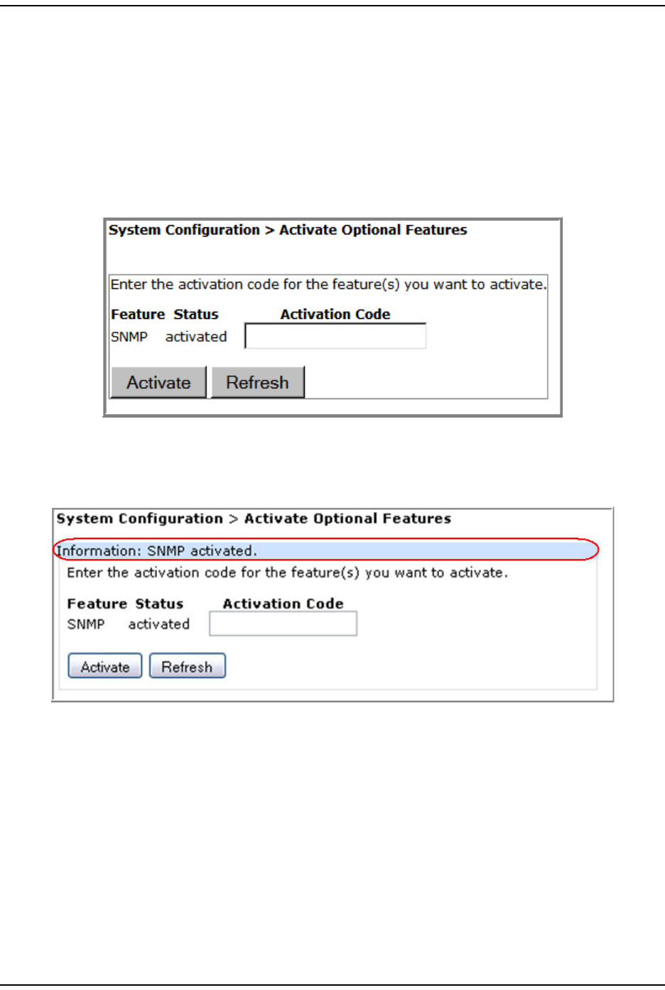
ACTIVATE OPTIONAL FEATURES
The Activate Optional Features page allows you t o act ivat e opt ional features available
in t he system t hat are purchased aft er t he Host Unit has been shipped.
NOTE: Activation Codes are supplied by ADC Technical Assistance (see “Appendix C: Contacting ADC/TE
Connectivity” on page 297).
1To access the Activate Optional Features page, in t he Syst em Menu bar, click System
Configuration > Activate Optional Features.
2I n t he Activation Code box that corresponds to t he feat ure t hat you want to
act ivat e, ent er t he act ivat ion code provided by ADC.
3Click Activate. The following Information m essage displays.

Activat e Opt ional Features
Page 146 FlexWave Prism Elem ent Managem ent System 7.1 User Manual
© 2011 ADC Telecommunications, Inc ADCP-77- 177 • I ssue 1 • July 2011
I nt ent ionally Blank Page

FlexWave Prism Elem ent Managem ent Syst em 7.1 User Manual Page 147
ADCP- 77- 177 • I ssue 1 • July 2011 © 2011 ADC Telecommunications, Inc.
MANAGING UNITS
Basic Unit Views .................................................................................................................. 148
View Optical Port s ................................................................................................................ 149
Viewing DARTs .................................................................................................................... 151
Viewing Net work St atist ics .................................................................................................... 152
Editing Unit Properties .......................................................................................................... 153
Configuring Opt ical Ports.......................................................................................................153
Viewing the Status of t he Host Unit ........................................................................................ 154
Viewing t he St at us of a Rem ot e Unit ....................................................................................... 156
Module St atus Table ....................................................................................................... 156
DART St atus Table .................................................................................................... 157
LNA St atus Table ...................................................................................................... 158
LPA St at us Table....................................................................................................... 158
PD Stat us Table ........................................................................................................ 159
Opt ical Status Table ........................................................................................................ 159
Rem ot e Stat us Table....................................................................................................... 160
Rem ot e Unit Capacity and Tem perat ure............................................................................. 160
Clear ing DART Configurat ions ................................................................................................ 161
Set t he Capacit y for a New Rem ot e Unit RSI Board ................................................................... 162
Using t he EMS GUI to Change t he Rem ot e Unit Capacit y ...................................................... 162
Using Telnet or ssh to Change t he Rem ot e Unit Capacit y...................................................... 163
Rebooting a Unit .................................................................................................................. 164
Resett ing an LPA.................................................................................................................. 165
This sect ion describes the Prism EMS param eters whose set tings affect t he
individual unit s wit hin a Prism syst em .
Topics Page
Basic Unit View s
Page 148 FlexWave Prism Elem ent Managem ent System 7.1 User Manual
© 2011 ADC Telecommunications, Inc ADCP-77- 177 • I ssue 1 • July 2011
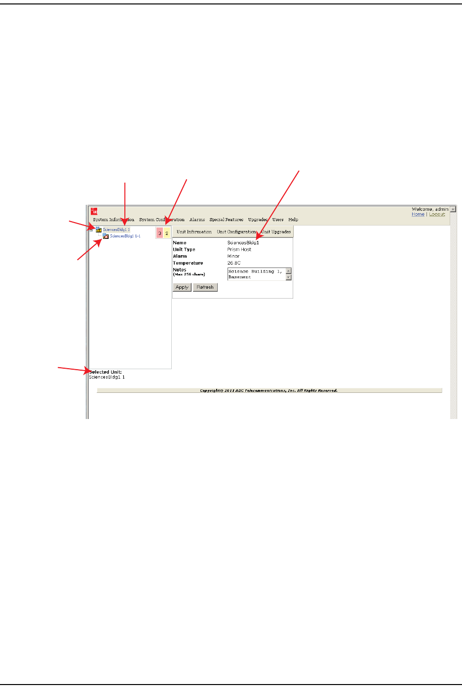
BASIC UNIT VIEWS
When you click on a device icon in t he Syst em Tree, t he following view opens in
the EMS View Fram e, in which t here are three places where t he select ed device is
ident ified. Not ice also the indicat ors for act ive alarm s. I n this inst ance the alarm
overlays on the Host and Rem ot e Unit icons indicat e that an alarm is act ive on
each device, and t he Alarm Count er shows the count of act ive alarm s.
The following graphic identifies the com ponents in a basic unit view.
Figure 22. Overview of Components in a Basic Unit View
The Unit view provides t he following inform ation:
•Name—user- defined or system nam e of the select ed unit .
•Unit Type—t he type of device that t he select ed unit is:
–Host
–PRU—Prism Rem ot e Unit
–URU—URH Rem ote Unit
•Alarm—highest level of alarm occurring on the select ed unit . Not ice t hat in t his
exam ple, t he Alarm indicat ors show t hat t here are four Minor alarm s act ive on
this syst em . The Unit view let s you know that at least one of t he alarm s is
act ive on the Host .
•Temperature—int ernal tem perat ure of t he selected unit.
•Notes—text box t hat allows you t o ent er notes specific t o the select ed unit . You
can enter up to 256 charact ers; all keyboard characters can be used.
Host icon with
Minor alarm overlay
Remote Unit icon with
Major alarm overlay
Unit identifier
(by Unit Name)
Unit identifiers in
System Tree
(by Unit Name and Unit ID)
Alarm Counter
(system wide)
Unit identifier
(by Unit Name)
Managing Unit s
FlexWave Prism Elem ent Managem ent Syst em 7.1 User Manual Page 149
ADCP- 77- 177 • I ssue 1 • July 2011 © 2011 ADC Telecom m unicat ions, I nc.
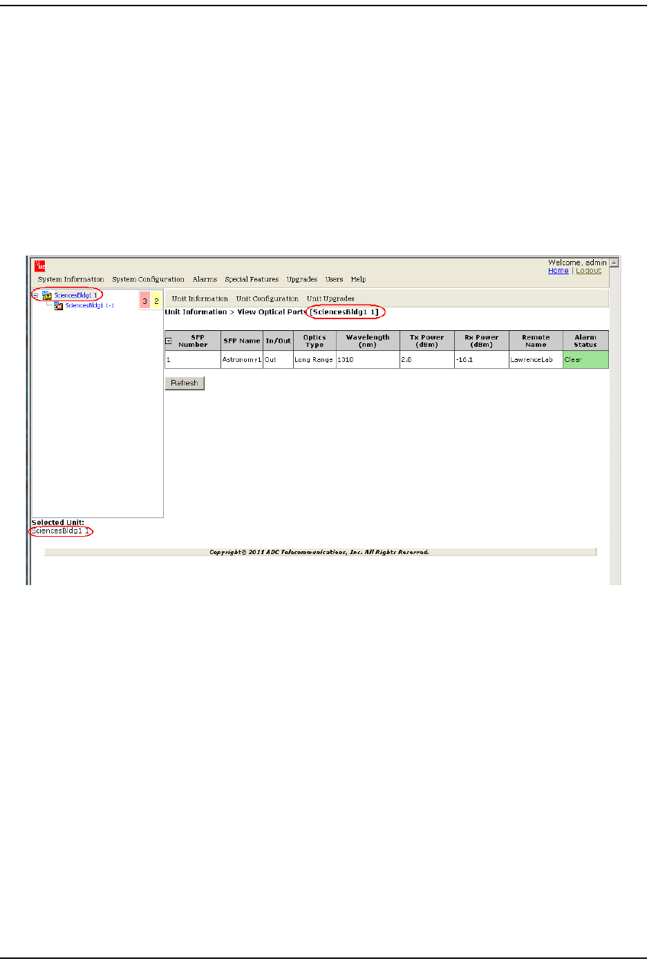
VIEW OPTICAL PORTS
The View Optical Ports page shows the current usage and alarm st at us of the optical
port s on a Host or a PRU/ URU plus the current values of key operat ing param et ers.
The Host and PRU/ URU chassis have eight opt ical ports, but the View Optical Ports
page only shows act ive port s ( t hose physically connect ed t o a Host or PRU/ URU) .
Each port in t he page represent s one set of forward and reverse pat hs bet ween a
Host and Rem ot e.
1I n t he Syst em Tree, click on an icon for a Host or Rem ot e Unit.
2I n the Unit Menu bar, click Unit Information > View Optical Ports.
The View Optical Ports table has the following com ponent s:
•SFP Number—Syst em assigned port num ber.
•SFP Name—user ent ered port nam e or UNKNOWN_SFPNAME, which indicat es that
no nam e has been ent ered.
•In/Out—used for cascading, which is not support ed in this release. The Host will
therefore always be set as Out ( indicat es that t he forward link for t he connect ed
SFP is going away from t he Host) and t he SFPs for all Rem ot e Unit s will always
be set as In.
• Optics Type
–LongRange—26 dB
–IntermediateRange—18 dB.

View Opt ical Port s
Page 150 FlexWave Prism Elem ent Managem ent System 7.1 User Manual
© 2011 ADC Telecommunications, Inc ADCP-77- 177 • I ssue 1 • July 2011
•Wavelength (nm)—wave length transm it t ed through t his port:
– Non- duplex and WDM configurat ions: 1550 nm fwd or 1310 nm rev
– CWDM configurations can be one of eight wavelengths:
•Tx Power (dBm)—launch power level in dBm of forward path signal. The m inim um
FWD launch power is - 2 dBm , and the m axim um is 3 dBm .
•Rx Power (dBm)—receive power level in dBm of reverse path signal, which
incorporates the launch power of t he Rem ote Unit SFP plus all optical losses
( insert ion losses, fiber cable loss, and so fort h) .
•Host Name/Remote Name—dependent on t he unit select ed in St ep 1 on page 149:
– I f a Host Unit was select ed, t hen t he colum n is labeled Remote Name and the
dat a in the colum n pert ains t o t he Rem ot e connected t o this Opt ical port
ident ified in SFP Number and SFP Name.
– I f a Rem ot e Unit was select ed, t hen the colum n is labeled Host Name and t he
dat a in t he colum n pert ains t o t he Host (for selected PRU/ URU) connect ed
to t his Opt ical port identified in SFP Number and SFP Name.
•Alarm Status—whet her an alarm is act ive. I f an alarm is act ive, t here will be a
Minor or Major link t hat you click t o open a dialog t hat defines t he act ive alarm ,
as described in “Viewing Alarm Det ails” on page 45. The background color of
the Alarm Status cell also indicat es t he alarm level ( see “ Alarm Color Codes” on
page 44) .
1470 nm 1510 nm 1550 nm 1590 nm
1490 nm 1530 nm 1570 nm 1610 nm
Managing Unit s
FlexWave Prism Elem ent Managem ent Syst em 7.1 User Manual Page 151
ADCP- 77- 177 • I ssue 1 • July 2011 © 2011 ADC Telecom m unicat ions, I nc.
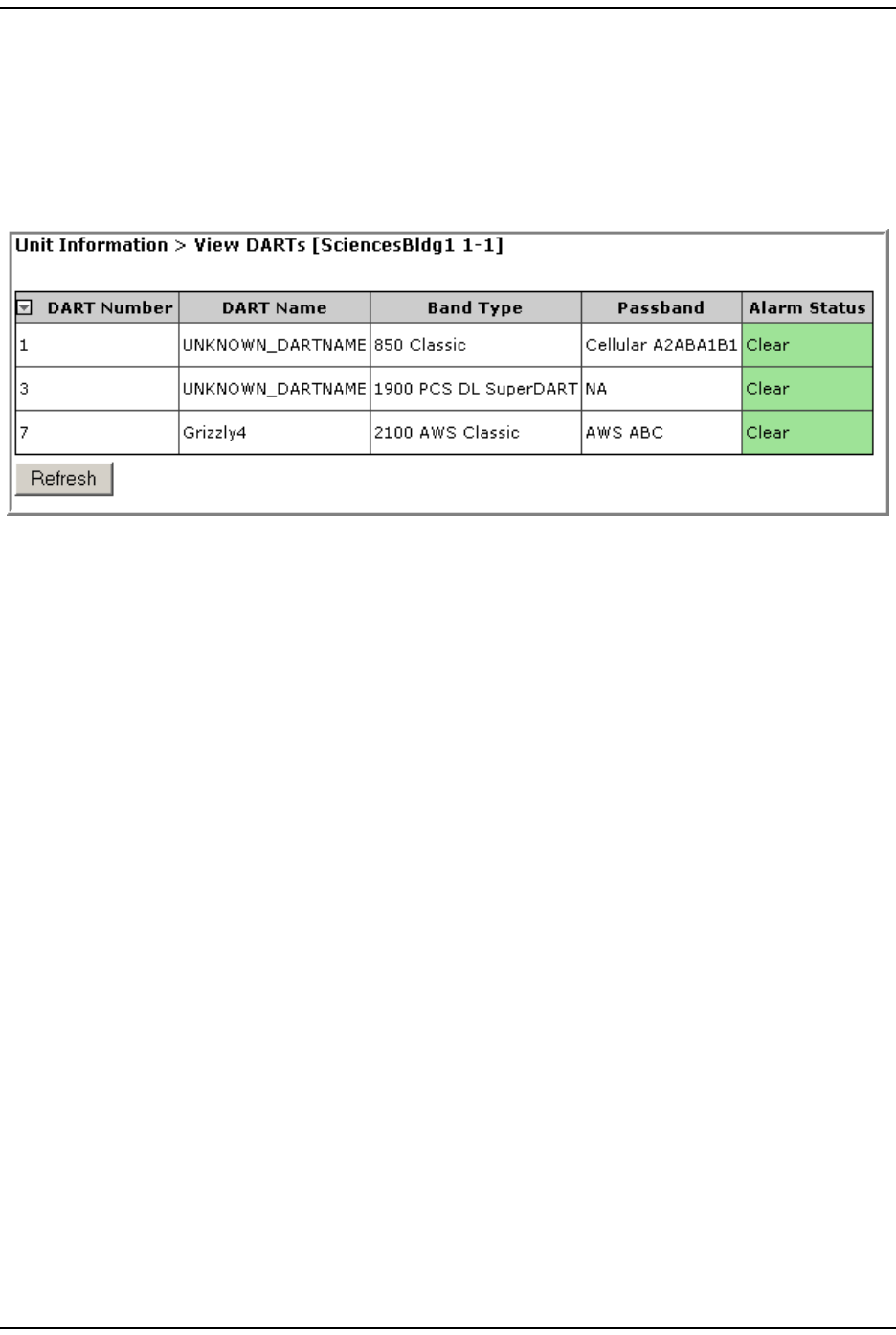
VIEWING DARTS
1I n t he Syst em Tree, click on t he icon of t he Host or PRU/ URU for which you
want t o view inform ation on it s DARTs.
2I n t he Unit Menu bar, click Unit Information > View DARTs t o open t he View DARTs
page.
The table in t he View DARTs page provides t he following inform ation:
•DART Number—identifies any installed DARTs by the slot num ber in which it is
inst alled in the Host or PRU/ URU chassis
•DART Name—syst em or user- assigned nam e; default is UNKNOWN_DARTNAME.
•Band Type—which DART m odel is installed, and t he band t ype that it is
providing
•Passband—t ype of passband
•Alarm Status—whet her an alarm is active. I f an alarm is act ive, t here will be
a Minor or Major link t hat you click t o open a dialog that defines t he act ive
alarm , as described in “ Viewing Alarm Details” on page 45. The background
color of t he Alarm Status cell also indicat es t he alarm level ( see “ Alarm Color
Codes” on page 44) .
View ing Network St at ist ics
Page 152 FlexWave Prism Elem ent Managem ent System 7.1 User Manual
© 2011 ADC Telecommunications, Inc ADCP-77- 177 • I ssue 1 • July 2011
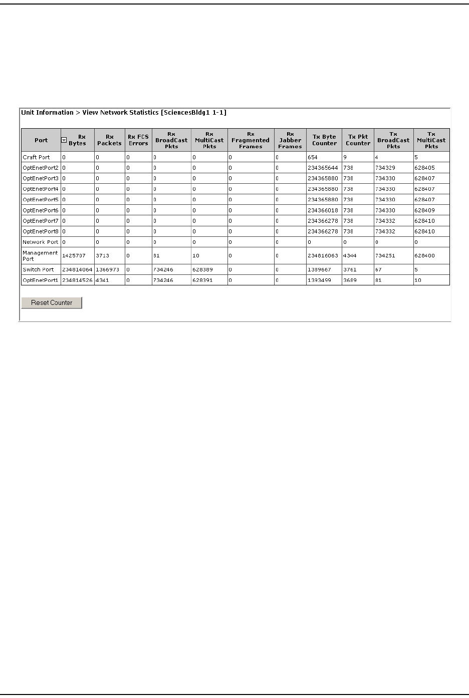
VIEWING NETWORK STATISTICS
1I n t he Syst em Tree, click on an icon for a Host or Rem ot e Unit .
2I n t he Unit Menu bar, click Unit Information > View Network Statistics t o open t he View
Network Statistics page.
The View Network Statistics table has the following com ponents:
•Port—I dent ifies t he port s in the net work.
•Rx Bytes—Receive byt e count er t hat increm ents by t he byt e count of fram es
received, including t hose in bad packet s, excluding pream ble and SFD but
including FCS bytes.
•Rx Packets—Receive packet count er that increm ent s for each fram e received
packet ( including bad packet s, all unicast , broadcast, and m ult icast packets) .
•RX FCS Errors—Receive FCS error count er that increm ents for each fram e
received that has an int egral 64 t o 1518 lengt h and contains a fram e check
sequence error.
•Rx Broadcast Pkts—Receive broadcast packet count er t hat increm ents for each
broadcast good fram e of lengt hs 64 to 1518 ( non VLAN) or 1522 ( VLAN) ,
excluding m ult icast fram es. Does not include range/ length errors.
•Rx Multicast Pkts—Receive m ult icast packet counter t hat increm ents for each
m ult icast good fram e of lengt hs 64 to 1518 ( non VLAN) or 1522 ( VLAN) ,
excluding broadcast fram es. This count does not include range/ lengt h errors.
•Rx Fragmented Frames—Receive fragm ent s counter t hat increm ent s for each fram e
received that cont ains an invalid FCS and is less than 64 byt es. This includes
int egral and non-int egral lengt hs.
•Rx Jabber Frames—Receive jabber count er t hat increm ents for fram es received
that exceed 1518 ( non VLAN) or 1522 ( VLAN) bytes and cont ain an invalid FCS.
This includes alignm ent errors.

Managing Unit s
FlexWave Prism Elem ent Managem ent Syst em 7.1 User Manual Page 153
ADCP- 77- 177 • I ssue 1 • July 2011 © 2011 ADC Telecom m unicat ions, I nc.
•Tx Byte Counter—Transm it byte count er t hat increm ents by t he num ber of byt es
that were put on t he wire including fragm ents of fram es t hat were involved
wit h collisions. This count does not include pream ble/ SFD or j am bytes. This
counter does not count if t he fram e is t runcat ed.
•Tx Pkt Counter—Transm it packet counter that increm ent s for each t ransm it t ed
packet ( including bad packets, excessive deferred packets, excessive collision
packets, lat e collision packet s, all unicast , broadcast, and m ult icast packet s).
•Tx Broadcast Pkts—Transm it broadcast packet counter t hat increm ent s for each
broadcast fram e t ransm it t ed ( excluding m ult icast fram es) .
•Tx Multicast Pkts—Transm it m ult icast packet count er that increm ents for each
m ult icast valid fram e transm it t ed ( excluding broadcast fram es) .
•Reset Counter but ton—click t o clear t he st at istics in the Network Statistics page.
EDITING UNIT PROPERTIES
Unit propert ies are set during init ial set up, but can be changed at any t im e. See
one of t he following:
•“ Configure Basic Host Unit Propert ies” on page 64
•“ Label t he PRU/ URU” on page 66.
CONFIGURING OPTICAL PORTS
Opt ical port configurations are set during init ial set up, but can be changed at any
tim e. See one of t he following:
•See “ Label the Host Opt ical Port s” on page 67.
•See “ Label PRU/ URU Opt ical Ports” on page 70.
View ing the St at us of the Host Unit
Page 154 FlexWave Prism Elem ent Managem ent System 7.1 User Manual
© 2011 ADC Telecommunications, Inc ADCP-77- 177 • I ssue 1 • July 2011
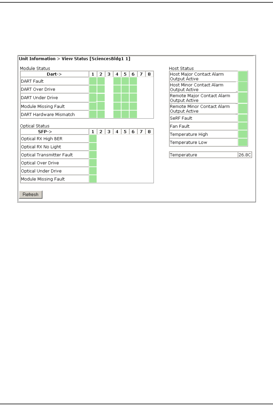
VIEWING THE STATUS OF THE HOST UNIT
1I n t he Syst em Tree, click on the Host icon.
2I n the Unit Menu bar, click Unit Information > View Status.
The Unit Information > View Status page provides the following inform ation for t he
select ed Host . The background of each t able cell is color coded t o t he level of the
alarm ; see “ Viewing Param eters and Alarm s” on page 44. For further inform ation
on t hese fault s and alarm s, see “ Troubleshoot ing Alarm s” on page 185.
•Module Status t able—provides st atus inform ation for inst alled DARTs, where
colum ns 1 through 8 correspond t o t he slot in which t he DART resides ( Colum n
1 = Slot 1, and so forth) . I f a DART colum n has no background color, a DART
is not installed in that slot .
–DART Fault—Sum m ary of DART Downconverter 1 Synt hesizer Unlocked,
Downconverter 2 Synt hesizer Unlocked, Upconvert er Synthesizer Unlocked,
DC Supply Fault alarm s, and DART FPGA stat us.
–DART Over Drive Fault—Red indicates t hat t he RF signal received from t he
BTS/ BDA is t oo st rong. Fault t hreshold is + 19 dBm .
–DART Under Drive Fault—DART forward RF input signal below the norm al
operating lim it . Fault t hreshold is + 5 - Fwd Gain - 20
–Module Missing Fault—One of t he Host pluggable m odules is m issing
( DART/ SFP).
–DART Hardware Mismatch—Host DART does not support the select ed passband.
Fault occurs when a Host DART is replaced wit h another DART of t he
incorrect t ype.
•Optical Status table—shows t he current usage and alarm st at us of the optical
port s on the Host plus t he current values of som e key operat ing param et ers.

Managing Unit s
FlexWave Prism Elem ent Managem ent Syst em 7.1 User Manual Page 155
ADCP- 77- 177 • I ssue 1 • July 2011 © 2011 ADC Telecom m unicat ions, I nc.
The Host has eight optical port s, but t he Optical Status table only shows act ive
port s (physically connect ed t o a Rem ot e) . Each port in t he table (where SFP 1
is colum n 1, SFP 2 is colum n 2, and so forth) represent s one set of forwar d and
reverse paths between a Host and Rem ot e. Physically, t his m ay have been
accom plished wit h a dual-connect or through that port . Each physical port
cont ains an SFP t ransceiver wit h t wo connectors.
The Optical Status t able only shows t he Receive power level from t he Rem ot e Unit
( REV pat h) . To see the Receive power level in the FWD pat h ( from t he Host t o
the Rem ot e), you m ust open the Unit Information > View Status page for t he desired
Rem ot e as described in “ Viewing t he St atus of a Rem ot e Unit ” on page 156.
–Optical RX High BER—High bit error rat e ( BER) detected by fiber opt ic receiver.
Fault threshold is 0.00001. Threshold cannot be changed.
–Optical RX No Light—No signal det ect ed by opt ical receiver.
–Optical Transmitter Fault—SFP opt ical t ransm itter failed.
–Optical Over Drive—SFP optical receive input power above specification. The
fault t hreshold cannot be changed, and is
1 dBm for I R
-9 dBm for LR.
–Optical Under Drive—SFP optical receive input power below specificat ion. The
fault t hreshold cannot be changed, and is
-18 dBm for I R
-27 dBm for LR.
–Module Missing Fault—One of t he Host SFPs is m issing.
•Host Status table—shows the current overall stat us of t he Host .
–Host Major Contact Alarm Output Active—Maj or Contact Alarm Output active.
–Host Minor Contact Alarm Output Active—Minor Cont act Alarm Output active.
–Remote Major Contact Alarm Output Active—Red indicat es NO/ NC m aj or alarm
cont act s are in an alarm posit ion. These connect ions are typically wired t o
a local alarm alert system . This st atus indicat or is red when a m aj or alarm
is present on any Rem ot e connected t o the Host .
–Remote Minor Contact Alarm Output Active—Yellow indicates that NO/ NC m inor
alarm contact s are in an alarm position. These connections are typically
wired t o a local alarm alert system . This st atus indicat or is yellow when a
m inor alarm is present on any Rem ot e connected t o Host.
–SeRF Fault—st ate of t he SeRF. Red indicat es t hat eit her t he SeRF clock source
is unacceptable or t he SeRF card FPGA is not program m ed.
–Fan Fault—st at e of t he Host chassis fan. Red indicat es t hat the Host chassis
fan is spinning t oo slowly.
–Temperature High—Red indicat es t hat t he current t em perat ure of t he Host
int erior is above it s operat ing lim it s. Fault t hreshold is 62° C.
–Temperature Low—Yellow indicates that t he current t em perat ure of the Host
int erior is below its operat ing lim it s. Fault t hreshold is 0° C.
•Temperature—Gives t he current t em perature of the Host chassis int erior in
degrees Centigrade, as det ect ed by t he Host .
View ing t he St at us of a Rem ot e Unit
Page 156 FlexWave Prism Elem ent Managem ent System 7.1 User Manual
© 2011 ADC Telecommunications, Inc ADCP-77- 177 • I ssue 1 • July 2011
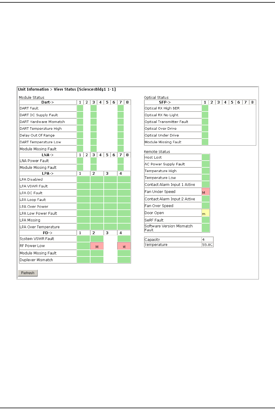
VIEWING THE STATUS OF A REMOTE UNIT
For furt her inform ation on t he faults listed in t he View Stat us page for Rem ot e
Units, see “ Troubleshoot ing Alarm s” on page 185.
1I n t he Syst em Tree, click on t he icon of the PRU/ URU for which you want t o
view it s st at us.
2I n the Unit Menu bar, click Unit Information > View Status.
The Unit Information > View Status page provides the following inform ation for t he
select ed Rem ot e Unit . The background of each t able cell is color coded t o the level
of t he alarm ; see “ Viewing Param eters and Alarm s” on page 44. For m ore
inform at ion on the fault s and alarm s, see “Troubleshoot ing Alarm s” on page 185.
Module Status Table
The Module Status t able provides st at us inform at ion for PRU/ URU m odules where
colum ns 1 t hrough 8 correspond t o the slot in which a DART resides ( see “ RF
Module Capabilit ies and GUI Represent at ion” on page 21) .
The following sect ions describe the different sections wit hin t he Module Status t able.
Managing Unit s
FlexWave Prism Elem ent Managem ent Syst em 7.1 User Manual Page 157
ADCP- 77- 177 • I ssue 1 • July 2011 © 2011 ADC Telecom m unicat ions, I nc.
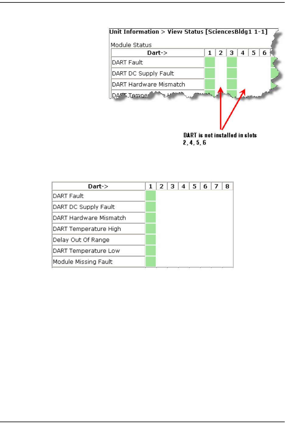
DART Status Table
The DART Status t able
presents stat us of the
DARTs in a Rem ot e Unit .
There can be bet ween 1
and 8 DARTs inst alled in a
Rem ot e Unit. I f a DART
colum n has no background
color, a DART is not
inst alled in that slot , as
shown below.
The DART Status t able has t he following elem ents.
•DART Fault—Sum m ary of DART Downconverter 1 Synt hesizer Unlocked,
Downconverter 2 Synt hesizer Unlocked, Upconvert er Synthesizer Unlocked,
DC Supply Fault alarm s, and DART FPGA stat us.
•DART DC Supply Fault—DART Module DC supply voltages out side specificat ion.
•DART Hardware Mismatch—Host DART does not support t he select ed passband.
Fault occurs when a Host DART is replaced wit h another DART of the incorrect
type.
•DART Temperature High—DART tem perat ure above operating lim it . Threshold is
85° C.
•Delay Out Of Range—PRU/ URU delay set t ings out side t he valid range.
•DART Temperature Low—DART t em perature below operating lim it . Threshold is
- 40° C.
•Module Missing Fault—DART m odule is m issing.
View ing t he St at us of a Rem ot e Unit
Page 158 FlexWave Prism Elem ent Managem ent System 7.1 User Manual
© 2011 ADC Telecommunications, Inc ADCP-77- 177 • I ssue 1 • July 2011
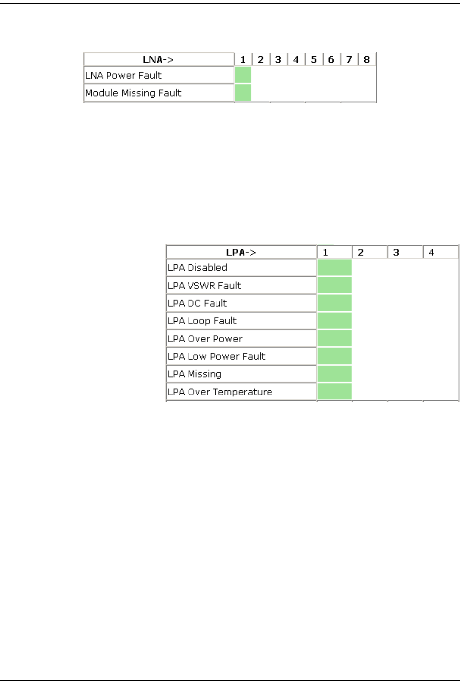
LNA Status Table
The LNA Status table present s st at us inform ation for t he Low Noise Am plifiers in a
Rem ot e Unit . There can be bet ween 1 and 8 LNAs inst alled in a Prism Rem ot e Unit .
•LNA Power Fault—PRU/ URU Low Noise Am plifier Power fault.
•Module Missing Fault—LNA m odule is m issing.
LPA Status Table
The LPA Status t able
presents stat us
inform ation for t he
Linear Power Am plifiers
in a Rem ote Unit. There
can be bet ween 1 and 4
LPAs inst alled in a Prism
Rem ot e Unit .
•LPA Disabled—PRU/ URU Linear Power Am plifier ( LPA) disabled due to an
int ernally det ect ed problem . (VSWR, DC, Loop Fault , Low Power, or
Tem perat ure High alarm ) .
•LPA VSWR Fault—PRU/ URU Linear Power Am plifier ( LPA) VSWR fault .
•LPA DC Fault—PRU/ URU Linear Power Am plifier ( LPA) DC fault .
•LPA Loop Fault—PRU/ URU Linear Power Am plifier ( LPA) Loop fault .
•LPA Over Power—PRU/ URU Linear Power Am plifier ( LPA) out put power level above
operating lim it .
•LPA Low Power Fault—I nt ernal Linear Power Am plifier ( LPA) Low Power fault . Gain
of one or m ore internal am plifiers out side of specificat ion) .
•LPA Missing—LPA m odule is m issing.
•LPA Over Temperature—PRU/ URU LPA above operat ing lim it .
Managing Unit s
FlexWave Prism Elem ent Managem ent Syst em 7.1 User Manual Page 159
ADCP- 77- 177 • I ssue 1 • July 2011 © 2011 ADC Telecom m unicat ions, I nc.
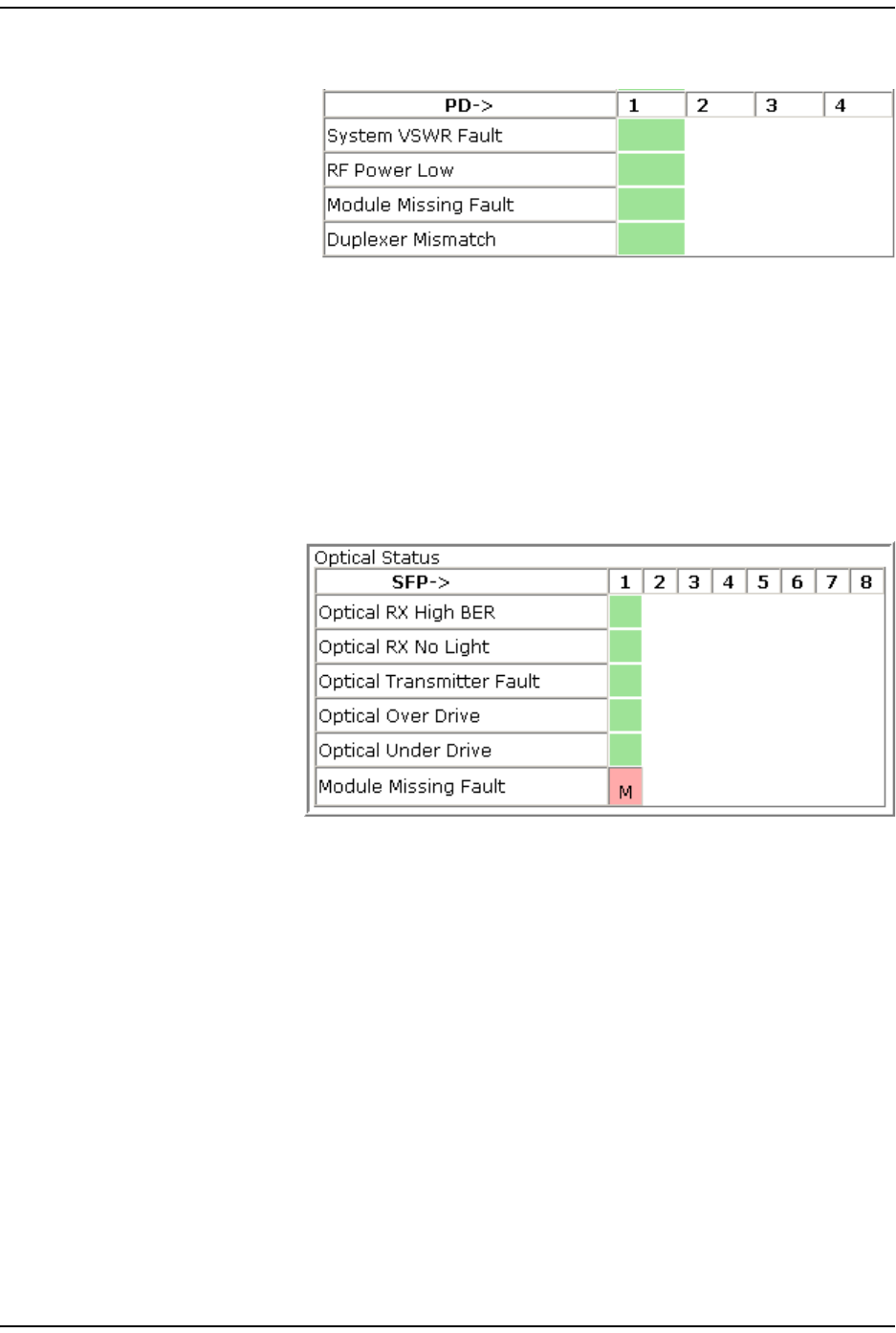
PD Status Table
The PD Status t able
presents stat us
inform ation for t he Power
Det ect or in a Rem ot e
Unit. There can be
between 1 and 4 PDs
inst alled in a Prism
Rem ot e Unit .
•System VSWR Fault—PRU/ URU VSWR m easurem ent above specificat ion.
•RF Power Low—PRU/ URU RF Out put Power below m inim um threshold.
•Module Missing Fault—Power Det ect or m odule is m issing.
•Duplexer Mismatch—Configured frequency range not support ed by Duplexer.
Optical Status Table
The Optical Status t able
provides st atus
inform ation for SFPs
inst alled in a Rem ot e
Unit ( PRU/ URU) .There
can be bet ween 1 and 8
SFPs inst alled in a
Rem ot e Unit . I f a
colum n has no
background color, an
SFP is not inst alled in
that slot .
•Optical RX High BER—High bit error rat e ( BER) det ect ed by fiber optic receiver.
Threshold is 0.00001.
•Optical RX No Light—No signal det ect ed by opt ical receiver.
•Optical Transmitter Fault—SFP opt ical t ransm itter failed.
•Optical Over Drive—SFP opt ical receive input power above specification.
Thresholds are as follows:
–1 dBm for I R
–-9 dBm for LR.
•Optical Under Drive—SFP optical receive input power below specification.
Thresholds are as follows:
–-18 dBm for I R
–-27 dBm for LR.
•Module Missing Fault—SFP m odule is m issing.
View ing t he St at us of a Rem ot e Unit
Page 160 FlexWave Prism Elem ent Managem ent System 7.1 User Manual
© 2011 ADC Telecommunications, Inc ADCP-77- 177 • I ssue 1 • July 2011
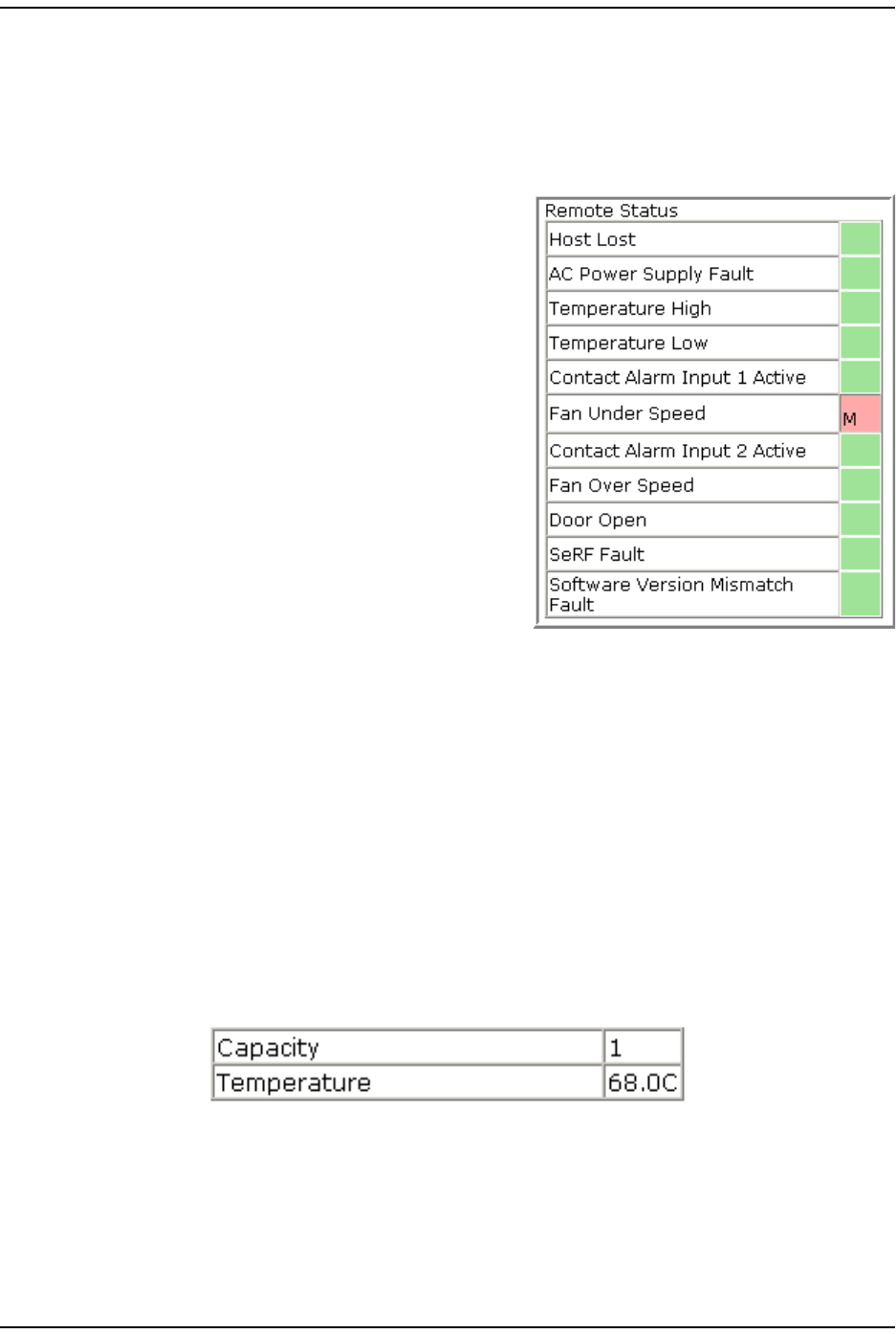
Remote Status Table
The Remote Status t able provides general st at us inform at ion for a Rem ot e Unit
( PRU/ URU) .
•Host Lost—Host is not com m unicating wit h
PRU/ URU.
•AC Power Supply Fault—Power supply is in a
failed st ate, or the AC power is below t he
m inim um required voltage.
•Temperature High—Tem perat ure above
operating lim it . Threshold is 95° C.
•Temperature Low—Tem perat ure below
operating lim it . Threshold is Minus 40° C.
•Contact Alarm Input 1 Active—Host Contact
Alarm I nput # 1 active.
•Fan Under Speed—Fans operating below
expect ed RPM.
•Contact Alarm Input 2 Active—Host Contact
Alarm I nput # 2 active.
•Fan Over Speed—Fans operating above
expect ed RPM.
•Door Open—Door open on PRU.
•SeRF Fault—Sum m ary of SeRF Synt hesizer Unlocked alarm and SeRF FPGA
st at us.
•Software Version Mismatch Fault—Soft ware version on the Host and Rem ot e Units do
not m atch.
Remote Unit Capacity and Temperature
The Unit Information > View Status page for Rem ot e Unit s also provides unit capacit y
and t em perat ure inform ation for the select ed Rem ot e Unit ( PRU/ URU) .
•Capacity—the num ber of RF groups available to t he Rem ot e Unit .
•Temperature—The int ernal Tem perat ure of the select ed unit .
Managing Unit s
FlexWave Prism Elem ent Managem ent Syst em 7.1 User Manual Page 161
ADCP- 77- 177 • I ssue 1 • July 2011 © 2011 ADC Telecom m unicat ions, I nc.
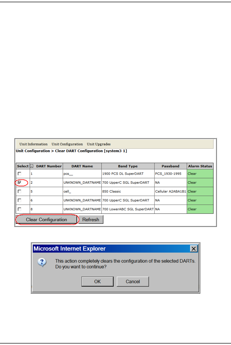
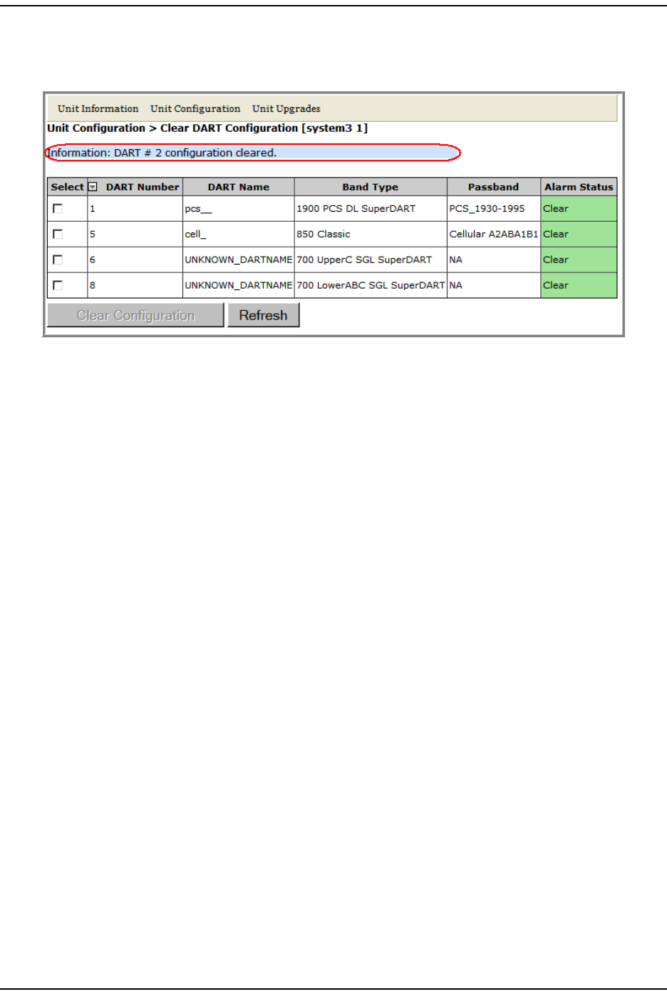
CLEARING DART CONFIGURATIONS
This procedure does the following:
•resets t he gain
•resets t he DART nam e
•clears all links
•clears the passband
•clears all associat ed alarm s
1I n t he Syst em Tree, click on an icon for a Host or Rem ot e Unit.
2I n t he Unit Menu bar, click Unit Configuration > Clear DART Configuration, t o open the
Clear DART Configuration page.
3I n t he Select colum n, select t he DART(s) for which you want t o clear
configurat ion.
4Click Clear Configuration.
5I n t he confirm at ion window, click OK.
Set t he Capacit y for a New Rem ot e Unit RSI Board
Page 162 FlexWave Prism Elem ent Managem ent System 7.1 User Manual
© 2011 ADC Telecommunications, Inc ADCP-77- 177 • I ssue 1 • July 2011
I f t he DART has been rem oved from t he Host or PRU/ URU chassis, then t he
ent ire DART ent ry disappears. I f the DART is st ill present in t he Host or
PRU/ URU chassis, t hen the DART Name and Passband is reset t o default.
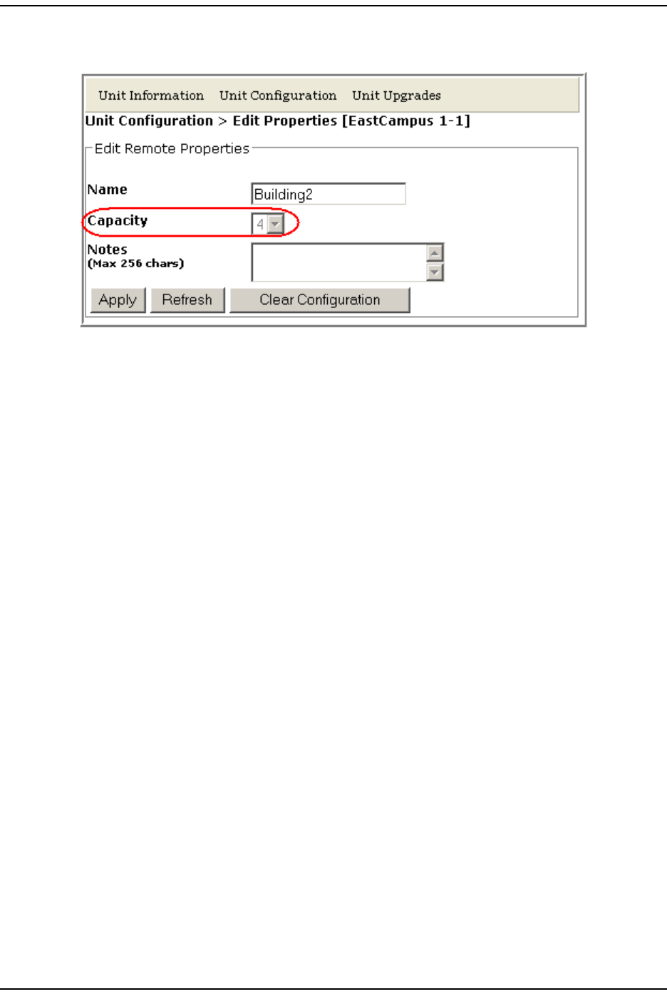
SET THE CAPACITY FOR A NEW REMOTE UNIT RSI BOARD
The Capacity set t ing in the Edit Properties page pert ains to t he PRU/ URU Rem ot e SeRF
I nt erface ( RSI ) board and t he num ber of RF groups available t o the Rem ot e Unit .
This param et er is set during m anufacturing and should be changed only when t he
RSI board has been replaced.
Using the EMS GUI to Change the Remote Unit Capacity
The Capacity setting can be changed by logging onto the EMS t hrough t he Rem ot e
Craft port .
1Open t he unit and connect your laptop t o t he Craft port on t he SeRF.
2Login to t he EMS, using t he following param eters:
•I P address is 192.168.0.1
•User Nam e is operator
•Password is operator
Managing Unit s
FlexWave Prism Elem ent Managem ent Syst em 7.1 User Manual Page 163
ADCP- 77- 177 • I ssue 1 • July 2011 © 2011 ADC Telecom m unicat ions, I nc.
3I n t he Syst em Tree, click the icon of the PRU/ URU whose propert ies you want
to change.
4I n t he Unit Menu bar, click Unit Configuration > Edit Properties, t o open the Unit
Configuration > Edit Properties page for t he select ed PRU.
5I n t he Capacity list , set the Capacity of t he new RSI board:
•For all RSI boards inst alled in a URH, Capacity should always be set t o 3.
•For an RSI board inst alled in a PRU, Capacity can be 1, 2, 3, or 4 and indicat es
the num ber of RF Modules inst alled in the PRU.
6Click Apply.
Using Telnet or ssh to Change the Remote Unit Capacity
Alt ernat ely, t he capacit y can be changed using Telnet or ssh.
1Access the Edit Unit Propert ies page to det erm ine t he I P address for the Host
and Rem ote Unit(s) . I n the Syst em Menu bar, click System Configuration > Edit Unit
Properties. Each row in t he Edit Unit Properties table correspond t o the unit
ident ified in the Unit Id colum n. Use the IP Address colum n to det erm ine t he I P
address for each unit .
2Login to t he Host using telnet or ssh.
3From t he Host , login t o the Rem ot e Unit using t he following com m and,where N
is t he Rem ot e Unit I D ( 1 - 8): sshremote N
4Once logged into t he Rem ot e Unit , execut e t he following com m and, where X is
the capacity ( 1-4) : /usr/local/fwu/bin/EEPROMWriteForCapacity.sh X
Reboot ing a Unit
Page 164 FlexWave Prism Elem ent Managem ent System 7.1 User Manual
© 2011 ADC Telecommunications, Inc ADCP-77- 177 • I ssue 1 • July 2011
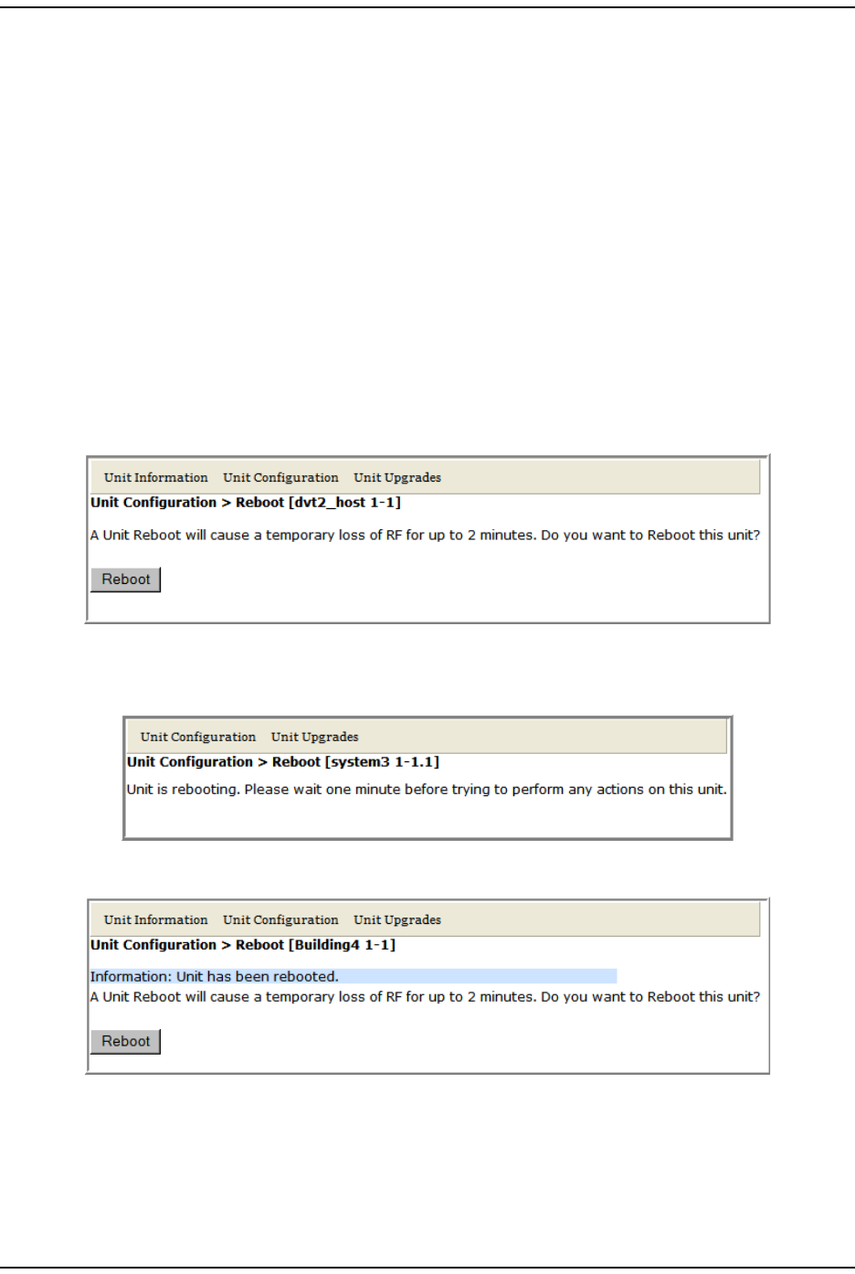
REBOOTING A UNIT
CAUTION! The system configuration is stored on the Host. Rebooting the Host therefore results in a
loss of RF for the Host and connected Remote Units until the Host comes back up.
Depending on the system configuration, it can take 5 to 20 minutes before management
communication is restored.
CAUTION! Host configuration persists across a Reboot. However, the current EMS session will close
and you will need to log back in to the EMS after the Host reboot has completed.
CAUTION! Rebooting a Remote Unit causes Loss of Service and should not be used unless other
troubleshooting processes have been followed and did not fix the issue being experienced
at the PRU/URU.
1I n the Syst em Tree, click on t he icon of the unit t hat you want t o reboot.
2I n t he Unit Menu bar, click Unit Configuration > Reboot, t o open the Unit Configuration
> Reboot page.
3Click Reboot.
•Once the reboot st art s, a process m essage displays.
•Aft er t he reboot has com plet ed, a Unit has been rebooted m essage displays.
•Aft er the Host reboots, the EMS login window opens.
Managing Unit s
FlexWave Prism Elem ent Managem ent Syst em 7.1 User Manual Page 165
ADCP- 77- 177 • I ssue 1 • July 2011 © 2011 ADC Telecom m unicat ions, I nc.
RESETTING AN LPA
CAUTION! Once an LPA Reset is started, Loss of Service occurs. It takes approximately 10 to 20
seconds before the LPA signal recovers. The GUI RF power reading will take longer
depending on the number of Remotes equipped—for a fully loaded Prism system with 8
Remotes the power reading could take several minutes to update.
NOTE: Only a user logged in under the admin or a Network Manager account can change Prism
system settings through the EMS.
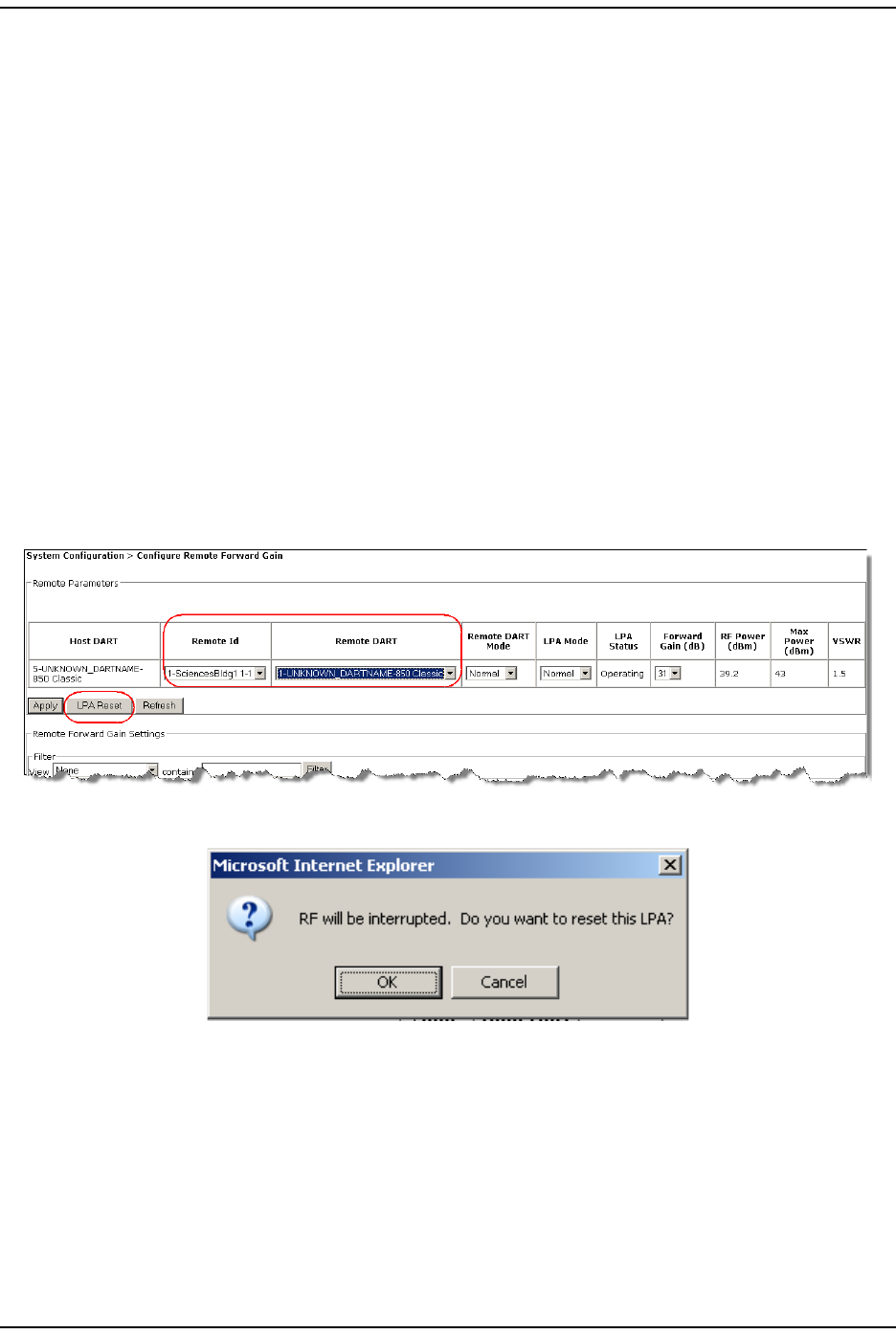
You use the LPA Reset but t on to bring an LPA back int o service ( restart) t hat
st opped because of a m aj or LPA alarm . I n a dual-LPA syst em , reset t ing the LPA
applies t o bot h LPAs at t he sam e tim e.
1To access the Configure Remote Forward Gain page, in t he Syst em Menu bar, click
System Configuration > Configure Remote Forward Gain.
2I n t he Remote Id list , select t he Rem ote Unit whose LPA you need to reset .
3I n t he Remote DART list , select t he DART whose LPA you need t o reset .
4Click t he LPA Reset but ton.
5I n the LPA Reset caution dialog, click OK.

Reset t ing an LPA
Page 166 FlexWave Prism Elem ent Managem ent System 7.1 User Manual
© 2011 ADC Telecommunications, Inc ADCP-77- 177 • I ssue 1 • July 2011
I nt ent ionally Blank Page

FlexWave Prism Elem ent Managem ent Syst em 7.1 User Manual Page 167
ADCP- 77- 177 • I ssue 1 • July 2011 © 2011 ADC Telecommunications, Inc.
ALARMS
View Current Alarm s.............................................................................................................168
Clear Current Alarm s ............................................................................................................170
View Alarm Hist ory ............................................................................................................... 170
Clear ing Alar m Hist ory ..........................................................................................................172
Filt ering the Alarm History.....................................................................................................172
Manage Alarm s.................................................................................................................... 174
Enable and Disable Host and Rem ot e Unit Alarm s ............................................................... 178
Set RF Power Low Threshold ............................................................................................ 180
Ant enna Disconnect Alarm ............................................................................................... 181
Manage Cont act Alarm s ........................................................................................................ 182
Acknowledge All Alarm s ........................................................................................................ 183
Clear All Disconnect Alarm s ................................................................................................... 184
Troubleshooting Alarm s ........................................................................................................ 185
Maj or Alarm s—Host Unit .................................................................................................. 185
Maj or Alarm s—Host Unit DARTs........................................................................................ 185
Maj or Alarm s—Host SeRF Modules .................................................................................... 187
Maj or Alarm s—Host Unit SFPs .......................................................................................... 188
Maj or Alarm s—Rem ot e Unit s ............................................................................................ 189
Maj or Alarm s—PRU/ URU DARTs........................................................................................ 189
Maj or Alarm s—PRU/ URU SeRF Modules.............................................................................. 191
Maj or Alarm s—PRU/ URU SFPs .......................................................................................... 193
Maj or Alarm s—PRU or URU Duplexer ................................................................................. 194
Maj or Alarm s—PRU or URU LNA........................................................................................ 194
Maj or Alarm s—PRU or URU LPA ........................................................................................ 195
Maj or Alarm s—PRU or URU Power Det ect or ........................................................................ 196
Minor Alarm s—Host Unit DARTs ........................................................................................ 197
Minor Alarm s—Host Unit SeRF Module ............................................................................... 197
Minor Alarm s—Host Unit SFPs .......................................................................................... 198
Minor Alarm s—PRU/ URU DARTs........................................................................................ 198
Minor Alarm s—PRU/ URU SeRF Modules.............................................................................. 199
Minor Alarm s—PRU/ URU SFPs .......................................................................................... 200
Minor Alarm s—PRU or URU LPAs ....................................................................................... 200
Cont act Alarm s—Host Syst em Card ................................................................................... 201
Cont act Alarm s—Rem ot e Unit .......................................................................................... 201
This sect ion describes how t o m anage and underst and t he alarm s that are
report ed by t he EMS. This sect ion also provides corresponding Trap nam es.
Topics Page
View Current Alar m s
Page 168 FlexWave Prism Elem ent Managem ent System 7.1 User Manual
© 2011 ADC Telecommunications, Inc ADCP-77- 177 • I ssue 1 • July 2011
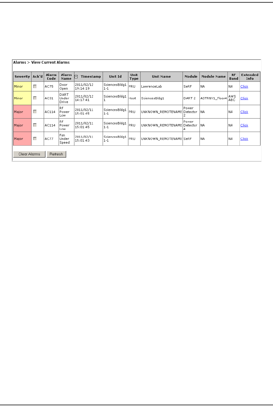
VIEW CURRENT ALARMS
To access the View Current Alarms page, in t he System Menu bar, click Alarms > View
Current Alarms. ( For inform ation on the alarm color codes, see “ Alarm Color Codes”
on page 44.)
The View Current Alarms t able provides the following inform at ion:
•Severity—whet her t he alarm is classified as Maj or or Minor.
•Ack’d—whether the alarm has been acknowledged, as indicat ed by a
checkm ark.
•Alarm Code—system -assigned alarm code.
•Alarm Name—descriptive nam e of alarm .
•Timestamp—dat e and tim e when the alarm occurred (YYYY:MM:DD:HH:MM:SS)
•Unit Id—ident ifies t he unit wit hin the syst em t hat raised t he alarm ; see “ Unit
I dent ification” on page 43.
•Unit Type—what t he unit is, such as Host or Rem ot e
•Unit Name—nam e assigned t o the unit
•Module—type of m odule that is experiencing t he alarm ( SeRF, DART, LPA, LNA,
Power Det ect or, SFP)
•Module Name—user- assigned nam e for the m odule.
•RF Band—type of passband provided by the DART.
Alar m s
FlexWave Prism Elem ent Managem ent Syst em 7.1 User Manual Page 169
ADCP- 77- 177 • I ssue 1 • July 2011 © 2011 ADC Telecom m unicat ions, I nc.
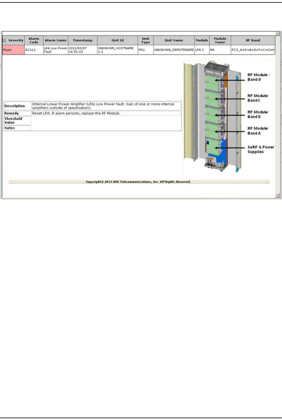
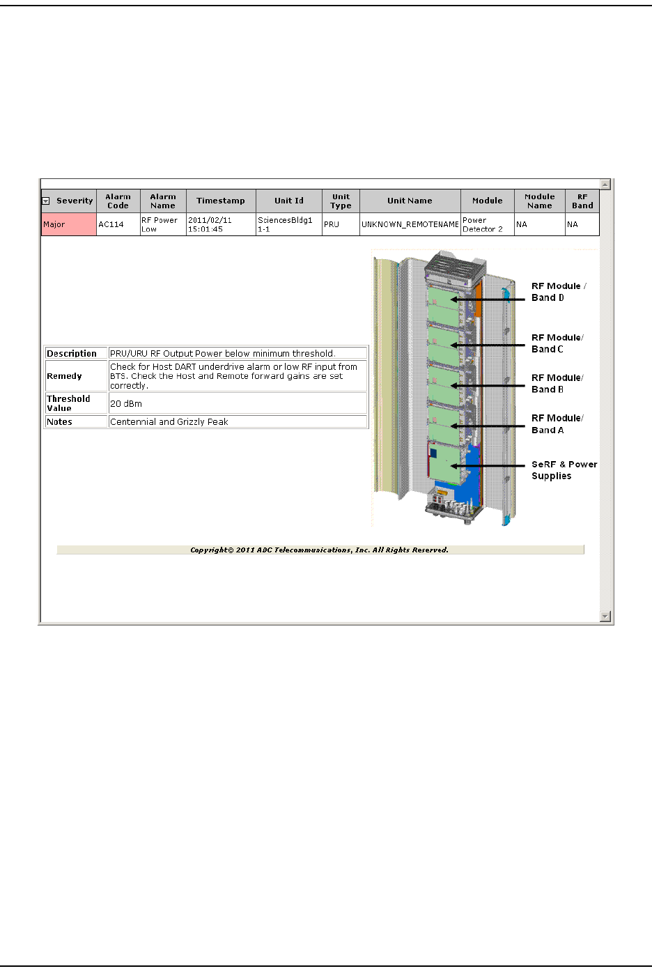
•Extended Info—link t hat once clicked opens anot her web page, which provides
furt her inform ation on t he alarm , including troubleshooting inform at ion, as
shown in t he following graphic.
–Description—text description of alarm
–Remedy—what you can do t o correct t he alarm st at e
–Threshold—value t hat once surpassed generat es an alarm
–Notes—user- defined notes, if any, for the unit .
Clear Current Alarm s
Page 170 FlexWave Prism Elem ent Managem ent System 7.1 User Manual
© 2011 ADC Telecommunications, Inc ADCP-77- 177 • I ssue 1 • July 2011
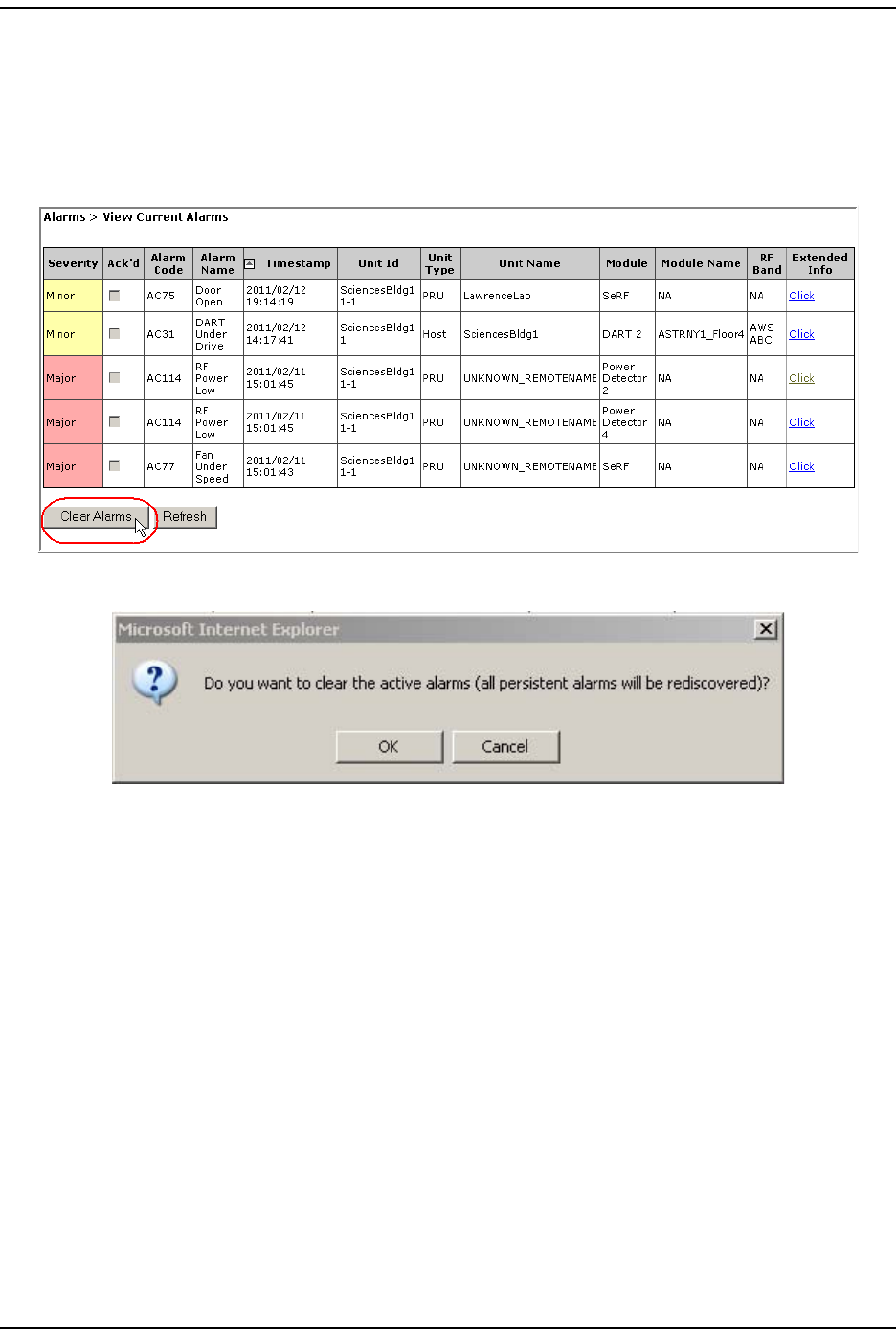
CLEAR CURRENT ALARMS
1To access the View Current Alarms page, in the Syst em Menu bar, click Alarms >
View Current Alarms.
2I n t he View Current Alarms page, click Clear Alarms.
3I n t he confirm at ion window, click OK.
All current alarm s, wit h t he except ion of persist ent alarm s, are cleared from
the View Current Alarms t able.
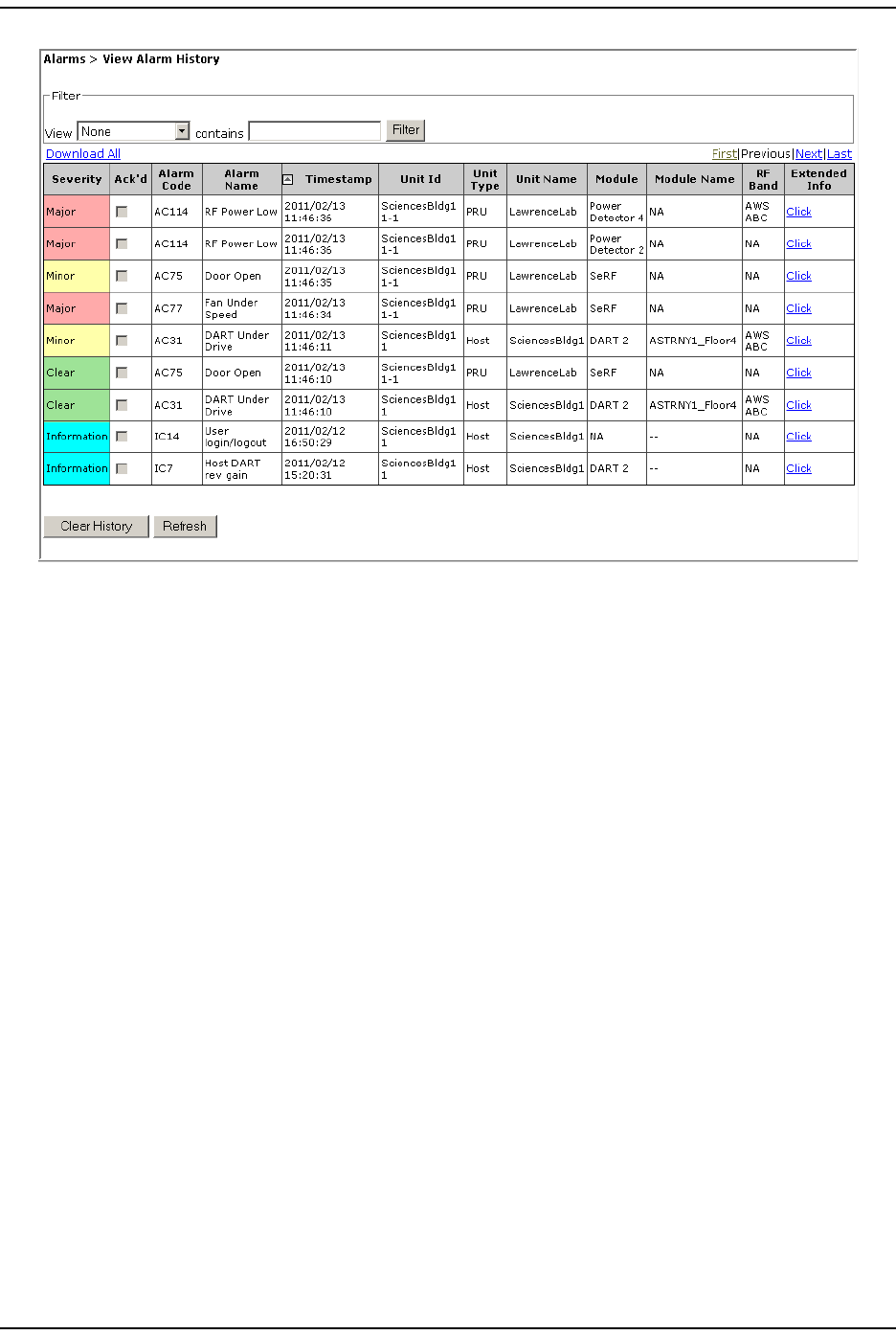
VIEW ALARM HISTORY
To access the View Alarm History page, in t he System Menu bar, click Alarms > View
Alarm History. ( For inform ation on t he alarm color codes, see “ Alarm Color Codes”
on page 44.)
Alar m s
FlexWave Prism Elem ent Managem ent Syst em 7.1 User Manual Page 171
ADCP- 77- 177 • I ssue 1 • July 2011 © 2011 ADC Telecom m unicat ions, I nc.
The View Alarm History table provides the following inform ation:
•Severity—whet her t he alarm is classified as Major or Minor.
•Ack’d—whet her t he alarm has been acknowledged, as indicated by a
checkm ark.
•Alarm Code—system -assigned alarm code.
•Alarm Name—descriptive nam e of alarm .
•Timestamp—dat e and t im e when the alarm occurred (YYYY:MM:DD:HH:MM:SS)
•Unit Id—ident ifies t he unit wit hin the syst em t hat raised t he alarm ; see “ Unit
I dent ification” on page 43.
•Unit Type—what t he unit is, such as Host or Rem ot e
•Unit Name—nam e assigned t o the unit
•Module—type of m odule that is experiencing t he alarm ( SeRF, DART, LPA, LNA,
Power Det ect or, SFP)
•Module Name—user- assigned nam e for the m odule.
•RF Band—type of passband provided by the DART.
•First, Previous, Last but tons—if t he View Alarm History t able is longer t han what can
fit on a single web page, First, Previous, Last but tons are included:
–First—j um ps the display t o the first page of alarm s
–Previous—jum ps t he display to t he page of alarm s that you viewed
im m ediat ely prior to t he current page
–Last—j um ps t he display t o the last page of alarm s
•Clear History but t on—see “ Clearing Alarm Hist ory” on page 172.
Clearing Alarm History
Page 172 FlexWave Prism Elem ent Managem ent System 7.1 User Manual
© 2011 ADC Telecommunications, Inc ADCP-77- 177 • I ssue 1 • July 2011
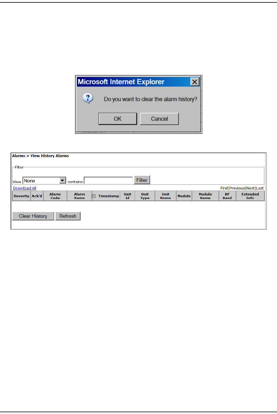
CLEARING ALARM HISTORY
1To access the View Alarm History page, in the Syst em Menu bar, click Alarms > View
Alarm History.
2Click Clear History.
3I n t he confirm at ion window, click OK.
The View Alarm History page is cleared.
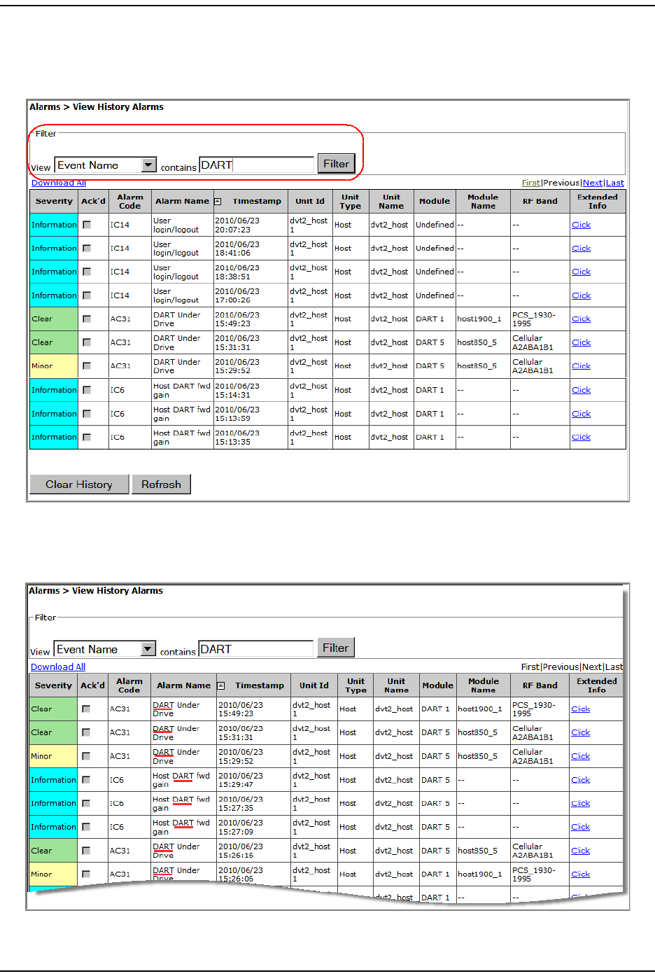
FILTERING THE ALARM HISTORY
The View Alarm History page allows you t o filt er, or select, which alarm hist ories you
want t o page.
1To access the View Alarm History page, in the Syst em Menu bar, click Alarms > View
Alarm History.
2Do t he following in t he Filter panel:
aI n t he View list , select how you want to filt er the alarm s:
•None—all alarm s display
•Unit Name—filt er by the user- assigned nam e of a unit
•Host Number—filt er by t he syst em -assigned num ber for the Host
•Remote Number—filter by t he system -assigned num ber for a Rem ote
•Event Name—filter by an event ( alarm or incident) nam e.
Alar m s
FlexWave Prism Elem ent Managem ent Syst em 7.1 User Manual Page 173
ADCP- 77- 177 • I ssue 1 • July 2011 © 2011 ADC Telecom m unicat ions, I nc.
bI n t he contains box, ent er t he crit eria by which you want t o filt er t he alarm
hist ory list .
cClick Filter.
The View Alarm History page refreshes, and now lists only t hose alarm s that m eet
the specified filter crit eria. I n t his exam ple, only t hose event s wit h t he word
“ DART” in them display.

Manage Alarm s
Page 174 FlexWave Prism Elem ent Managem ent System 7.1 User Manual
© 2011 ADC Telecommunications, Inc ADCP-77- 177 • I ssue 1 • July 2011
3To rem ove the filt er:
aI n t he View list , select None.
bDelet e any text from t he contains box.
cClick Filter.
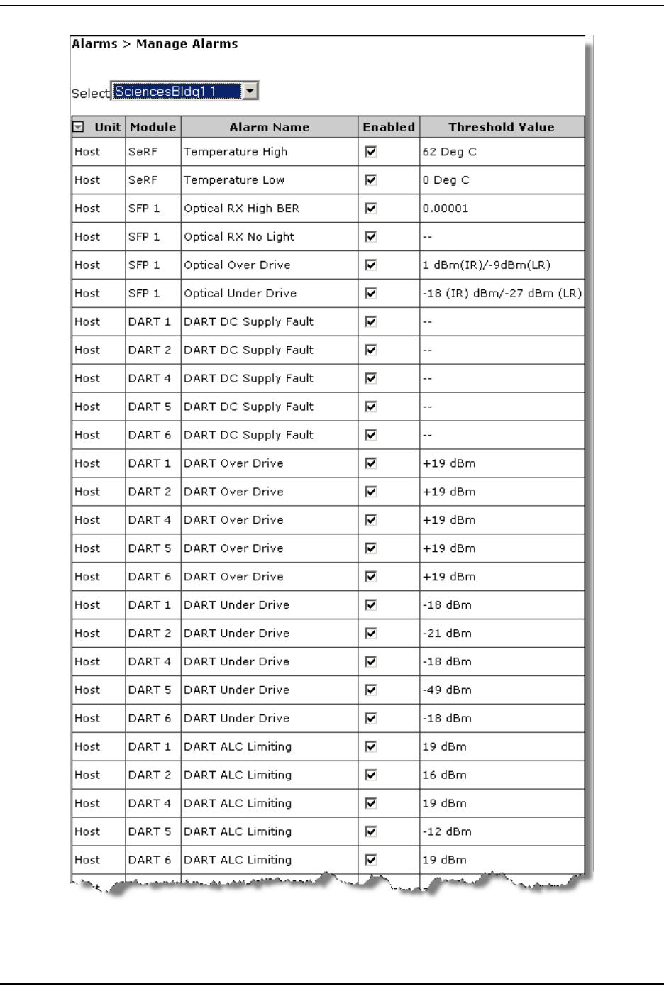
MANAGE ALARMS
To access the Manage Alarms page, in the Syst em Menu bar, click Alarms > Manage
Alarms.
•For an exam ple of a Manage Alarms page for a Host Unit , see Figure 23 on
page 175 and Figur e 24 on page 176.
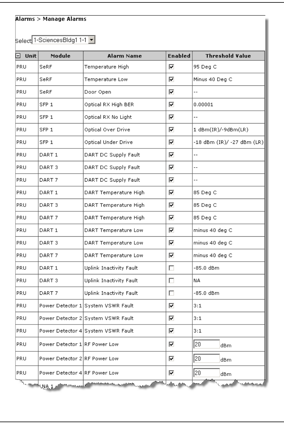
•For an exam ple of a Manage Alarms page for a Rem ot e Unit , see Figure 25 on
page 177 and Figure 26 on page 178.
The Manage Alarms page has t he following elem ent s:
•Select m enu—has t he following im plem entat ions:
–Global—displays alarm s for t he Host and all connect ed Rem ot e Unit s. Please
not e, however, that this view does not reflect t he current st at us of alarm
enable/ disable condit ions—it is designed t o show you at a glance those
alarm s that can be m anaged. To effect a change in the m anagem ent of an
alarm and t o see the current st ate of an alarm , select a specific unit .
–Unit name—each unit in the syst em is list ed by nam e, which allows you t o
select for which unit you want t o m anage alarm s.
•Antenna Disconnect Severity m enu—see “ Antenna Disconnect Alarm ” on page 181.
•Unit field—what t ype of unit t he alarm pert ains t o:
–Host
–Remote
•Module field—which m odule t he alarm pertains to:
–DART—can be up to eight DARTs listed
–LNA—can be up t o t wo LNAs list ed
– Power Detector
–SFP—can be up t o eight SFPs list ed
–SeRF
•Alarm Name field—identifies the alarm by nam e; see Table 23 on page 178.
NOTE: For definitions of the alarms listed above, see “Troubleshooting Alarms” on page 185.
•Enabled select ion box—select to enable alarm reporting for t he corresponding
alarm .
•Threshold Value field—value that once surpassed generat es the specified alarm ;
see Table 23 on page 178.

Alar m s
FlexWave Prism Elem ent Managem ent Syst em 7.1 User Manual Page 175
ADCP- 77- 177 • I ssue 1 • July 2011 © 2011 ADC Telecom m unicat ions, I nc.
Figure 23. Example of Manage Alarms Page—Host Unit Part 1
Manage Alarm s
Page 176 FlexWave Prism Elem ent Managem ent System 7.1 User Manual
© 2011 ADC Telecommunications, Inc ADCP-77- 177 • I ssue 1 • July 2011
Figure 24. Example of Manage Alarms Page—Host Unit Part 2
Alar m s
FlexWave Prism Elem ent Managem ent Syst em 7.1 User Manual Page 177
ADCP- 77- 177 • I ssue 1 • July 2011 © 2011 ADC Telecom m unicat ions, I nc.
Figure 25. Example of Manage Alarms Page—Remote Unit Part 1
Manage Alarm s
Page 178 FlexWave Prism Elem ent Managem ent System 7.1 User Manual
© 2011 ADC Telecommunications, Inc ADCP-77- 177 • I ssue 1 • July 2011
Figure 26. Example of Manage Alarms Page—Remote Unit Part 2
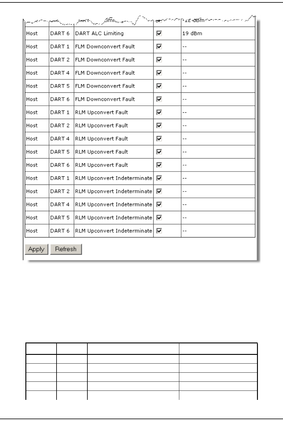
Enable and Disable Host and Remote Unit Alarms
The Manage Alarms page allows you t o enable and disable alarm reporting for t he
alarm s list ed in Table 23 on page 178.
Table 23. Alarms That Can Be Enabled/Disabled
Unit Module Alarm Alarm Threshold
Remote RDI AC Power Supply 1 Fault
Remote RDI AC Power Supply 2 Fault
Remote RDI AC Power Supply 3 Fault
Remote RDI AC Power Supply 4 Fault
Remote PRU/URU AC Power Supply Fault

Alar m s
FlexWave Prism Elem ent Managem ent Syst em 7.1 User Manual Page 179
ADCP- 77- 177 • I ssue 1 • July 2011 © 2011 ADC Telecom m unicat ions, I nc.
Host DART DART ALC Limiting +19 - Fwd Gain dBm
Host DART DART DC Supply Fault
Remote DART DART DC Supply Fault
Host DART DART Over Drive +19 dBm
Remote DART DART Temperature High 85 Deg C
Remote DART DART Temperature Low minus 40 deg C
Host DART DART Under Drive +5 - Fwd Gain - 20 dBm
Remote SeRF Door Open
Remote DART Downconvert Fault
Remote DART DART DC Supply Fault
Remote SFP Excess Connections
Host DART FLM Downconvert Fault
Remote DART FWD Cal Tone Fault
Remote SFP Invalid Device Connection
Remote LNA LNA Power Fault
Host SFP Optical Over Drive 1 dBm(IR)/-9dBm(LR)
Remote SFP Optical Over Drive 1 dBm(IR)/-9dBm(LR)
Host SFP Optical RX High BER 0.00001
Remote SFP Optical RX High BER 0.00001
Host SFP Optical RX No Light
Remote SFP Optical RX No Light
Host SFP Optical Under Drive -18 (IR) dBm/-27 dBm (LR)
Remote SFP Optical Under Drive -18 dBm (IR)/ -27 dBm (LR)
Remote DART REV Test Tone Low
Remote PD RF Power Low 0 dBm*
Host DART RLM Upconvert Fault
Host DART RLM Upconvert Indeterminate
Remote SeRF Software Version Mismatch Fault
Remote PD System VSWR Fault 3:1
Host SeRF Temperature High 62 Deg C
Remote SeRF Temperature High 95 Deg C
PRU/URU SeRF Temperature High 62 Deg C
Host SeRF Temperature Low 0 Deg C
Remote SeRF Temperature Low Minus 40 Deg C
PRU/URU SeRF Temperature Low 0 Deg C
Remote LPA Under Power
Remote DART Upconvert Fault
Remote DART Upconvert Indeterminate
Remote DART Uplink Inactivity Fault 10 dB above the noise floor.
* You can manually set the threshold for RF Power Low; see “Set RF Power Low Threshold” on page 180
Table 23. Alarms That Can Be Enabled/Disabled (Cont.)
Unit Module Alarm Alarm Threshold

Manage Alarm s
Page 180 FlexWave Prism Elem ent Managem ent System 7.1 User Manual
© 2011 ADC Telecommunications, Inc ADCP-77- 177 • I ssue 1 • July 2011
Do t he following t o enable/ disable alarm report ing:
1To access the Manage Alarms page, in the Syst em Menu bar, click Alarms > Manage
Alarms.
2I n t he Select list , select the Rem ot e Unit for which you want t o change the
threshold of the RF Power Low alarm .
3I n t he Threshold Value box for t he RF Power Low alarm , ent er the new t hreshold,
which m ust be bet ween 0 dB - 40 dB.
4Click Apply.
Set RF Power Low Threshold
The following rules apply to set t ing alarm t hresholds:
•Only the t hreshold for the RF Power Low alarm can be changed.
•Only users wit h Network Manager or Adm in privileges can perform t his
procedure.
•Alarm t hresholds cannot be set t hrough SNMP MI Bs.
•I f you perform a Reset to Factory Defaults, t he alarm t hreshold values are reset;
you will need t o be reconfigure the alarm t hreshold values, as necessary.
•Alarm t hreshold values are configured by unit —t hey cannot be set globally for
all units in t he syst em .
Do t he following t o set t he RF Power Low alarm t hreshold:
1To access the Manage Alarms page, in the Syst em Menu bar, click Alarms > Manage
Alarms.
2I n t he Select list , select the Rem ot e Unit for which you want t o change the
threshold of the RF Power Low alarm .
3I n t he Threshold Value box for t he RF Power Low alarm , ent er the new t hreshold,
which m ust be bet ween 0 dB - 40 dB.
4Click Apply.
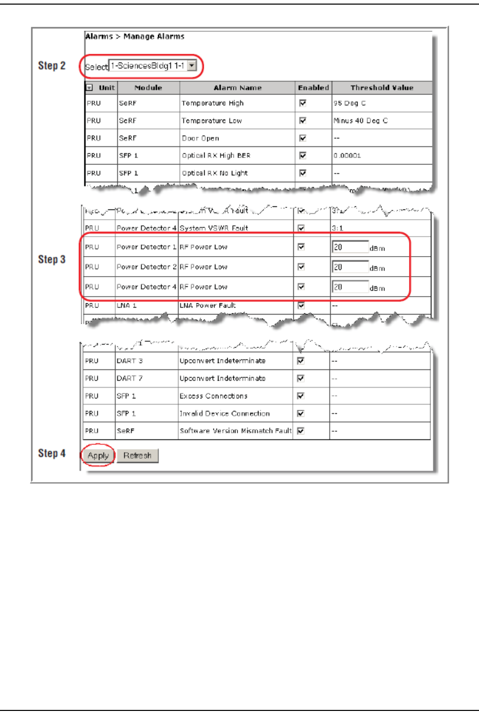
Alar m s
FlexWave Prism Elem ent Managem ent Syst em 7.1 User Manual Page 181
ADCP- 77- 177 • I ssue 1 • July 2011 © 2011 ADC Telecom m unicat ions, I nc.
Antenna Disconnect Alarm
I n t he Manage Alarms page, t here is an Antenna Disconnect Severity m enu, which pert ains
only t o Rem ot e Access Unit s ( RAUs) in an I nt erReach Spectrum system . This
feature is therefore not applicable t o a FlexWave Prism syst em and should not be
changed from its default setting.
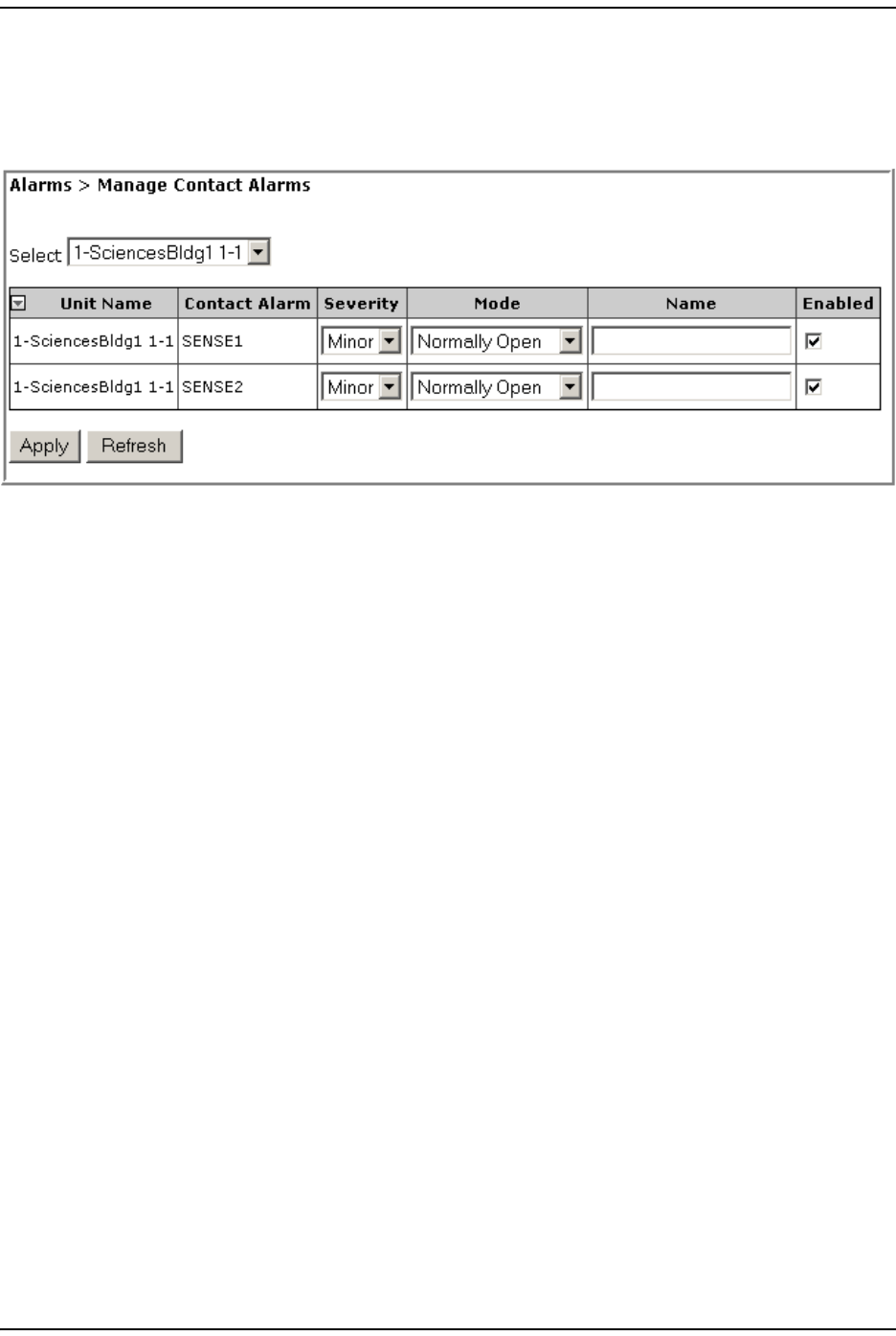
Manage Cont act Alarm s
Page 182 FlexWave Prism Elem ent Managem ent System 7.1 User Manual
© 2011 ADC Telecommunications, Inc ADCP-77- 177 • I ssue 1 • July 2011
MANAGE CONTACT ALARMS
1To access the Manage Contact Alarms page, in t he Syst em Menu bar, click Alarms >
Manage Contact Alarms.
2I n t he Select m enu, select for which unit cont act alarm s are t o be configured.
The Manage Contact Alarms page has the following Read- Only elem ents:
•Unit Name—nam e assigned t o the unit
•Contact Alarm—nam e assigned t o t he cont act alarm
3I n t he Severity list , set t he severit y level of t he cont act alarm :
•Minor ( default )
•Major
4I n t he Mode list , set the m ode for t he cont act alarm :
•Normally Open (default)
•Normally Closed
5I n t he Name box, enter a nam e for t his alarm .
•Ent er bet ween 1 and 255 alphanum eric charact ers. Spaces and
Underscores are allowed, except they cannot be used as t he first charact er.
•I f you do not want t o nam e the alarm , leave t he Name box em pt y.
6I n t he Enabled select ion box for t he alarm t hat you want t o m anage, do one of
the following:
•Select the Enabled checkbox t o enable alarm reporting for this alarm t ype.
•Rem ove (deselect ) t he checkm ark from t he Enabled checkbox t o disable
alarm reporting for t his alarm type.
7Click Apply.
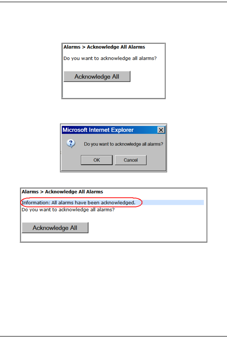
Alar m s
FlexWave Prism Elem ent Managem ent Syst em 7.1 User Manual Page 183
ADCP- 77- 177 • I ssue 1 • July 2011 © 2011 ADC Telecom m unicat ions, I nc.
ACKNOWLEDGE ALL ALARMS
1To access the Acknowledge All Alarms page, in t he Syst em Menu bar, click Alarms >
Acknowledge All Alarms.
2Click Acknowledge All.
3I n t he confirm at ion window, click OK.
An All alarms have been acknowledged m essage displays.
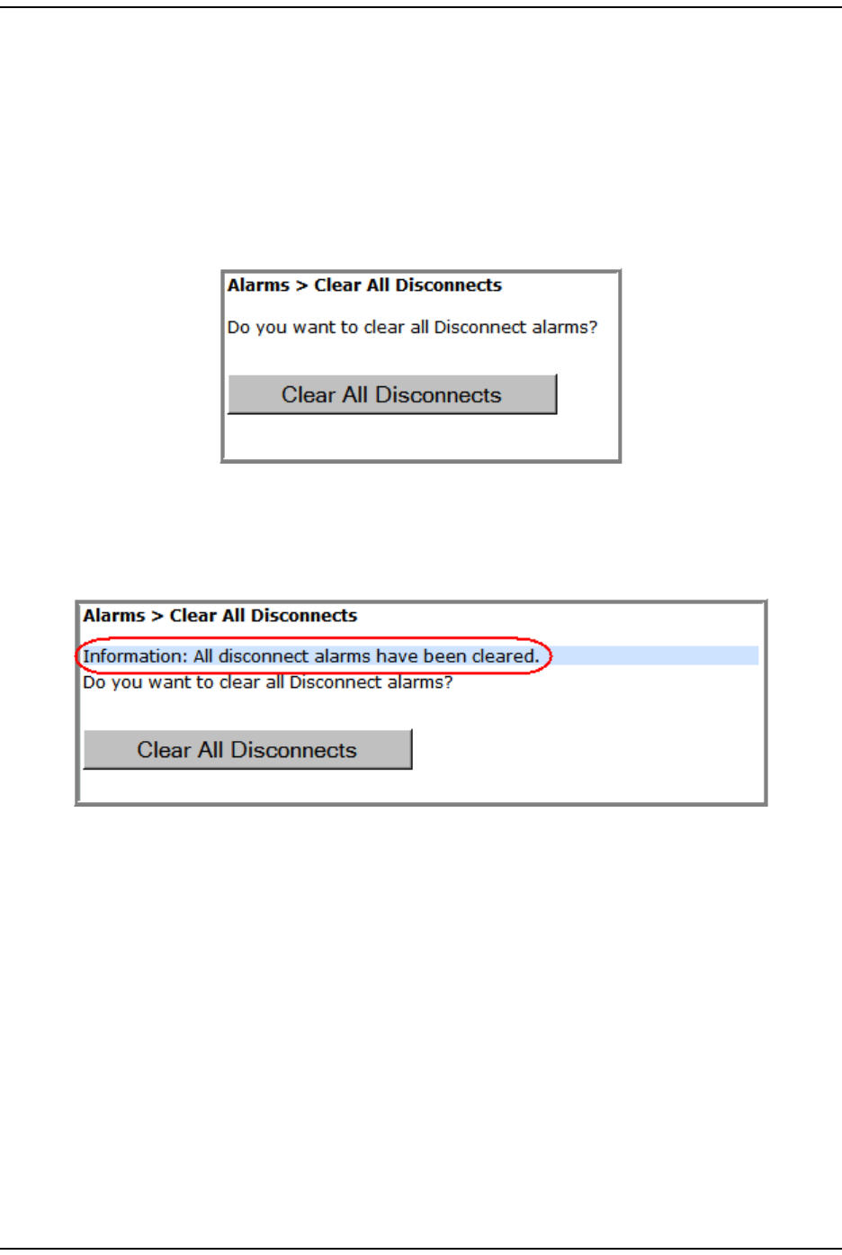
Clear All Disconnect Alarm s
Page 184 FlexWave Prism Elem ent Managem ent System 7.1 User Manual
© 2011 ADC Telecommunications, Inc ADCP-77- 177 • I ssue 1 • July 2011
CLEAR ALL DISCONNECT ALARMS
NOTE: Clear All Disconnects is not applicable to the Host—it is applicable only to PRUs.
CAUTION! This procedure removes all information related to the disconnected units from the
configuration database.
1To access the Clear All Disconnects page, in t he Syst em Menu bar, click Alarms >
Clear All Disconnects.
2Click Clear All Disconnects.
Aft er approxim at ely one m inute, t he Syst em Tree updates by rem oving t he
disconnect overlay from t he unit icon( s) . ( For an exam ple of t he disconnect
overlay, see Table 11 on page 42.)

Alar m s
FlexWave Prism Elem ent Managem ent Syst em 7.1 User Manual Page 185
ADCP- 77- 177 • I ssue 1 • July 2011 © 2011 ADC Telecom m unicat ions, I nc.
TROUBLESHOOTING ALARMS
This sect ion list s and defines alarm s that t he FlexWave Prism EMS reports, and
provides rem edies for t hose alarm s. The MI B Trap nam e for each alarm is also
list ed.
Major Alarms—Host Unit
Ala rm : Rem ot e Lost
Trap: fwuHstSERFRmtLostFault
Alarm Code: AC1
Definition: Rem ot e Unit ( PRU/ URU) not com m unicating wit h Host .
Remedy: Check t hat the PRU/ URU has power and t hat the power swit ch is on.
Check t hat at least one Host SFP is connect ed t o t his PRU/ URU and
has acceptable RX power.
Major Alarms—Host Unit DARTs
Ala rm : DART D C Supply Fault
Trap: fwuHstDARTDCSupplyFault
Alarm Code: AC28
Definition: DART card DC supply volt ages outside specificat ion.
Remedy: Check whether the Host supply volt age is in the range of 21-60 VDC.
I f t he volt age is correct and the alarm persists for 5 m inutes (m ay be
transient on st art up) , replace the DART.
Ala rm : DART D ow nconvert e r 1 Syn thesizer Unlocked
Trap: fwuHstDARTDwnCon1SynLockFault
Alarm Code: AC25
Definition: DART downconvert er 1 synt hesizer unlocked.
Remedy: The Downconverter 1 Synt hesizer Unlocked alarm can occur during
Host reboot s and DART hotswaps. I f the alarm persists aft er 5
m inutes, replace the DART.
Ala rm : DART D ow nconvert e r 2 Synthesize r Unlock ed
Trap: fwuHstDARTDwnCon2SynLockFault
Alarm Code: AC26
Definition: DART downconvert er 2 synt hesizer unlocked.
Remedy: The Downconverter 2 Synt hesizer Unlocked alarm can occur during
Host reboot s and DART hotswaps. I f the alarm persists aft er 5
m inutes, replace the DART.

Troubleshoot ing Alarm s
Page 186 FlexWave Prism Elem ent Managem ent System 7.1 User Manual
© 2011 ADC Telecommunications, Inc ADCP-77- 177 • I ssue 1 • July 2011
Ala rm : DART Fault
Trap: fwuHstDARTFault
Alarm Code: AC29
Definition: Sum m ary of DART Downconverter 1 Synt hesizer Unlocked,
Downconverter 2 Synt hesizer Unlocked, Upconvert er Synthesizer
Unlocked, DC Supply Fault alarm s, and DART FPGA st at us.
Remedy: I nspect alarm s (Alarms > View Current Alarms) for
upconvert er/ downconvert er/ DC supply alarm s on the sam e Host
DART and follow t he rem edies for t hose alarm s. I f none of these
alarm s are found, unplug and replug t he DART in the Host . I f t he
alarm persist s, replace the DART.
Ala rm : DART H a rdw ar e Mism atch
Trap: fwuHstDARTHardwareMismatchFault
Alarm Code: AC32
Definition: Host DART does not support t he selected passband. Fault occurs
when a Host DART is replaced wit h another DART of t he incorrect
type.
Remedy: I nst all a DART t hat supports the select ed passband. I f t he Host DART
position is t o be changed t o a different frequency band, rem ove and
clear the DART configuration (Unit Configuration > Clear DART Configuration) ,
inst all the new DART, set t he passband, and establish the new link
(System Configuration > Configure DART Links) .
Ala rm : DART Ove r Dr ive
Trap: fwuHstDARTOverDriveFault
Alarm Code: AC30
Definition: DART forward RF input too high.
Threshold: + 19 dBm
Remedy: Reduce the Host DART forward RF input level.
Ala rm : DART Upcon vert er Synt hesizer Unlocked
Trap: fwuHstDARTUpConSynLockFault
Alarm Code: AC27
Definition: DART upconvert er synt hesizer unlocked.
Remedy: The DART Upconvert er Synt hesizer Unlocked alarm can occur during
Host reboot s and DART hotswaps. I f the alarm persists aft er 5
m inutes, replace the DART.
Ala rm : FLM D ow ncon vert er Fa ult
Trap: fwuHstBTSFLMFailFault
Alarm Code: AC47
Definition: Forward Link Monit or ( FLM) fault active.
Remedy: I f alarm persist s, then replace the DART.

Alar m s
FlexWave Prism Elem ent Managem ent Syst em 7.1 User Manual Page 187
ADCP- 77- 177 • I ssue 1 • July 2011 © 2011 ADC Telecom m unicat ions, I nc.
Ala rm : M odule M issing Fault
Trap: fwuHstModuleMissingFault
Alarm Code: AC2
Definition: One of t he Host pluggable m odules is m issing (DART/ SFP) .
Remedy: Eit her replace Host m odule or clear DART configuration ( Unit
Configuration > Clear DART Configuration) .
Ala rm : RLM Upcon vert Fault
Trap: fwuHstRLMUpconvertFailureFault
Alarm Code: AC48
Definition: Reverse Link Monit or ( RLM) fault act ive.
Remedy: Running Syst em Test ( System Configuration > Perform System Test) wit h
un- t erm inat ed Host DARTs m ay cause a false RLM Upconvert Fault.
Ensure that all Host DARTs are t erm inated before running Syst em
Test . I f alarm persist s, then replace t he DART.
Major Alarms—Host SeRF Modules
Ala rm : Fa n Fa ult
Trap: fwuHstSysCardFanFault
Alarm Code: AC6
Definition: Fan not funct ioning.
Remedy: Verify intake and exhaust vent s are clear of obst ruct ions and/ or
debris. I f alarm persists, replace Fan Module.
Ala rm : Se RF Fa ult
Trap: fwuHstSERFFault
Alarm Code: AC10
Definition: Sum m ary of SeRF Synt hesizer Unlocked alarm and SeRF FPGA
st at us.
Remedy: Check for relat ed Host SeRF alarm s (Alarms > View Current Alarms) . I f no
SeRF alarm s exist , FPGA is faulty; replace Host SeRF Module.
Ala rm : SeRF Synt he sizer Unlock e d
Trap: fwuHstSERFSynthAlarmFault
Alarm Code: AC9
Definition: SeRF synthesizer unlocked.
Remedy: Check Host reference clock set t ings (Unit Configuration > Edit Properties) .
Reseat t he Syst em Module. I f reference clock source is external,
ver ify 10 MHz clock source and connect ion. I f reference clock source
is internal and the alarm s persist s, replace t he Host Syst em Module.

Troubleshoot ing Alarm s
Page 188 FlexWave Prism Elem ent Managem ent System 7.1 User Manual
© 2011 ADC Telecommunications, Inc ADCP-77- 177 • I ssue 1 • July 2011
Ala rm : Te m pe ra t ure H igh
Trap: fwuHstOverTempFault
Alarm Code: AC4
Definition: Tem perat ure above operat ing lim it .
Threshold: 62° C
Remedy: Check for Host Fan Fault alarm (Alarms > View Current Alarms) . Verify that
am bient tem perat ure is less t han 50° C. Verify Host air intake and
exhaust vent s are clear of debris.
Major Alarms—Host Unit SFPs
Ala rm : Opt ical Ove r Drive
Trap: fwuHstSERFOptOverDriveFault
Alarm Code: AC16
Definition: SFP opt ical receive input power above specificat ion.
Threshold: Threshold for I R is 1 dBm , and for LR is - 9 dBm
Remedy: Reduce t he opt ical receive level by adding optical at t enuat ion.
Replace optical at t enuator if fault y.
Ala rm : Opt ica l RX N o Ligh t
Trap: fwuHstSERFOptRxNoLightFault
Alarm Code: AC14
Definition: No signal det ect ed by optical receiver.
Remedy: Check for broken fiber opt ic cable; replace if found. Check for
disconnect ed fiber opt ic cable; reconnect cable if necessary. Check
that the PRU/ URU has power.
Ala rm : Opt ical Tra nsm it t e r Fa ult
Trap: fwuHstSERFOptLaserFault
Alarm Code: AC15
Definition: SFP opt ical t ransm it t er failed.
Remedy: Replace Host SFP.

Alar m s
FlexWave Prism Elem ent Managem ent Syst em 7.1 User Manual Page 189
ADCP- 77- 177 • I ssue 1 • July 2011 © 2011 ADC Telecom m unicat ions, I nc.
Major Alarms—Remote Units
The following alarm s apply to bot h the Prism Rem ot e Unit ( PRU) and t he URH
Rem ot e Unit (URU).
Ala rm : M odule M issing Fault
Trap: fwuRmtModuleMissingFault
Alarm Code: AC68
Definition: A pluggable m odule is m issing from a Rem ote Unit , and can be any
of t he following: DART, SFP, LNA, LPA, or PD.
Remedy: Eit her replace the PRU/ URU m odule or clear DART configurat ion ( Unit
Configuration > Clear DART Configuration) .
Major Alarms—PRU/URU DARTs
The following alarm s apply to DARTs inst alled in a Prism Rem ot e Unit ( PRU) or a
URH Rem ot e Unit ( URU).
Ala rm : DART D C Supply Fault
Trap: fwuRmtDARTDCSupplyFault
Alarm Code: AC97
Definition: DART card DC supply volt ages outside specificat ion.
Remedy: I f the alarm persists for 5 m inutes ( m ay be t ransient on st artup),
replace the DART.
Ala rm : DART Fault
Trap: fwuRmtDARTFault
Alarm Code: AC101
Definition: Sum m ary of DART Downconverter 1 Synt hesizer Unlocked,
Downconverter 2 Synt hesizer Unlocked, Upconvert er Synthesizer
Unlocked, DC Supply Fault alarm s, and DART FPGA st at us.
Remedy: I nspect alarm s (Alarms > View Current Alarms) for
upconvert er/ downconvert er/ DC supply alarm s on the PRU/ URU
DART and follow t he rem edies for those alarm s. For PRU DART
only—if none of t hese alarm s are present, power cycle t he RF Module.
I f the alarm persists, replace the RF Module.

Troubleshoot ing Alarm s
Page 190 FlexWave Prism Elem ent Managem ent System 7.1 User Manual
© 2011 ADC Telecommunications, Inc ADCP-77- 177 • I ssue 1 • July 2011
Ala rm : DART H a rdw ar e Mism atch
Trap: fwuRmtDARTHardwareMismatchFault
Alarm Code: AC98
Definition: Host DART does not support t he selected passband. Fault occurs
when a Host DART is replaced wit h another DART of t he incorrect
type.
Remedy: I nst all a DART t hat supports the select ed passband. I f t he posit ion of
the PRU/ URU DART is t o be changed to a different frequency band,
rem ove and clear t he DART configurat ion ( Unit Configuration > Clear DART
Configuration), install the new DART, set t he passband, and est ablish
the new link ( System Configuration > Configure DART Links) .
Ala rm : Dow n convert Fa ult
Trap: fwuRmtDownconvertfailureFault
Alarm Code: AC128
Definition: Band specific alarm raised during Reverse Link Monit oring on
PRU/ URU.
Remedy: Ret ry Syst em Test ( System Configuration > Perform System Test). I f alarm
persist s, replace the DART.
Ala rm : Dow n converter 1 Syn t he sizer Unlocked
Trap: fwuRmtDARTDwnCon1SynLockFault
Alarm Code: AC93
Definition: DART downconvert er 1 synt hesizer unlocked.
Remedy: The Downconverter 1 Synt hesizer Unlocked alarm can occur during
Host reboot s and DART hotswaps. I f the alarm persists aft er 5
m inutes, replace the DART.
Ala rm : Dow n converter 2 Syn t he sizer Unlocked
Trap: fwuRmtDARTDwnCon2SynLockFault
Alarm Code: AC94
Definition: DART downconvert er 2 synt hesizer unlocked.
Remedy: The Downconverter 2 Synt hesizer Unlocked alarm can occur during
Host reboot s and DART hotswaps. I f the alarm persists aft er 5
m inutes, replace the DART.
Ala rm : FW D Ca l Tone Fault
Trap: fwuRmtDownlinkCalToneFailureFault
Alarm Code: AC124
Definition: Forward calibrat ion t one not at expect ed level.
Remedy: Ret ry Syst em Test ( System Configuration > Perform System Test). I f alarm
persist s, replace the DART.

Alar m s
FlexWave Prism Elem ent Managem ent Syst em 7.1 User Manual Page 191
ADCP- 77- 177 • I ssue 1 • July 2011 © 2011 ADC Telecom m unicat ions, I nc.
Ala rm : REV Test Ton e Low
Trap: fwuRmtUplinkFailureDetectLowFault
Alarm Code: AC125
Definition: Reverse test t one not at expect ed level.
Remedy: Ret ry Syst em Test ( System Configuration > Perform System Test) . I f alarm
persist s, replace the DART.
Ala rm : Upconver t Fault
Trap: fwuRmtUpconvertfailureFault
Alarm Code: AC126
Definition: Band specific alarm raised during Forward Link Monit oring on
PRU/ URU.
Remedy: Ret ry Syst em Test ( System Configuration > Perform System Test) . I f alarm
persist s, replace the DART.
Ala rm : Upconve rt I nde t erm inat e
Trap: fwuRmtUpconIndetFault
Alarm Code: AC129
Definition: Band specific alarm raised during Forward Link Monit oring on
PRU/ URU.
Remedy: Ret ry Syst em Test ( System Configuration > Perform System Test) . I f alarm
persist s, replace the DART.
Ala rm : Upconver t er Synt hesize r Unlocked
Trap: fwuRmtDARTUpConSynLockFault
Alarm Code: AC95
Definition: DART upconvert er synt hesizer unlocked.
Remedy: The DART Upconvert er Synt hesizer Unlocked alarm can occur during
Host reboot s and DART hotswaps. I f the alarm persists aft er 5
m inutes, replace the DART.
Major Alarms—PRU/URU SeRF Modules
The following alarm s apply to a SeRF m odule installed in a Prism Rem ot e Unit
( PRU) or in a URH Rem ot e Unit ( URU) .
Ala rm : Fa n Under Speed
Trap: fwuRmtFanUnderSpeedFault
Alarm Code: AC77
Definition: Fans operating below expect ed RPM.
Remedy: Verify intake and exhaust vent s are clear of obst ruct ions and/ or
debris. I f alarm persists, replace Fan Module.

Troubleshoot ing Alarm s
Page 192 FlexWave Prism Elem ent Managem ent System 7.1 User Manual
© 2011 ADC Telecommunications, Inc ADCP-77- 177 • I ssue 1 • July 2011
Ala rm : Host Lost
Trap: fwuRmtSeRFHstLostFault
Alarm Code: AC88
Definition: Host not com m unicat ing wit h PRU/ URU.
Remedy: Check t hat the Host has power and t hat t he power swit ch is on. Check
that at least one of t he PRU/ URU SFPs is connect ed to t his Host and
has acceptable RX power.
Ala rm : Se RF Fa ult
Trap: fwuRmtSERFFault
Alarm Code: AC87
Definition: Sum m ary of SeRF Synt hesizer Unlocked alarm and SeRF FPGA
st at us.
Remedy: Check for relat ed Host SeRF alarm s (Alarms > View Current Alarms) . I f no
SeRF alarm s exist , FPGA is faulty; replace PRU SeRF Module.
Ala rm : SeRF Synt he sizer Unlock e d
Trap: fwuRmtSERFSynthAlarmFault
Alarm Code: AC86
Definition: SeRF synthesizer unlocked.
Remedy: Ensure that the PRU/ URU has an opt ical input signal. Check t hat the
Host reference clock is properly configured and is not in alarm ;
otherwise replace the PRU/ URU SeRF m odule.
Ala rm : Te m pe ra t ure H igh
Trap: fwuRmtOverTempFault
Alarm Code: AC73
Definition: Tem perat ure above operat ing lim it .
Threshold: 95° C
Remedy: Check for PRU/ URU Fan Fault alarm (Alarms > View Current Alarms). Verify
that am bient t em perat ure is less t han 50° C. Verify that t he air int ake
and exhaust vent s for the PRU/ URU are clear of debris.

Alar m s
FlexWave Prism Elem ent Managem ent Syst em 7.1 User Manual Page 193
ADCP- 77- 177 • I ssue 1 • July 2011 © 2011 ADC Telecom m unicat ions, I nc.
Major Alarms—PRU/URU SFPs
The following alarm s apply to SFPs inst alled in a Prism Rem ot e Unit ( PRU) or in a
URH Rem ot e Unit ( URU).
NOTE: Cascading Remote Units is not supported in this release. Alarms that pertain to cascaded
Remote Units are included as reference only.
Ala rm : Ex ce ss Conn ect ions
Trap: fwuRmtExcessConnFault
Alarm Code: AC134
Definition: Two or m ore PRU/ URU connected t o a single cascaded PRU/ URU, or
a nint h PRU/ URU connected in cascade, or there are m ore out going
fibers than incom ing fibers on a PRU/ URU in a cascade.
Remedy: Connect fiber optic cables per cascade connect ion rules. Refer to
appropriat e inst allat ion guide for det ails.
Ala rm : Fiber Conn ect ion M ism atch
Trap: fwuRmtFiberConnMismatchFault
Alarm Code: AC133
Definition: Fiber opt ic cable connect ions bet ween cascaded PRU/ URUs not
following SFP connection rules.
Remedy: Connect fiber optic cables per cascade connect ion rules. Refer to
appropriat e inst allat ion guide for det ails.
Ala rm : I nva lid D evice Conn ect ion
Trap: fwuRmtInvalidDevConnFault
Alarm Code: AC135
Definition: PRU/ URU is connected t o a DRU or vice versa.
Remedy: Ensure that cascaded Rem otes are all the sam e t ype ( t hat is, a PRU
to a PRU and a DRU t o a DRU) . Refer t o appropriate inst allat ion guide
for det ails.
Ala rm : Opt ica l Over Drive
Trap: fwuRmtSERFOptOverDriveFault
Alarm Code: AC84
Definition: SFP opt ical receive input power above specificat ion.
Threshold: Threshold for I R is 1 dBm , and for LR is - 9 dBm
Remedy: Reduce t he opt ical receive level by adding opt ical attenuat ion.
Replace opt ical at tenuat or if faulty.

Troubleshoot ing Alarm s
Page 194 FlexWave Prism Elem ent Managem ent System 7.1 User Manual
© 2011 ADC Telecommunications, Inc ADCP-77- 177 • I ssue 1 • July 2011
Ala rm : Opt ica l RX N o Ligh t
Trap: fwuRmtSERFOptRxNoLightFault
Alarm Code: AC82
Definition: No signal det ect ed by optical receiver.
Remedy: Check/ repair opt ical overdrive condit ions ( Unit Information > View Optical
Ports). Ensure that fiber optic connections are clean. Check for kinks
or sharp bends in t he fiber optic cable; replace fiber opt ic cable if
unable to correct any problem s found.
Ala rm : Opt ical Tra nsm it t e r Fa ult
Trap: fwuRmtSERFOptLaserFault
Alarm Code: AC83
Definition: SFP opt ical t ransm it t er failed.
Remedy: Replace Host SFP.
Major Alarms—PRU or URU Duplexer
The following alarm s apply to Duplexers, which are inst alled in t he Prism Rem ot e
Unit ( PRU) or t he URH Rem ot e Unit ( URU).
Ala rm : Duple xer M ism at ch
Trap: fwuRmtDuplexerFreqMismatchFault
Alarm Code: AC116
Definition: Configured frequency range not supported by Duplexer.
Remedy: Change DART passband t o fit wit hin duplexer frequency range ( System
Configuration > Configure DART Links). I f alarm persists, cont act ADC.
Major Alarms—PRU or URU LNA
The following alarm s apply t o LNAs inst alled in a Prism Rem ot e Unit ( PRU) or URH
Rem ot e Unit (URU).
Ala rm : LN A Pow er Fa ult
Trap: fwuRmtLNAPowerFault
Alarm Code: AC115
Definition: PRU/ URU Low Noise Am plifier ( LNA) Power fault.
Remedy: The low noise am plifier has an int ernal error. I f alarm persist s,
replace the RF Module.

Alar m s
FlexWave Prism Elem ent Managem ent Syst em 7.1 User Manual Page 195
ADCP- 77- 177 • I ssue 1 • July 2011 © 2011 ADC Telecom m unicat ions, I nc.
Major Alarms—PRU or URU LPA
The following alarm s apply t o LPAs inst alled in a Prism Rem ot e Unit (PRU) or URH
Rem ot e Unit (URU).
Ala rm : LPA D C Fault
Trap: fwuRmtLPADcFault
Alarm Code: AC109
Definition: PRU/ URU Linear Power Am plifier ( LPA) DC fault .
Remedy: Caused by int ernally det ect ed problem wit h t he LPA. I m pact is loss
of RF service. Reset LPA. I f alarm persist s, replace the RF Module.
Ala rm : LPA D isabled
Trap: fwuRmtLPADisableFault
Alarm Code: AC105
Definition: PRU/ URU Linear Power Am plifier ( LPA) disabled due t o an int ernally
detected problem . (VSWR, DC, Loop Fault, Low Power, or
Tem perat ure High alarm ) .
Remedy: The LPA is disabled because of an int ernally det ect ed problem .
Perform an LPA Reset . I f the fault persists replace t he RF Module.
Ala rm : LPA Loop Fault
Trap: fwuRmtLPALoopFault
Alarm Code: AC110
Definition: PRU/ URU Linear Power Am plifier ( LPA) Loop fault.
Remedy: Caused by int ernally det ect ed problem wit h t he LPA. I m pact is loss
of RF service. Lower DART(s) gain by 10 dB, reset the LPA, and ret urn
gain t o previous value. I f alarm persists, replace RF Module.
Ala rm : LPA Low Pow er Fa ult
Trap: fwuRmtLPALowPowerFault
Alarm Code: AC111
Definition: I nt ernal Linear Power Am plifier ( LPA) Low Power fault. Gain of one
or m ore int ernal am plifiers out side of specificat ion).
Remedy: Caused by int ernally det ect ed problem wit h t he LPA. I m pact is loss
of RF service. Reset LPA. I f alarm persist s, replace the RF Module.
Ala rm : LPA M issing
Trap: fwuRmtLPADetectFault
Alarm Code: AC112
Definition: Linear Power Am plifier ( LPA) det ect ion fault. LPA m issing from PRU.
Remedy: Cause is fault y RF Module. I m pact is loss of RF service. I f alarm
persist s, replace the RF Module.

Troubleshoot ing Alarm s
Page 196 FlexWave Prism Elem ent Managem ent System 7.1 User Manual
© 2011 ADC Telecommunications, Inc ADCP-77- 177 • I ssue 1 • July 2011
Ala rm : LPA Over Pow er
Trap: fwuRmtLPAOverPowerFault
Alarm Code: AC107
Definition: PRU/ URU Linear Power Am plifier ( LPA) out put power level above
operating lim it .
Threshold: Variable by LPA band.
Remedy: Causes include, forward pat h gains are set too high or Host RF input
levels are too high. I m pact is loss of RF service. Reduce PRU forward
gain ( "Syst em Configurat ion -> Configure Rem ot e Forward Gain") .
Reset t he LPA, and t hen m onit or RF out put power levels. Adjust gain
to acceptable values. I f t he alarm persists, replace t he RF Module.
Ala rm : LPA VSW R Fa ult
Trap: fwuRmtLPAVswrFault
Alarm Code: AC108
Definition: PRU/ URU Linear Power Am plifier ( LPA) VSWR fault .
Threshold: 3: 1
Remedy: Causes include, fault y RF Module, faulty/ loose RF Module t o bulkhead
cable, faulty/ loose external light ning arrest or, cable or antenna.
I m pact is loss of RF service. Reset LPA. I f alarm persist s, replace the
RF Module.
Major Alarms—PRU or URU Power Detector
Ala rm : RF Pow e r Low
Trap: fwuRmtRFPowerFault
Alarm Code: AC114
Definition: PRU/ URU RF Output Power below m inim um t hreshold.
Threshold: 0 dBm ; can be configured by user, see “ Set RF Power Low Threshold”
on page 180.
Remedy: Check for Host DART underdrive alarm or low RF input from BTS.
Check t he Host and Rem ot e forward gains are set correct ly.
Ala rm : Syst em VSW R Fa ult
Trap: fwuRmtSystemVswrFault
Alarm Code: AC113
Definition: PRU/ URU VSWR m easurem ent above specificat ion.
Threshold: 3: 1
Remedy: Perform cable sweeps on external ant enna cable syst em . Put a load
on t he PRU/ URU by disconnect ing the ext ernal antenna cable to
determ ine if the source of t he VSWR condit ion is int ernal or external.
I f int ernal, replace the RF Module. I f ext ernal, t roubleshoot and
determ ine source of high VSWR reading.

Alar m s
FlexWave Prism Elem ent Managem ent Syst em 7.1 User Manual Page 197
ADCP- 77- 177 • I ssue 1 • July 2011 © 2011 ADC Telecom m unicat ions, I nc.
Minor Alarms—Host Unit DARTs
Ala rm : DART ALC Lim it ing
Trap: fwuHstDARTALCLimitingFault
Alarm Code: AC33
Definition: Host DART forward path Aut om atic Level Cont rol act ive.
Threshold: + 19 - Fwd Gain
Remedy: Decrease t he Host DART forward path gain (System Configuration >
Configure Host Forward Gain) , or reduce the RF signal level from t he
BTS/ BDA.
Ala rm : DART Un der Dr ive
Trap: fwuHstDARTUnderDriveFault
Alarm Code: AC31
Definition: DART forward RF input signal below the norm al operat ing lim it.
Threshold: + 5 - Fwd Gain - 20
Remedy: Check t hat an RF signal is present at t he Host DART forward input . I f
an RF signal is present, t hen increase the forward gain of t he Host
DART. I f t he alarm does not clear when gain is at m axim um , increase
the power of t he BTS/ BDA RF signal.
Ala rm : RLM Upconver t I ndet er m inate
Trap: fwuHstRLMUpConIndetFault
Alarm Code: AC49
Definition: Unable t o run RLM due t o Host Reverse Gain being set too low.
Remedy: I ncrease Host Reverse Gain ( System Configuration > Configure Host Forward
Gain).
Minor Alarms—Host Unit SeRF Module
Ala rm : Te m pe ra t ure Low
Trap: fwuHstUnderTempFault
Alarm Code: AC5
Definition: Tem perat ure below operating lim it .
Threshold: 0° C
Remedy: Verify that am bient tem perat ure is great er t han 0° C; fix low
tem perat ure condit ion in t he Host 's location.

Troubleshoot ing Alarm s
Page 198 FlexWave Prism Elem ent Managem ent System 7.1 User Manual
© 2011 ADC Telecommunications, Inc ADCP-77- 177 • I ssue 1 • July 2011
Minor Alarms—Host Unit SFPs
Ala rm : Opt ical RX High BER
Trap: fwuHstSERFOptRxBERFault
Alarm Code: AC13
Definition: High bit error rat e ( BER) det ect ed by fiber optic receiver.
Threshold: 0.00001
Remedy: Check/ repair opt ical overdrive condit ions ( Unit Information > View Optical
Ports). Ensure that fiber optic connections are clean. Check for kinks
or sharp bends in t he fiber optic cable; replace fiber opt ic cable if
unable to correct any problem s found.
Ala rm : Opt ical Under D rive
Trap: fwuHstSERFOptUnderDriveFault
Alarm Code: AC17
Definition: SFP opt ical receive input power below specificat ion.
Threshold: Threshold for I R is - 1 dBm , and for LR is -27 dBm
Remedy: Check fiber opt ic cable for t oo m uch at tenuat ion and/ or dirty
connect ions. Check SFP t ype ( wavelengt h or I R/ LR) being used;
replace the SFP if it is the wrong t ype.
Minor Alarms—PRU/URU DARTs
The following alarm s apply t o DARTs inst alled in a Prism Rem ot e Unit ( PRU) or in
a URH Rem ot e Unit ( URU) .
Ala rm : DART Tem per a t ur e High
Trap: fwuRmtDARTOverTempFault
Alarm Code: AC99
Definition: DART t em perat ure above operat ing lim it .
Threshold: 85° C
Remedy: Check t he PRU/ URU fans. Check the air flow around the PRU/ URU.
Ensure that t he PRU/ URU door is closed and that t he am bient
tem perat ure is less than 50° C. Check that t he heat sink m at erial on
the PRU/ URU DARTs has not been dam aged. I f the alarm persist s,
replace RF Module.

Alar m s
FlexWave Prism Elem ent Managem ent Syst em 7.1 User Manual Page 199
ADCP- 77- 177 • I ssue 1 • July 2011 © 2011 ADC Telecom m unicat ions, I nc.
Ala rm : DART Tem per a t ur e Low
Trap: fwuRmtDARTLowTempFault
Alarm Code: AC100
Definition: DART t em perat ure below operat ing lim it .
Threshold: - 4 0° C
Remedy: Check am bient condit ions; fix low tem perat ure conditions in t he
DART's locat ion.
Ala rm : Dela y Out Of Ra nge
Trap: fwuRmtRangingFault
Alarm Code: AC96
Definition: PRU/ URU delay set t ings out side t he valid range.
Remedy: Ent er forward and reverse delay values (System Configuration > Configure
Delay) wit hin t he displayed range.
Minor Alarms—PRU/URU SeRF Modules
The following alarm s apply t o SeRF m odules installed in a Prism Rem ot e Unit ( PRU)
or in a URH Rem ote Unit ( URU).
Ala rm : Fa n Over Speed
Trap: fwuRmtFanOverSpeedFault
Alarm Code: AC76
Definition: Fans operating above expect ed RPM.
Remedy: I f alarm persist s, t hen replace the Fan Module.
Ala rm : Te m pe ra t ure Low
Trap: fwuRmtUnderTempFault
Alarm Code: AC74
Definition: Tem perat ure below operating lim it .
Threshold: Minus 40° C
Remedy: Verify that am bient t em perat ure is greater t han -40° C; fix low
tem perat ure condit ion at the location of t he PRU/ URU.

Troubleshoot ing Alarm s
Page 200 FlexWave Prism Elem ent Managem ent System 7.1 User Manual
© 2011 ADC Telecommunications, Inc ADCP-77- 177 • I ssue 1 • July 2011
Minor Alarms—PRU/URU SFPs
The following alarm s apply to SFPs inst alled in a Prism Rem ot e Unit ( PRU) or in a
URH Rem ot e Unit ( URU).
Ala rm : Opt ical RX High BER
Trap: fwuRmtSERFOptRxBERFault
Alarm Code: AC81
Definition: High bit error rat e ( BER) det ect ed by fiber optic receiver.
Threshold: 0.00001
Remedy: Check/ repair opt ical overdrive condit ions ( Unit Information > View Optical
Ports). Ensure that fiber optic connections are clean. Check for kinks
or sharp bends in t he fiber optic cable; replace fiber opt ic cable if
unable to correct any problem s found.
Ala rm : Opt ical Under D rive
Trap: fwuRmtSERFOptUnderDriveFault
Alarm Code: AC85
Definition: SFP opt ical receive input power below specificat ion.
Threshold: Threshold for I R is - 1 dBm , and for LR is -27 dBm
Remedy: Check fiber opt ic cable for t oo m uch at tenuat ion and/ or dirty
connect ions. Check SFP t ype ( wavelengt h or I R/ LR) being used;
replace the SFP if it is the wrong t ype.
Remedy: Check for any m aj or alarm s ( Alarms > View Current Alarms). Follow t he
rem edies for those alarm s.
Minor Alarms—PRU or URU LPAs
The following alarm s apply t o LPAs inst alled in a Prism Rem ote Unit ( PRU) or URH
Rem ot e Unit (URU).
Ala rm : LPA Over Tem per ature
Trap: fwuRmtLPAHighTempFault
Alarm Code: AC106
Definition: PRU/ URU LPA above operat ing lim it .
Threshold: 89° C
Remedy: Check am bient t em perature. Fix any t em perat ure problem s in t he
area of t he PRU/ URU. Check the PRU/ URU t em perat ure. Replace fan
if it is faulty and correct any air flow problem s ar ound t he PRU/ URU.
Reset LPA. I f the alarm persist s, replace t he RF Module.

Alar m s
FlexWave Prism Elem ent Managem ent Syst em 7.1 User Manual Page 201
ADCP- 77- 177 • I ssue 1 • July 2011 © 2011 ADC Telecom m unicat ions, I nc.
Contact Alarms—Host System Card
Ala rm : Host M a j or Con t act Ala rm Out put Act ive
Trap: fwuHstContactAlarmOutput1
Alarm Code: AC41
Definition: User configurable Maj or Contact Alarm Out put act ive.
Remedy: Check for any m aj or alarm s ( Alarms > View Current Alarms). Follow t he
rem edies for t hose alarm s.
Ala rm : Host M inor Contact Alarm Output Act ive
Trap: fwuHstContactAlarmOutput2
Alarm Code: AC42
Definition: User configurable Minor Cont act Alarm Output active.
Remedy: Check for any m inor alarm s (Alarms > View Current Alarms). Follow the
rem edies for t hose alarm s.
Ala rm : Host Cont act Alarm I nput 1
Trap: fwuHstContactAlarmInput1
Alarm Code: AC43
Definition: Host Cont act Alarm I nput # 1 active. Alarm level is user configurable.
Remedy: Check equipm ent connect ed t o Host Cont act Alarm I nput 1, or check
cont act polarit y ( t hat is, Norm ally Open or Norm ally Closed) .
Ala rm : Host Cont act Alarm I nput 2
Trap: fwuHstContactAlarmInput2
Alarm Code: AC44
Definition: Host Cont act Alarm I nput # 2 active. Alarm level is user configurable.
Remedy: Check equipm ent connect ed t o Host Cont act Alarm I nput 2, or check
cont act polarit y ( t hat is, Norm ally Open or Norm ally Closed) .
Contact Alarms—Remote Unit
The following alarm s can apply to t he Prism Rem ot e Unit ( PRU) or t he URH Rem ot e
Unit ( URU) .
Ala rm : Cont a ct Alarm I nput 1 Act ive
Trap: fwuRemoteContactAlarmInput1
Alarm Code: AC65
Definition: Rem ot e Unit ( PRU/ URU) Cont act Alarm I nput # 1 active.
Remedy: Check equipm ent connect ed to Rem ot e Unit ( PRU/ URU) Cont act
Alarm I nput 1, or check cont act polarit y ( i.e., Norm ally Open or
Norm ally Closed) .

Troubleshoot ing Alarm s
Page 202 FlexWave Prism Elem ent Managem ent System 7.1 User Manual
© 2011 ADC Telecommunications, Inc ADCP-77- 177 • I ssue 1 • July 2011
Ala rm : Cont a ct Alarm I nput 2 Act ive
Trap: fwuRemoteContactAlarmInput2
Alarm Code: AC66
Definition: Rem ot e Unit ( PRU/ URU) Cont act Alarm I nput # 2 active.
Remedy: Check equipm ent connect ed to Rem ot e Unit ( PRU/ URU) Cont act
Alarm I nput 2, or check cont act polarit y ( i.e., Norm ally Open or
Norm ally Closed) .

FlexWave Prism Elem ent Managem ent Syst em 7.1 User Manual Page 203
ADCP- 77- 177 • I ssue 1 • July 2011 © 2011 ADC Telecommunications, Inc.
USERS
Underst anding FlexWave EMS User Accounts ........................................................................... 204
Manage Users Page .............................................................................................................. 205
Add a New User ............................................................................................................. 205
Change a User’s Access Level ........................................................................................... 207
Change a User Password ................................................................................................. 208
Change Your Personal Password ............................................................................................. 210
Recovering a Password ......................................................................................................... 211
Delet e a User ...................................................................................................................... 212
This sect ion t ells you how to m anage users, passwords, and user access t o a Prism
sy stem .
Topics Page

Underst anding FlexWave EMS User Account s
Page 204 FlexWave Prism Elem ent Managem ent System 7.1 User Manual
© 2011 ADC Telecommunications, Inc ADCP-77- 177 • I ssue 1 • July 2011
UNDERSTANDING FLEXWAVE EMS USER ACCOUNTS
The EMS provides securit y, which can be broadly classified as:
•User Authentication, which defines t he way a user is identified prior t o being
allowed to log on t o the EMS. User Aut henticat ion ensures t hat only known
users have access by providing a m et hod of ident ifying each user t hrough a
user I D and password.
•User Authorization, which involves m anaging t he user’s privileges in t he Prism
net work m anagem ent infrastruct ure. Aut horization is based on the concept of
user access syst em configuration restrictions.
There are t hree user- access account s that can be assigned by the adm in:
•adm in—t he default user account t hat has unrestricted access t o all EMS user
account s and m anagem ent capabilit ies. To prot ect against unaut horized access
to t he Prism net work, t he user assigned t he adm in role should follow t he
process described in “ Change Your Personal Password” on page 210 t o change
the password for t he adm in user account.
•Net work Manager—has read and writ e access to all syst em funct ions except
user account m anagem ent.
•Net work User—has read only perm issions into the syst em .
There are also t wo default user- access account s for the Rem ot e that cannot be
delet ed or changed:
•operator—is only supported on t he Craft int erface of a Rem ot e, and provides
Read Only access t o m ost of the Prism Rem ot e funct ions. However, t he operator
login can be only t o change t he Rem ot e Capacit y set ting ( see “Set t he Capacity
for a New Rem ot e Unit RSI Board” on page 162) .
•viewer—has Read Only rights for Prism and URH Rem ot es.
FlexWave EMS prevent s a login in which the user enters an invalid User I D or
password. Table 24 lists t he default user account s and passwords.
Table 24. Default User Account Device Access
User Name Default Password
Port Access
Host Remote
admin adc123 Network and
Craft ports N/A
viewer viewer N/A Craft port
operator operator N/A Craft port
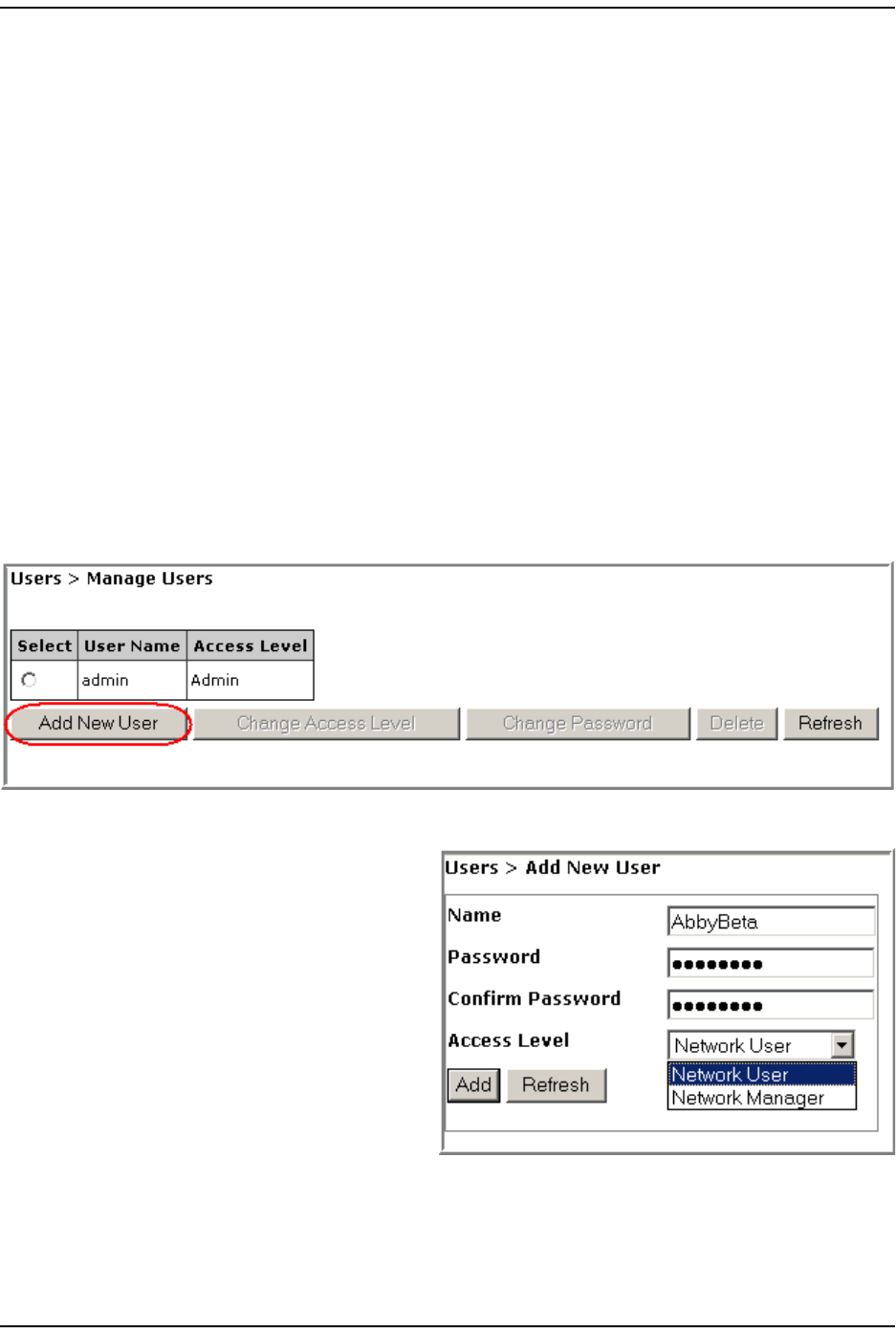
User s
FlexWave Prism Elem ent Managem ent Syst em 7.1 User Manual Page 205
ADCP- 77- 177 • I ssue 1 • July 2011 © 2011 ADC Telecom m unicat ions, I nc.
MANAGE USERS PAGE
The Manage Users page allows you t o:
•“ Add a New User” on page 205
•“ Change a User’s Access Level” on page 207
•“ Change a User Password” on page 208.
Add a New User
CAUTION! If Auto Complete (that is, remember username/password) is turned on in your web
browser, when you add a new user, the browser automatically fills in Prism user names
and passwords with the saved information. To avoid this, disable Auto Complete in your
browser.
1To access the Manage Users page, in t he Syst em Menu bar, click Users > Manage
Users.
2I n t he Manage Users page, click Add New User.
3Do t he following in t he Add New User page:
aI n t he Name box, ent er a user
nam e, which m ust st art wit h
an alphabet ical charact er,
cont ain at least 5 characters
( alphanum eric or underscore
only), and cont ain no spaces.
bI n t he Password box, ent er a
password specific t o t his user.
The Password m ust contain at
least 6 alphanum eric or special
characters, and cannot be
em pty or contain spaces.
cI n t he Confirm Password box, enter t he exact sam e password as you entered
in t he Password box.
dI n t he Access Level m enu, select the access level for t his user. See
“ Underst anding FlexWave EMS User Accounts” on page 204.
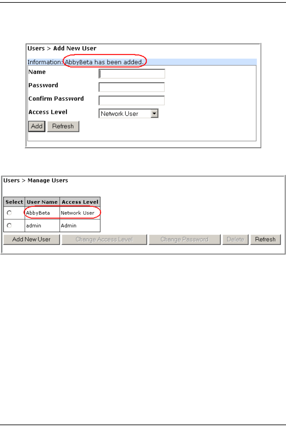
Manage Users Page
Page 206 FlexWave Prism Elem ent Managem ent System 7.1 User Manual
© 2011 ADC Telecommunications, Inc ADCP-77- 177 • I ssue 1 • July 2011
4Click Add.
The following m essage displays, list ing the new user by Name. Addit ionally, t he
Add New User fields are cleared so you can add ot her users as needed.
5I n t he Syst em Menu bar, click Users > Manage Users t o see an updat ed list of
users.
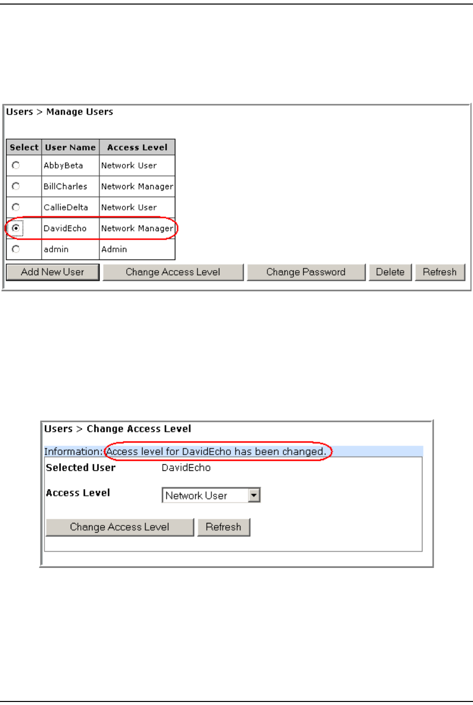
User s
FlexWave Prism Elem ent Managem ent Syst em 7.1 User Manual Page 207
ADCP- 77- 177 • I ssue 1 • July 2011 © 2011 ADC Telecom m unicat ions, I nc.
Change a User’s Access Level
1I n the Syst em Menu bar, click Users > Manage Users t o see a list of users.
2To change a user’s access, select the user in t he Select colum n, which activat es
the operational but tons.
3Click Change Access.
4Verify that t he nam e list ed for Selected User is the user whose access level you
want t o change.
5I n t he Change Access Level page, use t he Access Level m enu t o change t he access
level for t his user. For further inform at ion on access levels, see “ Underst anding
FlexWave EMS User Account s” on page 204.
6Click Change Access.
The Access Level for <username> is changed successfully m essage displays.
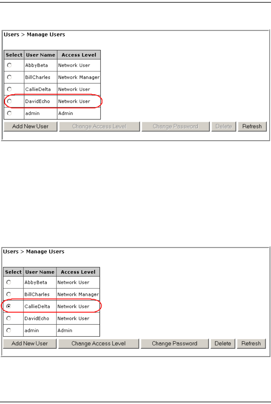
Manage Users Page
Page 208 FlexWave Prism Elem ent Managem ent System 7.1 User Manual
© 2011 ADC Telecommunications, Inc ADCP-77- 177 • I ssue 1 • July 2011
7I n t he Syst em Menu bar, click Users > Manage Users t o see an updat ed list of
users.
At this tim e the operat ional buttons, wit h the except ion of Add New User and
Refresh, will be disabled, as no user is select ed.
Change a User Password
NOTE: Only the admin user or a user with the Network Manager access level can change the
password of another user.
1I n the Syst em Menu bar, click Users > Manage Users t o see a list of users.
2To change a user’s password, select t he user in t he Select colum n, which
act ivat es the operat ional but t ons.
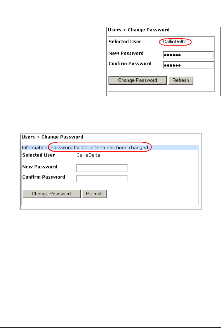
User s
FlexWave Prism Elem ent Managem ent Syst em 7.1 User Manual Page 209
ADCP- 77- 177 • I ssue 1 • July 2011 © 2011 ADC Telecom m unicat ions, I nc.
3Click Change Password.
4I n t he Change Password page, do t he following:
aVerify that the nam e list ed
for Selected User is for t he user
whose password you want t o
change.
bI n t he New Password box,
enter a new password for
this user. The Password
m ust cont ain at least 6
alphanum eric or special
characters, and cannot be
em pty or contain spaces.
cI n t he Confirm Password box,
ent er t he exact sam e password as you ent ered in t he New Password box.
5Click Change Password.
The Password changed successfully m essage displays.
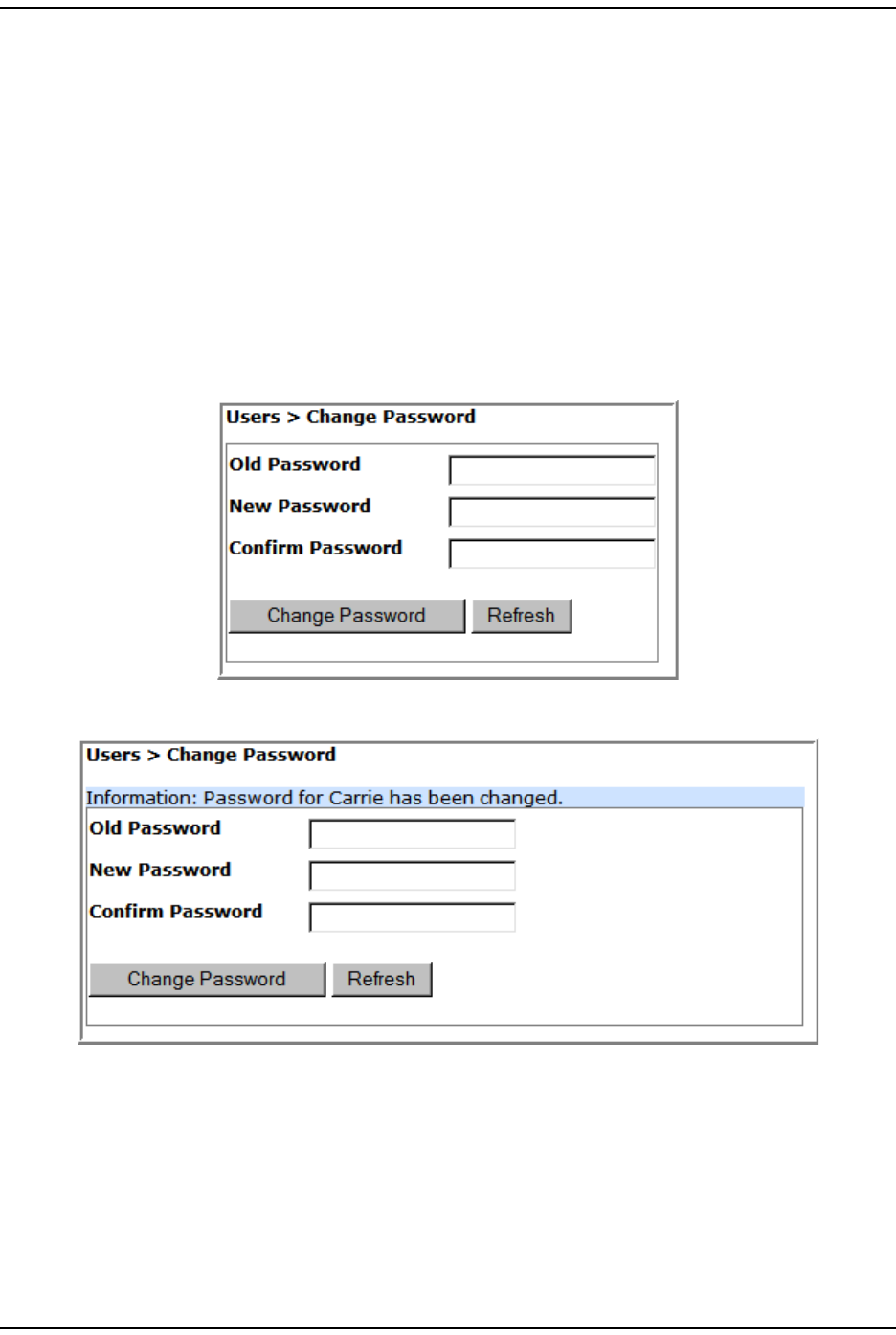
Change Your Personal Passw ord
Page 210 FlexWave Prism Elem ent Managem ent System 7.1 User Manual
© 2011 ADC Telecommunications, Inc ADCP-77- 177 • I ssue 1 • July 2011
CHANGE YOUR PERSONAL PASSWORD
1I n the Syst em Menu bar, click Users > Change Password.
2I n t he Change Password page, do t he following:
aI n t he Old Password box, ent er your exist ing password.
bI n t he New Password box, enter a new password for this user. The Password
m ust cont ain at least 6 alphanum eric or special charact ers, and cannot be
em pty or contain spaces.
cI n t he Confirm Password box, enter t he exact sam e password as you entered
in t he New Password box.
3Click Change Password.
The Password for <username> has been changed m essage displays.

User s
FlexWave Prism Elem ent Managem ent Syst em 7.1 User Manual Page 211
ADCP- 77- 177 • I ssue 1 • July 2011 © 2011 ADC Telecom m unicat ions, I nc.
RECOVERING A PASSWORD
I f a user changes his or her password and t hen forget s t he new password, the
adm in user needs t o recreat e an account for t he user.
I f the password is changed and then forgot t en for t he adm in user, the adm in
should cont act ADC for assist ance.
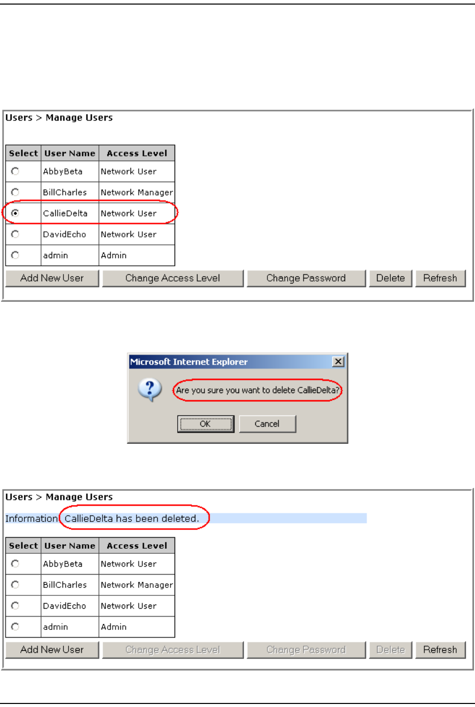
Delet e a User
Page 212 FlexWave Prism Elem ent Managem ent System 7.1 User Manual
© 2011 ADC Telecommunications, Inc ADCP-77- 177 • I ssue 1 • July 2011
DELETE A USER
1I n the Syst em Menu bar, click Users > Manage Users t o see a list of users.
2Select the user whose account is t o be delet ed in t he Select colum n, which
act ivat es the operat ional but t ons.
3Click Delete.
4I n t he confirm at ion dialog, which ident ifies t he user being delet ed, click OK.
The User deleted successfully m essage displays and t he Users t able is updat ed in
the Manage Users page.

FlexWave Prism Elem ent Managem ent Syst em 7.1 User Manual Page 213
ADCP- 77- 177 • I ssue 1 • July 2011 © 2011 ADC Telecommunications, Inc.
UPGRADING THE SYSTEM AND UNITS
Upload t he Upgrade Files ...................................................................................................... 214
Updat ing a Prism Syst em ...................................................................................................... 216
Com m it the Upgr ade ............................................................................................................ 219
Abort an Update .................................................................................................................. 220
Updat ing I ndividual Unit s ...................................................................................................... 221
Upgrading a Prism syst em or a unit wit hin a Prism system is a three- st ep process,
in which you do t he following:
1Upload t he upgrade file.
2Use t he upgrade file t o updat e t he syst em or unit .
3Com m it the updat e.
Topics Page
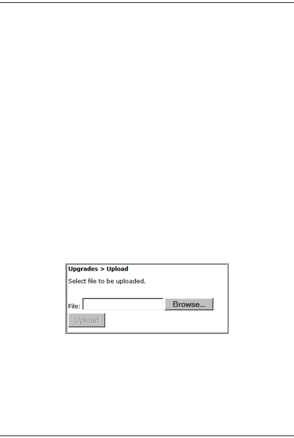
Upload the Upgrade Files
Page 214 FlexWave Prism Elem ent Managem ent System 7.1 User Manual
© 2011 ADC Telecommunications, Inc ADCP-77- 177 • I ssue 1 • July 2011
UPLOAD THE UPGRADE FILES
Use t he Upload page t o t ransfer the required upgrade files from a com puter or
laptop t o your Prism syst em or unit .
Each soft ware upgrade requires the following files t o go from one version t o the
next :
• upgrade.x-y.tar.gz.md5
• upgrade.x-y.tar.gz
where
•x ident ifies the version from which t he unit / syst em is being upgraded
•y ident ifies the version to which t he unit / system is being upgraded.
NOTE: Each upgrade file set is designed to upgrade a specific EMS release, which may be
updating the EMS GUI or unit firmware, or both. If you try to apply upgrade files to a
system/unit that is not running the EMS release for which the upgrade files are designed,
the update will abort when it runs its version check.
Do t he following t o upload t he required upgrade files:
1Cont act ADC t o obtain the appropriate upgrade files ( see “ Appendix C:
Cont act ing ADC/ TE Connect ivit y” on page 297).
2Verify that t here is sufficient space on the disk drive to accom m odat e t he
upgrade files t hat you need to upload.
3Save t he upgrade files to your com puter.
4To access the Upload page, in t he Syst em Menu bar, click Upgrades > Upload.
5Click Browse.
6I n t he Choose File dialog, navigat e t o where the upgrade *.tar.gz and *.tar.gz.md5
files are st ored.
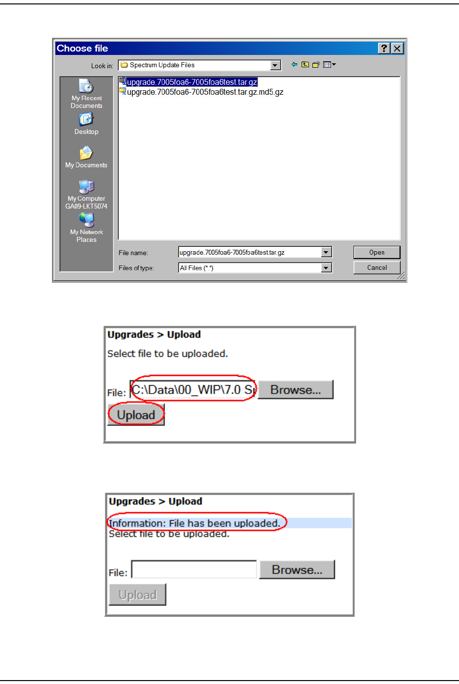
Upgrading t he Syst em and Unit s
FlexWave Prism Elem ent Managem ent Syst em 7.1 User Manual Page 215
ADCP- 77- 177 • I ssue 1 • July 2011 © 2011 ADC Telecom m unicat ions, I nc.
7Select the *.tar.gz file, and then click Open.
The Choose File dialog closes and t he nam e of the select ed file displays in t he
Upgrades > Upload page File box.
8Click Upload.
Wait for the File has been uploaded m essage t o display.

Updat ing a Pr ism System
Page 216 FlexWave Prism Elem ent Managem ent System 7.1 User Manual
© 2011 ADC Telecommunications, Inc ADCP-77- 177 • I ssue 1 • July 2011
9I n t he Upload page, Click Browse.
1 0 I n t he Choose File dialog, navigat e t o where the upgrade *.tar.gz and *.tar.gz.md5
files are st ored.
1 1 Select the *.tar.gz.md5 upgrade file, and t hen click Open.
1 2 The Choose File dialog closes and t he nam e of t he selected file displays in the
Upgrades > Upload page File box.
1 3 Click Upload.
Wait for the File has been uploaded m essage t o display.
UPDATING A PRISM SYSTEM
Follow this procedure t o updat e a FlexWave Prism syst em , or an individual unit
wit hin a FlexWave Prism syst em .
CAUTION! Do not make any configuration changes during an update.
CAUTION! This procedure takes the system selected for update temporarily offline (see estimates in
Table 25). Perform this procedure during normal maintenance window.
NOTE: To update an individual unit, see “Updating Individual Units” on page 221.
Do t he following t o update an FlexWave Prism system :
1Access t he Soft ware/ Firm ware report t o verify current syst em soft ware.
aI n the Syst em Menu bar, click System Information > Get Information.
The System Information > Get Information page opens.
bI n t he Type list , select Software/Firmware. ( This is t he default setting.)
Table 25. Estimated Time a System is Offline During an Upgrade
System Configuration Approximate Time Offline
(Minutes)
1 Host + 1 Remote Unit 7 - 11
1 Host + 2 Remote Units 10 - 18
1 Host + 3 Remote Units 15 - 27
1 Host + 4 Remote Units 21 - 37
1 Host + 5 Remote Units 28 - 48
1 Host + 6 Remote Units 37 - 61
1 Host + 7 Remote Units 48 - 76
1 Host + 8 Remote Units 60 - 92
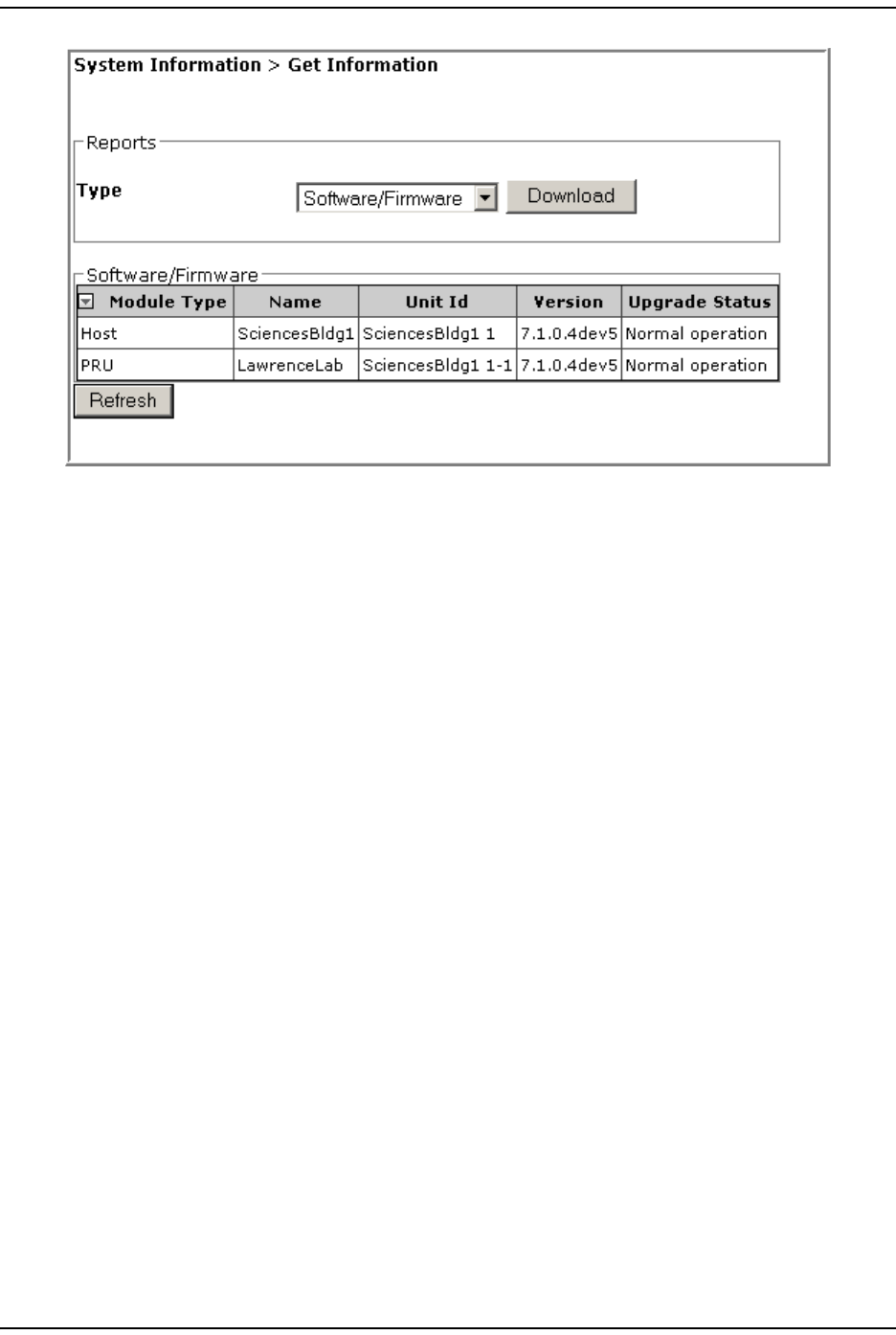
Upgrading t he Syst em and Unit s
FlexWave Prism Elem ent Managem ent Syst em 7.1 User Manual Page 217
ADCP- 77- 177 • I ssue 1 • July 2011 © 2011 ADC Telecom m unicat ions, I nc.
The Software/Firmware t able provides the following inform at ion:
•Module Type—type of unit ( Host, PRU, or URU).
•Name—user- assigned nam e for t he unit .
•Unit Id—ident ifies the unit wit hin the syst em ( see “ Unit I dent ification” on
page 43) .
•Version—version of inst alled soft ware/ firm ware.
•Upgrade Status—t he following st at es can be seen. However, wit h t he
except ion of Normal operation and Upgraded, the st at es occur very quickly
during t he corresponding action and are rarely viewed.
–Normal operation
–Upgrading
–Upgrading reboot
–Committing
–Aborting
–Recovering
– Upgraded
–NA ( analog units only) .
2Follow the steps in “ Upload t he Upgrade Files” on page 214 to upload t he
required upgrade files.
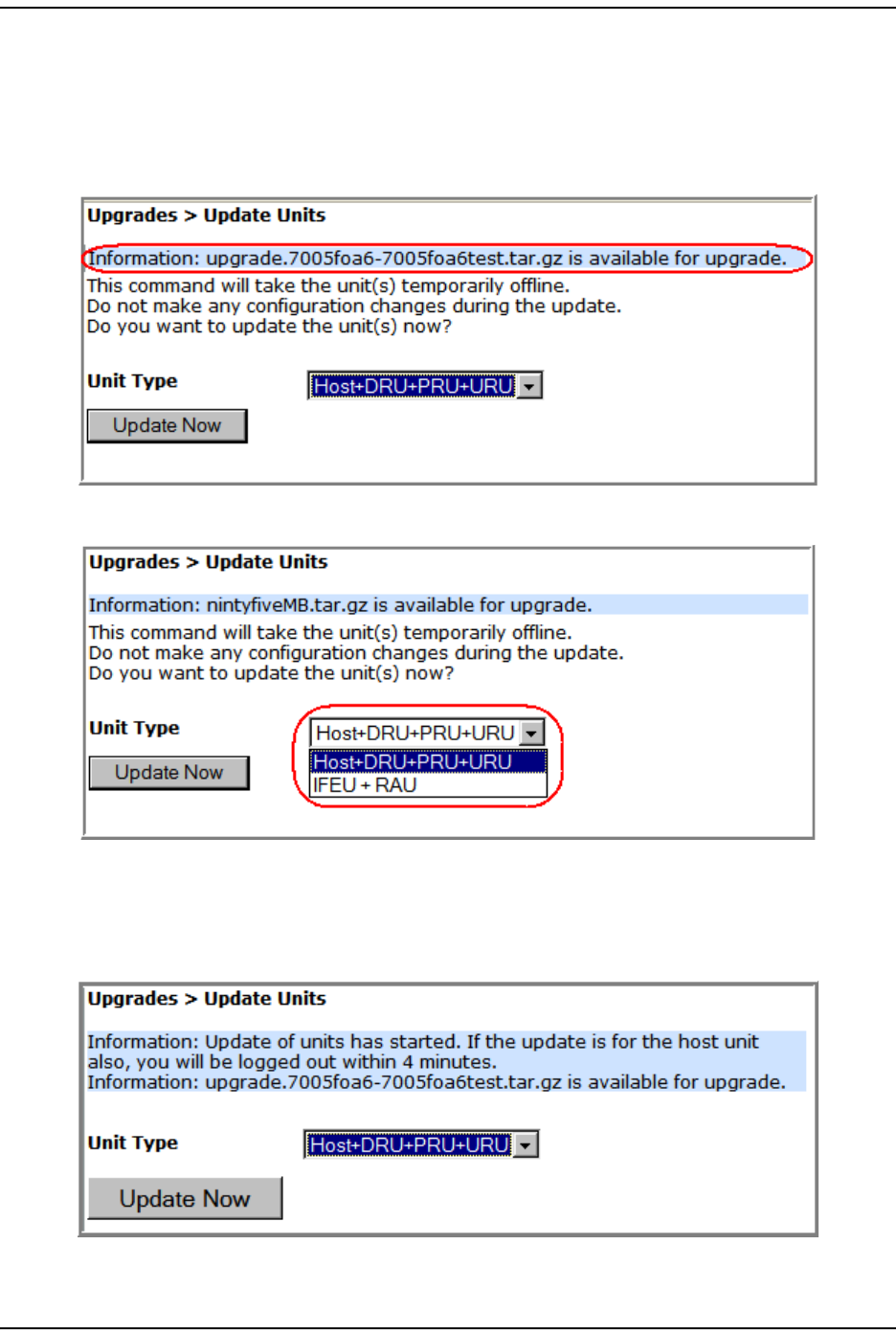
Updat ing a Pr ism System
Page 218 FlexWave Prism Elem ent Managem ent System 7.1 User Manual
© 2011 ADC Telecommunications, Inc ADCP-77- 177 • I ssue 1 • July 2011
3Update the Host and t he Rem ot e Unit(s) :
aI n the Syst em Menu bar, click Upgrades > Update Units.
I n t he Update Units page, you are not ified t hat the file t hat you uploaded in
“ Upload t he Upgrade Files” on page 214 is ready for use. I f an upgrade file
is not list ed, repeat t he steps in “ Upload t he Upgrade Files” on page 214.
bI n t he Select Unit Type list , select Host+DRU+PRU+URU.
NOTE: The IFEU + RAU option pertains to an InterReach Spectrum system only and is not
applicable to a Prism system. As such, do not select the IFEU + RAU option.
cClick Update Now. An inform ation m essage that t he updat e has st art ed
appears.
Wit hin four m inut es, t he EMS logs you off and t erm inat es t he EMS session.
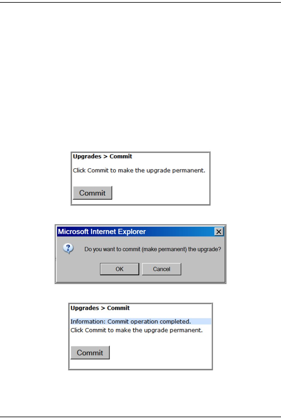
Upgrading t he Syst em and Unit s
FlexWave Prism Elem ent Managem ent Syst em 7.1 User Manual Page 219
ADCP- 77- 177 • I ssue 1 • July 2011 © 2011 ADC Telecom m unicat ions, I nc.
CAUTION! At this point, the system goes offline for the approximate time listed in Table 25 on
page 216.
dWait approxim at ely four m inutes, and t hen log back in to t he EMS to
com plete this procedure.
4Com plet e St ep 1 on page 216 t o verify the st atus of the Host / Rem ot e Unit ( s)
updat es.
COMMIT THE UPGRADE
NOTE: If you need to abort an update, go to“Abort an Update” on page 220.
1Com plet e t he st eps in “ Updat ing a Prism Syst em ” on page 216.
2I n the Syst em Menu bar, click Upgrades > Commit.
3I n t he Upgrades > Commit page, click Commit.
4I n t he confirm at ion window, click OK.
The syst em inform s you when the com m it operation has com pleted.
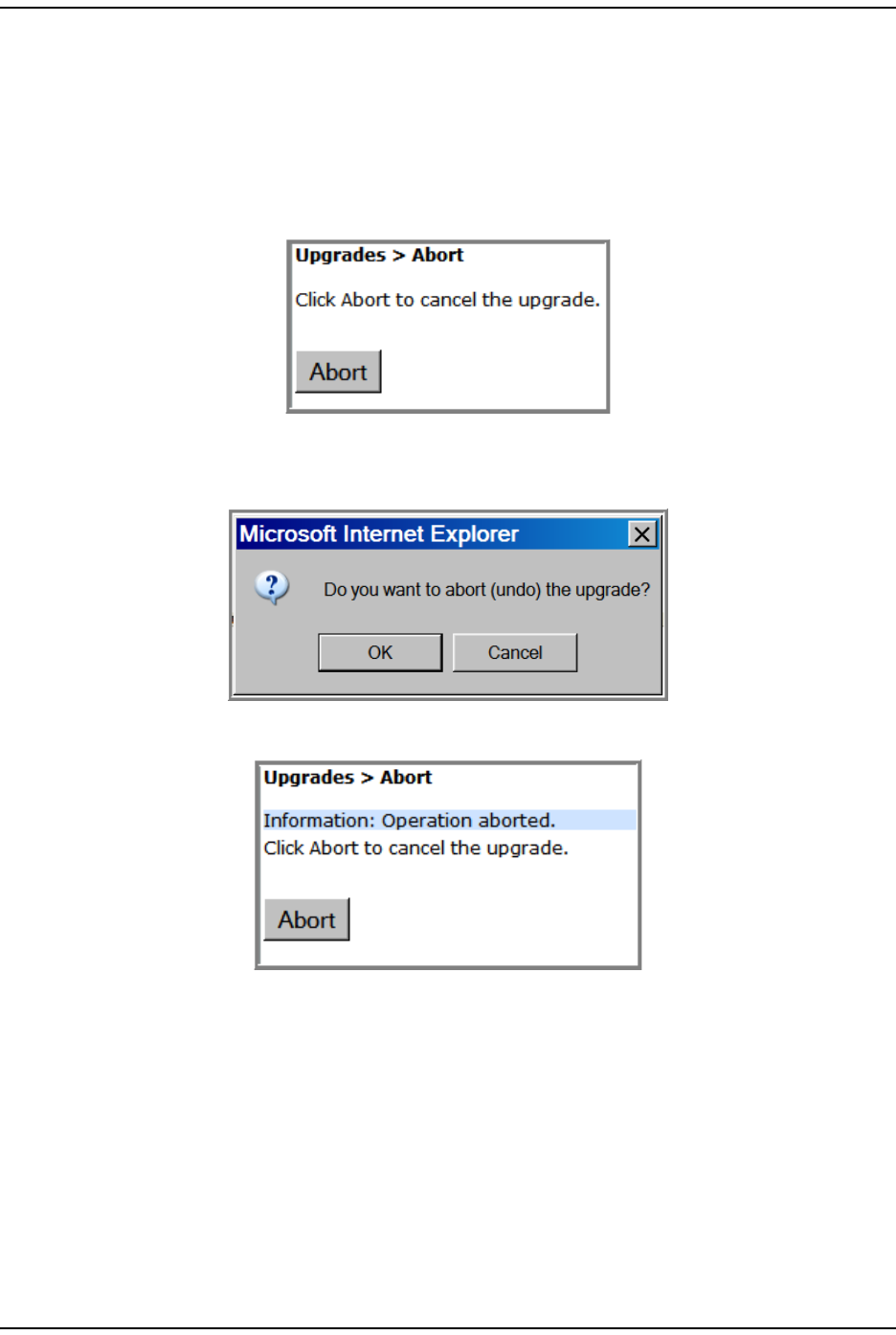
Abort an Updat e
Page 220 FlexWave Prism Elem ent Managem ent System 7.1 User Manual
© 2011 ADC Telecommunications, Inc ADCP-77- 177 • I ssue 1 • July 2011
ABORT AN UPDATE
An upgrade can be aborted, if necessary.
NOTE: If you want to commit an update, go to “Commit the Upgrade” on page 219.
1To access the Upgrades Abort page, in t he Syst em Menu bar, click Upgrades > Abort.
2Click Abort.
3I n t he confirm at ion window, click OK.
The syst em inform s you when the abort operat ion has com plet ed.
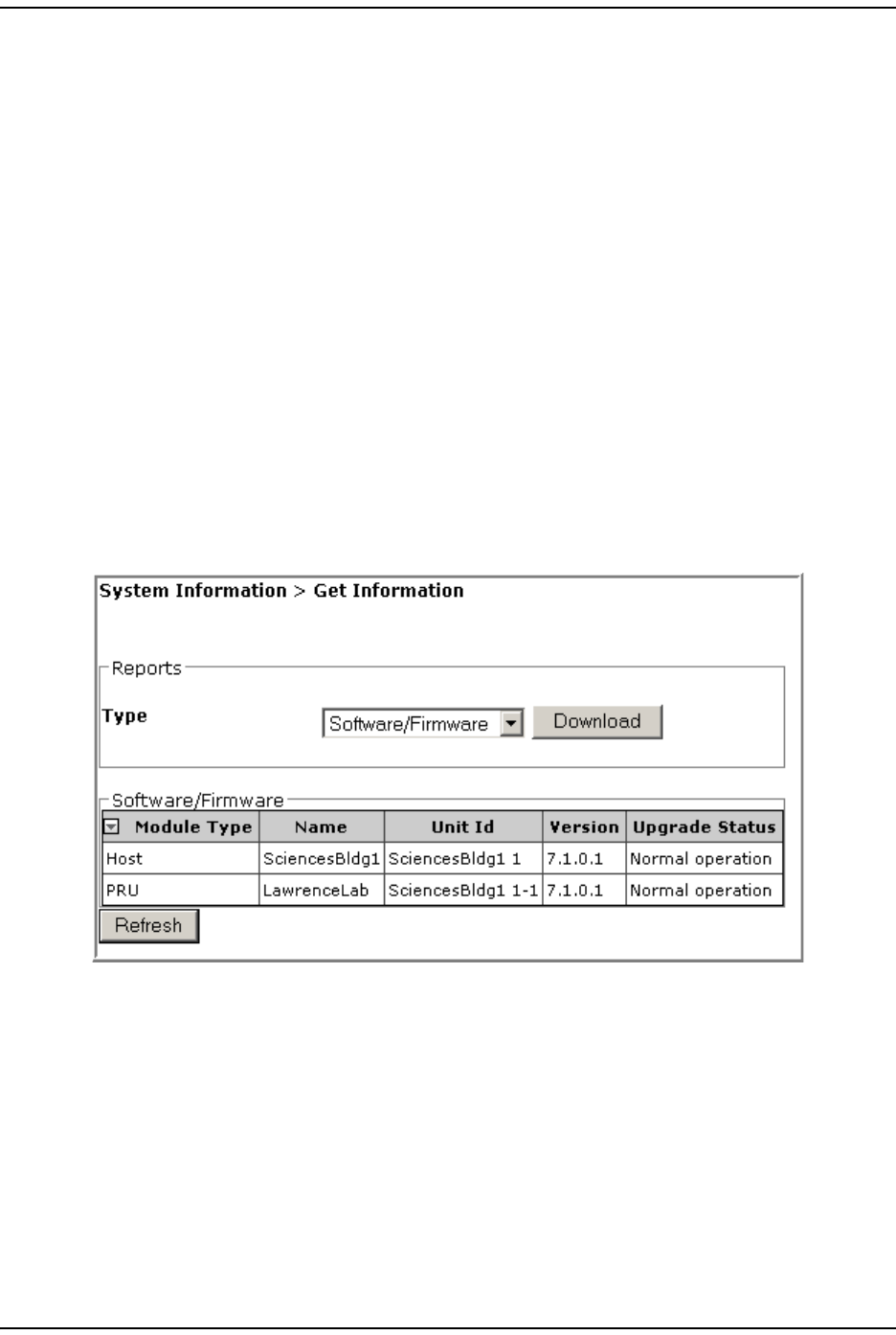
Upgrading t he Syst em and Unit s
FlexWave Prism Elem ent Managem ent Syst em 7.1 User Manual Page 221
ADCP- 77- 177 • I ssue 1 • July 2011 © 2011 ADC Telecom m unicat ions, I nc.
UPDATING INDIVIDUAL UNITS
Only perform a unit updat e on a unit when the unit is being added t o the syst em
as a new or replacem ent unit, and t he new unit requires a firm ware updat e t o
m at ch t he firm ware version of the ot her units wit hin t he syst em .
CAUTION! If this procedure is performed on a Host Unit, the Host is taken offline (see estimates in
Table 25 on page 216). Perform this procedure during normal maintenance time.
CAUTION! Do not make any configuration changes during an update.
NOTE: To update a Prism system, follow the steps in “Updating a Prism System” on page 216.
Com plet e t he following steps to updat e an individual Host , PRU, or URU:
1Access t he Soft ware/ Firm ware report t o verify current syst em soft ware.
aI n the Syst em Menu bar, click System Information > Get Information.
The System Information > Get Information page opens.
bI n t he Type list , select Software/Firmware. ( This is the default set t ing.)
For inform ation on t he Software/Firmware table, see “ Updat ing a Prism System ”.
2Follow t he steps in “Upload t he Upgrade Files” on page 214 to upload the
required updat e files.
3I n the Syst em Tree, click on t he icon of the unit t hat you want t o updat e.
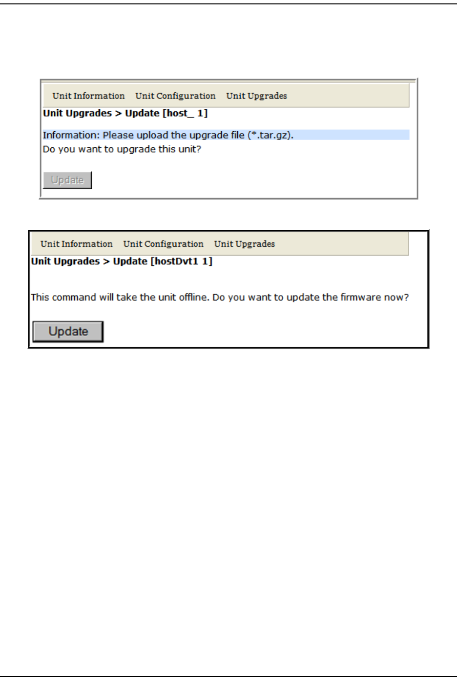
Updat ing I ndividual Unit s
Page 222 FlexWave Prism Elem ent Managem ent System 7.1 User Manual
© 2011 ADC Telecommunications, Inc ADCP-77- 177 • I ssue 1 • July 2011
4I n the Unit Menu bar, click Unit Upgrades, Upgrade.
NOTE: If you have not uploaded the required update files, the following page opens, and the
Update button is disabled. You cannot continue until the correct update files have been
loaded.
5Click Update.
Wit hin four m inut es, t he EMS logs you off and t erm inat es t he EMS session.
CAUTION! At this point, the system goes offline for the approximate time listed in Table 25 on
page 216.
6Wait approxim at ely four m inutes, and then log back in t o the EMS to com plet e
this procedure.
7Com plet e St ep 1 on page 216 t o verify the st atus of t he updat e. Do not m ove
forward to the next st ep unt il the UpGrade Status in the Soft ware/ Firm ware table
is listed as Upgraded.
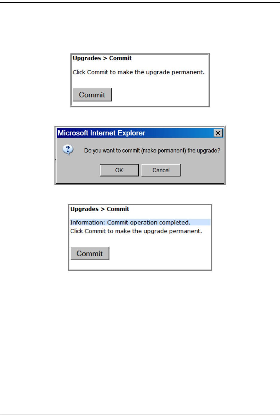
Upgrading t he Syst em and Unit s
FlexWave Prism Elem ent Managem ent Syst em 7.1 User Manual Page 223
ADCP- 77- 177 • I ssue 1 • July 2011 © 2011 ADC Telecom m unicat ions, I nc.
8Com m it the updat e t o t he unit. ( I f you need to abort an updat e, go t o “ Abort
an Update” on page 220.)
aI n the Syst em Menu bar, click Upgrades > Commit.
bI n t he Upgrades > Commit page, click Commit.
cI n t he confirm at ion window, click OK.
The syst em inform s you when the com m it operation has com pleted.
9Com plet e St ep 1 on page 216 to verify t he stat us of t he updat e.

Updat ing I ndividual Unit s
Page 224 FlexWave Prism Elem ent Managem ent System 7.1 User Manual
© 2011 ADC Telecommunications, Inc ADCP-77- 177 • I ssue 1 • July 2011
I nt ent ionally Blank Page

FlexWave Prism Elem ent Managem ent Syst em 7.1 User Manual Page 225
ADCP- 77- 177 • I ssue 1 • July 2011 © 2011 ADC Telecommunications, Inc.
SPECIAL FEATURES
Run Script ........................................................................................................................... 226
Run Com m and .....................................................................................................................226
Configure Feature ................................................................................................................ 227
This sect ion describes special features of the Prism EMS.
NOTE: Some of the features in this section are for use by ADC only.
Topics Page
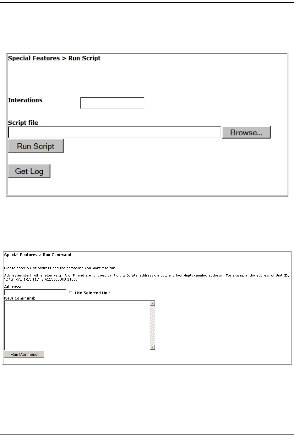
Run Scr ipt
Page 226 FlexWave Prism Elem ent Managem ent System 7.1 User Manual
© 2011 ADC Telecommunications, Inc ADCP-77- 177 • I ssue 1 • July 2011
RUN SCRIPT
The Run Script page, accessed via Special Features > Run Script, is not applicable t o a
Prism syst em and should not be used.
RUN COMMAND
The Run Command page, accessed via Special Features > Run Command, is not applicable
to a Prism syst em and should not be used.
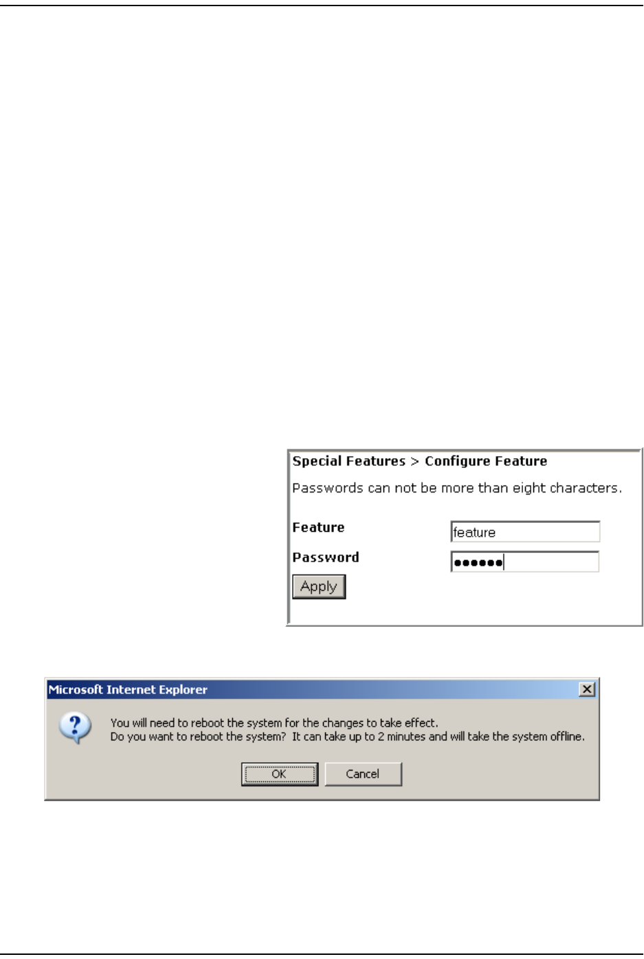
Special Feat ures
FlexWave Prism Elem ent Managem ent Syst em 7.1 User Manual Page 227
ADCP- 77- 177 • I ssue 1 • July 2011 © 2011 ADC Telecom m unicat ions, I nc.
CONFIGURE FEATURE
CAUTION! This procedure requires a system reboot. The system configuration is stored on the Host.
Rebooting the Host therefore results in a loss of RF for the Host and connected Remote
Units until the Host comes back up. Depending on the system configuration, it can take 5
to 20 minutes before management communication is restored.
CAUTION! Host configuration will not persist across a Configure Feature Reboot—all settings will
revert to factory default. You will need to reconfigure the Prism system after the system
reboots.
CAUTION! The current EMS session will close and you will need to log back in to the EMS after the
Host reboot has completed.
1Docum ent all configuration data, as set tings will have to be re- ent ered. To
record t he current configuration:
aFollow the procedures in “ Viewing t he All Report ” on page 112 to access t he
syst em configurat ion reports.
bFollow the procedures in “ Downloading a Report ” on page 113 t o download
the syst em configuration report s t o a hard drive.
2To access the Configure Feature page, in the Syst em Menu bar, click Special Features
> Configure Feature.
3I n t he Feature box, ent er the
code for the feature.
4I n t he Password box, enter t he
password that enables the
feat ur e.
5Click Apply.
6I n t he confirm at ion dialog, click OK.
7Log back in to the EMS once t he login window displays.
8Follow the st eps in “ I nit ial FlexWave Prism Syst em Set up” on page 55 t o
reconfigure t he Prism syst em , using the set tings recorded in St ep 1 on
page 227.

Configure Feat ure
Page 228 FlexWave Prism Elem ent Managem ent System 7.1 User Manual
© 2011 ADC Telecommunications, Inc ADCP-77- 177 • I ssue 1 • July 2011
I nt ent ionally Blank Page

FlexWave Prism Elem ent Managem ent Syst em 7.1 User Manual Page 229
ADCP- 77- 177 • I ssue 1 • July 2011 © 2011 ADC Telecommunications, Inc.
USING AN SNMP INTERFACE
SNMP Overview ...................................................................................................................230
Working wit h Prism MI B Files................................................................................................. 231
Accessing Prism MI Bs...................................................................................................... 233
Syst em Dat e and Tim e MI B Form at ................................................................................... 234
Band Types ................................................................................................................... 235
Prism MI B Obj ect s................................................................................................................ 236
Param eters in ADC- FLEXWAVE- URH-MI B ........................................................................... 237
Syst em - Level Param eters .......................................................................................... 237
Host Unit Param eters ................................................................................................ 239
Host Param eters.................................................................................................. 239
Host SeRF Card Param eters .................................................................................. 240
Host SeRF Optics Param et ers ................................................................................ 243
Host SeRF ENET Swit ch Param et ers ....................................................................... 245
Host SeRF FPGA Param eters ................................................................................. 247
Host List of Rem ot es Param et ers ........................................................................... 247
Host DART Module Param et er s .............................................................................. 248
Host Syst em Card Param et ers ............................................................................... 252
Rem ot e Unit Param eters ............................................................................................ 254
Rem ot e Param eters ............................................................................................. 254
Prism Rem ot e Syst em Card................................................................................... 256
Prism Rem ot e SeRF General.................................................................................. 257
Prism Rem ot e SeRF Opt ics.................................................................................... 260
Prism Rem ot e SeRF ENET Swit ch ........................................................................... 262
Prism Rem ot e SeRF FPGA ..................................................................................... 264
Prism Rem ot e DART............................................................................................. 264
Prism Rem ot e LPA ............................................................................................... 270
Prism Rem ot e Power Det ect or ............................................................................... 272
Prism Rem ot e LNA/ Duplexer ................................................................................. 273
Prism Rem ot e RDI Card ........................................................................................ 274
Prism Rem ot e RSI Car d ........................................................................................ 275
Com m on Managed Obj ect s ......................................................................................... 276
Prism DART Mapping ............................................................................................ 276
Schedule Syst em Link Test ................................................................................... 278
SNMP Set tings .................................................................................................... 279
Regist er SNMP Trap Manager ................................................................................ 280
Geographic Locations ................................................................................................ 281
GEO Obj ect s ....................................................................................................... 281
GEO Table Obj ect s............................................................................................... 282
Managed Obj ect s for Traps ......................................................................................... 283
Prism I nput Cont act Alarm Managem ent Table......................................................... 283
Syst em Act ive Alarm Table ................................................................................... 284
Alarm Managem ent Table ..................................................................................... 287
Alarm Enable Table .............................................................................................. 288
St atic Alarm s Table.............................................................................................. 288
Working wit h SNMP Traps ..................................................................................................... 290
View the Traps ............................................................................................................... 290
Managing Traps.............................................................................................................. 291
Dat e and Tim e Stam ps in Tr aps ........................................................................................ 292
Variable Bindings............................................................................................................ 293
Topics Page
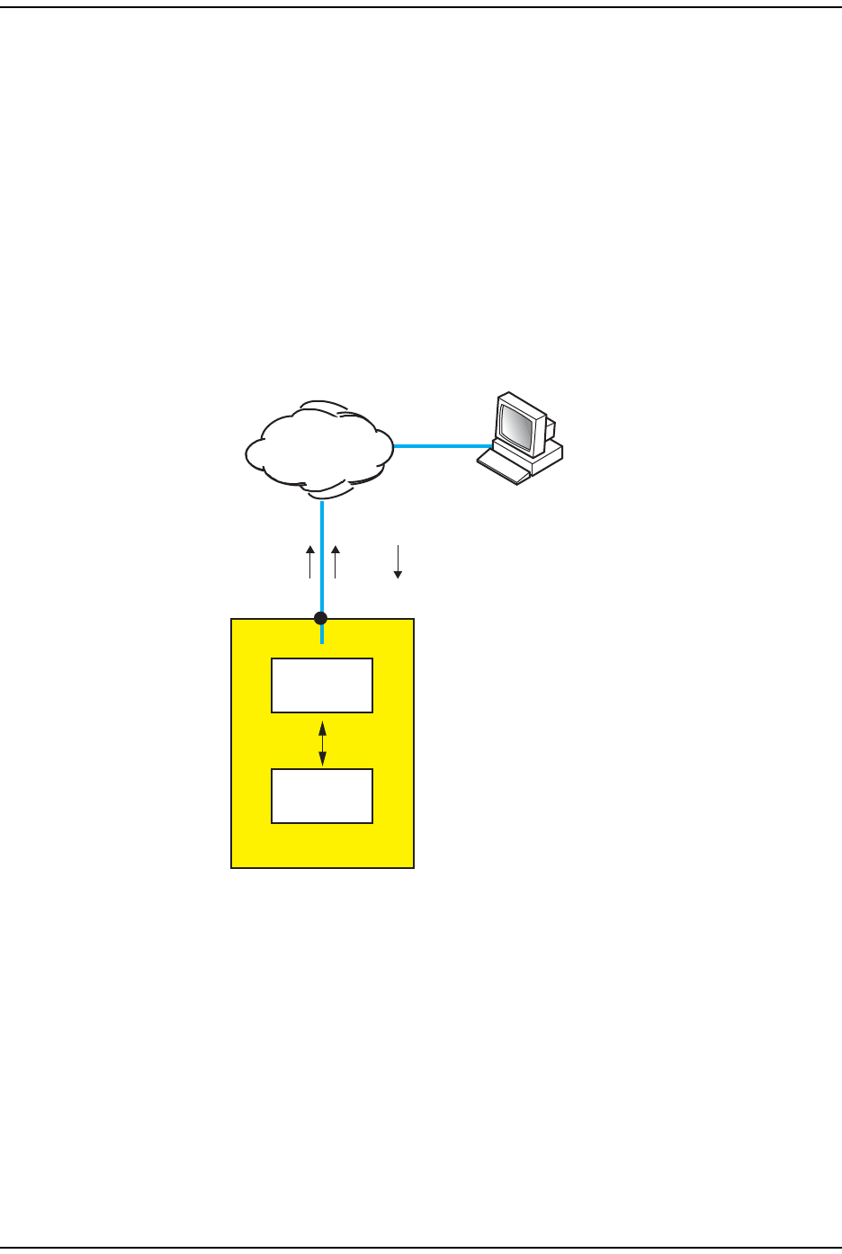
SNMP Overview
Page 230 FlexWave Prism Elem ent Managem ent System 7.1 User Manual
© 2011 ADC Telecommunications, Inc ADCP-77- 177 • I ssue 1 • July 2011
SNMP OVERVIEW
SNMP ( Sim ple Net work Managem ent Protocol) is an international st andard for
rem ot e control of online devices. A t ypical scenario involves t he devices being
cont rolled, rem ot e com puters ( called m anagers) that can cont rol them , a network
connect ion, and SNMP soft ware. The SNMP software includes SNMP m anager
soft ware on cont rolling com put ers, SNMP agent soft ware on m anaged devices,
and one or m ore MI Bs used by the SNMP m anagers for each cont rolled device. I n
som e cases, SNMP proxy agent software is run on an int erm ediate device t o
access a m anaged device t hat would not ot herwise be directly accessible.
The Prism syst em SNMP int erface, shown schem at ically in Figure 27 allows a
rem ot e user using an SNMP m anager t o access t he sam e dat abase as accessed by
the st andard EMS interface.
Figure 27. SNMP and a Prism System
IP
IP
Web
GET/SETTRAP
Windows 2000 or Windows XP
computer running
Internet Explorer or Mozilla
and/or SNMP Manager
Database
EMS
INTERNAL
Network port
Host Unit
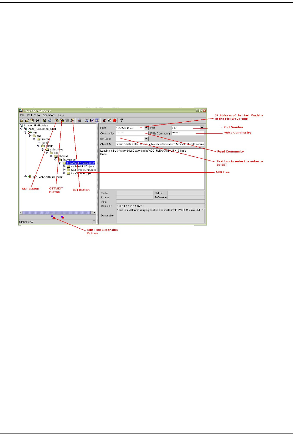
Using an SNMP I nt erface
FlexWave Prism Elem ent Managem ent Syst em 7.1 User Manual Page 231
ADCP- 77- 177 • I ssue 1 • July 2011 © 2011 ADC Telecom m unicat ions, I nc.
WORKING WITH PRISM MIB FILES
NOTE: Examples shown in this chapter use a browser from AdventNet or iReasoning. Procedural
details may vary with another browser, but the basic steps are the same.
NOTE: In the Prism system, the database accessed through the SNMP interface is the same
database as used by the EMS graphical user interface. There is therefore a similarity
between MIB objects and the parameters displayed in the EMS Web pages.
Figure 28 shows t he features of a t ypical MI B browser.
Figure 28. Typical MIB Browser
As m entioned earlier, a MI B is a database specificat ion cont aining definitions and
organizat ion of inform at ion. The database consist s of tables of obj ect s used t o
exchange inform ation between a m anager and agent . Dat abase inform ation is
exchanged using the following basic operat ions:
•GET—obt ains an obj ect value from t he dat abase.
•SET—set s t he value of an obj ect in the database.
•GET-NEXT—get s the next it em in the database, be it t he next t ype of obj ect or
the next obj ect of t he specified t ype. This is especially useful for discovering
the presence of ent ries in dynam ic t ables.
•GET-BULK—requests m ultiple item s in one m essage.
•TRAP/NOTIFICATION—sends an alarm in which a response can be sent by a
m anager t o an agent confirm ing receipt of t he alarm .
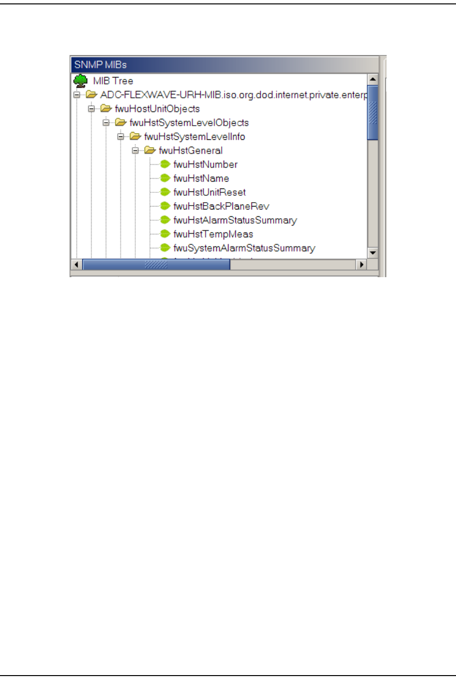
Wor king wit h Prism MI B Files
Page 232 FlexWave Prism Elem ent Managem ent System 7.1 User Manual
© 2011 ADC Telecommunications, Inc ADCP-77- 177 • I ssue 1 • July 2011
I n a m anager browser, a MI B looks like t he EMS System Tree’s hierarchy of folders
and files, as shown in Figure 29.
Figure 29. Prism MIB Tree
MI B it em s are arranged in a hierarchy of groups, like a hierarchy of folders. Known
OI Ds specify scalars ( obj ect s) . MI B obj ects are arranged in groups and t ables. To
be specified com plet ely, t able entries require one or m ore row indices. Each set of
obj ect s (wit hin a single folder) represents one such group or table. An obj ect
m arked wit h a key sym bol indicates that view is t he key value for t hat table.
The Prism MI B is defined by t hree files:
•ADC-FWU-URH-TC-MIB.mib
•ADC-FWU-IRS-TC-MIB.mib
•ADC-FLEXWAVE-URH.mib
The MI B can be found on t he SeRF I I card in the Host in /usr/local/fwu/mibs.
“ Prism MI B Obj ect s” on page 236 list s object s t hat m ay be accessed for GET/SET
operations and t raps/ not ificat ions that are sent t o SNMP m anagers regist ered t o
receive t hem whenever t he respective fault condit ion occurs.
NOTE: TRAPS/NOTIFICATIONS are listed with the corresponding EMS alarm in
“Troubleshooting Alarms” on page 185.
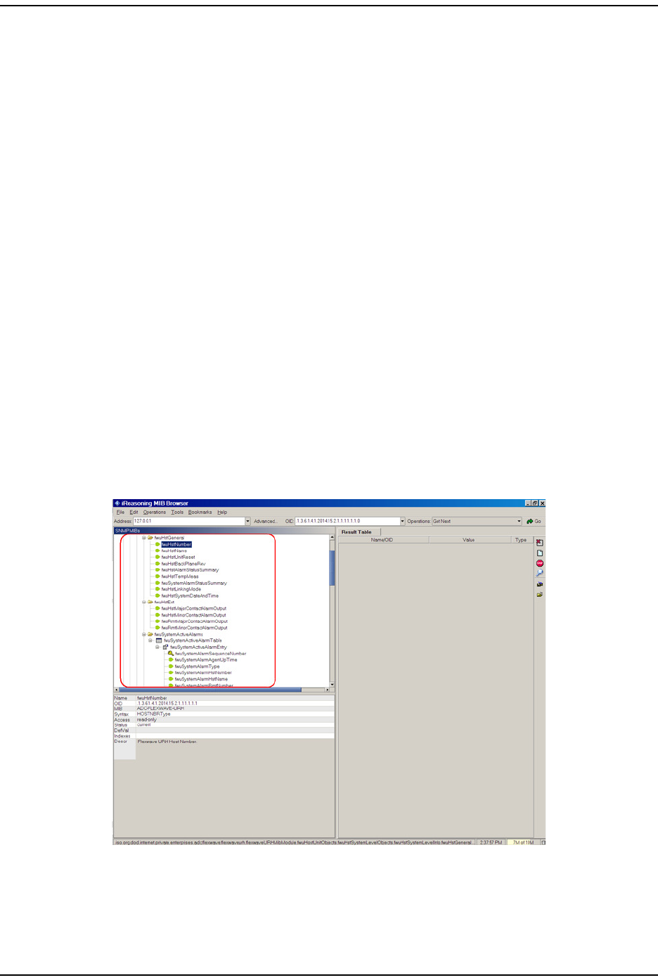
Using an SNMP I nt erface
FlexWave Prism Elem ent Managem ent Syst em 7.1 User Manual Page 233
ADCP- 77- 177 • I ssue 1 • July 2011 © 2011 ADC Telecom m unicat ions, I nc.
Accessing Prism MIBs
The Prism Agent MI B can be accessed using any SNMP m anager wit h an act ive
net work connect ion. The I P address of t he Host m ust be known and ent ered in t he
MI B browser.
1On t he m anager com puter, open t he MI B Browser.
2Load t he MI B files in the following order:
aADC-FWU-URH-TC-MIB.mib
bADC-FWU-IRS-TC-MIB.mib
cADC-FLEXWAVE-URH.mib
3Ent er t he I P address of t he Host of t he Prism syst em in t he t ext box provided
next to Host.
4Enter the Port number as 161.
NOTE: If you are upgrading from a previous release, note the change in the SNMP Port number.
In previous releases, the SNMP Port number was 8001. It is now 161.
5Enter the Read Community as public and Write Community as private.
6Set Timeout t o 15 seconds.
7For SNMP version v2c and v3, set Maximum Repetitions t o 10 or less.
8To see an overview t he MI B cont ent , expand t he MI B t ree, as shown below.

Wor king wit h Prism MI B Files
Page 234 FlexWave Prism Elem ent Managem ent System 7.1 User Manual
© 2011 ADC Telecommunications, Inc ADCP-77- 177 • I ssue 1 • July 2011
System Date and Time MIB Format
fwuHstSystemDateandTime allows you t o set the syst em dat e and tim e, where the
input is as follows:
YYYY-MM-DD,HH:MM:SS.D (24-Hour Time Format)
where fields are required ( none are opt ional) and indicate the following in 24- Hour
tim e form at.
•YYYY—Year
•MM—Month
•DD—dat e
•HH—Hour
•MM—Min ut e
•SS—Seconds
You can input the m ont h, dat e, hour, m inutes, seconds, and deci seconds as a
single digit or as a double digit ( t hat is, prefixed wit h 0) .
The support ed dat e and t im e range is from 1970-01-01,00:00:00 t o
2037-12-31,23:59:59.
The out put for m ont h, dat e, hour, m inutes, and seconds will always be in double
digit form at (prefixed wit h 0) . The out put for deci seconds will always be single
digit .
For exam ple, t he output of 2009-01-02,03:04:05 can be result ant from eit her of t he
following input s:
•I nput 1—2009-01-02,03:04:05
•I nput 2—2009-1-2,3:4:5

Using an SNMP I nt erface
FlexWave Prism Elem ent Managem ent Syst em 7.1 User Manual Page 235
ADCP- 77- 177 • I ssue 1 • July 2011 © 2011 ADC Telecom m unicat ions, I nc.
Band Types
Table 26 list s the band t ypes for Host RF DARTs, and Table 27 on page 236 list s
the band types for Rem ote I F DARTs.
Table 26. MIB Band Types—Host RF DARTS
MID Value Band Type
-1 undefined
1Classic850
2Classic1900
3ClassicSMR800
4ClassicSMR900
5ClassicAws2100
6Classic1800
200 SingleSuperPcs1900
201 SingleSuper1800
202 SingleSuperUmts2100
203 SingleSuperAws2100
8SuperPcs1900
10 SuperUmts2100
11 SuperAws2100
12 SuperEgsm900
13 SuperLowerAbc700
14 SuperUpperC700
205 SingleSuperLowerAbc700
206 SingleSuperUpperC700

Prism MI B Obj ect s
Page 236 FlexWave Prism Elem ent Managem ent System 7.1 User Manual
© 2011 ADC Telecommunications, Inc ADCP-77- 177 • I ssue 1 • July 2011
PRISM MIB OBJECTS
Obj ect s in the Prism Agent MI B divide into t wo t ypes: GET/SET object s and
Trap/ Notificat ion obj ect s.
For each GET and SET obj ect , t here is an SNMP synt ax, which is a range of values
defined in t he MI B file. These values are what can be ent ered in a SET com m and
and ret urned in a GET com m and.
The following sect ions list all MI B obj ect s wit hin t he Prism Agent MI B. Obj ect s that
are available for SET com m ands are also available for GET com m ands.
Table 27. MIB Band Types—Remote IF DARTS
MID Value Band Type
15 SuperIf850
16 SuperIfPcs1900
17 SuperIfSmr800
18 SuperIfSmr900
19 SuperIf1800
21 SuperIfAws2100
23 SuperIfPath1LowerAbc700
24 SuperIfPath1UpperC700
25 SuperIfPath2LowerAbc700
26 SuperIfPath2UpperC700
207 SingleSuperIf850
208 SingleSuperIfPcs1900
209 SingleSuperIfSmr800
210 SingleSuperIfSmr900
211 SingleSuperIf1800
213 SingleSuperIfAws2100
215 SingleSuperIfPath1LowerAbc700
216 SingleSuperIfPath1UpperC700
217 SingleSuperIfPath2LowerAbc700
218 SingleSuperIfPath2UpperC700

Using an SNMP I nt erface
FlexWave Prism Elem ent Managem ent Syst em 7.1 User Manual Page 237
ADCP- 77- 177 • I ssue 1 • July 2011 © 2011 ADC Telecom m unicat ions, I nc.
Parameters in ADC-FLEXWAVE-URH-MIB
System-Level Parameters
Syst em Dat e a nd Tim e
SNMP MIB: fwuHstSystemDateAndTime
Description: The dat e and tim e set t ings on t he system
Values: 1970-01- 01,00: 00: 00 to 2037-12-31,23: 59: 59; see “ Syst em Date
and Tim e MI B Form at” on page 234
Default: Syst em t im e
Syntax: Dat eAndTim e
Access Level: Oct et String
Syst em Ala rm Ack now ledge
SNMP MIB: fwuSystemAlarmAck
Description: Acknowledges all or individual alarm s
Values: 0 = Acknowledge all alarm s
Great er t hen 0, I d of t he alarm to be acknowledged
Syntax: I nteger32
Access Level: Read- Writ e
Syst em Ala rm Level
SNMP MIB: fwuAlarmLevel
Description: Alarm level of syst em
Syntax: Alarm Type
Access Level: Read- Writ e
Syst em Te st On Pow e r Up
SNMP MIB: fwuPwrUpLinkTest
Description: Syst em / Link Test on Power Up (Link Test )
Values: 1 = Enable
0 = Disable
Default: 0
Syntax: Unsigned32
Access Level: Read- Writ e

Prism MI B Obj ect s
Page 238 FlexWave Prism Elem ent Managem ent System 7.1 User Manual
© 2011 ADC Telecommunications, Inc ADCP-77- 177 • I ssue 1 • July 2011
DART Band Type for Syst em Test User Com m ande d
SNMP MIB: fwuUserCommLinkTestDartBandType
Description: Band t ype ( t he RF DART type) of select ed unit s
Values: See “ Band Types” on page 235.
Default: 0
Syntax: BandType
Access Level: Read- Writ e
DART I D for Syst e m Test Use r Com m a nde d
SNMP MIB: fwuUserCommLinkTestDartId
Description: I d of a particular DART
Values: 1 - 8
Syntax: I nteger32
Access Level: Read- Writ e
Syst em Ala rm St atus Sum m ary
SNMP MIB: fwuSystemAlarmStatusSummary
Description: Alarm St atus Sum m ary for ent ire syst em
Syntax: Alarm Type
Access Level: Read Only
Cle ar Syst em Configura t ion
SNMP MIB: fwuClearSysConfig
Description: Changing t he value from 0 to 1 clears the setting for the entire
set t ings on the syst em
Values: 0 = Disable
1= Enable
Default: 0
Syntax: I nteger32
Access Level: Read- Writ e
Last Run Tim e of Syst em / Link Test
SNMP MIB: fwuLinkTestLastRunTime
Description: Tim e when the Syst em / Link test was last run
Syntax: Dat eAndTim e
Access Level: Read Only

Using an SNMP I nt erface
FlexWave Prism Elem ent Managem ent Syst em 7.1 User Manual Page 239
ADCP- 77- 177 • I ssue 1 • July 2011 © 2011 ADC Telecom m unicat ions, I nc.
Host Unit Parameters
Host Parameters
Host N um ber
SNMP MIB: fwuHstNumber
Description: Num ber enum erating a Host
Values: A num ber great er than 0
Default: 1
Syntax: I nteger32
Access Level: Read Only
Host N a m e
SNMP MIB: fwuHstName
Description: User defined nam e of t he Host
Values: Alphanum eric Charact ers. Except as first character, t he underscore
( _) character is allowed. Must be 5 t o 40 charact ers in length, wit h
no spaces.
Default: Unknown_Host Nam e
Syntax: Display String
Access Level: Read- Writ e
Host Un it Reset
SNMP MIB: fwuHstUnitReset
Description: Reset s t he Host SeRF card when t he value is changed from 0 t o 1
Values: 0= norm al
1 = reset
Default: 0
Syntax: I nteger
Access Level: Read- Writ e
Host Back Plane Re vision
SNMP MIB: fwuHstBackPlaneRev
Description: Provides the back plane revision of t he Host ( Three pin Version
Num ber of the Chassis back plane)
Values: SI ZE ( 1…40)
Syntax: Oct al St ring
Access Level: Read Only

Prism MI B Obj ect s
Page 240 FlexWave Prism Elem ent Managem ent System 7.1 User Manual
© 2011 ADC Telecommunications, Inc ADCP-77- 177 • I ssue 1 • July 2011
Host Alarm St a t us Sum m a ry
SNMP MIB: fwuHstAlarmStatusSummary
Description: Alarm St atus Sum m ary for Host
Syntax: ALARM- TYPE
Access Level: Read Only
Te m pera t ure M ea sure m ent
SNMP MIB: fwuHstTempMeas
Description: Host syst em t em perat ure value in Celsius
Values: SI ZE ( 1…8)
Syntax: Oct al St ring
Access Level: Read Only
Linking Mode
SNMP MIB: fwuHstLinkingMode
Access Level: The DART Linking m ode on t he Syst em
Values: 2 = Manual
Default: 2
Syntax: I nteger
Access Level: Read- Writ e
Host SeRF Card Parameters
Linux Kernel Ve rsion
SNMP MIB: fwuHstSERFLinuxKernelVer
Description: Linux Kernel Version of the Host system
Syntax: Display String
Access Level: Read Only
Linu x Boot Loader Ver sion
SNMP MIB: fwuHstSERFLinuxBootLoaderVer
Description: Version Num ber of t he second st age boot loader
Syntax: Display String
Access Level: Read Only
Com pact Flash SW Ver sion
SNMP MIB: fwuHstSERFCompactFlashSWVer
Description: Com pact Flash Version of the Host syst em
Values: Form at of: aa.bb.cc.dd
where each of aa, bb, cc, dd m ust be bet ween 00 and 99
Syntax: Display String
Access Level: Read Only

Using an SNMP I nt erface
FlexWave Prism Elem ent Managem ent Syst em 7.1 User Manual Page 241
ADCP- 77- 177 • I ssue 1 • July 2011 © 2011 ADC Telecom m unicat ions, I nc.
PPC H W Mon it or SW Ver sion
SNMP MIB: fwuHstSERFPPCHWMonSWVer
Description: Soft ware Version of the hardware Monit or process running on t he
Host
Syntax: Display String
Access Level: Read Only
PPC Application Monit or SW Version
SNMP MIB: fwuHstSERFPPCAPPMonSWVer
Description: Soft ware Version of the Applicat ion Monit or process running on t he
Host
Syntax: Display String
Access Level: Read Only
SN M P Agent SW Version
SNMP MIB: fwuHstSERFPPCSNMPAgentSWVer
Description: Soft ware Version of the HTTP/ SNMP agent running on Host
Syntax: Display String
Access Level: Read Only
PPC M ate Monit or SW Version
SNMP MIB: fwuHstSERFPPCMATEMonSWVer
Description: Soft ware Version of the Mat e Monit or process running on the Host
Unit
Syntax: Display String
Access Level: Read Only
PPC EN ET Monit or SW Version
SNMP MIB: fwuHstSERFPPCENETMonSWVer
Description: Soft ware Version of the Ethernet Monitor process running on the Host
Unit
Syntax: Display String
Access Level: Read Only
PPC FPGA M onit or SW Version
SNMP MIB: fwuHstSERFPPCFPGAMonSWVer
Description: Version of FPGA Loaded on SeRF
Syntax: Display String
Access Level: Read Only

Prism MI B Obj ect s
Page 242 FlexWave Prism Elem ent Managem ent System 7.1 User Manual
© 2011 ADC Telecommunications, Inc ADCP-77- 177 • I ssue 1 • July 2011
Linux First St age Boot Loader Ve rsion
SNMP MIB: fwuHstSERFLinuxBootLoaderVer
Description: Boot Loader1 Version of the Host syst em
Syntax: Display String
Access Level: Read Only
Se RF FPGA Ver sion
SNMP MIB: fwuHstSERFFPGAVer
Description: Version of FPGA Loaded on SeRF
Syntax: Display String
Access Level: Read Only
RI ADC Pa rt N um ber
SNMP MIB: fwuHstSERFRIADCPartNumber
Description: Host SeRF I nvent ory - ADC Part Num ber
Syntax: Display String
Access Level: Read Only
RI Se rial N um ber
SNMP MIB: fwuHstSERFRISerialNumber
Description: Host SeRF I nventory - Serial Num ber
Syntax: Display String
Access Level: Read Only
RI Dat e Code
SNMP MIB: fwuHstSERFRIDateCode
Description: Host SeRF I nvent ory - Dat e Code
Syntax: Display String
Access Level: Read Only
Se RF RI H a rdw ar e Version
SNMP MIB: fwuHstSERFRIHWVer
Description: Host SeRF I nventory - Hardware Version
Syntax: Oct al St ring
Access Level: Read Only
Se RF RI H a rdw ar e Genera t ion
SNMP MIB: fwuHstSERFRIHWGen
Description: Host SeRF Hardware Generat ion
Values: 0 = First Generat ion
1 = Second Generat ion
Syntax: I nteger
Access Level: Read Only

Using an SNMP I nt erface
FlexWave Prism Elem ent Managem ent Syst em 7.1 User Manual Page 243
ADCP- 77- 177 • I ssue 1 • July 2011 © 2011 ADC Telecom m unicat ions, I nc.
pTh rea d Soft w a re Version
SNMP MIB: fwupThreadSoftwareVersion
Description: The version num ber of pThread process
Syntax: DisplaySt ring
Access Level: Read Only
Subagent Softw ar e Version
SNMP MIB: fwuSubagentSwVersion
Description: The version num ber of t he subagent
Syntax: DisplaySt ring
Access Level: Read Only
W e b Server Softw are Version
SNMP MIB: fwuWebServerSwVersion
Description: The version num ber of web server
Syntax: DisplaySt ring
Access Level: Read Only
Host SeRF Optics Parameters
SFP Num be r
SNMP MIB: fwuHstSERFOptSFPNumber
Description: SFP Num bers used as I ndex for Opt ical Port s
Values: 1 - 8
Syntax: I nt eger32
Access Level: Read Only
SFP Nam e
SNMP MIB: fwuHstSERFOptSFPName
Description: User defined SFP nam e - Opt ical Port Nam e
Values: Alphanum eric Charact ers. Except as first character, t he underscore
( _) charact er is allowed. Must be between 5 and 32 characters in
lengt h, wit h no spaces.
Default: UnknownSFPNam e
Syntax: Display String
Access Level: Read- Writ e
SFP Type
SNMP MIB: fwuHstSERFOptSFPType
Description: SFP Type - Opt ical Port Type
Syntax: Opt icsType
Access Level: Read Only

Prism MI B Obj ect s
Page 244 FlexWave Prism Elem ent Managem ent System 7.1 User Manual
© 2011 ADC Telecommunications, Inc ADCP-77- 177 • I ssue 1 • July 2011
SFP Transm ission Color
SNMP MIB: fwuHstSERFOptSFPTxColor
Description: SFP wavelengt h in nanom eter ( nm )
Syntax: I nteger32
Access Level: Read Only
FW D Launch Pow e r
SNMP MIB: fwuHstSERFOptFwdLaunchPowerMeas
Description: Value of Host Transm it m easured opt ical power in dBm
Syntax: DisplaySt ring
Access Level: Read Only
REV Re ceive Pow er
SNMP MIB: fwuHstSERFOptRevLaunchPowerMeas
Description: Value of Host Receive m easured opt ical power in dBm
Syntax: DisplaySt ring
Access Level: Read Only
Mate N am e
SNMP MIB: fwuHstSERFOptMateName
Description: Nam e of Host Mat es
Values: I nherit s the valid values from Host Nam e
Default: NA
Syntax: DisplaySt ring
Access Level: Read Only
Mate I D
SNMP MIB: fwuHstSERFOptMateId
Description: I D ( num erical) of com panion Rem ot e Unit
Values: See “ Unit I dentificat ion” on page 43
Syntax: NodeAddr1
Access Level: Read Only
Mat e SFP I D
SNMP MIB: fwuHstSERFOptMateSfpId
Description: Slot I D of t he SFP used at rem ot e end
Values: 1 - 8
Syntax: I nteger32
Access Level: Read Only

Using an SNMP I nt erface
FlexWave Prism Elem ent Managem ent Syst em 7.1 User Manual Page 245
ADCP- 77- 177 • I ssue 1 • July 2011 © 2011 ADC Telecom m unicat ions, I nc.
Host SeRF ENET Switch Parameters
Et her net Port N um ber
SNMP MIB: fwuHstSERFEthPortNumber
Description: An ident ifier for each Ethernet port
Values: 1…12
Syntax: Unsigned32
Access Level: Read Only
Et her net Port Type
SNMP MIB: fwuHstSERFEthPortType
Description: An ident ifier for t he type of Et hernet port
Syntax: Enet Type
Access Level: Read Only
Host SFP I D
SNMP MIB: fwuHstSERFEthPortSFPId
Description: I dent ifier of SFP to which t he Ethernet port connects
Values: 1…8
Syntax: I nteger32
Access Level: Read Only
Rx - by t e s
SNMP MIB: fwuHstSERFEthPortRxBytes
Description: Receive byt e count er
Syntax: Count er64
Access Level: Read Only
Rx - p ack e t s
SNMP MIB: fwuHstSERFEthPortRxPkts
Description: Receive packet count er
Syntax: Count er64
Access Level: Read Only
Rx- fsc- e rrors
SNMP MIB: fwuHstSERFEthPortRxFcsErrors
Description: Receive FCS error count er
Syntax: Count er64
Access Level: Read Only

Prism MI B Obj ect s
Page 246 FlexWave Prism Elem ent Managem ent System 7.1 User Manual
© 2011 ADC Telecommunications, Inc ADCP-77- 177 • I ssue 1 • July 2011
Re ce iv e- m ult ica st - pa ck et s
SNMP MIB: fwuHstSERFEthPortRxMulticastPkts
Description: Receive m ult icast packet counter
Syntax: Count er64
Access Level: Read Only
Re ce iv e- br oa dca st - pa ck e t s
SNMP MIB: fwuHstSERFEthPortRxBroadcastPkts
Description: Receive broadcast packet counter
Syntax: Count er64
Access Level: Read Only
Rx- fragm ent ed- fram es
SNMP MIB: fwuHstSERFEthPortRxFragmtdFrames
Description: Receive fragm ents count er
Syntax: Count er64
Access Level: Read Only
Rx- j abber- fram e s
SNMP MIB: fwuHstSERFEthPortRxJabbersFrames
Description: Receive jabber count er
Syntax: Count er64
Access Level: Read Only
Tx - byte- cou nt er
SNMP MIB: fwuHstSERFEthPortTxByteCounter
Description: Transm it byte counter
Syntax: Count er64
Access Level: Read Only
Tx - pa ck e t s
SNMP MIB: fwuHstSERFEthPortTxPkts
Description: Transm it packet counter
Syntax: Count er64
Access Level: Read Only
Tx - m ult ica st - pa ck e t s
SNMP MIB: fwuHstSERFEthPortTxMulticastPkts
Description: Transm it m ulticast packet counter
Syntax: Count er64
Access Level: Read Only

Using an SNMP I nt erface
FlexWave Prism Elem ent Managem ent Syst em 7.1 User Manual Page 247
ADCP- 77- 177 • I ssue 1 • July 2011 © 2011 ADC Telecom m unicat ions, I nc.
Tx - br oa dca st - p ack e t s
SNMP MIB: fwuHstSERFEthPortTxBroadcastPkts
Description: Transm it broadcast packet counter
Syntax: Count er64
Access Level: Read Only
Host SeRF FPGA Parameters
St a t u s
SNMP MIB: fwuHstSERFFPGAStatus
Description: Gives t he st atus if FPGA on SeRF Card
Values: 0 = PPC can t alk t o FPGA
1 = PPC cannot t alk t o FPGA
Default: 0
Syntax: I nteger
Access Level: Read Only
Host List of Remotes Parameters
Monit or I nde x
SNMP MIB: fwuHMmonIndex
Description: I ndex of t he Host m at e m onit or t able
Syntax: I nteger32
Access Level: Read Only
Rem ot e I D
SNMP MIB: fwuHMmonRmtID
Description: I D ( num erical) of com panion Rem ot e Unit
Values: See “ Unit I dentificat ion” on page 43
Syntax: NodeAddr1
Access Level: Read Only
Rem ot e I P Address
SNMP MIB: fwuHMmonRmtIPAddress
Description: List of I P addresses of connected Rem ot e Unit ( s)
Syntax: I pAddress
Access Level: Read Only

Prism MI B Obj ect s
Page 248 FlexWave Prism Elem ent Managem ent System 7.1 User Manual
© 2011 ADC Telecommunications, Inc ADCP-77- 177 • I ssue 1 • July 2011
Host DART Module Parameters
Card N um ber
SNMP MIB: fwuHstDARTNumber
Description: A unique ident ifier for each DART Module Obj ect
Values: Range 1 - 8
Syntax: I nteger
Access Level: Read Only
Card N am e
SNMP MIB: fwuHstDARTName
Description: A user defined nam e for each DART Module
Values: Alphanum eric Charact ers. Except as first character, t he underscore
( _) charact er is allowed. Must be between 5 and 32 charact ers in
lengt h, wit h no spaces.
Description: Unknown_DART
Syntax: Display String
Access Level: Read- Writ e
Ba nd Type
SNMP MIB: fwuHstDARTBandType
Description: Band t ype of Host DART Module
Values: See “ Band Types” on page 235.
Default: - 1
Syntax: BAND- TYPE
Access Level: Read Only
Pa ssband
SNMP MIB: fwuHstDARTPassBand
Description: Passband for t he select ed DART
Values: SI ZE ( 0…40)
Default: - 1
Syntax: OCTET STRI NG
Access Level: Read- Writ e
Ope rating Mode
SNMP MIB: fwuHstDARTOperatingMode
Description: Operat ing m ode of t he DART Module
Syntax: ModeType
Access Level: Read- Writ e

Using an SNMP I nt erface
FlexWave Prism Elem ent Managem ent Syst em 7.1 User Manual Page 249
ADCP- 77- 177 • I ssue 1 • July 2011 © 2011 ADC Telecom m unicat ions, I nc.
Diversit y St a t us
SNMP MIB: fwuHstDARTDiversityStatus
Description: Diversit y St atus of Host DART Module
Values: 0 = Non- diversit y
1 = Diversit y
Default: 0
Syntax: I nteger
Access Level: Read Only
Forw ard Gain
SNMP MIB: fwuHstDARTForwardGain
Description: Prim ary Gain of Host DART Module
Default: 0
Syntax: GainType
Access Level: Read- Writ e
Reverse Gain
SNMP MIB: fwuHstDARTReverseGain
Description: Prim ary Gain of Host DART Module
Values: 5…36, Unit s = dB, increm ents 1dB
Default: 0
Syntax: GainType
Access Level: Read- Writ e
FPGA St atus
SNMP MIB: fwuHstDARTFPGAStatus
Description: Host DART FPGA St at us; indicat es whet her the SeRF FPGA can talk
to t he DART FPGA
Values: 0 = SeRF FPGA can talk t o DART FPGA
1 = SeRF FPGA cannot talk t o DART FPGA
Default: 0
Syntax: I nteger
Access Level: Read Only
FPGA Pr ogram Ver sion
SNMP MIB: fwuHstDARTFPGAProgramVer
Description: FPGA version on t he DART Module
Syntax: Display String
Access Level: Read Only

Prism MI B Obj ect s
Page 250 FlexWave Prism Elem ent Managem ent System 7.1 User Manual
© 2011 ADC Telecommunications, Inc ADCP-77- 177 • I ssue 1 • July 2011
RI ADC Pa rt N um ber
SNMP MIB: fwuHstDARTRIADCPartNumber
Description: Host DART I nventory Dat a - ADC Part Num ber
Syntax: Display String
Access Level: Read Only
RI Se rial N um ber
SNMP MIB: fwuHstDARTRISerialNumber
Description: Host DART I nventory Dat a - Serial Num ber
Syntax: Display String
Access Level: Read Only
RI Dat e Code
SNMP MIB: fwuHstDARTRIDateCode
Description: Host DART I nventory Data Code
Syntax: Display String
Access Level: Read Only
DART RI H W Ve rsion
SNMP MIB: fwuHstDARTRIHWVer
Description: Host DART I nventory Dat a - HW Version
Syntax: Display String
Access Level: Read Only
Row St a t us
SNMP MIB: fwuHstDARTRowStatus
Description: The st atus of t his concept ual row
Syntax: Row St at u s
Access Level: Read- Cr eat e
Pe ak Avera ge I npu t Pow er Level 1
SNMP MIB: fwuHstDARTPeakInputPwrLvl1
Description: Peak Average input Power Level1. For Diversit y syst em s, this will be
NA.
Default: NA
Syntax: DisplaySt ring
Access Level: Read Only

Using an SNMP I nt erface
FlexWave Prism Elem ent Managem ent Syst em 7.1 User Manual Page 251
ADCP- 77- 177 • I ssue 1 • July 2011 © 2011 ADC Telecom m unicat ions, I nc.
Pe ak Avera ge I nput Pow er Level 2
SNMP MIB: fwuHstDARTPeakInputPwrLvl2
Description: Peak Average input Power level2. For Diversit y system s, this will be
NA.
Default: NA
Syntax: DisplaySt ring
Access Level: Read Only
Min Avera ge I nput Pow e r Le ve l 1
SNMP MIB: fwuHstDARTPeakAvgInputPwrLvl1
Description: Minim um Average I nput Power Level1. For Diversity syst em s, t his
will be NA.
Default: NA
Syntax: DisplaySt ring
Access Level: Read Only
Min Avera ge I nput Pow e r Le ve l 2
SNMP MIB: fwuHstDARTPeakAvgInputPwrLvl2
Description: Minim um Average I nput Power Level2. For Diversity syst em s, t his
will be NA.
Default: NA
Syntax: DisplaySt ring
Access Level: Read Only
Pe ak I nput Pow e r Level 1
SNMP MIB: fwuHstDARTMinAvgInputPwrLvl1
Description: Peak I nput Power Level2. For Diversit y system s, this will be NA.
Default: NA
Syntax: DisplaySt ring
Access Level: Read Only
Pe ak I nput Pow e r Level 2
SNMP MIB: fwuHstDARTMinAvgInputPwrLvl2
Description: Peak I nput Power Level2. For Diversit y system s, this will be NA.
Default: NA
Syntax: DisplaySt ring
Access Level: Read Only

Prism MI B Obj ect s
Page 252 FlexWave Prism Elem ent Managem ent System 7.1 User Manual
© 2011 ADC Telecommunications, Inc ADCP-77- 177 • I ssue 1 • July 2011
Pow e r Level M ode
SNMP MIB: fwuHstDARTInputPowerMode
Description: DART power level Mode
Values: 0 = snapshot
1 = m axHold
Default: 0
Syntax: I nteger
Access Level: Read- Writ e
Pow e r Level Max Hold Re set
SNMP MIB: fwuHstDARTPwrLevelMaxHoldReset
Description: Host DART I nput Power Level Max Hold Reset
Values: - 1 = Not Applicable
0 = Norm al
1 = Reset
Default: - 1
Syntax: I nteger
Access Level: Read- Writ e
Last M a x H old Reset Tim e
SNMP MIB: fwuHstDARTLastMaxHoldResetTime
Description: Dat e and Tim e of the last m axHold reset t im e of the Host DART
Syntax: Dat eAndTim e
Access Level: Read Only
I de ntify RF Sour ce
SNMP MIB: fwuHstDARTInputSrc
Description: I dent ifies whether t he connect ion is to BTS/ BDA
Values: 1 = BTS
2 = BDA
Default: 1
Syntax: I nteger
Access Level: Read- Writ e
Host System Card Parameters
RI ADC Pa rt N um ber
SNMP MIB: fwuHstSysCardRIADCPartNumber
Description: Rm t I nventory Dat a - ADC Part Num ber
Syntax: Display String
Access Level: Read Only

Using an SNMP I nt erface
FlexWave Prism Elem ent Managem ent Syst em 7.1 User Manual Page 253
ADCP- 77- 177 • I ssue 1 • July 2011 © 2011 ADC Telecom m unicat ions, I nc.
RI Se rial N um ber
SNMP MIB: fwuHstSysCardRISerialNumber
Description: Rm t I nventory Dat a - Serial Num ber
Syntax: Display String
Access Level: Read Only
RI Dat e Code
SNMP MIB: fwuHstSysCardRIDateCode
Description: Rm t I nventory Dat a - Dat e Code
Syntax: Display String
Access Level: Read Only
RI HW Version
SNMP MIB: fwuHstSysCardRIHWVer
Description: Rm t I nventory Dat a - Hardware Version
Syntax: Display String
Access Level: Read Only
1 0 M H z Refer ence Clock
SNMP MIB: fwuHstSysCard10MhzRefClock
Description: Syst em Card Reference clock
Values: 0- I nt er nal
1-ext ernal ref clock
Default: 0
Syntax: I nteger
Access Level: Read- Writ e
Clock Pr iorit y Le vel
SNMP MIB: fwuHstSysCardCPLevel
Description: Syst em card m ast er clock priorit y level
Values: 1…14
Default: 14
Syntax: I nteger32
Access Level: Read- Writ e

Prism MI B Obj ect s
Page 254 FlexWave Prism Elem ent Managem ent System 7.1 User Manual
© 2011 ADC Telecommunications, Inc ADCP-77- 177 • I ssue 1 • July 2011
Ou t put Refer ence Clock
SNMP MIB: fwuHstSysCardOutputRefClock
Description: Syst em Card Reference clock. Syst em Module support s only 10 MHz
and Syst em Board I I support s bot h 10 MHz and 30 MHz Clock out put .
Values: 0 = Off
1 = 10 MHz clock
2 = 30 MHz clock
Default: 1 for Host
2 for I F Rem ot e
Syntax: I nteger
Access Level: Read- Writ e
RI Hardw are Genera t ion
SNMP MIB: fwuHstSysCardRIHWGen
Description: Host Syst em Card Hardware Generat ion
Values: 0 = First Generat ion
1 = Second Generat ion
Default: 1
Syntax: I nteger
Access Level: Read Only
Remote Unit Parameters
Remote Parameters
N um b er
SNMP MIB: fwuRmtNumber
Description: Num ber of the connected Rem ot e Unit .
Values: See “ Unit I dentificat ion” on page 43
Syntax: UnitI d2
Access Level: Read Only
N a m e
SNMP MIB: fwuRmtName
Description: User defined nam e of the Rem ot e Unit .
Values: Alphanum eric Charact ers. Except as first character, t he underscore
( _) charact er is allowed. Must be between 5 and 40 charact ers in
lengt h, wit h no spaces.
Syntax: Display String
Access Level: Read- Writ e

Using an SNMP I nt erface
FlexWave Prism Elem ent Managem ent Syst em 7.1 User Manual Page 255
ADCP- 77- 177 • I ssue 1 • July 2011 © 2011 ADC Telecom m unicat ions, I nc.
Ala rm St a t us Sum m ary
SNMP MIB: fwuRmtAlarmStatusSummary
Description: Sum m ary of alarm stat us of t he ( connect ed) Rem ot e Unit .
Syntax: Alarm Type
Access Level: Read Only
Type
SNMP MIB: fwuRmtType
Description: Type of Rem ot e.
Syntax: unit Type
Access Level: Read Only
Te m pera t ure M ea sure m ent
SNMP MIB: fwuRmtTempMeasurement
Description: Tem perat ure of each Rem ot e Unit in celsius.
Syntax: Oct al St ring
Access Level: Read Only
Pr ism Un it Reset
SNMP MIB: fwuPrismUnitReset
Description: Boolean. Way t o reset t he Rem ot e Unit rem ot ely. Only applicable to
URH Rem ot e Unit s ( URUs).
Values: 0 = Norm al
1 = Reset
Default: Default : 0
Syntax: I nteger
Access Level: Read- Writ e
Cat alog St at e
SNMP MIB: fwuRmtCatalogState
Description: Cat alog st at e of Rem ot e Unit .
Values: This is used in the Recovery of t he Rem ot e Unit
Syntax: Cat alogType
Access Level: Read Only
Ta ble Row St a t us
SNMP MIB: fwuRmtGeneralTableRowStatus
Description: The st atus of t his concept ual row.
Syntax: RowSt atus
Access Level: Read- Cr eat e

Prism MI B Obj ect s
Page 256 FlexWave Prism Elem ent Managem ent System 7.1 User Manual
© 2011 ADC Telecommunications, Inc ADCP-77- 177 • I ssue 1 • July 2011
DART I d
SNMP MIB: fwuUsrCommLinkTestDartId
Description: To ident ify the DART
Values: 1 - 8
Syntax: Unsigned32
Access Level: Read- Writ e
Prism Remote System Card
RI ADC Pa rt N um ber
SNMP MIB: fwuRmtSysCardRIADCPartNumber
Description: Rem ot e Unit I nvent ory Dat a: ADC Part Num ber.
Syntax: Display String
Access Level: Read Only
RI Se rial N um ber
SNMP MIB: fwuRmtSysCardRISerialNumber
Description: Rem ot e Unit I nvent ory Data: Serial Num ber
Syntax: Display String
Access Level: Read Only
RI Dat e Code
SNMP MIB: fwuRmtSysCardRIDateCode
Description: Rem ot e Unit I nvent ory Data: Dat eCode Num ber
Syntax: Display String
Access Level: Read Only
RI Hardw are Ve rsion
SNMP MIB: fwuRmtSysCardRIHWVersion
Description: Rm t I nventory Dat a - Hardware Num ber
Syntax: Display String
Access Level: Read Only
1 0 M hz Re fere nce Clock
SNMP MIB: fwuRmtSysCard10MhzRefClock
Description: Rem ot e System Card Reference clock. I t can be internal or ext ernal.
Values: 0- I nt ernal
1-ext ernal ref clock
Description: 0
Syntax: I nteger
Access Level: Read Only

Using an SNMP I nt erface
FlexWave Prism Elem ent Managem ent Syst em 7.1 User Manual Page 257
ADCP- 77- 177 • I ssue 1 • July 2011 © 2011 ADC Telecom m unicat ions, I nc.
Ou t put Refer ence Clock
SNMP MIB: fwuRmtSysCardOutputRefClock
Description: Rem ot e System Card Reference clock. System Board support s only
10 MHz and Syst em Board I I support s bot h 10 MHz and 30 MHz Clock
out put
Values: 0 - off
1 - clock10m hz
2 - clock30m hz
Default: 2
Syntax: I nteger
Access Level: Read- Writ e
RI Hardw are Gen
SNMP MIB: fwuRmtSysCardRIHWGen
Description: Rem ot e Syst em Card Hardware Generation
Values: First Generation = 0
Second Generat ion = 1
Syntax: I nteger
Access Level: Read Only
Prism Remote SeRF General
Linux Kernel Ve rsion
SNMP MIB: fwuRmtSERFLinuxKernelVer
Description: Linux Kernel Version of the rem ote syst em .
Syntax: Display String
Access Level: Read Only
Linux Boot Loader Version
SNMP MIB: fwuRmtSERFLinuxBootLoaderVer
Description: Linux Boot loader Version of the rem ot e syst em .
Syntax: Display String
Access Level: Read Only
Linux First St a ge Boot Loader Ver sion
SNMP MIB: fwuRmtSERFLinuxBootLoaderVer
Description: Boot Loader1 Version of t he host syst em .
Syntax: Display String
Access Level: Read Only

Prism MI B Obj ect s
Page 258 FlexWave Prism Elem ent Managem ent System 7.1 User Manual
© 2011 ADC Telecommunications, Inc ADCP-77- 177 • I ssue 1 • July 2011
Com pact Flash SW Ver sion
SNMP MIB: fwuRmtSERFCompactFlashSWVer
Description: Com pact Flash Software Version of t he rem ot e syst em .
Values: Form at of: aa.bb.cc.dd
where each of aa, bb, cc, dd m ust be bet ween 00 and 99
Syntax: Display String
Access Level: Read Only
PPC H W Mon it or SW Ver sion
SNMP MIB: fwuRmtSERFPPCHWMonSWVer
Description: Hardware m onit or process Soft ware Version of t he rem ot e system .
Syntax: Display String
Access Level: Read Only
PPC Application Monit or SW Version
SNMP MIB: fwuRmtSERFPPCAPPMonSWVer
Description: Applicat ion m onit or process Software Version of the rem ot e syst em .
Syntax: Display String
Access Level: Read Only
PPC Agent SW Ver sion
SNMP MIB: fwuRmtSERFPPCSNMPAgentSWVer
Description: SNMP agent Soft ware Version of t he rem ot e system .
Syntax: Display String
Access Level: Read Only
PPC M ate Monit or SW Version
SNMP MIB: fwuRmtSERFPPCMATEMonSWVer
Description: Mate m onit or process Soft ware Version of t he rem ot e syst em .
Syntax: Display String
Access Level: Read Only
PPC EN ET Monit or SW Version
SNMP MIB: fwuRmtSERFPPCENETMonSWVer
Description: ENET m onit or process Soft ware Version of t he rem ot e syst em .
Syntax: Display String
Access Level: Read Only
PPC FPGA M onit or SW Version
SNMP MIB: fwuRmtSERFPPCFPGAMonSWVer
Description: FPGA m onit or process Soft ware Version of the rem ot e syst em .
Syntax: Display String
Access Level: Read Only

Using an SNMP I nt erface
FlexWave Prism Elem ent Managem ent Syst em 7.1 User Manual Page 259
ADCP- 77- 177 • I ssue 1 • July 2011 © 2011 ADC Telecom m unicat ions, I nc.
Se RF FPGA Ver sion
SNMP MIB: fwuRmtSERFFPGAVer
Syntax: Display String
Access Level: Read Only
RI ADC Pa rt N um ber
SNMP MIB: fwuRmtSERFRIADCPartNumber
Description: Rem ot e SeRF I nventory - ADC Part Num ber.
Syntax: Display String
Access Level: Read Only
pTh rea d Soft w a re Version
SNMP MIB: fwuRmtpThreadSoftwareVer
Description: The version num ber of pThread process.
Syntax: DisplaySt ring
Access Level: Read Only
W e b Server Softw are Version
SNMP MIB: fwuRmtWebServerSwVer
Description: The version num ber of web server.
Syntax: DisplaySt ring
Access Level: Read Only
RI Hardw are Ve rsion
SNMP MIB: fwuRmtSERFPPCHWMonSWVer
Description: Hardware m onit or process Software Ver sion of the rem ot e system .
Syntax: DisplaySt ring
Access Level: Read Only
RI Hardw are
SNMP MIB: fwuRmtSERFRIHWGen
Description: Rem ot e SeRF Hardware Generat ion.
Values: First Generation = 0
Second Generat ion = 1
Syntax: I nteger
Access Level: Read Only

Prism MI B Obj ect s
Page 260 FlexWave Prism Elem ent Managem ent System 7.1 User Manual
© 2011 ADC Telecommunications, Inc ADCP-77- 177 • I ssue 1 • July 2011
Prism Remote SeRF Optics
Opt ics N um ber
SNMP MIB: fwuRmtSERFOptSFPNumber
Description: A unique ident ifier of each SFP
Values: 1 - 8
Syntax: I nteger
Access Level: Read Only
Opt ics N a m e
SNMP MIB: fwuRmtSERFOptSFPName
Description: User defined nam e of each Rem ot e SFP.
Values: Alphanum eric Charact ers. Except as first character, t he underscore
( _) character is allowed. Must be bet ween 5 and 32 charact ers wit h
no spaces.
Syntax: Display String
Access Level: Read- Writ e
Opt ics Type
SNMP MIB: fwuRmtSERFOptSFPType
Description: SFP Type - Opt ical Port Type.
Syntax: Opt icsType
Access Level: Read Only
Opt ics Color
SNMP MIB: fwuRmtSERFOptSFPColor
Description: SFP wavelengt h in nanom eter.
Values: I nteger32
Syntax: Read Only
REV La un ch Pow e r
SNMP MIB: fwuRmtSERFOptRevLaunchPowerMeas
Description: Value of Rem ote Receive m easured optical power in dbm .
Syntax: Display String
Access Level: Read Only
Forw ard Receive Pow e r
SNMP MIB: fwuRmtSERFOptFwdLaunchPowerMeas
Description: Value of Rem ote Transm it m easured opt ical power in dbm .
Syntax: Display String
Access Level: Read Only

Using an SNMP I nt erface
FlexWave Prism Elem ent Managem ent Syst em 7.1 User Manual Page 261
ADCP- 77- 177 • I ssue 1 • July 2011 © 2011 ADC Telecom m unicat ions, I nc.
Mate N am e
SNMP MIB: fwuRmtSERFOptMateName
Description: Nam e of Rem ote m at e.
Values: I nherit s valid values from Rem ot e nam e
Syntax: DisplaySt ring
Access Level: Read Only
Mate Unit I D
SNMP MIB: fwuRmtSERFOptMateId
Description: Num erical I D of com panion Rem ot e Unit .
Values: See “ Unit I dentificat ion” on page 43
Syntax: NodeAddr1
Access Level: Read Only
Mate Unit SFP I D
SNMP MIB: fwuRmtSERFOptMateSfpId
Description: I dent ifier of SFP to which t he m at e connects .
Values: 1 - 8
Syntax: I nteger32
Access Level: Read Only
Mode
SNMP MIB: fwuRmtSERFIPEnable
Description: Mode of I P enable RF carrier.
Values: 1= I PEnable
2 = I P Disable
Default: 2
Syntax: I nteger
Access Level: Read- Writ e
SFP Dire ct ion
SNMP MIB: fwuRmtSERFOptMateSfpDir
Description: I ndicat es whet her t he fiber is incom ing or out going on this SFP port .
Values: - 1 = Unknown
0 = I n
1 = Out
Syntax: I nteger
Access Level: Read Only

Prism MI B Obj ect s
Page 262 FlexWave Prism Elem ent Managem ent System 7.1 User Manual
© 2011 ADC Telecommunications, Inc ADCP-77- 177 • I ssue 1 • July 2011
Prism Remote SeRF ENET Switch
Et her net Port N um ber
SNMP MIB: fwuRmtSERFEthPortNumber
Description: A unique ident ifier for each Et hernet port.
Values: Port num ber, which can be bet ween 1 and 12
Syntax: Unsigned32
Access Level: Read Only
Et her net Port Type
SNMP MIB: fwuRmtSERFEthPortType
Description: An ident ifier for t he t ype of Ethernet port .
Values: Port t ype:
Net work port
Craft port
Managem ent port
Swit ch port
Syntax: ENET- TYPE
Access Level: Read Only
Et her net SFP I d
SNMP MIB: fwuRmtSERFEthSFPID
Description: I dent ifier of SFP t o which this et hernet port connects to.
Syntax: I nteger32
Access Level: Read Only
Rx - by t e s
SNMP MIB: fwuRmtSERFEthPortRxBytes
Description: Receive byt e count er.
Syntax: Count er64
Access Level: Read Only
Rx - p ack e t s
SNMP MIB: fwuRmtSERFEthPortRxPkts
Description: Receive packet counter.
Syntax: Count er64
Access Level: Read Only
Rx- fsc- e rrors
SNMP MIB: fwuRmtSERFEthPortRxFscErrors
Description: Receive FCS error count er.
Syntax: Count er64
Access Level: Read Only

Using an SNMP I nt erface
FlexWave Prism Elem ent Managem ent Syst em 7.1 User Manual Page 263
ADCP- 77- 177 • I ssue 1 • July 2011 © 2011 ADC Telecom m unicat ions, I nc.
Re ce iv e- m ult ica st - pa ck e t s
SNMP MIB: fwuRmtSERFEthPortRxMulticastPkts
Description: Receive m ult icast packet counter.
Syntax: Count er64
Access Level: Read Only
Re ce iv e - br oa dca st - pa ck e t s
SNMP MIB: fwuRmtSERFEthPortRxBroadcastPkts
Description: Receive broadcast packet counter.
Syntax: Count er64
Access Level: Read Only
Rx- fragm ent ed- fram es
SNMP MIB: fwuRmtSERFEthPortRxFragmtdFrames
Description: Receive fragm ents counter.
Syntax: Count er64
Access Level: Read Only
Rx- j abber- fr am e s
SNMP MIB: fwuRmtSERFEthPortRxJabbersFrames
Description: Receive j abber count er.
Syntax: Count er64
Access Level: Read Only
Tx - byte- cou nt er
SNMP MIB: fwuRmtSERFEthPortTxByteCounter
Description: Transm it byte counter
Syntax: Count er64
Access Level: Read Only
Tx - pa ck e t s
SNMP MIB: fwuRmtSERFEthPortTxPkts
Description: Transm it packet counter
Syntax: Count er64
Access Level: Read Only
Tx - m ult ica st - pa ck e t s
SNMP MIB: fwuRmtSERFEthPortTxMulticastPkt
Description: Transm it m ult icast packet counter
Syntax: Count er64
Access Level: Read Only

Prism MI B Obj ect s
Page 264 FlexWave Prism Elem ent Managem ent System 7.1 User Manual
© 2011 ADC Telecommunications, Inc ADCP-77- 177 • I ssue 1 • July 2011
Tx - br oa dca st - p ack e t s
SNMP MIB: fwuRmtSERFEthPortTxBroadcastPkts
Description: Transm it broadcast packet counter
Syntax: Count er64
Access Level: Read Only
Prism Remote SeRF FPGA
FPGA St atus
SNMP MIB: fwuRmtSERFFPGAStatus
Description: Rem ot e SeRF Card FPGA st at us.
Values: 0 = PPC can t alk t o FPGA
1= PPC cannot talk to FPGA
Default: 0
Syntax: I nteger
Access Level: Read Only
Prism Remote DART
Card N um ber
SNMP MIB: fwuRmtDARTNumber
Description: A unique ident ifier for each DART Module Obj ect .
Values: 1 - 8
Syntax: Unsigned32
Access Level: Read Only
N a m e
SNMP MIB: fwuRmtDARTName
Description: A user defined nam e for each DART Module.
Values: Alphanum eric Charact ers. Except as first character, t he underscore
( _) charact er is allowed. Must be between 5 and 32 charact ers in
lengt h, wit h no spaces.
Default: Unknown_DART
Syntax: DisplaySt ring
Access Level: Read- Writ e
Ba nd Type
SNMP MIB: fwuRmtDARTBandType
Description: Band t ype of t he Host DART
Values: See “ Band Types” on page 235.
Default: - 1
Syntax: BandType
Access Level: Read Only

Using an SNMP I nt erface
FlexWave Prism Elem ent Managem ent Syst em 7.1 User Manual Page 265
ADCP- 77- 177 • I ssue 1 • July 2011 © 2011 ADC Telecom m unicat ions, I nc.
Pa ssband
SNMP MIB: fwuRmtDARTPassBand
Description: Passband for the select ed DART
Values: Size of t he passband, which can be bet ween 0 and 40
Default: - 1
Syntax: Oct et String
Access Level: Read- Writ e
Ope rating Mode
SNMP MIB: fwuRmtDARTOperatingMode
Description: Operat ing m ode of t he DART Module.
Default: 1
Syntax: ModeType
Access Level: Read- Writ e
Diversit y St a t us
SNMP MIB: fwuRmtDARTDiversityStatus
Description: Diversit y St atus of Host DART Module.
Values: 1 = Diversit y
0 = Non- diversit y
Default: 0
Syntax: I nteger
Access Level: Read- Writ e
Forw ard Gain
SNMP MIB: fwuRmtDARTForwardGain
Description: Prim ary Gain in forward path of Rem ot e Unit DART Module.
Default: 0
Syntax: GainType
Access Level: Read- Writ e
Reverse Gain
SNMP MIB: fwuRmtDARTReverseGain
Description: Prim ary Gain in reverse pat h of Rem ot e Unit DART Module.
Default: 0
Syntax: GainType
Access Level: Read Only
Forw ard Dela y
SNMP MIB: fwuRmtDARTForwardDelay
Description: Rem ot e DART Module forward delay in Micro Seconds.
Syntax: DelayType
Access Level: Read- Writ e

Prism MI B Obj ect s
Page 266 FlexWave Prism Elem ent Managem ent System 7.1 User Manual
© 2011 ADC Telecommunications, Inc ADCP-77- 177 • I ssue 1 • July 2011
Reverse Dela y
SNMP MIB: fwuRmtDARTReverseDelay
Description: Rem ot e DART Module reverse delay in Micro Seconds
Syntax: DelayType
Access Level: Read- Writ e
FPGA Pr ogram Ver sion
SNMP MIB: fwuRmtDARTFPGAProgramVer
Description: FPGA Version on t he Rem ot e Unit DART Module.
Syntax: DisplaySt ring
Access Level: Read Only
FPGA St atus
SNMP MIB: fwuRmtDARTFPGAStatus
Description: Rem ot e DART FPGA St at us. I t indicat es if t he SeRF FPGA can talk t o
DART FPGA or not .
Values: 0 = SeRF FPGA can talk t o DART FPGA
1 = SeRF FPGA cannot t alk t o DART FPGA
Default: 0
Syntax: I nteger
Access Level: Read Only
Te m pera t ure M ea sure m ent
SNMP MIB: fwuRmtDARTTempMeas
Description: Tem perat ure of Rem ot e DART Module.
Syntax: DisplaySt ring
Access Level: Read Only
ADC Pa rt N um ber
SNMP MIB: fwuRmtDARTRIADCPartNumber
Description: Rem ot e DART I nventory Data - ADC Part Num ber.
Syntax: Display St ring
Access Level: Read Only
Se rial N um ber
SNMP MIB: fwuRmtDARTRISerialNumber
Description: Rem ot e DART I nventory Data - Serial Num ber.
Syntax: Display St ring
Access Level: Read Only

Using an SNMP I nt erface
FlexWave Prism Elem ent Managem ent Syst em 7.1 User Manual Page 267
ADCP- 77- 177 • I ssue 1 • July 2011 © 2011 ADC Telecom m unicat ions, I nc.
Dat e Code
SNMP MIB: fwuRmtDARTRIDateCode
Description: Rem ot e DART I nventory Dat a - Dat eCode.
Syntax: Display String
Access Level: Read Only
RI Hardw are Ve rsion
SNMP MIB: fwuRmtDARTRIHWVer
Description: Rem ot e DART I nventory Dat a - HW Version.
Syntax: Display String
Access Level: Read Only
Ta ble Row St a t us
SNMP MIB: fwuRmtDARTGeneralTableRowStatus
Description: The st atus of t his concept ual row.
Syntax: RowSt atus
Access Level: Read- Cr eat e
Act ual Forw ard De la y
SNMP MIB: fwuRmtDARTActualForwardDelay
Description: Act ual value of Forward delay for Rem ot e DART.
Syntax: I nteger32
Access Level: Read Only
Forw ard Dela y - Low er Bound
SNMP MIB: fwuRmtDARTForwardLowerboundDelay
Description: Lower bound of Forward delay for Rem ot e DART
Syntax: I nteger32
Access Level: Read Only
Forw ard Dela y - Uppe r Bound
SNMP MIB: fwuRmtDARTForwardUpperboundDelay
Description: Upper bound of Forward delay for Rem ot e DART.
Syntax: I nteger32
Access Level: Read Only
Rem ot e D ART Act ual Re ve rse Dela y
SNMP MIB: fwuRmtDARTActualReverseDelay
Description: Reverse delay for Rem ot e DART.
Syntax: I nteger32
Access Level: Read Only

Prism MI B Obj ect s
Page 268 FlexWave Prism Elem ent Managem ent System 7.1 User Manual
© 2011 ADC Telecommunications, Inc ADCP-77- 177 • I ssue 1 • July 2011
Reverse Dela y - Low er Bound
SNMP MIB: fwuRmtDARTReverseLowerboundDelay
Description: Lower bound of Reverse delay for Rem ot e DART
Syntax: I nteger32
Access Level: Read Only
Reverse Dela y - Uppe r Bound
SNMP MIB: fwuRmtDARTReverseUpperboundDelay
Description: Upper bound of Reverse delay for Rem ot e DART
Syntax: I nteger32
Access Level: Read Only
Pe ak I nput Pow e r Level1
SNMP MIB: fwuRmtDARTPeakInputPwrLvl1
Description: Peak I nput Power Level1 t o a Rem ote DART.
Default: NA
Syntax: DisplaySt ring
Access Level: Read Only
Pe ak I nput Pow e r Level2
SNMP MIB: fwuRmtDARTPeakInputPwrLvl2
Description: Peak I nput Power Level2 t o a Rem ote DART.
Default: NA
Syntax: DisplaySt ring
Access Level: Read Only
Pe ak Avera ge I npu t Pow er Level 1
SNMP MIB: fwuRmtDARTPeakAvgInputPwrLvl1
Description: Peak Average I nput Power Level1 t o a Rem ot e DART.
Default: NA
Syntax: DisplaySt ring
Access Level: Read Only
Pe ak Avera ge I npu t Pow er Level 2
SNMP MIB: fwuRmtDARTPeakAvgInputPwrLvl2
Description: Peak Average I nput Power Level2 t o a Rem ot e DART.
Default: NA
Syntax: DisplaySt ring
Access Level: Read Only

Using an SNMP I nt erface
FlexWave Prism Elem ent Managem ent Syst em 7.1 User Manual Page 269
ADCP- 77- 177 • I ssue 1 • July 2011 © 2011 ADC Telecom m unicat ions, I nc.
Minim um Ave rage I nput Pow er Le ve l 1
SNMP MIB: fwuRmtDARTMinAvgInputPwrLvl1
Description: Minim um Average I nput Power Level1 t o a Rem ot e DART.
Default: NA
Syntax: DisplaySt ring
Access Level: Read Only
Minim um Ave rage I nput Pow er Le ve l 2
SNMP MIB: fwuRmtDARTMinAvgInputPwrLvl2
Description: Minim um Average I nput Power Level2 t o a Rem ot e DART.
Default: NA
Syntax: DisplaySt ring
Access Level: Read Only
Pow e r Level M ode
SNMP MIB: fwuRmtDARTInputPowerMode
Description: Rem ot e DART I nput Power Level Mode.
Values: 0 = Snap Shot
1 = Max Hold
Default: 0
Syntax: I nteger
Access Level: Read- Writ e
Pow e r Level Max Hold Reset
SNMP MIB: fwuRmtDARTPwrLevelMaxHoldReset
Description: Reset s t he Power Level Max Hold
Values: - 1 = Not Applicable
0 = norm al
1 = reset
Default: - 1
Syntax: I nteger
Access Level: Read- Writ e
Last M a x H old Reset Tim e
SNMP MIB: fwuRmtDARTLastMaxHoldResetTime
Description: Dat e and Tim e of the last m axHold reset t im e of Rem ot e.
Syntax: DisplaySt ring
Access Level: Read Only

Prism MI B Obj ect s
Page 270 FlexWave Prism Elem ent Managem ent System 7.1 User Manual
© 2011 ADC Telecommunications, Inc ADCP-77- 177 • I ssue 1 • July 2011
Reverse Pa t h Gain M ode
SNMP MIB: fwuRmtDARTReverseGainMode
Description: To cont rol gain m ode on t he Reverse Pat h. Applicable t o both Classic
and Super DARTs.
Values: 0 - Norm al
1 - High
Default: 0
Syntax: I nteger
Access Level: Read- Writ e
Prism Remote LPA
LPA N um ber
SNMP MIB: fwuRmtLPANumber
Description: A unique identifier for an LPA.
Values: 1 - 4
Syntax: Unsigned32
Access Level: Read Only
LPA Reset
SNMP MIB: fwuRmtLPAReset
Description: Set t his object t o a value of 1 t o cause LPA to reset it self.
Values: 0 = norm al
1 = reset
Default: 0
Syntax: I nteger
Access Level: Read- Writ e
Ope rating Mode
SNMP MIB: fwuRmtLPAOpState
Description: The operating m odes of Rem ot e Unit LPA
Values: 0 = Operat ing
1 = Offline
Default: 1
Syntax: I nteger
Access Level: Read Only

Using an SNMP I nt erface
FlexWave Prism Elem ent Managem ent Syst em 7.1 User Manual Page 271
ADCP- 77- 177 • I ssue 1 • July 2011 © 2011 ADC Telecom m unicat ions, I nc.
LPA Cont rol
SNMP MIB: fwuRmtLPAControl
Description: To control t he operat ing m ode of Rem ot e Unit LPA.
Values: 0 = Norm al
1 = St andby
Default: 1
Syntax: I nteger
Access Level: Read- Writ e
Mode l N um ber
SNMP MIB: fwuRmtLPAPartNum
Description: Rem ot e LPA Part Num ber.
Syntax: DisplaySt ring
Access Level: Read Only
Se rial N um ber
SNMP MIB: fwuRmtLPASerialNum
Description: Rem ot e LPA Serial Num ber.
Syntax: DisplaySt ring
Access Level: Read Only
Har dw are Version
SNMP MIB: fwuRmtLPAHWVer
Description: Rem ot e LPA Hardware Version.
Syntax: DisplaySt ring
Access Level: Read Only
Soft w are Version
SNMP MIB: fwuRmtLPASWVer
Description: Rem ot e LPA Soft ware Version.
Syntax: DisplaySt ring
Access Level: Read Only
D escr ip t ion
SNMP MIB: fwuRmtLPADescr
Description: Band t ype of Rem ot e LPA
Syntax: DisplaySt ring
Access Level: Read Only

Prism MI B Obj ect s
Page 272 FlexWave Prism Elem ent Managem ent System 7.1 User Manual
© 2011 ADC Telecommunications, Inc ADCP-77- 177 • I ssue 1 • July 2011
Prism Remote Power Detector
Pow e r De t ect or N um ber
SNMP MIB: fwuRmtPowerDetectorNumber
Description: I ndex and a unique ident ifier for each power detector.
Values: 1 - 4
Syntax: I nteger32
Access Level: Read Only
RF Pow e r Output Mea surem ent
SNMP MIB: fwuRmtRFPowerOutputMeas
Description: The value of Rem ot e RF Power Output in dBm
Values: Up t o 5 characters
Syntax: Oct et St ring
Access Level: Read Only
Duple x er RI Se rial N um ber
SNMP MIB: fwuRmtPwrDetectorBoardRISerialNum
Description: Power Det ect or I nvent ory - Serial Num ber.
Syntax: DisplaySt ring
Access Level: Read Only
Duple x er RI Da t e Code
SNMP MIB: fwuRmtPwrDetectorBoardRIDateCode
Description: Power Det ect or I nvent ory - Date Code.
Syntax: DisplaySt ring
Access Level: Read Only
Duple xer RI H a rdw are Version
SNMP MIB: fwuRmtPwrDetectorBoardRIHWVer
Description: Power Det ector I nvent ory - HW Version.
Values: Up t o 8 Charact ers
Syntax: Oct et St ring
Access Level: Read Only
Duple x er RI ADC Pa rt N um ber
SNMP MIB: fwuRmtPwrDetectorBoardRIADCPartNum
Description: Power Det ector I nvent ory - ADC Part Num ber.
Syntax: DisplaySt ring
Access Level: Read Only

Using an SNMP I nt erface
FlexWave Prism Elem ent Managem ent Syst em 7.1 User Manual Page 273
ADCP- 77- 177 • I ssue 1 • July 2011 © 2011 ADC Telecom m unicat ions, I nc.
Syst em VSW R Mea sure m ent
SNMP MIB: fwuRmtSystemVswrMeas
Description: Measured VSWR value
Values: Up t o 8 Charact ers
Syntax: Oct et String
Access Level: Read Only
Prism Remote LNA/Duplexer
LN A N um be r
SNMP MIB: fwuRmtLNANumber
Description: I ndex and an unique ident ifier for LNA Object s.
Values: Num ber that identifies an LNA and that can be from 1 to 8
Syntax: I nteger32
Access Level: Read Only
LN A Type
SNMP MIB: fwuRmtLNAType
Description: Rem ot e LNA card t ype.
Syntax: LnaType
Access Level: Read Only
RI ADC Pa rt N um ber
SNMP MIB: fwuRmtLNARIADCPartNumber
Description: LNA I nventory Data - ADC Part Num ber.
Syntax: Display String
Access Level: Read Only
RI Se rial N um ber
SNMP MIB: fwuRmtLNARISerialNumber
Description: LNA I nventory Dat a - Serial Num ber.
Syntax: Display String
Access Level: Read Only
RI Dat e Code
SNMP MIB: fwuRmtLNARIDateCode
Description: LNA I nventory Data - Date Code.
Syntax: Display String
Access Level: Read Only

Prism MI B Obj ect s
Page 274 FlexWave Prism Elem ent Managem ent System 7.1 User Manual
© 2011 ADC Telecommunications, Inc ADCP-77- 177 • I ssue 1 • July 2011
RI Hardw are Ve rsion
SNMP MIB: fwuRmtLNARIHWVer
Description: LNA I nventory Data - HW Version.
Syntax: DisplaySt ring
Access Level: Read Only
Duple x er t ype
SNMP MIB: fwuRmtDuplexerType
Description: Duplexer hardware t ype.
Syntax: DuplexerType
Access Level: Read Only
Prism Remote RDI Card
RDI N u m ber
SNMP MIB: fwuRmtRDINumber
Description: I ndex and an ident ifier for each RDI .
Values: Num ber that ident ifies an RDI and t hat can be from 1 to 4
Syntax: Unsigned32
Access Level: Read Only
RI ADC Pa rt N um ber
SNMP MIB: fwuRmtRDIRIADCPartNumber
Description: RDI I nventory Dat a - ADC Part Num ber.
Syntax: Display String
Access Level: Read Only
RI Se rial N um ber
SNMP MIB: fwuRmtRDIRISerialNumber
Description: RDI I nventory Dat a - Serial Num ber.
Syntax: Display String
Access Level: Read Only
RI Dat e Code
SNMP MIB: fwuRmtRDIRIDateCode
Description: RDI I nventory Dat a - Dat e Code.
Syntax: DisplaySt ring
Access Level: Read Only

Using an SNMP I nt erface
FlexWave Prism Elem ent Managem ent Syst em 7.1 User Manual Page 275
ADCP- 77- 177 • I ssue 1 • July 2011 © 2011 ADC Telecom m unicat ions, I nc.
RI Hardw are Ve rsion
SNMP MIB: fwuRmtRDIRIHWVer
Description: RDI I nventory Dat a - HW Version.
Syntax: Display String
Access Level: Read Only
Prism Remote RSI Card
RI ADC Pa rt N um ber
SNMP MIB: fwuRmtRSIRIADCPartNumber
Description: Rem ot e I nventory Data - ADC Part Num ber.
Syntax: Display String
Access Level: Read Only
Se rial N um ber
SNMP MIB: fwuRmtRSIRISerialNumber
Description: Rem ot e I nventory Data - Serial Num ber.
Syntax: Display String
Access Level: Read Only
Dat e Code
SNMP MIB: fwuRmtRSIRIDateCode
Description: Rem ot e I nventory Data - Dat e Code.
Syntax: DisplaySt ring
Access Level: Read Only
RI Hardw are Ve rsion
SNMP MIB: fwuRmtRSIRIHWVer
Description: Rem ot e I nventory Data - Hardware Version.
Syntax: Display String
Access Level: Read Only
Rem ot e Ca pa cit y
SNMP MIB: fwuRmtCapacity
Description: The num ber of RF m odules t hat m ay be inst alled in t he Rem ot e Unit .
Values: Num ber bet ween 1 and 4
Default: 1
Syntax: Unsigned32
Access Level: Read Only

Prism MI B Obj ect s
Page 276 FlexWave Prism Elem ent Managem ent System 7.1 User Manual
© 2011 ADC Telecommunications, Inc ADCP-77- 177 • I ssue 1 • July 2011
Common Managed Objects
Prism DART Mapping
I nde x
SNMP MIB: fwuDARTMappingIndex
Description: I ndex of DART Mapping Table.
Values: Num ber bet ween 0 and 100
Syntax: Unsigned32
Access Level: Not Accessible
Unit I d
SNMP MIB: fwuUnitID
Description: I dent ifier for t he unit
Syntax: HOSTNBR- TYPE
Access Level: Read Only
Unit D ART I d
SNMP MIB: fwuUnitDARTID
Description: I dent ifier of DART on the unit
Values: Num erical value t hat can be from 1 t o 8
Syntax: I nteger32
Access Level: Read Only
Unit SFP I d
SNMP MIB: fwuUnitSFPID
Description: I dent ifier of unit SFP connect ed toward t he m ate DART ( out going) .
Values: Num erical value t hat can be from 1 t o 8
Syntax: I nteger32
Access Level: Read Only
Unit D ART Pa ssba nd
SNMP MIB: fwuUnitDartPassBand
Description: Band-Passband inform at ion of the linked DART on the Host side.
Values: Num erical value t hat indicat es size, and t hat can be from 0 to 40
Syntax: OCTET STRI NG
Access Level: Read Only

Using an SNMP I nt erface
FlexWave Prism Elem ent Managem ent Syst em 7.1 User Manual Page 277
ADCP- 77- 177 • I ssue 1 • July 2011 © 2011 ADC Telecom m unicat ions, I nc.
Mate I d
SNMP MIB: fwuMateID
Description: I dent ifier of ( com panion) m at e unit
Values: See “ Unit I dentificat ion” on page 43
Syntax: REMOTENBR- TYPE
Access Level: Read Only
Mat e D ART I d
SNMP MIB: fwuMateDARTId
Description: I dent ifier of ( com panion) DART on m at e unit.
Syntax: I nteger32
Access Level: Read Only
Mat e SFP I d
SNMP MIB: fwuMateSFPId
Description: I dent ifier of rem ot e side SFP connect ed t oward t he unit DART
( incom ing)
Syntax: I nteger32
Access Level: Read Only
Mate DART Pa ssband
SNMP MIB: fwuMateDartPassbnd
Description: Band-Passband inform at ion of t he linked DART on the Mat e side.
Syntax: OCTET STRI NG
Access Level: Read Only
St a rt Tim e Slot on SFP
SNMP MIB: fwuSfpStartTimeSlot
Description: St art ing t im e slot on the fiber t hat is carrying t he RF t raffic from unit
to m ate DART Module.
Values: 1- 12
Syntax: I nteger32
Access Level: Read Only
End Tim e Slot on SFP
SNMP MIB: fwuSfpEndTimeSlot
Description: Ending t im eslot on the fiber t hat is carrying t he RF t raffic from unit
to m ate DART Module.
Values: 1- 12
Syntax: I nteger32
Access Level: Read Only

Prism MI B Obj ect s
Page 278 FlexWave Prism Elem ent Managem ent System 7.1 User Manual
© 2011 ADC Telecommunications, Inc ADCP-77- 177 • I ssue 1 • July 2011
Mapping St a t us
SNMP MIB: fwuMappingStatus
Description: St atus of DART m apping table
Syntax: Row St at u s
Access Level: Set
Schedule System Link Test
Syst em Link Te st Mode
SNMP MIB: sysLinkTestMode
Description: RLM Test for System .
Values: 0 = Disable
1 = Enable
Syntax: I NTEGER
Access Level: Read- Writ e
St a rt Dat e a nd Tim e
SNMP MIB: sysLinkStartTime
Description: The St art dat e and tim e of linking t est execution.
Syntax: Dat eAndTim e
Access Level: Read- Writ e
Recur rence Tim e
SNMP MIB: sysLinkRecurrenceTime
Description: Recurrence of syst em link test , in t erm s of days.
Values: 1 - 365
0 = don't recur
Syntax: Unsigned32
Access Level: Read- Writ e
DART Band Type
SNMP MIB: sysLinkDARTBandType
Description: Band t ype ( t he RF DART type) of select ed unit s
Values: See “ Band Types” on page 235.
Enter 0 to select all unit s.
Syntax: BandType
Access Level: Read- Writ e

Using an SNMP I nt erface
FlexWave Prism Elem ent Managem ent Syst em 7.1 User Manual Page 279
ADCP- 77- 177 • I ssue 1 • July 2011 © 2011 ADC Telecom m unicat ions, I nc.
DART I d
SNMP MIB: fwuSchLinkTestDartId
Description: I n which slot t he DART resides.
Values: 1 - 8
Syntax: I nteger
Access Level: Read- Writ e
SNMP Settings
V1 Trap Agent Addr ess Override M ode
SNMP MIB: fwuV1TrapAgentAddrOverrideMode
Description: V1 trap agent address override m ode.
Values: 0 = Disable
1 = Enable
Default: 0
Syntax: I NTEGER
Access Level: Read- Writ e
V1 Trap Agen t Addr ess Ove rride I P Address
SNMP MIB: fwuV1TrapAgentAddrOverrideIPAddr
Description: V1 trap agent address overriding address
Syntax: DisplaySt ring
Access Level: Read- Writ e
SN M P Tra p Resend I nt e rval
SNMP MIB: fwuSnmpTrapResendInterval
Description: I nt erval in m inut es that m ust pass before t he t rap is resent
Values: 0 t o 1440, where 0 = Disable
Syntax: I nteger32
Access Level: Read- Writ e
Max im um for SN MP Tr ap Resend
SNMP MIB: fwuSnmpTrapResendMaximum
Description: Maxim um num ber of t im es t rap will be r esent wit h Disable = 0
Values: 0 t o 360
Syntax: I nteger32
Access Level: Read- Writ e

Prism MI B Obj ect s
Page 280 FlexWave Prism Elem ent Managem ent System 7.1 User Manual
© 2011 ADC Telecommunications, Inc ADCP-77- 177 • I ssue 1 • July 2011
Et her net M odem W ake Up
SNMP MIB: fwuEthernetModemWakeUp
Description: I f an ext ernal m odem is used, sends a “ wake up” m essage
Values: 0 = False
1 = True
Syntax: I nteger32
Access Level: Read- Writ e
Register SNMP Trap Manager
Row I nde x
SNMP MIB: fwuTrapMgrRowId
Description: I ndex for t his t able
Syntax: I nteger
Access Level: Read- Writ e
Tr ap M ange r I P Addr ess
SNMP MIB: fwuTrapMgrIpAddress
Description: I P Address of the regist ered Trap m anager
Values: Default = 127.0.0.1
Syntax: I pAddress
Access Level: Read- Writ e
List e ning Port
SNMP MIB: fwuTrapMgrListeningPort
Description: Port at which t he m anager listens for the t rap. This value m ust be set
by t he user before the row stat us is m ade act ive. Ot herwise, an error
will be indicated.
Values: 162, or any other unreserved port
Default: 162
Syntax: I nteger
Access Level: Read- Writ e
Com m unit y
SNMP MIB: fwuTrapCommunity
Description: Trap Com m unit y for the m anager
Values: Public
Privat e
Default: Public
Syntax: DisplaySt ring
Access Level: Read- Writ e

Using an SNMP I nt erface
FlexWave Prism Elem ent Managem ent Syst em 7.1 User Manual Page 281
ADCP- 77- 177 • I ssue 1 • July 2011 © 2011 ADC Telecom m unicat ions, I nc.
Tr ap Ve rsion
SNMP MIB: fwuTrapVersion
Description: Version of SNMP used for t his t rap dest inat ion.
Values: 0 = V1
1 = V2c
2 = I nform
Default: 1
Syntax: I nteger
Access Level: Read- Writ e
Row St a t us
SNMP MIB: fwuTrapMgrRowStatus
Description: The st atus of t his concept ual row.
Syntax: RowSt atus
Access Level: Read- Cr eat e
Geographic Locations
GEO Objects
Geo Hea rtbeat Tim er
SNMP MIB: fwuGeoHeartbeatTimer
Description: Heart beat can be sent at the tim er specified here in m inutes
Values: Num ber that represents m inutes, t hat can be from 1 to 30
Default: 20
Syntax: I nteger32
Access Level: Read Only
GEO Table Objects
I nde x
SNMP MIB: fwuGeoIndex
Description: I ndex of Geo t able.
Values: Num ber that can be from 0 to 64
Syntax: Display String
Access Level: Read- Writ e
Geo La t it ude
SNMP MIB: fwuGeoLatitude
Description: I dent ifies t he Lat it ude of a Rem ot e Unit .
Syntax: Lat AndLong
Access Level: Read- Writ e

Prism MI B Obj ect s
Page 282 FlexWave Prism Elem ent Managem ent System 7.1 User Manual
© 2011 ADC Telecommunications, Inc ADCP-77- 177 • I ssue 1 • July 2011
Geo Longit ude
SNMP MIB: fwuGeoLongitude
Description: I dent ifies t he Longit ude of a Rem ot e Unit .
Syntax: Lat AndLong
Access Level: Read- Writ e
Geo Rem ot e N a m e
SNMP MIB: fwuGeoRmtName
Description: Derived from fwuRmtName.
Syntax: Display String
Access Level: Read Only
Geo St a t us
SNMP MIB: fwuGeoStatus
Description: St andard SNMP row st at us for t his table.
Values: 0 = not Present
1 = act ive
2 = inact ive
Syntax: I nteger
Access Level: Read Only
Managed Objects for Traps
Prism Input Contact Alarm Management Table
Unit I ndex
SNMP MIB: fwuUnitIndex
Description: The num ber of unit connect ed.
Values: See “ Unit I dentificat ion” on page 43
Syntax: NodeAddr1
Access Level: Read Only
Ala rm Code
SNMP MIB: fwuSYstemAlarmCode
Description: An alphanum eric code t hat uniquely ident ifies an alarm / fault .
Values: Each alarm / fault has a unique alphanum eric code. See
“ Troubleshoot ing Alarm s” on page 185 or use t he “ I ndex of Alarm s”
on page 313 t o find t he page num ber for a specific alarm description,
which includes t he alarm code.
Syntax: Unsigned32
Access Level: Read Only

Using an SNMP I nt erface
FlexWave Prism Elem ent Managem ent Syst em 7.1 User Manual Page 283
ADCP- 77- 177 • I ssue 1 • July 2011 © 2011 ADC Telecom m unicat ions, I nc.
Con t act Alarm
SNMP MIB: fwuContactAlarm
Description: Hardware Assigned Nam e
Syntax: Display String
Access Level: Read Only
Se ve r it y
SNMP MIB: fwuContactAlarmSeverity
Description: Severit y of the alarm
Values: 2= Minor
3 = Maj or
Default: Minor
Syntax: Unsigned I nt eger
Access Level: Read- Writ e
Mode
SNMP MIB: fwuContactAlarmMode
Description: Mode of t he Alarm
Values: 1= Norm ally Closed
2 = Norm ally Open
Default: 2
Syntax: Unsigned I nt eger
Access Level: Read- Writ e
Ala rm N am e
SNMP MIB: fwuContactAlarmName
Description: User Assigned Nam e
Values: Alphanum eric Charact ers. Except as first character, t he underscore
( _) charact er and spaces are allowed. Must be 5 to 40 characters in
lengt h.
Default: Blank (em pty st ring)
Syntax: Display String
Access Level: Read- Writ e
Cont a ct Alarm En able
SNMP MIB: fwuContactAlarmEnable
Description: Enable/ Disable the cont act alarm
Values: 1 = Enabled
0 = Disabled
Default: Enabled
Syntax: Unsigned I nt eger
Access Level: Unsigned I nt eger

Prism MI B Obj ect s
Page 284 FlexWave Prism Elem ent Managem ent System 7.1 User Manual
© 2011 ADC Telecommunications, Inc ADCP-77- 177 • I ssue 1 • July 2011
System Active Alarm Table
Ala rm Se quence nu m ber
SNMP MIB: fwuSystemAlarmSequenceNumber
Description: I ndex and unique I D for each t rap in Alarm Table.
Values: I ndex of t he Alarm Table
Syntax: Unsigned32
Access Level: Not Accessible
Unit N ode Addr ess
SNMP MIB: fwuSystemAlarmTrapNodeAddress
Syntax: UnitI d2
Access Level: Read- Writ e
Syst em Label
SNMP MIB: fwuSystemlabel
Description: Syst em Nam e or Host nam e
Syntax: DisplaySt ring
Access Level: Read Only
Rem ot e N a m e for Ala rm
SNMP MIB: fwuSystemAlarmRmtName
Description: Rem ot e nam e, where t he alarm originat ed.
Syntax: DisplaySt ring
Access Level: Read Only
Rem ot e Type for Ala rm
SNMP MIB: fwuSystemAlarmRmtType
Description: I dent ifies t he type of the Rem ot e ( PRU or URU)
Syntax: UnitType
Access Level: Read Only
Modu le Type for Ala rm
SNMP MIB: fwuSystemAlarmModuleType
Description: Hardware m odule t ype, where t he alarm has originat ed like . SeRF,
DART, SFP, LPA, LNA.
Syntax: ModuleType
Access Level: Read Only

Using an SNMP I nt erface
FlexWave Prism Elem ent Managem ent Syst em 7.1 User Manual Page 285
ADCP- 77- 177 • I ssue 1 • July 2011 © 2011 ADC Telecom m unicat ions, I nc.
Modu le N um ber for Alar m
SNMP MIB: fwuSystemAlarmModuleNumber
Description: Hardware m odule num ber, where t he alarm has originat ed.
Values: Bet ween 1 and 8
Syntax: Unsigned32
Access Level: Read Only
Modu le N a m e for Ala rm
SNMP MIB: fwuSystemAlarmModuleName
Description: Nam e of hardware m odule where t rap originated.
Syntax: DisplaySt ring
Access Level: Read Only
Ala rm Se ve rit y
SNMP MIB: fwuSystemAlarmSeverity
Description: Severit y of the alarm
Syntax: Alarm Type
Access Level: Read Only
Ala rm Pa ss Band
SNMP MIB: fwuSystemAlarmRFBand
Description: Describes the Band that m ay be affected due the raised alarm PCS,
GSM, AWS.
Syntax: DisplaySt ring
Access Level: Read Only
Ala rm Tim e
SNMP MIB: fwuSystemAlarmTimeStamp
Description: Tim e at t rap in raised.
Syntax: Syst em Dat eand Tim e
Access Level: Read Only
Ala rm Code
SNMP MIB: fwuSystemAlarmCode
Description: An alphanum eric code t hat uniquely ident ifies an alarm / fault .
Values: Each alarm / fault has a unique alphanum eric code. See
“ Troubleshoot ing Alarm s” on page 185 or use t he “ I ndex of Alarm s”
on page 313 t o find t he page num ber for a specific alarm description,
which includes t he alarm code.
Syntax: Unsigned32
Access Level: Read Only

Prism MI B Obj ect s
Page 286 FlexWave Prism Elem ent Managem ent System 7.1 User Manual
© 2011 ADC Telecommunications, Inc ADCP-77- 177 • I ssue 1 • July 2011
Ala rm Host N u m ber
SNMP MIB: SystemAlarmHstNbr
Description: Num ber ident ifying the host in t he syst em
Syntax: Unsigned32
Access Level: Read Only
Ana log Node Addr ess
SNMP MIB: fwuSystemAlarmAnalogAddress
Description: Analog Portion of the node address
Syntax: UnitI D3
Access Level: Read Writ e
Alarm Management Table
Ala rm Code
SNMP MIB: fwuSystemAlarmCode
Description: An alphanum eric code t hat uniquely ident ifies an alarm / fault .
Values: See “ Troubleshoot ing Alarm s” on page 185 or use the “ I ndex of
Alarm s” on page 313 t o find t he page num ber for a specific alarm
description, which includes t he alarm code.
Syntax: Unsigned32
Access Level: Read Only
Ala rm Cont r ol
SNMP MIB: fwuSystemAlarmManageable
Description: I ndicat es t he abilit y t o Enable or Disable alarm
Values: Enable = 1
Disable = 0
Syntax: Updated
Access Level: Read Only
Ala rm Th re sh old
SNMP MIB: fwuSystemAlarmThreshold
Description: The threshold at which the alarm is raised ( Whenever applicable)
Values: See “ Troubleshoot ing Alarm s” on page 185 or use the “ I ndex of
Alarm s” on page 313 t o find t he page num ber for a specific alarm
description, which includes the alarm t hreshold, if any.
Syntax: DisplaySt ring
Access Level: Read Only

Using an SNMP I nt erface
FlexWave Prism Elem ent Managem ent Syst em 7.1 User Manual Page 287
ADCP- 77- 177 • I ssue 1 • July 2011 © 2011 ADC Telecom m unicat ions, I nc.
Ala rm ed Module
SNMP MIB: fwuSystemAlarmModType
Description: I dent ifies t he m odule type t hat raised t he alarm .
Values: SeRF
DART
LPA
LNA
Power Det ector
SFP
Syntax: I nteger32
Access Level: Read Only
Alarm Enable Table
Ala rm Code
SNMP MIB: fwuSystemModuleAlarmcode
Description: An alphanum eric code t hat uniquely ident ifies an alarm / fault .
Values: See “ Troubleshoot ing Alarm s” on page 185 or use the “ I ndex of
Alarm s” on page 313 t o find t he page num ber for a specific alarm
description, which includes t he alarm code.
Syntax: Unsigned32
Access Level: Read Only
N ode Address
SNMP MIB: fwuSystemTrapNodeAddress
Syntax: UnitI d2
Access Level: Read Only
Ala rm ed Module N um ber
SNMP MIB: fwuSystemAlarmModuleNo
Description: I dent ifies t he specific m odule t ype t hat raised t he alarm .
Values: SeRF
DART
LPA
LNA
Power Det ector
SFP
Syntax: Unsigned32
Access Level: Read Only