ADC Telecommunications RPT190AA ADC's In-Building Wireless Repeaters BDA - PCS User Manual 2
ADC Telecommunications Inc ADC's In-Building Wireless Repeaters BDA - PCS 2
Contents
- 1. User Manual 1
- 2. User Manual 2
- 3. User Manual 3
User Manual 2
www.adc.com • +1-952-938-8080 • 1-800-366-3891
Spec Sheet
In-building Wireless Repeaters
850 MHz Cellular and 1900 MHz PCS
ADC’s new in-building repeater product line offers powerful and cost-effective solutions to
enhance indoor coverage for small to medium-size enterprise venues. This simple-to-use device
is optimal for augmenting RF coverage in offices buildings, retail stores, warehouses, and other
facilities between 50,000 to 100,000 square feet. The repeater features a compact design, blends
easily into any facility, and is easy to set up through a simple GUI interface. The device offers the
flexibility to program band selection and optimizes alarm and performance settings as desired.
The repeater may also be used in conjunction with a distributed antenna system (DAS).
Benefits:
Low maintenance RF repeater system - set it and forget about it
Band selectivity for Cellular & PCS
• Choose either a 5MHz block, a 15MHz block or any combination of a 5 & 15MHz block:
A, D, B, E, F and C
• Choose either Cellular A, A’, A“ or B and B’
Excellent selectivity, each band has discrete IF SAW filters to mitigate interference
Easy installation
User-friendly GUI interface
Provides product performance status via LED lights & optional enhanced alarm and management
through on-board modem
•
•
•
•
•
•
7/07 • 105105AE In-building Wireless Repeaters
In-building Wireless Repeaters
850 MHz Cellular and 1900 MHz PCS
2
www.adc.com • +1-952-938-8080 • 1-800-366-3891
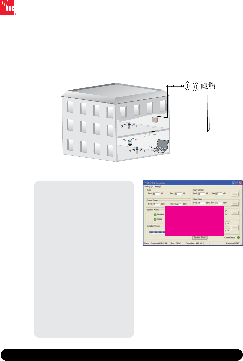
System Description
The repeater transmits RF in both directions to provide indoor wireless coverage. The device is connected
via coax to a donor antenna that is typically located on a rooftop or external wall of a building, directed
at the donor cell-site. The repeater is mounting inside the building and distributes the RF over coax to an
indoor antenna located in the desired coverage area.
Typical Installation
GUI Features
Automatic Level Control (ALC)
The system will control the output power to
maintain the stability and protect the unit.
Sleep Mode
Mode is activated when the reverse output RF
power shows below -65dBm for over 3 minutes.
The system re-activates to the wake up mode if
the signal reaches over -65dBm.
Band Selection
The BDA offers programmable band selection.
Isolation Check
There is isolation check for the forward path
and reverse path when the system is set up and
powered on.
User-friendly Interface
USB connection allows you to control;
• sleep mode
• band selection
• on/off system controls
Over Power Shut Down
The system can detect if there is excessive
power and will shut down to protect the unit
and will automatically resume operation when
normal power levels are reached.
FPO

7/07 • 105105AE In-building Wireless Repeaters
In-building Wireless Repeaters
850 MHz Cellular and 1900 MHz PCS
3
www.adc.com • +1-952-938-8080 • 1-800-366-3891
Typical Specifications
RF SPECIFICATION
Operating Frequency for the 1900 MHz
Down Link: 1930-1990 MHz
Up Link: 1850-1910 MHz
5MHz, 15MHz, or a combination of a 5 & 15MHz selectable
Operating Frequency for the 850 MHz
Down Link: 869-894 MHz
Up Link: 824-849 MHz
A, A’, A’’ OR B, B’ selectable
Output Power: +13dBm
Gain: 60dB
Flatness: +0dB, -4dB Full Band
Out of Band Gain: 45dB Offset 1MHz
35dB Offset 5MHz
NOISE FIGURE
Up Link: 5dB max
VSWR: 1.5 max
Frequency Stability: ±0.05ppM max
ALC: 20dB min
Gain Control Range: 10dB min
1dB Step
ACPR
CDMA 10FA: 45dBc @ 885KHz
50dBc @ 1.98MHz
Delay: 5usec max
Supply Voltage: 8 V
AC 110~220V to DC 8V SMPS Adaptor
Current Consumption: 3A max
DC 8V Current Consumption
ENVIRONMENTAL
Operating Temperature: -5°C ~ +45°C
Humidity 85%
INDICATORS/CONTROLS
USB Port: Gain, ALC Level Setting, Alarm
Sleep Mode: Up Link non signal (below-65dBm): Off
Input over -65dBm: On (in 1 sec)
Oscillation Check: Observation Down Link
LED: Shut Down +16dBm
Sleep Mode: (U/L, D/L)
Shutdown: (U/L, D/L)
Oscillation: (D/L)
Power
ALC On/Off: Setting from GUI
RF Connector: N Type (Donor ANT): Service ANT: SMA

Website: www.adc.com
From North America, Call Toll Free: 1-800-366-3891 • Outside of North America: +1-952-938-8080
Fax: +1-952-917-3237 • For a listing of ADC’s global sales office locations, please refer to our website.
ADC Telecommunications, Inc., P.O. Box 1101, Minneapolis, Minnesota USA 55440-1101
Specifications published here are current as of the date of publication of this document. Because we are continuously
improving our products, ADC reserves the right to change specifications without prior notice. At any time, you may
verify product specifications by contacting our headquarters office in Minneapolis. ADC Telecommunications, Inc.
views its patent portfolio as an important corporate asset and vigorously enforces its patents. Products or features
contained herein may be covered by one or more U.S. or foreign patents. An Equal Opportunity Employer
105105AE 7/07 Original © 2007 ADC Telecommunications, Inc. All Rights Reserved
Spec Sheet