Accurate Technology GPDS Transmitter User Manual PROSCALE Manual Rev E
Accurate Technology, Inc. Transmitter PROSCALE Manual Rev E
Contents
Users Manual Part 2
ProScale M150, M250 and all products with General Purpose LCD Digital Displays 11 of 11
Readheads
Absolute
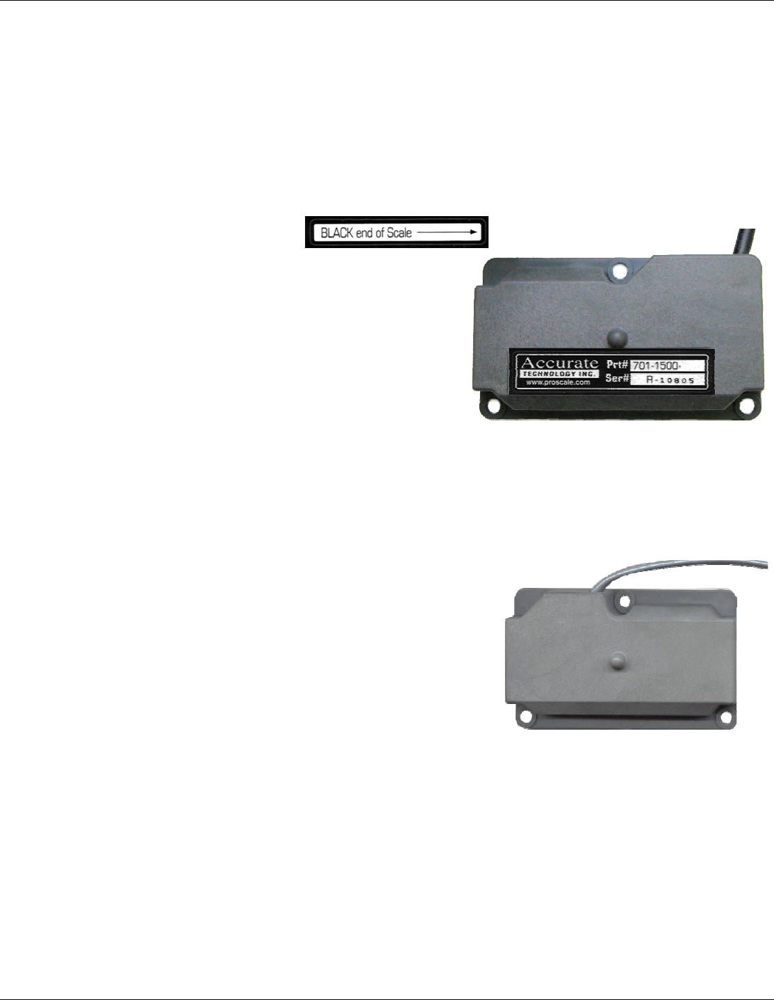
Absolute (ABS) style readheads have “BLACK END OF SCALE” labels on the cover,
and the wire exits from the corner of the housing. Care must be taken not to damage the
brass “fingers” inside the readhead housing. ABS style readheads, used in all Model 150
and Model 250 systems, must only be used on ABS scales and with a particular
orientation. Each readhead has an arrow on the label pointing in the direction of the
“BLACK END OF SCALE”.
Each ABS style scale will have one end painted
black. This relationship is very important, since the
readhead will work, but produce erratic results if
installed backwards. To insure proper operation, be
sure the arrow on the readhead is pointing toward
the BLACK end of the scale. The standard ABS
readhead has 3m (10 ft.) of cable. For special cable
lengths, contact Accurate Technology, Inc.
Standard ABS Readhead is supplied with a 3m (10ft) cable
OLD Part # 701-1510-001, NEW Part # 701-1500-120
Incremental
Incremental style readheads do not have labels on the
cover, and the wire exits from the center of the housing.
Care must be taken not to damage the brass “fingers”
inside the readhead housing. Incremental readheads
work on incremental scales ONLY. Orientation of
incremental readheads on the scale is not important.
Incremental readheads are still used on some current
Accurate Technology products such as: ProStop, ProKit,
Measuring Kits, ProCaliper, and ProPanel.
Standard Incremental Readhead is supplied with a 300mm (12in) cable
Old Part # 701-1002-002, NEW Part # 701-1500-N12
Avoid making extension cables. If a different cable length is required, contact Accurate
Technology, Inc.
Readheads used on Absolute and Incremental systems should never be mixed.
ProScale M150, M250 and all products with General Purpose LCD Digital Displays 12 of 12
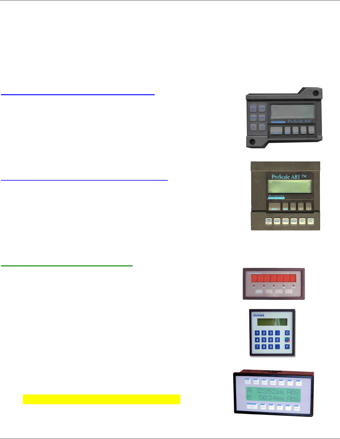
Digital Displays
Accurate Technology makes several different digital displays for use with ProScale
products. Each display has unique features that make it suitable for different
applications. The following is a listing of the displays and their descriptions:
General Purpose Surface Mount
Basic (no auxiliary keys) 2AA Bat. 701-1600-120
NEW Part # Effective April 2004: 700-1600-220
Full Fuctionality, 2AA Battery 701-1600-100
NEW Part # Effective April 2004: 700-1600-200
Full Fuctionality, 24VDC 701-1605-100
NEW Part # Effective April 2004: 700-1600-205
General Purpose 1/4 DIN Panel Mount
Full Fuctionality, 2D Battery 701-1570-100
NEW Part # Effective April 2004: 700-1600-400
Full Fuctionality, 24VDC 701-1560-500
NEW Part # Effective April 2004: 700-1600-300
Operation Instructions Included in this Manual
Other Digital Displays
1/8 DIN Panel Mount
24VDC LED, 700-1600-090
RS485 Output
1/4 DIN Panel Mount
24VDC Backlit LCD 700-1600-110
Position Control Unit
Dual Input Panel Mount
24VDC 2 line Backlit LCD 700-1600-500
2 inputs, A+B, A-B, RS232 out
Operation Covered in Separate Manual

ProScale M150, M250 and all products with General Purpose LCD Digital Displays 13 of 13
Product Specifications
ProScale Model 150 & Model 250
Measuring Range*:
Model 150: 2 Standard Sizes:
0-250mm (10in) and 0-450mm (18in)
Model 250: 9 Standard Sizes:
0 to 300mm, 600mm, 1.3m, 2.4m, 3.0m, 3.6m, 6.0m
(0 to 12in, 24in, 52in, 96in, 120in, 144in, 240in )
Accuracy: + (.025 + .064 x L / 430) mm; max error + 0.20mm @ 1.3 to 6m
+ (.001 + .0025 x L / 17) in; max error + .008in @ 4 to 20 feet
(L = length of measurement in mm or inches)
Resolution .1mm/.01cm/.01in; .01mm/.001cm/.001in; .01mm/.001cm/.0004in
Repeatability: .01mm or .001cm or .001in
Display Range: + 9999.99 mm; + 999.999 cm; + 999.999 in; + 399 63/64 in
Operating Temp: 0 to 51°C; 32 to 120°F
Temp Coef: 25ppm/°C; 13ppm/ °F
Max. Slew Rate: 400 mm/sec. (15 inches/sec.)
Available Displays: General Purpose Surface Mount LCD
(Digital Readouts) General Purpose 1/4 DIN Panel Mount LCD
1/8 DIN Panel Mount LED
1/4 DIN Panel Mount Position Control LCD
Dual Input Panel Mount LCD
Accessories: See Section 6
Output Format: Mitutoyo SPC, RS232, RS485 (Selected displays)
Readhead: 3m (10’), six-conductor cable terminated by RJ12 connector.
(Maximum cable length 6m)
Dimensions: Available at www.proscale.com.
US Patents: 4420754, 4879508, 4878013, 4959615
Warranty: Three years from date of purchase.
All ProScale products are MADE IN USA
* MEASUREMENT lengths are approximately 100mm (4in) shorter than PHYSICAL lengths.
ProScale M150, M250 and all products with General Purpose LCD Digital Displays 14 of 14
SECTION 2 P
ROSCALE MODEL 150
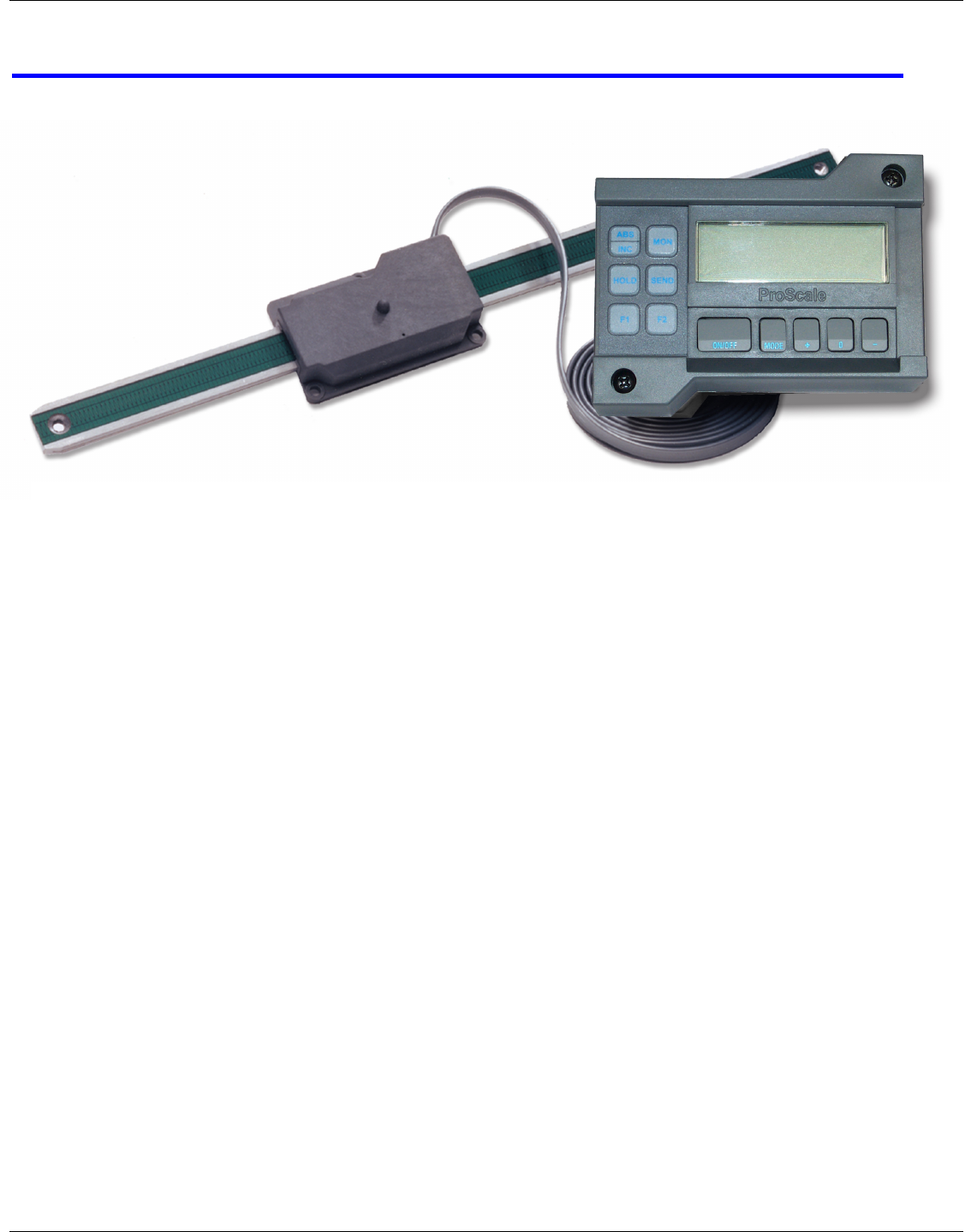
ProScale Model 150
A General Purpose measuring system with standard measuring ranges of 250mm (10”)
or 450mm (18”).
Model 150 systems use ABS style scales, ABS style readheads, and any of the available
digital displays. Neither the scale nor readhead are compatible with any Accurate
Technology incremental technology measuring systems.
ProScale Model 150 is easy to install. By following the basics of good installation,
reliable, error-free operation can be expected. ProScale M150 can be used in many
different measurement applications, and with numerous types and brands of equipment.
Therefore all installations will be a little different and it is the responsibility of the installer
to choose the bolts, screws, or other mounting hardware that guarantee proper
installation for optimum operation.
Note: If a custom kit was ordered which contains instructions for installing ProScale on a
specific product, follow those instructions rather than the general instructions here.
ProScale Model 150-10 shown with Surface Mount General Purpose LCD Digital Display
ProScale M150, M250 and all products with General Purpose LCD Digital Displays 15 of 15
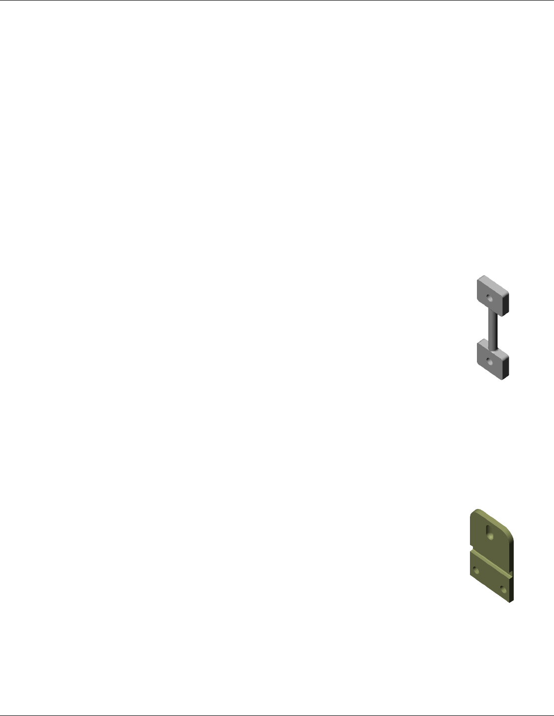
Connector Link
Guide Cli
p
Installation
1. Note the orientation of the readhead on the scale. Be sure the arrow on the
readhead points towards the “BLACK END OF SCALE”. This orientation is critical
for proper operation of ProScale. Be sure the mounting location for the readhead
and scale will allow this orientation. Take care when sliding the readhead onto the
scale so the brass “fingers” inside the readhead do not get damaged. (A slight
“wiggling” motion when installing the readhead on the scale will simplify the
process.)
2. Determine an appropriate mounting location for the system. Most applications of
the Model 150 will have the readhead held stationary while the scale is passed
through the readhead. The ProScale will also operate properly if the readhead is
moved along the scale (see figures on next page).
3. If the readhead is to be mounted stationary, the scale should be
attached to a moving part of the measuring application or machine
using the Connector Link.
Mount the readhead using three screws or bolts. Mount one end of
the connector link to the scale using an M5 (or 10-32) screw and the
other end to the moving part. Check that the scale is properly
aligned with the direction of motion of the moving part. Be sure
both connections are secure or inaccurate/erratic readings
could result. (The connector link compensates for small
misalignments of the installation and acts as a shear pin). The connector link must
be mounted in the same direction as the scale (see figure below).
Note: Failure to use the connector link could void the warranty.
4. If you choose to hold the scale stationary and move the readhead to measure, you
should use the Guide Clip to move the readhead along the scale
(see figure on next page). The connector link is not necessary in
this configuration.
Mount the scale using a M5 (or 10-32) screw. Be sure the scale is
properly aligned as the readhead is moved (the Guide Clip will
compensate for slight misalignment in one direction only). Adjust
scale alignment if necessary.
For accurate measurements, the guide clip must be mounted
perpendicular to the direction of travel of the readhead. The guide
clip should exert some pressure over the full range of travel on the readhead so the
two move as a single unit.
Note: Failure to use the guide clip could void the warranty.