Accurate Technology GPDS Transmitter User Manual PROSCALE Manual Rev E
Accurate Technology, Inc. Transmitter PROSCALE Manual Rev E
Contents
Users Manual Part 7
ProScale M150, M250 and all products with General Purpose LCD Digital Displays 36 of 36
Jumpers – Surface Mount Display
Although the ProScale display uses a keyboard-programming mode to enable and
configure features in the unit, several selection jumpers are located on the circuit board
for additional system configuration.
User configurable jumpers consist of three pins and a ‘shorting block’.
The center of these pins is ‘Common’. One end pin is labeled ‘A’ and the other end pin is
labeled ‘B’.
Surface Mount Display
Circuit Board
JP1 FOR FACTORY USE ONLY
JP2 Absolute/Incremental Encoder Selection
The General Purpose Digital Display supports both Incremental and Absolute style
measuring systems (See Section 1: ProScale Terminology). To configure the display for
use with absolute (ABS) type encoders (default), install the shorting jumper in position A.
For incremental type encoders, install the shorting jumper in position B.
(ProScale Model 150 & 250 are Absolute systems. Other Accurate Technology products
such as ProCaliper, ProPanel, Measurement Kits, and ProStop are Incremental systems)
NOTE: This functionality is not related to the ABS / INC measurement modes described
in Section 4: Auxiliary Keypad.
JP3 Programming Enable/Disable
Entry to the programming mode of the ProScale display can be enabled or disabled
based on this jumper setting. To enable keyboard programming (default), install the
shorting jumper in position A. To disable keyboard programming, install the shorting
jumper in position B. When programming mode is disabled, the user cannot access the
programming functions via the Mode + 0 keys as described in the Section 4:
Programming. This provides the user with a method of configuring the display with
specific parameters and prevents unauthorized configuration changes.
JP4 Display Power
This jumper configures the Digital Display to operate on either Battery or 24VDC.
This jumper will be set at the factory based on the type of display you have ordered.
JP5 FOR FACTORY USE ONLY
JP1 JP2
JP3 JP4
JP5
ProScale M150, M250 and all products with General Purpose LCD Digital Displays 37 of 37
Jumpers – Panel Mount Display
Although the ProScale display uses a keyboard-programming mode to enable and
configure features in the unit, several selection jumpers are located on the circuit board
for additional system configuration.
User configurable jumpers consist of three pins and a ‘shorting block’.
The center of these pins is ‘Common’. One end pin is labeled ‘A’ and the other end pin is
labeled ‘B’.
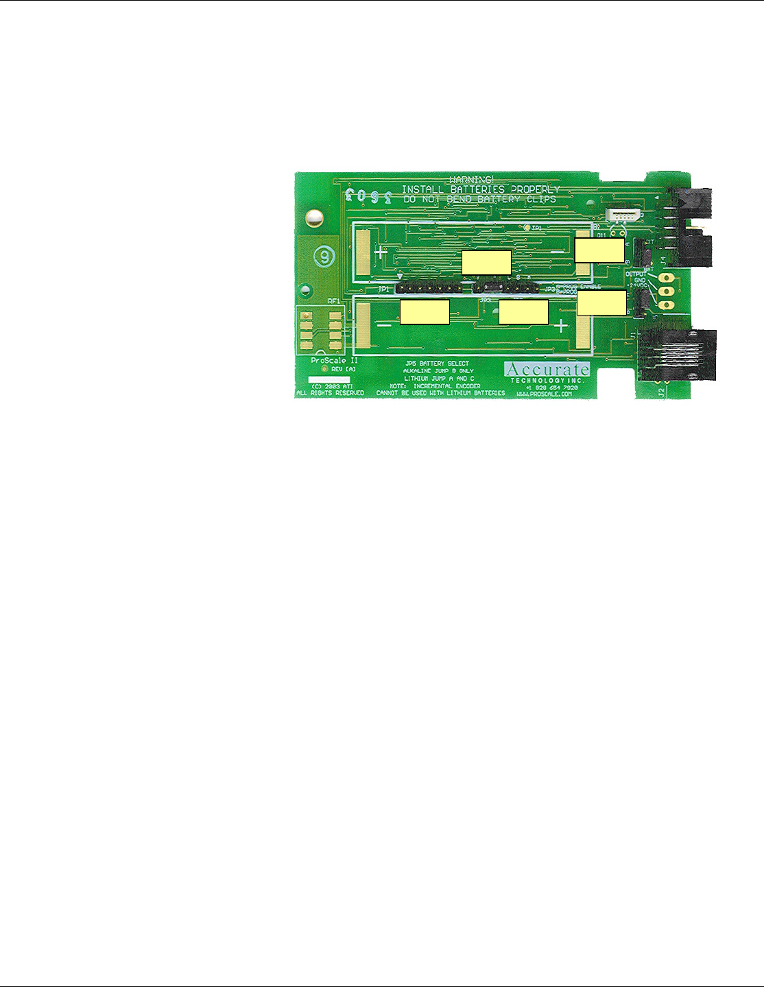
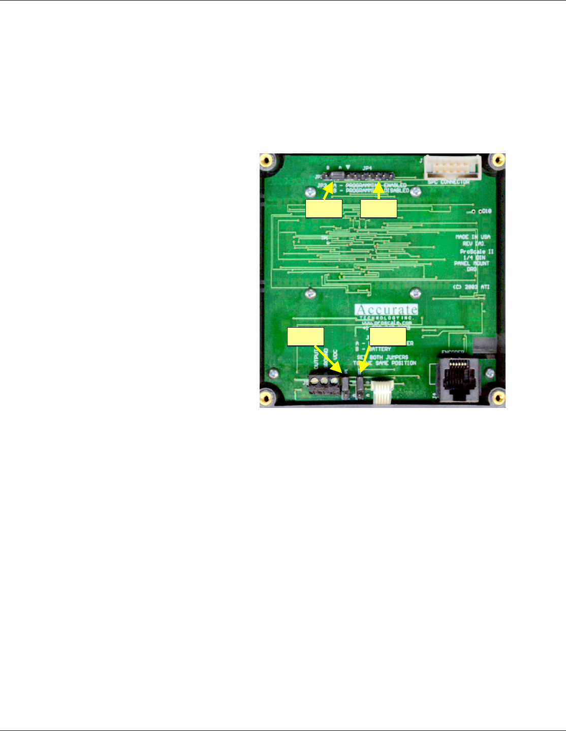
Panel Mount Display
Circuit Board
JP1 & JP2 Display Power
These jumpers set the display to operate on either 2D batteries or 24VDC.
To configure the display to operate on 24VDC power JP1 AND JP2 should be set to
position A THEY MUST BE SET ON THE SAME SETTING
To configure the display to operate on battery power JP1 AND JP2 should be set to
Position B THEY MUST BE SET ON THE SAME SETTING
JP3 Programming Enable/Disable
Entry to the programming mode of the ProScale display can be enabled or disabled
based on this jumper setting. To enable keyboard programming (default), install the
shorting jumper in position A. To disable keyboard programming, install the shorting
jumper in position B. When programming mode is disabled, the user cannot access the
programming functions via the Mode + 0 keys as described in the Section 4:
JP4 FOR FACTORY USE ONLY
JP1 JP2
JP3 JP4

ProScale M150, M250 and all products with General Purpose LCD Digital Displays 38 of 38
Programming Summary
Programming Factory Works with Digital Display:
Parameter Function Default Basic 2AA 2D 24VDC
Pr0 Encoder Direction 0 ◙ ◙ ◙ ◙
Pr1 Segment Offset 1 - On ◙ ◙ ◙ ◙
Pr2 High Speed ReadHead 0 - Off ◙ ◙ ◙ ◙
Pr3 Zero, Offset Entry 1 - Enable ◙ ◙ ◙ ◙
Pr4 Display Resolution 1 - Normal ◙ ◙ ◙ ◙
Pr5 mm or cm 0 - mm ◙ ◙ ◙ ◙
Pr6 Fractions, mm, in 0 - all ◙ ◙ ◙ ◙
Pr7 Scaling 1.000 (none) ◙ ◙ ◙ ◙
Pr8 Auto off 15 - 15 min. ◙ ◙ ◙ ◙
Pr9 Auxiliary Keypad 7 - all keys ◙ ◙ ◙
Pr10 Offset Addition 0 - disabled ◙ ◙ ◙
Pr11 Offset Addition 1 1.000 Inch ◙ ◙ ◙
Pr12 Offset Addition 2 1.500 Inch ◙ ◙ ◙
Pr13 Offset Addition 3 2.000 Inch ◙ ◙ ◙
Pr14 Output Mode 0 - drift ◙
Pr15 Output Polarity 0 - N/O ◙
Pr16 Lower Limit 0.000 ◙ ◙ ◙ ◙
Pr17 Upper Limit 5.000 Inch ◙ ◙ ◙ ◙
Pr18 Drift Tolerance .01 Inch ◙ ◙ ◙
Pr19 Auto Monitor ON 0 - disabled ◙ ◙ ◙
Pr20 Auto Monitor OFF 0 - disabled ◙ ◙ ◙
Pr21 Auto Monitor Distance .500 Inch ◙ ◙ ◙
Pr22 Backlight On 1 - 3 seconds ◙
Pr23 FUTURE FEATURE 1
Pr24 FUTURE FEATURE 0
Pr25 FUTURE FEATURE 0

ProScale M150, M250 and all products with General Purpose LCD Digital Displays 39 of 39
Jumpers and Key Press Summary
Circuit Board Jumpers
JUMPER SURFACE MOUNT DISPLAY PANEL MOUNT DISPLAY
JP1 Internal Use Only Power Selection (set same as JP2)
JP2 Absolute (ABS) or Incremental System Power Selection (set same as JP1)
JP3 Programming Enable/Disable Programming Enable/Disable
JP4 Display Power – Battery or 24VDC Internal Use Only
JP5 Internal Use Only N/A
Key Press Functions:
ON/OFF (Press & Hold) + MODE (Momentarily)
Enable/Disable LOCK mode (‘0’, ‘+’ & ‘-‘ keys).
MODE (Press & Hold) + ‘0’(Momentarily)
Enter or Exit Programming Mode
While in Programming mode:
MODE (Momentarily)
Advances through the Programming Parameter list.
ON/OFF (Press & Hold) + MODE (Momentarily)
Steps backwards in Programming Parameter list
+ (Momentarily) while displaying a Programming Parameter
Increases the Parameter setting.
- (Momentarily) while displaying a Programming Parameter
Decreases the parameter setting.
0 (Momentarily) while displaying a Programming Parameter
Reverts the parameter to its Factory Default setting.
MODE (Press & Hold + ‘+’ or ‘-‘(Momentarily)
Apply Segment Offset Adjustment
ON/OFF (Momentarily)
Turn Display power on or off
ON/OFF (Press & Hold) for 5 seconds
Display Battery Voltage
ON/OFF + MODE (Press & Hold Both keys) for 10 seconds (with display power off)
LCD Segment Test & sets ALL Programming parameters to factory defaults
How long a key is depressed, and the combination of the keys pressed is important. The
term (Momentarily) describes a key press of typically less than 1 second. Whereas
(Press & Hold) is used imply a key press of typically longer than 1.5 seconds.
For example: When using a PC keyboard to type a CAPITAL letter you would “press and
hold” the SHIFT key and “momentarily” depress the LETTER key.
In addition, a key(s) “function” is executed on the key RELEASE, not the key DEPRESS
of that key(s). This is important since some keys execute different functions based on
how long they are depressed. These key operations, once tried, quickly become intuitive.

ProScale M150, M250 and all products with General Purpose LCD Digital Displays 40 of 40
SECTION 5 M
ISCELLANEOUS
Frequently Asked Questions
What does “no Enc” mean?
If the readhead is off the scale, or the readhead cable is unplugged from the digital
display, an “no Enc” will appear on the display. To clear error:
1. Be sure the readhead is on the scale.
2. Unplug the connector from the display for one second.
3. Reconnect the readhead cable to the digital display.
The battery clips seem to be very loose. Is this normal?
Yes. DO NOT attempt to bend these clips or wedge anything between them and
the case. These clips are designed to expand when the two case halves are
screwed together.
Can I mount the scale/readhead without the connector link/guide clip?
The connector link and guide clip serve to provide an accurate method of
transferring the movement of the moving part to the readhead or scale, while also
absorbing any stresses that may occur. If they are not used, the warranty could be
voided.
The display reads numbers but they seem to be random.
Be sure the readhead is oriented correctly on the scale. One end of the scale is
black. Be sure that the arrow on the readhead is pointed in the correct direction.
The display does not change as the scale/readhead moves.
The display is in the HOLD mode. Press & release the Hold button.
Product Communication
ProScale's electrical interface allows the readhead position to be read directly or through
the digital display by a computer or other data acquisition device. Interface diagrams are
available upon request.
ProScale M150, M250 and all products with General Purpose LCD Digital Displays 41 of 41
Abbe Error
Abbe error is a condition that may not be visible to the human eye, but will affect linear
measurements. Be sure to take precautions when installing ProScale in order to eliminate
the possibility for Abbe error.
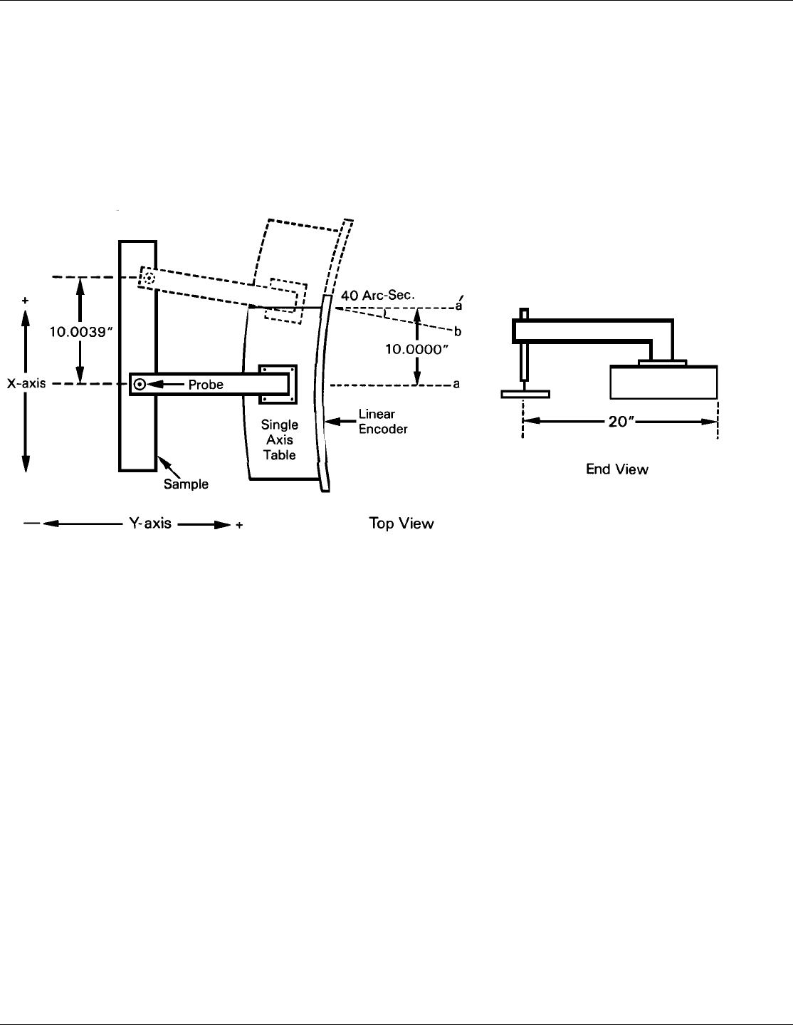
Abbe error refers to a linear error caused by the combination of an angular error and a
dimensional offset between the sample and the measuring system. It is important to
understand that the information the encoder is providing is only the position of the
readhead on the scale. To illustrate this, see the figure, which shows a linear
measuring device. (The apparent distortion in the measuring device is intentional - for this
example - to show the measuring device with a curvature in its mounting.)
Suppose the curvature in the figure is sufficient to produce an angle of 40 arc-seconds. If
the measuring device moves 10 inches, the probe will be found to have moved 10.0039
inches, resulting in an error of +0.0039 inches. Abbe error could be lessened by moving
the measuring system closer to the sample. This effectively solves one half of the Abbe
error problem (offset) and leaves only the angular mounting problem to be solved.
Angular error can best be countered through proper design and placement of the linear
scale. Sources of angular error include:
1. Mounting the linear scale to an imperfectly flat surface.
2. Mounting the linear scale to an imperfectly straight surface.
3. Curvature of ways (or linear bearings) used to measure the sample.
4. Contaminants between the probe and item being measured.
5. Friction in any part(s) of the measuring device.