Acroprint Time Recorder 1207 Proximity Reader User Manual 111303 Qstart
Acroprint Time Recorder Company Proximity Reader 111303 Qstart
Contents
- 1. User Info Box
- 2. User Manual
- 3. Marketing User Info
User Manual
You will need the following items:
• Attendance Rx™ software
(may already be installed, PN: 08-0137-000)
• ATRx ProxTime™
(ATRx 10 Proximity Terminal, PN: 01-0206-000)
• 50 ft. RS232 ATR Communications Cable
provided by Acroprint (PN: 72-0146-004)
• RJ11/DB 9-pin ATR Serial Adapter
provided by Acroprint (PN: 63-0163-003)
• DC 12V Power Adapter
(PN: 56-0126-000)
• 15 Proximity Badges
(PN: 14-0123-002)
Attendance Rx must be installed prior to initial setup
and connection of ATRx10 proximity terminal. If
software is already installed proceed to step 2 of
Quick Start. If not, install Attendance Rx software by
inserting CD into CD-Rom. Follow and complete the
installation wizard.
To ensure PC meets the minimum system requirements,
see product box or refer to www.acroprint.com.
ATRx ProxTime Quick Start
www.acroprint.com
1. Make sure PC is completely shut off.
To avoid damage to the PC port; PC power must be
completely shut off prior to attaching the ATR adapter
and ATR communications cable.
2. Connect ATR adaptor and ATR communications
cable (this may already be connected at the factory).
3. Connect the ATR adapter to the serial port on the
back of your PC.
4. Connect ATR communications cable to the white
port on the back of the ATRx10 proximity terminal.
** Do not connect to telephone wall outlet.
** Do not connect to modem port.
5. Plug DC 12V Power Adapter into the back of the
ATRx10 proximity terminal. ATRx10 will display PC
on the LCD screen until your PC is powered ON and
the Attendance Rx program is running.
Power on your PC and Attendance Rx should be
running. To confirm software is running, a System
Tray Icon will appear in the bottom right-hand corner
of your computer desktop screen
To enable ATRx
Terminal Manager, right
click the System Tray
icon, select Enable
Terminal Manager.
Software may automatically locate the PC serial
port. After the start-up sequence the Time and Day
of Week will display on the ATRx10 screen.
Note: If the connection fails the letters PC will dis-
play on ATRx10 screen. If this occurs, repeat steps
in Quick Start step 2 to ensure connections are
correct and proceed to Trouble Shooting portion on
the reverse side of the Quick Start.
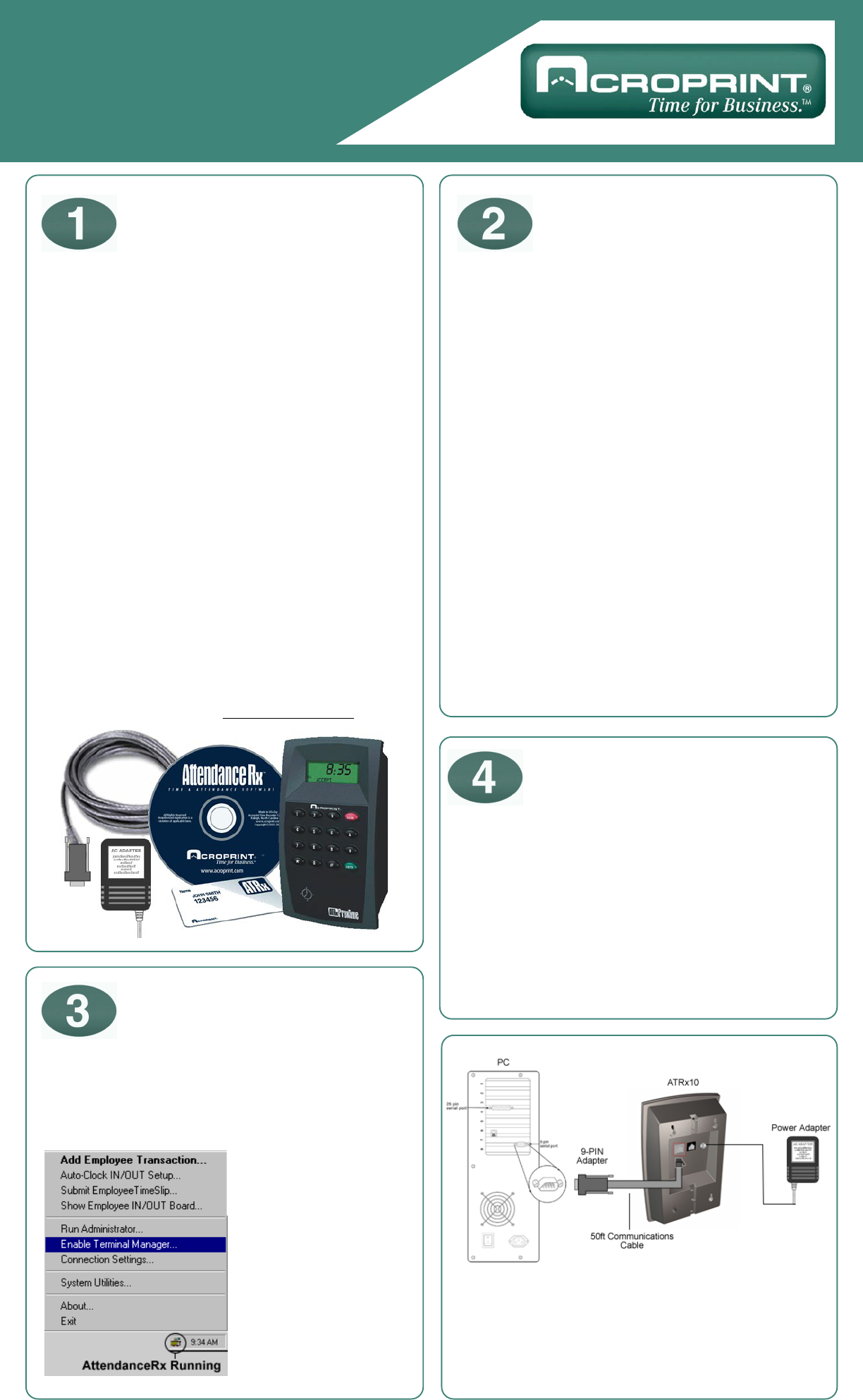
Getting Started Connect ATRx10
to IBM Compatible PC
Power Connection
Verify Terminal is
Communicating with PC
After following these steps, your set-up
should look like this diagram.
*Use enclosed wall template and four screws
to mount unit to wall stud.
ATRx ProxTime Quick Start
www.acroprint.com
Verify you are using the equipment supplied by Acroprint: connections cable, serial adapter, power
adapter.
Verify program is running. Refer to Step 2 of Quick Start (reverse side of this document).
Check connections on the back of the PC to confirm the adapter and cable supplied by Acroprint are
securely attached to a serial communications port.
Confirm the cable supplied by Acroprint is plugged into the correct port on the ATRx terminal.
Cycle the power to the ATRx terminal by unplugging the DC 12V power adapter from wall outlet for
two to five seconds, then plug back into the wall outlet.
Restart Windows. Once computer login is complete, verify program is running (Refer to Step 2 of
Quick Start).
Any additional questions, contact Acroprint’s Technical Support Department.
WEB: www.support.acroprint.com FAX: 919.872.5967
TOLL FREE: 1.800.334.7190, option 3. EMAIL: supportdept@acroprint.com
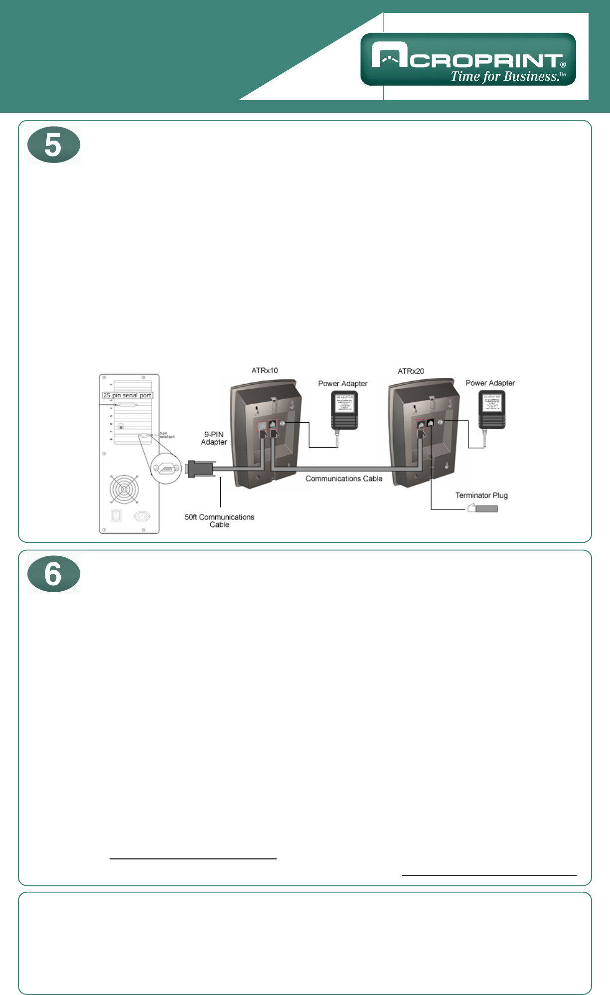
Connecting Additional Terminals
Troubleshooting the ATRx10
and ATRx20 Terminal Connections
NOTE: This equipment has been tested and found to comply with the limits for a Class A digital device, pursuant to Part 15 of
the FCC Rules. These limits are designed to provide reasonable protection against harmful interference when the equipment is
operated in a commercial environment. This equipment generates, uses, and can radiate radio frequency energy and, if not
installed and used in accordance with the instruction manual, may cause harmful interference to radio communications.
Operation of this equipment in a residential area is likely to cause harmful interference in which case the user will be required to
correct the interference at his own expense.
This Class A digital apparatus complies with Canadian ICES-003. Cet appareil numerique de la classe A est conforme a la
norme NMB-003 du Canada.
Make sure PC power is ON and the Attendance Rx software program is running
(see step 2 on reverse side of this Quick Start ).
Plug communications cable into the available black port on the ATRx10 terminal. Connect the other end
of the cable into the first black port on the ATRx20 terminal.
*This cable is design for RS485 communications. It is available for purchase through Acroprint, please call
for more information (1.800.334.7190).
Insert the Terminator Plug into the remaining open RS485 port on the last ATRx20 terminal that is on the
chain of terminals.
Plug DC 12V power adapter into the back of the ATRx20 and the wall outlet.
Time and Day of Week will display on the screen of the ATRx 20 terminal, if connection is established.