Adura Technologies LCR10P2 Lighting control for commercial and industrial buildings User Manual LC Manual 01
Adura Technologies, Inc. Lighting control for commercial and industrial buildings LC Manual 01
Contents
- 1. Antenna installation instructions
- 2. Users Manual
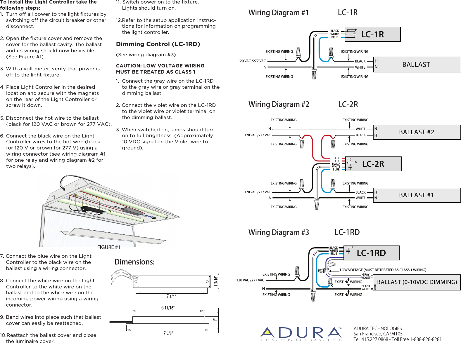
- 3. Installation Manual
Installation Manual