Adura Technologies LCR10P2 Lighting control for commercial and industrial buildings User Manual Light Controller Manual Final
Adura Technologies, Inc. Lighting control for commercial and industrial buildings Light Controller Manual Final
Contents
- 1. Antenna installation instructions
- 2. Users Manual
- 3. Installation Manual
Users Manual
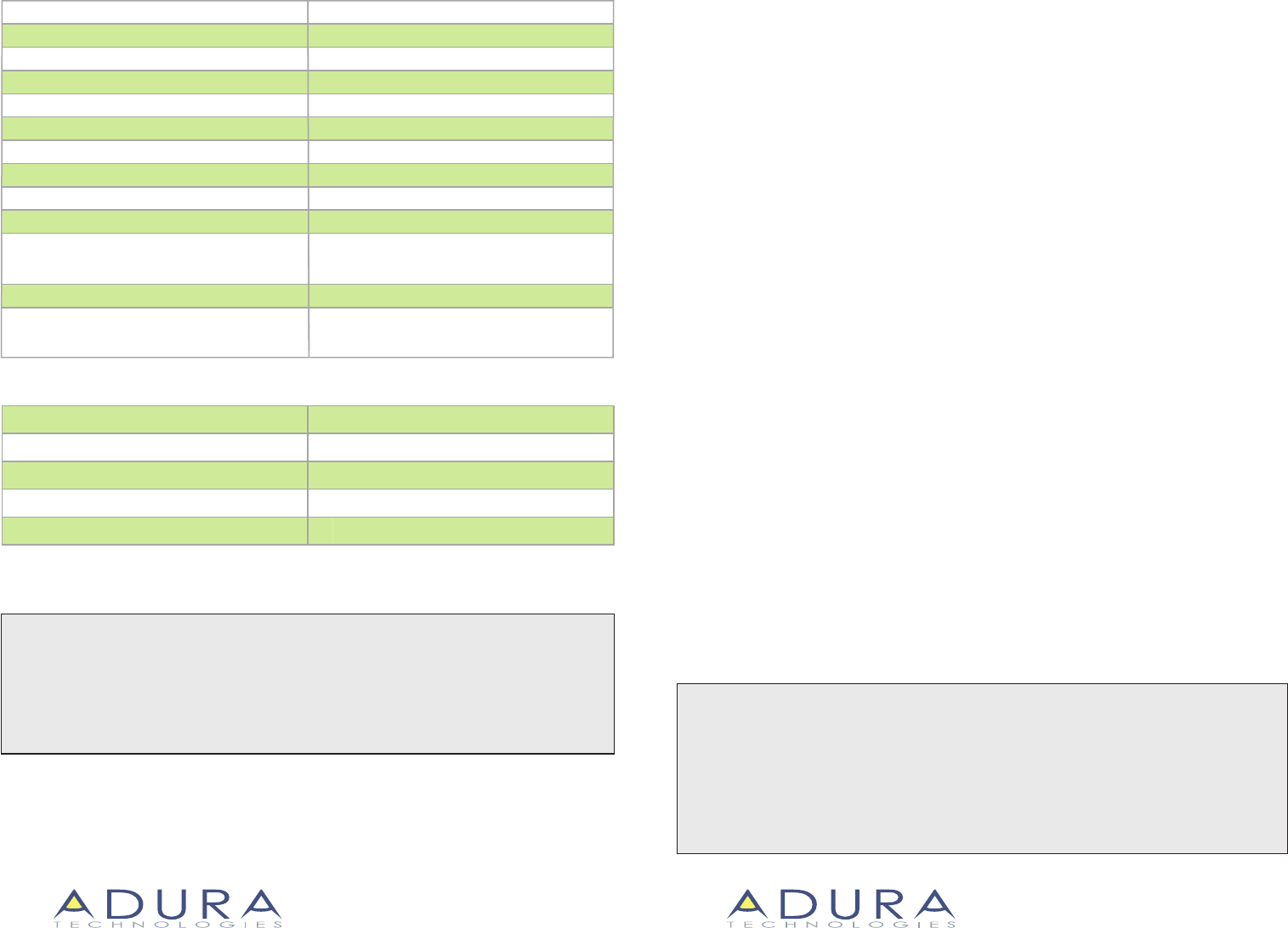
Specications:
Ordering Information:
LC - 1R
LC Instructions 06.09
Single relay
LC - 2R Two relay
Optional external antenna
XA
Catalog Number Description
ADURA TECHNOLOGIES™
San Francisco, CA 94105
Tel: 415.227.0868 • Toll Free 1-888-828-8281
ADURA TECHNOLOGIES™
San Francisco, CA 94105
Tel: 415.227.0868 • Toll Free 1-888-828-8281
w w w . a d u r a t e c h . c o m
light controller
Input Voltage:
Input Frequency:
Relays:
Max Switched Current:
Radio Frequency:
RF Transmission Output Power (Average):
100 – 277 VAC
60 Hz
Normally open, SPST, zero crossing control
5A Ballast/5A Tungsten (LC-2R = 5A x 2 relays)
2.4 GHz
+12 dBm
Mounting: Magnets or screws inside of a UL-rated xture
or enclosure rated for the application
Dimensions:
Operating Environment: 40 to 140 deg F
Memory: Conguration programming
stored in non-volatile memory
Current measurement:
Voltage measurement: 2% accuracy full scale
2% accuracy full scale
Wires: 24” 600 VAC Rated, 18 AWG solid conductors
7” 5/8 L x 1“ 3/16 W x 1” H
CAUTION
• Disconnect all incoming power before installation or service.
• All installation and maintenance work must be performed by qualied personnel.
• The Light Controllers must be installed in accordance with state, local and national
electrical codes and requirements.
• The Light Controller must be installed within a UL-rated xture or enclosure rated for
this application.
INSTALLATION
INSTRUCTION MANUAL
The Light Controller is to be used to control lighting in commercial and industrial buildings.
It provides control of lights (on/o or dimming) by means of commands transmitted and
received via radio frequency.
The Light Controller is intended to be used in a network of devices which communicate
wirelessly, such as wall switches, occupancy sensors, gateways and software management
tools.
The Light Controller is to be mounted inside the enclosure of a light xture or in a separate
UL-rated enclosure. In the case of uorescent lights, the Light Controller is to be installed
inside the ballast cavity of a standard uorescent luminaire.
The Light Controller is intended to be used to control uorescent ballasts, incandescent
lights, LED drivers and HID ballasts.
There are 3 models of the Light Controller:
• LC-1R has one relay and is intended to control one light xture or group of light xtures.
• LC-2R has two relays and is intended to control two levels of light within one xture or
two xtures or two groups of light xtures.
• LC-1RD has one relay and a low voltage dimming output (Class 1 rated) intended to
control standard 0-10 VDC dimming ballasts. Each LC-1RD can provide dimming control to
a maximum of 5 standard 0-10 VDC dimming ballasts.
LC - 1RD Single relay with 0-10 VDC dimming
TM TM
Installation Materials (Not Supplied)
Wiring connectors. All existing wiring connectors must be replaced with new UL listed
wiring connectors, either wire nuts or captive-type connectors. All wiring connectors must
be correctly sized for the application, the number and the size of the electrical conductors.
Sheet metal screws. As an option, the Light Controller can be secured with 2 #8 sheet metal
screws.
This equipment has been tested and found to comply with the limits for a Class A digital device, pursuant to Part 15 of the
FCC Rules. These limits are designed to provide reasonable protection against harmful Interference when the equipment
is operated in a commercial environment. The equipment generates, uses and can radiate radio frequency energy and, if
not installed and used in accordance with the instruction manual, may cause harmful interference to radio communica-
tions. Operation of the equipment in a residential area is likely to cause harmful interference in which case the user will be
required to correct the interference at his/her own expense.
Class A Digital Devices
WARRANTY INFORMATION
Adura Technologies
™
warranties its products to be free of defects for a period of ve years. Adura Technologies will, at its option,
repair or replace any product that is defective in materials or manufacture that is returned to ADURA within the warranty period.
This warranty is void if this product has been installed improperly or in an improper environment, overloaded, misused, or altered
in any manner, or not installed in accordance with any labels or instructions. Adura Technologies is not liable for incidental, indirect,
special, or consequential damages, including without limitation, damage to, or loss of use of property, revenue or prot. This
warranty does not cover the cost of installation, removal or reinstallation.
To comply with RF exposure compliance requirements, for mobile congurations, a separation distance of at least 20 cm must be
maintained between the antenna of this device and all persons. This device must not be co-located or operating in conjunction with
any other antenna or transmitter.
1 3/16”
7
1/4”
Installation Instructions:
1. Turn o all power to the light xtures by
switching o the circuit breaker.
2. Open the xture cover and remove the cover
for the ballast cavity. The ballast and its wiring
should now be visible. (See Figure #1)
3. With a volt meter, verify that power is o to the
light xture.
4. Place Light Controller in the desired location and
secure with the magnets on the rear of the Light
Controller or screw it down.
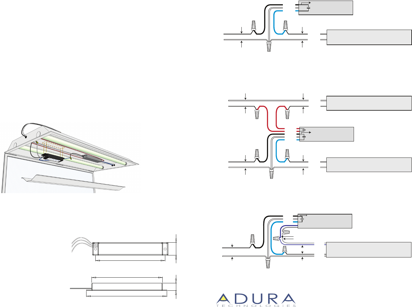
5. Disconnect the hot wire to the ballast
(black for 120 VAC or brown for 277 VAC).
6. Connect the black wire on the Light Controller
wires to the hot wire (black for 120 VAC or brown
for 277 VAC) using a wiring connector (see wiring
diagram #1 for one relay and wiring diagram #2
for two relays).
7. Connect the blue wire on the Light Controller
to the black wire on the ballast using a wiring
connector. For the LC-2R, connect the red wires
as shown in wiring diagram #2.
8. Connect the white wire on the Light Controller
to the white wire on the ballast and to the white
wire on the incoming power wiring using a
wiring connector.
9. Bend wires into place such that ballast cover
can easily be reattached.
10.Reattach the ballast cover and close the
luminaire cover.
11. Switch power on to the xture. Lights should
turn on.
12.Refer to the setup application instructions for
information on programming the light
controller.
Dimming Control (LC-1RD)
(See wiring diagram #3)
CAUTION: LOW VOLTAGE WIRING
MUST BE TREATED AS CLASS 1
1. Connect the gray wire on the LC-1RD to the gray
wire or gray terminal on the dimming ballast.
2. Connect the violet wire on the LC-1RD to the
violet wire or violet terminal on the dimming
ballast.
3. When switched on, lamps should turn on to full
brightness. (Approximately 10 VDC signal on the
violet wire to ground).
Dimensions:
6
11/16”
7
5/8”
1”
Wiring Diagram #1 LC-1R
FIGURE #1
ADURA TECHNOLOGIES™
San Francisco, CA 94105
Tel: 415.227.0868 • Toll Free 1-888-828-8281
TM
120 VAC /277 VAC
EXISTING WIRING EXISTING WIRING
EXISTING WIRING EXISTING WIRING
BALLAST
H
N
LC-1R
WHITE
N
BLACK
BLUE
WHITE
BLACK
Wiring Diagram #3 LC-1RD
Wiring Diagram #2 LC-2R
120 VAC /277 VAC
RED
RED
BLACK
WHITE
BLUE
BALLAST #2
N
H
N
LC-2R
WHITE
N
EXISTING WIRING EXISTING WIRING
EXISTING WIRING EXISTING WIRING
EXISTING WIRING EXISTING WIRING
EXISTING WIRING EXISTING WIRING
120 VAC /277 VAC BLACK BALLAST #1
N
H
BLACK
WHITE
120 VAC /277 VAC
EXISTING WIRINGEXISTING WIRING
EXISTING WIRING
N
LC-1RD
BALLAST (0-10VDC DIMMING)
H
N
BLACK
WHITE
BLUE
BLACK
WHITE
GRAY
VIOLET
EXISTING WIRING
LOW VOLTAGE (MUST BE TREATED AS CLASS 1 WIRING)