Alcatel Canada 24T28A01D22C 7390 24 GHz Co-Pol RBS User Manual BS Manual pages 229 to 246
Alcatel Canada Inc 7390 24 GHz Co-Pol RBS BS Manual pages 229 to 246
BS Manual pages 229 to 246
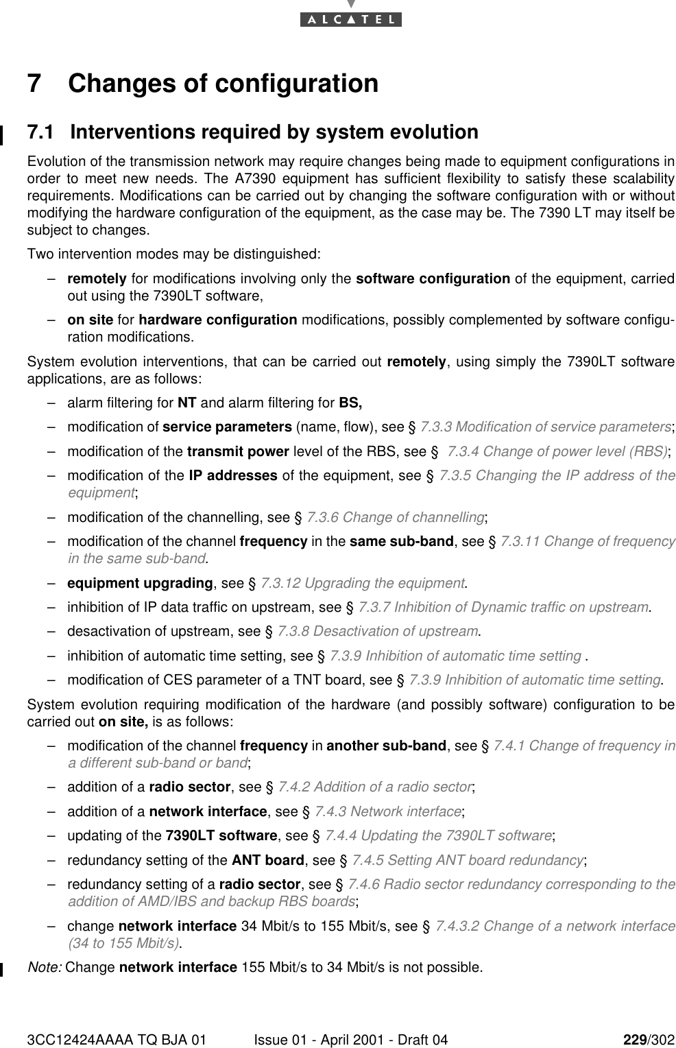
3CC12424AAAA TQ BJA 01 Issue 01 - April 2001 - Draft 04 229/3022467 Changes of configuration7.1 Interventions required by system evolutionEvolution of the transmission network may require changes being made to equipment configurations inorder to meet new needs. The A7390 equipment has sufficient flexibility to satisfy these scalabilityrequirements. Modifications can be carried out by changing the software configuration with or withoutmodifying the hardware configuration of the equipment, as the case may be. The 7390 LT may itself besubject to changes.Two intervention modes may be distinguished:–remotely for modifications involving only the software configuration of the equipment, carriedout using the 7390LT software,–on site for hardware configuration modifications, possibly complemented by software configu-ration modifications.System evolution interventions, that can be carried out remotely, using simply the 7390LT softwareapplications, are as follows:–alarm filtering for NT and alarm filtering for BS,–modification of service parameters (name, flow), see § 7.3.3 Modification of service parameters;–modification of the transmit power level of the RBS, see §  7.3.4 Change of power level (RBS);–modification of the IP addresses of the equipment, see § 7.3.5 Changing the IP address of theequipment;–modification of the channelling, see § 7.3.6 Change of channelling;–modification of the channel frequency in the same sub-band, see § 7.3.11 Change of frequencyin the same sub-band.–equipment upgrading, see § 7.3.12 Upgrading the equipment.–inhibition of IP data traffic on upstream, see § 7.3.7 Inhibition of Dynamic traffic on upstream.–desactivation of upstream, see § 7.3.8 Desactivation of upstream.–inhibition of automatic time setting, see § 7.3.9 Inhibition of automatic time setting .–modification of CES parameter of a TNT board, see § 7.3.9 Inhibition of automatic time setting.System evolution requiring modification of the hardware (and possibly software) configuration to becarried out on site, is as follows:–modification of the channel frequency in another sub-band, see § 7.4.1 Change of frequency ina different sub-band or band;–addition of a radio sector, see § 7.4.2 Addition of a radio sector;–addition of a network interface, see § 7.4.3 Network interface;–updating of the 7390LT software, see § 7.4.4 Updating the 7390LT software;–redundancy setting of the ANT board, see § 7.4.5 Setting ANT board redundancy;–redundancy setting of a radio sector, see § 7.4.6 Radio sector redundancy corresponding to theaddition of AMD/IBS and backup RBS boards;–change network interface 34 Mbit/s to 155 Mbit/s, see § 7.4.3.2 Change of a network interface(34 to 155 Mbit/s).Note: Change network interface 155 Mbit/s to 34 Mbit/s is not possible.
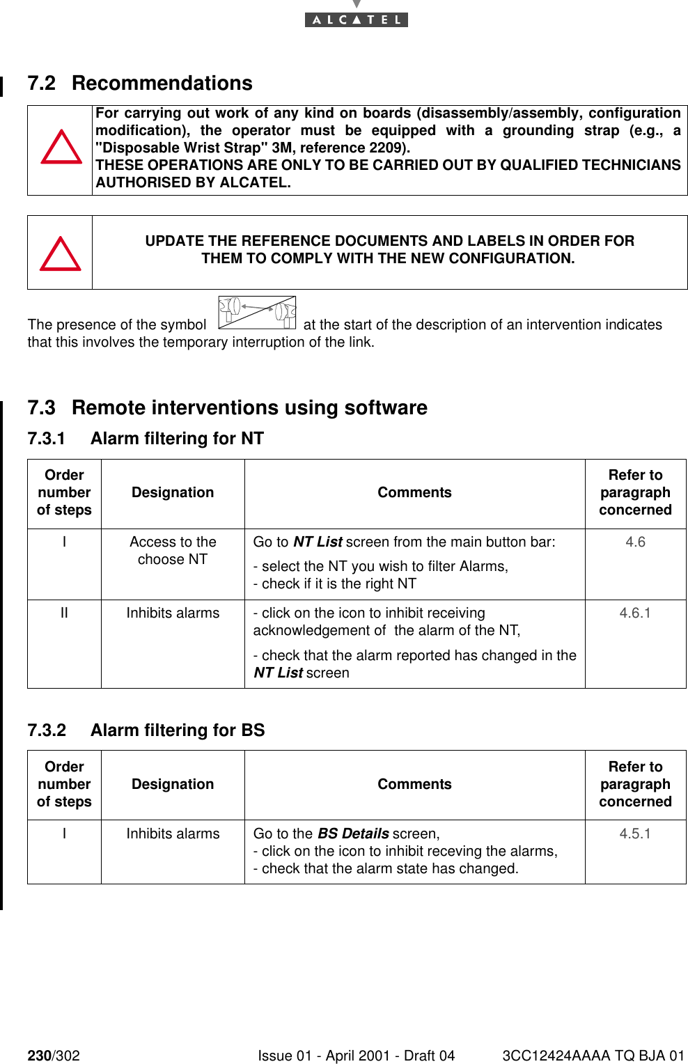
230/302 Issue 01 - April 2001 - Draft 04 3CC12424AAAA TQ BJA 012467.2 RecommendationsThe presence of the symbol   at the start of the description of an intervention indicatesthat this involves the temporary interruption of the link.7.3 Remote interventions using software7.3.1 Alarm filtering for NT7.3.2 Alarm filtering for BSFor carrying out work of any kind on boards (disassembly/assembly, configurationmodification), the operator must be equipped with a grounding strap (e.g., a"Disposable Wrist Strap" 3M, reference 2209).THESE OPERATIONS ARE ONLY TO BE CARRIED OUT BY QUALIFIED TECHNICIANSAUTHORISED BY ALCATEL.UPDATE THE REFERENCE DOCUMENTS AND LABELS IN ORDER FORTHEM TO COMPLY WITH THE NEW CONFIGURATION.Order number of steps Designation Comments Refer to   paragraph concernedI Access to the choose NT Go to NT List screen from the main button bar:- select the NT you wish to filter Alarms,- check if it is the right NT4.6II Inhibits alarms - click on the icon to inhibit receiving acknowledgement of  the alarm of the NT,- check that the alarm reported has changed in theNT List screen4.6.1Order number of steps Designation Comments Refer to   paragraph concernedI Inhibits alarms Go to the BS Details screen,- click on the icon to inhibit receving the alarms, - check that the alarm state has changed.4.5.1
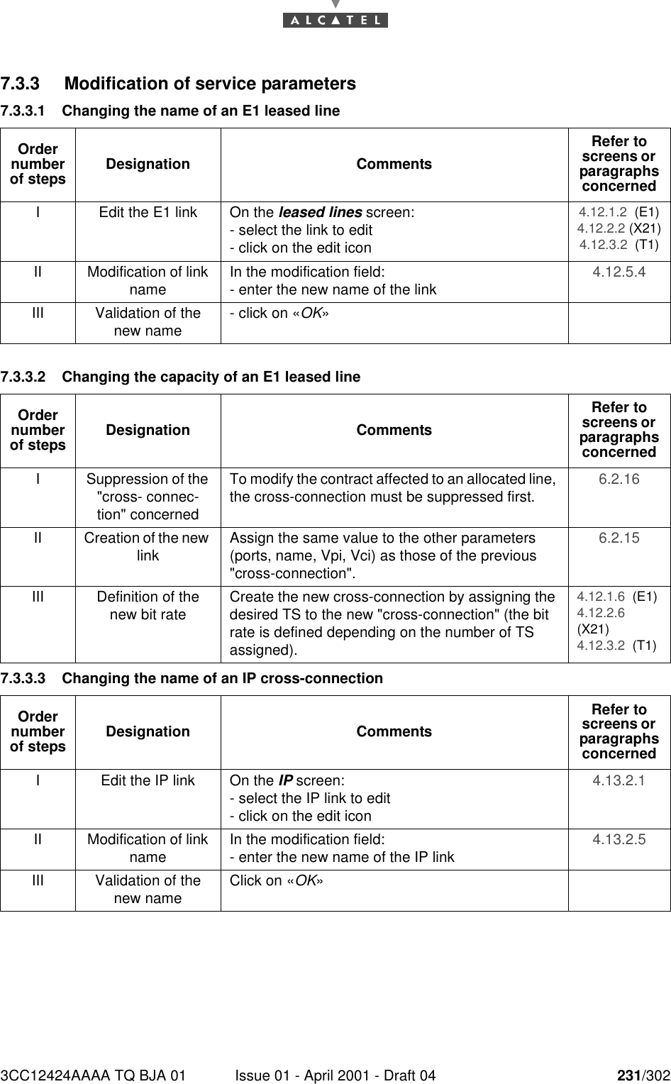
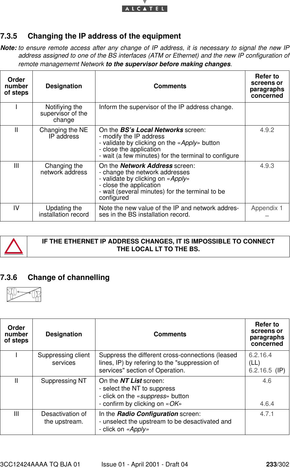
3CC12424AAAA TQ BJA 01 Issue 01 - April 2001 - Draft 04 231/3022467.3.3 Modification of service parameters7.3.3.1 Changing the name of an E1 leased line 7.3.3.2 Changing the capacity of an E1 leased line7.3.3.3 Changing the name of an IP cross-connectionOrder number of steps Designation CommentsRefer to screens or  paragraphs concernedI Edit the E1 link On the leased lines screen:- select the link to edit- click on the edit icon4.12.1.2  (E1)4.12.2.2 (X21)4.12.3.2  (T1)II Modification of link name In the modification field:- enter the new name of the link 4.12.5.4 III Validation of the new name - click on «OK»Order number of steps Designation CommentsRefer to screens or  paragraphs concernedI Suppression of the "cross- connec-tion" concernedTo modify the contract affected to an allocated line, the cross-connection must be suppressed first. 6.2.16 II Creation of the new link Assign the same value to the other parameters (ports, name, Vpi, Vci) as those of the previous "cross-connection".6.2.15 III Definition of the new bit rate Create the new cross-connection by assigning the desired TS to the new "cross-connection" (the bit rate is defined depending on the number of TS assigned).4.12.1.6  (E1)4.12.2.6(X21)4.12.3.2  (T1)Order number of steps Designation CommentsRefer to screens or  paragraphs concernedI Edit the IP link On the IP screen:- select the IP link to edit- click on the edit icon4.13.2.1 II Modification of link name In the modification field:- enter the new name of the IP link 4.13.2.5 III Validation of the new name Click on «OK»
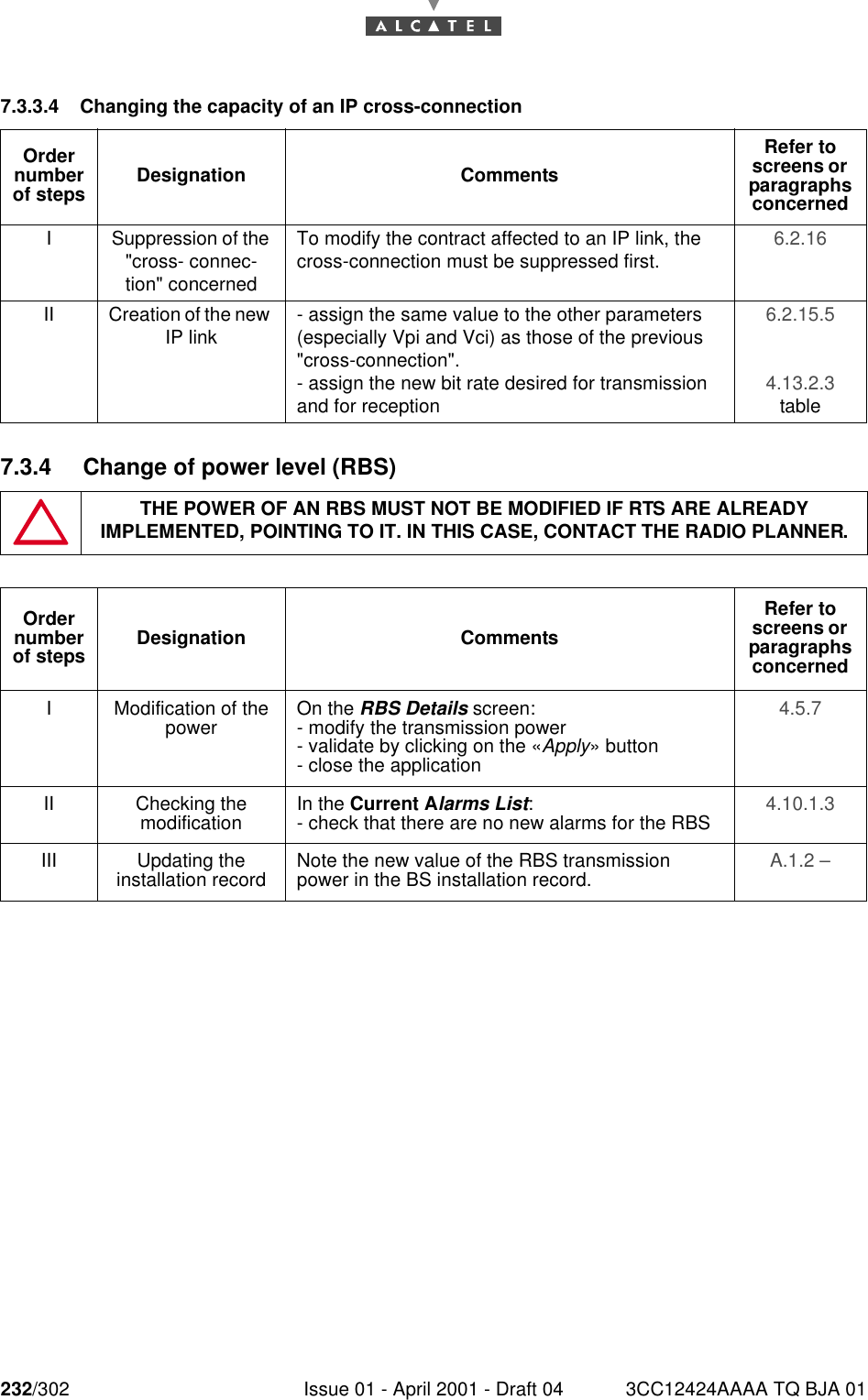
232/302 Issue 01 - April 2001 - Draft 04 3CC12424AAAA TQ BJA 012467.3.3.4 Changing the capacity of an IP cross-connection7.3.4 Change of power level (RBS)Order number of steps Designation CommentsRefer to screens or  paragraphs concernedI Suppression of the "cross- connec-tion" concernedTo modify the contract affected to an IP link, the cross-connection must be suppressed first. 6.2.16 II Creation of the new IP link - assign the same value to the other parameters (especially Vpi and Vci) as those of the previous "cross-connection".- assign the new bit rate desired for transmission and for reception6.2.15.5 4.13.2.3 tableTHE POWER OF AN RBS MUST NOT BE MODIFIED IF RTS ARE ALREADY IMPLEMENTED, POINTING TO IT. IN THIS CASE, CONTACT THE RADIO PLANNER.Order number of steps Designation CommentsRefer to screens or  paragraphs concernedI Modification of the power On the RBS Details screen:- modify the transmission power- validate by clicking on the «Apply» button- close the application4.5.7 II Checking themodification In the Current Alarms List:- check that there are no new alarms for the RBS 4.10.1.3 III Updating theinstallation record Note the new value of the RBS transmission power in the BS installation record. A.1.2 –
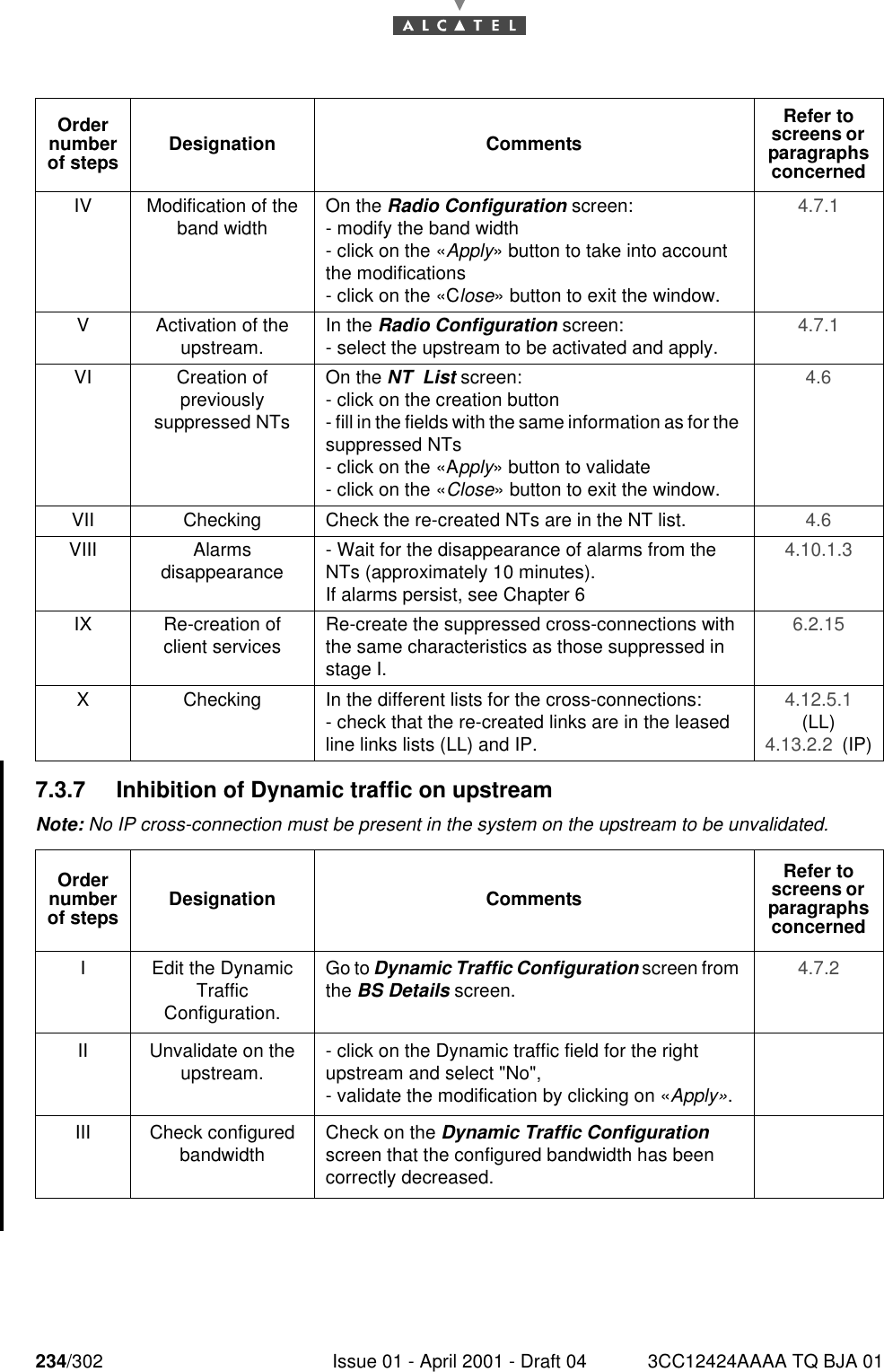
3CC12424AAAA TQ BJA 01 Issue 01 - April 2001 - Draft 04 233/3022467.3.5 Changing the IP address of the equipmentNote: to ensure remote access after any change of IP address, it is necessary to signal the new IPaddress assigned to one of the BS interfaces (ATM or Ethernet) and the new IP configuration ofremote managememt Network to the supervisor before making changes.7.3.6 Change of channellingOrder number of steps Designation CommentsRefer to screens or  paragraphs concernedI Notifiying the supervisor of the changeInform the supervisor of the IP address change.II Changing the NE IP address On the BS’s Local Networks screen:- modify the IP address- validate by clicking on the «Apply» button- close the application- wait (a few minutes) for the terminal to configure4.9.2 III Changing the network address On the Network Address screen:- change the network addresses- validate by clicking on «Apply»- close the application- wait (several minutes) for the terminal to be configured4.9.3 IV Updating theinstallation record Note the new value of the IP and network addres-ses in the BS installation record. Appendix 1 – IF THE ETHERNET IP ADDRESS CHANGES, IT IS IMPOSSIBLE TO CONNECTTHE LOCAL LT TO THE BS.Order number of steps Designation CommentsRefer to screens or  paragraphs concernedI Suppressing client services Suppress the different cross-connections (leased lines, IP) by refering to the "suppression of services" section of Operation.6.2.16.4(LL)6.2.16.5  (IP)II Suppressing NT On the NT List screen:- select the NT to suppress- click on the «suppress» button- confirm by clicking on «OK»4.6 4.6.4 III Desactivation of the upstream. In the Radio Configuration screen:- unselect the upstream to be desactivated and- click on «Apply»4.7.1
234/302 Issue 01 - April 2001 - Draft 04 3CC12424AAAA TQ BJA 012467.3.7 Inhibition of Dynamic traffic on upstreamNote: No IP cross-connection must be present in the system on the upstream to be unvalidated. IV Modification of the band width On the Radio Configuration screen:- modify the band width- click on the «Apply» button to take into account the modifications- click on the «Close» button to exit the window.4.7.1 V Activation of the upstream. In the Radio Configuration screen:- select the upstream to be activated and apply. 4.7.1 VI Creation ofpreviouslysuppressed NTsOn the NT  List screen:- click on the creation button- fill in the fields with the same information as for the suppressed NTs- click on the «Apply» button to validate- click on the «Close» button to exit the window.4.6 VII Checking Check the re-created NTs are in the NT list. 4.6 VIII Alarmsdisappearance - Wait for the disappearance of alarms from the NTs (approximately 10 minutes).If alarms persist, see Chapter 64.10.1.3 IX Re-creation of client services Re-create the suppressed cross-connections with the same characteristics as those suppressed in stage I.6.2.15 X Checking In the different lists for the cross-connections:- check that the re-created links are in the leased line links lists (LL) and IP.4.12.5.1  (LL)4.13.2.2  (IP)Order number of steps Designation CommentsRefer to screens or  paragraphs concernedI Edit the Dynamic TrafficConfiguration.Go to Dynamic Traffic Configuration screen from the BS Details screen. 4.7.2 II Unvalidate on the upstream. - click on the Dynamic traffic field for the right upstream and select "No",- validate the modification by clicking on «Apply».III Check configured bandwidth Check on the Dynamic Traffic Configuration screen that the configured bandwidth has been correctly decreased.Order number of steps Designation CommentsRefer to screens or  paragraphs concerned
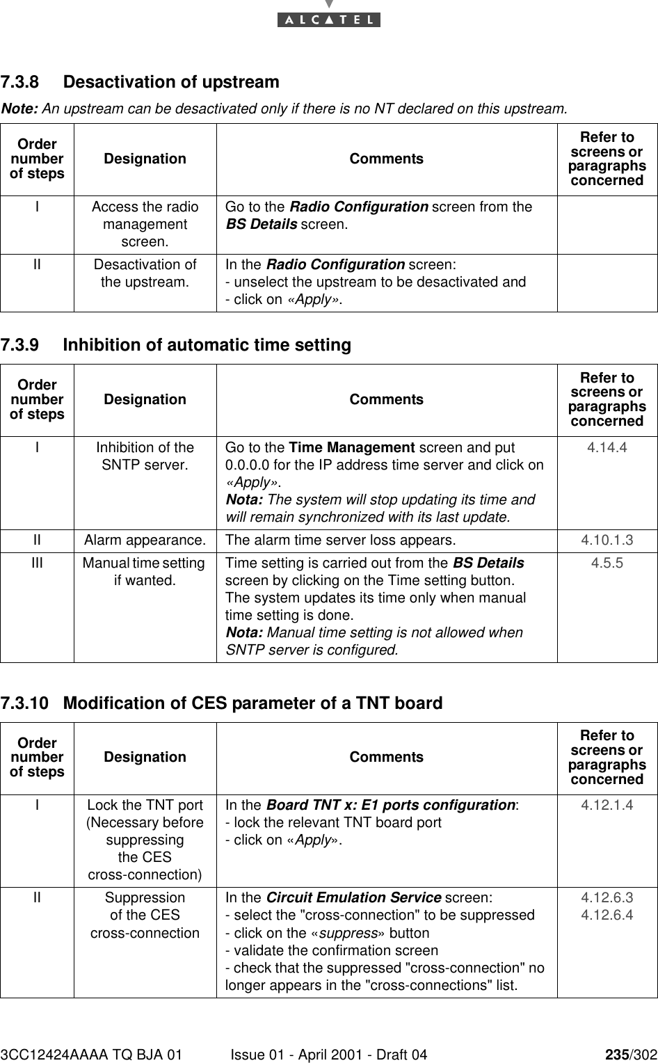
3CC12424AAAA TQ BJA 01 Issue 01 - April 2001 - Draft 04 235/3022467.3.8 Desactivation of upstreamNote: An upstream can be desactivated only if there is no NT declared on this upstream.7.3.9 Inhibition of automatic time setting7.3.10 Modification of CES parameter of a TNT boardOrder number of steps Designation CommentsRefer to screens or  paragraphs concernedI Access the radio management screen.Go to the Radio Configuration screen from the BS Details screen.II Desactivation of the upstream. In the Radio Configuration screen:- unselect the upstream to be desactivated and- click on «Apply».Order number of steps Designation CommentsRefer to screens or  paragraphs concernedI Inhibition of the SNTP server. Go to the Time Management screen and put 0.0.0.0 for the IP address time server and click on «Apply».Nota: The system will stop updating its time and will remain synchronized with its last update.4.14.4 II Alarm appearance. The alarm time server loss appears. 4.10.1.3 III Manual time setting if wanted. Time setting is carried out from the BS Details screen by clicking on the Time setting button.The system updates its time only when manual time setting is done.Nota: Manual time setting is not allowed when SNTP server is configured.4.5.5 Order number of steps Designation CommentsRefer to screens or  paragraphs concernedI Lock the TNT port (Necessary before suppressingthe CEScross-connection)In the Board TNT x: E1 ports configuration:- lock the relevant TNT board port- click on «Apply».4.12.1.4 II Suppressionof the CEScross-connectionIn the Circuit Emulation Service screen:- select the "cross-connection" to be suppressed- click on the «suppress» button- validate the confirmation screen- check that the suppressed "cross-connection" no longer appears in the "cross-connections" list.4.12.6.3 4.12.6.4
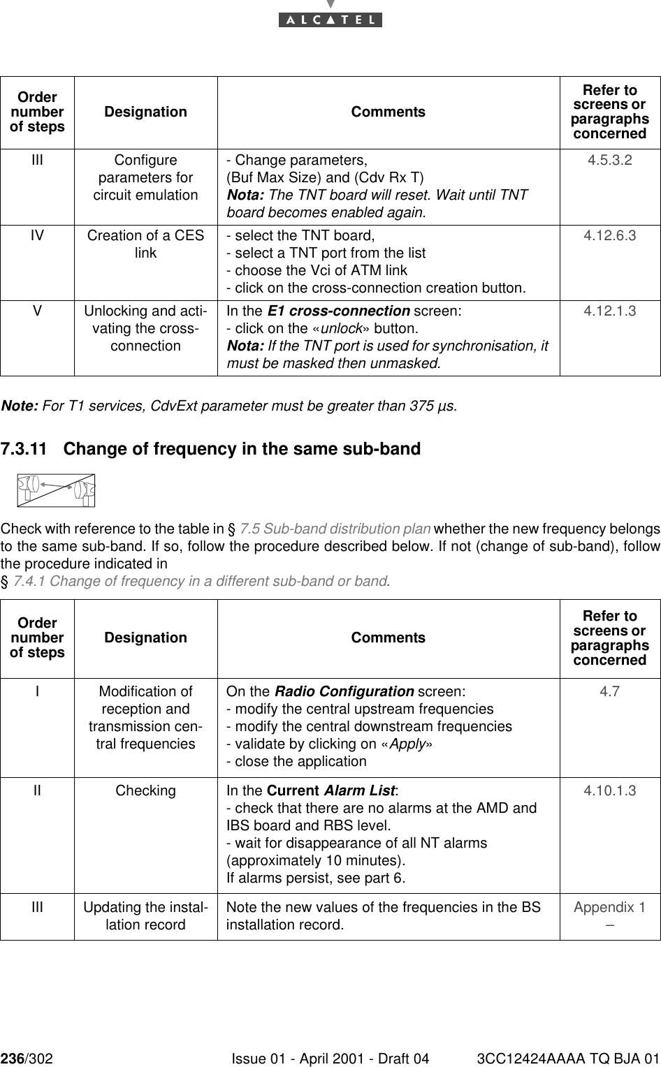
236/302 Issue 01 - April 2001 - Draft 04 3CC12424AAAA TQ BJA 01246Note: For T1 services, CdvExt parameter must be greater than 375 µs.7.3.11 Change of frequency in the same sub-bandCheck with reference to the table in § 7.5 Sub-band distribution plan whether the new frequency belongsto the same sub-band. If so, follow the procedure described below. If not (change of sub-band), followthe procedure indicated in § 7.4.1 Change of frequency in a different sub-band or band.III Configureparameters forcircuit emulation- Change parameters,(Buf Max Size) and (Cdv Rx T)Nota: The TNT board will reset. Wait until TNT board becomes enabled again.4.5.3.2 IV Creation of a CES link - select the TNT board,- select a TNT port from the list- choose the Vci of ATM link- click on the cross-connection creation button.4.12.6.3 V Unlocking and acti-vating the cross-connectionIn the E1 cross-connection screen:- click on the «unlock» button.Nota: If the TNT port is used for synchronisation, it must be masked then unmasked.4.12.1.3 Order number of steps Designation CommentsRefer to screens or  paragraphs concernedI Modification of reception and transmission cen-tral frequenciesOn the Radio Configuration screen:- modify the central upstream frequencies- modify the central downstream frequencies- validate by clicking on «Apply»- close the application4.7 II Checking In the Current Alarm List:- check that there are no alarms at the AMD and IBS board and RBS level.- wait for disappearance of all NT alarms (approximately 10 minutes). If alarms persist, see part 6.4.10.1.3 III Updating the instal-lation record Note the new values of the frequencies in the BS installation record. Appendix 1 – Order number of steps Designation CommentsRefer to screens or  paragraphs concerned
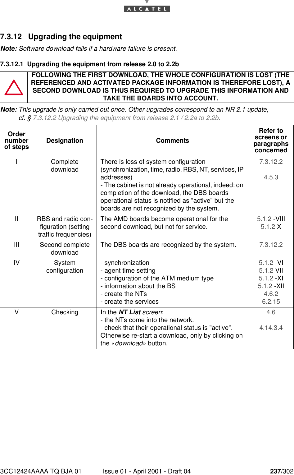
3CC12424AAAA TQ BJA 01 Issue 01 - April 2001 - Draft 04 237/3022467.3.12 Upgrading the equipmentNote: Software download fails if a hardware failure is present.7.3.12.1 Upgrading the equipment from release 2.0 to 2.2bNote: This upgrade is only carried out once. Other upgrades correspond to an NR 2.1 update, cf. § 7.3.12.2 Upgrading the equipment from release 2.1 / 2.2a to 2.2b.FOLLOWING THE FIRST DOWNLOAD, THE WHOLE CONFIGURATION IS LOST (THE REFERENCED AND ACTIVATED PACKAGE INFORMATION IS THEREFORE LOST), A SECOND DOWNLOAD IS THUS REQUIRED TO UPGRADE THIS INFORMATION AND TAKE THE BOARDS INTO ACCOUNT.Order number of steps Designation CommentsRefer to screens or  paragraphs concernedI Completedownload There is loss of system configuration (synchronization, time, radio, RBS, NT, services, IP addresses)- The cabinet is not already operational, indeed: on completion of the download, the DBS boards operational status is notified as "active" but the boards are not recognized by the system.7.3.12.2 4.5.3 II RBS and radio con-figuration (setting traffic frequencies)The AMD boards become operational for the second download, but not for service. 5.1.2 -VIII5.1.2 XIII Second complete download The DBS boards are recognized by the system. 7.3.12.2 IV Systemconfiguration - synchronization- agent time setting- configuration of the ATM medium type- information about the BS- create the NTs- create the services5.1.2 -VI5.1.2 VII5.1.2 -XI5.1.2 -XII4.6.2 6.2.15 V Checking In the NT List screen:- the NTs come into the network.- check that their operational status is "active".Otherwise re-start a download, only by clicking on the «download» button.4.6 4.14.3.4
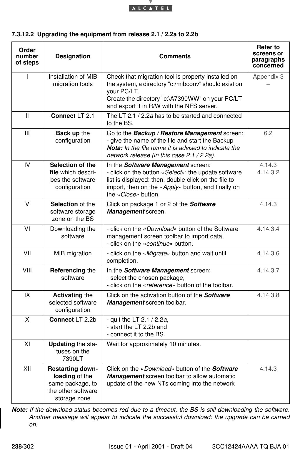
238/302 Issue 01 - April 2001 - Draft 04 3CC12424AAAA TQ BJA 012467.3.12.2 Upgrading the equipment from release 2.1 / 2.2a to 2.2bNote: If the download status becomes red due to a timeout, the BS is still downloading the software.Another message will appear to indicate the successful download: the upgrade can be carriedon.Order number of steps Designation CommentsRefer to screens or  paragraphs concernedI Installation of MIB migration tools Check that migration tool is property installed on the system, a directory "c:\mibconv" should exist on your PC/LT.Create the directory "c:\A7390WW" on your PC/LT and export it in R/W with the NFS server.Appendix 3 – II Connect LT 2.1 The LT 2.1 / 2.2a has to be started and connected to the BS.III Back up theconfiguration Go to the Backup / Restore Management screen:- give the name of the file and start the BackupNota: In the file name it is advised to indicate the network release (in this case 2.1 / 2.2a).6.2 IV Selection of the file which descri-bes the software configurationIn the Software Management screen:- click on the button «Select»: the update software list is displayed: then, double-click on the file to import, then on the «Apply» button, and finally on the «Close» button.4.14.3 4.14.3.2 VSelection of the software storage zone on the BSClick on package 1 or 2 of the Software Management screen. 4.14.3 VI Downloading the software - click on the «Download» button of the Software management screen toolbar to import data,- click on the «continue» button.4.14.3.4 VII MIB migration - click on the «Migrate» button and wait until completion. 4.14.3.6 VIII Referencing the software In the Software Management screen:- select the chosen package,- click on the «reference» button of the toolbar.4.14.3.7 IX Activating the selected software configurationClick on the activation button of the Software Management screen toolbar. 4.14.3.8 XConnect LT 2.2b - quit the LT 2.1 / 2.2a,- start the LT 2.2b and- connect it to the BS.XI Updating the sta-tuses on the 7390LTWait for approximately 10 minutes.XII Restarting down-loading of the same package, to the other software storage zoneClick on the «Download» button of the Software Management screen toolbar to allow automatic update of the new NTs coming into the network4.14.3
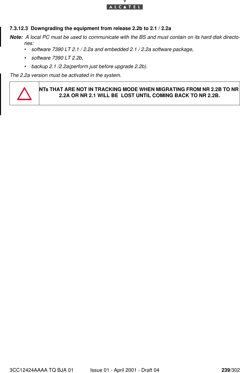
3CC12424AAAA TQ BJA 01 Issue 01 - April 2001 - Draft 04 239/3022467.3.12.3 Downgrading the equipment from release 2.2b to 2.1 / 2.2aNote:  A local PC must be used to communicate with the BS and must contain on its hard disk directo-ries:•software 7390 LT 2.1 / 2.2a and embedded 2.1 / 2.2a software package,•software 7390 LT 2.2b,•backup 2.1 /2.2a(perform just before upgrade 2.2b).The 2.2a version must be activated in the system.NTs THAT ARE NOT IN TRACKING MODE WHEN MIGRATING FROM NR 2.2B TO NR 2.2A OR NR 2.1 WILL BE  LOST UNTIL COMING BACK TO NR 2.2B.
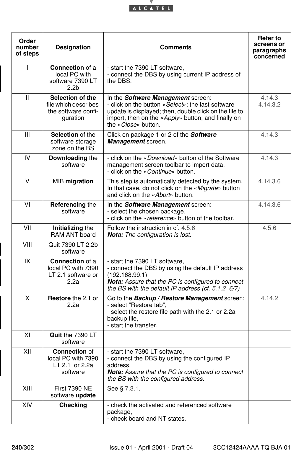
240/302 Issue 01 - April 2001 - Draft 04 3CC12424AAAA TQ BJA 01246Order number of steps Designation CommentsRefer to screens or  paragraphs concernedIConnection of a local PC with software 7390 LT 2.2b- start the 7390 LT software,- connect the DBS by using current IP address of the DBS.II Selection of the file which describes the software confi-gurationIn the Software Management screen:- click on the button «Select»; the last software update is displayed; then, double click on the file to import, then on the «Apply» button, and finally on the «Close» button.4.14.3 4.14.3.2 III Selection of the software storage zone on the BSClick on package 1 or 2 of the Software Management screen. 4.14.3 IV Downloading the software - click on the «Download» button of the Software management screen toolbar to import data.- click on the «Continue» button.4.14.3 VMIB migration This step is automatically detected by the system.In that case, do not click on the «Migrate» button and click on the «Abort» button.4.14.3.6 VI Referencing the software In the Software Management screen:- select the chosen package,- click on the «reference» button of the toolbar.4.14.3.6 VII Initializing the RAM ANT board Follow the instruction in cf. 4.5.6 Nota: The configuration is lost. 4.5.6 VIII Quit 7390 LT 2.2b softwareIX Connection of a local PC with 7390 LT 2.1 software or 2.2a- start the 7390 LT software,- connect the DBS by using the default IP address (192.168.99.1)Nota: Assure that the PC is configured to connect the BS with the default IP address (cf. 5.1.2  6/7)XRestore the 2.1 or 2.2a Go to the Backup / Restore Management screen:- select "Restore tab",- select the restore file path with the 2.1 or 2.2a backup file,- start the transfer.4.14.2 XI Quit the 7390 LT softwareXII Connection of local PC with 7390 LT 2.1  or 2.2a software- start the 7390 LT software,- connect the DBS by using the configured IP address.Nota: Assure that the PC is configured to connect the BS with the configured address.XIII First 7390 NE software update See § 7.3.1.XIV Checking - check the activated and referenced software package,- check board and NT states.
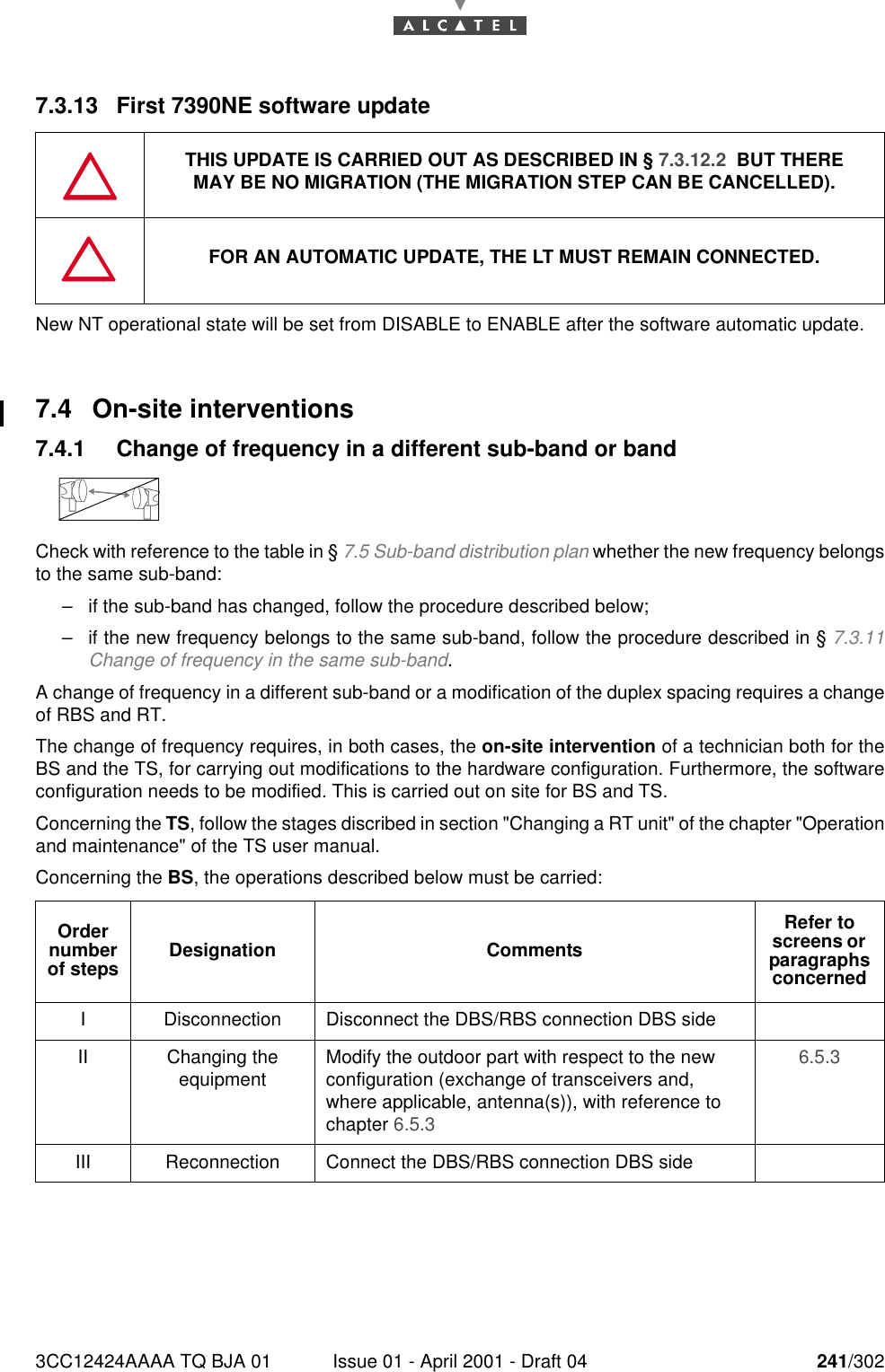
3CC12424AAAA TQ BJA 01 Issue 01 - April 2001 - Draft 04 241/3022467.3.13 First 7390NE software updateNew NT operational state will be set from DISABLE to ENABLE after the software automatic update.7.4 On-site interventions7.4.1 Change of frequency in a different sub-band or bandCheck with reference to the table in § 7.5 Sub-band distribution plan whether the new frequency belongsto the same sub-band:–if the sub-band has changed, follow the procedure described below;–if the new frequency belongs to the same sub-band, follow the procedure described in § 7.3.11Change of frequency in the same sub-band.A change of frequency in a different sub-band or a modification of the duplex spacing requires a changeof RBS and RT.The change of frequency requires, in both cases, the on-site intervention of a technician both for theBS and the TS, for carrying out modifications to the hardware configuration. Furthermore, the softwareconfiguration needs to be modified. This is carried out on site for BS and TS.Concerning the TS, follow the stages discribed in section "Changing a RT unit" of the chapter "Operationand maintenance" of the TS user manual.Concerning the BS, the operations described below must be carried:THIS UPDATE IS CARRIED OUT AS DESCRIBED IN § 7.3.12.2  BUT THEREMAY BE NO MIGRATION (THE MIGRATION STEP CAN BE CANCELLED).FOR AN AUTOMATIC UPDATE, THE LT MUST REMAIN CONNECTED.Order number of steps Designation CommentsRefer to screens or  paragraphs concernedI Disconnection Disconnect the DBS/RBS connection DBS sideII Changing theequipment Modify the outdoor part with respect to the new configuration (exchange of transceivers and, where applicable, antenna(s)), with reference to chapter 6.5.3 6.5.3 III Reconnection Connect the DBS/RBS connection DBS side
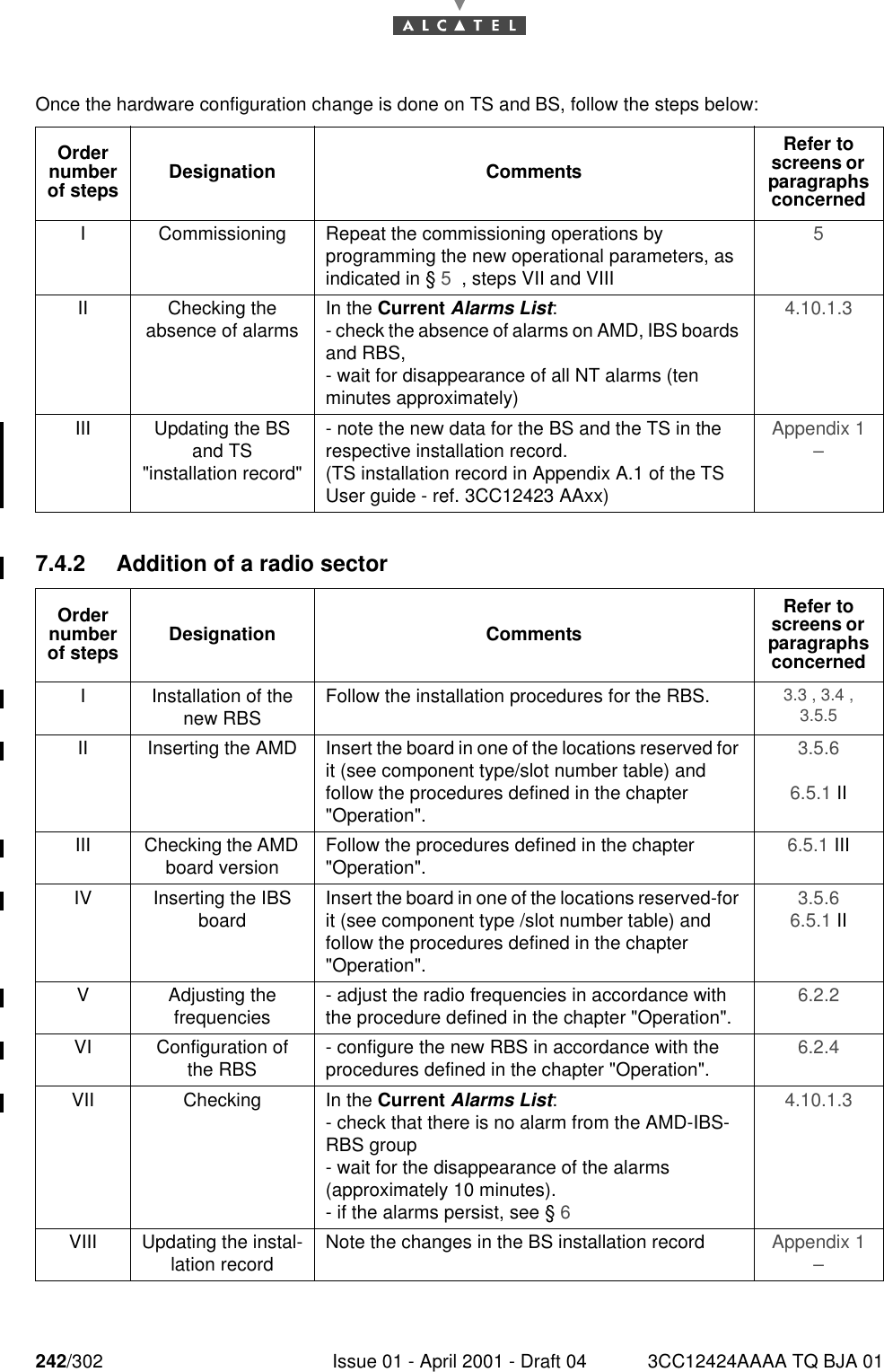
242/302 Issue 01 - April 2001 - Draft 04 3CC12424AAAA TQ BJA 01246Once the hardware configuration change is done on TS and BS, follow the steps below:7.4.2 Addition of a radio sectorOrder number of steps Designation CommentsRefer to screens or  paragraphs concernedI Commissioning Repeat the commissioning operations by programming the new operational parameters, as indicated in § 5  , steps VII and VIII5 II Checking the absence of alarms In the Current Alarms List:- check the absence of alarms on AMD, IBS boards and RBS,- wait for disappearance of all NT alarms (ten minutes approximately)4.10.1.3 III Updating the BS and TS"installation record"- note the new data for the BS and the TS in the respective installation record.(TS installation record in Appendix A.1 of the TS User guide - ref. 3CC12423 AAxx)Appendix 1 – Order number of steps Designation CommentsRefer to screens or  paragraphs concernedI Installation of the new RBS Follow the installation procedures for the RBS. 3.3 , 3.4 , 3.5.5 II Inserting the AMD Insert the board in one of the locations reserved for it (see component type/slot number table) and follow the procedures defined in the chapter "Operation".3.5.6 6.5.1 IIIII Checking the AMD board version Follow the procedures defined in the chapter "Operation". 6.5.1 IIIIV Inserting the IBS board Insert the board in one of the locations reserved-for it (see component type /slot number table) and follow the procedures defined in the chapter "Operation".3.5.6 6.5.1 IIV Adjusting thefrequencies - adjust the radio frequencies in accordance with the procedure defined in the chapter "Operation". 6.2.2 VI Configuration of the RBS - configure the new RBS in accordance with the procedures defined in the chapter "Operation". 6.2.4 VII Checking In the Current Alarms List:- check that there is no alarm from the AMD-IBS-RBS group- wait for the disappearance of the alarms (approximately 10 minutes).- if the alarms persist, see § 64.10.1.3 VIII Updating the instal-lation record Note the changes in the BS installation record  Appendix 1 –
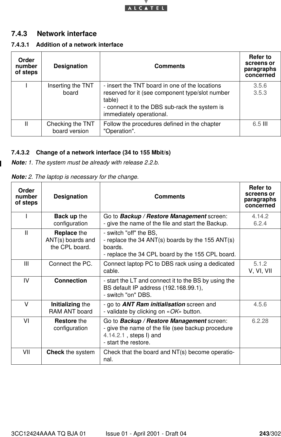
3CC12424AAAA TQ BJA 01 Issue 01 - April 2001 - Draft 04 243/3022467.4.3 Network interface7.4.3.1 Addition of a network interface7.4.3.2 Change of a network interface (34 to 155 Mbit/s)Note: 1. The system must be already with release 2.2.b.Note: 2. The laptop is necessary for the change.Order number of steps Designation CommentsRefer to screens or  paragraphs concernedI Inserting the TNT board - insert the TNT board in one of the locations reserved for it (see component type/slot number table)- connect it to the DBS sub-rack the system is immediately operational.3.5.6 3.5.3 II Checking the TNT board version Follow the procedures defined in the chapter "Operation". 6.5 IIIOrder number of steps Designation CommentsRefer to screens or  paragraphs concernedIBack up theconfiguration Go to Backup / Restore Management screen:- give the name of the file and start the Backup. 4.14.2 6.2.4 II Replace the ANT(s) boards and the CPL board.- switch "off" the BS,- replace the 34 ANT(s) boards by the 155 ANT(s) boards.- replace the 34 CPL board by the 155 CPL board.III Connect the PC. Connect laptop PC to DBS rack using a dedicated cable. 5.1.2 V, VI, VIIIV Connection - start the LT and connect it to the BS by using the BS default IP address (192.168.99.1),- switch "on" DBS.VInitializing the RAM ANT board - go to ANT Ram initialisation screen and- validate by clicking on «OK» button. 4.5.6 VI Restore theconfiguration Go to Backup / Restore Management screen:- give the name of the file (see backup procedure 4.14.2.1 , steps I) and- start the restore.6.2.28 VII Check the system Check that the board and NT(s) become operatio-nal.
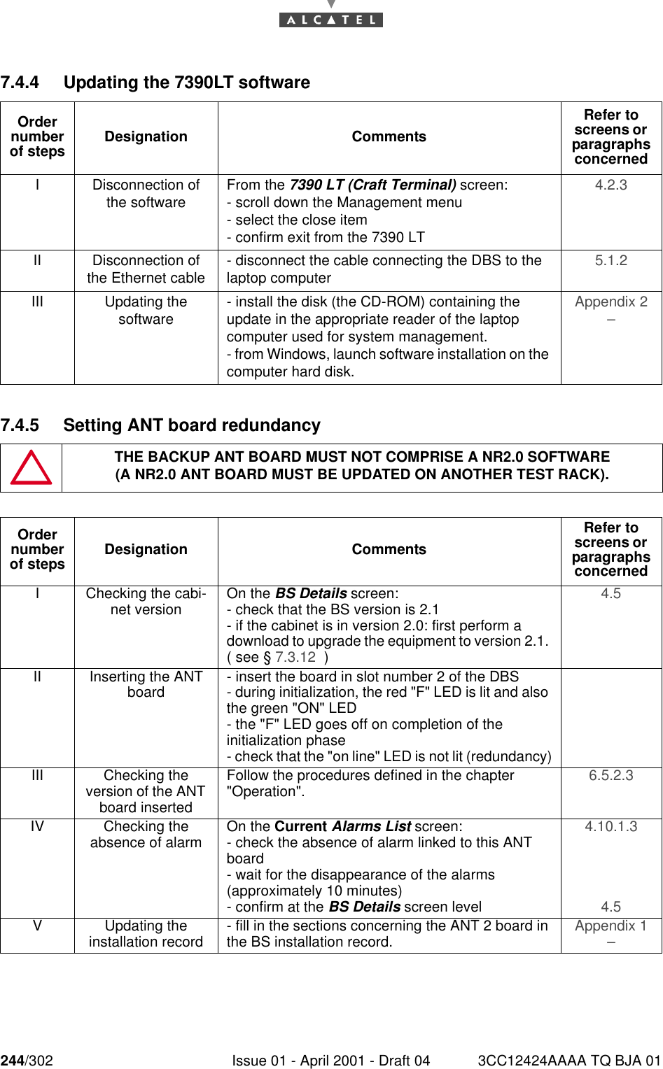
244/302 Issue 01 - April 2001 - Draft 04 3CC12424AAAA TQ BJA 012467.4.4 Updating the 7390LT software7.4.5 Setting ANT board redundancyOrder number of steps Designation CommentsRefer to screens or  paragraphs concernedI Disconnection of the software From the 7390 LT (Craft Terminal) screen:- scroll down the Management menu- select the close item- confirm exit from the 7390 LT4.2.3 II Disconnection of the Ethernet cable - disconnect the cable connecting the DBS to the laptop computer 5.1.2 III Updating the software - install the disk (the CD-ROM) containing the update in the appropriate reader of the laptop computer used for system management.- from Windows, launch software installation on the computer hard disk.Appendix 2 – THE BACKUP ANT BOARD MUST NOT COMPRISE A NR2.0 SOFTWARE(A NR2.0 ANT BOARD MUST BE UPDATED ON ANOTHER TEST RACK).Order number of steps Designation CommentsRefer to screens or  paragraphs concernedI Checking the cabi-net version On the BS Details screen:- check that the BS version is 2.1- if the cabinet is in version 2.0: first perform a download to upgrade the equipment to version 2.1. ( see § 7.3.12  )4.5 II Inserting the ANT board - insert the board in slot number 2 of the DBS- during initialization, the red "F" LED is lit and also the green "ON" LED- the "F" LED goes off on completion of the initialization phase- check that the "on line" LED is not lit (redundancy)III Checking theversion of the ANT board insertedFollow the procedures defined in the chapter "Operation". 6.5.2.3 IV Checking the absence of alarm On the Current Alarms List screen:- check the absence of alarm linked to this ANT board- wait for the disappearance of the alarms (approximately 10 minutes)- confirm at the BS Details screen level4.10.1.3 4.5 V Updating theinstallation record - fill in the sections concerning the ANT 2 board in the BS installation record. Appendix 1 –
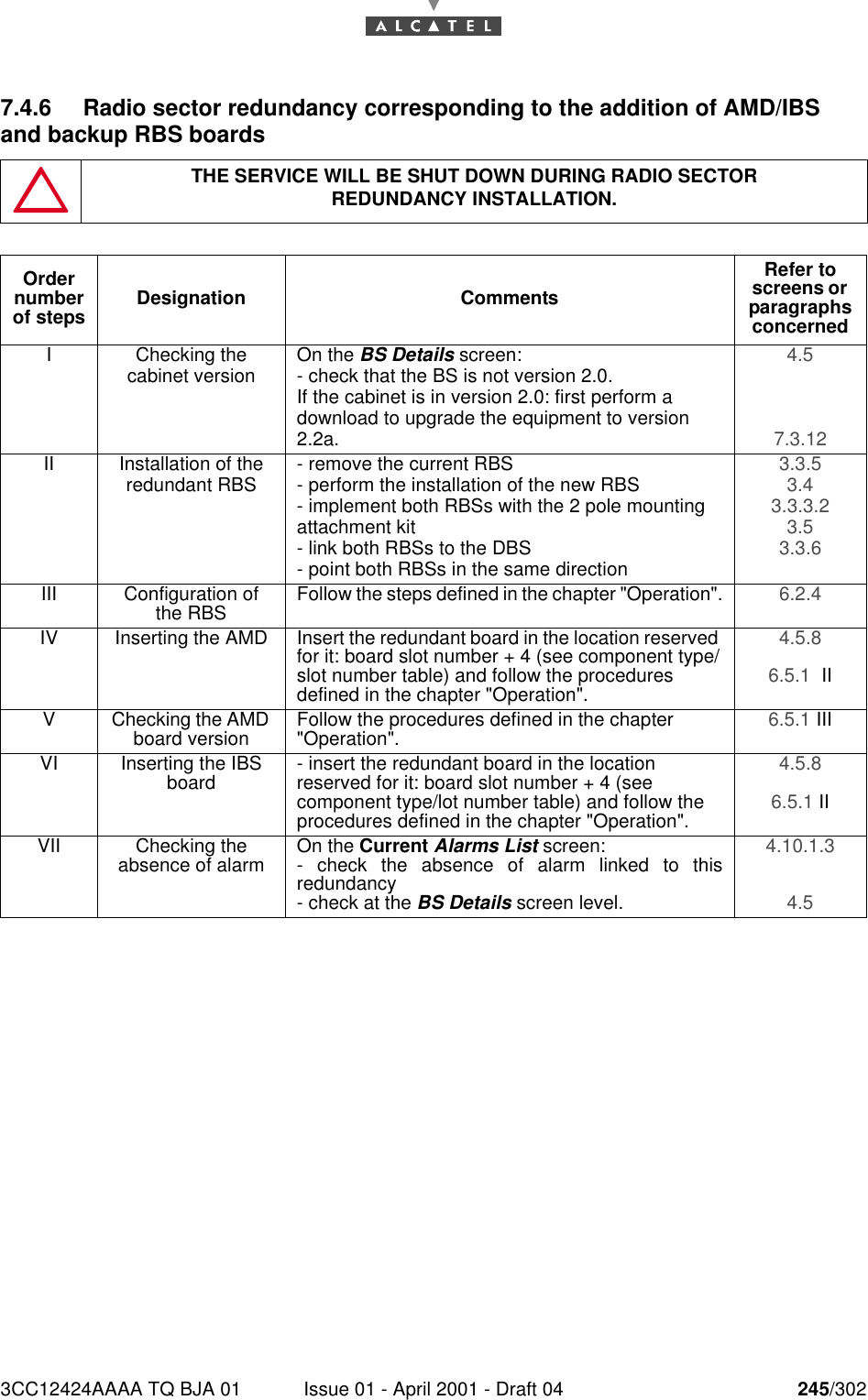
3CC12424AAAA TQ BJA 01 Issue 01 - April 2001 - Draft 04 245/3022467.4.6 Radio sector redundancy corresponding to the addition of AMD/IBS and backup RBS boardsTHE SERVICE WILL BE SHUT DOWN DURING RADIO SECTORREDUNDANCY INSTALLATION.Order number of steps Designation CommentsRefer to screens or  paragraphs concernedI Checking thecabinet version On the BS Details screen:- check that the BS is not version 2.0.If the cabinet is in version 2.0: first perform a download to upgrade the equipment to version 2.2a.4.5 7.3.12 II Installation of the redundant RBS - remove the current RBS- perform the installation of the new RBS- implement both RBSs with the 2 pole mounting attachment kit- link both RBSs to the DBS- point both RBSs in the same direction3.3.5 3.4 3.3.3.2 3.5 3.3.6 III Configuration of the RBS Follow the steps defined in the chapter "Operation". 6.2.4 IV Inserting the AMD Insert the redundant board in the location reserved for it: board slot number + 4 (see component type/slot number table) and follow the procedures defined in the chapter "Operation".4.5.8 6.5.1  IIV Checking the AMD board version Follow the procedures defined in the chapter "Operation". 6.5.1 IIIVI Inserting the IBS board - insert the redundant board in the location reserved for it: board slot number + 4 (see component type/lot number table) and follow the procedures defined in the chapter "Operation".4.5.8 6.5.1 IIVII Checking the absence of alarm On the Current Alarms List screen:- check the absence of alarm linked to thisredundancy- check at the BS Details screen level.4.10.1.3 4.5
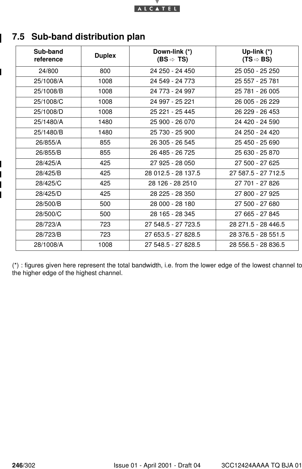
246/302 Issue 01 - April 2001 - Draft 04 3CC12424AAAA TQ BJA 012467.5 Sub-band distribution plan   (*) : figures given here represent the total bandwidth, i.e. from the lower edge of the lowest channel tothe higher edge of the highest channel.Sub-band reference Duplex Down-link (*)(BS *TS) Up-link (*)(TS  BS)24/800 800 24 250 - 24 450 25 050 - 25 25025/1008/A 1008 24 549 - 24 773 25 557 - 25 78125/1008/B 1008 24 773 - 24 997 25 781 - 26 00525/1008/C 1008 24 997 - 25 221 26 005 - 26 22925/1008/D 1008 25 221 - 25 445 26 229 - 26 45325/1480/A 1480 25 900 - 26 070 24 420 - 24 59025/1480/B 1480 25 730 - 25 900 24 250 - 24 42026/855/A 855 26 305 - 26 545 25 450 - 25 69026/855/B 855 26 485 - 26 725 25 630 - 25 87028/425/A 425 27 925 - 28 050 27 500 - 27 62528/425/B 425 28 012.5 - 28 137.5 27 587.5 - 27 712.528/425/C 425 28 126 - 28 2510 27 701 - 27 82628/425/D 425 28 225 - 28 350 27 800 - 27 92528/500/B 500 28 000 - 28 180 27 500 - 27 68028/500/C 500 28 165 - 28 345 27 665 - 27 84528/723/A 723 27 548.5 - 27 723.5 28 271.5 - 28 446.528/723/B 723 27 653.5 - 27 828.5 28 376.5 - 28 551.528/1008/A 1008 27 548.5 - 27 828.5 28 556.5 - 28 836.5

Navigation menu