Alcatel Canada 24T28A01D22C 7390 24 GHz Co-Pol RBS User Manual BS Manual pages 183 to 190

Alcatel Canada Inc 7390 24 GHz Co-Pol RBS BS Manual pages 183 to 190

BS Manual pages 183 to 190

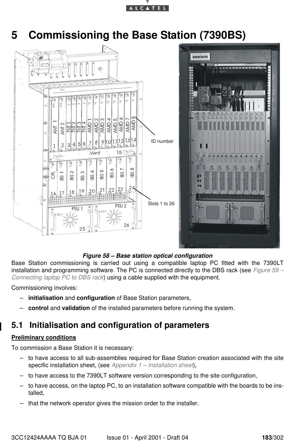
3CC12424AAAA TQ BJA 01 Issue 01 - April 2001 - Draft 04 183/3021905 Commissioning the Base Station (7390BS)Figure 58 – Base station optical configurationBase Station commissioning is carried out using a compatible laptop PC fitted with the 7390LTinstallation and programming software. The PC is connected directly to the DBS rack (see Figure 59 –Connecting laptop PC to DBS rack) using a cable supplied with the equipment.Commissioning involves:–initialisation and configuration of Base Station parameters,–control and validation of the installed parameters before running the system.5.1 Initialisation and configuration of parametersPreliminary conditionsTo commission a Base Station it is necessary:–to have access to all sub-assemblies required for Base Station creation associated with the sitespecific installation sheet, (see Appendix 1 – Installation sheet),–to have access to the 7390LT software version corresponding to the site configuration,–to have access, on the laptop PC, to an installation software compatible with the boards to be ins-talled,–that the network operator gives the mission order to the installer.Slots 1 to 26ID number
184/302 Issue 01 - April 2001 - Draft 04 3CC12424AAAA TQ BJA 01190Main stepsTo commission a Base Station it is necessary to carry out the following:–installation of the DBS rack (see Chapter 3.5 Base Station equipment installation),–installation and configuration of the associated RBS(s) (see Chapter 3 Installation of the Base Sta-tion),–configuration and commissioning of the station using the 7390LT.5.1.1 Equipment requiredTo configure the Base Station parameters the following equipment is required:–the RBS transceivers already installed outdoors, connected to the DBS,–a 50 ohm N/N connector coaxial cable (ref. 3CC07568Axxx) or equivalent.–the DBS rack assembly,–a laptop PC equipped with:•the 7390LT Base Station initialisation and programming software, (see Appendix 2 – Installa-tion of 7390LT software),•the Windows NT4 SP5 Workstation system,•the data transfer application (OMNI NFS).The minimum PC specifications are as follows:–microprocessor: Pentium II 450 MHz,–RAM: 128 MB,–Hard disk: min. 10 GB,–Graphics board: 8 MB,–3" 1/2 floppy drive (internal or external),–12x CD drive (internal or external),–ports: 1 available serial (DB9) and 1 available parallel (centronix) port,–mouse: 2 buttons (PS2 series) or tracking device,–network board: Ethernet 10/100BT (RJ45),–12" monitor (1024x768).
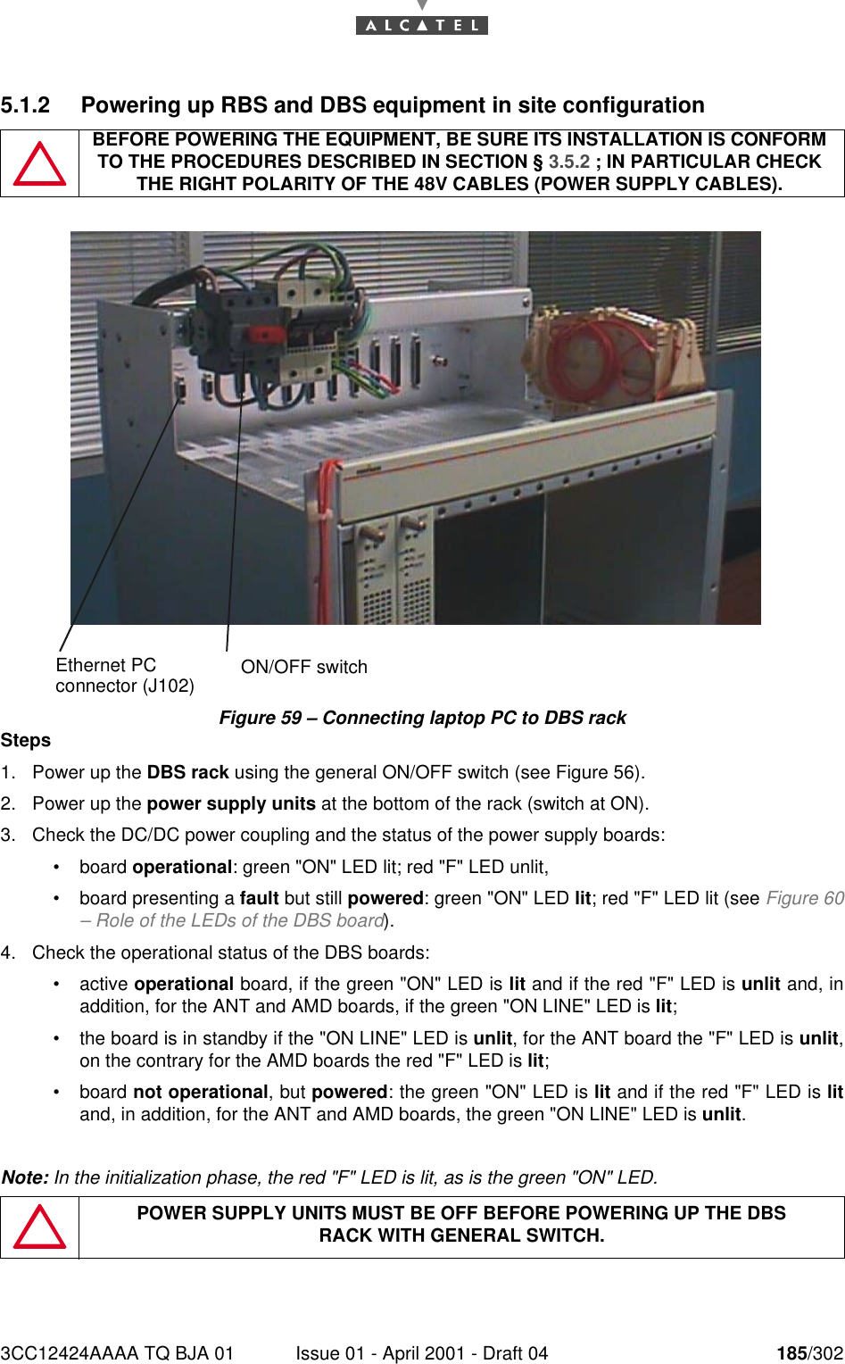
3CC12424AAAA TQ BJA 01 Issue 01 - April 2001 - Draft 04 185/3021905.1.2 Powering up RBS and DBS equipment in site configurationFigure 59 – Connecting laptop PC to DBS rackSteps1. Power up the DBS rack using the general ON/OFF switch (see Figure 56).2. Power up the power supply units at the bottom of the rack (switch at ON).3. Check the DC/DC power coupling and the status of the power supply boards:•board operational: green "ON" LED lit; red "F" LED unlit,•board presenting a fault but still powered: green "ON" LED lit; red "F" LED lit (see Figure 60– Role of the LEDs of the DBS board).4. Check the operational status of the DBS boards:•active operational board, if the green "ON" LED is lit and if the red "F" LED is unlit and, inaddition, for the ANT and AMD boards, if the green "ON LINE" LED is lit;•the board is in standby if the "ON LINE" LED is unlit, for the ANT board the "F" LED is unlit,on the contrary for the AMD boards the red "F" LED is lit;•board not operational, but powered: the green "ON" LED is lit and if the red "F" LED is litand, in addition, for the ANT and AMD boards, the green "ON LINE" LED is unlit.Note: In the initialization phase, the red "F" LED is lit, as is the green "ON" LED.BEFORE POWERING THE EQUIPMENT, BE SURE ITS INSTALLATION IS CONFORM TO THE PROCEDURES DESCRIBED IN SECTION § 3.5.2 ; IN PARTICULAR CHECK THE RIGHT POLARITY OF THE 48V CABLES (POWER SUPPLY CABLES).POWER SUPPLY UNITS MUST BE OFF BEFORE POWERING UP THE DBSRACK WITH GENERAL SWITCH.ON/OFF switchEthernet PCconnector (J102)
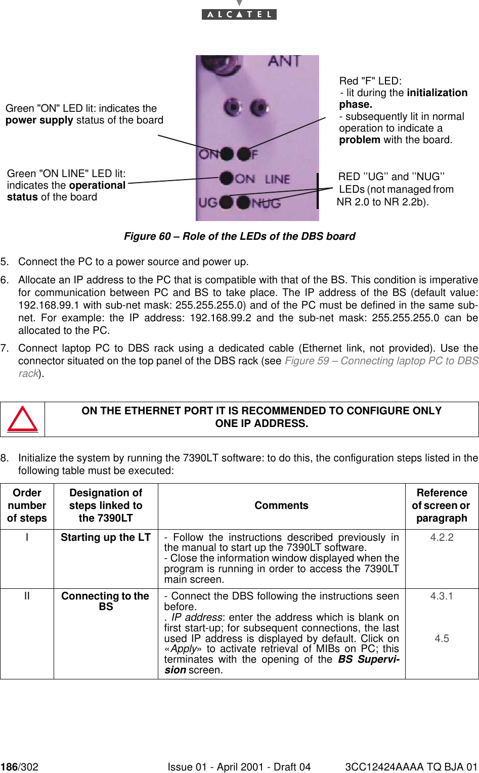
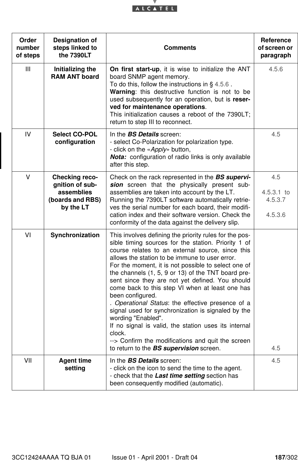
186/302 Issue 01 - April 2001 - Draft 04 3CC12424AAAA TQ BJA 01190Figure 60 – Role of the LEDs of the DBS board5. Connect the PC to a power source and power up.6. Allocate an IP address to the PC that is compatible with that of the BS. This condition is imperativefor communication between PC and BS to take place. The IP address of the BS (default value:192.168.99.1 with sub-net mask: 255.255.255.0) and of the PC must be defined in the same sub-net. For example: the IP address: 192.168.99.2 and the sub-net mask: 255.255.255.0 can beallocated to the PC.7. Connect laptop PC to DBS rack using a dedicated cable (Ethernet link, not provided). Use theconnector situated on the top panel of the DBS rack (see Figure 59 – Connecting laptop PC to DBSrack).8. Initialize the system by running the 7390LT software: to do this, the configuration steps listed in thefollowing table must be executed:ON THE ETHERNET PORT IT IS RECOMMENDED TO CONFIGURE ONLYONE IP ADDRESS.Order number of stepsDesignation of steps linked to the 7390LT Comments Reference of screen or paragraphIStarting up the LT - Follow the instructions described previously inthe manual to start up the 7390LT software.- Close the information window displayed when theprogram is running in order to access the 7390LTmain screen.4.2.2 II Connecting to the BS - Connect the DBS following the instructions seenbefore.. IP address: enter the address which is blank onfirst start-up; for subsequent connections, the lastused IP address is displayed by default. Click on«Apply» to activate retrieval of MIBs on PC; thisterminates with the opening of the BS Supervi-sion screen.4.3.1 4.5 Green "ON" LED lit: indicates thepower supply status of the boardGreen "ON LINE" LED lit:indicates the operationalstatus of the boardRed "F" LED:- lit during the initializationphase.- subsequently lit in normaloperation to indicate aproblem with the board.RED ’’UG’’ and ’’NUG’’ LEDs (not managed from NR 2.0 to NR 2.2b).
3CC12424AAAA TQ BJA 01 Issue 01 - April 2001 - Draft 04 187/302190Order number of stepsDesignation of steps linked to the 7390LT Comments Reference of screen or paragraphIII Initializing the RAM ANT board On first start-up, it is wise to initialize the ANTboard SNMP agent memory.To do this, follow the instructions in § 4.5.6 .Warning: this destructive function is not to beused subsequently for an operation, but is reser-ved for maintenance operations.This initialization causes a reboot of the 7390LT;return to step III to reconnect.4.5.6 IV Select CO-POL configuration In the BS Details screen:- select Co-Polarization for polarization type.- click on the «Apply» button,Nota:  configuration of radio links is only availableafter this step.4.5 VChecking reco-gnition of sub-assemblies (boards and RBS) by the LTCheck on the rack represented in the BS supervi-sion screen that the physically present sub-assemblies are taken into account by the LT.Running the 7390LT software automatically retrie-ves the serial number for each board, their modifi-cation index and their software version. Check theconformity of the data against the delivery slip.4.5 4.5.3.1  to 4.5.3.7 4.5.3.6 VI Synchronization This involves defining the priority rules for the pos-sible timing sources for the station. Priority 1 ofcourse relates to an external source, since thisallows the station to be immune to user error.For the moment, it is not possible to select one ofthe channels (1, 5, 9 or 13) of the TNT board pre-sent since they are not yet defined. You shouldcome back to this step VI when at least one hasbeen configured..  Operational Status: the effective presence of asignal used for synchronization is signaled by thewording "Enabled".If no signal is valid, the station uses its internalclock.--> Confirm the modifications and quit the screento return to the BS supervision screen. 4.5 VII Agent timesetting In the BS Details screen:- click on the icon to send the time to the agent.- check that the Last time setting section has been consequently modified (automatic).4.5
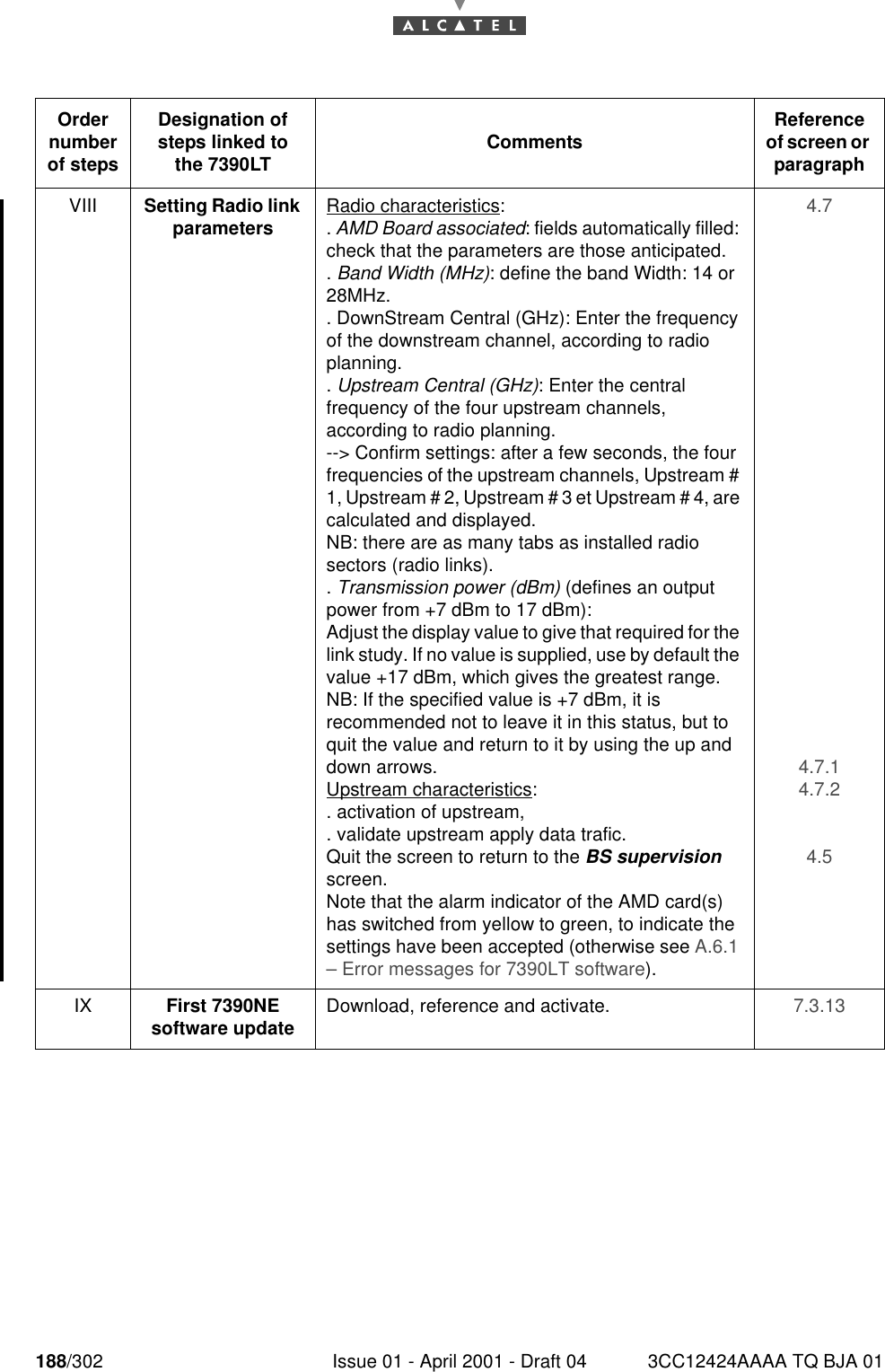
188/302 Issue 01 - April 2001 - Draft 04 3CC12424AAAA TQ BJA 01190Order number of stepsDesignation of steps linked to the 7390LT Comments Reference of screen or paragraphVIII Setting Radio link parameters Radio characteristics:. AMD Board associated: fields automatically filled: check that the parameters are those anticipated.. Band Width (MHz): define the band Width: 14 or 28MHz.. DownStream Central (GHz): Enter the frequency of the downstream channel, according to radio planning.. Upstream Central (GHz): Enter the central frequency of the four upstream channels, according to radio planning.--> Confirm settings: after a few seconds, the four frequencies of the upstream channels, Upstream # 1, Upstream # 2, Upstream # 3 et Upstream # 4, are calculated and displayed.NB: there are as many tabs as installed radio sectors (radio links).. Transmission power (dBm) (defines an output power from +7 dBm to 17 dBm):Adjust the display value to give that required for the link study. If no value is supplied, use by default the value +17 dBm, which gives the greatest range.NB: If the specified value is +7 dBm, it is recommended not to leave it in this status, but to quit the value and return to it by using the up and down arrows.Upstream characteristics:. activation of upstream,. validate upstream apply data trafic.Quit the screen to return to the BS supervision screen.Note that the alarm indicator of the AMD card(s) has switched from yellow to green, to indicate the settings have been accepted (otherwise see A.6.1 – Error messages for 7390LT software).4.7 4.7.1 4.7.2 4.5 IX First 7390NE software update Download, reference and activate. 7.3.13
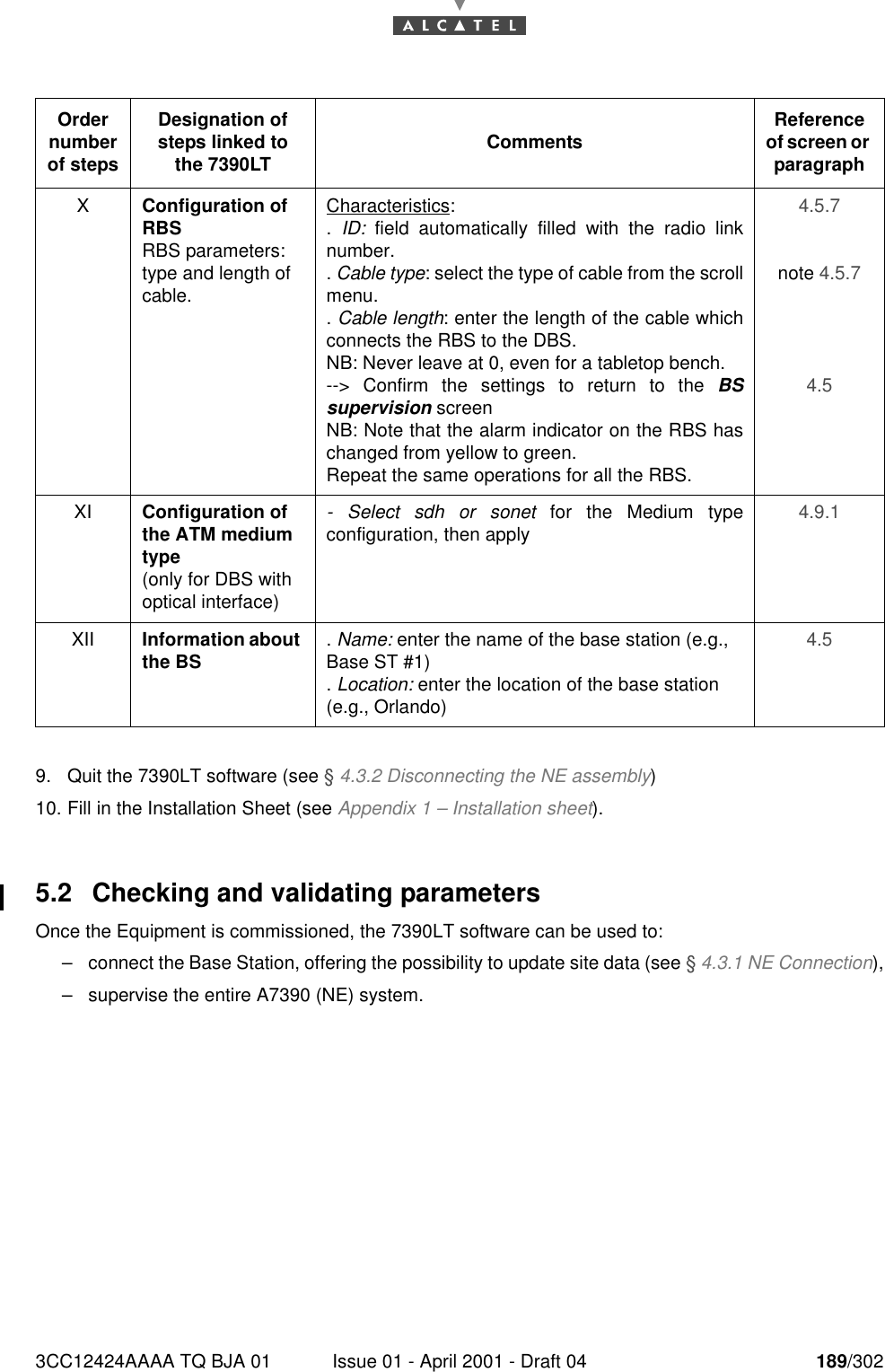
3CC12424AAAA TQ BJA 01 Issue 01 - April 2001 - Draft 04 189/3021909. Quit the 7390LT software (see § 4.3.2 Disconnecting the NE assembly)10. Fill in the Installation Sheet (see Appendix 1 – Installation sheet).5.2 Checking and validating parametersOnce the Equipment is commissioned, the 7390LT software can be used to:–connect the Base Station, offering the possibility to update site data (see § 4.3.1 NE Connection),–supervise the entire A7390 (NE) system.Order number of stepsDesignation of steps linked to the 7390LT Comments Reference of screen or paragraphXConfiguration of RBSRBS parameters: type and length of cable.Characteristics:.  ID: field automatically filled with the radio linknumber.. Cable type: select the type of cable from the scrollmenu.. Cable length: enter the length of the cable whichconnects the RBS to the DBS.NB: Never leave at 0, even for a tabletop bench.--> Confirm the settings to return to the BSsupervision screenNB: Note that the alarm indicator on the RBS haschanged from yellow to green.Repeat the same operations for all the RBS.4.5.7 note 4.5.7 4.5 XI Configuration of the ATM medium type(only for DBS with optical interface)- Select sdh or sonet for the Medium typeconfiguration, then apply 4.9.1 XII Information about the BS . Name: enter the name of the base station (e.g., Base ST #1). Location: enter the location of the base station (e.g., Orlando)4.5
190/302 Issue 01 - April 2001 - Draft 04 3CC12424AAAA TQ BJA 01190PAGE INTENTIONALLY LEFT BLANK

Navigation menu