Alcatel Canada 24T28A01D22C 7390 24 GHz Co-Pol RBS User Manual BS Manual pages 31 to 40

Alcatel Canada Inc 7390 24 GHz Co-Pol RBS BS Manual pages 31 to 40

BS Manual pages 31 to 40

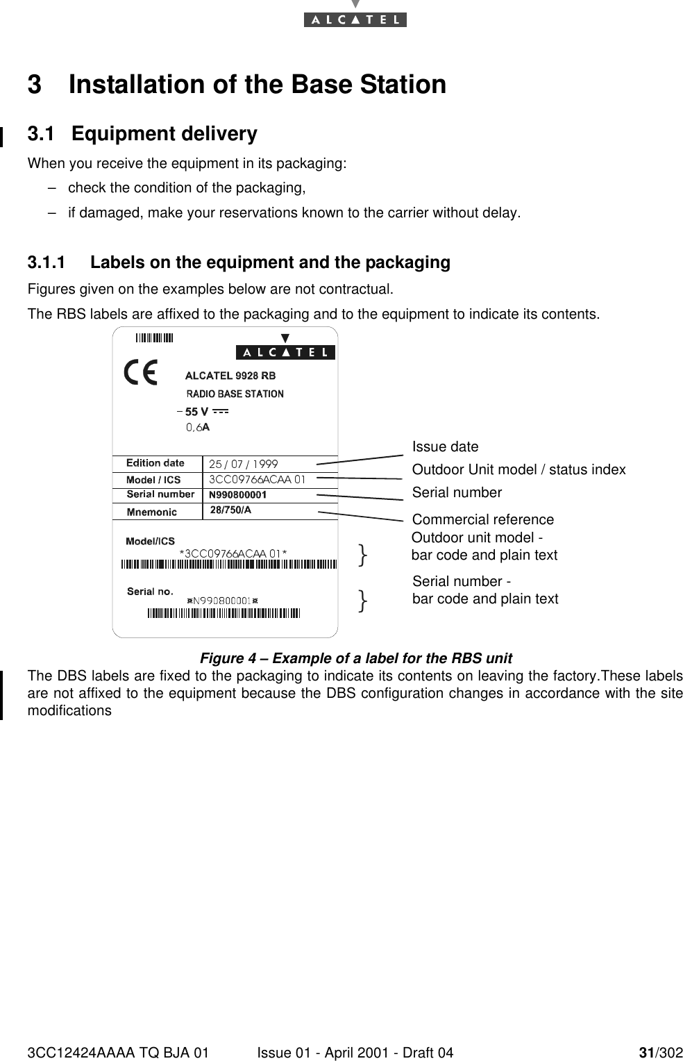
3CC12424AAAA TQ BJA 01 Issue 01 - April 2001 - Draft 04 31/302763 Installation of the Base Station3.1 Equipment deliveryWhen you receive the equipment in its packaging:–check the condition of the packaging,–if damaged, make your reservations known to the carrier without delay.3.1.1 Labels on the equipment and the packagingFigures given on the examples below are not contractual.The RBS labels are affixed to the packaging and to the equipment to indicate its contents.Figure 4 – Example of a label for the RBS unitThe DBS labels are fixed to the packaging to indicate its contents on leaving the factory.These labelsare not affixed to the equipment because the DBS configuration changes in accordance with the sitemodifications``Issue dateOutdoor Unit model / status indexSerial numberCommercial referenceOutdoor unit model -bar code and plain textSerial number -bar code and plain text
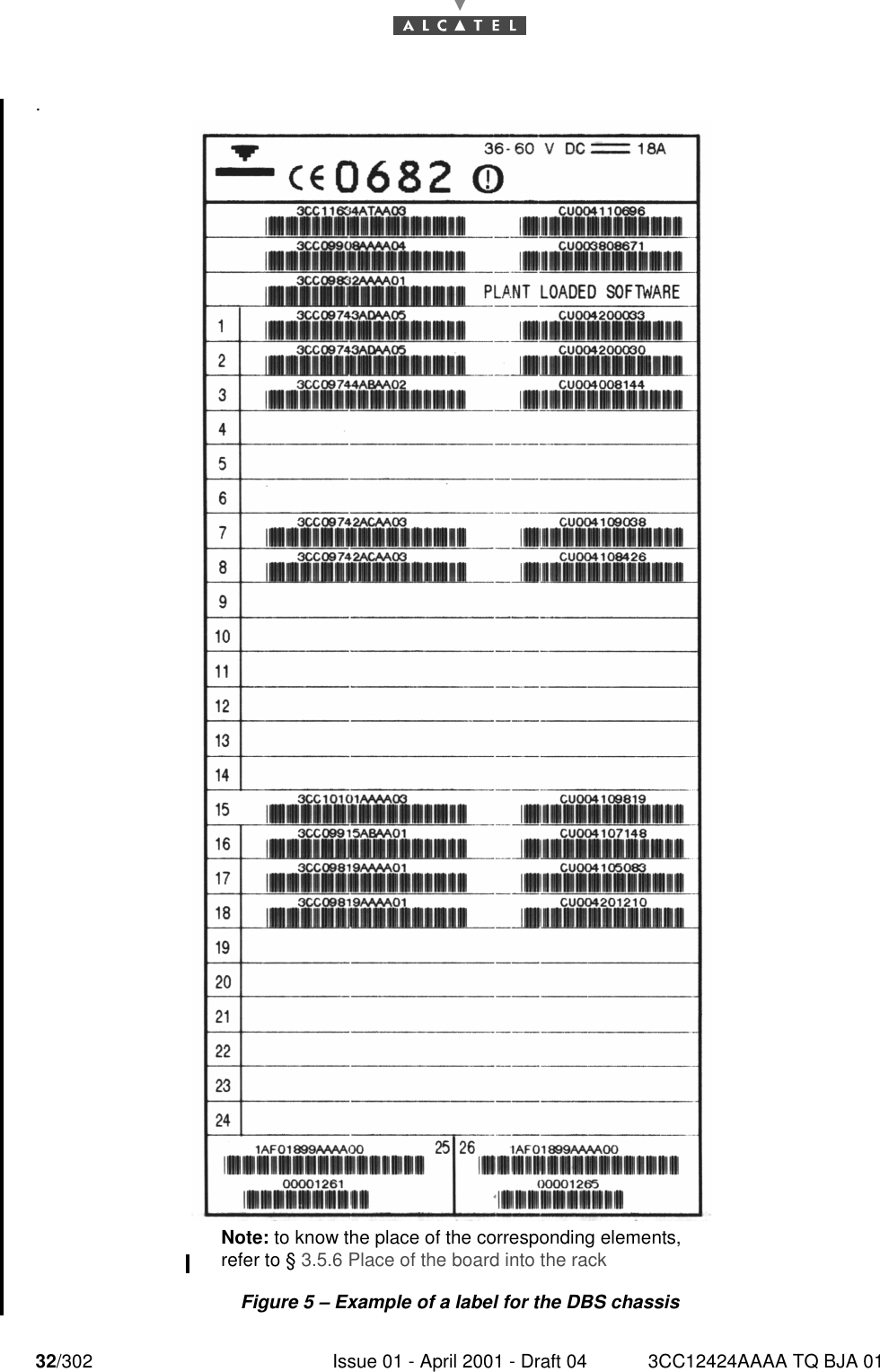
32/302 Issue 01 - April 2001 - Draft 04 3CC12424AAAA TQ BJA 0176.Figure 5 – Example of a label for the DBS chassisNote: to know the place of the corresponding elements, refer to § 3.5.6 Place of the board into the rack
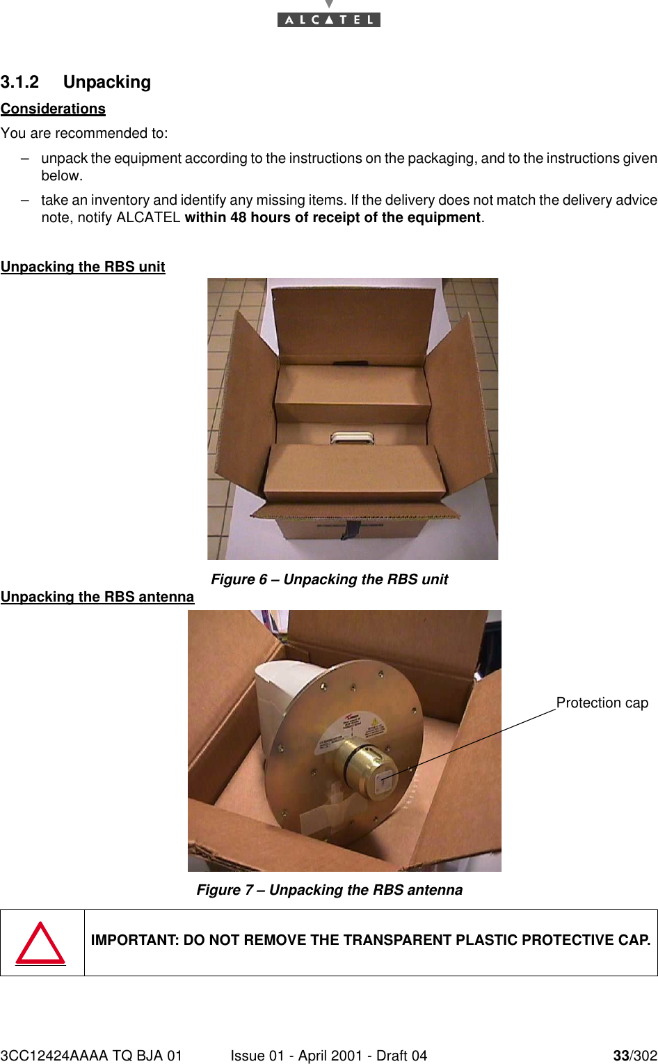
3CC12424AAAA TQ BJA 01 Issue 01 - April 2001 - Draft 04 33/302763.1.2 UnpackingConsiderationsYou are recommended to:–unpack the equipment according to the instructions on the packaging, and to the instructions givenbelow.–take an inventory and identify any missing items. If the delivery does not match the delivery advicenote, notify ALCATEL within 48 hours of receipt of the equipment.Unpacking the RBS unitFigure 6 – Unpacking the RBS unitUnpacking the RBS antennaFigure 7 – Unpacking the RBS antennaIMPORTANT: DO NOT REMOVE THE TRANSPARENT PLASTIC PROTECTIVE CAP.Protection cap
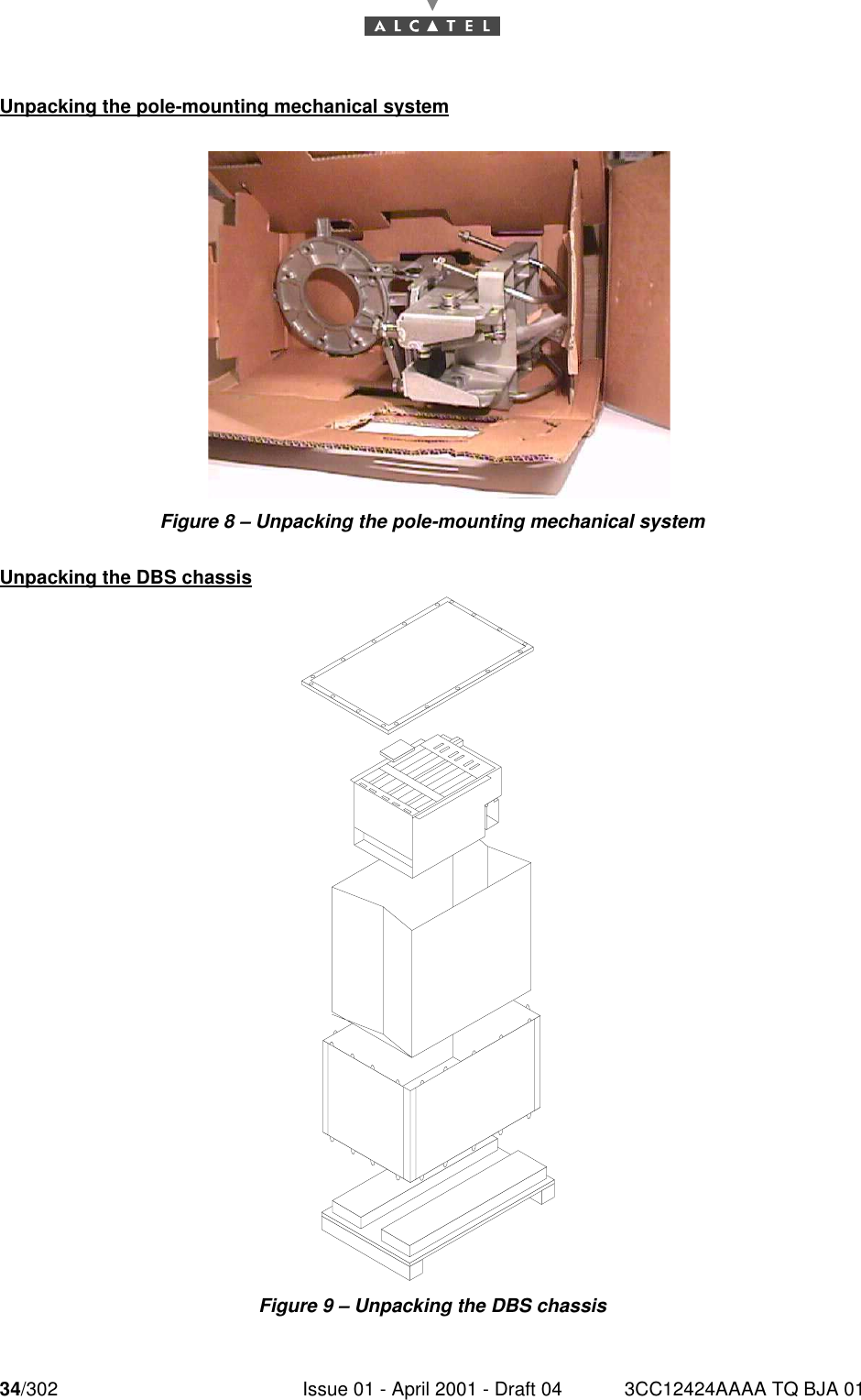
34/302 Issue 01 - April 2001 - Draft 04 3CC12424AAAA TQ BJA 0176Unpacking the pole-mounting mechanical systemFigure 8 – Unpacking the pole-mounting mechanical systemUnpacking the DBS chassisFigure 9 – Unpacking the DBS chassis
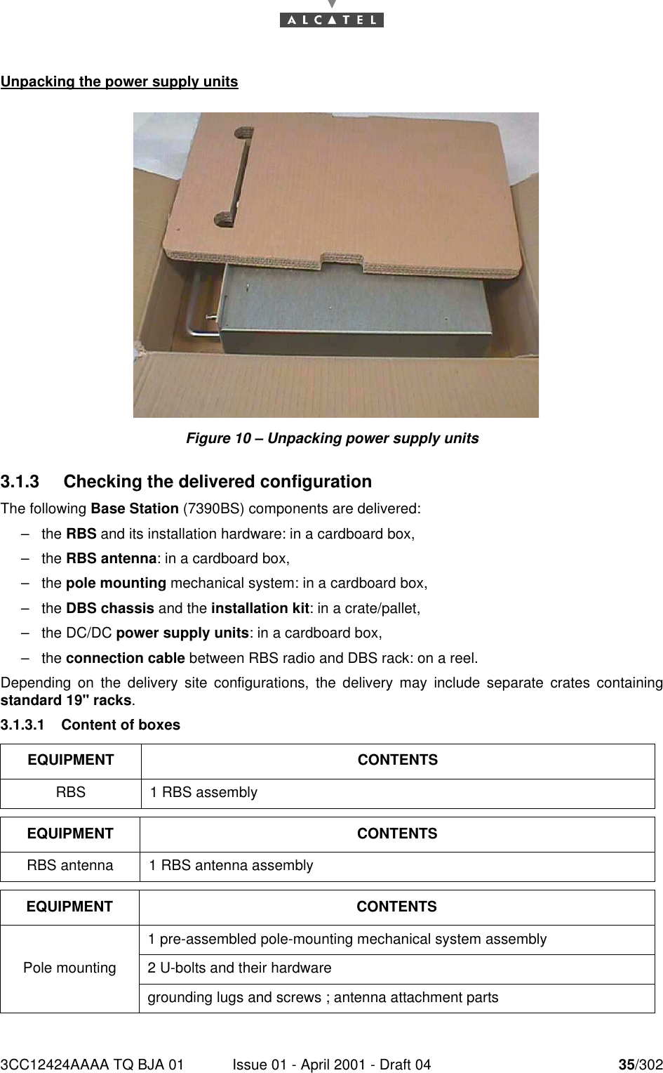
3CC12424AAAA TQ BJA 01 Issue 01 - April 2001 - Draft 04 35/30276Unpacking the power supply unitsFigure 10 – Unpacking power supply units3.1.3 Checking the delivered configurationThe following Base Station (7390BS) components are delivered:–the RBS and its installation hardware: in a cardboard box,–the RBS antenna: in a cardboard box,–the pole mounting mechanical system: in a cardboard box,–the DBS chassis and the installation kit: in a crate/pallet,–the DC/DC power supply units: in a cardboard box,–the connection cable between RBS radio and DBS rack: on a reel.Depending on the delivery site configurations, the delivery may include separate crates containingstandard 19" racks.3.1.3.1 Content of boxesEQUIPMENT CONTENTSRBS 1 RBS assemblyEQUIPMENT CONTENTSRBS antenna 1 RBS antenna assemblyEQUIPMENT CONTENTSPole mounting1 pre-assembled pole-mounting mechanical system assembly2 U-bolts and their hardwaregrounding lugs and screws ; antenna attachment parts
36/302 Issue 01 - April 2001 - Draft 04 3CC12424AAAA TQ BJA 01763.1.3.2 StorageIf the installation is not to be carried out immediately, the type of packaging will determine the equipmentstorage conditions:–the cardboard boxes should be warehoused indoors, in a well-ventilated and dry space,–the wooden or laminated crates may be stored outdoors, provided that they are protected from therain and direct sunlight.EQUIPMENT CONTENTSDBS chassis1 chassis containing the electronic boards according to the client configurationcables (for IBS board interface, N panel), in accordance with the site configurationfiber optic jumpers, in accordance with the site configuration2 fiber optic cable winding cassettes1 set of screws to install the rack into the chassisEQUIPMENT CONTENTSDC/DC power supply  2 DC/DC power supply unitsEQUIPMENT CONTENTSOptionaStandard 19"rack 1 rack with removable top cover and adjustable feet
3CC12424AAAA TQ BJA 01 Issue 01 - April 2001 - Draft 04 37/302763.2 Installing the equipment3.2.1 Information required for installationAppendix 1 – Installation sheet contains a sheet for you to complete, that compiles all the generalinformation needed for the installation procedure.3.2.2 PrecautionsInstallation is designed to meet all requirements concerning electromagnetic compatibility and safety.The performance of the equipment depends on installation practices (cable installation, groundconnections, etc.) which should be based on best trade practices and which may be degraded if thesespratices are not respected.3.2.3 Tools requiredThe installation team must possess a standard installation toolkit (containing, in particular: drill, drill bits,soldering iron, cable tie pliers, terminal pliers).The list of tools required for the mechanical installation of the equipment is given below:For installation and alignment procedure for an RBS 7390 with a sector antenna, refer to the UserManual 3CC12087Axxx.Tool UseNo. 6 Allen wrench (for 8 mm screw) Antenna alignment16/17 mm box wrench and flat wrench Used for pole mounting and for fine adjustment of the antenna and various tightening operations16/17 mm Torque wrench Used for pole mounting and various tightening operations20 mm flat wrench For attaching the "N" coaxial connectorsCompax "Mars Actel OSA3" inser-tion and extraction tool Wiring the COMPAX (mars actel cad) terminal stripsEssential compass and inclinome-ter (not supplied) Pointing the antenna5 mm Allen key (for M6 screw) For mounting the antenna10 mm flat wrench For fixing the ground terminal8 mm Allen key (for M10 screw) For tightening the different parts of the pole mountingComplete antenna pointing tool kit 3CC11782Axxx Pointing the antenna
38/302 Issue 01 - April 2001 - Draft 04 3CC12424AAAA TQ BJA 0176Depending on the installations, additional equipment, provided by Alcatel as optional, may prove useful:To get the commercial codes of these items, please consult Appendix 5 – Correspondence betweencommercial codes and industrial codes relating to the BS which gives the connection between industrialand commercial codes.3.3 Installation of outdoor equipmentConsiderations–Outdoor equipment installation involves:•installation of the mechanical system (also called "pole mounting" system) which supports theRBS and facilitates antenna alignment,•installation of the RBS assembly and its antenna,•installation of the connection cable connecting the RBS to the DBS rack.–Outdoor equipment installation should guarantee a precise and fixed antenna pointing.–The RBS location and its antenna orientation should arise from a planning analysis in order to op-timize the sector coverage. These elements must be imperatively known with precision by the ins-tallation staff.–Antenna orientation is carried out according to geometric criterion (using compass and inclinome-ter).–All the outdoor equipment assemblies are designed for installation without any particular protec-tion. However, the following recommendations must be respected:•make sure that the reception metallic structure has a perfect stability,•do not install the equipment below bird nesting areas,•do not attach the equipment to chimneys which give off fat deposits, dust and other aerosolswhich are liable to be deposited on the equipment,•do not install the equipment in proximity to sources of heat,•do not place the equipment in proximity to corrosive gas outputs,•do not place the equipment below roof run-offs not equipped with guttering (high risk of micro-wave short-circuit),•do not attach the equipment to a structure prone to vibrations,•do not cross the antenna field.–Two types of installation are possible:1. installation on a tube or pole, using threaded U-bolts and nuts.Note: the tube selected should be sufficiently rigid to resist vibrations that may give rise to antennamisalignment.2. wall mounting: direct or with mounting plate: see Figure 63 – Direct wall mounting and Figure 64 –Wall mounting option with mounting plate 9900UXI101 in Appendix A.7.Tool Use Industrial CodeCrimping tool Sub-D connectors crimping 9900YTB001
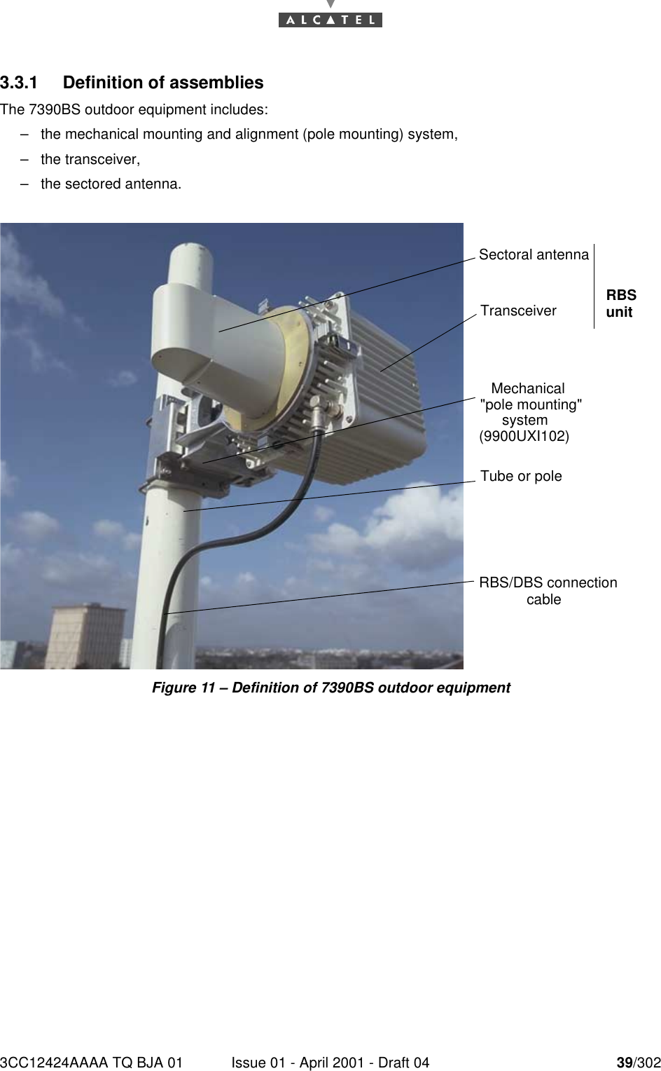
3CC12424AAAA TQ BJA 01 Issue 01 - April 2001 - Draft 04 39/302763.3.1 Definition of assembliesThe 7390BS outdoor equipment includes:–the mechanical mounting and alignment (pole mounting) system,–the transceiver,–the sectored antenna.Figure 11 – Definition of 7390BS outdoor equipmentSectoral antennaTube or poleRBS/DBS connection cableMechanical "pole mounting" system (9900UXI102)Transceiver RBS unit
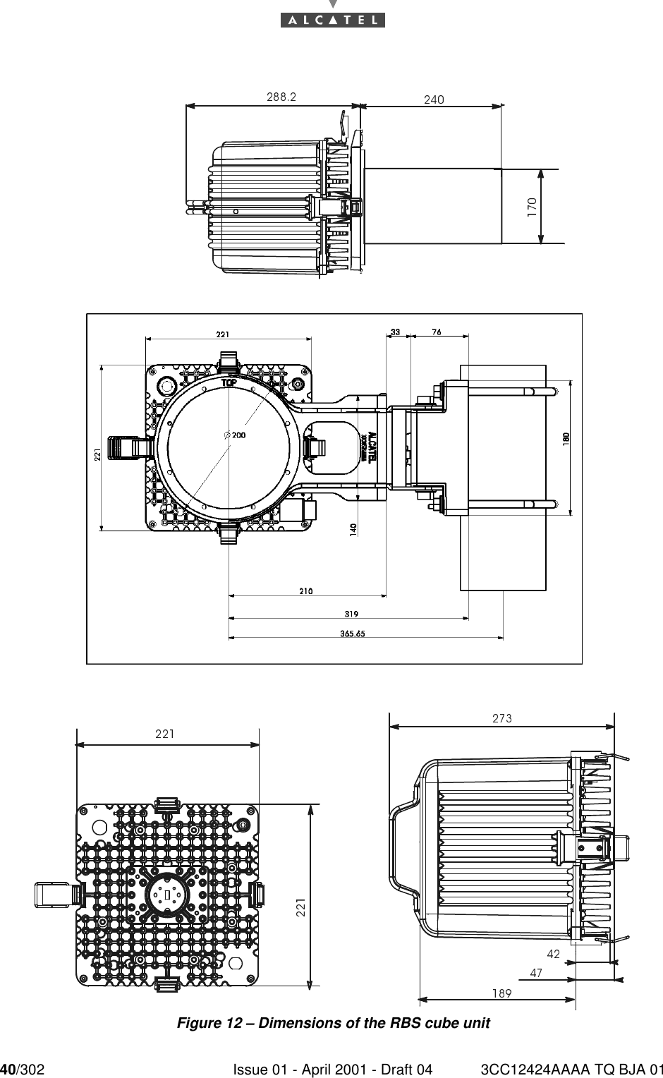
40/302 Issue 01 - April 2001 - Draft 04 3CC12424AAAA TQ BJA 0176Figure 12 – Dimensions of the RBS cube unit

Navigation menu