Alcon Research PUREPT1 PurePoint User Manual NGL Book 1 indb
Alcon Research Ltd. PurePoint NGL Book 1 indb
Contents
- 1. User Manual part 1 of 5
- 2. User Manual part 2 of 5
- 3. User Manual part 3 of 5
- 4. User Manual part 4 of 5
- 5. User Manual part 5 of 5
User Manual part 5 of 5

8065751131 5.1
SECTION FIVE
TROUBLESHOOTING
SYSTEM MESSAGES
System messages advise the user of a system condition that requires an action and/or
a response in order to proceed with the current procedure.
Advisory Messages
Advisory messages (see Table 5-1) are informational messages that help guide the
user or bring attention to the laser’s condition.
• Advisory messages appear on the same blue-gray background that many labels and
prompts appear on.
• Advisory messages can appear when the device is in Standby or Ready mode. They do
not appear when the device is in Firing mode.
• Advisory messages will cause the system to switch from Ready to Standby mode.
Warning Messages
Warning messages (see Table 5-2) are precautionary messages displayed on a yellow
background to inform the user of a possible safety or procedural problem that may
occur in any mode. The following events take place:
• The laser is placed into Standby mode.
• The user is presented with one of two types of display, an Acknowledgement screen or
an Operating screen, each of which asks for an action before the user continues with the
procedure:
The Acknowledgement Screen presents the user with information that describes the
problem. The user must select a response, using the Menu knob, stating that they have
seen and acknowledged the message. This acknowledgement is recorded in the laser’s
system log. The display returns to the regular operating display in Standby mode.
Attempting to go to Ready Mode without taking requested action results in the system
continuing to display the Acknowledgement Screen.
The Operating display allows the user to perform operational tasks such as adjusting
the laser parameters while a warning prompt appears at the top of the screen asking
the user to perform an action. After the requested action is performed, the warning
prompt is removed and the display returns to the regular operating display in Standby
mode. If the user tries to go to Ready mode without performing the requested action,
the prompt starts blinking in order to get the attention of the user. The laser will
remain in Standby mode until the action is performed.
5.2
8065751131
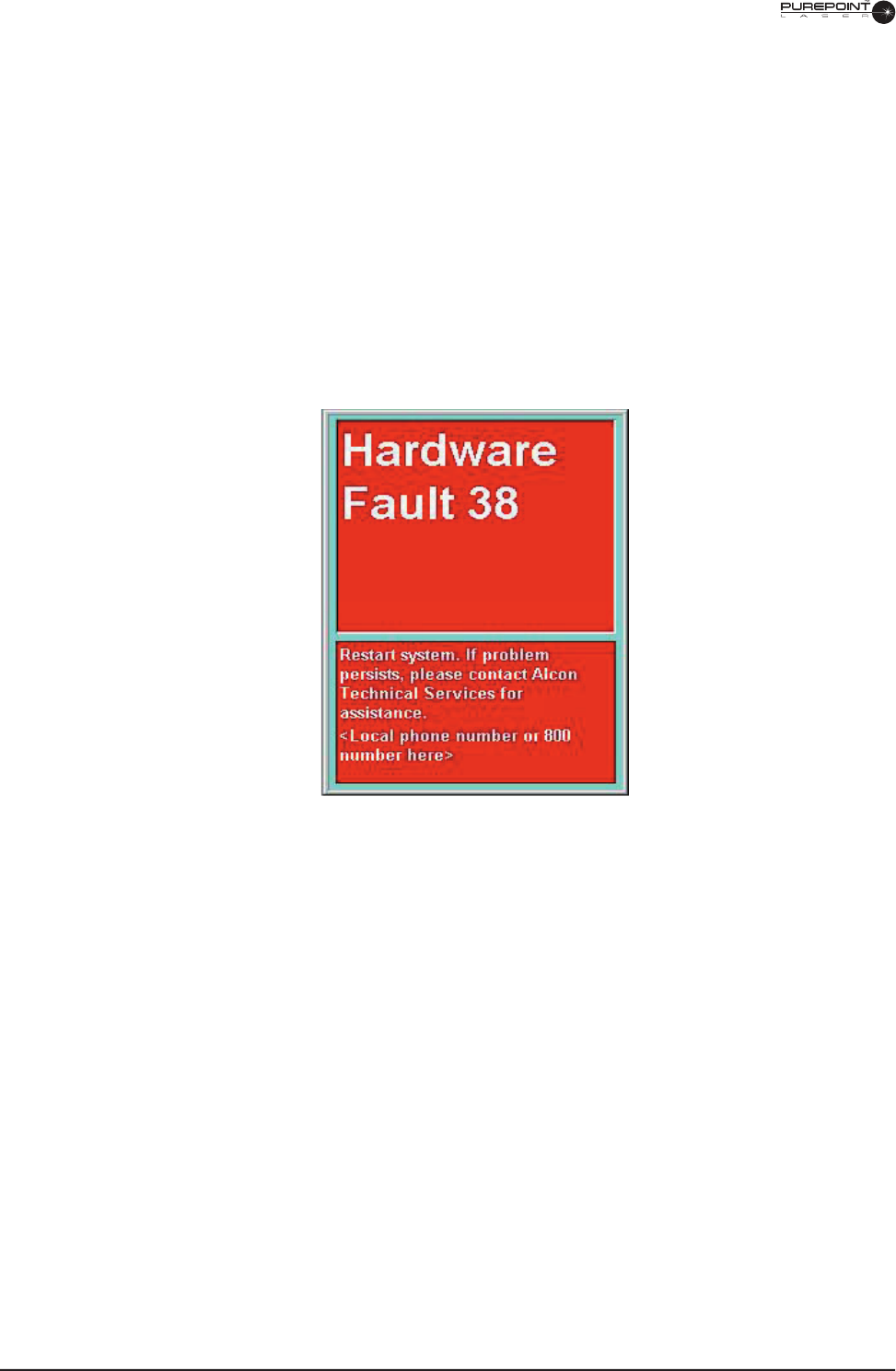
Error Messages
Errors are major faults in the system that cannot be resolved by either software,
hardware, or user action. The following events take place:
• The laser is placed in a safe state (laser engine is turned off and shutter is closed).
• The user is told by an error message and voice confi rmation that a fault has taken place.
• The front panel controls are not functional other than the emergency shut-off switch and
the On/Off key. The footswitch controls are also not functional.
An error message is usually an indication that the system requires service in order
to correct the problem. If restarting the system does not resolve the problem, contact
your local Alcon representative to schedule a service call.
Figure 5-1 Error Message

8065751131 5.3
Table 5-1. Advisory Messages
Message Displayed Condition Action
“Unable to recognize probe type in
Port XX.
Please select probe type from
options below.”
An unidentifi ed fi ber is connected
to a laser port. The laser fi ber may
not include a RFID tag or the tag’s
data may be corrupted.
User must select a probe type (slit
lamp, LIO, or Endo) to clear the
message.
“Please Insert Probe.
Select the Main Menu button to
view or alter settings.”
Unit completes boot-up and no
probe has been inserted.
User must connect a fi ber to a
laser port or select the Main Menu
button to clear the message.
“Maximum Power Available: 1.5W”
(any number under 2W will be
displayed; in this case it is 1.5W)
Power available from the laser
drops below the maximum level (2
Watts).
User must acknowledge the
screen prompt to clear the
message.
“Requested Power Not Available” The operator depresses the
footswitch, but the laser is
unable to deliver the power value
requested.
User must acknowledge the
screen prompt to clear the
message. User should then
reduce laser power.
“Service Engine Soon” The laser has a signifi cant
drop in its maximum power or
system detects other potential
maintenance need.
User must acknowledge this
prompt to clear the message. If
the service has not been done,
the message repeats with every
boot-up.
"Footswitch side switches control
power to laser."
Message is displayed at boot
up to inform the user that the
footswitch side switches are set to
adjust power only.
User must acknowledge this
prompt to clear the message.
"Footswitch side switches may be
used to change from Standby to
Ready and back."
Message is displayed at boot up to
inform the user that the footswitch
side switches have been set to
switch between Standby and
Ready.
User must acknowledge this
prompt to clear the message.
"Footswitch side switches have
been de-activated."
Message is displayed at boot
up to inform the user that the
footswitch side switches have
been de-activated.
User must acknowledge this
prompt to clear the message.

5.4
8065751131
Table 5-2. Warning Messages
Message Displayed Condition Action
“Footswitch Confi guration
0 Power
0 Standby/Ready”
The fi rst time after system initialization that
a multi-function footswitch is connected
and not in Disabled mode.
User must acknowledge the
message to clear the screen
and continue.
“Verify appropriate Dr. Filters
are installed in all viewing
devices.”
Acknowledgement Screen
The fi rst time after system initialization
that either a slit lamp or endo laser fi ber is
selected while at least one tethered doctor
fi lter is connected.
User must acknowledge the
message to clear the screen
and continue.
Verify appropriate Dr. Filters
are installed in all viewing
devices.”
Acknowledgement Screen
Either a slit lamp or endo laser fi ber is
selected and no tethered doctor fi lter is
connected.
User must acknowledge the
message to clear the screen
and continue.
“Please Engage Dr. Filter”
Operating display
A tethered doctor fi lter is disengaged. User must engage the doctor
fi lter to clear the message.
“Please Connect Dr. Filter”
Operating display
A tethered doctor fi lter is disconnected
while the system is in Ready or Firing
mode.
User must connect a tethered
doctor fi lter to clear the
message.
“Please Release Footswitch”
Operating display
Operator initiates switching from Standby
to Ready while the footswitch is depressed.
User must cease pressing
footswitch to clear the
message.
“Please Connect Footswitch”
Operating display
The footswitch is disconnected in any
mode.
Footswitch must be re-
connected to clear the
message.
“Please Close Remote
Interlock”
Operating display
The remote interlock circuit detects a door
is opened or the remote interlock plug is
disconnected from the back panel.
Door must be closed or plug
re-connected to clear the
message.
“Port 1 cannot be used.
Please use Port 2.”
Acknowledgement Screen
A fault exists on one laser port, but the
other port is still usable.
User must acknowledge the
message and only use the
functioning port.
LAST PAGE OF THIS SECTION
8065751131LAST PAGE OF THIS SECTION 8065751131

8065751131 6.1
SECTION SIX
ACCESSORIES AND PARTS
This section of the manual contains the various
accessories that are available for use with the
PurePoint
™
Laser (see Table 6-1). If additional information is required for setup and use of the
™ Laser (see Table 6-1). If additional information is required for setup and use of the
™
accessory, the Notes column of Table 6-1 provides references to that information.
TABLE 6-1.
PUREPOINT™
LASER ACCESSORIES
Description
Catalog Number
Notes
Endo Ocular Laser Probe, Straight, 20 Gauge
8065678610
Endo Ocular Laser Probe, Curved, 20 Gauge
8065010203
Endo Ocular Laser Probe, Straight, 20 Gauge
8065010219
Endo Ocular Laser Probe, Straight, 23 Gauge
8065750803
Endo Ocular Laser Probe, Straight, 25 Gauge
8065750133
Endo Ocular Laser Probe, Curved, 20 Gauge, W/RFID
8065750989
Endo Ocular Laser Probe, Straight, 20 Gauge, W/RFID
8065750990
Endo Ocular Laser Probe, Straight, 25 Gauge, W/RFID
8065750978
Endo Ocular Laser Probe, Straight, 23 Gauge, W/RFID
8065750991
Chang Aspirating Laser Probe, Curved, 20 Gauge
8065010703
Chang Aspirating Laser Probe, Straight, 20 Gauge
8065010719
Chang Aspirating Laser Probe, Soft Tip, 20 Gauge
8065010739
Chang Aspirating Laser Probe, Curved, 20 Gauge, W/RFID
8065750979
Chang Aspirating Laser Probe, Straight, 20 Gauge, W/RFID
8065750980
Chang Aspirating Laser Probe, Soft Tip, 20 Gauge, W/RFID
8065750981
Illuminated Endo Ocular Laser Probe, Curved, 20 Gauge
8065010403
Illuminated Endo Ocular Laser Probe, Curved, 20 Gauge
8065010404
Illuminated Endo Ocular Laser Probe, Straight, 20 Gauge
8065010419
Illuminated Endo Ocular Laser Probe, Straight, 20 Gauge
8065010420
Illuminated Endo Ocular Laser Probe, Curved, 20 Gauge, W/RFID
8065750982
Illuminated Endo Ocular Laser Probe, Straight, 20 Gauge, W/RFID
8065750983
Slit Lamp Front Actuating Doctor Protection Filter
8065750260
Microscope Front Actuating Doctor Protection Filter
8065750448
PurePoint™ Passive Dr. Filter
8065751051
Slit Lamp: Alcon® SL 1000 (CSO Table)
Adaptation
Fiber Strain Relief
8065740982
8065741019
8065750256
See pages 6-2 &
6-5
Slit Lamp: Zeiss 30SL (Topcon Table)
Adaptation
Fiber Strain Relief
8065-5010-01
8065750256
See pages 6-2 &
6-5
Slit Lamp: Haag-Streit 900 BM (Haag-Streit Table)
Adaptation
Fiber Strain Relief
8065-5011-01
8065750256
See page 6-3
Laser Indirect Ophthalmoscope
8065751050
See page 6-10
6.2
8065751131
SLIT LAMPS WITH DOCTOR PROTECTION FILTERS AND ADAPTATIONS
A
slit lamp assembly is typically used to deliver the
PurePoint
™
laser treatment beam to the
™ laser treatment beam to the
™
patient's eye. An
adaptation, mounted on the slit lamp, is required to interface the slit lamp to
the
PurePoint™
laser.
PurePoint™ laser.PurePoint™
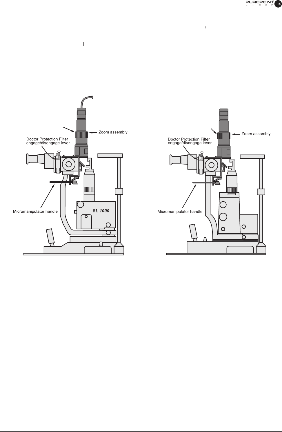
The adaptation consists of a zoom assembly with micromanipulator and a
Doctor Protection
Filter. The Doctor Protection Filter provides eye protection for the physician. The parfocal
zoom assembly is used to set the spot size of the aiming and treatment beams, and a
micromanipulator is provided for fi ne adjustment of the beam position.
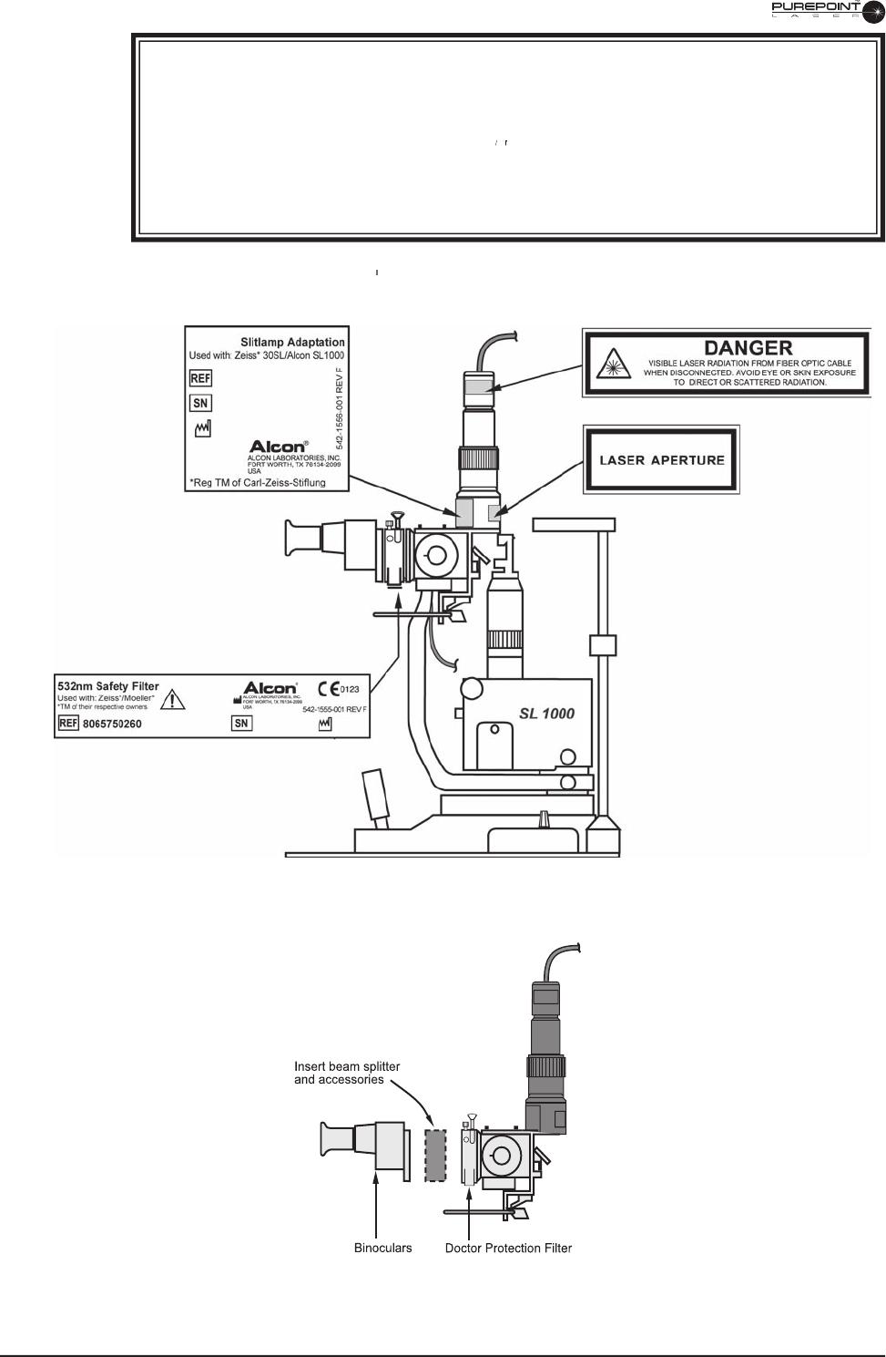
Figure 6-1 Alcon SL1000 Slit Lamp
Spot size
adjusting knob
Spot size
adjusting knob
Figure 6-2
Zeiss 30SL
8065751131 6.3
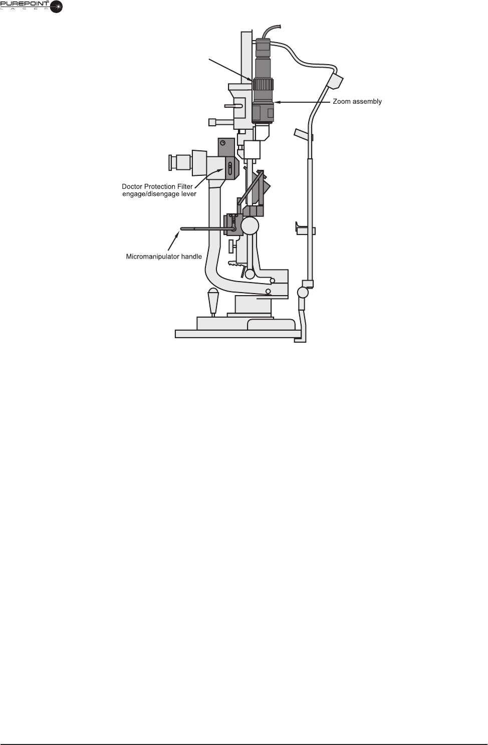
Figure 6-3 Haag-Streit 900
BM
Spot size
adjusting knob
6.4
8065751131
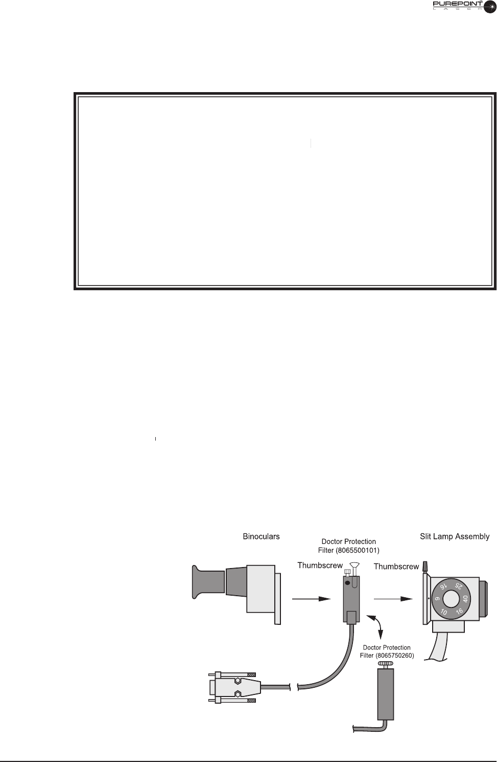
Figure 6-4
Doctor Protection Filter Mounted
Between Binoculars and Slit Lamp
Assembly
Connect to Dr. filter port
on laser console rear panel
** Newer Doctor Protection Filters will have less tint than older ones.
POSITIONING THE DOCTOR PROTECTION FILTER
The
Doctor Protection Filter is used to protect the surgeon from harmful laser radiation that
could damage his eyes. The Doctor Protection Filter is inserted between the binoculars and
the slit lamp or microscope.
WARNINGS!
It is the operator's responsibility to properly install the Doctor Protection Filter
and verify operation.
Using the instrument with a Doctor Protection Filter that
is improperly installed could result in operator
injury. Alcon shall not be held
is improperly installed could result in operator
injury. Alcon shall not be held
is improperly installed could result in operator
liable for problems caused by improper installation of the Doctor Protection
Filter. Defeat of the
D
octor Protection Filter interlock switches and/or incorrect
installation of the
D
octor Protection Filter to the microscope could result in
ocular hazards to the surgeon.
Operator will have a colored** view through the Doctor Protection Filter due to
blocking of the 532nm wavelength (green).
Operator must be careful to avoid potential secondary refl ections; therefore, the
room used to treat the patient should be approved by a qualifi ed laser safety
offi cer.
1. Loosen thumbscrew on slit lamp assembly (or microscope) and remove binoculars (see
Figure below).
2. Place Doctor Protection Filter into position on the slit lamp assembly and secure with
thumbscrew.
3. Place binoculars into position on the Doctor Protection Filter and secure with
thumbscrew.
4. Connect electrical cable connector to the Doctor Protection Filter port on the
PurePoint
™
rear panel.
™ rear panel.
™
5. Perform the System Power Up instructions for the
PurePoint
™
Laser
in Section Three
of this manual. Move the Doctor Protection Filter lever to disengage the fi lter and
verify proper function; the message "Engage Dr. Filter" should appear.
If the message
does not appear, do not use the instrument; call Alcon Technical Services.

8065751131 6.5
ALCON SL 1000 AND
ZEISS
30SL ADAPTATION
ZEISS 30SL ADAPTATIONZEISS
Introduction
The Doctor Protection Filter, fi ber optic cable, mechanical micromanipulator with zoom,
and beam splitter/accessories in combination with the
Alcon
SL 1000 Slit Lamp (or
Zeiss
30SL) are designed exclusively for use with the
PurePoint
™
laser system. This instrument
™ laser system. This instrument
™
combination represents a complete ophthalmic unit. Please refer to the Alcon SL 1000 (or
Zeiss
30SL) Operator's Manual for information not included in this manual.
The micromanipulator with zoom provides interface between the
PurePoint
™
laser system
™ laser system
™
and the patient. The laser spot is focused and traversed in the X and Y direction by means of
the slit lamp
joystick. The micromanipulator control lever provides additional positioning of
the laser spot. The micromanipulator with integral zoom is used to adjust the laser spot size.
The mandatory Doctor Protection Filter provides protection from the 532nm laser radiation
for the attending physician. The safety circuit of the
PurePoint
™
laser is designed to insure
™ laser is designed to insure
™
the safety fi lters are engaged (moved into place) prior to the treatment laser being operational.
WARNINGS!
Ensure that the terminal selection on the
PurePoint
™
front panel is SLIT LAMP. Verify
™
front panel is SLIT LAMP. Verify
™
that the selection is correctly confi rmed. It is the responsibility of the operator to
connect and confi rm the selected terminal.
Operator will have a colored** view through the Doctor Protection Filter due to
blocking of the 532nm (green) wavelength.
To avoid potential secondary refl ections, the room used to treat the patient must
be approved by a qualifi ed
laser safety offi cer.
All personnel in the treatment room must wear protective eyewear (OD 4 or above
at
532nm) when the system is in Standby or Ready modes.
Installation of the complete instrument system or retrofi tting an existing SL 1000
slit lamp with a micromanipulator with zoom, a beam splitter/accessories, a fi ber
optic cable, and a Doctor Protection Filter should only be done by Alcon Service
Personnel or persons authorized by Alcon.
A qualifi ed technician must perform a visual inspection of the following components
every twelve months: warning labels, power cords, fuses. In case of a defi ciency,
do
not use the system; contact Alcon Technical Services.
Before each use, ensure the Doctor Protection Filter assembly, the micromanipulator
with zoom,
and the fi ber optic cable are fi rmly attached to the slit lamp. The user
must also check
the Doctor Protection Filter elements for scratches, breaks, or
alterations. If scratched, damaged, or loosely attached, discontinue use of device
immediately and contact Alcon Technical Services.
When using beam splitter accessories, the binoculars must fi rst be attached to the
beam splitter (the beam splitter accessories are attached to the beam splitter on the
protected side of the Doctor Protection Filter assembly); the beam splitter is then
attached to the permanently installed Doctor Protection Filter. Improper installation
could cause injury to the operator and/or the patient.
** Newer Doctor Protection Filters will have less tint than older ones.
6.6
8065751131
Figure 6-6
To avoid injury, the
beam splitter/accessories must be placed
between the binoculars and Doctor Protection Filter (Alcon SL 1000 shown)
WARNINGS!
Verify that the label marking the laser exit aperture is in place. Refer to the fi gure
below for the location of labels on the Alcon SL 1000.
Never treat a patient when the
PurePoint
™
PurePoint™
PurePoint
Laser is connected to a service computer.
™
Laser is connected to a service computer.
™
Defeat of the Doctor Protection Filter switches and/or incorrect installation of the
Doctor Protection Filter assembly
could result in ocular hazards to the surgeon.
Please refer to the
PurePoint
™
Operating Instructions in section three for further
™ Operating Instructions in section three for further
™
warnings.
Figure 6-5
Label Location Diagram on Adaptation - Alcon SL 1000 shown
8065751131 6.7
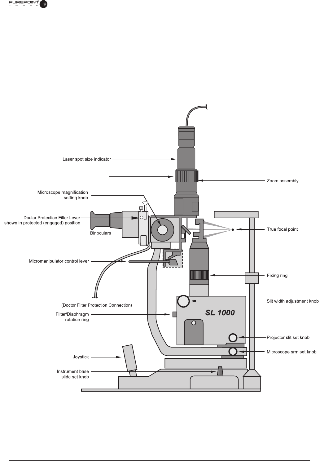
Adaptation Controls
Laser Spot Size Indicator
- Indicates diameter of laser spot in the microscope focal plane.
Laser Spot Size Adjustment Lever
- Used to adjust the laser spot size.
Micromanipulator Control Lever -
Used to position the laser spot around the microscope
center fi eld of view.
Figure 6-7
Controls on Alcon
SL 1000 Slit Lamp with Doctor Protection Filter and Adaptation Installed
Laser spot size adjustment knob
Fiberoptic from EyeLite®
To laser console

6.8
8065751131
Operation
Operation of the Doctor Protection Filter
• Before operating the slit lamp, the
Doctor Protection Filter cable must be plugged in and
fi rmly attached to the rear panel of the
PurePoint
™
laser system.
™ laser system.
™
• The Doctor Protection Filter is operated by moving the lever from the unprotected
position to the fi lter protected (engaged) position. The 532nm laser treatment beam is not
operational until the fi lter lever is in the engaged position.
• When using beam splitter accessories, the binoculars must fi rst be attached to the
beam
splitter (the beam splitter accessories are attached to the beam splitter on the protected
side of the Doctor Protection Filter assembly); the beam splitter is then attached to the
permanently installed Doctor Protection Filter (see Figure 6-9).
Positioning and
Focusing the Laser Beam
1. Move the joystick left and right to horizontally position the laser spot and illumination
slits.
2. Rotate the joystick to vertically position the laser spot.
3. Move the joystick forward and backward to focus the laser spot.
Adjusting the
Laser Position and Spot Size
1.
Following customary methods, position patient and place the contact lens on patient's eye.
2. Using the joystick control on instrument base, bring the selected area of treatment into
position/focus. If desired, lock instrument base in position with instrument base slide
set knob.
3. To position the laser spot, choose one or a combination of the following methods:
3.1 Using the joystick control, position the laser spot on the selected treatment area.
3.2 Using the micromanipulator, position the laser spot around the microscope center
fi eld of view.
3.3 Tilt the contact lens.
4. Use the laser spot size adjustment lever to set the laser spot size.
Laser Treatment of the Eye
1. The Doctor Protection Filter must be connected and in working order. To protect the
user's eyes, the fi lter must be in the engaged position prior to fi ring the treatment laser.
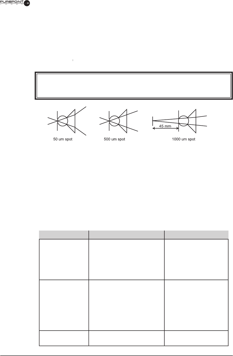
2. For laser spot sizes ranging from 50 µm to 500 µm, the focus is parfocal; i.e., the focus
of the laser spot lies in the focal plane of the microscope (see Figure 6-11). For laser
spots greater than 500 µm, the laser spot sizes are set by defocusing the laser; i.e., the
laser focus will not lie in the focal plane of the microscope).
8065751131 6.9
3. If the diopter adjustment(s) of the microscope eyepieces are not accurate, the object and
the laser focal point will not be in the same plane (for values between 50 µm and 500
µm). Consequently, the laser spot size on the fundus will be larger than the values set
on the zoom.
4. To position the laser spot, use the procedures outlined in the previous section.
5. Activate the treatment laser only if the target area has been clearly localized and
irradiation by a treatment laser is warranted. Follow the operating instructions for the
PurePoint
™
laser to operate the laser control console and activate the laser treatment
™ laser to operate the laser control console and activate the laser treatment
™
beam.
WARNING!
If the red aiming beam is not operating, do not use the system; contact Alcon
Technical Services.
Figure 6-8 Laser Spot Focus
Table 6-2
Adaptation Troubleshooting
SYMPTOM
No Aiming Beam
(red)
No Treatment Beam
(532nm - green)
Laser spot cannot
be positioned
PROBABLE CAUSE
Laser not switched on.
Aiming beam set too low.
Fiber optic cable not connected.
Aiming beam inoperative.
Laser not switched on.
Doctor Protection Filter not
properly connected to Laser.
Filters not engaged.
Fiber optic cable not connected.
Zero position lock knob in locked
position.
CORRECTIVE ACTION
Turn on
Laser.
Turn up intensity.
Connect fi ber.
Contact Technical Services.
Turn on Laser .
Connect fi lter cable to back
panel of
Laser.
Properly engage fi lters.
Connect fi ber.
Release zero position lock
knob.
Troubleshooting
The table below is provided as an aid in troubleshooting. Normal care should be used during
the troubleshooting process to prevent the introduction of additional problems.
6.10
8065751131
ALCON LASER INDIRECT OPHTHALMOSCOPE - ADVANCED TECHNOLOGY (LIO-AT)
Introduction
The
Alcon
Laser Indirect Ophthalmoscope - Advanced Technology (
LIO-AT) is an accessory
for use exclusively with the
PurePoint
™
Laser. The Alcon LIO-AT is composed of a
Heine
diagnostic headset with integral laser delivery adaptation and an illumination power supply.
The treatment laser beam and the aiming beam are both provided by the
PurePoint
™
Laser.
The LIO-AT is connected to the
PurePoint
™
Laser via a fi ber optic cable. The LIO-AT
™ Laser via a fi ber optic cable. The LIO-AT
™
headset illuminator is powered by a standard desktop power supply. Prior to connecting the
primary power supply, ensure the voltage indicated on the power supply label is the same as
the main power outlet. The illumination light is adjustable from approximately 0 to 1000 lux
using the illumination control knob on the power supply.
A permanent Doctor Protection Filter protects the surgeon against incidental laser beam
refl ections. The operator will have a colored** view through the Doctor Protection Filter due
to blocking of the 532 nm wavelength (green).
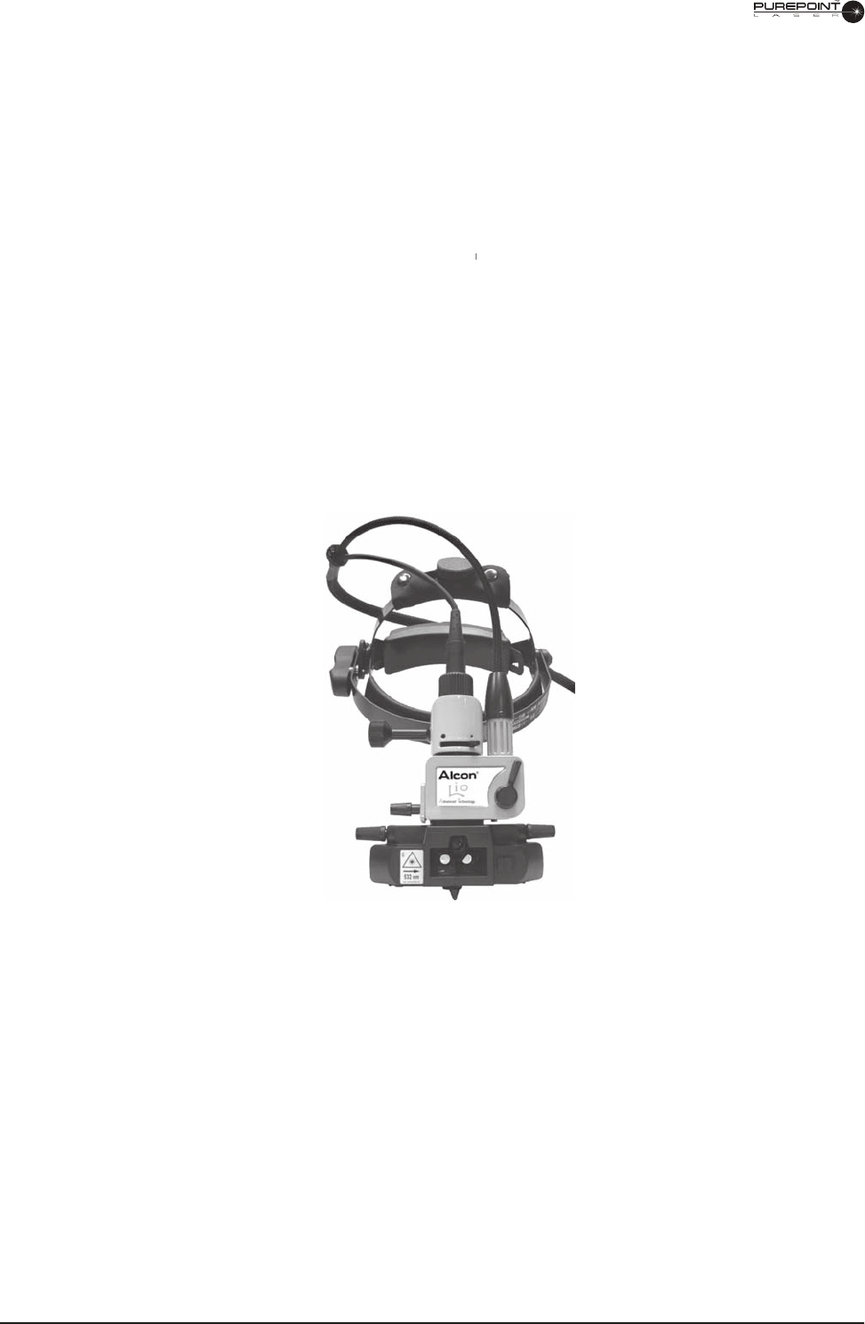
Figure 6-9 The Alcon
Laser Indirect Ophthalmoscope-Advanced Technology

8065751131 6.11
WARNINGS!
The head-worn Laser Indirect Ophthalmoscope (LIO-AT) is designed solely for examination
and treatment of the eye, particularly the retina.
Use only the illumination power supply provided with LIO-AT. It is specially designed for
medical applications.
Insure that the selection on the
PurePoint
™
front panel is LIO. It is the responsibility of the
™
front panel is LIO. It is the responsibility of the
™
operator to verify that the selection is correctly confi rmed.
The operator will have a colored** (pink) view through the Doctor Protection Filter due to
blocking of the 532 nm wavelength (green).
The operator must be careful to avoid potential secondary refl ections; therefore the room
used to treat the patient should be approved by a qualifi ed laser safety offi cer.
All personnel in the treatment room must wear protective eyewear (OD 4 or above at 532
nm) when the system is in “Standby” or “Ready” modes.
The laser delivery system is an integral part of the Alcon LIO-AT and is not designed to be
used with an observer. Never use a teaching or observation system in conjunction with the
LIO-AT. There is no eye protection provided for the observer.
Never treat a patient when the
PurePoint
™
Laser is connected to a service computer.
™
Laser is connected to a service computer.
™
Before each use of the headset, the operator must check the permanent Doctor Protection
Filter for scratches, breaks, or alterations. If there is any doubt, please call Alcon Technical
Services, and discontinue use of device.
There are potential hazards when inserting, steeply bending, or improperly handling of
the fi ber optic cable. Not following the recommendations of the manufacturer may lead to
damage to the fi ber or delivery system and/or harm to the patient or user.
Since the aiming beam passes down the same delivery system as the treatment beam,
it provides a good method of checking the integrity of the delivery system. If the aiming
beam spot is not present at the distal end of the delivery system, or its intensity is reduced
or it looks diffused, this a possible indication of a damaged or not properly working
delivery system. If there is any doubt, contact Alcon Technical Services.
The use of fl ammable anesthetics or oxydizing gases such as nitrous oxide (N
2
O) and
oxygen should be avoided. Some materials - for example cotton wool when saturated with
oxygen - may be ignited by the high temperatures produced in normal use of the laser
equipment. The solvents of adhesives and fl ammable solutions used for cleaning and
disinfecting should be allowed to evaporate before the laser equipment is used. There is
also danger of ignition of endogenous gases.
A qualifi ed technician must perform a visual inspection of the following components every
twelve months: warning labels, power cords, and fuses. In case of a defi ciency, do not use
the system; call Alcon Technical Services.
A qualifi ed technician must verify the LIO-AT performance by performing an LIO-AT
calibration, power output, and energy matrix test every twelve months to ensure the
LIO-AT is operating within specifi cations. See Section Four of this operator's manual for
instructions. If the LIO-AT is not operating within specifi cations, do not use the system;
call Alcon Technical Services.
A qualifi ed technician must check and record ground continuity and both polarities for
leakage current every twelve months to ensure they are within the applicable standards
(for example: EN60601-1/lEC601-1). If they are above the applicable standards, or 50%
above initial measurement, do not use the system; call Alcon Technical Services.
6.12
8065751131
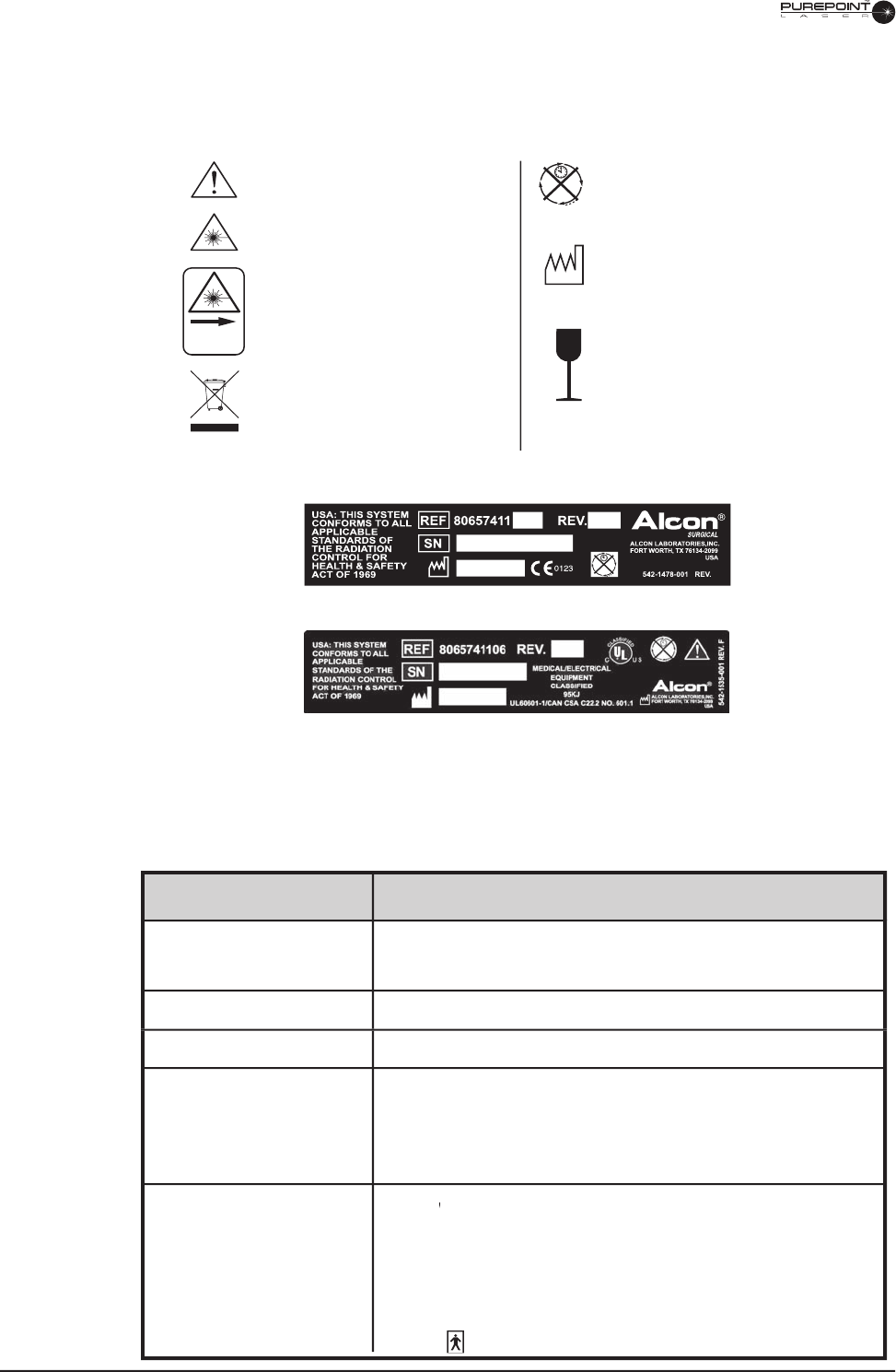
Alcon
LIO-AT Icons and Labels
The labels and icons shown in Figure 6-10 are found on the Alcon LIO-AT and are defi ned as
indicated.
Figure 6-10 Alcon LIO-AT Labeling
532 nm
542-1476-001REV
CE Identification Label
Refer to Operator's Manual
Laser Radiation
Laser Aperture
Use appropriate take-back
system (See Environmental
Considerations in this manual)
No Continuous Use of LIO-AT;
10 Minutes ON/20 Minutes OFF.
Manufacture Date
Fragile - Handle Laser Fiber
With Care
cUL-UL Identification Label
Table 6-3 Alcon
LIO-AT Technical Specifi cations
SPECIFICATION
Width: 22.0 cm (8.7 inches)
Length: 24.2 cm (9.5 inches)
Height: 20.0 cm (7.9 inches)
571 g (1.26 lbs.)
See Heine power supply documentation.
Operating: Temperature: 15º C≤ Tº ≤ 35º C
Relative Humidity: 10% to 90% with no condensation
Storage: Temperature: -40º C≤ Tº ≤ 70º C
Relative Humidity: 10% to 90% with no condensation
EyeLite
®
Laser complies with CE MDD requirements (CE 0123).
®
Laser complies with CE MDD requirements (CE 0123).
®
Not suitable for use in the presence of fl ammable anesthetic, oxygen, or
nitrous oxide.
System not protected against the ingress of water.
Class IIb,
IEC 601-1
CATEGORY
Dimensions
Headset Weight
Electrical characteristics
Environmental Limitations
Miscellaneous

8065751131 6.13
Alcon
LIO-AT Safety Features
• Labels on the instrument warn the operator about laser dangers.
• An On/Off (I/O) switch with indicator light controls the illumination power supply.
When the indicator light is ON, the illumination power supply is ON.
• A protective housing covers the laser source completely and the beam will only exit
through the LIO-AT exit window.
• A permanent Doctor Protection Filter on the LIO-AT headset protects the operator from
incidental refl ections of the laser beam. Prior to using the laser system, ensure that the
fi lter is in good condition and that it has not been damaged, displaced, or moved.
• An emergency switch located on the
PurePoint
™
console can be used to shut off power
™ console can be used to shut off power
™
to the laser. After using the emergency switch, pull it back to its initial position to restore
power and start the instrument.
General System Precautions
All personnel operating laser systems shall follow each of the general safety precautions
listed below.
• Never look into the laser beam.
• Restrict laser room access to people whose presence is required and who are familiar with
the laser precautions.
• The laser room should be clearly identifi ed with proper warning signs.
• Never direct the laser beam towards an opening.
• Never place any refl ecting object in the path of the laser beam, or direct the laser beam
toward objects that may refl ect light (such as surgical instruments).
• Turn the
PurePoint
™
Laser OFF when not in use.
™ Laser OFF when not in use.
™
• Turn the LIO-AT illumination power supply OFF when not in use.
• Only authorized personnel thoroughly familiar with the recommendations contained in
this manual may operate the LIO-AT. Any use of this laser system beyond the design
intentions may result in dangerous exposure to laser radiation.
• Familiarity and understanding the use and application of the Indirect Ophthalmoscope is
a prerequisite to using the LIO-AT.
Power Supply
For information on the desktop power supply (
Heine
For information on the desktop power supply (Heine For information on the desktop power supply (
EN 20-1) refer to the documentation
provided with the power supply.
Connecting the Alcon LIO-AT to the
PurePoint
™
PurePoint™
PurePoint
Laser
™ Laser
™
1. Connect the fi ber from the LIO-AT termination to the Laser Aperture connector on the
PurePoint
™
front panel.
™ front panel.
™
2. Attach the power cord from the LIO-AT to the power supply (see
Heine
EN 20-1
documentation) and switch on illumination.
CAUTION
Do not use the
Heine
standard desktop power supply EXTENSION cable
(PN X-00.99.207) on the LIO-AT.
6.14
8065751131
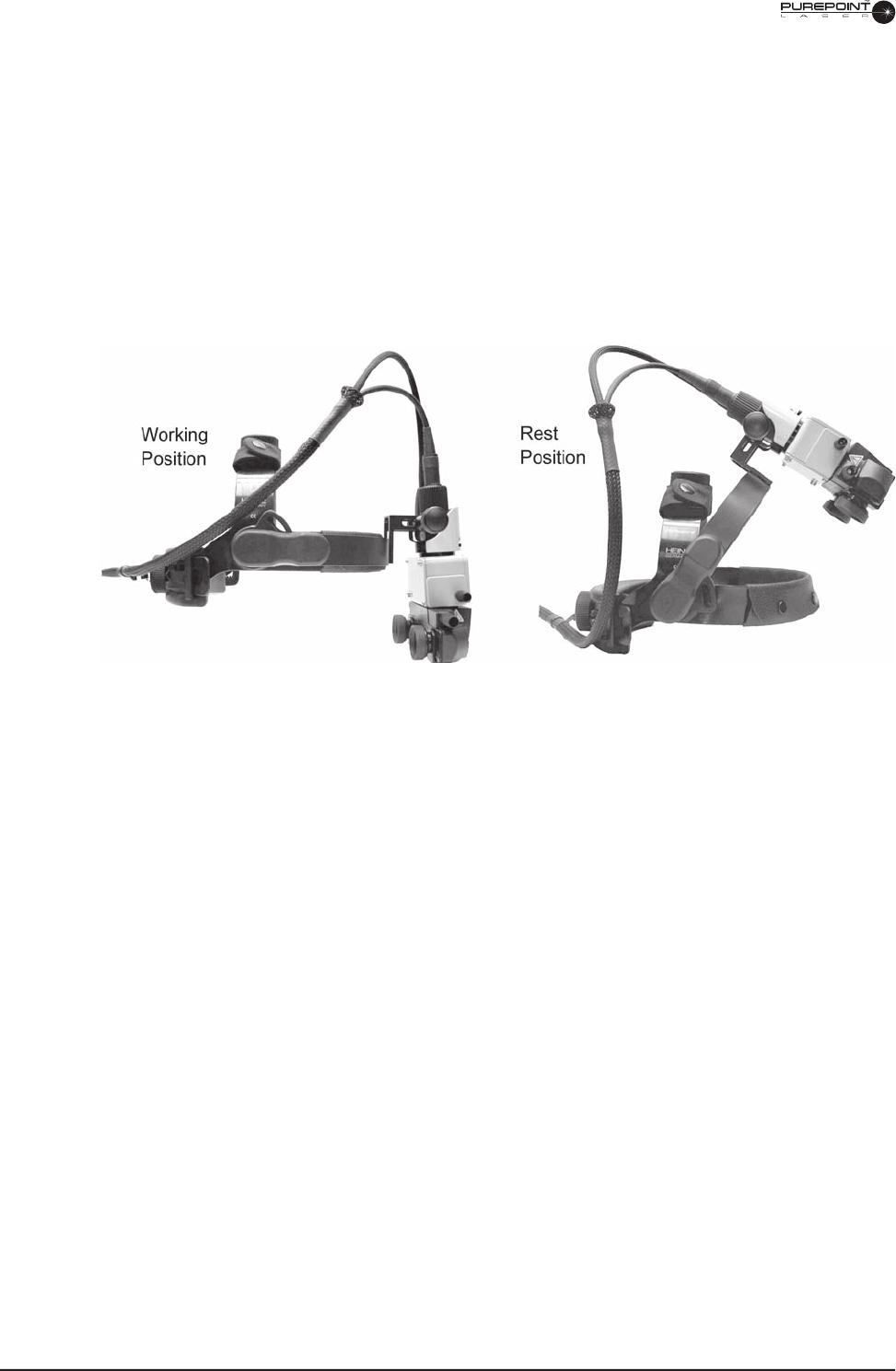
Using the Optics Overband
The pivoting overband allows the laser optics to be pushed up out of the operator's fi eld of
view (see Figure 6-11). It is locked in the end position and can only be released by pressing
the Overband Adjustment Knob.
To pivot the overband, press the Overband Adjustment Knob with the right hand and pivot
the overband into the desired position (up for the “rest” position and down for the “working”
position). When the unit is properly adjusted, the overband can be lowered into the same
pre-selected working position. Once set, changing the adjustments is required only if another
examiner uses the instrument.
Figure 6-11 Adjusting the LIO-AT Overband
Observation Optics Adjustment
1. Loosen the Observation Optics Adjustment Knob (see Figure 6-36) so that the
observation optics are free to move. The Observation Optics Adjustment Knob can be
unscrewed and reversed to the other side for left-handed operators. Remove dust cover
protecting delivery window.
2. Place the LIO-AT on your head and adjust the circumference and height using the
Circumference and Height Adjustment Knobs so that the headband is fi rmly positioned
but comfortable.
3. For convenience, use clothing clip to attach the fi ber/cable assembly to clothing.
4. Move the eyepieces as close as possible to your eyes and look at the light spot at a
distance of 30 cm. A small object (such as a pencil) held in front of the eyepieces at 30
cm must be clearly focused.
5. Using the Delivery Mirror Control Knob, adjust the optics so that the light spot
is centered vertically in your fi eld of view, then tighten the Observation Optics
Adjustment Knob.
6. If the light spot is not centered horizontally, adjust the headband left or right
accordingly.
7. Adjust the pupil distance setting by viewing the light spot alternately with the left eye
then the right eye, and sliding the eyepieces so that the spot is centered within your
fi eld of view.
8065751131 6.15
8. Remove the LIO-AT and look at the scale on the eyepieces to insure that the pupil
distance is symmetrical. If not, center the headset and readjust the eyepieces. Correct
adjustment of the optics is particularly important when examining small pupils.
Once set, changing the adjustments is required only if another examiner uses the instrument.
Controls for Observation and Illumination
The Aperture Lever (see Figure 6-12) allows you to choose between two different-sized
illumination fi elds. The choice of illumination fi eld size depends mainly on the size of the
patient’s pupil (the small illumination fi eld is the recommended setting). The positions of the
Aperture Lever for large and small illumination fi elds are marked with large and small black
dots, respectively.
The Convergence Control Knob provides synchronized adjustment of both examination and
illumination beams to suit the patient's pupil size. Wide convergence and parallax selection
allows for maximum stereopsis with large pupils. Narrow convergence and parallax selection
allows stereoscopic examination for small pupils.
NOTE: Use the small pupil setting and
narrowest convergence angle at the small illumination fi eld size setting; otherwise,
clipping (shadow) of the illumination fi eld will occur. The Convergence Control Knob
adjustment range is limited in the LIO-AT to 50% of the original
Heine
range to
accommodate for the laser beam delivery requirements.
The Delivery Mirror Control Knob can be rotated to move both the illumination beam and the
laser beam in the vertical plane.
CAUTION
Do not use the LIO-AT with the illumination power supply set at maximum intensity
for
more than 10 continuous minutes. The LIO-AT must be allowed to cool down at
least 20
minutes between uses. Use as little observation/illumination light as possible and
always switch power supply OFF after use.
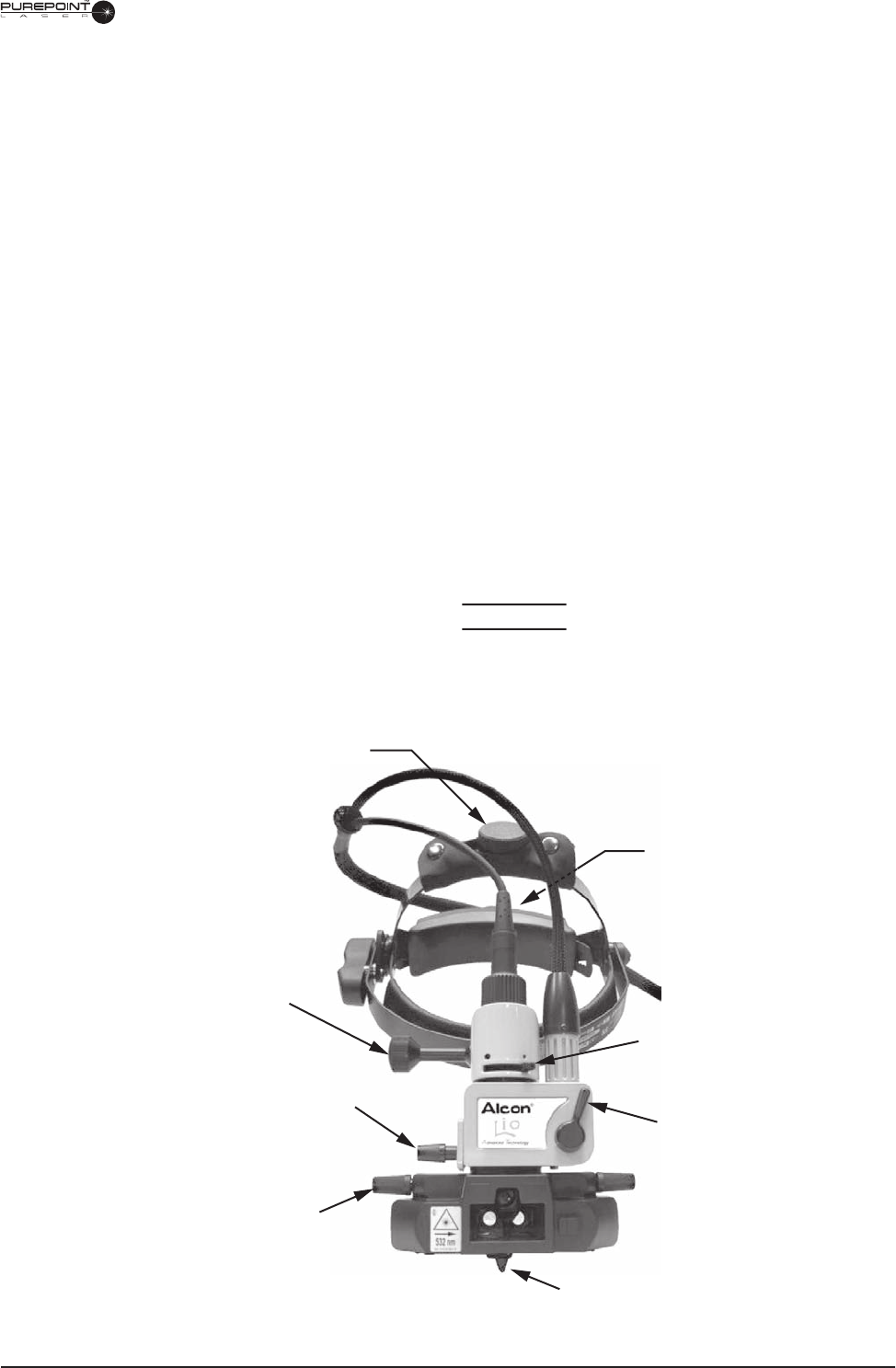
Circumference
Adjustment Knob
(on backside of band)
Observation Optics
Adjustment Knob
Laser Vertical
Adjustment Knob
Delivery Mirror
Control Knob
Height Adjustment Knob
Aperture Lever
Laser Spot Size Lever
Convergence Control Knob
Figure 6-12 LIO-AT Controls and Adjustments
6.16
8065751131
Using the Alcon LIO-AT for Observation
If the LIO-AT is used for illumination purposes only, the laser fi ber does not need to
be connected to the
PurePoint
™
Laser
.
Note: Put dust cover on fi ber termination to
protect fi ber when not connected to
PurePoint
™
PurePoint™
PurePoint
Laser
.
Laser.Laser
1. Turn the illumination power supply on.
2. Adjust the light intensity with the power supply illumination control knob.
Using the Alcon LIO-AT for Laser Treatment
Using the system in this mode enables photocoagulation with the LIO-AT.
WARNING!
All the personnel in the room during the operation must wear protective safety
eyewear with a minimum optical density OD 4 to fi lter 532nm radiation.
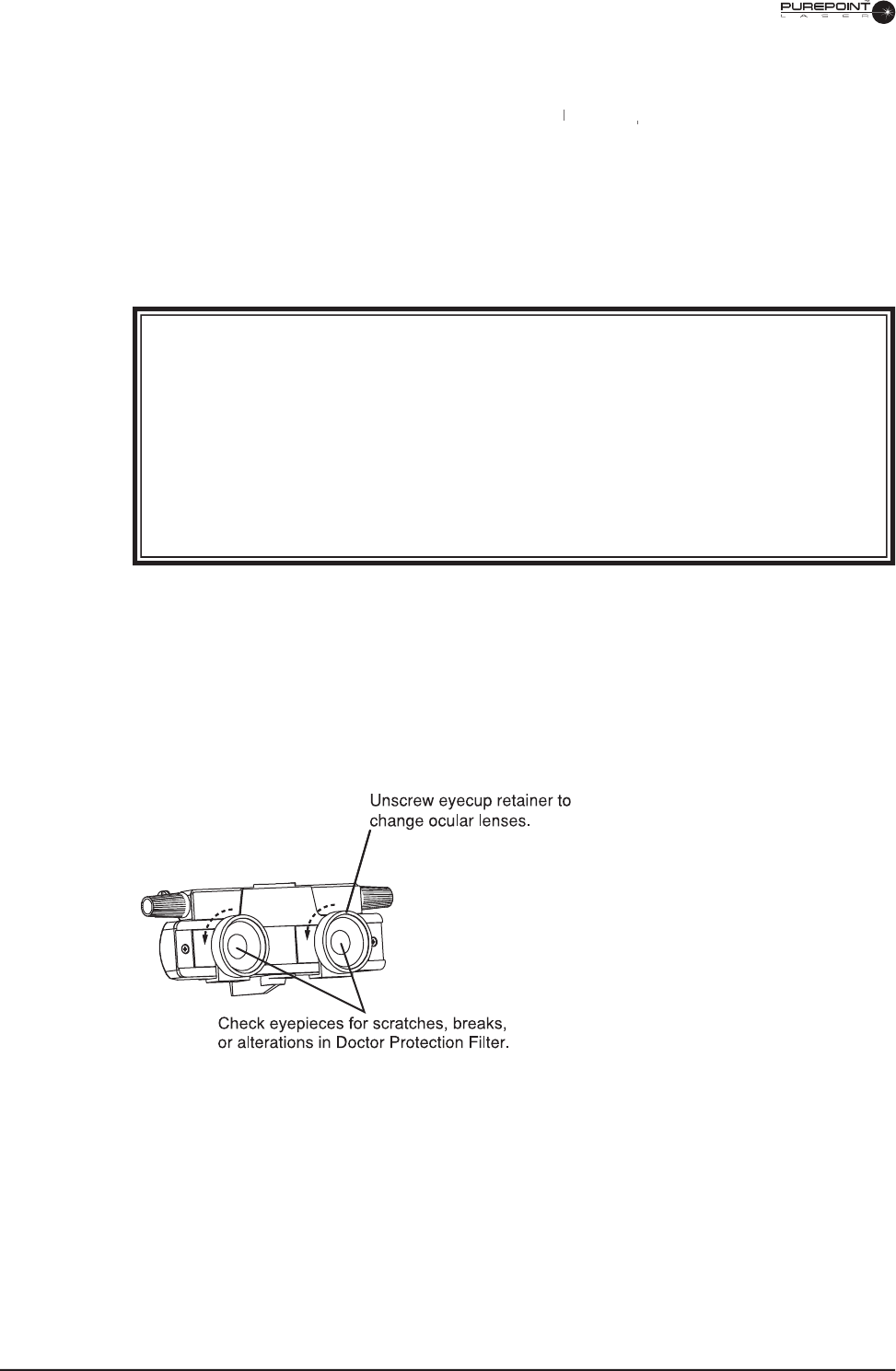
Before each use of the headset, the operator must examine the permanent Doctor
Protection Filter for scratches, breaks, or alterations by looking through the
ocular lens. If there is any doubt, discontinue use of device and please call Alcon
Technical Service.
NOTE: The LIO-AT is shipped with +2 diopter ocular lenses installed. These may be
changed with 0 (zero) diopter lenses.
1. If desired, change the ocular lenses by unscrewing the eyecup retainer in the
counterclockwise direction, change each lens, and replace the eyecup retainers. Ensure
that the new lenses are clean, i.e. no fi ngerprints or debris. Refer to the LIO-AT
maintenance section for cleaning instructions.
Figure 6-13
Eyecup Retainers and Ocular
Lens on the Alcon LIO-AT
2. Turn the
PurePoint
™
console power ON and make the appropriate selections as
specifi ed in Operator's Manual.
3. Turn the LIO-AT Illumination power supply ON.
4. Select the appropriate illumination fi eld size by toggling the illumination aperture lever
to the desired setting.
5. Adjust the illumination intensity using the power supply illumination control knob.

8065751131 6.17
6. Set the power below the nominal titration level by turning the Power Adjust knob on
the
PurePoint
™
console counterclockwise. If the power parameter is not set below
™ console counterclockwise. If the power parameter is not set below
™
the nominal titration level, the message “Set Power < xxxx mW” will appear on the
display.
7. If necessary press the Reset key to reset the shot counter to 0.
You can now adjust exposure time, aiming beam power, and treatment beam power.
8. Select exposure time by pressing the Exposure Time Adjustment arrow keys. If
Continuous Wave mode is selected, “Mode: Continuous” is displayed.
WARNING!
Verify that all personnel are wearing protective eyewear (OD 4 or above at 532 nm)
as soon as the system is in Standby/Ready mode, as well as during treatment.
NOTE: It is not recommended to use exposure times longer than 2 seconds in CW
(Continuous Wave) mode. Depending on the thermal load, the system may
shut down prior to the footswitch being released. A message will appear on the
display indicating this condition.
9. Select the aiming beam intensity by turning the Aiming Beam Intensity knob.
WARNING!
Do not attempt treatment if aiming beam is not present. Patient injury may occur.
10. Turn the Power Adjust knob to set the desired treatment power.
11. Select the laser spot size using the Laser Spot Size Lever (see Figure
6-12). The
positions of the Laser Spot Size lever for large (approximately 1mm) and small
(approximately 0.5mm) laser spot sizes are marked with large and small black dots on
the right side of the box, respectively. The change of laser spot size from large to small
results in approximately four times increase in irradiance within the treatment area,
provided that laser power was not adjusted.
It is recommended to adjust laser power each time the Laser Spot Size Control setting
is changed. Start with a low power, short duration pulse then increase until the desired
coagulation result is achieved.
WARNING!
If unsure which settings are required, select a low power, short duration, and large
laser spot size. Failure to properly adjust delivered energy may lead to patient
injury.

6.18
8065751131
12. Press the Standby/Ready key on the front panel. The green Standby LED turns OFF,
and the red Ready LED illuminates.
NOTE: The footswitch must be released to proceed to Ready mode. If the footswitch
is depressed during power-up or while in Standby mode, “Release footswitch”
is displayed. Release footswitch and proceed.
13. Use the Laser Vertical Adjustment Knob (see Figure 6-12) on the laser delivery
adaptation to aim the laser at the desired location within the illumination fi eld.
14. Press the footswitch when ready to fi re. The system will emit a 4 millisecond beep each
time the laser fi res. If the footswitch is not pressed within 2 or 10 minutes starting from
entry into “Ready” mode, the system emits one beep and switches to “Standby” mode.
NOTE: The aiming beam is off during treatment beam exposure, except in repeat mode.
15. Repeat the fi ring procedure as often as necessary, making adjustments to power output
and duration as appropriate to complete the treatment session.
16. When the treatment is completed, release the footswitch and press the Standby/Ready
key. The green Standby LED illuminates and the system is placed in “Standby” mode.
NOTE: You can disable both treatment and aiming lasers by pressing the Laser ON/
OFF switch. When turning the switch ON again, the system will default to the
last terminal selection used before shutdown with the exception that LIO will
default to Endo. Parameters shall be restored to the selected terminal.
Turn Off Sequence
1. Turn the Power Adjust knob to the minimum position.
2. Turn the key to the OFF (O) position and, for safety reasons, remove the key.
NOTE: The emergency switch on the front panel must only be used in case of
emergency. After using the emergency switch, pull it back to its initial position
to restore power and start the instrument.
3. Place the power switch on the rear of the system in the OFF (O) position.
NOTE: Between patients you can use the LASER ON/OFF switch to disable the
treatment and aiming beams. The cooling system remains active in this mode.
4. Place the illumination power switch to the OFF (O) position.

8065751131 6.19
ALCON
LIO-AT MAINTENANCE
This section contains information for basic care and maintenance of the instrument. If a
problem occurs on the instrument, call the Alcon Technical Services department and give
details of the breakdown circumstances and effects. From these elements, a technician will
evaluate the problem and determine the maintenance requirements.
WARNING!
Maintenance on any part of the laser system must be performed with the laser
off and the main power plug disconnected.
Checking System Appearance
The condition of the system hardware components must be checked periodically to identify
any fault which might cause incorrect operation of the system.
• Chassis appearance.
• Operation of controls and indicators.
• State of the fi bers and connecting cables.
• Check permanent Doctor Protection Filter for damage; i.e., scratches and cracks.
Any damaged hardware must be replaced. Contact your Alcon Technical Service
representative.
CAUTION
Care and cleaning operations must be performed with the instrument turned off and
power disconnected.
Headset Care and Maintenance
• The eyepieces and the glass in front of the binocular assembly can be cleaned with a soft
cloth (dipped in alcohol if necessary).
• The cushions for forehead and nape can be removed for wiping with soapy water.
• The rest of the instrument can be cleaned with a soft cloth dipped in alcohol. Under no
circumstances should cleaning fl uids be used.
Storage
The LIO-AT should be stored either on the Headset Stand or in the Storage Case when not in
use to prevent inadvertent damage to the headset or cables.
6.20
8065751131
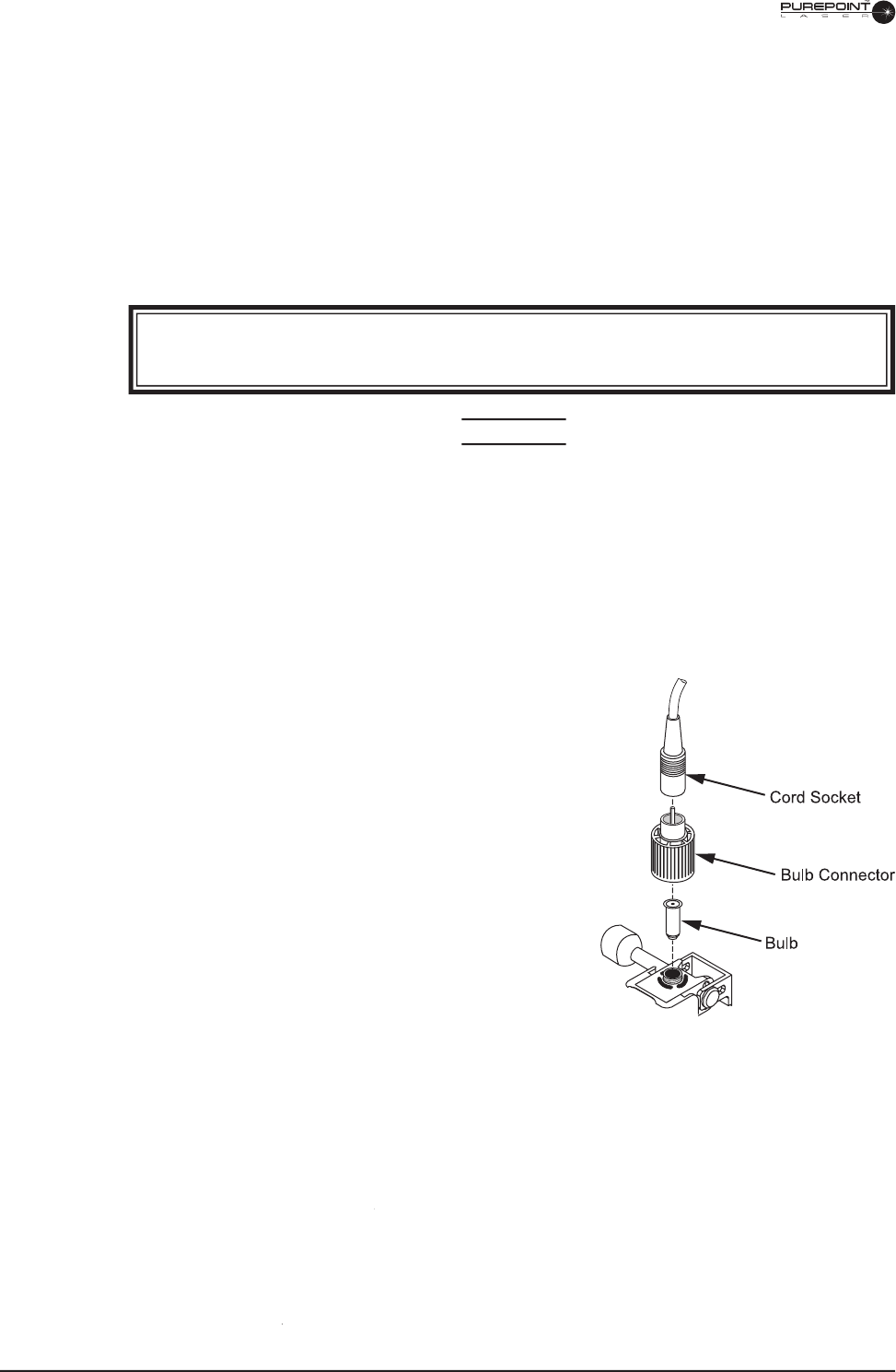
Changing The Illumination Bulb
1. Ensure that power switches on the
PurePoint
™
Laser
and illuminator power supply are
in the OFF (O) position.
2. Disconnect power cord from power source.
3. Pull the cord socket away from the bulb connector (see Figure 6-14).
4. Unscrew and remove the bulb connector, then pull the bulb out of the socket.
WARNING!
The bulb and bulb connector may be hot, and can burn your fi ngers.
CAUTION
Do not touch the glass part of the new bulb directly with your fi ngers. Oil from fi ngers
can dramatically reduce bulb life.
5. Clean the new bulb with a soft, clean cloth.
6. Insert the new bulb so its locating pin engages in the housing slit.
7. Rest the bulb connector on the base of the bulb and fi rmly screw it in.
8. Re-connect the cord socket.
Figure 6-14
Alcon
LIO-AT Bulb Replacement
Calibration
Alcon Surgical recommends that the Laser Indirect Ophthalmoscope be calibrated on an
annual basis as an integral part of the laser system with which it is used. Refer to Section
Four for calibration information.
ALCON LIO-AT SPARE PARTS AND ACCESSORIES
Bulb 6V
. . . . . . . . . . . . . . . . . . . . . .
P/N 542-1119-001
Laser Protective Eyewear
. . . . . . . . .
Laser Protective Eyewear . . . . . . . . . Laser Protective Eyewear
P/N 8065750107
28 D Lens
. . . . . . . . . . . . . . . . . . . . .
P/N 8065750158
20 D Lens
. . . . . . . . . . . . . . . . . . . . .
P/N 8065-6879-01
+2 D Ocular Lens
. . . . . . . . . . . . . . .
P/N 301-361
0 D Ocular Lens
. . . . . . . . . . . . . . . .
P/N 301-362
Headset Stand
. . . . . . . . . . . . . . . . . .
Headset Stand . . . . . . . . . . . . . . . . . . Headset Stand
P/N 8065750891

8065751131 7.1
SECTION SEVEN
INDEX
TO BE DETERMINED...

7.2
8065751131
LAST PAGE OF THIS SECTION
8065751131LAST PAGE OF THIS SECTION 8065751131
THIS PAGE INTENTIONALLY BLANK