Alcon Research PUREPT1 PurePoint User Manual NGL Book 1 indb
Alcon Research Ltd. PurePoint NGL Book 1 indb
Contents
- 1. User Manual part 1 of 5
- 2. User Manual part 2 of 5
- 3. User Manual part 3 of 5
- 4. User Manual part 4 of 5
- 5. User Manual part 5 of 5
User Manual part 3 of 5

8065751131 3.1
SECTION THREE
OPERATING INSTRUCTIONS
INTRODUCTION
This section details the recommended setup and operation for the
PurePoint™
Laser.
These procedures may be modifi ed to conform to hospital requirements and practices
as you become experienced in using the system. However, the operational checks that
are performed at various points in the setup procedure to verify instrument operation
must be performed exactly as indicated.
WARNING!
Noncompliance with the instructions contained in this manual may result in
operator injury.
The following procedures (Initial Setup, System Connections, System Power Up, and
Operation) cover preparation for laser treatment involving Slit Lamp, Endoprobe/
Aspirating Endoprobe/Illuminated Endoprobes, or LIO usage.
Any questions pertaining to setup and checkout procedures should be directed to your
Alcon Technical Services representative.
1 INITIAL SETUP
WARNING!
To avoid potential secondary reflections, a qualified laser safety officer should
approve the room used to treat the patient.
1.1 Position the instrument for surgeon’s comfort and preference. Refer to Section
One for "Recommended Laser Room Layout."
1.2 Verify that no combustible materials are adjacent to the laser and its delivery
systems.
2 SYSTEM CONNECTIONS
2.1 Connect footswitch to Footswitch connector.
2.2 Connect Remote Interlock to REMOTE Interlock connection.
2.3 Plug in the power cord to the power cord socket and to a properly grounded
main power outlet (220-240 VAC, 10A minimum; or 100-120 VAC, 15A
minimum).
2.4 Ensure all Doctor/Observer protection fi lters are installed in the optical path of
the slit lamp or microscope, and connected to the Doctor Protection Filter ports
on the rear panel (see Figure 3-1).
2.5 Verify that the power switch on the rear panel is in the ON position.
2.6 Insert key into keyswitch on front panel. Leave in the OFF position.

3.2
8065751131
WARNINGS!
The Slit Lamp must be equipped with a special Alcon Slit Lamp adaptation. This
adaptation is available for many of the existing Slit Lamps. (Reference section
six for list of adaptations to be used with existing slit lamps.) If peripherals are
not correctly connected and confirmed by the operator, the operator and patient
will be exposed to hazardous radiation.
Refer to Section Six for instructions on installing the Doctor Protection Filter.
The operator may have a colored view through the Doctor Protection Filter due
to blocking of the green 532 nm wavelength light. Newer filters will have less
color blocking. It is the operator’s responsibility to properly install the Doctor
Protection Filter. Alcon shall not be held liable for problems caused by improper
installation of the Doctor Protection Filter.
If a tethered manual Doctor Protection Filter is in the “not engaged” position the
prompt on the
PurePoint™
LCD display must read “Please engage Dr. Filter.” If
not, the operator must discontinue using the system and notify Alcon Technical
Services for assistance.
When using beam splitter accessories, the ocular stereo microscope head must first
be attached to the beam splitter (the beam splitter accessories are attached to the
beam splitter on the protected side of the Doctor Protection Filter assembly); the
beam splitter is then attached to the permanently installed Doctor Protection Filter.
Improper installation could cause injury to the operator and/or the patient.
It is the user's responsibility to ensure that non-RFID probes are correctly
identified.
Do not use assessories with a fiber or connector that have been compromised.
2.7
SLIT LAMP CONNECTION:
Connect the fi ber optic connection from the slit
lamp zoom to a laser fi ber port on the front panel (see Figure 3-1)
NOTE: When removing the fi ber of a slit lamp terminal or an LIO terminal, be
sure to secure the dust cover on the front panel fi ber port.
2.8
LIO CONNECTION:
2.8.1 Connect LIO fi ber to a laser fi ber port on the
PurePoint™
front panel.
2.8.2 Insert LIO power cord into LIO illuminator power port on front panel.
WARNING!
Endoprobes are for single-use only. Microbial or prion infection may occur if
re-used.
2.9
ENDOPROBE CONNECTION:
Connect fi ber to a laser fi ber port on the
PurePoint™
front panel.
NOTE: Refer to section six for additional information on setting up and using
these accessories.
2.10 Ensure Red Emergency Switch is pulled out. Press only in case of emergency.
8065751131 3.3
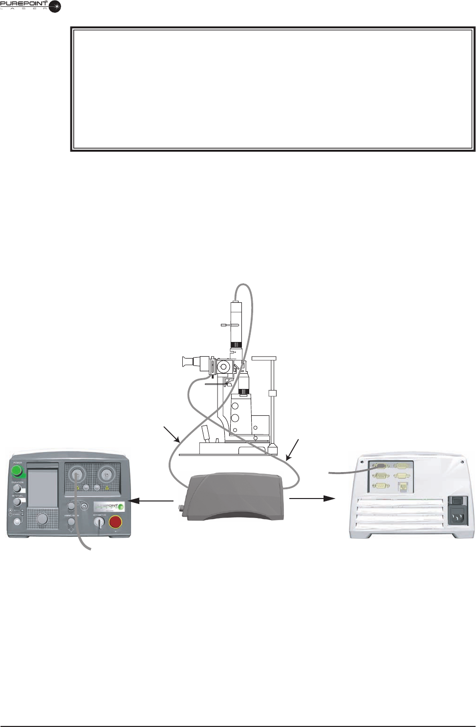
Figure 3-1 Slit Lamp Connections
WARNINGS!
Performing procedures other than those specified herein may result in hazardous
laser radiation exposure.
Everyone present in the treatment room must wear protective eyewear O.D. 4 or
above at 532 nm when the system is in standby as well as during treatment.
Possible explosion hazard if used in the presence of flammable anesthetics or
other gas mixtures.
Doctor Protection Filter
Electrical Connection
Fiber Optic
Connection
3.4
8065751131
3 SYSTEM POWER UP AND SET UP
NOTE: Be sure to read all prompts on the display.
3.1 Turn the key to the ON (horizontal) position. Figure 3-2 shows the sequence of
screens displayed during initialization.
• The front panel display illuminates the background LED’s and initializes the
LCD screen.
• If no laser fi ber is connected to a port, a prompt to insert a probe is displayed
until one is connected.
During initialization of the system, the delta between the set point and actual
temperature of the laser engine is shown as it approaches nominal operating
temperature. The user can perform the following setup operations during
initialization: inserting probes, inserting LIO illumination power, set laser parameters
if an identifi ed probe is inserted, and view or change system settings.
NOTES: If the optical fi ber is not connected, the aiming beam will not turn on
and the system will continue to display: “Please Insert Probe .”
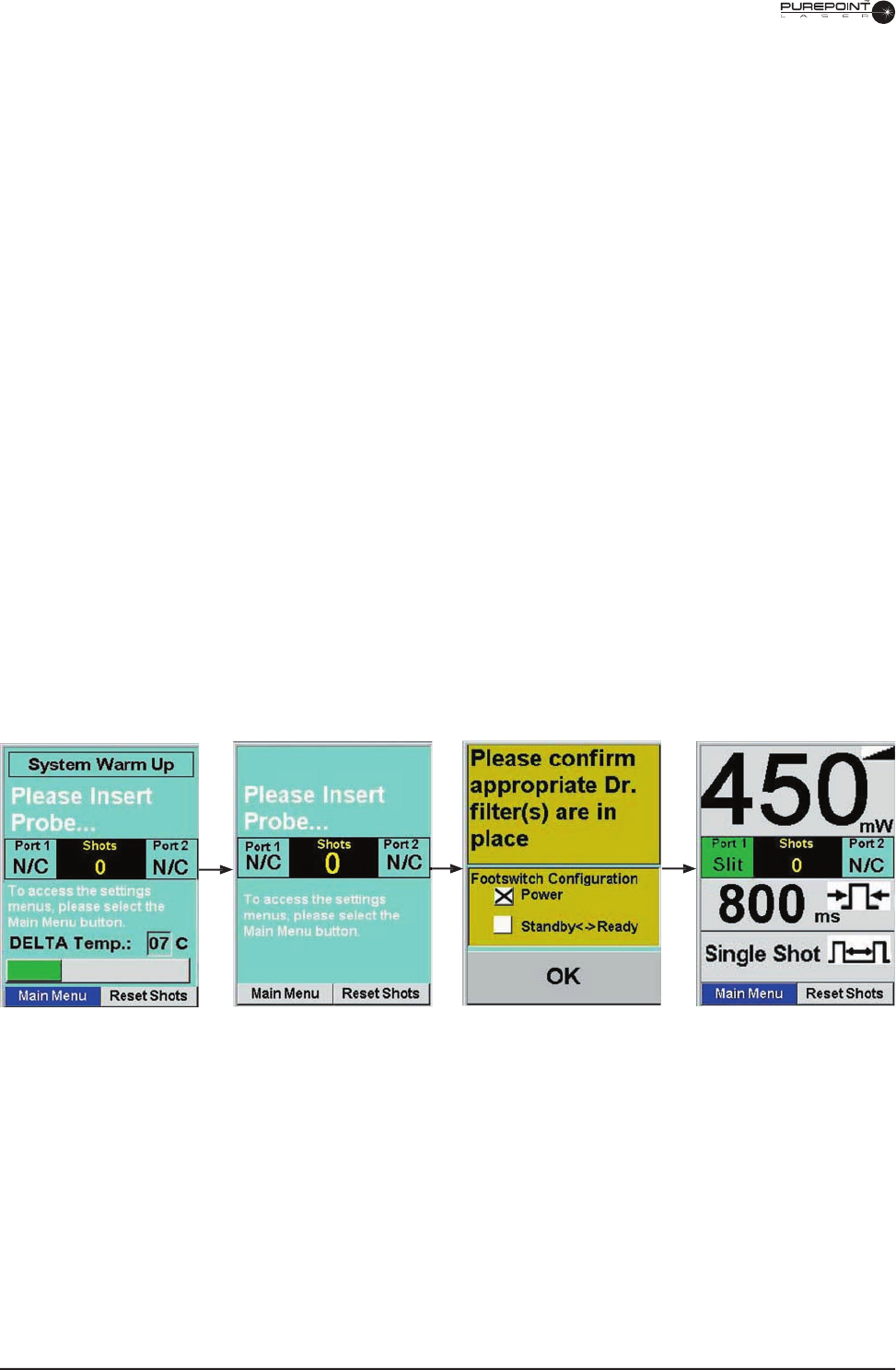
Display while initializing,
nothing plugged in the front
panel. No laser parameters
are set.
An identifi ed slit lamp fi ber has
been plugged-in and system
requests Dr. fi lter confi rmation.
Current footswitch
confi guration is displayed.
Fully initialized display
(Operating Display) with gray
background that indicates
Standby mode.
Figure 3-2 Display During Initialization
Display after warmup is
complete, system requests
probe to be inserted.

8065751131 3.5
3.2 Verify Presence of Dr. Filter(s). (For slit lamp and endo selections.)
When the message “Verify appropriate Dr. Filters in viewing devices” appears,
verify that the appropriate Dr. Filters are placed in all viewing devices.
Next, highlight “Connected” or “Not Connected” by turning the settings knob
and press when the desired response is highlighted. If “Not Connected” is
selected, the laser cannot be fi red.
• If the Doctor Protection Filter is not in place, install it as described in
Section Six, and then select “Connected” from the display using the settings
knob.
• If a tethered Doctor Protection Filter is in place but not engaged, engage the
Doctor Protection Filter by rotating lever clockwise until engaged/stopped.
WARNING!
It is the operator’s responsibility to properly install the Doctor Protection Filter.
The operator may have a colored view through the Doctor Protection Filter due to
blocking of the 532 nm wavelength (green). Newer filters have less color, making
the view more true to the actual colors.
NOTE: The default values for the following parameters can be changed as
described in Section Two of this manual.
3.3 Set the shot count to zero by turning the Menu knob until "Reset Shots" is
selected, then push the knob in to zero the count. To change from Shot Count to
Total Energy, go to the Treatment Totals Options screen (Main Menu\Settings\
Treatment Totals Options).
WARNING!
If unsure which settings are required, select a low power, short duration, and large
spot size. Failure to titrate delivered energy may lead to patient injury.
3.4 Select the desired port by pressing the associated Port Selection button.
3.5 Set the desired treatment power by turning the Power knob.
3.6 Set the desired pulse duration of the laser shot by turning the Pulse Duration
knob. If Continuous Wave mode is selected, the letters CW are displayed instead
of a number.
NOTE: It is not recommended to use exposure times longer than 2 seconds
in CW(Continuous Wave) mode. Depending on the thermal load, the
system may shut down prior to the footswitch being released. A message
will appear on the display indicating this condition.

3.6
8065751131
3.7 Set the desired inter-pulse time by turning the Inter-Pulse Time knob to the
desired setting in Repeat mode. To select Single Shot mode press the knob in or
turn the knob clockwise past the maximum 1 second inter-pulse time. In Single
Shot mode, the footswitch must be depressed for each shot. In Repeat mode, the
shots are fi red in a regular sequence while the footswitch is depressed and stops
when the footswitch is released.
3.8 Set the aiming beam intensity to the desired level by turning the Aiming Beam
Intensity knob.
WARNING!
Do not attempt treatment if aiming beam is not present. Patient injury may
occur.
NOTES: The footswitch must be released to proceed to Ready Mode. If the
footswitch is depressed during power-up or when switching from
Standby to Ready mode, the “Release Footswitch” message is
displayed.

8065751131 3.7
4 NORMAL OPERATING PROCEDURE
WARNING!
In the event of a system malfunction, press the Emergency Switch to immediately
disable the system.
After completing Power Up and Set Up Sequence, proceed as follows for normal
operation.
4.1 Ensure that all personnel are wearing protective eyewear, OD 4 or above at
532nm.
4.2 Slit Lamp and LIO Set Up
• If using a Slit Lamp, adjust the intra-pupillary distance and the
biomicroscope oculars focus so that the image is clear. Have the patient sit
in front of the Slit Lamp with his chin and forehead on the head rest. Target
the red aiming beam on the area to be treated and select the beam diameter
for the treatment.
• If using the LIO, adjust the intra-pupillary distance on the headset so that the
image is clear. Target the red aiming beam on the area to be treated.
4.3 Go to Ready mode by pressing the Standby/Ready Mode button on the front
panel or, if the multifunction footswitch setting is set to "Power and Ready <->
Standby," press and hold the right side switch until a tone sounds (1.5 seconds).
The Standby LED turns off, and the Ready LED blinks on and off during
transition. After 2 seconds, the background of the initialized display turns green,
indicating that the laser is ready to fi re. Figure 3-3 show the screen transition
from Standby to the Ready Mode.
If the multifunction footswitch setting is set to "Power and Ready <-> Standby"
or "Power Control Only," then the side switches can be used to increase (left
switch) or decrease (right switch) the laser power. In "Power and Ready <->
Standby," the side switches must be pressed less than 1.5 seconds to change
power. Pressing the right side switch longer than 1.5 seconds causes the system
to go to Ready mode, while pressing the left side switch longer than 1.5 seconds
causes the system to go to Standby mode.
WARNINGS!
Laser is ready to fire. Ensure the correct port and energy delivery settings are
selected each time the system is brought to the Ready mode.
3.8
8065751131
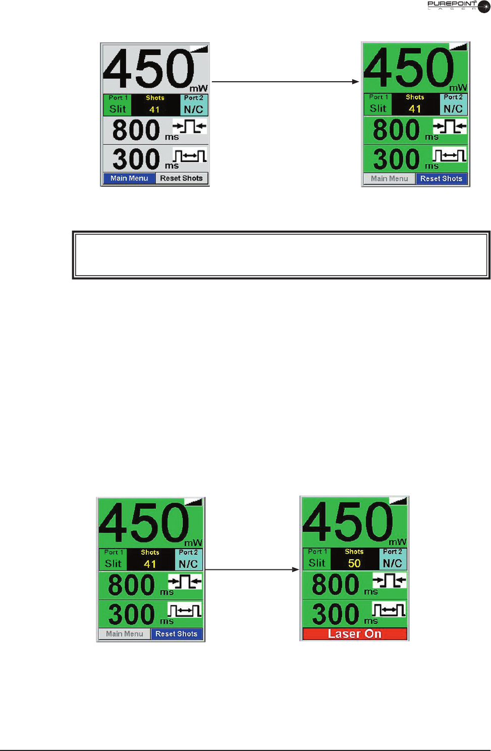
Ready State
Footswitch depressed;
bottom menu changes to
red background with "Laser
On" displayed; shot count is
increased.
Figure 3-4 Transition from Ready State to Laser On
Figure 3-3 Transition from Standby to Ready Mode
Standby Mode
Ready button pushed,
display blinks from
green to gray for 2
seconds
Ready Mode
WARNING!
Do not proceed if aiming beam does not turn on.
4.4 Press the footswitch when ready to fi re. The system emits a tone each time the
laser fi res. Figure 3-4 shows the display transition from Ready State to Laser
On. If the footswitch is not pressed within a period selected by the user from
entry into ready mode, the system switches back to Standby mode.
NOTE: The aiming beam turns off when the treatment beam fi res, except in
Repeat Mode.

8065751131 3.9
Figure 3-5 Transition from Laser On to
Standby because of a Warning
4.5 Repeat the fi ring procedure as often as necessary, making adjustments to power
output and duration as appropriate to complete the treatment session.
If the system transitions back to Standby mode because of a warning condition, the
parameters section color is changed and a warning message is displayed as shown in
Figure 3-5. This mode change will occur if any of the following events occurs while
the laser is fi ring:
• Standby/Ready button pushed.
• Footswitch unplugged.
• Laser fi ber disconnected from
selected port.
• Remote Interlock disconnected
port.
• Dr. Filter connected, disconnected,
or disengaged.
• System fault.
To resume normal operation,
perform the action(s) displayed in
the warning message.
4.6 When the treatment is completed, release the footswitch and press the Standby/
Ready key. The Standby LED illuminates and the system is placed in standby
mode.
5 TURN OFF SEQUENCE
5.1 Turn the key to the OFF (O) position and, for safety reasons, remove the key.
NOTE: The emergency switch on the front panel should only be used in an
emergency. After using the emergency switch, pull it back to its initial
position to restore power and start the instrument.
5.2 Place the power switch on the rear of the system to the OFF (O) position.
3.10
8065751131
6 CHANGING THE SYSTEM SETTINGS
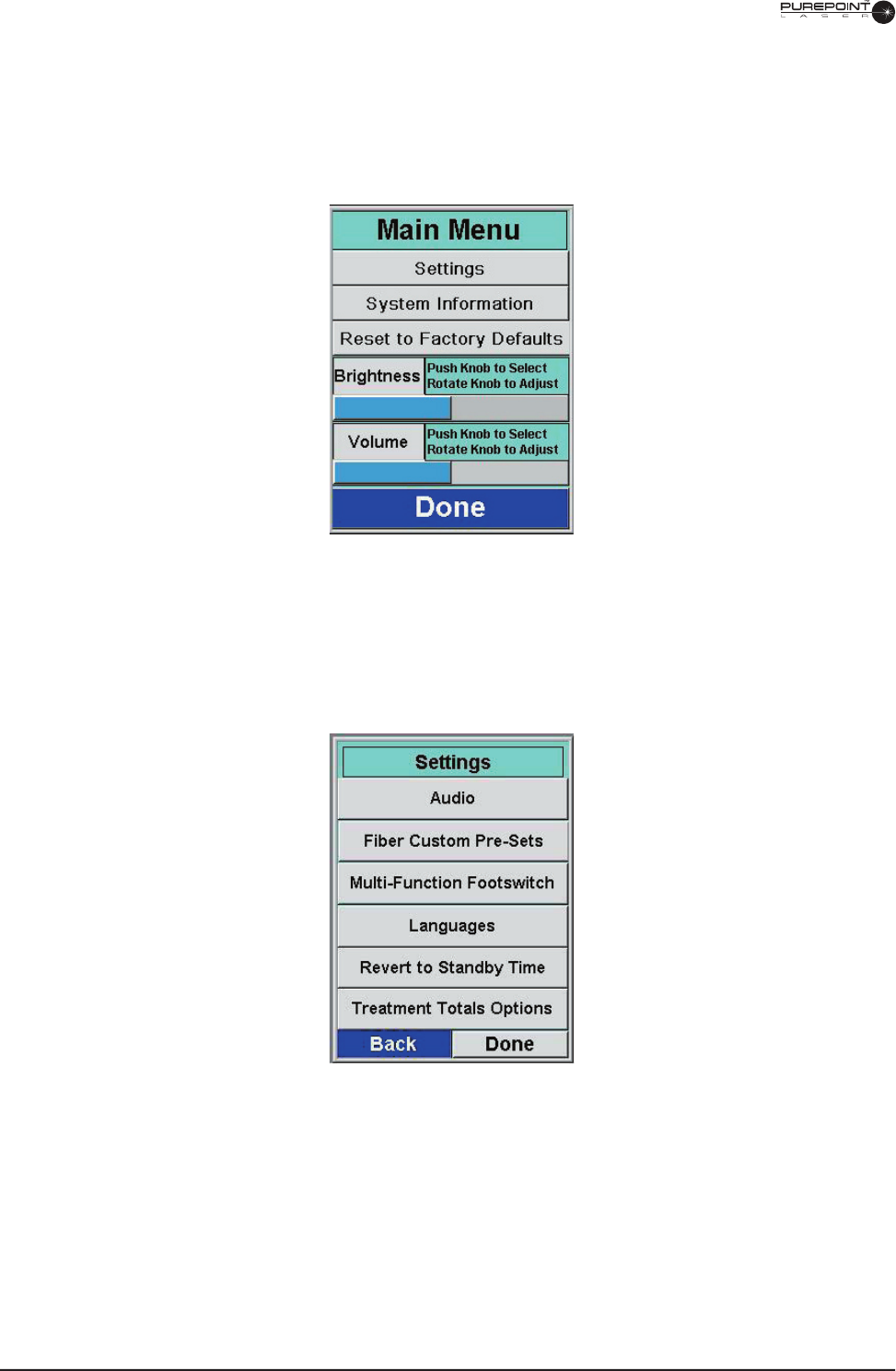
6.1 To access the Settings menu (system must be in Standby mode), turn the Menu
knob until "Main Menu" is highlighted then push the Menu knob to select. The
Main Menu is displayed as shown in Figure 3-6.
Figure 3-6 Main Menu
6.2 Turn the Menu knob until "Settings" is selected then press the Menu knob. The
Settings menu is displayed as shown in Figure 3-7.
Figure 3-7 Settings Menu
6.3 Turn the Menu knob until the desired setting is selected then press the Menu
knob. Refer to Section Two for a detailed description of each setting screen.
6.4 When setting changes are complete, select "Back" to return to the Settings menu
or "Done" to go back to the Standby screen.
8065751131 3.11
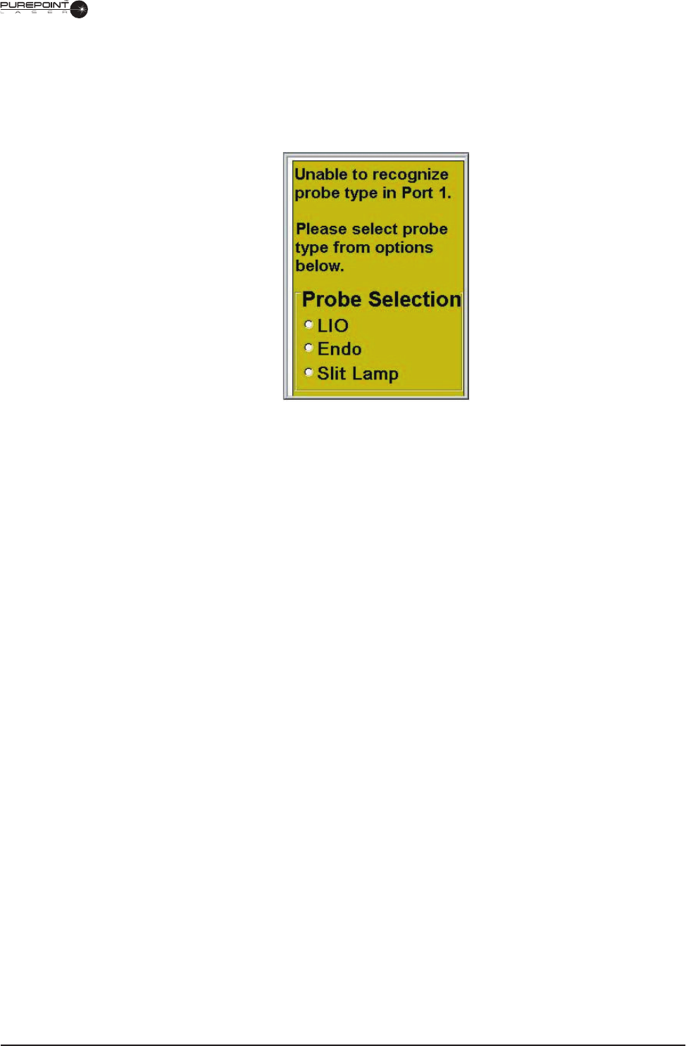
7 IDENTIFYING UNRECOGNIZED PROBES
If a probe without an identifying RFID tag is connected to the system, a message
appears stating that the system is unable to recognize the probe and prompts the user
to select a probe type (see Figure 3-8).
Figure 3-8 Unidentifiable Probe Display
7.1 Using the Menu Knob, select the type of probe connected to the system. The
system then applies the factory settings for that type of probe. These settings
may be changed in the Fiber Custom Presets display from the Main Menu.
If two unidentifi ed probes are connected when the when the system is turned on,
the display appears for Port 1, which is selected by default. The probe in Port
2 will not require identifi cation until the port is selected. If a probe is inserted
in Port 2 before one is inserted in Port 1, then the Port 2 probe will be the fi rst
selected for identifi cation.
If the laser is in Firing mode and an unidentifi ed probe is connected to the other
port, the Unidentifi ed Probe display will not appear until the user has stopped
fi ring the laser and the port is selected.

3.12
8065751131
LAST PAGE OF THIS SECTION
8065751131
LAST PAGE OF THIS SECTION
8065751131
THIS PAGE INTENTIONALLY BLANK