Alcon Research PUREPT1 PurePoint User Manual NGL Book 1 indb
Alcon Research Ltd. PurePoint NGL Book 1 indb
Contents
- 1. User Manual part 1 of 5
- 2. User Manual part 2 of 5
- 3. User Manual part 3 of 5
- 4. User Manual part 4 of 5
- 5. User Manual part 5 of 5
User Manual part 4 of 5

8065751131 4.1
INTRODUCTION
This section of the manual is designed to inform the operator of basic care and
maintenance of the instrument. It is recommended to verify the calibration annually.
In the event that recalibration is required, it is also recommended that the procedure
to recalibrate the system be performed by Alcon Technical Services personnel. If
a problem occurs on the instrument, call the Alcon Technical Services department
and give details of the circumstances and effects. From these elements, a specialized
technician will evaluate the problem and determine the maintenance requirements.
WARNINGS!
Maintenance on any part of the laser system must be performed with the laser
off and the main power plug disconnected.
When keyswitch power is on, all individuals in the laser room must wear laser
protective eyewear, OD 4 or above at 532 nm.
CAUTION
There are no operator replaceable parts other than the fuse. Contact Alcon Technical
Services for all servicing issues.
Care and Cleaning
WARNING!
A qualified technician must perform a visual inspection of the following components
every twelve months:
• Warning labels (see Section One)
• Power Cord
• Fuses
In case of a deficiency, do not use the system; call Alcon Technical Services.
A qualified technician must check ground continuity and both polarities for leakage
current every twelve months to ensure they are within the applicable standards
(for example: EN60601-1/IEC601-1). Values must be recorded. If they are above the
applicable standards, or 50% above initial measurement, do not use the system;
call Alcon Technical Services.
The following tips are recommended for proper care of the
PurePoint™
Laser
system:
• Turn off the system correctly after each use with the rear panel switch.
• Cover the slit lamp with the plastic cover.
• Cover the fi ber optic connector with the dust cover.
• Cover the fi ber port with the dust cover.
• Clean the exterior portion of the equipment with a dry, lint-free cloth or tissue. No other
products can be used.
• Use care not to damage or scratch the laser apertures or fi ber optic connector.
• Place the system into its traveling case when moving to another location.
SECTION FOUR
CARE AND MAINTENANCE
4.2
8065751131
• Inspect fi bers to ensure that they have not been compromised, i.e., chips, cracks, or loose
connectors.
The condition of the following system hardware components must be checked
periodically to identify any fault that may affect system operation:
• Chassis appearance.
• Operation of controls and indicators.
• State of the fi bers and connecting cables.
Damaged hardware must be replaced to ensure safe operation. Call Alcon Technical
Services for assistance.
Mirror and Lens Cleaning
The mirrors and lenses of the LIO headpiece and Slit Lamp adaptation must be
kept clean and unscratched. Cleaning them requires special care and the following
materials:
• Standard lens cleaning paper
• Methanol of spectrographic quality.
The following tips will aid you in cleaning the optics:
• Use each piece of cleaning paper only once.
• Move the cleaning paper across the optic surface from one end to the other in one
continuous motion. Discard the cleaning paper and use a new piece for the next cleaning
pass.
• Do not use a back and forth rubbing motion on the optic surface.
CAUTION
Care and cleaning operations must be performed with the instrument turned off and
power cord disconnected. Use only optical quality paper and spectroscopic quality
methanol when cleaning the mirrors and lenses, otherwise the optics could be
scratched and their coatings destroyed.
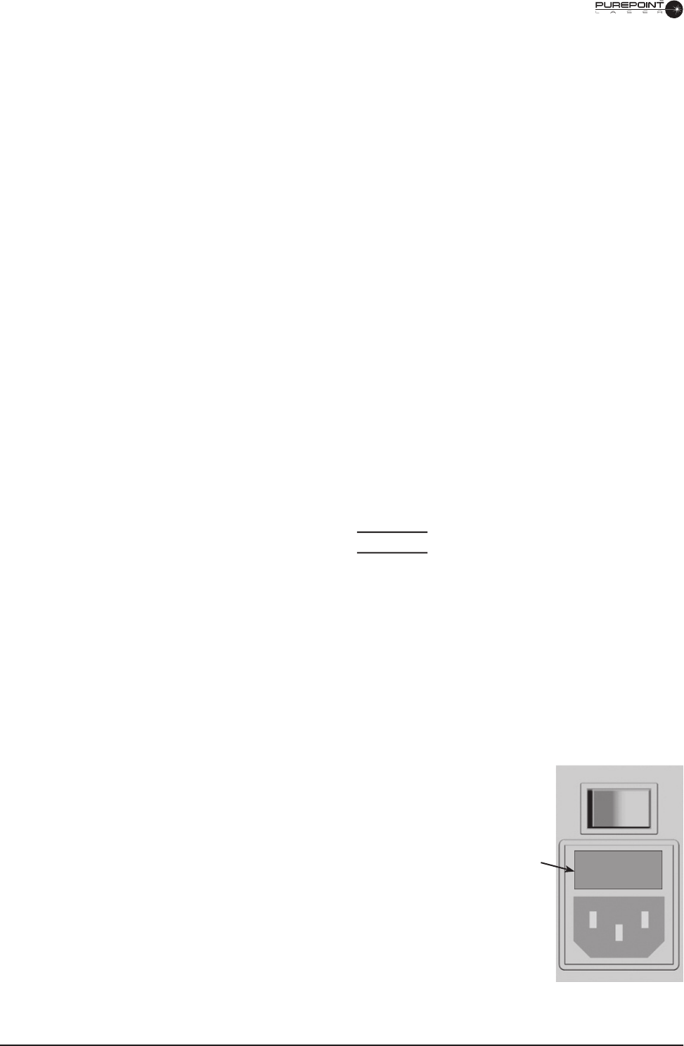
FUSE REPLACEMENT PROCEDURE
NOTE: Use only the recommended fuses for the
PurePoint ™
Laser as listed on
PurePoint ™ Laser as listed on PurePoint ™
the fuse label.
1 Turn system power off and disconnect power cord
from the PurePoint ™ Laser before changing fuses.
2 Remove the fuse clip from the fuse holder using a
small screwdriver.
3 Inspect fuses in holder for damage or a burnt
connection.
4 Place new fuses in each side of holder in fuse clip
(replace with fuses rated T5A/250V or contact your
local Alcon representative).
5 Replace fuse clip into the fuse holder. Close fuse
holder.
Fuse

8065751131 4.3
CALIBRATION VERIFICATION
Calibration verifi cation must be performed at least every twelve months to verify that
the laser output is within tolerance and calibration is not required. It is recommended
to call Alcon Technical Services before conducting the calibration verifi cation
procedure.
CAUTION
Serious damage to the instrument may occur if these procedures are not
performed by qualifi ed personnel.
SPECIAL TOOLS
Computer, with browser software; MS Internet Explorer or equivalent
Custom service ethernet cable (Alcon p/n 023-100)
Power Meter, Thermopile type (Coherent FieldMaster w/ LM-10 head or
equivalent)
Laser Safety Goggles (OD4 or above, at 532 nm wavelength)
Optics cleaning kit, including spectroscopic grade methanol, lens paper and
air blower
Light Meter (Labsphere HLMS 200P or equivalent) - A power meter may be
used instead, using the following conversion factors:
• Ophir Nova with PD300-SH head
(use conversion factor 2.5mW=1 Lumen; divide meter reading by 2.5)
• Newport 840-C with 818SL
(use conversion factor 1.9mW=1 Lumen; divide meter reading by 1.9)
• Coherent Field Master w/LM-10 head
(use conversion factor 2.9mW=1 Lumen; divide meter reading by 2.9)
WARNING!
Laser light emitted from the fi ber and laser head is powerful enough to cause
serious eye or skin damage. Maintenance should be performed only by properly
trained personnel, following established guidelines for laser safety. The use of
protective eye wear is mandatory.
•
•
•
•
•
•
4.4
8065751131
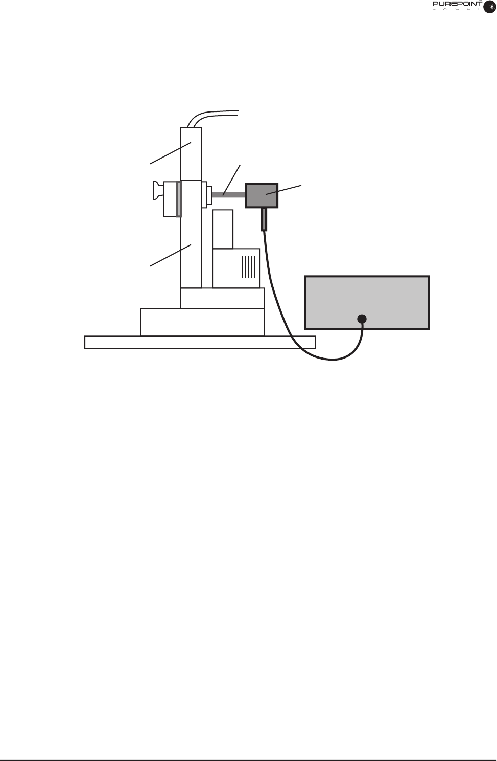
1 Exposure Time Verifi cation
1.1 Setup the system as shown in Figure 4-1. (Where slit lamp is not used, connect a
test fi ber or endoprobe and direct the distal output into the photo cell.)
Figure 4-1 Exposure Time Test Confi guration (shown for slit lamp)
1.2 Set spot size to 250 microns on the zoom. Adjust the distance between the slit
lamp and photo cell to obtain a beam size of 2mm or more on the photo cell.
Use aiming beam to determine spot size on the photo cell.
1.3 Set the exposure time to 0.1s and treatment beam power to minimum then select
READY mode.
1.4 Fire the laser and record the exposure time as determined from the oscilloscope.
1.5 Repeat steps 1.3 and 1.4 for each time value listed in Table 4-1.
Oscilloscope
Photo Cell
Laser Beam
Slit lamp
adaptation
Slit lamp
8065751131 4.5
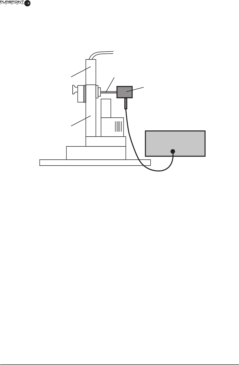
2 Slit Lamp Power Verifi cation
2.1 Setup the system as shown in Figure 4-2.
Figure 4-2 Power Test Confi guration (shown for Slit Lamp)
2.2 Set the exposure time to CW.
2.3 Set spot size to 250 microns on the zoom. Adjust the distance between the slit
lamp and wattmeter cell to obtain a beam size of 2mm or more on the wattmeter
cell. Use aiming beam to determine spot size on the wattmeter cell.
2.4 Set the treatment power to 0.10 W then press the Standby/Ready key.
2.5 Fire the laser and record the wattmeter power reading into Table 4-1.
2.6 Repeat steps 2.4 and 2.5 for each value listed in the Slit Lamp section of Table
4-1.
3 Endoprobe Power Verifi cation
3.1 Setup the system in a similar confi guration as shown in Figure 4-2, to direct the
endoprobe distal output beam into the wattmeter cell.
3.2 Set the exposure time to CW.
3.3 Set the treatment power to 0.10 W then press the Standby/Ready key.
3.4 Fire the laser and record the power reading as determined from the Wattmeter.
3.5 Repeat steps 3.3 and 3.4 for each value listed in the Endoprobe section of Table
4-1.
Wattmeter
Wattmeter Cell
Laser Beam
Slit lamp
adaptation
Slit lamp

4.6
8065751131
4 LIO Power Verifi cation
4.1 Setup the system in a similar confi guration as shown in Figure 4-2, to direct the
LIO distal output beam into the wattmeter cell.
4.2 Set the exposure time to CW.
4.3 Set the treatment power to 0.10 W then press the Standby/Ready key.
4.4 Fire the laser and record the power reading as determined from the Wattmeter.
4.5 Repeat steps 4.3 and 4.4 for each value listed in the LIO section of Table 4-1.
5 Energy Matrix Completion
5.1 Complete the matrix by multiplying actual power by actual exposure time and
recording the result, as shown in the example below.
x
5.2 Ensure that all calculated results are within the values listed in each matrix cell.
The listed values are ±15% of the set energy.
• If all calculated energy values are within the specifi ed limits, the system
calibration is OK.
• If any of the calculated energy results are not within the specifi ed limits,
the Terminal Effi ciencies will need to be adjusted. Perform the Setting the
Terminal Effi ciencies procedure following Table 4-1 or
call Alcon Technical
Services
.

8065751131 4.7
Table 4-1 Energy Matrix

4.8
8065751131
6 Setting the Terminal Effi ciencies
If unable to sucessfully complete the Energy Matrix table, use the following
procedure to adjust the Terminal Effi ciencies, and retest.
6.1 With the unit off, connect the service ethernet cable between the console
and service computer. and turn unit ON. Turn the computer ON and start the
browser program.
6.2 Type the IP address into the address box: 161.61.112.69, and hit return. When
the page loads, enter the password: ngl1
6.3 For slit lamp, endoprobe, and/or LIO, use a power test confi guration similar to
as shown in Figure 4-1, to direct the distal output beam into the wattmeter cell.
6.5 Set power to 0.50 watts on the console, exposure time to CW, and select
READY mode.
6.6 Fire the laser and record the power reading as determined from the wattmeter.
6.7 Calculate the new Terminal Effi ciency cooeffi cient using the following formula:
new coeffi cient = (old coeffi cient) X (measured power in Step 6.6)
0.5
6.8 Enter the new value in the Terminal Effi ciency window for the respective
device, and click the SAVE button.
6.9 Repeat as needed to bring all values within compliance to complete the Energy
Matrix Table 4-1, for each delivery device. If unable to sucessfully complete
the matrix, the unit will need a System Calibration, as outlined in the following
procedure.

8065751131 4.9
SYSTEM CALIBRATION
WARNING!
Laser light emitted from the fi ber and laser head is powerful enough to cause
serious eye or skin damage. Maintenance should be performed only by properly
trained personnel, following established guidelines for laser safety. The use of
protective eye wear is mandatory.
1 With the unit off, connect the service ethernet cable between the console
and service computer. and turn unit ON. Turn the computer ON and start the
browser program.
2 Type the IP address into the address box: 161.61.112.69, and hit return. When
the page loads, enter the password: ngl1
3 Enter and save the following values:
3.1 10 ºC for Minimum Diode Temperature value.
3.2 50 ºC for Maximum Diode Temperature value.
3.3 5 ºC for Minimum LBO Temperature value.
3.4 60 ºC for Maximum LBO Temperature value.
4 Enter and save the following values as denoted on the laser engine:
4.1 Diode Temperature
4.2. LBO Temperature
4.3 Maximum Current
5 Wait at least 2 minutes for the engine to come to proper working temperature for
the calibration. Select Port 1 on the console.
6 On the computer, set Simmer Value to 11 amps. Be aware the laser engine is
now lasing and producing visible output.
7 LBO Temperature Optimization -
1.7.1 On the computer, vary the LBO Temperature Setpoint to maximize the
Pmon1 reading. Use the browser refresh button after each change, and allow
5 seconds for adjustment before reading the new Pmon value. Begin with the
default value noted in Step 1.4.2, and sequentially change in +/- 1, 0.5, and 0.25
-degree steps, to fi ne-tune the setpoint for maximum Pmon reading.
8 On the computer, set the Simmer Value to 5 amps.
9 Select Output Calibration on the computer

4.10
8065751131
10 Pmon 1 Low-Power Calibration -
10.1 Select Port 1 on the console.
10.2 Press “Start Pmon Calibration” on computer.
10.3 Set laser in CONTINUOUS mode on the console.
10.4 Set POWER to 100mw on the console.
10.5 Select READY mode on the console.
10.6 Fire the laser and measure output power directly from Port 1.
10.7 Press “Start Calibration” on the computer
10.8 Input 100mW into the Low Power Display fi eld.
10.9 Input the power, as previously measured, into the Actual Power Field,
and press Save
10.10 Return to STANDBY mode on the console.
10.11 Repeat the Pmon 1 Low-Power Calibration as needed (2 or 3 times) to
bring Displayed/Actual tracking as close as possible.
11 Pmon 1 High-Power Calibration
11.1 Press “Start Pmon Calibration” on computer
11.2 Set laser in CONTINUOUS mode on the console.
11.3 Set POWER to 1 Watt on the console.
11.4 Select READY mode on the console.
11.5 Fire the laser and measure the actual output power directly from Port
1.
11.6 Press “Start Calibration” on the computer
11.7 Input 1 Watt into the Low Power Display fi eld.
11.8 Input the power, as previously measured, into the Actual Power Field,
and press Save
11.9 Return to STANDBY mode on the console.
11.10 Repeat the Pmon 1 High-Power Calibration as needed (2 or 3
times) to bring Displayed/Actual tracking as close as possible.
12 Repeat steps 1.10 and 1.11 for Low/High Power Calibration for Pmon 2.
13 Repeat the Delivered Power Calibration, adjusting the Terminal Effi ciencies as
required, so to sucessfully complete the Energy Matrix for each delivery device.

8065751131 4.11
AIMING BEAM / LIO ILLUMINATION CALIBRATION
1 With the unit off, connect the service ethernet cable between the console
and service computer. and turn unit ON. Turn the computer ON and start the
browser program.
2 Type the IP address into the address box: 161.61.112.69, and hit return. When
the page loads, enter the password: ngl1
3 Aiming Beam Calibration -
3.1 Adjust aiming beam power output for Port 1 to 0.9 - 0.99mW.
3.2 Click “Set Max Value” on the computer.
3.3 Repeat for Port 2.
4. LIO Illumination Calibration -
4.1 Adjust light output to 90 foot-candle.
4.2 Click “Set Max Value”

4.12
8065751131
LAST PAGE OF THIS SECTION
8065751131LAST PAGE OF THIS SECTION 8065751131
THIS PAGE INTENTIONALLY BLANK