Arcadyan Technology WG4005F BARRICADETM 54Mbps g WIRELESS BROADBAND ROUTER User Manual 00
Arcadyan Technology Corporation BARRICADETM 54Mbps g WIRELESS BROADBAND ROUTER 00
Contents
users manual 6

R
OUTING
4-71
When a router receives a routing update that includes changes to an entry,
it updates its routing table to reflect the new route. RIP routers maintain
only the best route to a destination. After updating its routing table, the
router immediately begins transmitting routing updates to inform other
network routers of the change.
Click Save Settings to proceed, or Cancel to change your settings.
Version Sets the RIP (Routing Information Protocol) version to use on
this interface.
Poison Reverse A method for preventing loops that would cause endless
retransmission of data traffic.
Authentication
Required None: No authentication.
Password: A password authentication key is included in the
packet. If this does not match what is expected, the packet will
be discarded. This method provides very little security as it is
possible to learn the authentication key by watching RIP
packets.
Authentication
Code Password Authentication key.
Parameter Description

C
ONFIGURING
THE
B
ARRICADE
4-72
Routing Table
Click Routing Table to view the screen below.
Parameter Description
Flags Indicates the route status:
C = Direct connection on the same subnet.
S = Static route.
R = RIP (Routing Information Protocol) assigned route.
I = ICMP (Internet Control Message Protocol) Redirect route.
Network Address Destination IP address.
Netmask The subnetwork associated with the destination.
This is a template that identifies the address bits in the
destination address used for routing to specific subnets. Each
bit that corresponds to a “1” is part of the subnet mask
number; each bit that corresponds to “0” is part of the host
number.
Gateway The IP address of the router at the next hop to which frames
are forwarded.
Interface The local interface through which the next hop of this route is
reached.
Metric When a router receives a routing update that contains a new or
changed destination network entry, the router adds 1 to the
metric value indicated in the update and enters the network in
the routing table.

A-1
A
PPENDIX
A
T
ROUBLESHOOTING
This section describes common problems you may encounter and possible
solutions to them. The Barricade can be easily monitored through panel
indicators to identify problems.
Troubleshooting Chart
Symptom Action
LED Indicators
Power LED is
off
• Check connections between the Barricade, the
external power supply, and the wall outlet.
• If the power indicator does not turn on when the
power cord is plugged in, you may have a problem
with the power outlet, power cord, or external power
supply. However, if the unit powers off after running
for a while, check for loose power connections, power
losses, or surges at the power outlet. If you still cannot
isolate the problem, then the external power supply
may be defective. In this case, contact Technical
Support for assistance.

T
ROUBLESHOOTING
A-2
LED Indicators
LAN LED is
Off
• Verify that the Barricade and attached device are
powered on.
• Be sure the cable is plugged into both the Barricade
and the corresponding device.
• Verify that the proper cable type is used and that its
length does not exceed the specified limits.
• Be sure that the network interface on the attached
device is configured for the proper communication
speed and duplex mode.
• Check the adapter on the attached device and cable
connections for possible defects. Replace any
defective adapter or cable if necessary.
Network Connection Problems
Cannot ping the
Barricade from
the attached
LAN, or the
Barricade cannot
ping any device
on the attached
LAN
• Verify that the IP addresses are properly configured.
For most applications, you should use the Barricade’s
DHCP function to dynamically assign IP addresses to
hosts on the attached LAN. However, if you manually
configure IP addresses on the LAN, verify that the
same network address (network component of the IP
address) and subnet mask are used for both the
Barricade and any attached LAN devices.
• Be sure the device you want to ping (or from which
you are pinging) has been configured for TCP/IP.
Troubleshooting Chart
Symptom Action

T
ROUBLESHOOTING
A-3
Management Problems
Cannot connect
using the web
browser
• Be sure to have configured the Barricade with a valid
IP address, subnet mask, and default gateway.
• Check that you have a valid network connection to the
Barricade and that the port you are using has not been
disabled.
• Check the network cabling between the management
station and the Barricade.
Forgot or lost
the password
•Press the Reset button on the rear panel (holding it
down for at least six seconds) to restore the factory
defaults.
Troubleshooting Chart
Symptom Action

T
ROUBLESHOOTING
A-4
Wireless Problems
A wireless PC
cannot associate
with the
Barricade.
• Make sure the wireless PC has the same SSID settings
as the Barricade.
See “Channel and SSID” on page 4-24.
• You need to have the same security settings on the
clients and the Barricade. See “Security” on page 4-27.
The wireless
network is often
interrupted.
• Move your wireless PC closer to the Barricade to find
a better signal. If the signal is still weak, change the
angle of the antenna.
• There may be interference, possibly caused by
microwave ovens or wireless phones. Change the
location of the possible sources of interference or
change the location of the Barricade.
• Change the wireless channel on the Barricade. See
“Channel and SSID” on page 4-24.
• Check that the antenna, connectors, and cabling are
firmly connected.
The Barricade
cannot be
detected by a
wireless client.
• The distance between the Barricade and wireless PC is
too great.
• Make sure the wireless PC has the same SSID and
security settings as the Barricade. See “Channel and
SSID” on page 4-24 and “Security” on page 4-27.
Troubleshooting Chart
Symptom Action
B-1
A
PPENDIX
B
C
ABLES
Ethernet Cable
Caution:
Do not plug a phone jack connector into an RJ-45 port.
For
Ethernet connections, use only twisted-pair cables with RJ-45
connectors that conform to FCC standards.
Specifications
Wiring Conventions
For Ethernet connections, a twisted-pair cable must have two pairs of
wires. Each wire pair is identified by two different colors. For example, one
wire might be red and the other, red with white stripes. Also, an RJ-45
connector must be attached to both ends of the cable.
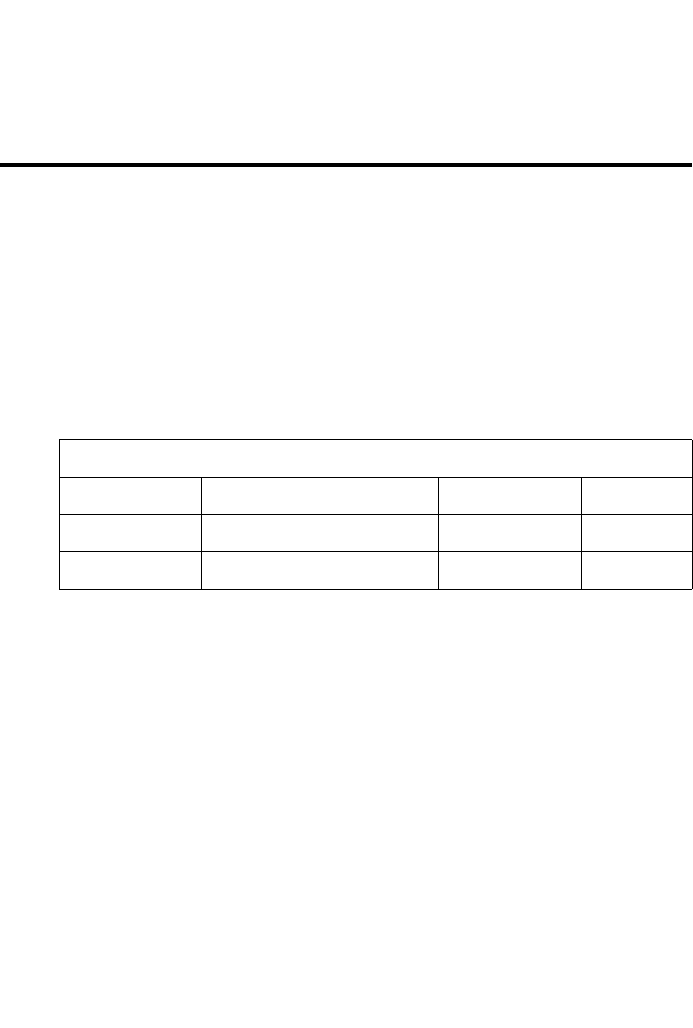
Cable Types and Specifications
Cable Type Max. Length Connector
10BASE-T Cat. 3, 4, 5 100-ohm UTP 100 m (328 ft) RJ-45
100BASE-TX Cat. 5 100-ohm UTP 100 m (328 ft) RJ-45
C
ABLES
B-2
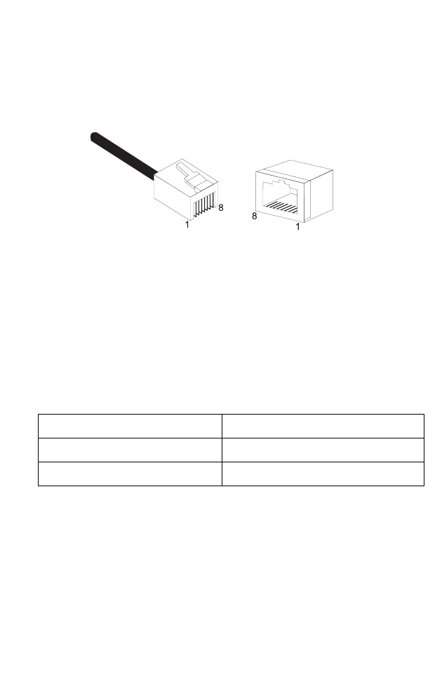
Each wire pair must be attached to the RJ-45 connectors in a specific
orientation. The following figure illustrates how the pins on an Ethernet
RJ-45 connector are numbered. Be sure to hold the connectors in the same
orientation when attaching the wires to the pins.
Figure B-1. RJ-45 Ethernet Connector Pin Numbers
RJ-45 Port Ethernet Connection
Use the straight-through CAT -5 Ethernet cable provided in the package
to connect the Barricade to your PC. When connecting to other network
devices such as an Ethernet switch, use the cable type shown in the
following table.
Attached Device Port Type Connecting Cable Type
MDI-X Straight-through
MDI Crossover

RJ-45 P
ORT
E
THERNET
C
ONNECTION
B-3
Pin Assignments
With 10BASE-T/100BASE-TX cable, pins 1 and 2 are used for
transmitting data, and pins 3 and 6 for receiving data.
Straight-Through Wiring
If the port on the attached device has internal crossover wiring (MDI-X),
then use straight-through cable.
RJ-45 Pin Assignments
Pin Number Assignment*
1Tx+
2Tx-
3Rx+
6Rx-
* The “+” and “-” signs represent the polarity of the
wires that make up each wire pair.
Straight-Through Cable Pin Assignments
End 1 End 2
1 (Tx+) 1 (Tx+)
2 (Tx-) 2 (Tx-)
3 (Rx+) 3 (Rx+)
6 (Rx-) 6 (Rx-)

C
ABLES
B-4
Crossover Wiring
If the port on the attached device has straight-through wiring (MDI), use
crossover cable.
Crossover Cable Pin Assignments
End 1 End 2
1 (Tx+) 3 (Rx+)
2 (Tx-) 6 (Rx-)
3 (Rx+) 1 (Tx+)
6 (Rx-) 2 (Tx-)

C-1
A
PPENDIX
C
S
PECIFICATIONS
IEEE Standards
IEEE 802.3 10 BASE-T Ethernet
IEEE 802.3u 100 BASE-TX Fast Ethernet
IEEE 802.3, 802.3u, 802.11g, 802.1D
ITU G.dmt
ITU G.Handshake
ITU T.413 issue 2 - ADSL full rate
LAN Interface
4 RJ-45 10 BASE-T/100 BASE-TX ports
Auto-negotiates the connection speed to 10 Mbps Ethernet or 100 Mbps
Fast Ethernet, and the transmission mode to half-duplex or full-duplex
WAN Interface
1 ADSL RJ-45 port
Indicator Panel
LAN 1~4, WLAN, PPPoE/DSL, WAN, Power
Dimensions
145 x 95 x 36 mm (5.70 x 3.74 x 1.41 in)
Weight
0.175 kg (0.469 lbs)
Input Power
9 V 1 A
Power Consumption
9 Watts maximum

S
PECIFICATIONS
C-2
Advanced Features
Dynamic IP Address Configuration – DHCP, DNS, DDNS
Firewall – Client privileges, hacker prevention and logging,
Stateful Packet Inspection
Virtual Private Network – PPTP, IPSec pass-through, VPN pass-through,
VLAN Ping
Internet Standards
RFC 826 ARP, RFC 791 IP, RFC 792 ICMP, RFC 768 UDP, RFC 793 TCP,
RFC 783 TFTP, RFC 1483 AAL5 Encapsulation, RFC 1661 PPP,
RFC 1866 HTML, RFC 2068 HTTP, RFC 2364 PPP over ATM
Radio Features
Wireless RF module Frequency Band
802.11g Radio: 2.4GHz
802.11b Radio: 2.4GHz
USA - FCC
2412~2462MHz (Ch1~Ch11)
Canada - IC
2412~2462MHz (Ch1~Ch11)
Europe - ETSI
2412~2472MHz (Ch1~Ch13)
Japan - STD-T66/STD-33
2412~2484MHz (Ch1~Ch14)
Modulation Type
OFDM, CCK
Operating Channels IEEE 802.11b Compliant:
11 channels (US, Canada)
13 channels (ETSI)
14 channels (Japan)
Operating Channels IEEE 802.11g Compliant:
13 channels (US, Canada, Europe, Japan)

S
PECIFICATIONS
C-3
RF Output Power Modulation Rate-Output Power (dBm)
802.11b - 1Mbps 16
802.11b - 2Mbps 16
802.11b - 5.5Mbps 16
802.11b - 11Mbps 16
Modulation Rate-Output Power (dBm)
802.11g - 6Mbps 15
802.11g - 9Mbps 15
802.11g - 12Mbps 15
802.11g - 18Mbps 15
802.11g- 24Mbps 15
802.11g - 36Mbps 15
802.11g- 48Mbps 15
802.11g - 54Mbps 15
Sensitivity Modulation Rate-Receiver 2.412 ~ 2.484 HGz Sensitivity
(dBm)
802.11b - 1Mbps -90
802.11b - 2Mbps -88
802.11b - 5.5Mbps -85
802.11b- 11Mbps -84
Modulation Rate-Receiver Sensitivity Typical (dBm)
802.11g - 6Mbps -88
802.11g - 9Mbps -87
802.11g - 12Mbps -84
802.11g - 18Mbps -82
802.11g - 24Mbps -79
802.11g - 36Mbps -75
802.11g - 48Mbps -68
802.11g - 54Mbps -68

S
PECIFICATIONS
C-4
Standards Compliance
Safety
TÜV
Environmental
CE Mark
Temperature
Operating 0 to 40 °C (32 to 104 °F)
Storage -40 to 70 °C (-40 to 158 °F)
Humidity
5% to 95% (non-condensing)
Vibration
IEC 68-2-36, IEC 68-2-6
Shock
IEC 68-2-29
Drop
IEC 68-2-32