Avery Dennison Retail Information Services 9460IPLA3021 Wireless Printer User Manual 9460SMCV
Avery Dennison Retail Information Services, LLC Wireless Printer 9460SMCV
Contents
- 1. Manual
- 2. Service manual
- 3. Symbol manual
- 4. Radio confiuration
Service manual
TC9460SM Rev AB 05/00 ©2000 Monarch Marking Systems, Inc. All rights reserved.
Monarch
9460 Printer

Each product and program carries a respective written warranty, the only warranty on
which the customer can rely. Monarch reserves the right to make changes in the
product, the programs, and their availability at any time and without notice. Although
Monarch has made every effort to provide complete and accurate information in this
manual, Monarch shall not be liable for any omissions or inaccuracies. Any update
will be incorporated in a later edition of this manual.
©2000 Monarch Marking Systems, Inc. All rights reserved. No part of this publication
may be reproduced, transmitted, stored in a retrieval system, or translated into any
language in any form by any means, without the prior written permission of Monarch
Marking Systems, Inc.
WARNING
This equipment has been tested and found to comply with the limits for a Class A digital device,
pursuant to Part 15 of the FCC Rules. These limits are designed to provide reasonable protection
against harmful interference when the equipment is operated in a commercial environment. This
equipment generates, uses, and can radiate radio frequency energy and, if not installed and used in
accordance with the instruction manual, may cause harmful interference to radio communications.
Operation of this equipment in a residential area is likely to cause harmful interference in which case
the user will be required to correct the interference at his own expense.
CANADIAN D.O.C. WARNING
This digital apparatus does not exceed the Class A limits for radio noise emissions from digital
apparatus set out in the Radio Interference Regulations of the Canadian Department of
Communications.
Le présent appareil numérique n’émet pas de bruits radioélectriques dépassant les limites
applicables aux appareils numériques de la classe A prescrites dans le Réglement sur le brouillage
radioélectrique édicte par le ministère des Communications du Canada.
Trademarks
Monarch is a registered trademark of Monarch Marking Systems, Inc.
Monarch, 917, 9403, 9800, 9805, 9820, 9830, 9835, 9840, and 9856 are trademarks of Monarch Marking Systems,
Inc.
Paxar is a trademark of Paxar Corporation.
Microsoft and MS-DOS are registered trademarks of Microsoft in the U.S. and other countries.
Windows is a registered trademark of Microsoft in the U.S. and other countries.
TrueType is a trademark of Apple Computer, Inc.
Hewlett-Packard is a registered trademark of Hewlett-Packard Company.
CG Triumvirate and CG Triumvirate Bold are trademarks of AGFA Corporation.
Adobe and Acrobat are trademarks of Adobe Systems Incorporated which may be registered in certain jurisdictions.
Centronics is a registered trademark of Centronics Data Computer Corporation.
Monarch Marking Systems
P.O. Box 608
Dayton, Ohio 45401

Confidential
January 2001 Page i
SAFETY SUMMARY
Warning and caution messages appear throughout this manual. They alert you to potential safety hazards or
potential damage to equipment. The messages and their meanings are shown below.
WARNING
Calls attention to improper practices that could
result in a potentially serious, even lethal injury.
CAUTION
Calls attention to practices that could cause minor
injury or damage to equipment.
Familiarize yourself with proper procedures before operating or repairing the equipment. Follow these precautions for
your own safety and to protect the equipment.
Equipment Safety
Your body is a giant capacitor. It can store several
thousand volts of electricity. Digital equipment is easily
damaged or destroyed by this static electricity. You do
not have to see a spark to ruin an IC; 50 volts is
enough. To protect the equipment from static damage,
follow these guidelines:
Ground yourself before reaching into the equipment or
touching any circuit board or other electrical
component. The Monarch Static Ground Kit contains
everything you need.
Re-ground yourself whenever you walk away and return
to the equipment. Be especially careful around carpet.
Carpet is a major source of static buildup in the body.
Even a few steps can recharge you.
The smaller the object, the greater the precautions
must be. A board in the machine is better protected
than one that is not plugged in. A chip on a board is
better protected than one in your hand.
Avoid touching pins coming out of a chip or the
connector edge of circuit boards. These metal parts
have signal and data lines that are connected directly to
fragile circuits.

9460 Service Manual Confidential Preface
Page ii January 2001
Table of Contents
Safety Summary i
Chapter 1. Printer Overview & Installation 1
PURPOSE --------------------------------------------------------------------------------------------------------------------------------------------- 1
ELECTROSTATIC DISCHARGE --------------------------------------------------------------------------------------------------------------- 1
PUBLICATIONS -------------------------------------------------------------------------------------------------------------------------------------- 1
EQUIPMENT DESCRIPTION-------------------------------------------------------------------------------------------------------------------- 1
EQUIPMENT SPECIFICATIONS--------------------------------------------------------------------------------------------------------------- 2
Bar Codes------------------------------------------------------------------------------------------------------------------------------------------- 2
Additional Specifications ---------------------------------------------------------------------------------------------------------------------- 2
INSTALLATION AND CHECKOUT PROCEDURES------------------------------------------------------------------------------------- 3
Printer Checkout---------------------------------------------------------------------------------------------------------------------------------- 3
Communications Interface-------------------------------------------------------------------------------------------------------------------- 3
Chapter 2. Physical/Functional Description 5
FRONT CASE ASSEMBLY 11998901/03-------------------------------------------------------------------------------------------------- 6
Platen Roller Assembly------------------------------------------------------------------------------------------------------------------------ 6
Supply Holder Assembly 119991----------------------------------------------------------------------------------------------------------- 7
Latch Springs-------------------------------------------------------------------------------------------------------------------------------------- 7
Peel Roller Assembly--------------------------------------------------------------------------------------------------------------------------- 7
Front Flex Assembly 119995---------------------------------------------------------------------------------------------------------------- 8
RF PCB Assembly 118752------------------------------------------------------------------------------------------------------------------- 8
BATTERY PACK 120095------------------------------------------------------------------------------------------------------------------------- 8
PRINT MODULE ASSEMBLY 11997501/02----------------------------------------------------------------------------------------------- 9
Sensor Flex Assembly 119988 ------------------------------------------------------------------------------------------------------------- 9
Printhead Assembly 119990----------------------------------------------------------------------------------------------------------------- 9
Stepper Motor 119980-------------------------------------------------------------------------------------------------------------------------- 9
IrDA Processor Assembly -------------------------------------------------------------------------------------------------------------------- 9
BACK INNER CASE ASSEMBLY 119961S----------------------------------------------------------------------------------------------- 9
MAIN PCB ASSEMBLY 119810--------------------------------------------------------------------------------------------------------------10
KEYBOARD/DISPLAY ASSEMBLY --------------------------------------------------------------------------------------------------------10
BACK OUTER CASE ASSEMBLY 119960S---------------------------------------------------------------------------------------------10
Chapter 3. Troubleshooting 11
GENERAL PRINT QUALITY COMPLAINTS ----------------------------------------------------------------------------------------------11
PRINTS LIGHT IMAGE ACROSS ENTIRE SUPPLY ----------------------------------------------------------------------------------11
PRINTS LIGHT IMAGE ON ONE SIDE OF SUPPLY ONLY------------------------------------------------------------------------11
PRINTS VOIDS ACROSS PRINT AREA---------------------------------------------------------------------------------------------------11
PRINT IMAGE MISSING DOTS, CREATING A WHITE LINE THROUGH IMAGE AREA --------------------------------12
PRINTS COMPRESSED IMAGE-------------------------------------------------------------------------------------------------------------12
PRINTER DOES NOT FEED-------------------------------------------------------------------------------------------------------------------12
PRINTER SKIPS LABELS ----------------------------------------------------------------------------------------------------------------------12
NO DISPLAY AT POWER UP-----------------------------------------------------------------------------------------------------------------12
INCORRECT OR NO RESPONSE WHEN KEY IS PRESSED--------------------------------------------------------------------12
NO COMMUNICATIONS BETWEEN PRINTER AND HOST------------------------------------------------------------------------12
BATTERY CONDITION CHECK ---------------------------------------------------------------------------------------------------------------13
PRINTER SHUTS COMPLETELY OFF WHILE PRINTING--------------------------------------------------------------------------13

Preface Confidential 9460 Service Manual
January 2001 Page iii
Chapter 4. Diagnostics 14
OVERVIEW-------------------------------------------------------------------------------------------------------------------------------------------14
POWER-UP DIAGNOSTICS--------------------------------------------------------------------------------------------------------------------14
RAM Test ------------------------------------------------------------------------------------------------------------------------------------------14
Printhead Test------------------------------------------------------------------------------------------------------------------------------------14
Battery Check------------------------------------------------------------------------------------------------------------------------------------14
USER DIAGNOSTICS-----------------------------------------------------------------------------------------------------------------------------14
Password Entry----------------------------------------------------------------------------------------------------------------------------------15
Diagnostics----------------------------------------------------------------------------------------------------------------------------------------15
Online Diagnostics------------------------------------------------------------------------------------------------------------------------------16
Setup ------------------------------------------------------------------------------------------------------------------------------------------------16
Service Diagnostics ----------------------------------------------------------------------------------------------------------------------------17
Exit---------------------------------------------------------------------------------------------------------------------------------------------------17
MONARCH INITIALIZATION FILES (.MIF)-------------------------------------------------------------------------------------------------18
PC DIAGNOSTICS ---------------------------------------------------------------------------------------------------------------------------------19
IMMEDIATE COMMANDS ----------------------------------------------------------------------------------------------------------------------19
Chapter 5. Tests and Adjustments 20
MAIN PCB ASSEMBLY--------------------------------------------------------------------------------------------------------------------------20
BATTERY TEST-------------------------------------------------------------------------------------------------------------------------------------20
SENSOR CALIBRATION-------------------------------------------------------------------------------------------------------------------------20
PRINTHEAD VERIFICATION-------------------------------------------------------------------------------------------------------------------20
Chapter 6. Disassembly Procedures 21
TOOLS REQUIRED--------------------------------------------------------------------------------------------------------------------------------21
REMOVING THE BOOT, 11997203/06/08-------------------------------------------------------------------------------------------------21
REMOVING THE BACK OUTER CASE, 119960S-------------------------------------------------------------------------------------21
Assembly Note-----------------------------------------------------------------------------------------------------------------------------------21
REMOVING THE DB9 DOOR------------------------------------------------------------------------------------------------------------------21
REMOVING THE CASE TOP------------------------------------------------------------------------------------------------------------------21
REMOVING THE KEYBOARD/DISPLAY ASSEMBLY-------------------------------------------------------------------------------21
REMOVING THE CPU BOARD ASSEMBLY --------------------------------------------------------------------------------------------22
REMOVING THE PRINT MODULE-----------------------------------------------------------------------------------------------------------22
REMOVING THE FRONT CASE ASSEMBLY-------------------------------------------------------------------------------------------22
Assembly Note-----------------------------------------------------------------------------------------------------------------------------------22
RETROFITTING TO IrDA -------------------------------------------------------------------------------------------------------------------------22
Chapter 7. PC Diagnostics 23
ENABLING ONLINE DIAGNOSTICS---------------------------------------------------------------------------------------------------------23
DETECTING THE PRINTER--------------------------------------------------------------------------------------------------------------------24
DOWNLOADING FILES TO THE PRINTER-----------------------------------------------------------------------------------------------24
DISPLAYING MUX VALUES-------------------------------------------------------------------------------------------------------------------25
TESTING THE PRINTHEAD--------------------------------------------------------------------------------------------------------------------25
DISPLAYING SERVICE TOTALS-------------------------------------------------------------------------------------------------------------25
DISPLAYING STOCK HISTORY --------------------------------------------------------------------------------------------------------------26
UPLOADING IMAGES----------------------------------------------------------------------------------------------------------------------------26
Appendix A. Error Codes 28
Appendix B. Care & Maintainence 34
CLEANING--------------------------------------------------------------------------------------------------------------------------------------------34
CLEARING LABEL JAMS-----------------------------------------------------------------------------------------------------------------------35
Appendix C. Circuit Card Assembly Layouts 36

9460 Service Manual Confidential Preface
Page iv January 2001
List of Figures
Figure 1-1. 9460 printer. .......................................................................................................................................2
Figure 1-2. Connecting Communications Cable. .....................................................................................................3
Figure 1-3. RS-232 Serial Port Connector Pinouts. .................................................................................................3
Figure 2-1. Printer Main Assembly........................................................................................................................5
Figure 2-2. Front Case Assembly..........................................................................................................................6
Figure 2-3. Supply Holder Assembly. ....................................................................................................................7
Figure 2-4. Print Module Assembly. ......................................................................................................................8
Figure C-1. Main PCB (Primary Side). .................................................................................................................36
Figure C-2. Main PCB (Secondary Side)..............................................................................................................37
Figure C-3. RF PCB...........................................................................................................................................38
Figure C-4. IrDA Processor Board. ......................................................................................................................38
Figure C-5. IrDA Transceiver. ..............................................................................................................................39
List of Tables
Table 1-1. Related Publications.............................................................................................................................1
Table 1-2. Specifications ......................................................................................................................................2
Table 4-1. 9460 Printer Menu Structure................................................................................................................14

Confidential
January 2001 Page 1
CHAPTER 1. PRINTER OVERVIEW & INSTALLATION
PURPOSE
This manual contains information service technicians
need to service, troubleshoot and repair the Monarch
Sierra Sport2™ 9460™ printer.
• Chapter 1 contains general information and
installation procedures.
• Chapter 2 contains physical and functional
descriptions of major components.
• Chapter 3 contains procedures to perform
troubleshooting beyond the capabilities of built-
in diagnostics.
• Chapter 4 contains procedures to run built-in
diagnostics for initial fault detection.
• Chapter 5 describes printer tests and
adjustments.
• Chapter 6 contains step-by-step procedures to
remove and replace failed assemblies and
modules.
• Chapter 7 describes diagnostics available with
the Monarch MPCL™ Toolbox software.
Additional maintenance assistance is available in
Appendix A, Error Codes; Appendix B, Care &
Maintenance; Appendix C, Circuit Card Assembly
Layouts.
The 9460 Illustrated Parts Breakdown contains
additional information for replacing individual parts.
ELECTROSTATIC
DISCHARGE
The 9460 printer contains devices that are sensitive to
electrostatic discharge (ESD). It is essential that you
follow proper ESD procedures. Use the Monarch-
approved ESD Field Service Kit. Failure to provide
proper static grounding can damage the printer
components.
PUBLICATIONS
Field service technicians should be familiar with the
documentation shown in the following table.
Table 1-1. Related Publications.
Title Publication
Number
Operator’s Handbook TC9460OH
1-Station Battery Charger
Operating Instructions TC9461OI
AC Adapter Instructions TC9463OI
4-Station Battery Charger
Operating Instructions TC9464OI
Installing a Linerless Platen
Roller TC9460ACPROI
Carrying Your 9460 Printer TC9460ACHPOI
Programmer's Manual
(placed on Web site) TC9460PM
RCL Programmer’s Manual
(placed on Web site) TC9460RCL
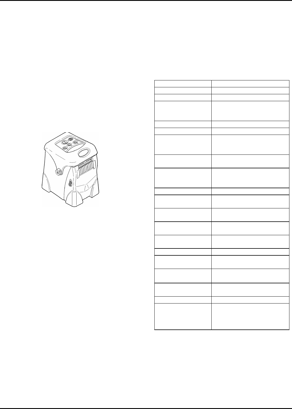
EQUIPMENT DESCRIPTION
The 9460 printer is portable, and can print an image
that is 1.89 inches wide on supplies up to 2.05 inches
wide. Options include RF and IrDA communications,
1- and 4-station battery chargers, on-demand printing,
an AC adapter, linerless printing, shoulder strap, hand
strap, hip strap, and a belt clip that comes individually
or with the hip strap.
The display is graphical. The keyboard has 5 keys-
power, feed, and three that are context-sensitive (They
have different functions according to the selected menu
option.)
The standard memory configuration consists of 1 MB of
Flash and 512K of static Random Access Memory
(RAM).
The printer uses thermal direct printing to print on
supplies listed in Table 1-2.
The printer operates in continuous or optionally, on-
demand modes.
9460 Service Manual Confidential Printer Overview & Installation
Page 2 January 2001
In continuous (non-peel) mode, the entire batch job is
printed and fed in one continuous operation. The
supply and liner (if used) are fed out together. Linerless
models are also available but must use the special
linerless platen roller.
In on-demand (peel) mode, the on-demand sensor
detects the removal of a label, and the printer prints and
feeds the next label. In on-demand mode, the label is
separated (peeled) from the supply liner.
9460 printers have seven major elements:
• Front Case Assembly
• Battery Pack
• Print Module Assembly
• Back Inner Case Assembly
• Main PCB Assembly
• Keyboard/Display Assembly
• Back Outer Case Assembly
Figure 1-1. 9460 printer.
Chapter 2 contains a physical and functional
description of each element.
EQUIPMENT
SPECIFICATIONS
Bar Codes
The printer prints the following bar codes:
Linear Bar Codes
UPCA UPCA+2
UPCE UPCA+5
EAN8 UPCA+Price CD
EAN13 UPCE+2
POSTNET UPCE+5
I 2 of 5 EAN8+2
I 2 of 5 with Barrier Bar EAN8+5
Extended Code 39 EAN13+2
Codabar (NW7) EAN13+5
Code 128 EAN13+Price CD
Code 93 MSI
2-D Stacked Bar Codes
Code 16K PDF 417
Maxicode Data Matrix
Additional Specifications
Specifications for the 9460 printer and its supplies are
shown below.
Table 1-2. Specifications
Feature Specification
Shipping Weight 3.1 lbs. (1.4 kg)
Battery Pack 7.4V Lithium Ion
Chargers 15 VDC at 5 A (1-Station) or
24 VDC at 4.5 A
8 VDC at 5 A (4-Station)
Operating Limits 40°F to 104°F (4°C to 40°C)
Relative Humidity 5% to 90 % Non-condensing
Display Multi-line, graphical LCD with
backlight and adjustable
contrast
Keyboard 5 keys (power, feed, and three
context-sensitive)
Printhead 1.89 inches/48 mm/384 dots
wide; (203 dots per inch; 8
dots per mm)
Printing Method Thermal Direct
Print Speed Up to 3 inches (76 mm) per
second
Maximum Print Area 22.68 square inches (146 sq
cm)
Maximum Print
Image Width
1.89 inches (48 mm)
Maximum Print
Image Length
12 inches (305 mm)
Stock:
Supply Types Tags, labels, and receipt
paper (paper and synthetic).
Width .5" (13 mm) to 2.05" (52
mm)
Length Min. 0.5 inch (13 mm)
Max. 12 inches (305 mm)
Supply Thickness .0024 inches to .007 inches
Roll Diameter Maximum roll OD: 2.5” (64
mm)
Minimum core ID: 1.02” (26
mm)
Printer Overview & Installation Confidential 9460 Service Manual
January 2001 Page 3
INSTALLATION AND
CHECKOUT PROCEDURES
1. Clear a work area approximately two feet wide.
2. Carefully open shipping carton.
3. Remove documentation.
4. Remove large cardboard insert.
5. Remove smaller cardboard insert.
6. Remove battery pack.
7. Place packing materials back in the carton and
store carton.
8. Inspect printer for damage. Report damage using
established procedures.
9. Insert the battery pack into the printer if charging
through the printer charger adapter. Otherwise,
remove the battery pack from the printer and insert
into the battery charger adapter.
10. Charge the battery (approximately 2 hours for full
charge).
Printer Checkout
1. Turn printer on by pressing the power button.
2. Check printer display for error indications.
3. Push down on the locking tabs to install supplies.
4. Print a test label. Use instructions in Chapter 4.
5. Review setup instructions with operator. Refer to
9460 Operator’s Handbook (TC9460OH).
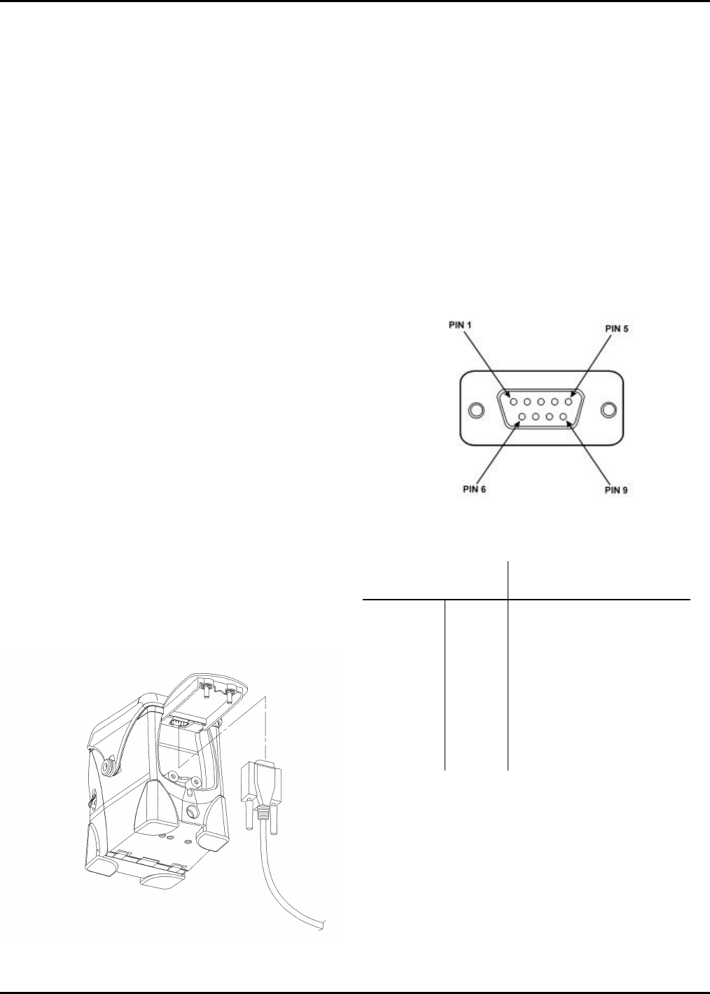
6. Connect communications cable as shown. Ensure
the cable is pushed inward as the door is tightened
down to provide strain relief.
Figure 1-2. Connecting Communications Cable.
Communications Interface
The printer’s asynchronous RS-232 port is a DB9
connector located on the inside of the back outer case.
The following parameters are software selectable. The
defaults are listed in bold.
• Baud rate: 1200, 2400, 4800, 9600, 19200, or
38400, 57600, 115.2K
• Parity: Odd, Even, or None
• Stop Bits: 1 or 2
• Data Bits: 7 or 8-bit
• Flow Control: XON/XOFF, RTS, or DTR
Following are the pinouts and signals of the DB9
connector.
Figure 1-3. RS-232 Serial Port Connector Pinouts.
ANSI/EIA-232-D
Contact # Circuit Description
8 CTS Clear to Send
7 RTS Request to Send
3 TXD Transmitted Data
5 GND Signal Ground
2 RXD Received Data
4 DTR Data Terminal Ready
6 DSR Data Set Ready
1 --- Reserved – Do not connect
9 --- N/C

9460 Service Manual Confidential Printer Overview & Installation
Page 4 January 2001
The following cables are available to connect the 9460
printer to other devices.
Cable Number Type
12029306 Symbol 3800 LRT/LDT
12029309 Telxon 960
12029314 DB9 to DB9 female serial port
12029315 DB9 to DB25 female serial
port
12029316 Symbol PDT 3100
12029323 Unterminated locking
12029343 Telxon 960SL
12029344 Symbol PDT 6100
12029345 Symbol SPT 1500
12029346 Symbol SPT 1700
12029347 Symbol SPT 2700
Confidential
January 2001 Page 5
CHAPTER 2. PHYSICAL/FUNCTIONAL DESCRIPTION
This chapter contains a physical and functional description of the 9460 printer modules shown below.
• Front Case Assembly
• Battery Pack
• Print Module Assembly
• Back Inner Case Assembly
• Main PCB Assembly
• Keyboard/Display Assembly
• Back Outer Case Assembly
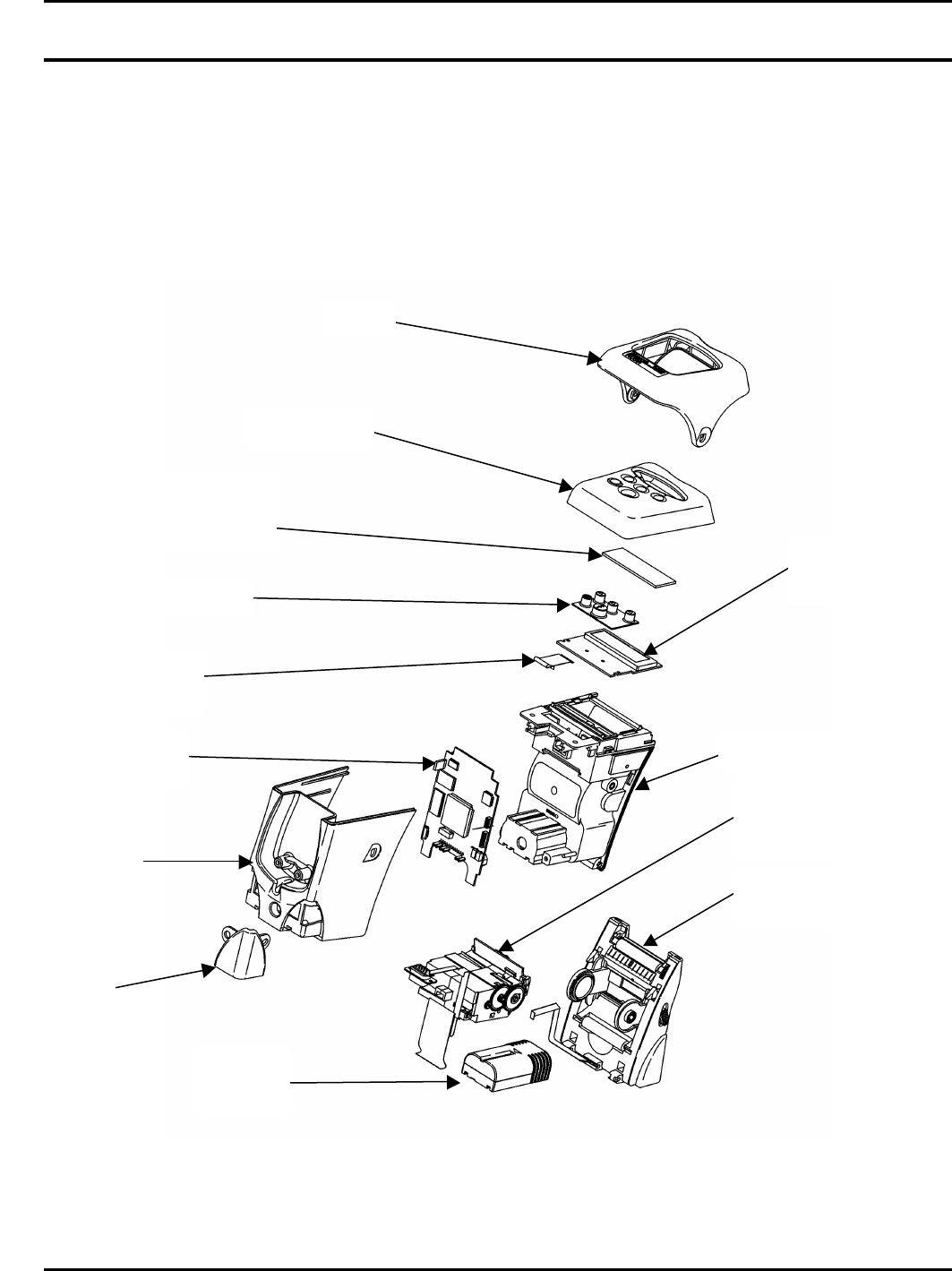
Figure 2-1. Printer Main Assembly.
Boot
Case Top
Display
Lens
Assembly
Keyboard
Display PCB
Assembly
Printer
Contact
Main PCB
Assembly
Back Outer
Case
Back Inner Case
Front Case
Assembly
Print
Module
Assembly
Battery
Pack
Foot
9460 Service Manual Confidential Physical/Functional Description
Page 6 January 2001
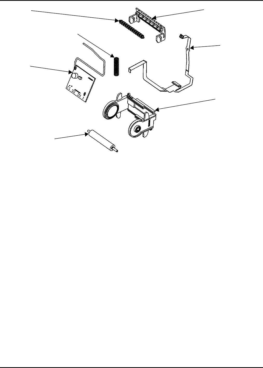
Figure 2-2. Front Case Assembly.
FRONT CASE ASSEMBLY
11998901/03
The Front Case Assembly will be stocked for service
replacement. It contains:
• Platen Roller Assembly
• Supply Holder Assembly
• Latch Springs
• Peel Roller Assembly
• Front Flex Assembly
• RF PCB Assemblies (if ordered as an option-
11998903)
Platen Roller Assembly
The 119951 Platen Roller Assembly provides drive for
feeding the supplies by causing friction against the
backside of the supplies. It is considered an operator-
replaceable item.
A linerless platen roller 119952 is available as an option
and can be easily identified by its burnt orange color.
Peel Door
Compression
Spring
RF PCB
Front Flex
Assembly
Platen Roller
Supply Holder
Assembly
Roller
Confidential
January 2001 Page 7
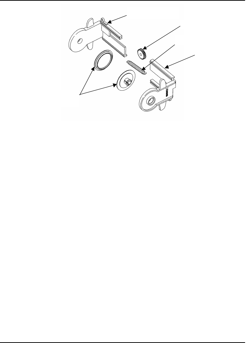
Figure 2-3. Supply Holder Assembly.
Supply Holder Assembly 119991
The Supply Holder Assembly is made up of a molded
part that has a gear rack and provisions for a single
spring on the underside. The design is such that two of
these parts interlock and slide so that any supply roll
width between 12.7 (.50”) and 50.8(2.00”) can be
accommodated. A small pinion gear is mounted on a
post on the inside of the front outer case so that it
coordinates the motion of the two parts. This action
ensures that the supply will be center-justified within the
printer.
The label path is such that the face side of the supplies
is wound outside. A roller that is mounted on the
bottom of the Print Module Assembly bends the supply
back and supports it to reduce friction or drag against
the face side of the supply.
Latch Springs
The latch springs lock the Front Case Assembly in the
closed position ensuring that the relationship between
the platen and the printhead dot row is maintained. The
U-shaped latch is mounted between the inner and outer
front case parts and is urged upward by a pair of
compression springs that provide about 1 pound of force
each. Features on the latch project out of the sides of
the door so that the user can pull the latch down to
open the unit.
Peel Roller Assembly
The peel mechanism is made up of a formed sheet
metal peel edge, a peel roller 116951 and a peel door
119966. The peel edge is mounted in features in the
front inner case and extends from one side of the unit to
the other. The peel edge is formed into an acute angle
of about 40° ° with a radius of 0.65 (0.025”) over which
the liner passes when the supply is loaded in peel
mode. The peel door is a molded part that supports the
pressure roller and has a dogleg cam track on each end
in tabs that project out of the main shape at a right
angle.
During operation, pin-shaped projections on the latch
engage the cam tracks such that the peel roller is
forced against the Platen Roller Assembly. This action
pinches the release liner, forcing it to follow the peel
edge and provide the necessary direction change of the
liner that creates the peeling function.
Supply
Hubs
Supply Holder Side
Supply Holder Side
Idler Gear
Extension Spring
9460 Service Manual Confidential Physical/Functional Description
Page 8 January 2001
Front Flex Assembly 119995
The Front Flex Assembly contains the black mark
sensor and RF connector. When black mark sensing is
selected, the start-of-label position synchronization for
each label is accomplished through the use of the
reflective optical sensor (black mark sensor). The
black-mark sensor detects a black mark pre-printed on
the back of the supply and the die cut sensor detects
the change in the amount of light passed through the
label liner. The sensors are used to control the start-of-
print position. A proprietary scheme is used to
automatically compensate for differences in sensor
sensitivity as well as for variations in supply and black
mark reflectivity.
RF PCB Assembly 118752
The RF PCB is mounted within the lower portion of the
Front Case Assembly on projections formed on the
inside of the front outer case. It is secured in place
during assembly by small plastic retainers that are
pressed on the projections. The antenna is wound up
toward the top of the door. This arrangement permits
the RF link to communicate with the host from a
distance of up to 3 meters (9.8 feet).
BATTERY PACK 120095
The printer is powered by a 2 high-capacity Lithium Ion
cells inside a battery pack for a combined output of 7.4
VDC at 1.6 AH. A pocket is provided in the back inner
housing that is shaped such that the battery pack nests
within it and cannot be inserted except in the correct
orientation. The battery inserts into the pocket from the
front when the Front Case Assembly is open with its
long direction oriented front to back. The pocket is
located near the bottom of the unit and is somewhat
straddled by the CPU board.
The battery pack is a disposable item and cannot be
repaired. It contains protection circuitry in the case of a
malfunction. With its capacity, it is designed to print up
to 5500 inches before recharging. Unlike other battery
technologies, recharging a partially used Lithium Ion
battery pack will not reduce its cycle life or cause
limited capacity through memory.
It can be removed for charging. Or, while in the printer,
it can be charged through contacts that are located on
the printer base. To do so, the printer is inserted into
the printer adapter 120291. The M09461 Single Station
Charger will accommodate one battery for charging and
is a stand-alone charger. The M09463 Four Station
Charger Base must be used with the 120290 battery
adapter or 120291 printer adapter. Because the base
has four stations, the following combinations of adapters
can be used: four 120290 battery adapters or two
120291 printer adapters and two 120290 battery
adapters.
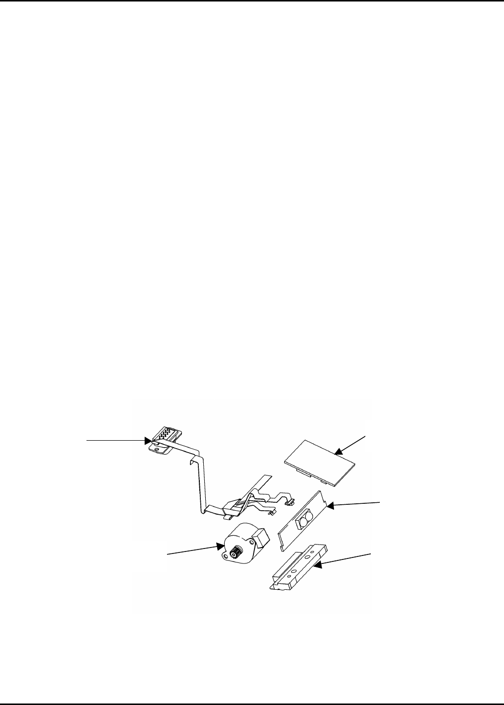
Figure 2-4. Print Module Assembly.
Sensor
Flex
Stepper
Motor
IrDA Processor
PCB Assembly
IrDA PCB
Assembly
Printhead

Physical/Functional Description Confidential 9460 Service Manual
January 2001 Page 9
PRINT MODULE ASSEMBLY
11997501/02
The Print Module contains:
• Sensor Flex Assembly
• Printhead Assembly
• Stepper Motor
• IrDA Processor Assembly (if ordered as an
option-11997502)
Sensor Flex Assembly 119988
The Sensor Flex Assembly contains the on-demand
sensor, die Cut sensor, DB9 and IrDA port connectors.
The on-demand sensor is a dual device that operates as
a retro-reflector. It is mounted in the Print Module
Assembly so that it looks down on the supply as it
exits from the printhead.
The die cut sensor uses the black mark sensor receiver
and an overhead LED to flood the supply with IR light.
When die cut sensing is selected, the start-of-label
position synchronization for each label is accomplished
through the use of a transmissive die cut sensor located
in the Sensor Flex Assembly. The die cut sensor
detects the change in the amount of light passed
through the label liner. The sensors are used to control
the start-of-print position. A proprietary scheme is used
to automatically compensate for differences in sensor
sensitivity as well as for variations in supply and liner
opacity.
Printhead Assembly 119990
The M09460 printhead is a non-intelligent printhead
designed for thermal direct printing. The size, weight,
and physical dimensions of this head are proportionate
with the 2” maximum supply width. Dot-history control
is accomplished with external electronics and the 68336
micro controller. The M09460 printhead has a 1.89”
length print line, comprised of a linear array of 384 dots
with 203 dots per inch. Each dot is spaced at .0049
inches. The electrical interface to the printhead is
through the 68336 micro controller and the PLD.
Stepper Motor 119980
The M09460 supply feed is accomplished by means of
a stepper motor driving an elastomeric drive roller
through a gear train. This drive roller is the platen roller
for the printhead. The actual drive is a friction drive on
the liner or backside of the supply, which is pinched
between the platen roller and the printhead.
The M09460 stepper motor is not more than 25mm in
diameter. The Motorola 68336 TPU, interfaced with
electronic power drivers, controls the motor. The motor
is turned on and off dynamically as required.
The label speeds are 1.5 IPS, 2.0 IPS, and 3.0 IPS.
The operator can choose 1.5 IPS. Otherwise, the
printer will automatically select the fastest print speed
based upon several conditions. The two biggest factors
in determining the print speed are the battery voltage
and the format size. Other factors used to select the
speed are the printhead temperature, the printhead
resistance, and the type of data to be printed. A format
containing a serial bar code, graphics and/or lines may
be printed at a slower speed than a format with only text
and a parallel bar code. There may be some cases
where a 2-inch wide format will not print at 3.0 IPS even
with a fully charged battery.
The M09460 will run at a continuous speed through a
printed label (i.e. it will not change speeds during the
printing of a label or continuous strip of labels). The
uniformity of the motion is sufficient to permit printing of
parallel bar codes of ANSI grade B minimum and serial
bar codes of ANSI grade C minimum on approved label
and tag stocks. The quality of bar codes printed on fax
paper is not guaranteed (only human-readable).
IrDA Processor Assembly
Two PCB’s that are mounted in the Print Module provide
the IrDA option. The 119985 IrDA PCB mounts the
active infrared device, located on the top front of the
Print Module above the printhead. The second PCB is
the IrDA Processor PCB 120280, mounted at the top of
the carrier housing.
BACK INNER CASE
ASSEMBLY 119961S
The Back Inner Case Assembly is made of glass-
reinforced nylon and is the central support for all
mechanical and electrical sub-assemblies in the printer.
It contains the pocket for the battery, as well as
mounting for the serial label, Print Module Assembly,
Main PCB Assembly, Keyboard/Display Assembly and
Back Outer Case Assembly.

9460 Service Manual Confidential Physical/Functional Description
Page 10 January 2001
MAIN PCB ASSEMBLY
119810
The Main PCB Assembly contains the micro controller,
RAM, flash memory, reset circuitry, and the associated
electrical components. The system is designed with
minimum connections in the signal lines between these
basic parts, which form the heart of the system.
The micro controller used in the M09460 is a Motorola
MC68336GCFT20 micro controller operating at 18.35
MHz. This processor is a CPU32 micro controller plus
the additional TPU micro controller. The 68336 micro
controller has a 16 MB addressing range. The 68336
has on board port lines, A/D converter, timers, power
management, and a serial port, providing all the needed
resources on a single chip.
KEYBOARD/DISPLAY
ASSEMBLY
The Keyboard/Display Assembly must be ordered by its
individual components. It is made up of the display flex
120006, keyboard/display PCB 119956, keyboard
119953, display lens 119968, top case 119962, and
boot 11997206/08/09.
The display is used to indicate the status of the printer.
If the printer is in diagnostics mode, the display is used
to lead the operator through diagnostics menus and
display the results of the diagnostics test. The bottom
portion of the display is also used to dynamically
change the functions of the three context-sensitive
keys. Because the display is used differently for each
function of the printer, please refer to the Operator’s
Handbook for a complete description of the display
interface.
The keyboard/display PCB has a graphic display and
switch traces on its top surface. The key portion of the
design is made up of a molded elastomeric material
with conductive sections placed in the center of the
formed keys. The board traces are designed and
positioned under the keyboard so that when a key is
pressed and held, the switch circuit is made.
The keyboard has five keys: power, feed and the three
context-sensitive keys. The power key must be held
down for approximately one second to turn the printer
on or off. The feed key has two basic functions: feed to
top-of-form and as an escape key when in Diagnostics
or Configuration mode. The context-sensitive keys are
used for printer control, configuration and diagnostics.
The keys are used differently, depending on the mode
the printer is in. Refer to the Operator’s Handbook for
more information on the use of these keys.
BACK OUTER CASE
ASSEMBLY 119960S
The Back Outer Case Assembly provides access to the
DB9 serial port through the 119965 door that has
locking slotted screws. It is designed to provide strain
relief to ensure a solid cable connection. Also on this
assembly are two of the four 119970 feet used for shock
resistance and stability.

Confidential
January 2001 Page 11
CHAPTER 3. TROUBLESHOOTING
Troubleshooting the 9460 printer is accomplished through messages displayed by the printer, built-in test
diagnostics, and manual troubleshooting. Certain errors are identified by error codes. Error codes and hardware
failure messages are listed in Appendix A.
Before troubleshooting, always fully charge the battery. Using a discharged battery pack can give false failure
indications.
The information in this chapter assists in identifying and/or confirming the failure of a replaceable module.
Troubleshooting is presented in an “ease of checking”, “most likely to fail--least likely to fail” order. If the
replacement of the indicated modules does not repair the printer, contact Technical Support for additional
assistance.
GENERAL PRINT QUALITY
COMPLAINTS
1. Ensure Front Case Assembly is fully closed and
latched.
2. Ensure supply type and contrast are properly set.
3. Print a diagnostics test pattern. Adjust the printer
as necessary.
4. Verify platen bearings are locked into position.
PRINTS LIGHT IMAGE
ACROSS ENTIRE SUPPLY
1. Replace battery pack with a fully charged unit.
2. Use Setup to verify proper contrast and supply
settings.
3. Verify platen bearings are locked into position.
4. Inspect printhead and platen roller for debris or
damage. Clean as necessary
5. Print a diagnostics test pattern. Adjust printhead
as necessary.
6. Replace supply and retest printing.
7. Replace Print Module Assembly and retest.
8. Check Printhead Flex Assembly. Reseat as
necessary.
9. Replace Platen Roller Assembly and retest.
10. Replace Main PCB Assembly.
PRINTS LIGHT IMAGE ON
ONE SIDE OF SUPPLY ONLY
1. Ensure Front Case Assembly is fully closed and
latched.
2. Verify platen bearings are locked into position.
3. Inspect printhead and platen roller for debris or
damage. Clean as necessary.
4. Print a diagnostics test pattern. Adjust printhead
as necessary.
5. Replace Print Module Assembly and retest.
6. Replace Platen Roller Assembly and retest.
7. Replace Main PCB Assembly.
PRINTS VOIDS ACROSS
PRINT AREA
1. Inspect and clean printhead and platen.
2. Use diagnostics to check for proper contrast and
supply settings.
3. Verify platen bearings are locked into position.
4. Use diagnostics to print test pattern. If voids are
visible and platen rollers are serviceable, problem
may be in the supply.
5. Change supply and retest.

9460 Service Manual Confidential Troubleshooting
Page 12 January 2001
PRINT IMAGE MISSING
DOTS, CREATING A WHITE
LINE THROUGH IMAGE
AREA
1. Inspect and clean printhead and platen.
2. Use diagnostics to check printhead.
3. Use diagnostics to print test pattern. If white line is
still visible, replace Print Module Assembly.
4. Ensure printhead flex is properly seated.
5. Replace Main PCB Assembly.
PRINTS COMPRESSED
IMAGE
1. Inspect and clean paper path and reload supply.
2. Verify platen bearings are locked into position.
3. Replace Print Module Assembly.
4. Replace the Main PCB Assembly.
PRINTER DOES NOT FEED
1. Check battery pack. Recharge or replace as
necessary.
2. Check feed path. Clear/clean as necessary.
3. Ensure Front Case Assembly is closed and
latched.
4. Verify platen bearings are locked into position.
5. If printer still does not feed, replace Print Module
Assembly.
PRINTER SKIPS LABELS
1. Check to ensure printer supply type is correct for
format.
2. Run diagnostics calibration test.
3. If sensor does not adjust:
a. Check sensor and/or Front Flex Assembly
connections.
b. Replace Print Module Assembly or Front
Case Assembly as applicable.
NO DISPLAY AT POWER UP
1. Check battery pack. Charge/replace as necessary.
2. Replace the following items one at a time and
retest:
• Display/Keyboard PCB Assembly
• Print Module Assembly
• Front Case Assembly.
3. If there is a partial or light display, check display by
going to Diagnostics, Display then Pixel.
4. Adjust display contrast as necessary through
Setup, LCD Contrast.
5. Replace Display/Keyboard PCB Assembly.
INCORRECT OR NO
RESPONSE WHEN KEY IS
PRESSED
1. Run diagnostics keyboard test. If one key fails,
replace Keyboard Assembly and retest.
2. If test fails, replace Keyboard/Display Assembly.
3. If still no response, replace Display Flex Assembly.
4. Replace Main PCB Assembly.
NO COMMUNICATIONS
BETWEEN PRINTER AND
HOST
1. Run diagnostics serial port test. If printer fails test,
replace Print Module Assembly.
2. If printer passes loopback test, check/replace data
cable.
3. If communication is still not possible, the problem
is in the computer/host port or the data.
Note: Jumper JP1 must be set to pins 2 and 3 to
properly communicate with a Symbol terminal.
You must visually check that the jumper is on
the top two pins.

Troubleshooting Confidential 9460 Service Manual
January 2001 Page 13
BATTERY CONDITION CHECK
1. A fully charged battery pack should show as close
to the full designator on the display as possible
upon power up of the printer.
2. To verify exact voltage reading, go to Diagnostics,
Printer, then Battery. Readings greater than 8.2
indicate a fully charged battery pack. Readings
less than 7.3 will indicate that the printer is close to
indicating a low battery condition.
PRINTER SHUTS
COMPLETELY OFF WHILE
PRINTING
The printer was printing more than the maximum black
allowable on a format.
1. Reset the printer.
2. Alter the format so there is less black printing on
the format.
Confidential
January 2001 Page 14
CHAPTER 4. DIAGNOSTICS
OVERVIEW
The 9460 printer has a diagnostics utility in flash
memory when it is shipped from the factory. It tests
the capabilities, features, and functions (hardware and
software) of the printer. Customers can use it before
calling Service to obtain diagnostics data that gives an
indication of the problem. Service personnel can also
use it for other tests.
Use diagnostics to
• determine printer configuration.
• perform hardware tests.
• perform service diagnostics.
There is also a Diagnostics Utility (only available to
Service Technicians), which is part of the MPCL
Toolbox.
POWER-UP DIAGNOSTICS
The M09460 performs a power-on self-test before
entering normal operation. This test includes, but is
not restricted to, a RAM test, printhead test, and
battery check.
RAM Test
The RAM test consists of four loops of writing to
memory. Loop one writes a 0x00 pattern to all of
RAM. Loop two verifies the 0x00 pattern while writing
a 0x55 pattern. Loop three verifies the 0x55 pattern
while writing a 0xAA pattern. Loop four verifies the
0xAA pattern while writing 0xFF to clear RAM for
power-up.
Error 900 occurs if this test fails, and the printer will no
longer respond to communications or keypad entry.
Printhead Test
Checks the individual dot element resistance and the
average resistance. If any individual dots test out of
the allowable range, they will be marked as bad. If
more than 10 dots are bad, error 768 occurs. The
user can clear the error, but they cannot print. If 10 or
fewer dots are bad, no error occurs.
If a bar code cannot be positioned correctly for
printing, error 616 occurs.
Battery Check
If the battery voltage is less than 7.3 volts, a low
battery indication will be displayed causing no printer
operation until the battery is recharged.
USER DIAGNOSTICS
Table 4-1. 9460 Printer Menu Structure.
Main Menu Sub Menu Sub Menu Sub Menu
Diagnostics Printer Test Label Diag Label
Test Pattern
Grey Scale
Exit
Sensors Black Mark
Die Cut
On-Demand
Exit
Printhead Dot Test
Dot Resist.
Temperature
Exit
Battery
View Totals Print Inch
Service Inch
Prt High In.
Ser High In.
Exit
Exit
Display Backlight
Pixel
Exit
Keyboard
Comm.
RAM
About
Exit
Online Diag Enable
Disable
Exit
Continued on the next page

Diagnostics Confidential 9460 Service Manual
January 2001 Page 15
Setup Stock
Energy
Standard
Special
High
Energy
Exit
Backlight Disable
Enable
Exit
LCD
Contrast
Printer Contrast
Supply Pos
Print Pos
Margin Adj
Demand
Sensor
Disable
Enable
Exit
Stock
Sensor
Exit
Serial
Comm.
Baud Rate
Parity
Data Bits
Stop Bits
Flow Ctrl
Exit
Power
Mgmt.
Disable
10 seconds
20 seconds
30 seconds
1 minute
2 minutes
5 minutes
10 minutes
30 minutes
1 hour
Exit
Exit
Service Totals View
Modify
Clear
Exit
Sensor Cal Die Cut
Black Mark
On-
Demand
Exit
Virgin
Reset
Boot
Loader
Exit
Exit
Password Entry
To enter the online menu system, you must enter a
password. It is Left A/Left A/Left A/Right A/Left
A. The Main Printer menu appears.
Diagnostics
Displays the Main Diagnostics menu.
Printer
Displays the Printer Diagnostics menu.
Test Label
Displays the Test Label menu.
• Diag Label
Prints a diagnostics label.
• Test Pattern
Prints a test pattern.
• Grey Scale
Prints a grey scale.
• Exit
Returns to the Printer Diagnostics menu
Sensors
Displays the Sensor Diagnostics menu.
• Black Mark
Displays the Black Mark sensor A/D value.
• Die Cut
Displays the Die Cut sensor A/D value.
• On-Demand
Displays the On-Demand sensor A/D value.
• Exit
Returns to the Printer Diagnostics menu.
Printhead
Displays the Printhead Diagnostics menu.
• Dot Test
Runs the Printer Dot test and displays the
results.
• Dot Resist.
Displays the average dot resistance in ohms.
• Temperature
Displays the printhead temperature.
• Exit
Returns to the Printer Diagnostics menu.
Battery
Displays the battery voltage in volts.
View Totals
Displays the printer inches, the service inches, the
printer high inches, and the service high inches.
Exit
Returns to the Main Diagnostics menu.

9460 Service Manual Confidential Diagnostics
Page 16 January 2001
Display
Displays the Display Diagnostics menu.
• Backlight
Turns the backlight on and off (even if the
backlight is disabled).
• Pixel
Turns all display pixels on and off.
• Exit
Returns to the Main Diagnostics menu.
Keyboard
Runs the keyboard test.
Comm.
Prompts the user to install the loopback plug and runs
the diagnostics. It tests all supported baud rates, and
checks the parity and control lines.
Before running this test, take the top of the printer off
and remove the +5 volt jumper. The test fails with the
jumper on.
RAM
Runs the RAM diagnostics.
About
Displays the application and hardware versions.
Exit
Returns to the Main Printer menu.
Online Diagnostics
Sets access to online diagnostics.
• Enable
Enables access to online diagnostics.
• Disable
Disables access to online diagnostics.
• Exit
Returns to the Main Printer menu.
Setup
Displays the Setup Main menu.
Stock Energy
Sets the type of supply being used.
• Standard
Standard supplies are being used.
• High Energy
Synthetic or linerless supplies are being used.
• Exit
Returns to the Setup Main menu.
Backlight
Enables or disables the backlight.
• Enable
Turns the backlight on.
• Disable
Turns the backlight off.
• Exit
Returns to the Setup Main menu.
LCD Contrast
Sets the contrast of the display.
Printer
Displays the Printer Setup menu.
• Contrast
Adjusts the print contrast.
• Supply Pos
Adjusts the supply position.
• Print Pos
Adjusts the print position.
• Margin Adj
Adjusts the margin position.
• Demand Sensor
Enables or disables the on-demand sensor.
• Stock Sensor
Changes the sensor type and automatically
enters into the calibration routine for that
sensor.
• Exit
Returns to the Setup Main menu.

Diagnostics Confidential 9460 Service Manual
January 2001 Page 17
Serial Comm.
Displays the Serial Communications Setup menu.
• Baud Rate
Selects the baud rate.
• Parity
Selects the parity.
• Data Bits
Selects the number of data bits.
• Stop Bits
Selects the number of stop bits.
• Flow Control
Selects the flow control.
• Exit
Returns to the Setup Main menu.
Power Mgmt.
• Disable
Disables power management.
• 10 sec. – 1 hour
Selects the timeout by selecting one of the
values ranging from 10 seconds to 1 hour.
• Exit
Returns to the Setup Main menu.
Exit
Returns to the Main Printer menu.
Service Diagnostics
Prompts the user for a password and starts the
service diagnostics. The password is Right
A/Center A/Left A/Center A /Right A. The
Service Main menu appears.
Totals
Displays the Totals menu.
• View
Displays the number of inches moved in the
printer, including forward and backwards
motion. Both print inch (total inches) and
service inch totals can be viewed.
• Modify
Allows the service technician to modify the
print inch and service inch totals.
• Clear
Allows the service technician to clear both the
print inch and/or service inch totals.
• Exit
Returns to the Service Main menu.
Sensor Cal
Allows the service technician to select a sensor to
perform a sensor calibration with installed supplies.
When the sensor type is changed in the Setup Main
menu, the sensor calibration routine is automatically
accessed to ensure accurate supply feeding.
Virgin Reset
Resets the printer to the state in which the customer
received it.
Boot Loader
Places the printer into boot loader mode.
Exit
Returns to the Main Printer menu.
Exit
Returns to the Ready prompt.

9460 Service Manual Confidential Diagnostics
Page 18 January 2001
MONARCH INITIALIZATION
FILES (.MIF)
.MIF files specify parameters for the printer. They
provide a quick and easy way to alter certain aspects
of the printer’s activity from the system defaults.
To load a .MIF file, use the Monarch Flash Utility, and
then reboot the printer. To change the parameters,
reflash the printer with a new .MIF file. To return the
printer to the system defaults, do a virgin reset.
To create a .MIF file, use any text editor, such as
Microsoft® Windows® Notepad. Following is an
example:
[MONARCH M9460]
LOW_POWER = time
SUPPLY_POS = rows
FLOW = flowvalue
LEFT_OFFSET = rows
REFL_MIN = value
TRANS_MIN = value
REPRINT = setting
ON_DEMAND = setting
COM = baud, parity, databits, stopbits, flowcontrol
END
Note: The bold lines are required. The parameters
can appear in any order.
Following are the parameters:
Parameter Possible Values
LOW_POWER
The time before the printer
goes into sleep mode.
1 - 7200 seconds
SUPPLY_POS
The amount of supply that
feeds out of the printer.
-99 - 99 dot rows
FLOW
Flow control. 0 None
11 DTR/DSR
12 RTS/CTS
21 XON/XOFF
LEFT_OFFSET
How far from the left side
of the supply that the
printer can print (RCL
only).
-99 – 99 dot rows
REFL_MIN
The minimum reflectance
A/D count to determine the
black mark.
0 – 255
Parameter Possible Values
TRANS_MIN
The minimum transmissive
A/D count to determine the
black mark.
0 – 255
REPRINT
Sets the ability for the
printer to be able to reprint
a batch.
0 Disabled
1 Enabled
ON_DEMAND
Sets the hardware
capability to use on
demand printing.
0 Disabled
1 Enabled
COM
The communication
parameters to use. Values
in bold are the defaults.
baud
1200, 2400, 4800,
9600, 19200, 38400,
57600, 115200
parity
N (None), E (Even),
O (Odd)
databits
7, 8, or 9
stopbits
1 or 2
flowcontrol
N (None), D
(DTR/DSR), R
(RTS/CTS), X
(XON/XOFF)

Diagnostics Confidential 9460 Service Manual
January 2001 Page 19
PC DIAGNOSTICS
The Monarch MPCL Toolbox software includes more
service diagnostics. See Chapter 7 for more
information.
IMMEDIATE COMMANDS
There are two 9460 MPCL immediate commands for
service use only, as follows.
Command Description
^MF Uploads the .MIF file from the
printer to the host.
Command Description
^MS Uploads information about the flash
file system contents from the printer
to the host. For each file, it uploads
the type, the file ID, and the file
size. For example:
FONT :1001 4016
FONT :1002 5040
FONT :1003 6720
FONT :1004 3808
FONT :1005 5216
FONT :1006 2880
FONT :1007 3984
FONT :1008 4800
FONT :1009 5840
FONT :1010 3648
FONT :1011 4976
FONT :1013 13440
FORMAT :1018 60
FORMAT :1019 60
FORMAT :1016 60
FORMAT :1015 60
MIF :-001 40
18 file(s) 68104 bytes
259514 free
Confidential
January 2001 Page 20
CHAPTER 5. TESTS AND ADJUSTMENTS
Because of the complex test fixtures required to build
the sub-assemblies in the printer, Service will replace
by sub-assembly instead of by component. There are
no mechanical or electrical adjustments that can be
done in the field apart from what is available through the
configuration packets in MPCL. These adjustments are
available through the keyboard (refer to Chapter 4 for
details) and through the MPCL Toolbox.
MAIN PCB ASSEMBLY
There are two potentiometers on the Main PCB and one
jumper.
RV1
This potentiometer sets the +5 VDC A to D reference
voltage and should NOT be adjusted in the field. It can
be verified on pin 8 of D14.
RV2
This potentiometer controls the LCD Contrast. Adjust
the LCD contrast through the Setup menu and NOT
with this adjustment. (This adjustment will be removed
at PCB level AG.)
JP1
This jumper is normally on pins 1 and 2 to allow for DTR
flow control. If a printer will be cable connected to a
Symbol terminal, this jumper must be set to pins 2 and
3. There is no way to sense this connection. Remove
the Back Outer Case to verify the jumper connection.
Note: Pin 1 is the bottom pin, so for Symbol terminal
connectivity, the jumper MUST be on the top
two pins.
BATTERY TEST
You can check the battery by the built-in gauge on the
display, through printer diagnostics, or the MPCL
Toolbox.
To enter into MPCL Toolbox Diagnostics mode, you
must enable online diagnostics on the printer and be at
the Ready prompt.
A fully charged battery should be greater than 8.2 VDC,
a battery requiring a charge should be less than 7.3.
Any battery pack less than 6.8 VDC should be
replaced.
SENSOR CALIBRATION
All three sensors should be calibrated through Service
diagnostics (as described in Chapter 4) or MPCL
Toolbox diagnostics.
To enter into MPCL Toolbox Diagnostics mode, you
must enable online diagnostics on the printer and be at
the Ready prompt.
Sensor High Low Delta
Black Mark >3.92 VDC
(on white)
<2.94 VDC
(on black)
1 VDC
Die Cut >2.50 VDC
(liner only)
<2.40 VDC
(liner and
supply)
1 VDC
On Demand 0.196 VDC
PRINTHEAD VERIFICATION
The printhead can be tested by printer diagnostics or
MPCL Toolbox diagnostics.
To enter into MPCL Toolbox Diagnostics mode, enable
online diagnostics on the printer and be at the Ready
prompt.
Standard average resistance of the printhead is 350
ohms with an individual dot range of 245-455.

Confidential
January 2001 Page 21
CHAPTER 6. DISASSEMBLY PROCEDURES
TOOLS REQUIRED
• 3/32 Allen wrench
• #1 Phillips screwdriver
• small straight slot screwdriver
REMOVING THE BOOT,
11997203/06/08
1. Remove the optional strap assembly, if present.
2. Remove 2 M4X16mm socket head cap screws
securing the strap buttons, and remove the strap
buttons.
3. Remove the boot.
4. Reassemble in reverse order.
REMOVING THE BACK
OUTER CASE, 119960S
1. Remove the boot.
2. Remove the battery and supplies.
3. Unscrew the 2 captive M4X16mm slotted screws on
the DB9 door.
4. Open the front case, and remove 2 #4X3/8" plastite
screws (one on each side of the battery).
5. Slide a small, straight-slot screwdriver along the
sides between the inner and outer casework and
gently push inner case out to disengage tabs.
6. Pull the back outer case down from the top cover,
and away to the rear.
Assembly Note
Slide the back outer case under the DB9 door,
119965 and case top, 119962 until the ribs on each
side snap into the slots on the back inner case,
119960. Be careful not to pinch the Front Flex
Assembly between the back inner and outer cases.
7. Reassemble in reverse order.
REMOVING THE DB9 DOOR
1. Remove the boot.
2. Remove the back outer case.
3. Carefully spread the pins on the DB9 door, and
remove them from the slots in the Back Inner Case
Assembly.
4. Reassemble in reverse order.
REMOVING THE CASE TOP
1. Remove the boot.
2. Remove the back outer case.
3. Remove the DB9 door.
4. Remove 2 #4X3/8" plastite screws securing the
case top to the back inner case (on either side of
the DB9 connector).
5. Unsnap the case top from the back inner case
assembly. (4 places).
6. Reassemble in reverse order.
REMOVING THE
KEYBOARD/DISPLAY
ASSEMBLY
1. Remove the boot.
2. Remove the back outer case.
3. Remove the DB9 door.
4. Remove the case top.
5. Lift the Keyboard/Display Assembly from the 4
bosses, and unfold it upward to gain access to the
Display Flex ZIF connector CN8. Disconnect the
flex from the Keyboard/Display Assembly.
6. Reassemble in reverse order.

9460 Service Manual Confidential Disassembly Procedures
Page 22 January 2001
REMOVING THE CPU BOARD
ASSEMBLY
1. Remove the boot.
2. Remove the back outer case.
3. Remove the DB9 door.
4. Remove the case top.
5. Remove the Keypad/Display Assembly.
6. Carefully slide the DB9 connector from the back
inner case.
7. Disconnect the DB9/OD/die cut sensor split flex
from the ZIF connector CN3, the stepper motor
harness from CN2, and the RF link/black mark
sensor flex from ZIF connector CN9.
8. Carefully pry the three contacts from the back inner
case using a small flat blade screwdriver.
9. Lift the bottom of the CPU board with corner
mounts off of the posts, and rotate it up while
pulling the board free from the top corner mounts.
10. Disconnect the printhead flex from ZIF connector
CN7.
11. Reassemble in reverse order.
REMOVING THE PRINT
MODULE
1. Remove the boot.
2. Remove the back outer case.
3. Remove the DB9 door.
4. Remove the case top.
5. Remove the Keypad/Display Assembly.
6. Remove the CPU Board Assembly.
7. Remove the compression spring from the boss on
the back inner case. Using a small screwdriver or
spring hook, compress the spring from the top, and
disengage it from the tabs on the back of the Print
Module Assembly. Then, rotate it out. Be careful
not to lose it.
8. Remove the hinge pin securing the Print Module
Assembly to the back inner case.
9. Slide the Print Module Assembly out the front of
the back inner case while carefully guiding the 2
flexes and the stepper motor harness through their
respective slots in the back inner case.
10. Reassemble in reverse order. Be careful when
threading the flexes and harness through the back
inner case.
REMOVING THE FRONT
CASE ASSEMBLY
1. Remove the boot.
2. Remove the back outer case.
3. Disconnect the RF link/black bark sensor flex from
ZIF connector CN9, and remove the tape holding
the flex to the back inner case.
4. Remove the hinge pin, and unlatch the Front Case
Assembly.
Assembly Note
While holding the flex up against the bottom of the
back inner case, align the holes of the Front Case
Assembly and back inner case, and carefully install
the hinge pin. When properly assembled, the flex
will be between the hinge pin and the bottom of the
back inner case.
5. Reassemble in reverse order.
RETROFITTING TO IrDA
1. Remove outer case.
2. Remove front case assembly
3. Remove PCB.
4. Remove top case assembly.
5. Remove print module.
6. Unsnap the two halves of the print module
assembly and separate them, watching for the
spring.
7. Gently snap the IRDA PCB assembly in half to
separate the LED and processor assemblies.
8. Slide the LED connector leg of the flex through the
right side slot of the casework.
9. Connect the processor leg of the flex to the PCB
and curl up to slide into the casework.
10. Slide the printhead and tear bar in.
11. Carefully reposition all harnesses and the spring,
and then slide the casework back together.
12. Attach the LED connector leg of the flex to the
PCB and roll the LED PCB to fit into the slot on the
top of the casework.
13. Re-assemble in reverse order.
Confidential
January 2001 Page 23
CHAPTER 7. PC DIAGNOSTICS
The Printer Diagnostics utility is one of the
components of the MONARCH MPCL Toolbox
software. The Printer Diagnostics utility mimics the
functionality available in the Manufacturing Sendfile
program.
Using the Printer Diagnostics utility you can:
• download files to the printer.
• display MUX values.
• test the printhead.
• display service totals.
• display stock history.
• upload images.
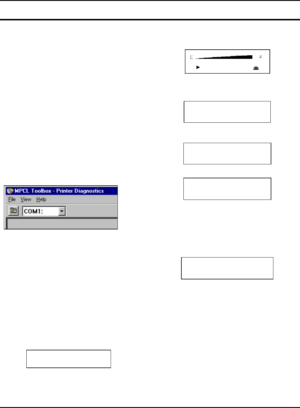
The Printer Diagnostics utility uses the
communication port settings last used by one of the
other Toolbox utilities. If you need to change the
Comm port, select the Comm port (COM1-COM4)
from the drop-down list box. To start using the
Printer Diagnostics utility, you must first detect the
printer. See "Detecting the Printer."
ENABLING ONLINE
DIAGNOSTICS
To use the Printer Diagnostics utility, enable online
diagnostics on the printer.
The default setting for online diagnostics is disable.
To use these diagnostics, you must reset it to
enable every time you turn on the printer. Follow
these steps to enable online diagnostics.
1. Turn the printer on by pressing and holding
down the power button until the display turns on.
The display flashes printer version information
and then you will see:
Ready
p
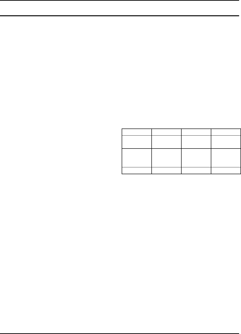
2. Press the A button under the p icon. You will
see the battery indicator E (empty) and F (full).
3. Press the A button under the toolbox icon to
enter diagnostics. You will see:
Diagnostics
Online Diag.
E D
4. Scroll until Online Diag. is highlighted. Select
Online Diag. You will see:
Enable
Disable
E D
5. Select Enable. You will see:
Online Diag
Enabled
E x
The online diagnostics are turned on.
6. Press the A button under the x icon or press
the F button to exit.
To disable online diagnostics:
1. From the Online Diagnostics menu, select
Disable. You will see:
Online Diag
Disabled
x
The online diagnostics is turned off.
2. Press the A button under the x icon or press
the F button to exit.
9460 Service Manual Confidential PC Diagnostics
Page 24 January 2001
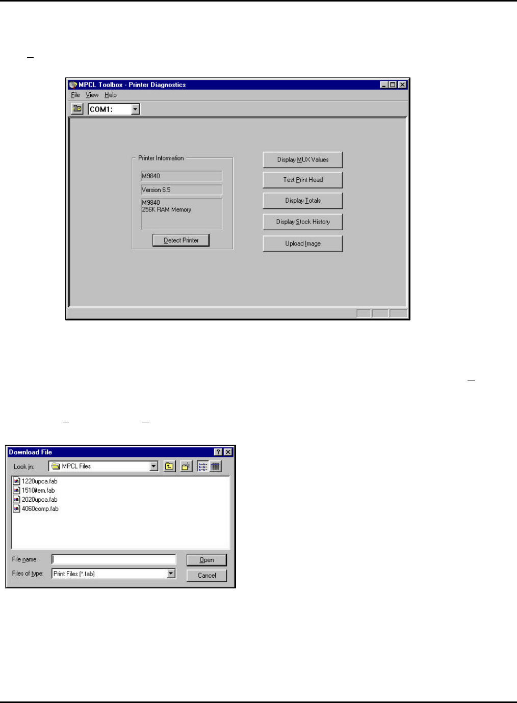
DETECTING THE PRINTER
Click Detect Printer to sense which printer is
connected and start using the utility. The model
being tested and the software version number
displays.
DOWNLOADING FILES TO
THE PRINTER
You can download format and batch (*.FAB) files
and others to the connected printer.
1. From the File menu, select Download... You will
see
2. Highlight the file to download and click Open.
You see the message "Downloading..." while the
file is sent. Four sample format and batch files
are provided with this utility and saved in the
C:\Program Files\Monarch Marking\MPCL Files
directory. Change directories to send additional
formats you have created.
PC Diagnostics Confidential 9460 Service Manual
January 2001 Page 25
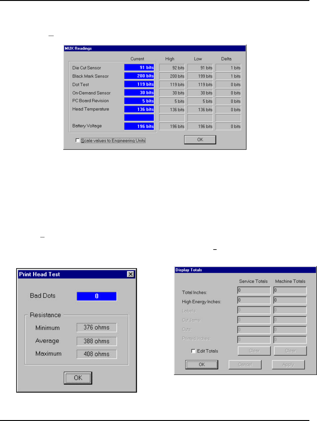
DISPLAYING MUX VALUES
1. Click Display MUX Values to show the current values for each sensor, contrast setting, printhead
temperature, battery voltage, and more.
The current voltages for the sensors are constantly monitored and updated. The displays correspond to
the channels of the A/D converter on the CPU board. The high, low, and Delta readings are also
displayed.
2. Click f when you finished looking at the MUX values. You return to the main screen.
TESTING THE PRINTHEAD
1. Click Test Print Head to perform a printhead
test. The test checks for bad dots on the
printhead. Depending on your printer, you may
be able to print with up to four bad dots on the
printhead.
2. Click f when you are finished performing
the printhead test. You return to the main
screen.
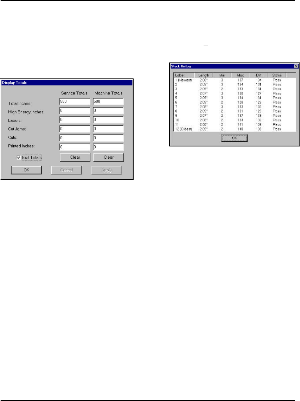
DISPLAYING SERVICE
TOTALS
1. Click Display Totals to display and modify the
Service and Machine totals.
9460 Service Manual Confidential PC Diagnostics
Page 26 January 2001
2. Click Edit Totals to modify the totals. You will be
prompted to enter a password. After entering
the password, click f. (The password for
modifying the service/machine totals is the
common password [jmartin] for Monarch
Marking service personnel.) If you enter the
wrong password, you can still view the Service
and Machine totals, but you cannot change
them. If you entered the correct password, you
will see
3. Click Clear to clear the total inches for Service
or the machine. You can also adjust the high
energy inches, labels, cut jams, cuts, and/or
printed inches.
4. Click Apply to save the new settings.
5. Click f when finished changing the totals. If
you click f before clicking Apply, the
message, "Values have been modified, update
printer? Yes or No." appears. Click Yes or No
to continue. If you click Yes, the message, "This
will change the internal values on the printer,
continue? Yes or No." appears. Click Yes or No
to continue. If you click Yes, the values are
modified.
DISPLAYING STOCK
HISTORY
1. Click Display Stock History to display the stock
quality of the most recently printed labels/tags.
You will see
2. Label 1 represents the most recently printed
label or tag. If only one label has been
fed/printed, there will be information only for
label 1.
The length is displayed in inches. The Min
and Max are A/D readings used to
determine feature location. The status
indicates whether the printer viewed this
label a good or bad label length.
3. Click f when you are finished viewing the
stock history.
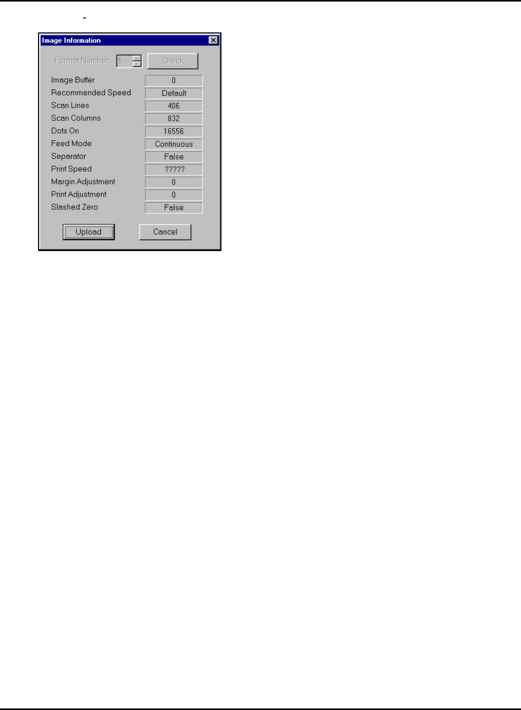
UPLOADING IMAGES
This feature allows you to upload an image from the
printer's image buffer to a .BMP file. If you need to
show a sample label in a .DOC or .XLS file, you can
import the .BMP into your file. This eliminates the
need to scan label samples.
To upload an image:
1. Download a file to the printer. You need an
image in the printer's image buffer.
PC Diagnostics Confidential 9460 Service Manual
January 2001 Page 27
2. Click Upload Image. You will see Information about the image is displayed,
such as the length and width of the image
in dots (scan lines and scan columns), if
batch separators are enabled, and the
margin/print adjustments.
3. Click Upload. The message "Receiving data"
appears while the image is sent from the
printer's image buffer to the PC and converted
to a .BMP file. The .BMP file is a true black and
white Windows DIB BitMap file. Any program
that can display BMP files can view this.
4. If installed, Microsoft Windows launches the
Paint program and displays the file/format in
your printer's image buffer. Use the Paint
program to make any changes to the .BMP file
and save it.

Confidential
January 2001 Page 28
APPENDIX A. ERROR CODES
This appendix provides a listing of error codes that may be generated by the 9460 printer.
001 Format ID number must be 1 to 99.
002 Name must be a printer-assigned name or be 1 to 8 characters inside quotes.
003 Action must be A (add) or C (clear).
004 Supply length is invalid (maximum is 4").
005 Supply width is invalid (maximum is 2").
006 Storage device must be R (volatile RAM).
007 Unit of measure must be E (English), M (Metric), or G (Dots).
010 Field ID number is outside the range 0 to 999.
011 Field length exceeds 2710.
012 Row field position is greater than the maximum stock dimension.
013 Column field position is greater than the maximum stock dimension.
014 Font style is invalid.
015 Character rotation must be 0 (0 degrees), 1 (90 degrees), 2 (180 degrees), or 3 (270 degrees).
016 Field rotation must be 0 (0 degrees), 1 (90 degrees), 2 (180 degrees), or 3 (270 degrees).
017 Field restriction must be V (variable) or F (fixed).
018 Code page selection defined in the field must be 1 (ASCII).
020 Vertical magnification must be 1 to 7.
021 Horizontal magnification must be 1 to 7.
022 Color must be B, D, O, R, or W.
023 Inter-character gap must be 0 to 99 dots.
024 Field justification must be B (balanced), C (centered), E (end), L (left), or R (right).
025 Data length is too long.
030 The bar code height is invalid (minimums are 1 (English), 2 (Metric), 1 (Dots)) or is not within the supply
dimensions.
031 Human readable option must be 1 (no CD or NS), 5 (NS at bottom, no CD), 6 (CD at bottom, no NS), 7
(CD and NS at bottom) or 8 (no text).
033 Bar code density is invalid.
040 Line thickness must be 0 to 99 dots.
041 Line direction must be 0, 90, 180, or 270.
042 End row is invalid. Line segment or box end row is defined outside of printable area.

Error Codes Confidential 9460 Service Manual
January 2001 Page 29
043 End column is invalid. Line segment or box end column is defined outside of printable area.
044 Dot pattern for line or box must be "" (literally just two double quotes).
045 Line length is defined beyond the maximum length of 3.72".
046 Line type must be S (segment) or V (vector).
051 Imaging value is defined as something other than 0.
101 The format referenced by the batch is not in memory.
102 Print quantity is outside the range 0 to 25.
104 Batch mode must be N (new) or U (update).
105 Batch separator in a batch control field must be 0 (Off).
106 Print multiple is outside the range 1 to 999.
107 Cut multiple is out of range.
108 Multiple part supply is outside the range 1 to 5.
109 Cut type specified is invalid.
200 Option number must be 1, 31, 50, 51, or 52.
201 Copy length is outside the range 0 to 255.
202 Copy start position must be 1 to 255.
203 Destination start position must be 1 to 255.
204 Source field must be 0 to 999.
205 Copy type must be 1 (copy after rules) or 2 (copy before rules).
206 Increment/Decrement selection must be I (increment) or D (decrement).
207 Incrementing start position must be 0 to 255.
208 Incrementing end position must be 0 to 255.
209 The incrementing amount must be 0 to 999.
210 Security value for a PDF417 bar code must be 0 to 8. Correct the value and resend the format to the
printer.
211 Narrow element value is less than 1 or greater than 99. Correct the value and resend the format to the
printer.
212 Wide element value is less than 1 or greater than 99. Correct the value and resend the format to the
printer.
213 Dimension must be 1 to 30 for a column or 3 to 90 for a row on a PDF417 bar code.
214 Truncation code must be S (standard) or T (truncated bar code).
215 Aspect code must be C (columns) or R (rows).
216 Option definition must be S (set) or T (template).
217 Input device must be D (Default), H (Host), K (Keyboard), N (None), or S (Scanner).
218 Pad direction must be L (from left) or R (from right).
219 Pad character is outside the range 0 to 255.
220 Check digit selection must be G to generate the check digit.
221 Primary or secondary price format is outside the range 1 to 15.
222 Data type restriction is outside the range of 1 to 6.
223 Option is not valid for the field.
224 Bar code inter-character gap must be 0 to 99 dots. (This value is also known as the additional
character gap when using Option 50, Defining Bar Code Densities.)
251 Power up mode must be 0 (online).
252 Language selection must be 0 (English) or 4 (other).
253 Batch separator code in a supply setup packet must be 0 (off).

9460 Service Manual Confidential Error Codes
Page 30 January 2001
254 Slash zero selection must be 0 (standard zero).
255 Supply type must be 0 (black mark) or 1 (die cut).
256 Ribbon selection must be 0 (direct) or 1 (transfer).
257 Feed mode must be 0 (continuous) or 1 (on-demand).
258 Supply position is outside the range.
259 Contrast adjustment must be -390 to 156 dots.
260 Print adjustment must be -99 to 99 dots.
261 Margin adjustment must be -99 to 99 dots.
262 Speed adjustment must be 0 (1.0 IPS).
263 Primary monetary symbol is invalid.
264 Secondary symbol selection must be 0 (none) or 1 (print secondary sign).
265 Monetary decimal places must be 0 to 3.
266 Character string length in the control characters packet must be 5 (MPCL control characters) or 7
(ENQ/IMD command characters)
267 Baud rate selection must be 0 (1200), 1 (2400), 2 (4800), 3 (9600), 4 (19200), or 5 (38400). Resend the
communication settings packet.
268 Word length selection must be 0 (7 bits) or 1 (8 bits). Resend the communication settings packet.
269 Stop bits selection must be 0 (1 bits), or 1 (2 bits). Resend the communication settings packet.
270 Parity selection must be 0 (none), 1 (odd), or 2 (even). Resend the communication settings packet.
271 Flow control selection must be 0 (none), 1 (DTR), 2 (CTS/RTS), or 3 (XON/XOFF). Resend the
communication settings packet.
272 Internal code page selection must be 1 (ASCII).
273 Cut adjustment must be -99 to 99 dots.
282 RS232 Trailer string is too long. Use a maximum of 3 characters.
283 ENQ Trailer string is too long. Use a maximum of 3 characters.
284 The buffer type must be T (Transmit), R (Receive), I (Image), F (Format), or D (Downloadable Fonts).
285 The storage device type in the memory configuration packet must be R (volatile RAM).
286 The buffer size is invalid.
287 The printhead width must be 244 to 812 dots.
288 The battery voltage must be 0 (15-volt battery) or 1 (12-volt battery).
289 The printer address specified in the communication settings packet must use exactly six characters.
290 Action must be 0 (disable), or 1 (enable) for the backfeed control packet or the printer is active.
291 Dispense position must be 50 to 200 dots and the backfeed distance is greater than the dispense
position or the printer is active.
292 Backfeed distance must be 10 to 200 dots or the printer is active.
310 Check digit scheme number must be 1 to 10.
311 Modulus must be 2 to 11.
314 Check digit algorithm must be D (sum of digits) or P (sum of products).
325 Duplicating direction must be 0 (insert after) or 1 (insert before) in duplicate fields for graphics.
327 Amount of row adjustment must be 0 to 999 dots in duplicate fields for graphics.
328 Duplicate count must be 0 to 999.
340 Bitmap line encoding must be H (hex) or R (run length).
350 Font selector must be 1 to 9999.
351 Font data length must be 68 to 16384.

Error Codes Confidential 9460 Service Manual
January 2001 Page 31
352 Insufficient memory is available for the downloaded font.
380 Job request is invalid. Must be 0 to 4.
400 The character immediately following { is invalid.
401 Internal software failure.
402 Field separator is not in the expected location.
403 Record separator was not found.
404 Bad token, number, or string is too long.
405 Too many fields exist in the format. You cannot have more than 1000 fields in the format.
409 The printer memory is full. Delete unnecessary formats or graphics from memory. If you are using a
graphic file that is very large, consider using another mapping method (such as run length encoding) to
reduce the required memory.
410 Parity on the printer does not match the parity on the host. Check the parity setting under SETUP
options.
411 Framing error. The printer cannot communicate with the host. Make sure the host is turned on,
communication cables are connected correctly, port settings are correct, and communications are
active. Check the baud rate, word length, and stop bits to make sure they match those at the host. Do
not toggle between Microsoft Windows and MS-DOS while using the COPY command, or you will
receive a framing error. Exit Windows before using the COPY command. Re-transmit the data.
412 There is a problem with flow control between the printer and the host. Make sure the printer and the
host flow control settings match (both are DTR or both are XON/XOFF).
413 Online receive queue is full. Check your printer's XON/XOFF or DTR SETUP values to be sure there is
not a flow control problem.
414 The internal keyboard buffer is full or you need a new keyboard.
415 The buffer size you defined exceeds the total available in your machine.
420 Internal software list error.
421 Internal software list error.
422 Duplicate internal name.
424 Internal software list error.
425 Internal software list error.
426 Internal software list error.
427 Internal software list error.
428 Internal software list error.
429 A field number appears more than once in a format.
430 The format uses a graphic file that cannot be found.
433 No format field for batch data record.
497 Parallel loopback test failed.
499 Serial loopback test failed.
571 Bar code length error.
572 Copy length error.
573 Price length error
574 No CD scheme or room for CD. The CD scheme in the batch does not fit the format or the field
contains blanks.
575 The graphic included in your format could not be found.
601 Error occurred while imaging.
603 Batch not found for imaging.
611 Font, bar code or density is invalid. The font, bar code or density in the batch does not fit the format.
612 The data in this line of the batch is either missing or does not match the format.

9460 Service Manual Confidential Error Codes
Page 32 January 2001
613 Reference point off tag.
614 Portion of field off tag. There may be an invalid character in the packet. Make sure you did not enter
the letter O for the number 0.
615 Internal overfull error.
616 Dot shifting failed. A bad dot falls on a bar code that cannot be shifted.
618 Magnification must be 1 to 7.
619 Bad JIS code for Kanji.
703 Calibration of different sized black marks.
704 Printer is out of supplies or has not sensed a supply mark within the specified number of inches.
Check the supply tracking, supply marks, black mark sensor position, and supply roll for binding.
Press the A button under the x icon to clear the error. Change the supply.
750 Printhead is overheated. Turn off the printer to let the printhead cool.
751 Printer did not sense a black mark when expected. The supply may be jammed. For errors 751-753,
Check the supply tracking, supply marks, black mark sensor position, and supply roll for binding.
If the error continues to appear, change the supply.
752 The printer sensed a mark in the wrong place.
753 The printer sensed a mark that is too long.
754 Ribbon fault.
755 Printhead is open.
756 The printer is out of supplies. Load supplies.
757 Load supplies. The calibrated supply length differs by plus or minus .25 inches from the format.
758 Check supply. Either the on-demand sensor is broken, or the supply is not seen. Adjust the on-
demand sensor so it is over a white area on the supply, or set the unit to continuous mode.
759 Knife not moving.
760 Knife jammed.
761 Stacker is full.
763 Waiting to dispense label. Press the feed button.
764 Verifier failure.
765 Printhead failure. You need a new printhead.
766 Overfeed/Backfeed failure.
768 The printhead has more than 10 bad dots or is not connected. Make sure the printhead is connected
and if necessary, call Customer Service to order a new printhead or printhead kit.
790 The printer is busy. Turn off the printer. Wait two seconds and turn it back on. Resend the packets.
800 A directory in flash memory is full.
801 Flash memory is full.
802 A directory in flash memory cannot be found.
803 There is no directory in flash memory.
810 A file in flash memory is not open.
811 A file in flash memory is already open.

Error Codes Confidential 9460 Service Manual
January 2001 Page 33
812 The file in flash memory is full.
813 You cannot access flash memory.
820 An error occurred in the flash program.
821 An error occurred while erasing flash memory.
822 There is a flash ID error.
900 RAM test failure.
904 No configuration memory for native layer.
906 Power failure.
907 No configuration memory for application layer.
909 RAM is corrupted.
910 Warm start.
911 Virgin restart.
930 Error occurred while erasing flash memory.
931 Error occurred while writing to flash memory.
932 Error occurred while writing to RAM.
933 Communication parity error.
934 Communication framing error.
935 Communication buffer overrun.
936 Invalid record type.
937 Invalid hex data.
938 Invalid checksum.
939 Invalid record count.
940 Flash address is illegal.
950-999 AMD 29K illegal interrupt codes.
SYSTEM ERROR
VECTOR ##
## can be:
2 Bus Error
3 Address Error
4 Illegal Instruction
5 Zero Division
6 CHK, CHK2 Instructions
7 TRAP Instructions
8 Privilege Violation
9 Trace
10 Line 1010 Emulator
24 Spurious Interrupt
48 User-defined vectors (48-255)
This error is fatal. If you receive it, reset and/or reflash the printer.
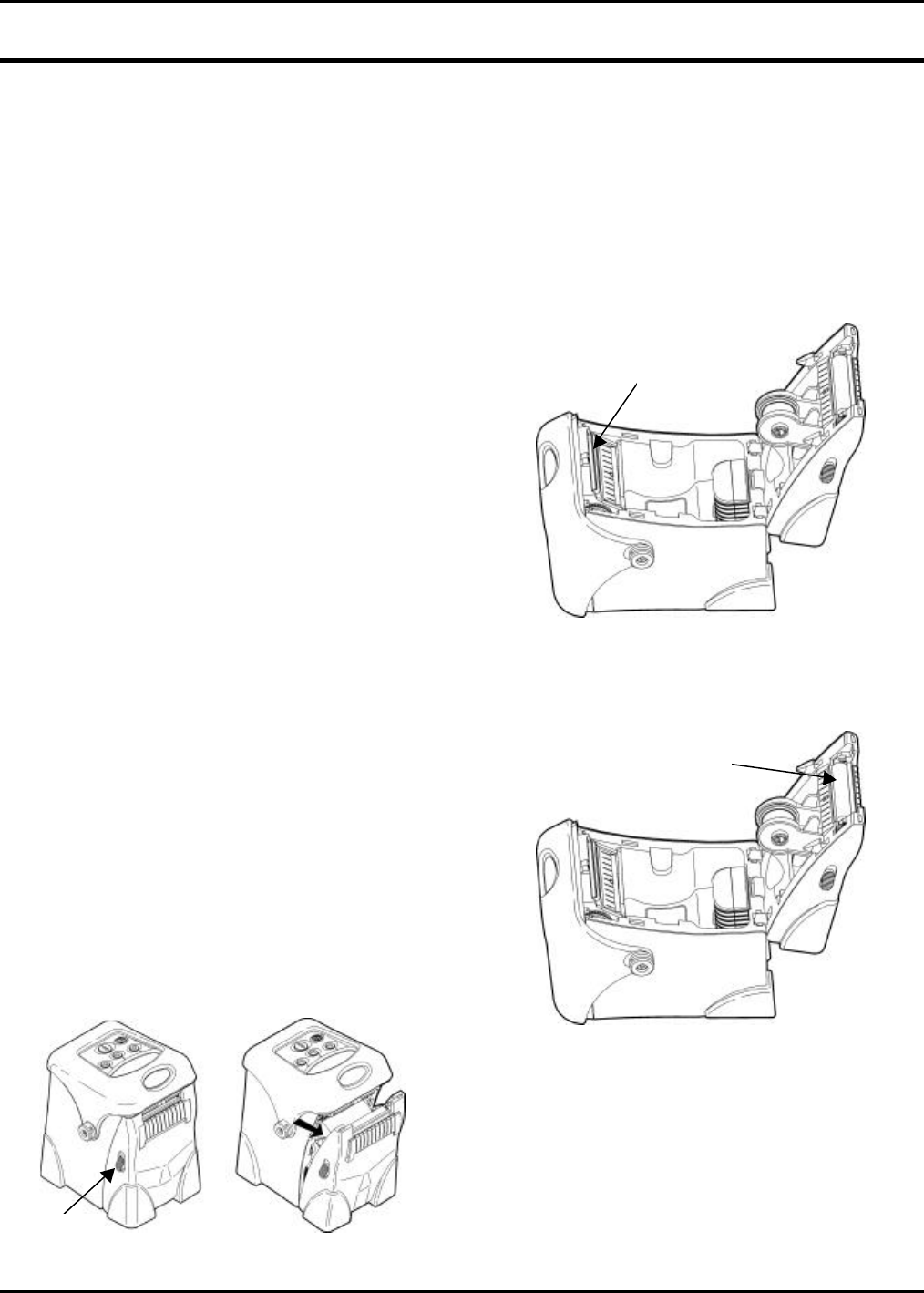
Confidential
January 2001 Page 34
APPENDIX B. CARE & MAINTAINENCE
This chapter explains how to
• clean the printhead, platen roller, and the
supply sensors.
• clear label jams.
Caution: Do not use sharp objects to clean the
printhead. This may damage the printer
and require a service charge.
CLEANING
The rate and frequency at which you print determines
how often you must clean the printer.
You may need to clean the printhead and platen roller
• after using seven to ten (7-10) rolls of
supplies.
• in extreme temperatures, humid conditions or
a dirty environment.
• when you see voids in the print.
• after a label jam.
You may have to clean the supply sensors more often
if you frequently receive supply error messages.
Use any of the following items to clean the printhead:
• a soft cloth moistened with isopropyl alcohol
Caution: Use isopropyl alcohol on the
interior areas only; never use it on
the exterior.
• a Monarch cleaning pen (part number
114226)
To clean the printhead, platen roller, and supply
sensors:
1. Turn off the printer by pressing and holding the P
button until the display is blank.
2. Open the supply door by pushing down on the
release buttons on both sides of the printer. The
supply door should swing open.
3. Lay the printer on its back.
4. Caution: Ground yourself by using your field
service static kit.
5. Clean the printhead with a clean soft cloth
moistened with isopropyl alcohol, a cleaning pen,
or a small brush.
Note: Do not use sharp objects to remove
adhesive or label particles from the
printhead area.
6. Clean the platen roller with a cleaning pen or a
clean soft cloth moistened with isopropyl alcohol.
7. Turn the platen roller with your finger to clean the
entire surface.
Release
Button
Printhead
Platen Roller
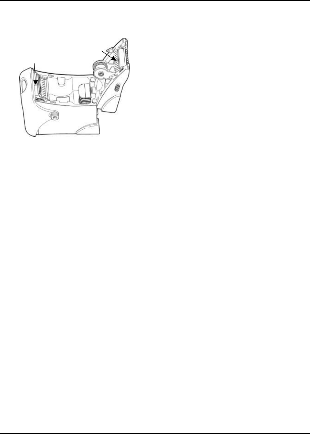
Care & Maintenance Confidential 9460 Service Manual
January 2001 Page 35
8. Clean the on-demand and black mark sensors
with a cleaning pen or a clean soft cloth
moistened with isopropyl alcohol.
9. Reload the supply.
10. Close the supply door until the release buttons
click into place.
11. Turn on the printer by pressing and holding the P
button until the display turns on.
CLEARING LABEL JAMS
When you are printing and jam occurs, you see a
supply error message. To clear the jam:
1. Turn off the printer by pressing and holding the P
button until the display is blank.
2. Open the supply door by pushing down on the
release buttons on both sides of the printer. The
supply door should swing open.
3. If necessary, remove the roll of supplies.
4. Remove the jammed supplies and reload the
supply.
5. Close the supply door.
6. Turn on the printer by pressing and holding the P
button until the display turns on.
On-Demand
Sensor
Black
Mark
Sensor
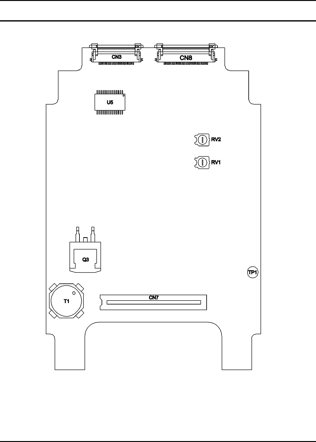
Confidential
January 2001 Page 36
APPENDIX C. CIRCUIT CARD ASSEMBLY LAYOUTS
Figure C-1. Main PCB (Primary Side).
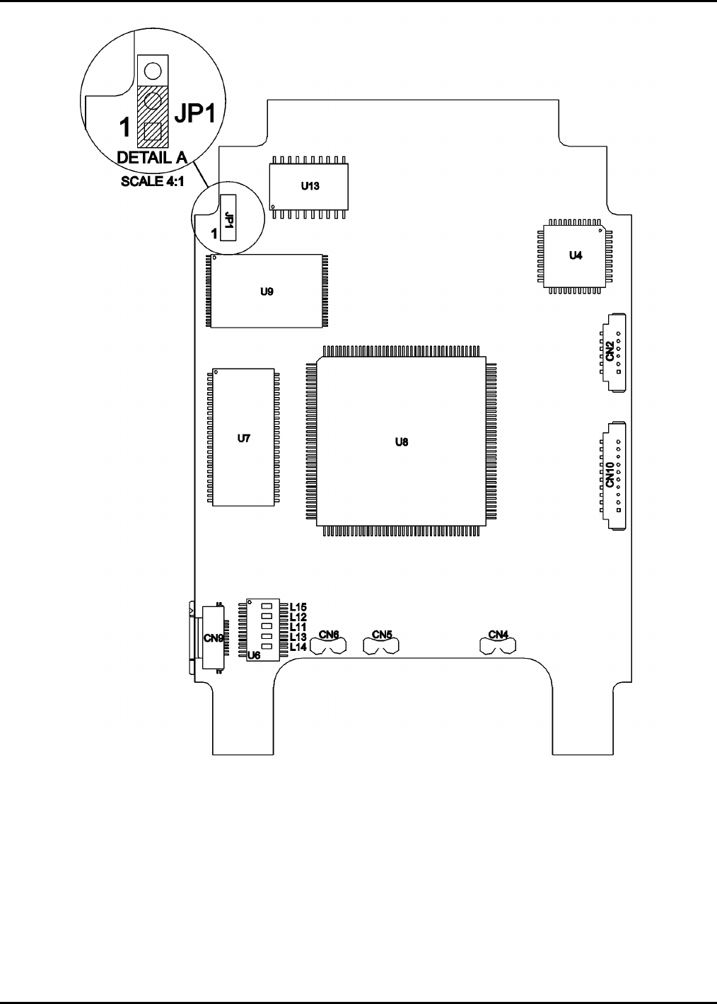
Circuit Card Assembly Layouts Confidential 9460 Service Manual
January 2001 Page 37
Figure C-2. Main PCB (Secondary Side).
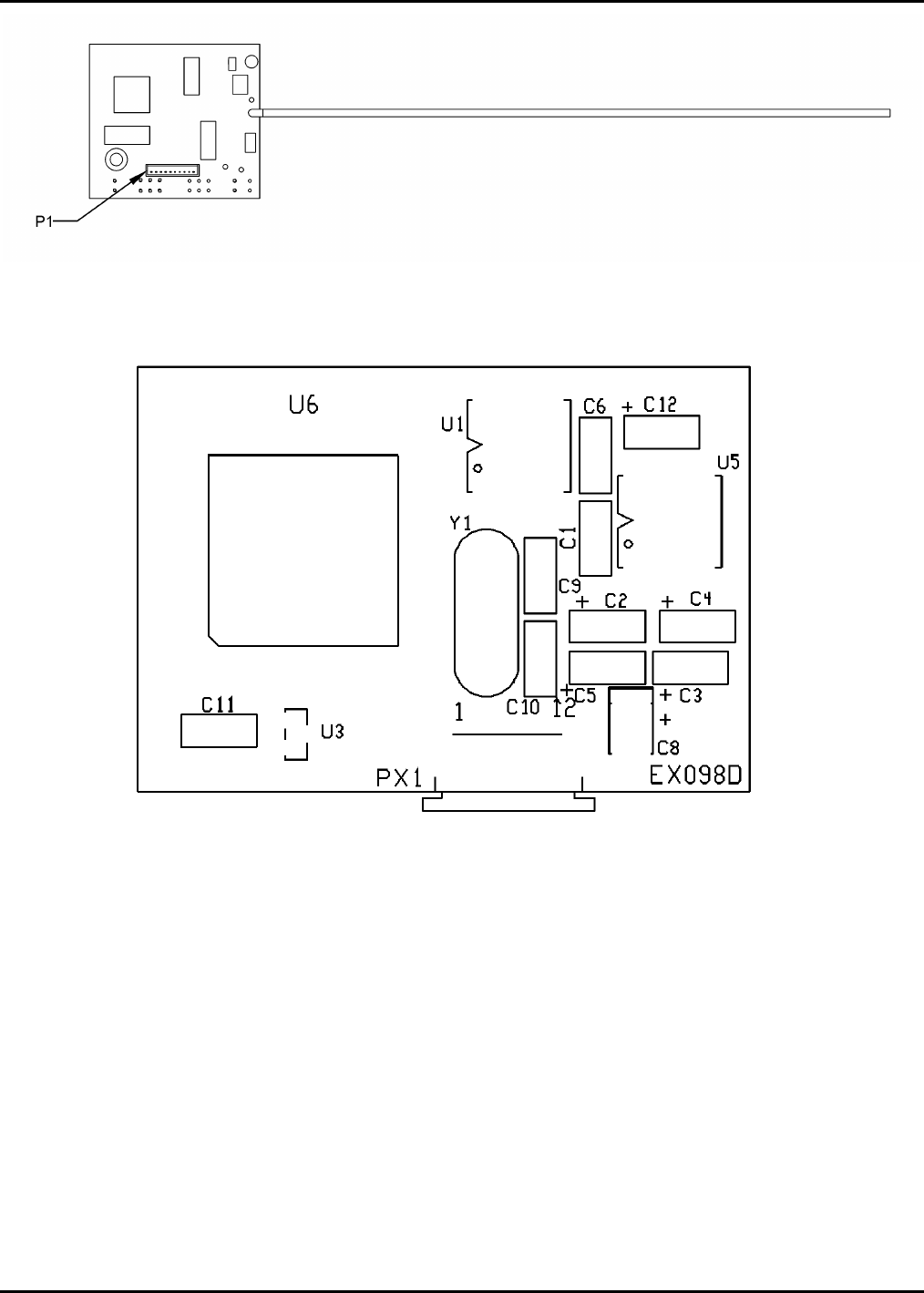
9460 Service Manual Confidential Circuit Card Assembly Layouts
Page 38 January 2001
Figure C-3. RF PCB.
Figure C-4. IrDA Processor Board.
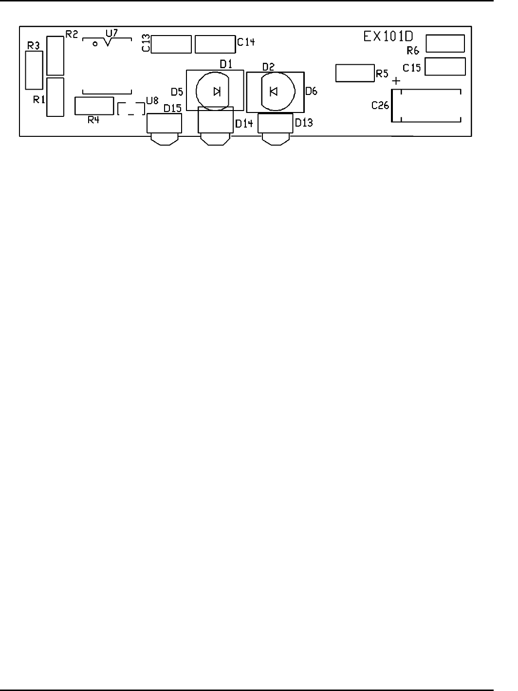
Circuit Card Assembly Layouts Confidential 9460 Service Manual
January 2001 Page 39
Figure C-5. IrDA Transceiver.