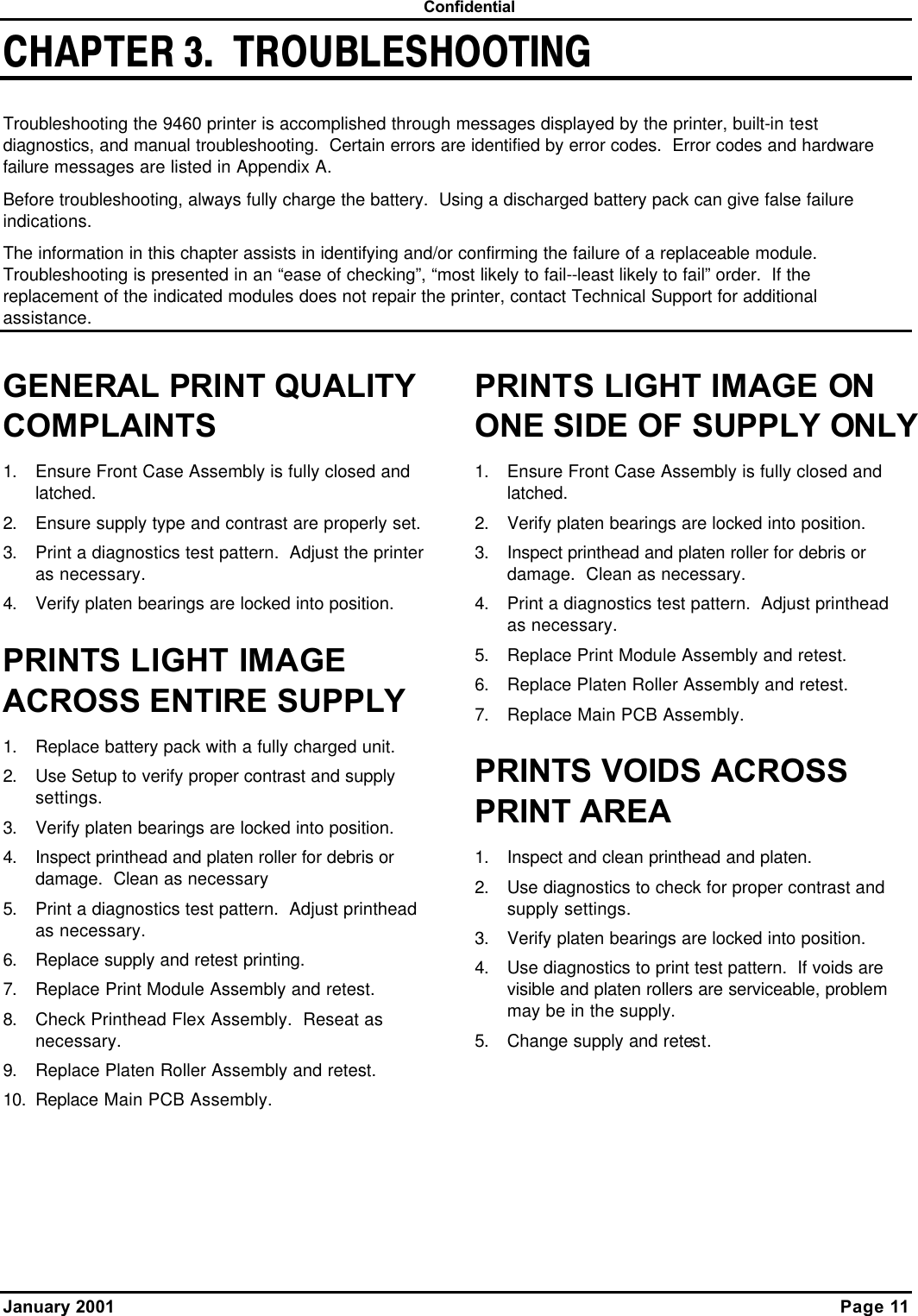
Avery Dennison Retail Information Services 9460IPLA3021 Wireless Printer User Manual 9460SMCV
Avery Dennison Retail Information Services, LLC Wireless Printer 9460SMCV
Contents
- 1. Manual
- 2. Service manual
- 3. Symbol manual
- 4. Radio confiuration
Service manual
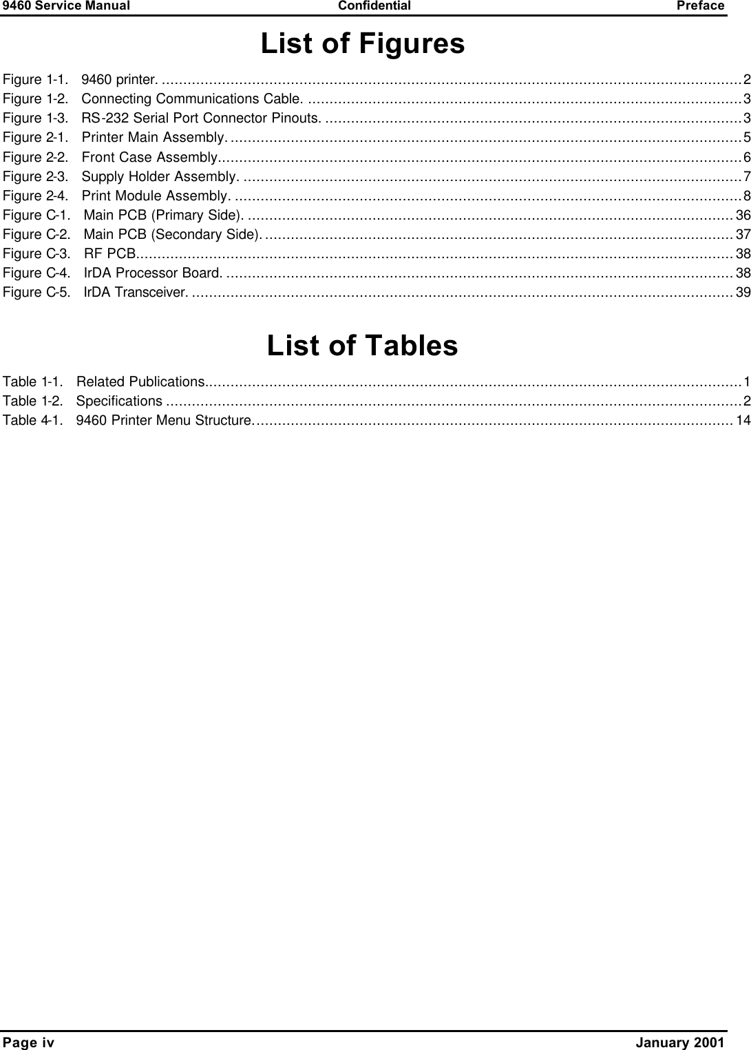
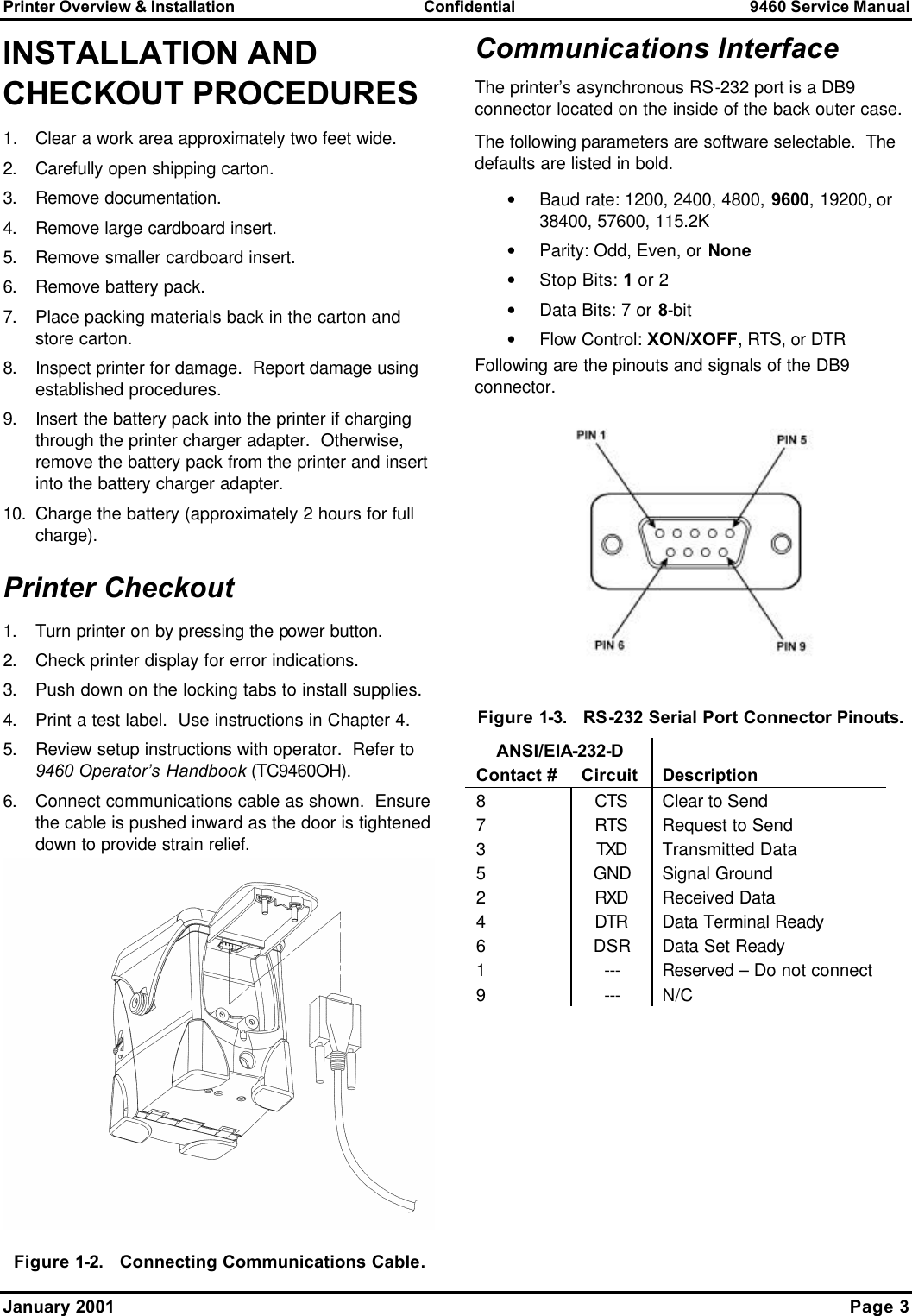

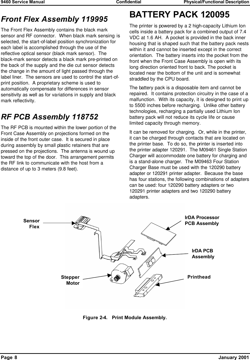


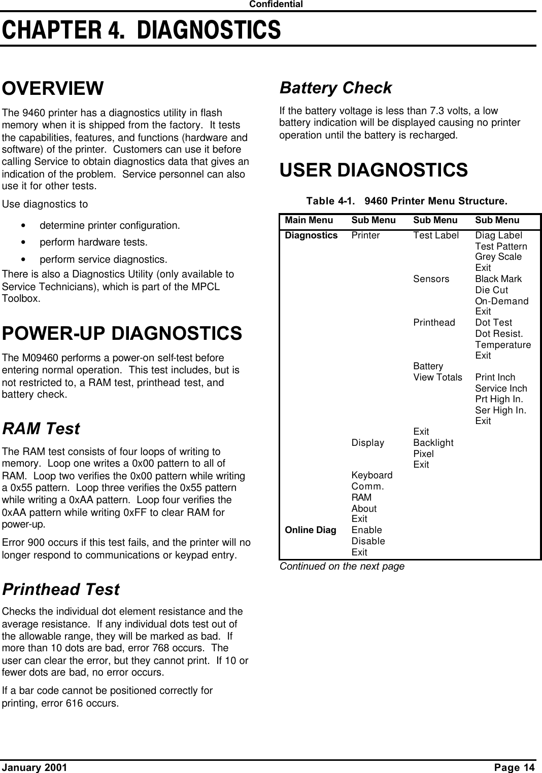
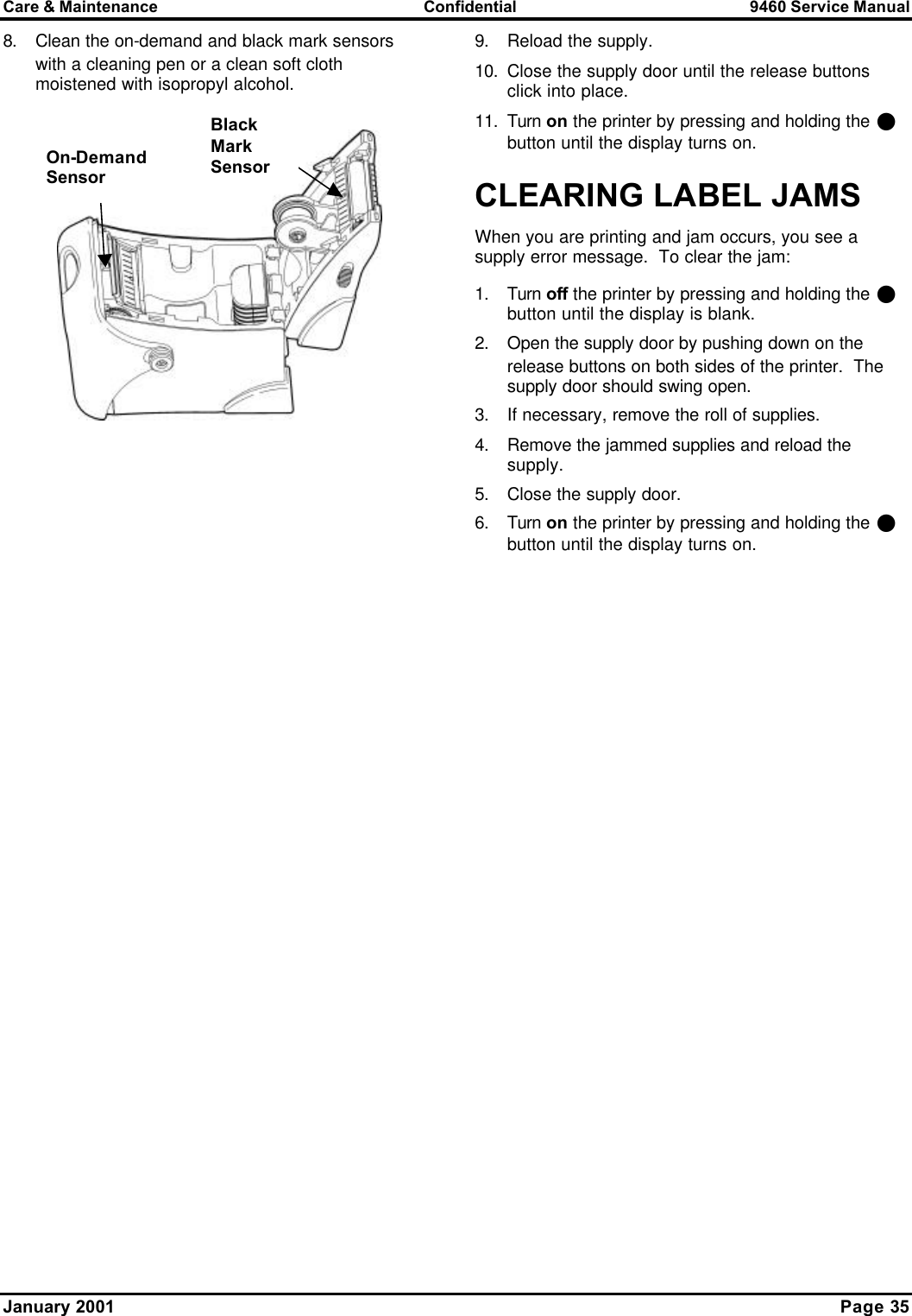
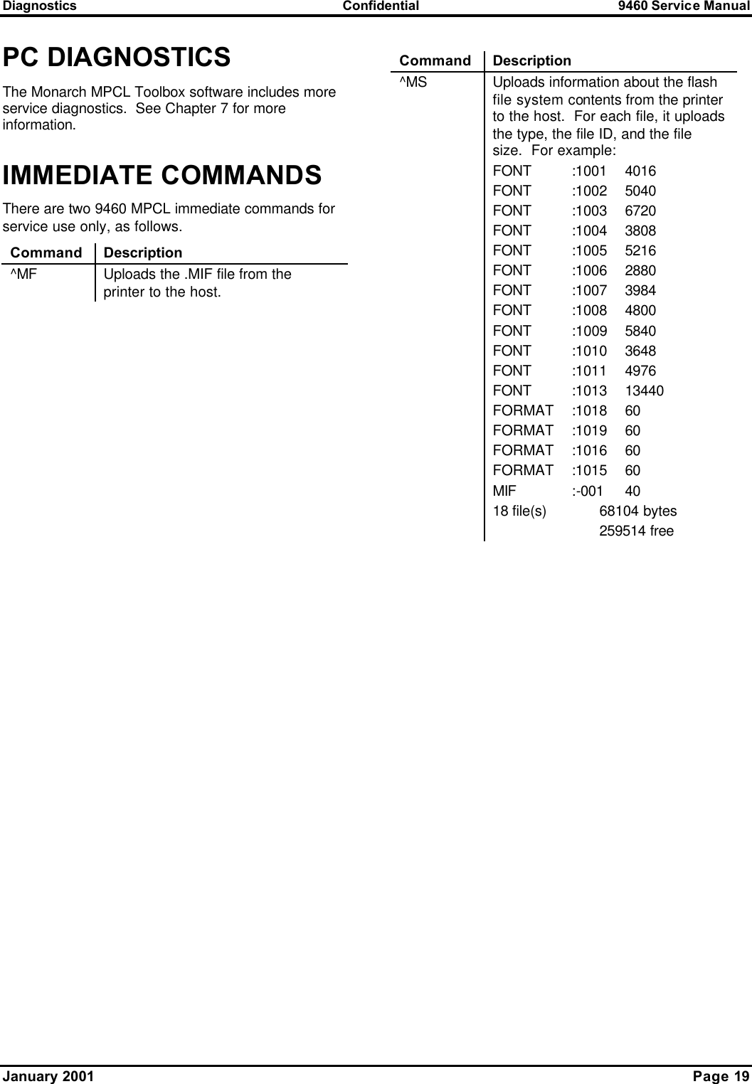
![9460 Service Manual Confidential Diagnostics Page 18 January 2001 MONARCH INITIALIZATION FILES (.MIF) .MIF files specify parameters for the printer. They provide a quick and easy way to alter certain aspects of the printer’s activity from the system defaults. To load a .MIF file, use the Monarch Flash Utility, and then reboot the printer. To change the parameters, reflash the printer with a new .MIF file. To return the printer to the system defaults, do a virgin reset. To create a .MIF file, use any text editor, such as Microsoft® Windows® Notepad. Following is an example: [MONARCH M9460] LOW_POWER = time SUPPLY_POS = rows FLOW = flowvalue LEFT_OFFSET = rows REFL_MIN = value TRANS_MIN = value REPRINT = setting ON_DEMAND = setting COM = baud, parity, databits, stopbits, flowcontrol END Note: The bold lines are required. The parameters can appear in any order. Following are the parameters: Parameter Possible Values LOW_POWER The time before the printer goes into sleep mode. 1 - 7200 seconds SUPPLY_POS The amount of supply that feeds out of the printer. -99 - 99 dot rows FLOW Flow control. 0 None 11 DTR/DSR 12 RTS/CTS 21 XON/XOFF LEFT_OFFSET How far from the left side of the supply that the printer can print (RCL only). -99 – 99 dot rows REFL_MIN The minimum reflectance A/D count to determine the black mark. 0 – 255 Parameter Possible Values TRANS_MIN The minimum transmissive A/D count to determine the black mark. 0 – 255 REPRINT Sets the ability for the printer to be able to reprint a batch. 0 Disabled 1 Enabled ON_DEMAND Sets the hardware capability to use on demand printing. 0 Disabled 1 Enabled COM The communication parameters to use. Values in bold are the defaults. baud 1200, 2400, 4800, 9600, 19200, 38400, 57600, 115200 parity N (None), E (Even), O (Odd) databits 7, 8, or 9 stopbits 1 or 2 flowcontrol N (None), D (DTR/DSR), R (RTS/CTS), X (XON/XOFF)](https://usermanual.wiki/Avery-Dennison-Retail-Information-Services/9460IPLA3021.Service-manual/User-Guide-319436-Page-24.png)
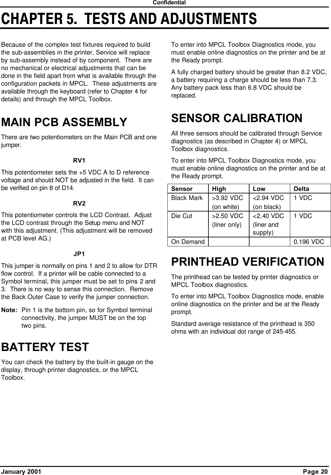
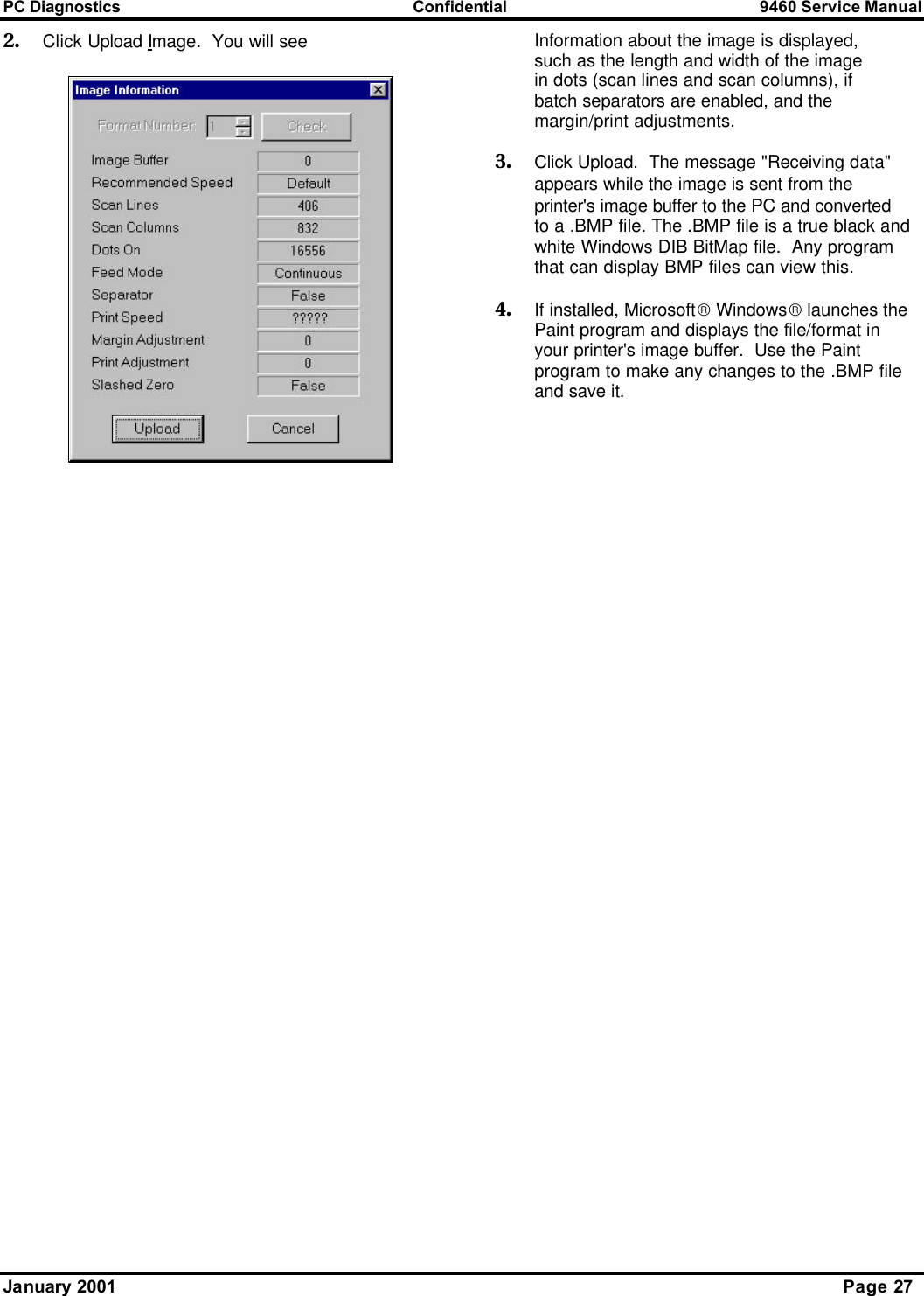
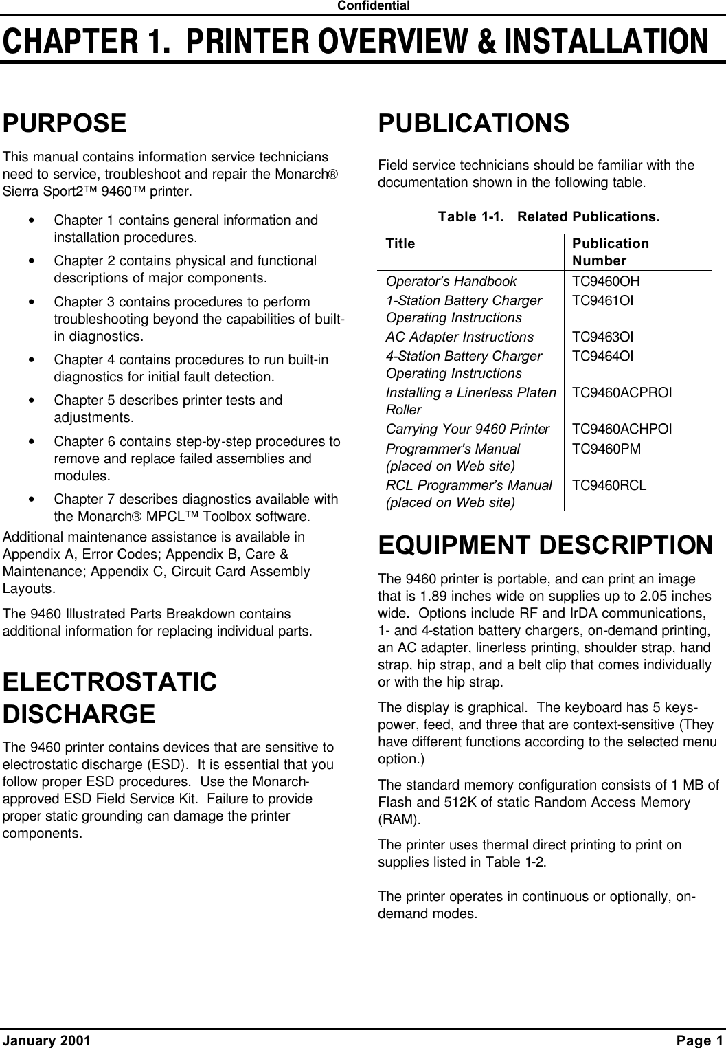
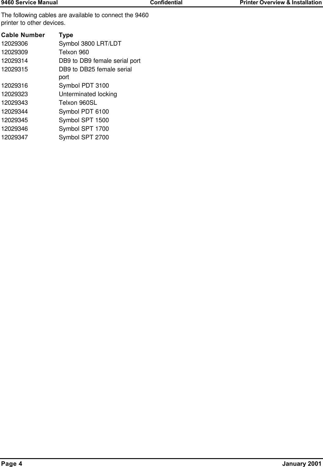
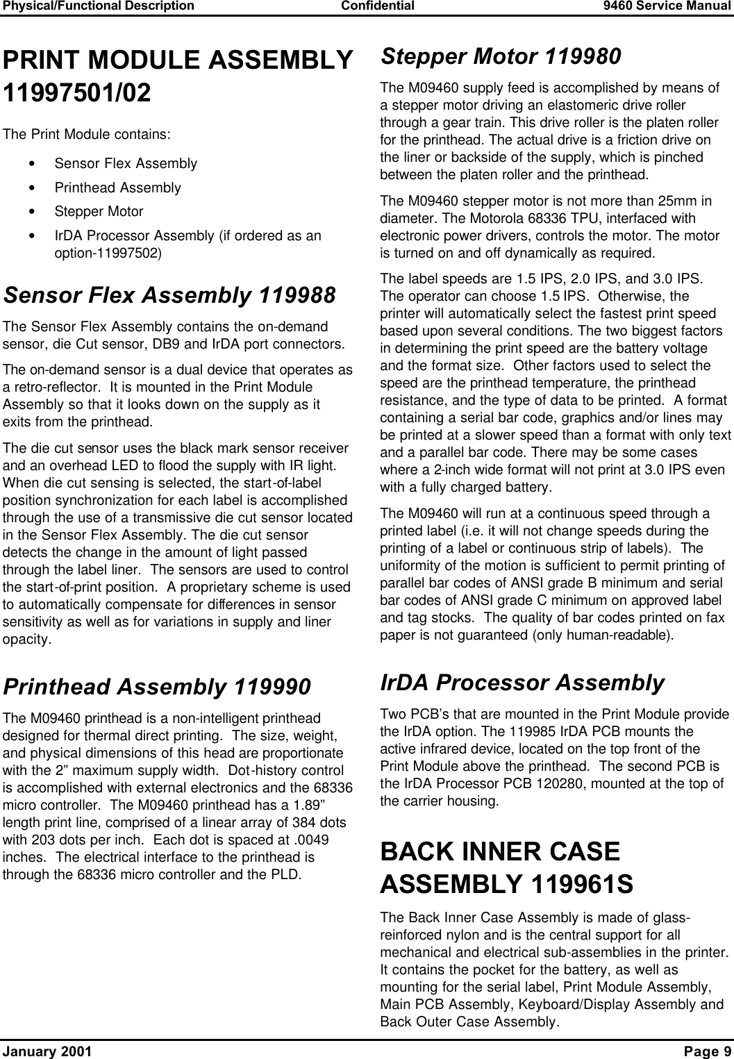
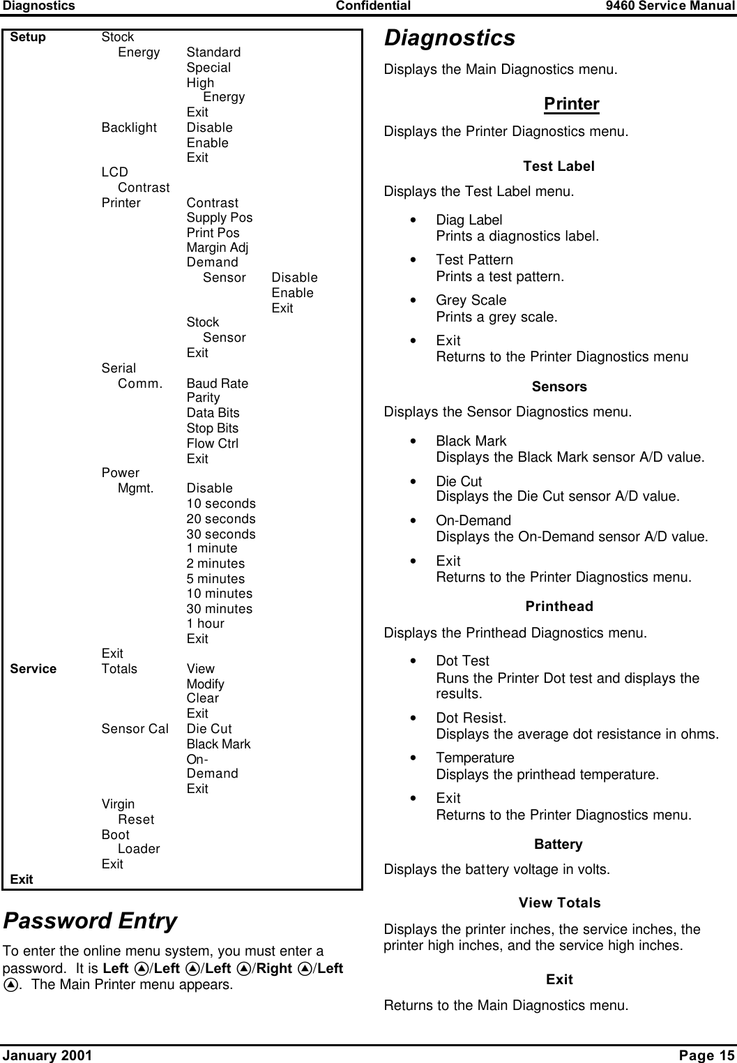
![9460 Service Manual Confidential PC Diagnostics Page 26 January 2001 2. Click Edit Totals to modify the totals. You will be prompted to enter a password. After entering the password, click f. (The password for modifying the service/machine totals is the common password [jmartin] for Monarch Marking service personnel.) If you enter the wrong password, you can still view the Service and Machine totals, but you cannot change them. If you entered the correct password, you will see 3. Click Clear to clear the total inches for Service or the machine. You can also adjust the high energy inches, labels, cut jams, cuts, and/or printed inches. 4. Click Apply to save the new settings. 5. Click f when finished changing the totals. If you click f before clicking Apply, the message, "Values have been modified, update printer? Yes or No." appears. Click Yes or No to continue. If you click Yes, the message, "This will change the internal values on the printer, continue? Yes or No." appears. Click Yes or No to continue. If you click Yes, the values are modified. DISPLAYING STOCK HISTORY 1. Click Display Stock History to display the stock quality of the most recently printed labels/tags. You will see 2. Label 1 represents the most recently printed label or tag. If only one label has been fed/printed, there will be information only for label 1. The length is displayed in inches. The Min and Max are A/D readings used to determine feature location. The status indicates whether the printer viewed this label a good or bad label length. 3. Click f when you are finished viewing the stock history. UPLOADING IMAGES This feature allows you to upload an image from the printer's image buffer to a .BMP file. If you need to show a sample label in a .DOC or .XLS file, you can import the .BMP into your file. This eliminates the need to scan label samples. To upload an image: 1. Download a file to the printer. You need an image in the printer's image buffer.](https://usermanual.wiki/Avery-Dennison-Retail-Information-Services/9460IPLA3021.Service-manual/User-Guide-319436-Page-32.png)