BTS BTSWEMG2 Wireless EMG sensor for EMG system User Manual ERFNC 00782 16 FREEEMG 300 ENG v 4 0 3
BTS SpA Wireless EMG sensor for EMG system ERFNC 00782 16 FREEEMG 300 ENG v 4 0 3
BTS >
Contents
- 1. EREMB-01091-06 FREEEMG 100 RT User Manual ENG v.2.0.3
- 2. ERFNC-00782-16 FREEEMG 300 User Manual ENG v.4.0.3
- 3. ERTMJ-00998-04 TMJOINT User Manual ENG v.3.0.0
ERFNC-00782-16 FREEEMG 300 User Manual ENG v.4.0.3

BTS FREEEMG
version 4.0.3
user manual
english
Document Number : ERFNC-00782-16
Published: June 2013
Copyright © 2010 - 2013 BTS SpA. All Rights Reserved.

1
BTS
Bioengineering
BTS FREEEMG
contents 1
icons, symbols and acronyms 5
radio regulation 9
disposal (WEEE) 10
intended use 11
regulatory label 12
acquisition unit regulatory label 12
EMG wireless probes regulatory label 12
AUX wireless probes regulatory label 13
BTS charger regulatory label 14
BTS docking station regulatory label 14
warnings 15
copyright 18
introduction 19
general description 19
case contents 20
system components 24
physical description 24
acquisition unit 25
PDA (Personal Digital Assistant) 27
wireless EMG probes 29
wireless FSW/EGN probes (optional) 33
on-o analysis (optional) 34
electrogoniometers (optional) 35
charger 36
contents

2
BTS
Bioengineering
BTS FREEEMG
contents
docking station (optional) 38
installation 43
user PC minimum conguration 43
installation of the Wi-Fi interface 43
description of the software on the user PC 45
switching on BTS FREEEMG 300 45
rst connection 47
connection check 48
correct data visualization check 50
acquisition protocol 52
tting the patient 57
guide to the use of onboard software 60
initial screen 60
“Active” button 60
selecting the work mode 64
description of the main bars and menu 65
protocol 68
probes setup 69
digital oscilloscope (gane) 72
digital oscilloscope (cross check) 75
footswitches 77
“Local” button: holter mode 78
“Remote” button: lab mode 91
“Download” button 95
“Cong” button 97
“Exit” button 106
BTS FREEEMG 300 updating 107
updating the onboard software 107
creating a backup image 108

3
BTS
Bioengineering
BTS FREEEMG
contents
maintenance and cleaning 110
appendix A – technical specications 113
wireless probes 113
receiving unit 113
BTS internal coding 114
appendix B – environmental specications 116
appendix C – power supply and switch o 117
appendix D – battery 118
appendix E – declaration of conformity 120
appendix F – troubleshooting guide 121
1708 error - Incorrect IP address or port set up 121
1709 error - Impossibility to connect to the unit 122
backup restoring 122
receiving unit hardware reset 124
5
BTS
Bioengineering
BTS FREEEMG
icons, symbols and acronyms
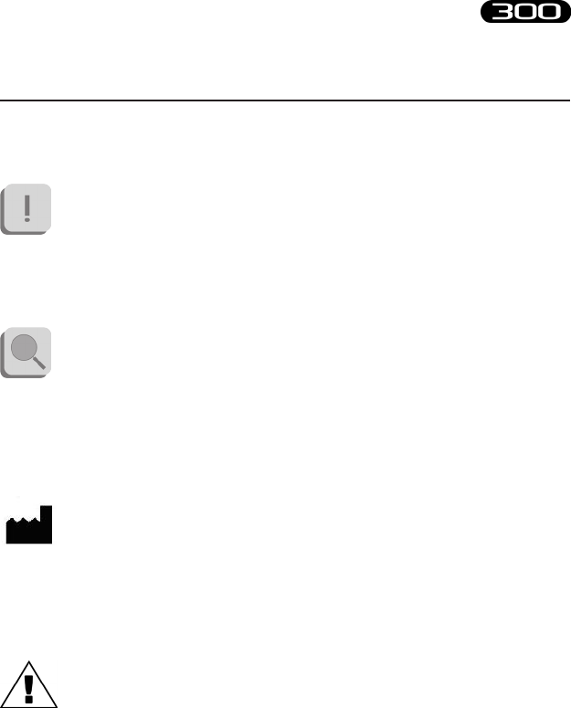
Symbol in the instructions for the function.
e icon represents the information which requires special attention.
Symbol in the instructions for the function.
is icon makes reference to a more detailed discussion of the subject in
hand.
Symbol on the equipment:
e data appearing next to the manufacturer’s symbol refer to the place of
manufacture of the equipment itself.
Symbol on the equipment:
Attention, read the information in the users’ manual carefully before using
the equipment.
6
BTS
Bioengineering
BTS FREEEMG
icons, symbols and acronyms
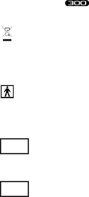
Symbol on the equipment and in the users’ instructions.
Symbol for the separate disposal of electrical and electronic equipment, in
accordance with Directive 2002/96/CE (WEEE).
e equipment belongs to Group 8 (medical equipment).
In force in the nations of the European Union, Norway and Switzerland.
Symbol on the equipment:
e gure in the square indicates the insulation class and the part types
used. In accordance with Standard ISO 60601-1, the equipment has an
internal power supply and the parts used are type BF.
REF
Symbol on the equipment:
Symbol located next to the model number (ref. to catalogue).
SN
Symbol on the equipment:
Symbol located next to the series number on the equipment.

7
BTS
Bioengineering
BTS FREEEMG
icons, symbols and acronyms
Symbol on the equipment:
CE mark with the code of the Notied Body. e CE mark certies that
the product conforms to the standards applicable in the member states of
the European Union (see Declaration of Conformity).
Symbol on the equipment:
CE mark with the code of the Notied Body. e CE mark certies
that the product conforms to the Directive 99/05/EEC - R&TTE and
obtained the Expert Opinion by IMQ.
Symbol on the equipment:
e double square indicates that the product is a medical device of II
Class (In accordance with the law EN 60601-1).
Symbol on the equipment:
e “FCC” symbol refers to the Federal Communication Commission of
the USA. e device complies with the relevant regulations put forth by
the FCC as long as it is operated according to the instructions contained
in this manual and to all national and local regulations.

8
BTS
Bioengineering
BTS FREEEMG
icons, symbols and acronyms
Symbol on the equipment:
e symbol indicates that U.S. Federal law restricts this device to sale by or on
the order of a licensed healthcare practitioner.
Acronyms used in this manual:
AP Access Point PDA Personal Digital Assistant
AU Acquisition Unit RU Receiving Unit
EMG Electromyography SW Workstation
FSW Footswitch

9
BTS
Bioengineering
BTS FREEEMG
Radio equipment identication:
- EMG probes:
FCC ID: YQH-BTSWEMG2
IC: 9188A-BTSWEMG2
- FSWEGN probes:
FCC ID: YQH-BTSWAUX
IC: 9188A-BTSWAUX
- Acquisition Unit contains:
FCC ID: TFB-MATRIXLP
IC: 5969A-MATRIXLP
is device complies with part 15 of the FCC Rules. Operation is subject
to the following two conditions: (1) is device may not cause harmful
interference, and (2) this device must accept any interference received,
including interference that may cause undesired operation.
Modications not expressly approved by BTS SpA could void the
user’s authority to operate the equipment under FCC rules.
radio regulation
10
BTS
Bioengineering
BTS FREEEMG
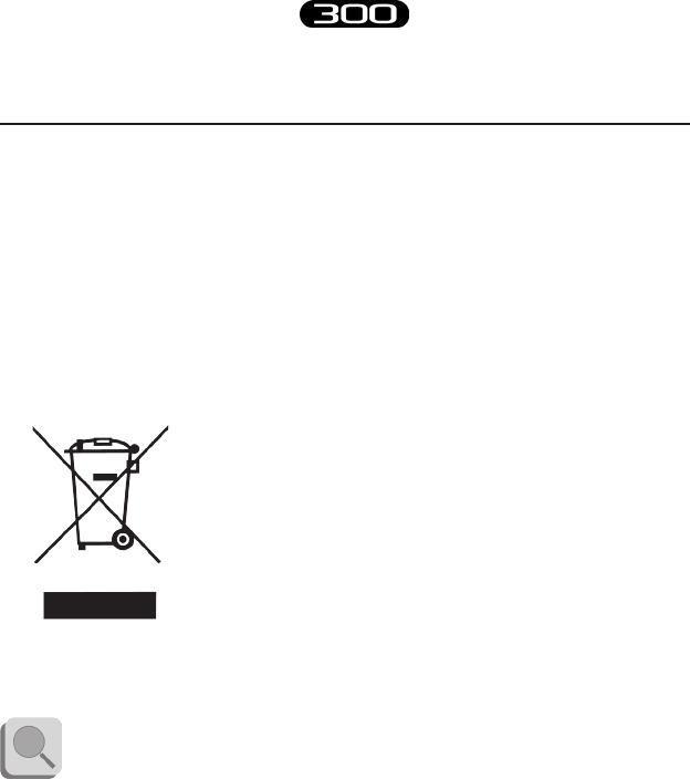
In disposing of the equipment observe the legal prescriptions.
In accordance with Directive 2002/96/CE (WEEE) all equipment supplied
after 13/08/2005 may not be disposed of in general domestic waste. is
equipment belongs to Category 8 (medical equipment) and is classied in
the Business-to-Business sector.
e symbol of the crossed out rubbish bin
indicates that the equipment must not be
disposed of in normal domestic waste.
e regulations for disposal may dier between
individual countries in the EU. In cases of doubt,
refer to the respective sales outlet.
is is a battery-powered equipment.
See Appendix D for information about the batteries used. Operate
and dispose of this equipment according to the instructions set in
the “warnings” section.
disposal (WEEE)

11
BTS
Bioengineering
BTS FREEEMG
is equipment is an instrument for the EMG surface analysis, classied
as medical equipment in accordance with European Directive 93/42/CE
(and its amendments).
e BTS FREEEMG 300 must always be used only for this purpose, by
qualied persons, in an environment suitable for the execution of EMG
analyses and respecting the prevailing regulations in the countries in which
it is being utilized.
U.S. Federal law restricts this device to sale by or on the order of
a licensed healthcare practitioner.
intended use
12
BTS
Bioengineering
BTS FREEEMG
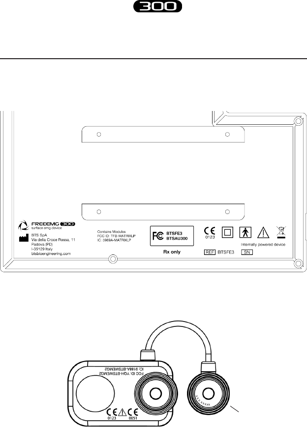
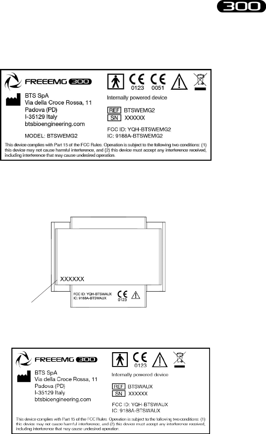
Acquisition Unit Regulatory label
EMG Wireless Probes Regulatory label
Label on the probes:
regulatory label
Probe ID
13
BTS
Bioengineering
BTS FREEEMG
regulatory label
Label not on actual probes due to size constraints:
AUX Wireless Probes Regulatory label
Label on the probes:
Label not on actual probes due to size constraints:
Probe ID
14
BTS
Bioengineering
BTS FREEEMG
regulatory label
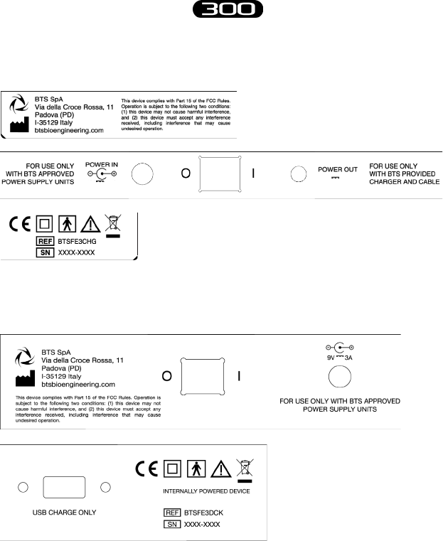
BTS Charger Regulatory label
BTS Docking Station Regulatory label
3A
3A 9V
3A 9V
15
BTS
Bioengineering
BTS FREEEMG
We recommend to carry out any kind of operation keeping
strictly to the security regulations contained in this manual. e
safety of the instrument cannot be guaranteed if these conditions
are not respected.
BTS FreeEMG 300 is a medical device (EU Directive 93/42/CE and its
amendments, including Directive 2007/47/CE) which use must be at all
times be supervised by qualied and authorized personnel, according to
the laws in force in the nation it is in use. e EMG probes are classied as
ETSI EN 300 440 “Receiver category 3” according to Directive R&TTE
99/5/EEC.
e results of the acquisitions must be assessed by people legally authorised
by national law, who possess the suitable necessary knowledge of anatomy
and muscular function.
e instrument must be used in a medical environment, since it has a high
level of sensitivity (measured voltage levels of between 1 microvolt and 6
millivolt).
e uses of the device for other purposes and with methodologies
dierent from of those indicated in this manual are not to be
considered congruent with the precise use of the device.
During the preparation of the patient, take particular care that the system’s
components do not impede in any way the normal movements of the
subject. Apply the probes only on undamaged skin.
warnings

16
BTS
Bioengineering
BTS FREEEMG
warnings
• Only use CE branded probes and hypoallergenic double-sided tape,
compatible with the usage on undamaged skin for brief periods of time.
• Periodically verify the integrity of the system and of its components.
• To not wet or dip in water the parts that make up the system.
No modication of this equipment is allowed.
• Only BTS S.p.A. authorized technicians may maintain and operate
servicing to the instrument. BTS S.p.A. cannot be held responsible
for system safety should the instrument be opened, repairs carried out,
third parties software be installed, or system components be replaced by
persons other than those authorized by BTS S.p.A.
• Users cannot change any software conguration (including O.S. and
CD writer software).
• In case the device accidentally falls, tear of the probes or other accidents
always address authorized technical support.
• Use only the provided power supply unit FW7363M/09 (FRIWO)
or the one provided by BTS S.p.A. for supplying docking station and
charger unit. If a dierent power supply unit is used, the compliance to
IEC 60601-1 is not ensured.
• Only original cables must be used, otherwise BTS S.p.A. cannot assure
the safety of the instrument. Should it be necessary to replace any part
of the system, only original BTS S.p.A. parts may be used.
In addition to the users’ instructions, the prescriptions regarding
accident prevention and technical regulations regarding
occupational safety must also be complied with. e appertaining
national regulations and standards of the country of use, with
regards prevention of accidents and environment, are an extension
of the users’ instructions.

17
BTS
Bioengineering
BTS FREEEMG
warnings
• Make sure that the cables have been connected correctly. When
disconnecting cables, use the connectors and not the cables themselves
to unplug the connectors.
• Mains plug of external power supply unit is considered as disconnecting
device.
• Avoid connecting the probes to the charger with inverted polarity with
respect to that shown on the cover of the recharger – is could cause
irreparable damage to them.
• For a safe use and adequate maintenance of rechargeable batteries strictly
follow the instructions given in this manual. If rechargeable batteries
are used in such a way that is not the one specied by BTS S.p.A. the
shelf life, functionality and the integrity of the batteries is not ensured.
• ESD application to EGN probes, causes a loss of link to the device.
Temporary loss of function or performance which is recoverable with
operator action.
BTS FREEEMG 300 is a device that is able to function
COUNTINUOUSLY, this is of course limited by the battery
duration and by the memory available for the acquisition data
storing.
e device uses lithium ion battery. For the battery replacement
and disposal please contact the technical support. At any rate,
ensure that device component (i.e.) probes, receiving unit, …)
integrity is never compromised.
e information contained in this manual is subject to change
without notice and does not constitute product specications or
any obligation on the part of BTS S.p.A.
18
BTS
Bioengineering
BTS FREEEMG
e software of the system described in this manual is supplied with the
“licence to use” contract. e software may be used or copied only as
stipulated under the terms of this contract.
No part of this manual may be copied or transmitted in any form or means,
electronic or mechanical, including photocopying, without prior written
permission from BTS S.p.A.
Unless otherwise specied, any reference to companies, names, data and
addresses used in the reproduction of the screens and the examples are
purely incidental, and has the sole purpose of illustrating the use of the
BTS product. All trademarks are registered by the respective owners.
is publication contains reserved information which is the
property of BTS S.p.A.
e recipient acknowledges that the illustrations and information
supplied in this manual shall not be made available to third parties
without explicit written agreement by BTS S.p.A.
copyright

19
BTS
Bioengineering
BTS FREEEMG
General description
BTS FREEEMG 300 is an indispensable instrument for laboratories
which are concerned with the study of muscular activity in the elds
of rehabilitation, sports medicine, ergonomics, clinical research, and
assessment of functional ability and muscular fatigue.
BTS FREEEMG 300 makes the selection of muscles, the setting of
duration and frequency of acquisition, amplication gain and the correct
positioning of electrodes, simple and rapid.
BTS FREEEMG 300 can be applied in research, sports, occupational
medicine, gnatology, neurology, and orthopaedics.
With the software tools available, BTS FREEEMG 300 becomes an
advanced diagnostic tool to evaluate neurological and orthopaedic
disorders, pharmacological therapy, progression of motor decits, use
of ortheses, rehabilitative follow-up, and to optimize sports training
programmes,...
BTS FREEEMG 300 is applied with EMG-Analyzer the most complete
software solution for analyzing electromyographic signals. It includes
predened templates for evaluations in the clinical, sports, and research
eld: Jump, plyometrics, walking, fatigue analysis, isokinetic, etc...
BTS EMG-Analyzer also has an editor for creating elaboration protocols:
introduction
20
BTS
Bioengineering
BTS FREEEMG
introduction
thanks to an innovative object interface, that translates the biomechanical
analysis language into graphical form, the user can develop quickly and
eectively customized analysis protocols.
BTS FREEEMG 300 seamlessly integrates with BTS motion analysis
systems, through the SMART (and ELITE) dedicated software.
Case contents
Standard components:
• Receiving Unit
• Acquisition Unit
• HP iPAQ hx4700 Pocket PC
• Belts for attachment to patient
• Stylus (located in the Pocket PC)
• Probes Kit
• up to 16 wireless probes (identicative labels available in 4
dierent colors)
Acquisition Unit
Pocket PC
21
BTS
Bioengineering
BTS FREEEMG
introduction
• Probes Chargers:
• up to 2 “Charger” units:
each charger handles up
to 8 probes and 2 FSW/
EGN.
e second unit is included in the
standard kit only for FREEEMG with at least 12 probes, or
available as an option.
• e optional “Docking Station” version is also available
• Accessories
• USB-PDA cable •AC adapter
• Access Point
• Set of disposable electrodes
22
BTS
Bioengineering
BTS FREEEMG
introduction
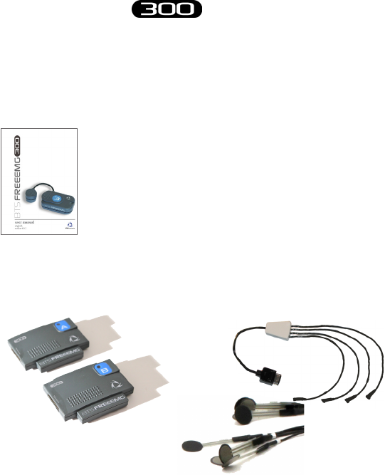
• Manuals
• BTS FREEEMG 300 user
manual complete of CD
Optional components:
• Footswitch Kit
• 2 FSW/EGN Wireless Probes • 2 Connectors of 4 Switches
• 10 single Switches
• Fine-Wire Adaptor
• Fine-Wire Kit
• xing set for Fine-Wire adaptor
• set of disposal Fine-Wire electrodes with applicator
• Electrogoniometer Kit
23
BTS
Bioengineering
BTS FREEEMG
introduction
• 1 FSW/EGN Wireless Probe • 1 Electrogoniometer
• 1 Connector
• Supplementary Receiving Unit
• Secure Digital
You will receive the instructions for use for other possible op-
tional components not mentioned in this manual.
24
BTS
Bioengineering
BTS FREEEMG
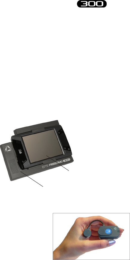
BTS FREEEMG 300 electromyograph consists of a receiving unit which
utilizes a PocketPC platform and wireless probes designed and developed
by BTS SpA.
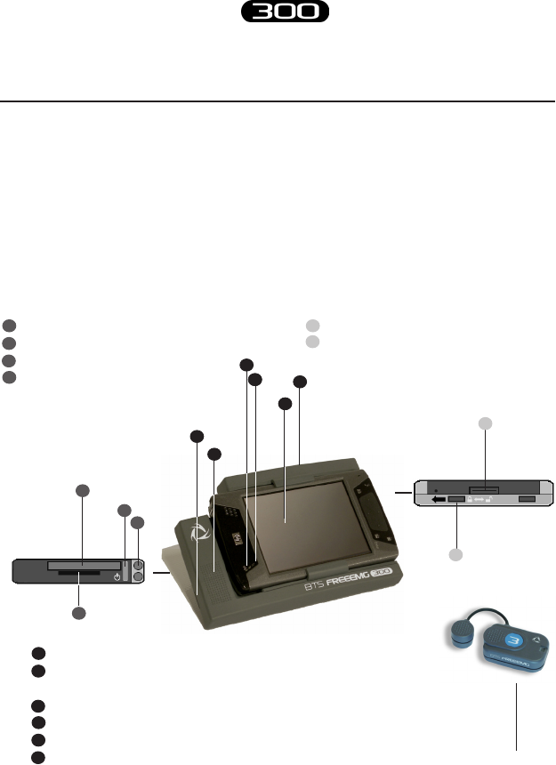
Physical description
activesync connector
battery door lock (in lock position to
switch on BTS FREEEMG 300)
1
2
power button (on/o)
Compact Flash (CF) slot type II
Secure Digital (SD) slot
stylus pen
1
2
3
4
1
2
3
4
5
6wireless probes
system components
LED - WIFI (solid blue = WiFi Active)
LED - charging and notication indicators
(blinking amber = charging; solid amber = full charge)
VGA color display
antenna
service slot
grip
1
2
2
5
2
4
3
1
2
1
3
4
6
25
BTS
Bioengineering
BTS FREEEMG
system components
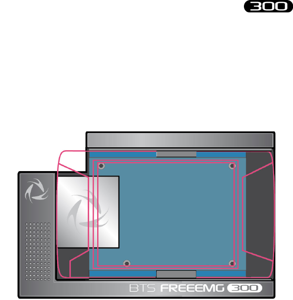
Acquisition unit
e acquisition unit consists of:
• a digital card
• a receiver card
• a plastic casing
• a guide for the PDA insertion.
e digital card is connected to the palmtop, via the Compact Flash port,
when this is made to slide in the proper guide.
When the acquisition unit is connected to the palmtop, the card
communicates, “describing” itself to the driver in operation and thereby
allowing the system to self-congure and to carry out a self-diagnosis.
In addition to serving as a Compact Flash interface the card allows control

26
BTS
Bioengineering
BTS FREEEMG
system components
of the receiver card and handles acquisition of data coming from the
probes.
e receiver card is comprised of 4 elements that act as coordinators
of the wireless connection network with the probes, thus managing
communications with the probes, both for activation and data acquisition.
e acquisition unit is able to handle:
• up to 16 probes, used for acquisition of the activity of the same
number of electromyographic signals
• up to 2 probes of 4 auxiliary channels for switch connection,
used for the basographic acquisition
• as an alternative to the EMG channels it is possible to acquire
up to 8 electrogoniometers (each EGN occupies 2 analogue
channels).
In particular, the following probe combinations are possible:
EGN EMG FSW
0 up to 16 probes 2 probes of 4 switches
1-2 up to 12 probes 2 probes of 4 switches
3-4 up to 8 probes 2 probes of 4 switches
5-6 up to 4 probes 1 probe of 4 switches
7-8 0 0
27
BTS
Bioengineering
BTS FREEEMG
system components
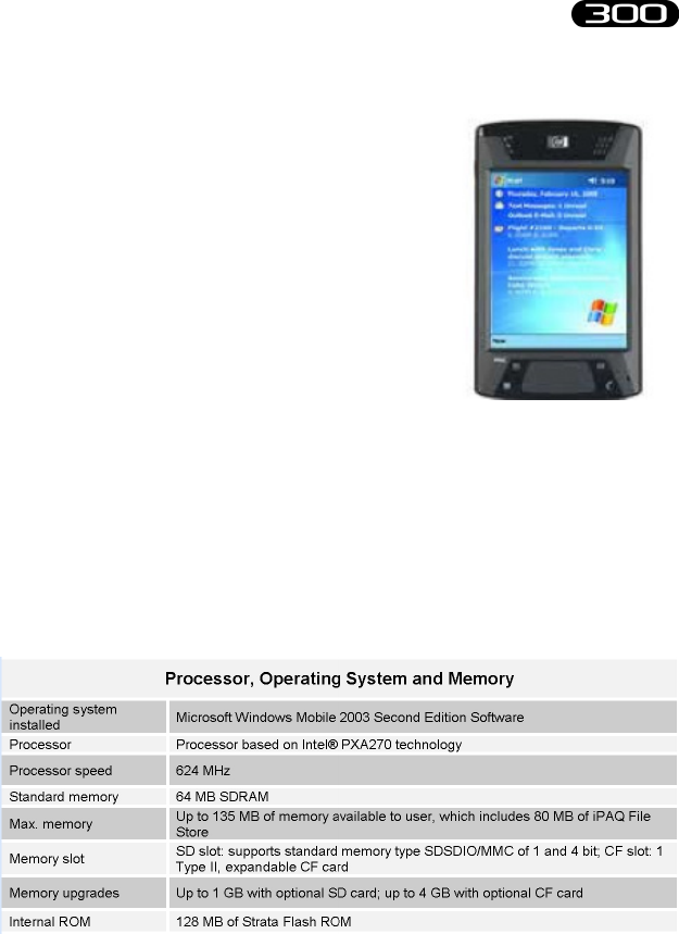
PDA (Personal Digital Assistant)
HP iPAQ hx4700 Pocket PC is based on
Microsoft® Windows®.
It uses the Intel® PXA270 processor and
the new transective display VGATFT, 4”
with 64k colors, to provide exceptional
graphics power and performance to display
large dimension images at highest quality
resolution.
HP hx4700 is tted with excellent expansion capacity (Compact Flash
Type II and SD slot) to provide more storage space and greater function
range.
64 MB of SDRAM and 128 MB of ROM memory allow a greater number
of programmes and les to be stored, while the 1800 mAh lithium ion
battery ensures longer uninterrupted use of the Pocket PC.
28
BTS
Bioengineering
BTS FREEEMG
system components
For further details please refer to the HP iPAQ hx4700 Pocket PC
Manual included.
29
BTS
Bioengineering
BTS FREEEMG
system components
Wireless EMG Probes
BTS FREEEMG 300 utilizes miniaturized probes with active electrodes
weighing less than 13 grams. e special design ensures maximum space-
saving and comfort for the patient who is free to move around without
obstacles.
e probes can be hooked on directly to the pre-gelled electrodes without
requiring additional xing with plasters or double-sided tape. is together
with the total absence of cables enables a much faster patient preparation,
drastically reducing the time of each session.
Each receiving unit can control up to 16 probes, for a total therefore of
16 analysable muscles in a single exam (standard conguration with one
receiving unit).
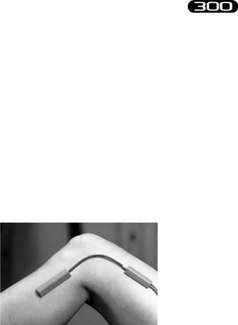
Each probe consists of a mother electrode and a satellite electrode, each
tted with a clip. e two parts, connected via a exible cable, may be
positioned as needed by the user at adjustable distance (electrodes with
variable geometry).
In the mother electrode there are the A/D converter, the antenna and
the battery. In the satellite electrode there is the Signal Conditioning
(preamplier and lter) and is reported the probe ID.
All probes are also equipped with a solid state memory buer, to prevent
data loss for problems due to the Wi-Fi network or due to exceeding the
useful operating range.
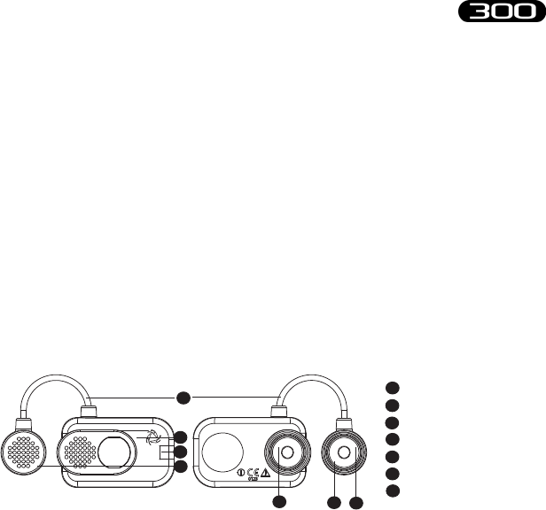
1
2
3
4
5
mother electrode
LED
satellite electrode
mother electrode clip
satellite electrode clip
exible cable
probe ID
6
7
5
1
2
2
5
3
4
6
7

30
BTS
Bioengineering
BTS FREEEMG
system components
Each probe is tted with an LED indicating its state. e probes can be in
one of a number of dierent states:
• Charge: steady blue LED.
During the recharging phase the steady blue LED is on.
is phase occurs when the probes are connected to the charger
turned on, and the charge level is less than 90%.
When the charge level reaches 90% the led turns OFF.
Since, by connecting a probe to the charger on, it enters in “Deep
Sleep” mode, even while charging, the probe will be completely
passive and does not respond to any commands.
• Inactive: white LED which cyclically lights with a steady light
for a few seconds every 3 minutes.
In the “Inactive” mode the probes cannot be used directly by the
patient unit but are in constant standby to be activated by the
activation software. When the probe is inactive, it carries out a
scan of the radio frequencies: during the scan the white LED is
lit continuously.
• Active-Scanning: white LED which cyclically lights for a few
seconds.
In this mode the probe is searching for the receiving unit on
the channel assigned during the activation phase. At intervals of
about 1 minutes it carries out a scan of the frequencies of few
seconds. During the scan the white LED ashes quickly.
• Active-Connected: white LED which ashes slowly.
When the probe and the receiving unit establish a connection,
the white LED begins to pulse slowly: the probe is waiting for

31
BTS
Bioengineering
BTS FREEEMG
system components
commands. If the connection is interrupted, the probe returns
to “Active-Scanning” mode and attempts to re-establish the
connection.
• Active-Capturing: white LED which lights and goes out at
regular intervals.
During acquisition the white LED ashes at regular intervals of
approximately one second. At the conclusion of the acquisition,
the probe returns to the “Active-Connected” condition. If
during the acquisition, connection to the receiver unit is lost,
the probe continues to acquire, storing the data locally for one
minute and at the same time scans the assigned channel trying
to reconnect to the receiving unit. If after one minute the scan
is unsuccessful, the probe returns to the “Active-Scanning”
condition interrupting the storage of data.
• Completely discharged or in “Deep Sleep” mode: LED is o.
If the probe is completely discharged the LED does not display
any ashing cycle and is o. e same happens when it is in
“Deep Sleep” mode (except during the recharging phase in
witch the led is steady blue).
e probes in “Deep Sleep” mode do not perform any
scan cycle, but are turned o. Is therefore guaranteed
energy savings.
To put the probe in “Deep Sleep” mode it is necessary to connect
them to the Charger switched on, or to put them in contact
with a magnet for half a second.
32
BTS
Bioengineering
BTS FREEEMG
system components
Before the next use is necessary to reactivate the
probes, putting them in contact with a magnet. After
this operation they will pass to “Inactive” mode.
e probes are charged by a dedicated charger to which the probes are
connected via their respective clips.
When the probes are in charge and the charger is turned on, they
are in “Deep Sleep” mode and all the LEDs are o. it is necessary
to reactivate the probes, prior to use them, using a magnet.
e EMG probes can be used also to acquire the EMG signal by means of
Fine-Wire electrodes.
With this aim, there are available, in option, adaptors allowing for the
connection with Fine-Wire electrodes. e EMG probes can be connected
to them using the clips. Each adaptor can be xed to the subject by means
of proper elastics.
For these applications the acquisition frequency must be set on
4 KHz (the guidelines recommend for Fine-Wire electrodes an
acquisition frequency major or equal to 2 KHz).
33
BTS
Bioengineering
BTS FREEEMG
system components
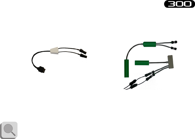
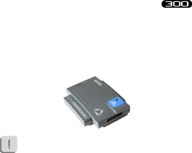
Wireless FSW/EGN Probes (optional)
For collecting the on-o analysis signals coming from the Footswitch
or for collecting data from the Electrogoniometers (optional system
components) BTS FREEEMG 300 uses wireless probes which must be
connected to the FSW or EGN probes using a special connector.
e probe will work dierently if used with one or the other
probe and will receive from the same receiving unit information
on its work modality during activation.
e probe consists of a single parallelepiped-shaped block.
e upper face has an ID tag characterized by a color (Green, Red, Yellow,
Blue) and a letter (A, B, C, D, E or F) and a status LED which operates
similar to that described for the EMG probes (see previous paragraph).
e two lateral faces have two connectors; the one on the ID tag side
serves to charge the probe, and a cable will be connected to this to enable
connection to the charger (Charger or Docking Station).
e one on the other side is for the probe connections (FSW or EGN).
Finally, the ID identier of the probe is on the bottom left corner of the
back side.
34
BTS
Bioengineering
BTS FREEEMG
system components
On-o analysis (optional)
e footswitches are useful in dening the contact points during the
contact phases of deambulation.
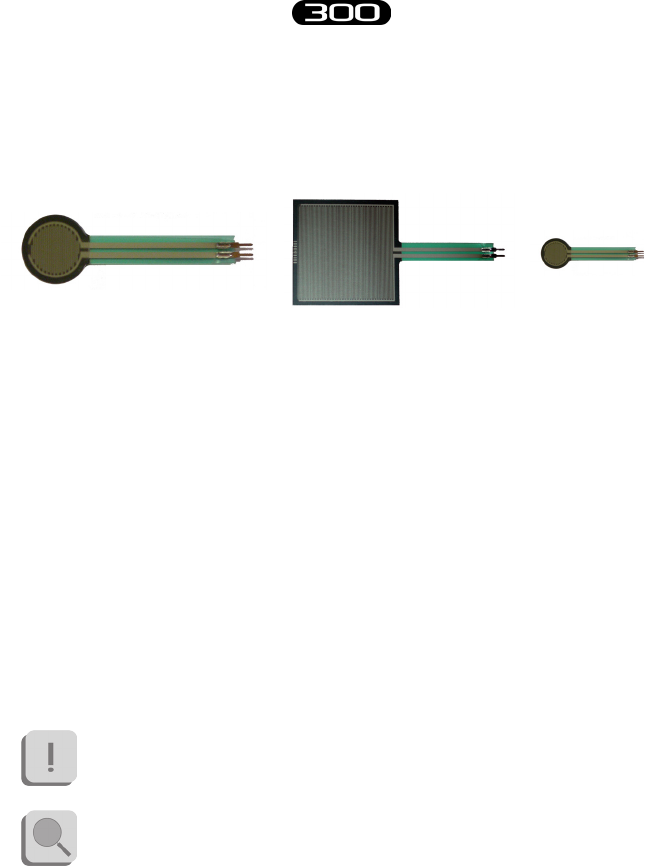
e footswitches consist of a resistive membrane, (FSR technology), of
diameter 18 mm and thickness less than 0.5 mm, expressly designed for
applications in the analysis of movement.
e compact size of the instrument permits a maximum of exibility in
positioning on the patient’s foot.
For applications other than gait analysis, there are available on request
smaller diameter (8 mm) switch probes (appliable, for example, to the
nger), and square (useful for tapping tests), 44 mm x 44 mm.
BTS FREEEMG 300 permits up to 8 basographic zones to be measured,
through 2 connectors from 4 single switches (usually right and left side)
that are connected to the two FSW/EGN wireless probes.
e footswitch channels are supplementary to the 16
electromyographic channels.
Refer to § “Acquisition unit” for the list of probe combinations
possible in case of acquisition also with EGN.
35
BTS
Bioengineering
BTS FREEEMG
system components
Electrogoniometers (optional)
e electrogoniometer is an easy to use device that allows the measurement
of joint angle progress over time.
ere are primarily two types of electrogoniometers: the potentiometer
and the strain gauge. BTS FREEEMG 300 uses the strain gauge
electrogoniometer of Biometrics LTD.
ere are single-axle models for the neck (axial rotation) and the forearm
(prone-supination) and biaxial models for other main joints: wrist, elbow,
knee, ankle, hip and back.
e strain gauge electrogoniometers are made up of two sensors, connected
to each other, that are xed to the bone segments involved in the joint to
value.
e measure of the angle is provided by the relative angle between the
axes of the two sensors and, unlike the potentiometric electrogoniometers,
it doesn’t depend on the linear slidings in which the two extremities can
incur.
Each electrogoniometer is connected to a FSW/EGN wireless probe
using the appropriate connector. Each receiving unit can handle up to 8
electrogoniometers.
36
BTS
Bioengineering
BTS FREEEMG
system components
e electrogoniometer channels are not supplementary to the 16
electromyographic channels, but each electrogoniometer used
engages 2 EMG channels. Refer to § “Acquisition unit” for the
detailed list of probe combinations possible.
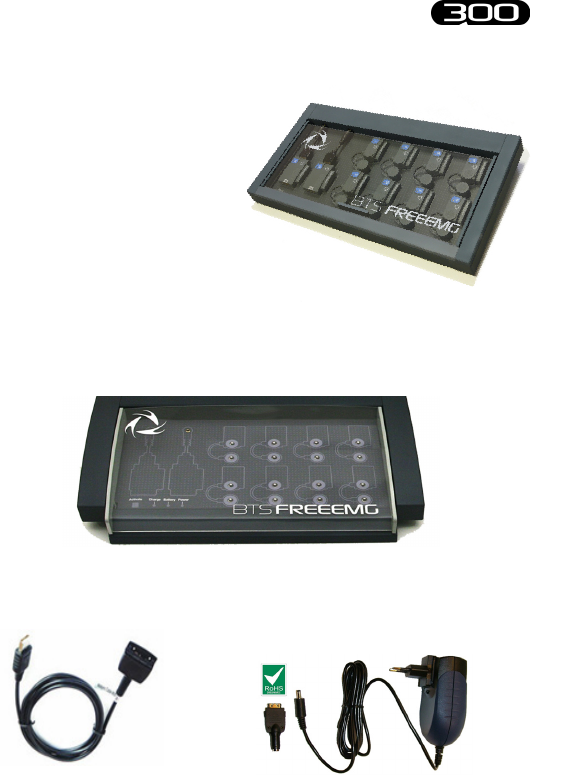
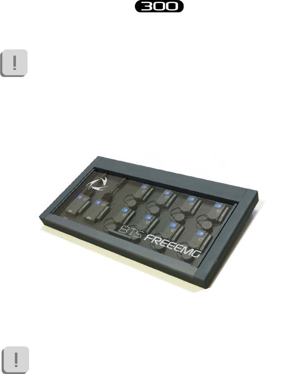
Charger
e Charger, included with the product, charges the FREEEMG probes.
e Charger can simultaneously charge 8 EMG probes and 2 FSW/EGN
probes.
Two units are provided for systems with more than 12 probes.
More units can be connected in series for simultaneous power
supply through the same AC adapter, using the cable included.
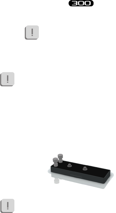
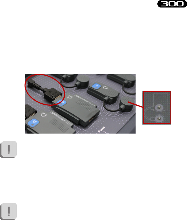
e EMG probes are connected to the charger using the same clips that
normally collect the EMG signal, while the FSW/EGN probes connect to
the charger using the special connector as shown in the gure below:
37
BTS
Bioengineering
BTS FREEEMG
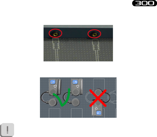
system components
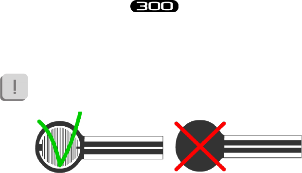
For correct connection simply follow the outline of the probes shown on
the base of the Charger:
e Charger comes with an output short circuit protection
system also in case of reversed recharging poles. At any rate, poles
connected incorrectly will not recharge.
To recharge connect all the probes that you would like to charge to the
Charger (follow the instructions described above) and connect the AC/
DC adaptor to the mains and turn on the switch located on the rear panel.
When the Charger is properly connected to the mains and has been turned
on, the status LED “Power” will show a steady GREEN light.
e charging status of the EMG probes and of the FSW/EGN probes is
indicated by the respective status LED (see § “Wireless EMG Probes” and
“Wireless FSW/EGN Probes”).
38
BTS
Bioengineering
BTS FREEEMG
system components
Note that inserting the EMG probes into the Charger when it is
on, these come in “Deep Sleep” mode. It is necessary to reactivate
these probes, prior to use them, using a magnet. After this
operation they will pass to “Inactive” mode. While, connecting
the FSW/EGN probes to the Charger (connected to the mains
and turned on) if they are charged less than 90% they will be
automatically reset and will pass to the “Inactive” mode.
To proceed with another acquisitions it is necessary to repeat the
activation procedure.
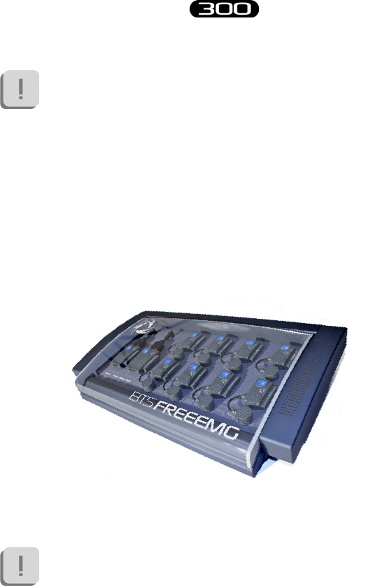
Docking Station (optional)
As in alternative to the Charger an optional Docking Station is available.
is unit has additional features that are described below.
Each Docking Station can simultaneously charge 8 EMG probes and 2
FSW/EGN probes.
Unlike the standard Charger, each Docking Station will have to
be powered separately; therefore two units cannot be connected in
series for contemporary power supply.
39
BTS
Bioengineering
BTS FREEEMG
system components
e EMG probes are connected to the charger using the clips for collecting
the electromyographic signal, while the FSW/EGN probes connect to the
charger using the special connector.
For correct positioning simply follow the outline shown on the base of the
Docking Station as shown in the following gure:
e Docking Station comes with an output short circuit protection
system also in case of reversed recharging poles.
At any rate, poles connected incorrectly will not recharge.
e Docking Station also allows for recharging the receiving unit by
connecting it with the relevant cable (USB/PDA cable) in the USB port
located on the rear panel.
It should be noted that you can use the Docking Station to
recharge the PDA only when by pressing the power button the
palmtop turns on.
Otherwise you will need to recharge the PDA with the supplied
HP by connecting it to the network. In order to go back and
recharge using the Docking Station, simply charge with the
power supply unit for about one minute, and then check that it is
40
BTS
Bioengineering
BTS FREEEMG
system components
suciently charged by unplugging it from the power supply unit
and turning it o and then back on.
ere are two ways to recharge the probes:
• using the medical power supply unit from the network
• using the internal battery
e rst method involves the connection of the Docking Station by means
of the AC/DC adaptor to the mains. In this case not only the connected
probes will be charged but also the internal battery of the unit itself.
e second method lets you recharge the probes and/or the receiving
unit when you are not at the laboratory and a mains power network is
unavailable. In particular with the battery fully charged you can fully
recharge all the probes and receiving unit or fully charge the probes only
twice.
To recharge a probe simply connect it as described in the method above.
Connection to the Docking Station resets the probe if charged
less than 90%, to use it again for acquisitions you must repeat the
activation procedure.
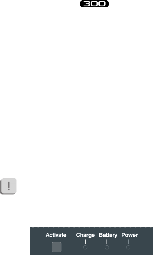
e Docking System is equipped with an “Activate” button and 3 status
LEDs: “Charge”, “Battery” and “Power”.

41
BTS
Bioengineering
BTS FREEEMG
system components
e “Activate” button allows immediate activation of the FSW/EGN
probes connected to the Docking Station and selected to activate in the
receiving unit (see § “Active” Button); you do not need to wait for the
software cycle of the “inactive” state probe to be complete. By pressing the
button the FSW/EGN probe will immediately scan the radio frequencies
and enter immediately in communication with the receiving unit.
e “Charge” LED gives information on the probes charging and consists
of a BLUE light which signals the following:
• BLUE LED “breathing”: indicates that the probes are charging.
Two situations can be veried in this case:
• Status LED of the probe on: e probe is charged less
than 90%
• Status LED of the probe o: e probe is more than
90% charged but still not complete.
It is important to remember that the LED of
the probe stays on until it is 90% charged. is
function allows you to have an indication on
the full charge of the probe, therefore increasing
the autonomy of the probe by about 10%.
• BLUE LED o: indicates that all probes are fully recharged.
• BLUE LED x on: indicates that the “activate” button has been
pressed. In this case the probes are not powered by the Docking
Station but by the probe’s battery.
e “Battery” LED is an indicator of the state of the auxiliary battery
and consists of a two-tone RED- GREEN LED, whose signals have the

42
BTS
Bioengineering
BTS FREEEMG
system components
following signicance:
• LED o (both the RED light and the GREEN light are o): in
this case the battery is in sleep mode or has been removed from
the Docking Station
• GREEN light of LED on: the auxiliary battery is charging.
• Steady RED light of LED on: the auxiliary battery is fully
charged.
• Blinking RED light of LED on: indicates battery malfunction
or a battery charging problem.
e “Power” LED is on (GREEN light) when the switch located on the
rear panel of the Docking Station is ON and it is connected to the mains
or, if this is not the case, the auxiliary battery is suciently charged.
e Docking Station has a lid, which opens automatically by means of
a spring- brake mechanism, which works by pressing close to the word
“Push”, located on the left shoulder of the unit.
e probes should be put back in the Docking Station when not
in use for acquisition sessions. Moreover, if left for a long period,
we recommend turning of the unit by moving the switch located
on the rear panel of the Docking Station to OFF. Close the lid for
better protection of the probes.

43
BTS
Bioengineering
BTS FREEEMG
User PC minimum conguration
Operating system Windows XP
Microsoft.NET framework 1.1
Processor P IV 1600 MHz
RAM 256 MB
Video card 32 MB, Open GL
Disk space 100 MB for the application,
not including storage for acquired data
USB 2.0
Installation of the Wi-Fi Interface
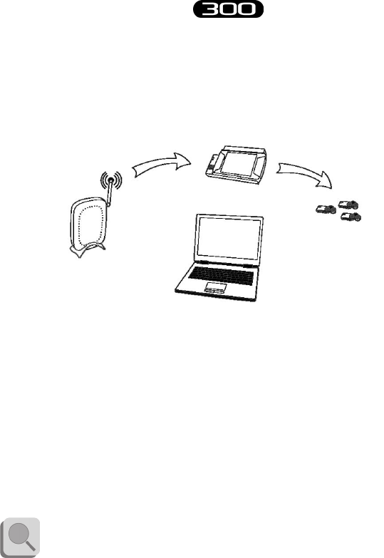
e real time data transmission between the BTS FREEEMG 300 and the
Workstation occurs thanks to the Wi-Fi network. is type of connection
is permitted using an Access Point supplied with the system.
An AP is an Ethernet device which works with devices present in a small
area.
e AP, starting point of the service, operates from bridges between the
wireless devices and the systems physically connected to the network with
an RJ45 connector.
e AP transmits the signals to the surrounding area via radio waves. All
the wireless devices within the area can receive signals and communicate
with the AP, and through them, with all the other devices, creating a
network without cables.
installation
44
BTS
Bioengineering
BTS FREEEMG
installation
Connecting a Workstation (PC laptop or desktop), not provided with a
Wi-Fi interface, to Access Point with a normal network cable is created
through the wireless connection with BTS FREEEMG 300.
e access point included in the system is already congured with the
network name (SSID) “BTSFREEEMG300” with transmission on
channel 6. e base conguration prepared in BTS (factory settings) uses
the following IP addresses:
Access Point 192.168.1.1
BTS FREEEMG 300 192.168.1.2
Workstation assigned automatically
by the Access Point
You should always use the AP included even if the Workstation is
equipped with a Wi-Fi interface.
Receiving Unit
Workstation
Access Point
Wireless Probes

45
BTS
Bioengineering
BTS FREEEMG
installation
Description of the software on the user PC
BTS EMG-Analyzer is the complete and highly exible solution for
making advanced elaborations of electromyographic signals and angular
measurements of body segments.
Includes predened templates for evaluations in clinics, sports, and
research and an editor to develop customized elaboration protocols.
However BTS FREEEMG 300 is manageable by all BTS applications of
SMART family dedicated to the motion analysis with which is possible
to acquire and process the electromyography signals in a integrate and
synchronous way with the other devices connected.
e SMART-Analyzer software allows to perform advanced elaborations
of the EMG signals, integrating the electromyography information with
the cinematic and kinetic data.
It is possible to construct customized analysis protocols complete of
advanced multimedial report.
Switching on BTS FREEEMG 300
e patients unit consists of two main components: the PDA and the
Acquisition Unit and is usually given with the two parts already connected.
Anyway, to connect the Acquisition Unit to the palmtop, run the PDA
along the AU guides, being particularly careful that the CF enters the
For more details concerning the use of this software, please refer
to its specic manual.
46
BTS
Bioengineering
BTS FREEEMG
installation
appropriate slot without being forced or receives any sudden impact, and
avoid any excessive pressure on the palmtop screen.
To avoid damaging the Compact Flash we suggest only to remove
the PDA from the AU only if necessary and in any case, even if
expressly requested, it is suggested not to move it completely from
its place, but to let it slip just enough to disconnect it from the
digital card (more or less 1 cm) event that will be signalled by an
audio beep.
e recharge of the battery and the transfer of data with the USB
can also be done through the specic cable, without disconnecting
the AU or the PDA.
It is also advisable to perform a connecting/separating operation
of these parts only when the device is turned o.
Check the connection between PDA and AU.
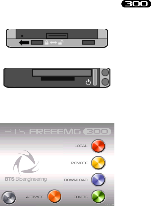
Switch on the BTS FREEEMG 300: check that the slot switch, located
on the side of the BTS FREEEMG 300 shown in the diagram, is in the
position closest to the closed lock symbol. If not, move it to this position.
47
BTS
Bioengineering
BTS FREEEMG
installation
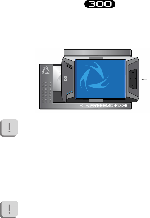
Switch on by actuating the button on the opposite side of the BTS
FREEEMG 300, as shown here:
At this point wait until the application BTS FREEEMG 300 is completely
charged. On the BTS FREEEMG 300 display the following screen will be
visualized:
First Connection
e BTS FREEEMG 300 is supplied with the onboard PDA software
preinstalled and congured. In any case for the rst connection we suggest
to perform some verications.
48
BTS
Bioengineering
BTS FREEEMG
installation
Connection check
e user PC communicates with the BTS FREEEMG 300 by means of
Wi-Fi protocol through the Access Point (see § “Installation of the Wi-Fi
Interface”).
Verify that the local net resources are laid out, like assumed in the
conguration of default according to BTS, the PC user IP address must
assigned automatically by the Access Point.
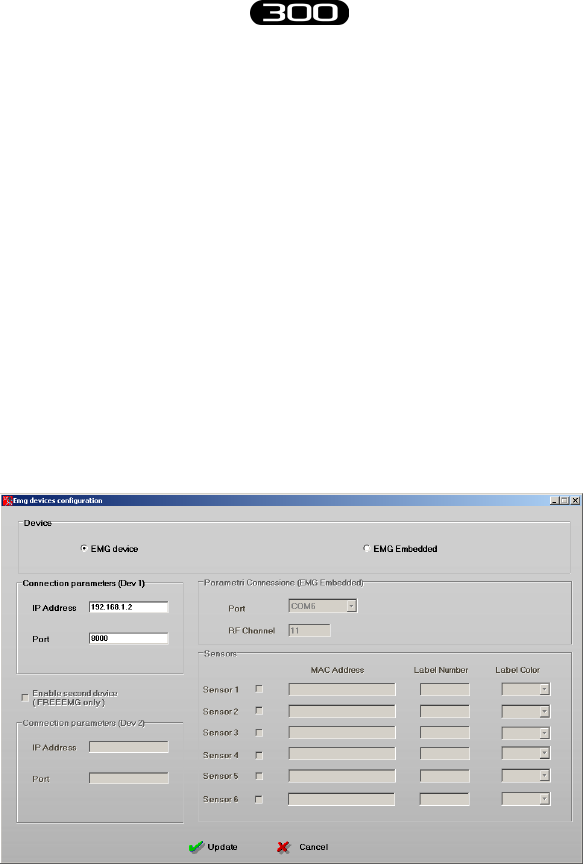
Verify the software conguration installed on the PC.
To do so, launch the program that you want to congure, i.e. EMG-
Analyzer, and on the menu bar at the voice “Laboratory” select “Select
Emg Device” and verify that the check is on the voice “FREEEMG”.
en, again from the menu bar at the voice “Laboratory”, select “Set Emg
Device” and verify that the check is on “EMG device”:
49
BTS
Bioengineering
BTS FREEEMG
installation
Verify that the IP address and the port are set with the following connection
parameters:
IP Address: 192.168.1.2
Port: 8000
Moreover, if there is a second BTS FREEEMG 300 receiving unit available
(mind that in this case it is possible to manage up to 8 channels with each
unit), select the option “Activate Second Unit (only for BTS FREEEMG)”
and check that the IP address and the port for the second device are set up
with the following connection parameters:
IP Address: 192.168.1.3
Port: 9000
If the values do not correspond change them and click on “Update” before
closing the window.
Switch-on the BTS FREEEMG 300 (see § “switching on BTS FREEEMG
300”), wait until the application of the acquisition management is
completely loaded and select the remote application clicking on “Remote”.
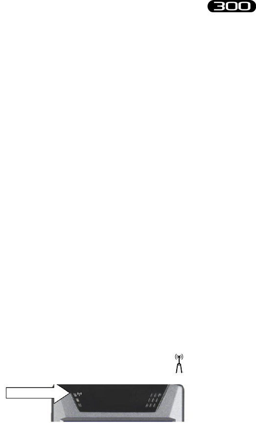
If the Wi-Fi connection between the Receiving Unit and the Workstation
is assigned in the correct way, after clicking on the “Remote” button, the
connection led of the Wi-Fi net, that you can nd on the front of the BTS
FREEEMG 300 and that presents the Wi-Fi logo ( ), will result on
(solid blue).

50
BTS
Bioengineering
BTS FREEEMG
installation
During the start-up of the Remote mode dierent wireless nets
can be found present in the working area.
Always use the “BTSFREEEMG 300” net ignoring the other nets.
From the Workstation launch the BTS EMG-Analyzer application.
Wait until, in the application being used, the respective LED indicating
the state of the Wi-Fi connection between the receiving unit and the
workstation changes from red to ashing green.
Correct data visualization check
During the initial connection, check the correct operation of the probes in
use, and the correct display of data on the BTS FREEEMG 300.
To do this, activate all the EMG probes and, if the system is also provided
with footswitches, two FSW/EGN probes, enabled as FSW, to be tested
all previously charged, as indicated in § ““Active” Button”. When all the
probes are shown to be active on the display, select the Remote mode by
clicking on the “Remote” button. Select the default protocol and then
“Setup Probes” from the menu and wait for all the activated probes to be
acknowledged (the respective box must be green).
To verify the correct functioning of the EMG probes, position a pair of
electrodes (see § “Fitting the Patient”) and connect Probe 1. Next, select
“Gains” from the menu and check the progress of the EMG1 signal.
Repeat the procedure connecting the other probes one at a time.
After checking the electromyograph channels, if the system is also

51
BTS
Bioengineering
BTS FREEEMG
installation
provided with footswitches, attach the connectors with the 4 switches
already inserted to the 2 corresponding FSW/EGN probes. After selecting
from the menu the item “Footswitch” (as shown later in § “Guide to
using the software on the BTS FREEEMG 300”), check each contact is
functioning correctly by pressing rmly each switch and observing the
corresponding red LED light on the display of the BTS FREEEMG 300
(see § “Footswitch”).
If your system has one or more electrogoniometers, repeat the probe
activation procedures deactivating all the EMG probes and enabling
as EGN a number of FSW/EGN probes equal to the number of
electrogoniometers included (maximum 8), refer to § “Active” Button”.
When all the probes required are active go back to Remote mode by
clicking on the “Remote” button. From the Workstation prepare an
acquisition protocol that entails the use of a number of EGN equal to
those provided with your system and transfer it on the receiving unit (see §
“Create a new protocol”). Selection the newly transferred protocol, select
“Probes setup” on the menu and assign each channel to an EGN probe,
checking that they are all recognized (the respective box must be green)
(see § “Probes Setup”).
Finally, connect each electrogoniometer to a connector and then to a
FSW/EGN probe. Select “Gains” from the menu and check the related
signal to the EGN channel that is testing. Repeat the procedure for each
electrogoniometer provided.

52
BTS
Bioengineering
BTS FREEEMG
Now we will describe a basic procedure about how to create a new protocol
using BTS EMG-Analyzer software.
Refer to the EMG-Analyzer manual for further details about the
“Protocol Builder” function.
e procedure may be dierent if performed with other
applications. In this case, refer to the specic manual of the
software you are using.
Please note that with BTS FREEEMG 300 it is possible to acquire:
- up to 16 analog channels: electromyographic signals - EMG (each
EMG employs 1 analog channel), up to 16 electrogoniometer
signals - EGN (each EGN employs 2 analog channels)
- 8 on-o analysis areas - FSW.
Refer to § “Acquisition unit” for the detailed list of possible probe
combinations.
Launch the software EMG-Analyzer and wait for the led of communication
with the receiving unit to be green.
Put BTS FREEEMG 300 in Lab Modality by clicking from the main page
on the “Remote” button; if two receiving units are being used, make sure
that both of them have the Remove Mode activated.
acquisition protocol
53
BTS
Bioengineering
BTS FREEEMG
acquisition protocol
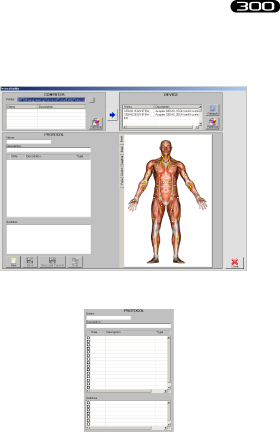
To create a new protocol, from the menu voice “Laboratory” of EMG-
Analyzer, select “Create Emg Protocol” .
A window will open, which allows to create or modify protocols.
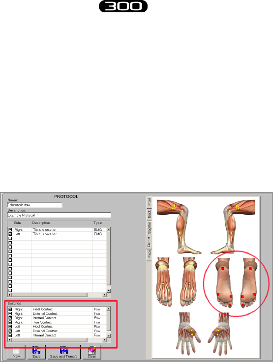
To create a new protocol follow this procedure:
- Click on “New”. e elds to be lled for the protocol creation
will be enabled:
54
BTS
Bioengineering
BTS FREEEMG
acquisition protocol
-select the anatomical map containing the muscle you want to add
to the protocol and click on the little yellow square that identied
it; immediately the rst free row available in the protocol table
will be lled with the info related to the selected muscle.
- repeat this operation for all the muscles to be acquired.
-If you want to acquire Footswitches, select the “District”
anatomical map and proceed insert the 8 contact point in the
protocol by selecting the corresponding square in the anatomical
map:
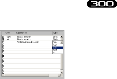
-Finally, if you want to acquire electrogoniometers check the rst
free line in the protocol table, click on the “Type” eld and select
EGN among the voices available in the drop box menu:
55
BTS
Bioengineering
BTS FREEEMG
acquisition protocol
In the same way, click on the “Description” eld and select among
the drop box menu voices the angle you want to acquire with the
EGN, then on the “Side” eld to select the body side to which
the data refers.
- indicate a name for the protocol specifying it on the “Name” box
-it is possible to insert also a short description of the protocol using
the appropriate box “Description”
When every signal of the protocol is inserted, proceed saving the protocol,
following these instructions:
- make sure that the BTS FREEEMG 300 is in the Lab Modality
- click on “Save and Transfer”: the protocol will be both saved on
the PC and transferred on to the BTS FREEEMG 300.
If two receiving units are being used, it is necessary to wait for
the protocol to be transferred to both units. At the end of the
transfer, the protocol will be visible in both, but in each unit will
be displayed only the respective signals from the channels they are

56
BTS
Bioengineering
BTS FREEEMG
acquisition protocol
connected to.
Note that If you are working with two receiving units
the rst 8 channels and the FSW will always be assigned
to the rst unit, while the other, starting from the 9 to
the 16th, will be loaded on the second unit.
For example, if a protocol with 10 EMG channels and
the footswitches has been created, the protocol on the
rst unit will register 8 EMG channels and the FSWs,
while the protocol on the second unit will register only
2 EMG channels.
57
BTS
Bioengineering
BTS FREEEMG
acquisition protocol
Here some guidelines to follow for a correct application of the probes.
Carefully prepare the skin of the subject in the area of the muscle in which
the pre-gelled electrodes will be positioned.
Note that the condition of the skin where the electrodes are
applied inuences the quality of the acquired signal.
erefore you should pay careful attention to this phase in
preparing the subject.
Attach the probes, previously activated (see § ““Active” Button), to the
electrodes using the appropriate clips.
Find the position in which to place the electrode on each muscle that
you want to analyze and apply the probe in the direction of muscle bers
through the pre-gelled already applied to the probe, trying to keep the two
electrodes as close as possible (tangent to each other).
anks to the special hardware architecture of the probes and the
much reduced weight, normally no extra xing is required.
If the analysis protocol being used requires it, proceed to the positioning
of the footswitches to the respective contact areas.
When FSWs are used, these are xed to the skin of the subject used tape
tting the patient
58
BTS
Bioengineering
BTS FREEEMG
acquisition protocol
or hyper-allergenic bi-adhesive tape.
Never apply the tape on the black membrane of the sensor,
removing the tape could cause the detachment of the membrane
making the switch unusable.
After positioning the sensors, connect them by means of the appropriate
connector to the corresponding preactivated probe.
Finally, attach the probe and the switch box with the hypo-allergenic
adhesive tape close to the same switches (i.e. close to the ankle when the
sensor have been placed on the foot sole) at all times taking care to leave
the patient the greatest degree of freedom of movement.
Finally, If the analysis protocol being used requires it, proceed to the
positioning of the Electrogoniometers.
Each EGN should be positioned straddling the joint with the two sti
ends positioned on the sagittal plane, parallel to the axes of the two body
segments that make up the joint under investigation, securing them to the
patient’s skin using the plaster or hypoallergenic double-sided tape.
After positioning the sensors, connect them by means of the appropriate
connector to the corresponding preactivated probe.

59
BTS
Bioengineering
BTS FREEEMG
acquisition protocol
Finally, attach the probe and the switch box with the hypo-allergenic
adhesive tape close to the sensor on the side where the connection cable
comes out.
roughout the dressing procedure of the patient or at the end of it you
can use the receiving unit to check, using the oscilloscope of the “Gains”
function of the RU, the correct placement of the electrodes and control
that the acquisition gain of the EMG channels is properly set.
It’s possible also to compare two channels at a time using the “Cross check”
function (see § “Guide to the use of the onboard software”).
After making all the checks, it is possible to proceed with the acquisition
session.
60
BTS
Bioengineering
BTS FREEEMG
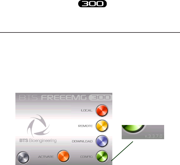
Initial screen
At the start-up of the BTS FREEEMG 300 you see the initial screen
comprised of six buttons: “Local”, “Remote”, “Download”, “Cong”,
“Activate” and “Exit”.
In the lower right hand corner of the main screen there is the version num-
ber of the software installed on board.
“Active” button
e “Active” button allows only those probes to be activated which are
to be used during the acquisition and to assign each of these to a specic
channel.
Click on this button to call up the following display:
guide to the use of onboard software
61
BTS
Bioengineering
BTS FREEEMG
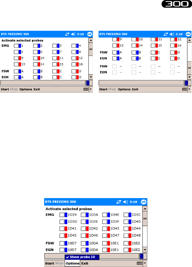
guide to the use of onboard software
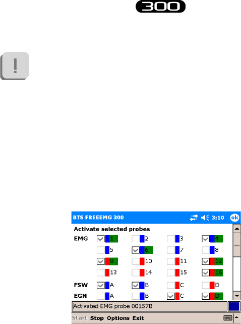
e probes are divided by type: EMG, up to 16 probes for collecting
electromyographic signals, FSW, up to 8 probes for collecting basographic
signals (up to 2 can be selected at the same time), and EGN, up to 8
probes for collecting signals from the electrogoniometers.
A number (or letter) and the color corresponding to the ID tag of the
probe is shown next to each probe.
By clicking on Options and then “Show probe ID” you can pass from
viewing by label to that for viewing by “ProbeID” identication code, the
code shown on the clip of each probe and vice versa:
62
BTS
Bioengineering
BTS FREEEMG
guide to the use of onboard software
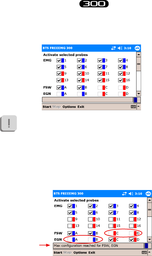
To activate, select the probe that you would like to use for the acquisition
by enabling the check mark in the appropriate box:
It is important to remember that only certain probe congurations
can be activated (for the detailed list of possible congurations,
see § “acquisition unit”).
is procedure will be guided by the software disabling, upon
reaching a conguration limit, all the checkboxes that can no
longer be selected, furthermore, in the notication area at the
bottom, any time the maximum conguration for a type of probe
(EMG, EGN, or FSW) is reached, a warning message will appear
as shown in the following gure:
63
BTS
Bioengineering
BTS FREEEMG
guide to the use of onboard software
Before proceeding to activation, connect the probes to the Charger (or to
the Docking Station) included, use two units if required.
is operation resets the probes, deactivating any probes already active,
except for those probes that are more than 90% charged (in case of
Charger to reset these probes you must wait for the battery level to below
the threshold of 90%).
It is advisable to connect all the probes and not just those used
during acquisition to ensure that you reset any previously activated
probes, which will not be used.
An already active probe can be reused and does not require
reactivation. In this case it must be selected in the activation
program, but do not connect it to the Charger or Docking Station
so it doesn’t reset.
It is in any case necessary that the probes are suciently charged
for the activation to succeed.
Click Start to initiate the probe activation procedure.
Now we would like to distinguish between operations to perform based on
if you use the Charger or Docking Station:
- Charger procedures:
e probes will be activated only when removed from the Charger.
Remove the probes, therefore, from the charger, and wait for the BTS
FREEEMG 300 to activate all the selected probes.
64
BTS
Bioengineering
BTS FREEEMG
guide to the use of onboard software
To facilitate the activation and to verify that all the required probes
are active, we suggest detaching the probes from the charger one
at a time.
- Docking Station procedures:
Click on the Docking Station “Activate” button.
Immediately all the probes selected in the activation probe will be
automatically activated and all the other probes will be reset, regardless
of the charge level.
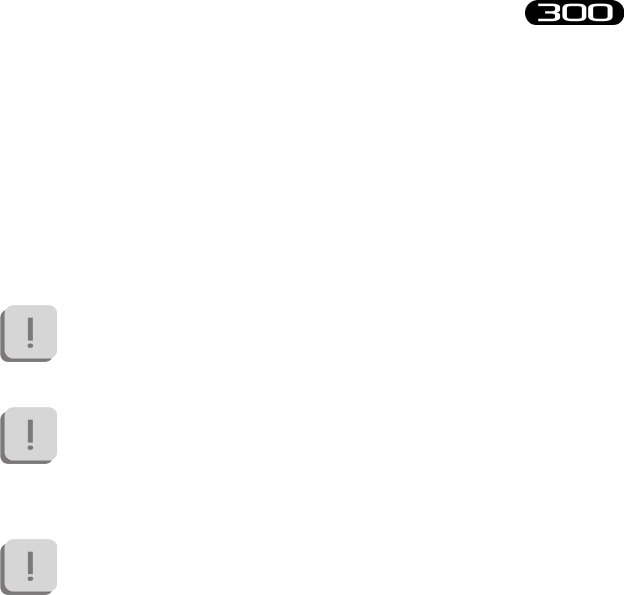
When a probe has been recognized and activated, it will be highlight by a
green rectangle, as shown in the following gure:
When all the selected EMG, EGN and FSW probes are indicated as
activated, click “Stop” to terminate the activation procedure.
Finally, click “Exit” to return to the initial screen.
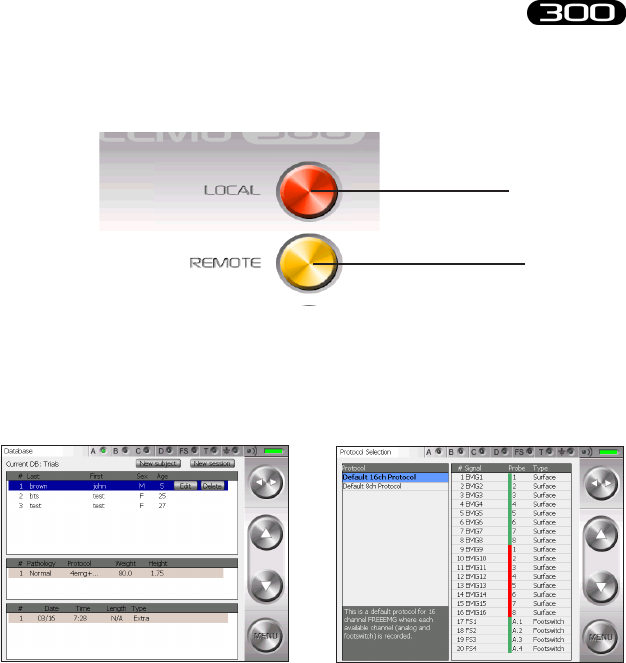
Selecting the work mode
e rst two buttons (Red and Yellow) allows the user to select the desired
65
BTS
Bioengineering
BTS FREEEMG
guide to the use of onboard software
working mode: button “Local” Holter mode, button “Remote” Lab mode.
Clicking on the button for the desired mode, you can enter the software
of relative management.
In particular by clicking on the “Local” and “Remote” buttons you will see
the following screens:
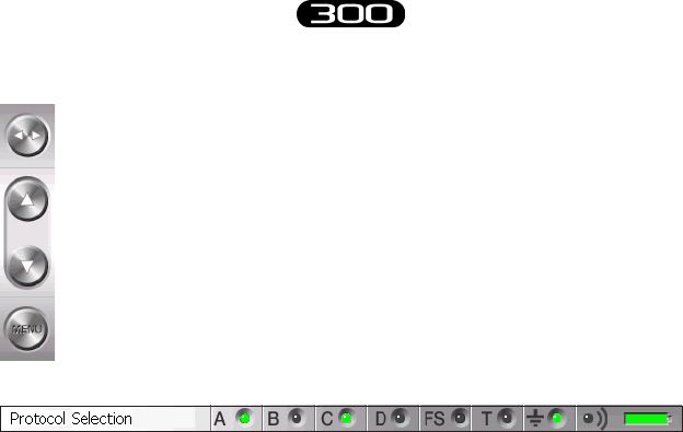
Description of the main bars and menu
All of the BTS FREEEMG 300 pages have a button bar on the right and
a status bar at the top.
Button Bar
Local Acquisition
(Holter Mode)
Remote Acquisition
(Lab Mode)
66
BTS
Bioengineering
BTS FREEEMG
guide to the use of onboard software
e side arrows (Toggles) can be used to change the active eld.
e up and down buttons make it possible to:
• change the value in the active eld
• navigate around the main menu
e menu button opens the main menu
Status Bar
e status bar displays:
• active page
• the condition of the 4 transmitters indicated with A, B, C, D.
One transmitter can serve more than one probe. When a probe
is transmitting the LED of its corresponding transmitter turns
steady green
• e status of the FSWs (steady green LED if at least 1 FSW probe
is active and recognized by the system)
• battery level
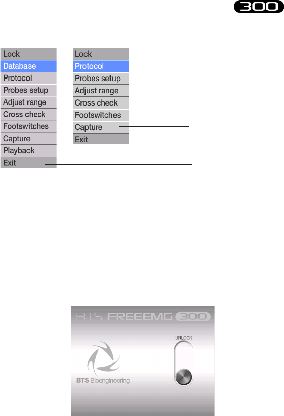
Main Menu
Clicking on the “menu” button of the buttons bar you enter the main
menu.
ere are two menus: one for the Holter mode and one for the Lab mode.
e two are dierent for the items: “Database” and “PlayBack” which exist
only in the Holter mode.
67
BTS
Bioengineering
BTS FREEEMG
guide to the use of onboard software
e main menu allows you to:
- explore the functions of the BTS FREEEMG 300.
To enter a page select the corresponding icon by clicking with
the stylus on the desired function or by using the Up and Down
Buttons.
- lock up the palm by clicking with the stylus on the icon “Lock”.
Accomplishing this function will result in the following screen:
To unlock the palm, clik on the “Unlock” button, this will
Lab Mode Menu
Holter Mode Menu
68
BTS
Bioengineering
BTS FREEEMG
guide to the use of onboard software
immediately move to another position.
To complete this procedure it is necessary to press it again before
it goes back to the original position.
- close the application by clicking on the “Exit” button.
e following describes the menu functions starting from the ones that
you can nd both in the Holter Mode and in the Lab Mode that have the
same characteristics.
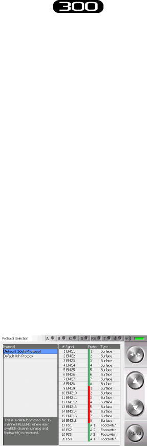
Protocol
is item allows the user to select a protocol from the ones previously
created by the user (see § “Acquisition protocol”).
In any case if a protocol hasn’t yet been created it is possible to use the
default protocol.
Selecting a protocol is achieved by scrolling through the list on the left
panel by clicking on the Up and Down buttons of the buttons bar. e
protocol you select will be highlighted in blue.
69
BTS
Bioengineering
BTS FREEEMG
guide to the use of onboard software
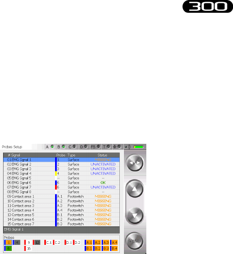
Probes Setup
When a new protocol is dened, the user needs to associate with the items
of the protocol (muscles, joints and foot areas) the channel that physically
acquires the data.
By clicking “Probes setup” from the menu you will see the following
screens:
In particular we can identify two zones:
• the probe-protocol association table
• e “Probes” area
e table, for each signal of the acquisition protocol, previously selected in
the “protocol” section shows:
• the identier of the assigned probe (comprised of the color and
number/letter of the label), if no probe has been assigned the eld is
set on “--”
• the type of probe: Surface, Footswitch, Electrogoniometer,...
• the state of the probe:
• OK: Signal/probe properly assigned, the probe has been

70
BTS
Bioengineering
BTS FREEEMG
guide to the use of onboard software
selected in the activator and is connected to the RU.
• NOT CONNECTED: Signal/probe properly assigned, the
probe has been selected in the activator, but does not appear
to be connected to the RU.
• “--” : no assigned probe.
• NOT ACTIVATED: the probe is assigned to the protocol
signal, but has not been selected in the activator.
• ERROR: the signal/probe has not been properly assigned as
the type of probe expected by the protocol does not match
the actual probe
In the “Probes” area (rectangle at the bottom) where the selected probes in
the activator are listed and the state is described.
In particular, the boxes associated to channels can have dierent colors:
• Green:
the selected probe in the activator is connected to the RU and is
assigned to a protocol signal (the “Status” eld of the protocol is
“OK”)
• Grey:
the selected probe in the activator is connected to the RU but is not
assigned to any protocol signal
• Orange:
the selected probe in the activator is not connected to the RU but
is assigned to a protocol signal (the “Status” eld of the protocol is
“NOT CONNECTED”)
• White:
the selected probe in the activator is not connected to the RU and has
not been assigned to any protocol signal

71
BTS
Bioengineering
BTS FREEEMG
guide to the use of onboard software
• Red:
the selected probe in the activator is connected to the RU and assigned
to a protocol signal, but the type of probe expected by the protocol
does not match the actual probe (the “Status” eld of the protocol is
“ERROR”).
To make the association probe-signal:
1. use Up and Down buttons to select a signal
2. use toggle to select the “Probe” eld
3. choose among the available ones (all the probes present in
the probe area will be proposed), the probe to pair to the
highlighted signal
4. use toggle to select the description (the whole row)
5. move on the next description with the arrow Down and restart
from point 2 to assign the channel to the next item.
Active elds (Toggle) Value range (Select)
Description Signals List
Probe 1, 2, ..., 15, 16, for EMG channels
A.1, A.2, A.3, A.4, B.1, B.2, B.3, B.4,
C.1, C.2, C.3, C.4, D.1, D.2, D.3, D.4,
E.1, E.2, E.3, E.4, F.1, F.2, F.3, F.4,
for EGN and FSW
all available in 4 colors:
Green, Red, Blue, Yellow
72
BTS
Bioengineering
BTS FREEEMG
guide to the use of onboard software
Each Electrogoniometer generates two signals, it is important that
you assign two channels of the same probe to the signals generated
by the same EGN, e.g. C.1, C.2
To properly assign the basographic signals to the FSW probe
channels please remember to match the 4 signals related to one
probe to the protocol signals related to the physically close contact
area, e.g. A.1, A.2, A,3, A.4 for the Right foot and B.1, B.2, B.3,
B.4 for the Left foot.
Before starting acquisition, the user needs to conrm that the
“Status” of each protocol voice is OK.
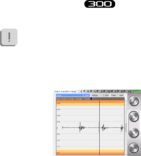
Digital Oscilloscope (gain)
With BTS FREEEMG 300 the user can set up to 3 dierent ranges of
values to see the muscular contractions better.
To setting this value see § “ Cong” Button”.
e selectable values are:
• S1: 6mV;
• S2: 3mV;
• S3: 1,5mV.
By accessing the gains page it is possible to verify that electrodes have
been well positioned (no noise or motion artefacts) and that the signals are
properly displayed and if they are not you can change the range of value

73
BTS
Bioengineering
BTS FREEEMG
guide to the use of onboard software
set in the conguration section.
To do this, simply view via the oscilloscope the real-time muscular activity
of each muscle you would like to analyze for a few seconds, asking the
patient to perform several contractions.
If the intensity of the muscle is very low, so that it is dicult to distinguish
between when the muscle is in contraction from when it is at rest, the range
needs to be reduced (the system will increase the gain correspondingly).
If, on the other hand, the signal in the current amplitude tends to saturate
(meaning during the contraction there are peaks in the orange zone or
beyond), it is necessary to increase the range (the system will reduce the
signal gain accordingly).
Keep in mind that the base range value will be the same for all
signals acquired.
erefore select the value that lets you best see the channels
simultaneously without saturation.
If the selected range is insucient to contain the entire signal
dynamic, the acquisition data will tend to saturate during
the contraction, which will appear as unnatural plateaus in
measurement values at the limits of the selected range.
On the other hand, if the signal is very weak, maintaining a high
range is not a mistake. It is recommended, however, that the range
be reduced whenever possible, in order to make better use of the
digitalization of the acquisition card.
74
BTS
Bioengineering
BTS FREEEMG
guide to the use of onboard software
e gain used in the acquisition of the EMG signals is managed
by the application on the basis of the range selected, the choice
of range should be done with great care since it aects not only
the display but also the acquisition signal (it is not a just a simple
zoom!).
By clicking the voice “Gain” from the menu you will see the following
screens:
To scroll the dierent signals, click on the Toggle to activate the “Signal”
active eld and select the protocol item desired by actuating the Up and
Down buttons.
To make the signal visualization easier it is possible to use the “Time”
active eld (by selecting it with the Toggle) this allows to adjust the speed
at which the signals run on the screen (this is only for display purposes,
and will have no eect on the capture).
It is possible to set the time value interval shown on the axes of the
oscilloscope abscissas, selecting from a range of values from 1 to 10
seconds, that can be selected with the Up and Down buttons.
75
BTS
Bioengineering
BTS FREEEMG
guide to the use of onboard software
Active elds (Toggle) Value range (Select)
Signal Protocol signals
Time 1 sec - 10 sec
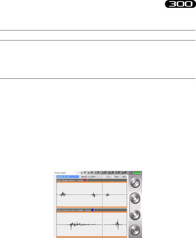
Digital Oscilloscope (cross check)
e Cross Check is very useful during the patient setup phase, allows the
operator to verify, prior to the actual acquisition of the signals, that the
electrodes have been positioned correctly.
e possibility of displaying two traces simultaneously prevents the
problem of cross-talk: this phenomenon occurs as a detection of electrical
activity on the trace of a muscle during a movement which should not
involve the muscle in question.
Cross-talk is occurring if, for example, during the movement of extension
of the wrist, one observes the activity of the ulnar carpus exor.

76
BTS
Bioengineering
BTS FREEEMG
guide to the use of onboard software
is is due to an incorrect positioning of the electrodes, as a consequence
of which the channel dedicated to a certain muscle is in reality measuring
the activity of another muscle.
In the above example, the activity measured on the trace of the ulnar
carpus exor is not in reality being produced by that muscle, but by one
deeper down or by its antagonist.
To appoint the signals to visualize select the “Signal 1” and then “Signal
2” eld with the Toggle and scroll the signal list included in the protocol
using the Up and Down buttons.
e current display can be enlarged or reduced via the zoom function: this
does not aect in any way the data being read.
e “Time” eld can be used to vary the speed at which the signal runs
on the screen (again, this has no eect on the reading, but only on the
display).
It is possible to x the time intervals represented on the axis of the abscissas
of the oscilloscope, choosing from a range of values from 1 to 10 seconds.
Active elds (Toggle) Value range (Select)
Signal 1 Protocol signals
Signal 2 Protocol signals
Zoom From 1/10 to x10
Time From 1 sec to 10 sec
77
BTS
Bioengineering
BTS FREEEMG
guide to the use of onboard software
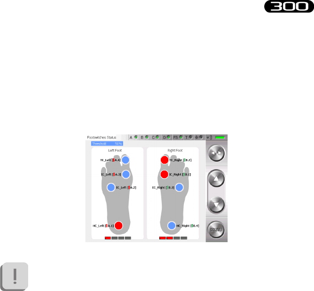
Footswitches
e Footswitches page shows in real time the activation of the contact
zone during the deambulation contact phase.
When a zone is active, the foot is resting on it - the corresponding circle
colors is red.
If there isn’t correspondence between the contact points indicated
on the display and the movements done by the subject (for
example if with the right foot in stance the areas under the left
foot of the display became red) we suggest you to review the FSW
channels setup selecting the menu voice “Probes Setup”.
Usually the Footswitches are used for studying the sole of the foot during
deambulation.
Four points have been identied for this purpose in order to be able to
distinguish the foot tread while walking.
ese 4 areas are:

78
BTS
Bioengineering
BTS FREEEMG
guide to the use of onboard software
• Internal Contact,
• External Contact,
• Heel Contact,
• Toe Contact.
However, while preparing the protocol you can indicate the general
contact areas:
• “Contact area 1”,
• “Contact area 2”,
• “Contact area 3”,
• ...
e Footswitch probes can also be used for other applications and
placed on other parts of the body where you would like to record
the moment of contact (for example on a nger during pointing
exercises).
In this case you should use a general “Contact Area 1”, “Contact
Area 2” in the protocol, and in the FSW page refer to the rectangles
located under the gure showing the foot to check that the probes
are properly activated.
“Local” button: Holter Mode
In this mode the RU is completely independent and it’s possible to acquire
the data independently of the WS.
Session preparation:
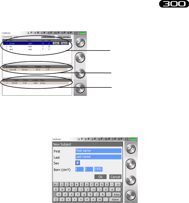
selecting “Local” you can enter the patient’s database on the palm.
79
BTS
Bioengineering
BTS FREEEMG
guide to the use of onboard software
To add a new patient click with the stylus on “New subject” button.
A window will open which allows you to insert general information about
the patient.
To insert the patient data:
• move up to the eld to insert
• insert the value with the keypad, (each tap on the gender eld
will change from F to M and viceversa)
• press OK to insert the patient into the database
List of patients already included in the
database of the BTS FREEEMG 300
List of sessions for the highlighted
patient
List of the tests of the highlighted
session
80
BTS
Bioengineering
BTS FREEEMG
guide to the use of onboard software
It is possible to modify or to delete the data of a patient already inserted.
By clicking on the line of that patient, it will be underlined in light blue
and the “Delete” and “Modify” buttons will appear.
Clicking on “Modify” a window will open that allows to modify the
general information of this patient.
Click on “Delete” and immediately a window with the request to conrm
the deletion will appear:
Clicking on “Yes” the trial will be removed from the database, with all
the related sessions and trials, while if you choose “No” the deletion will
be aborted.
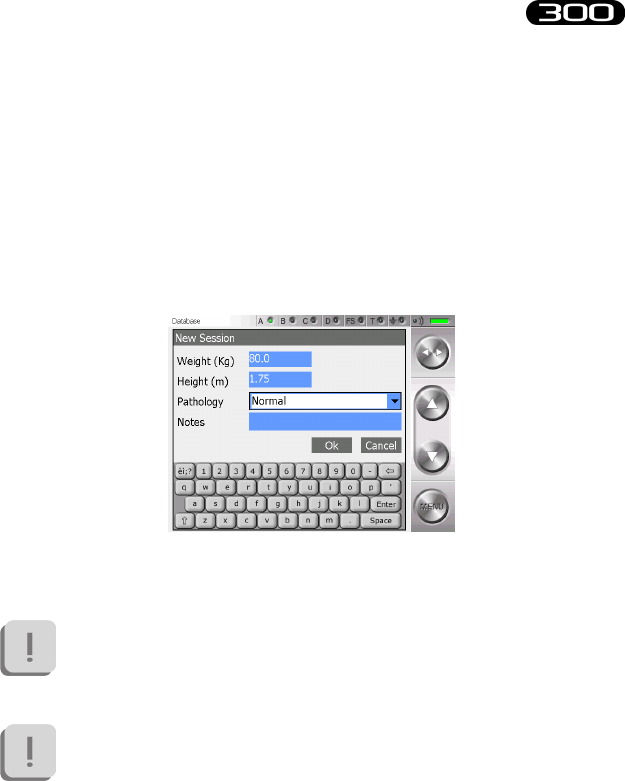
81
BTS
Bioengineering
BTS FREEEMG
guide to the use of onboard software
To create a new test session click on “New Session”.
A window will open that allows to the user to insert data linked to the
session:
• patient weight
• patient height
• pathology
• possible notes of the session
Press “OK” to add the session of the selected patient.
e default protocol is linked to the session; to change the
protocol click on the Menu button and enter the “Protocol” item
(see § “Protocol”).
Cautious that it is not possible, rather than, to change protocol of
a session when this has already got some acquisitions.
To continue working with the same patient but with a dierent
protocol it is necessary to create a new acquisition session for that
patient.
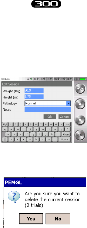
82
BTS
Bioengineering
BTS FREEEMG
guide to the use of onboard software
To modify or to delete the data of a session created previously click on the
correspondent line, it will be underlined in light blue and the “Delete” and
“Modify” buttons will appear.
Clicking on “Modify” a window will open that allows to modify the data
related to this session:
Click on “Delete” and immediately a window with the request to conrm
the deletion of the session and the relate trials will appear:
Clicking on “Yes” the session and the trials will be removed from the
database, with all the related sessions and trials, while if you choose “No”
the deletion will be aborted.
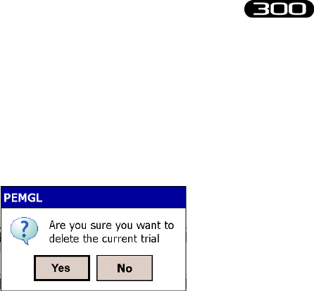
83
BTS
Bioengineering
BTS FREEEMG
guide to the use of onboard software
Latter it is possible to delete single trials. To do that click on the
correspondent line, it will be underlined in light blue and the “Delete”
buttons will appear.
Click on “Delete” and immediately a window with the request to conrm
the deletion of the trial will appear:
Clicking on “Yes” the selected trial will be removed from the database,
with all the related sessions and trials, while if you choose “No” the
deletion will be aborted.
Acquisition:
to proceed with the acquisition in “Local” mode it is necessary to have
created a new session and to have selected an analysis protocol or to have
selected a session already in the database.
Proceed then with the operations described in the previous paragraphs:
“Probes Setup”, “Range”, “Digital Oscilloscope”, “Footswitches”.
Once nished all the preliminary operations and the necessary checking it
is possible to proceed with the acquisitions.
To do that, select the item “Capture” from the Menu.
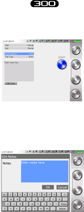
84
BTS
Bioengineering
BTS FREEEMG
guide to the use of onboard software
A screen will appear, which gives the setup for that acquisition:
For every test it’s possible to indicate the Start and Stop mode, the
acquisition frequency and the type and notes of the test.
To edit the notes click on “Edit Notes”, a window will open which allows
you to edit the notes.
Introduce the note using the keyboard and then click on “OK” to conrm
or on “Cancel” to come back to the previous screen without saving the
text just typed.
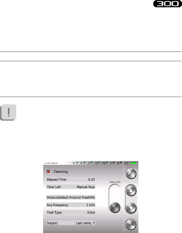
85
BTS
Bioengineering
BTS FREEEMG
guide to the use of onboard software
To modify the other acquisition parameters select the relative eld with
the Toggle and then use the Up and Down buttons.
Active elds (Toggle) Value range (Select)
Acq. Frequency 1KHz, 2KHz, 3KHz, 4KHz
Flag MMT, Resting, Walking, Undened, Extra
If the acquisition frequency selected is 3 or 4KHz, the system can
acquire 8 EMG channels maximum.
If the selected protocol requires a higher number of probes a
warning message will appear and the acquisition won’t be allowed.
By clicking on the “Start” button, the acquisition starts and the system
automatically goes into Lock mode, showing the following:
To unlock the palm click on the “Unlock” button, this will immediately
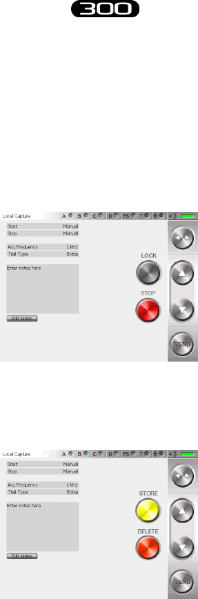
86
BTS
Bioengineering
BTS FREEEMG
guide to the use of onboard software
move to another position.
To complete this procedure it is necessary to press it again before it goes
back to the original position.
Before quitting this mode the screen with the acquiring setup reappears
but the “Start” (or “Arm”) button is substituted with the “Unlock” and
“Stop” buttons.
e “Unlock” button allows to come back to the previous screen.
Clicking on “Stop”, instead, will end the acquisition.
At this point the following screen will be visualized:

87
BTS
Bioengineering
BTS FREEEMG
guide to the use of onboard software
To save data on BTS FREEEMG 300 select “Store” whereas to cancel the
data just acquired click on “Delete”.
In this case a conrmation for the cancellation will be asked of the user,
select “Yes” if you want to delete the new acquired data.
Click“No” button” and then “Store” to save the test.
After the storing or the cancellation of the last acquired test you are
redirected to the screen containing the “Start” button.
To continue with another acquisition click on “Start” and repeat the
operations just described. If any other acquisition won’t be executed, select
“Exit” from the menu.
Playback
In the Holter mode it is possible to visualize a preview of the data acquired
and saved in the database.
To do that, from the menu select the voice “Database” and select the
patient, the session and the trial that you want to visualize clicking with
the stylus on the correspondent line, that will be underlined in light blue.
Once the trial is selected, from the menu select the voice “Playback”.
At the end of an acquisition session it is possible to go directly to the
“Playback” page, without passing from the “database”: in this circumstance
all the trials saved in the last session acquired will be loaded.
In both these circumstances the following screen will appear:
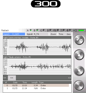
88
BTS
Bioengineering
BTS FREEEMG
guide to the use of onboard software
From the lower panel select the trial to visualize by tapping on the
correspondent line.
It is possible to visualize two signals at the same time.
To do that select the eld “Signal 1” and than “Signal 2” using the Toggle
and scroll the list of the available signals operating on the Up and Down
buttons.
After that to improve the signal visualization, adjust the active elds
“Zoom” and “Time” selecting them with the Toggle and changing their
value with the Up and Down buttons.
In particular the “Zoom” eld allows increasing or reducing the current
view area (it acts on the axis of ordinates), while the “Time” eld allows
changing the temporal value range showed on the axis of the abscissas,
choosing among a range of value in between 1 and 10 seconds.
is means that the selected trial will not be entirely visualized, but only
bits of the length of 1, 2, 5 or 10 seconds according with the “Time” eld.
89
BTS
Bioengineering
BTS FREEEMG
guide to the use of onboard software
Active elds (Toggle) Value range (Select)
Signal 1 Protocol signals
Signal 2 Protocol signals
Zoom
Time From 1 sec to 10 sec
# Trial Trials of the selected session
However it is possible to scroll the whole trial changing time after time the
frame from where the visualization starts.
To do that click with the stylus on the grey band that represents the whole
trial in the point correspondent to the rst frame to visualize.
On the grey band at the two extremities, are indicated the beginning of
the trial (that is 0:00) and the total length of it (like in the example in the
gure 0:34, that means 0 minutes and 34 seconds).
In the spot in which you tap, a grey rectangle will appear in which will be
indicated the correspondent time of the selected rst frame (like in the
example in the gure 0:21).
erefore, if the “Time” eld is set, for example, on “5sec”, we are
visualizing 5 seconds of trial starting from the 21st second.
It is possible, if you regard it relevant, delete some trials.
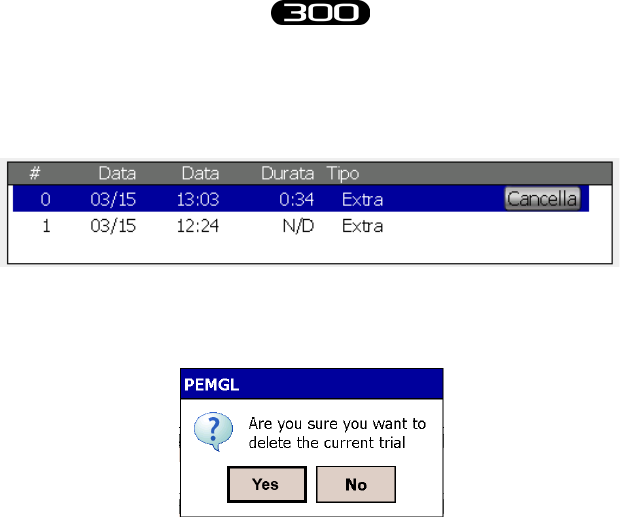
90
BTS
Bioengineering
BTS FREEEMG
guide to the use of onboard software
Click on the trial, choosing it in the lower panel, that you want to delete.
It will be underlined in light blue and the “Delete” button will appear.
Click on “Delete” and immediately a window with the request to conrm
the deletion will appear:
Clicking on “Yes” the trial will be removed from the database, while if you
choose “No” the deletion will be aborted.
Importing data to EMG-Analyzer
e data acquired in Holter mode is saved in a local database in the BTS
FREEEMG 300. To execute the elaboration and the analysis of the data,
you need to import the test using the software EMG-Analyzer.
To do this, proceed as described further in § “Download button”.
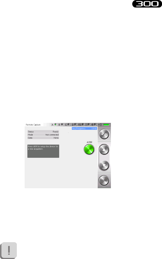
91
BTS
Bioengineering
BTS FREEEMG
guide to the use of onboard software
“Remote” button: Lab mode
In this mode the connection between RU and WS is always available.
e specic characteristics are:
• sending data boxes to the WS for the visualization in the remote
oscilloscope, available in the applicative software.
• data transfer at the end of acquisition.
• the duration of acquisition and the Start/Stop are controlled by
the PC.
Selecting “Capture” from the main menu the following screen appears:
is screen displays some information concerning the system:
• Status: Ready mode
• Mode: Stand Alone
• Data: None
To make an acquisition in Lab mode, there must be no
data saved on the BTS FREEEMG 300.
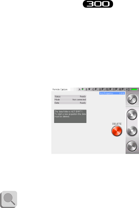
92
BTS
Bioengineering
BTS FREEEMG
guide to the use of onboard software
is possibility can happen only with a loss of WiFi connection between
BTS FREEEMG 300 and Workstation during the last acquisition, or if
the data transfer has not gone well.
In this case the screen displayed after having selected “Capture” from the
main menu will contain instead of the “Arm” button, the “Delete” button
and the “Data” eld will be “Ready”.
If you want, it is possible to recover the lost data saved in the RU
before proceeding with the new acquisitions downloading them on the
Workstation using the EMG-Analyzer software.
To know the download procedure consult the manual of EMG-
Analyzer.
Otherwise the data will have to be deleted and cannot be retrieved in the
future.
To delete the data, click on the “Delete” button; by doing this the system
will ask you a conrmation for the deletion, select “Yes” if you really want
to delete the data in a permanent way, otherwise click on “No” to come
back to the previous screen.
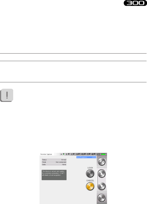
93
BTS
Bioengineering
BTS FREEEMG
guide to the use of onboard software
Once deleted the le, the “Arm” button appears again and the “Data” eld
will again become “None”; so it’s possible to proceed with the acquisition.
Before arming the system it is possible to set the acquisition frequency
using the Up and Down button of the button bar.
Active elds (Toggle) Value range (Select)
Acq. Frequency 1KHz, 2KHz, 3KHz, 4KHz
If the acquisition frequency selected is 3 or 4KHz, the system
can acquire 8 EMG channels maximum. If the selected protocol
requires a higher number of probes a warning message will appear
and the acquisition won’t be allowed.
To prepare the system for capture it is necessary to “arm” it by simply
tapping the “Arm” button that will be replaced by the “Lock” and the
“Cancel” buttons.
Now it is possible to make the acquisition via remote control.
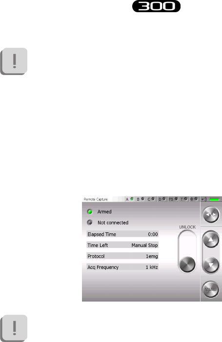
94
BTS
Bioengineering
BTS FREEEMG
guide to the use of onboard software
At this level it is not possible to change the acquisition frequency.
Tapping on the “Cancel” button the previous screen appears, returns
control to the RU.
To proceed with the next acquisition, the system needs to be armed again.
It is possible to lock the system by clicking on “Lock” directly by this
window, therefore at the beginning of the acquisition the BTS FREEEMG
300 locks automatically displaying:
e acquisition starts-up through the remote control, directly by
the Workstation.
is display will remain on the BTS FREEEMG 300 until the acquiring
session is over.
It’s possible to interrupt the acquisition remotely and proceed with the
next ones.

95
BTS
Bioengineering
BTS FREEEMG
guide to the use of onboard software
At the end of every acquisition an automatic data download will be
executed. Only at the end of the download is it possible to launch another
remote acquisition.
Once the acquisition session is over, unlock the BTS FREEEMG 300.
In order to do so, press the “Unlock” button, this will immediately move
to another position.
To complete this procedure it is necessary to press it again before it goes
back to the original position.
Finally to quit from the “Armed” status click on the “Cancel” button.
For the details of the remote management of the acquisition from
the WS refer to the specic manual of the software meant to be
used.
Download Button
If the Holter mode is chosen (local acquisition), the acquisitions are saved
in a local database to BTS FREEEMG 300.
To elaborate the acquired data with the dedicate softwares installed on
the Workstation, the user needs to download them with EMG-Analyzer
following these instructions:
• Select from the main page the download mode clicking on the
“Download” button
• BTS FREEEMG 300 keeps waiting, showing the following
screen:
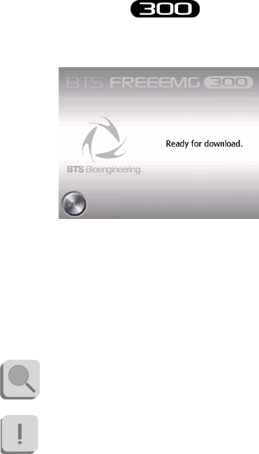
96
BTS
Bioengineering
BTS FREEEMG
guide to the use of onboard software
• From EMG-Analyzer, select the “View Local Database” item
from the “Laboratory” menu.
• A window will appear that will allow you to explore and modify
the active database on the BTS FREEEMG 300, and download
all the les that you are interested in.
For further details concerning the data download refer
to the user manuals of EMG-Analyzer software.
e data import takes place with a wireless connection;
if the import operation fails, you need to verify that
the RU and WS are connected (see § “Appendix C –
troubleshooting guide”).
• When the download is nished on the BTS FREEEMG 300
keep pressing the “Exit” button to go back to the main screen.

97
BTS
Bioengineering
BTS FREEEMG
guide to the use of onboard software
“Cong” button
e “Cong” button launches an application that allows the modication
of some system settings.
It uses ve tabs to reach the dierent information and features:
• Info:
Main screen that contains information of the installed versions.
• General:
General settings (i.e. language, audio settings...).
• Radio:
Associates the ID identier of each EMG and FSW/EGN probe
to its label identied by color and number/letter;
setting of the signal range;
setting the radio channels utilizing the probes.
• Database:
Database management.
• Maintenance:
session permitted only to BTS Technician sta, for assistance.
For this reason to access this area a Password is required.
To execute any changes of the parts that can type on it is possible to use
the touch-screen features of the display and where necessary, activate the
keyboard, clicking on the low right corner icon represented by a little
keyboard.
To exit this application and come back to the main screen, you must tap
on the “Ok” button, placed in the top right corner.
One tap on this button will conrm all the changes made.
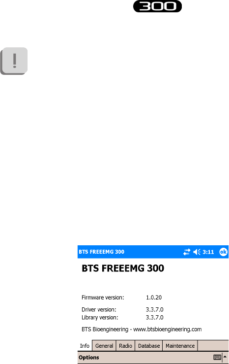
98
BTS
Bioengineering
BTS FREEEMG
guide to the use of onboard software
It won’t be possible to undo the changes made, apart setting again,
manually the previous values.
All the changes made are immediately activated, therefore, in some
circumstance, it will be necessary to restart the BTSFREEEMG300
application to see these changes applied (for example when you change
the language).
Let’s analyze now, more in depth, the four tabs that the user can modify.
Info
Clicking on the “Cong” button on the main screen, it automatically
selects the application screen in which the tab Info is selected:
On this page it is possible to read all the information about the versions of
each installed component, hardware or software.
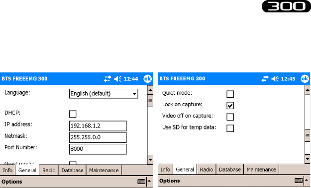
99
BTS
Bioengineering
BTS FREEEMG
guide to the use of onboard software
General
Selecting “General”, the following screen will be visualized:
It is possible to set:
• e language
• “DHCP”, for automatic host conguration, the “IP address”
and “Netmask”, available only with the “DHCP” not checked,
to manually assign the connection parameters and the “Port
Number”.
• “Quite mode”: Checking this voice, the program will play
without any noise (instead of what normally happens when for
example you Tap on a button or activate an acquisition…)
• “Lock on Capture”: Checking this voice when an acquisition
starts the BTS FREEEMG 300 will be automatically locked
showing the “Unlock” button
• “Video o on Capture”: if checked, the display automatically
will switch-o at the acquisition beginning. To activate the
screen again a click on one of the PocketPC button is enough
• e use of a Secure Digital memory card to store the temp le
generated during the acquisition (check this voice only if there is
a Secure Digital board in the related port).
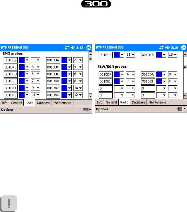
100
BTS
Bioengineering
BTS FREEEMG
guide to the use of onboard software
Radio
When “Radio” is selected the following page is displayed:
e “EMG probes” and “FSW/EGN probes” sections allow to associate
the ID that uniquely identies each probe manufactured by BTS S.p.A.
with the probe’s label.
e ID is shown on the clip of every EMG probe and on the back of every
FSW/EGN probe.
Up to 16 EMG probes and up to 8 FSW/ EGN probes can be registered.
Probes that are not registered in this section will not be recognized
by the Receiving Unit and therefore may not be used for
acquisitions.
Generally, the system is distributed to the customer with this association
already made.
However it could be useful if new probes are purchased or if probes are
replaced due to a malfunction.
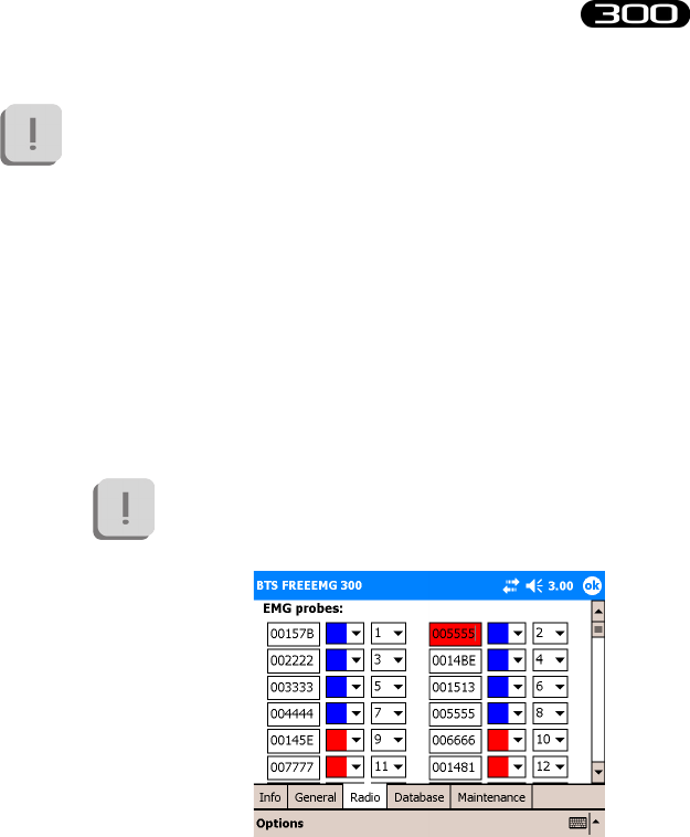
101
BTS
Bioengineering
BTS FREEEMG
guide to the use of onboard software
However when you receive the system it is advisable to check
that the association has been made correctly. If a probe has been
incorrectly associated to a label or the ID number does not match
that on the clip the probe may not work. Instead, changing
two IDs compared to the label could cause an exchange of
acquisition signals as well and therefore cause false results in the
Electromyographic examination.
Follow the procedure below, to register a probe that has not been
introduced:
• Enter the ID of the probe using the keypad that can be activated
on the bottom right-hand side of the page.
If the string entered is not admissible or has already
been entered the software will highlight it in red.
• Select the color of the probe’s label (the colors can be Red,
Green, Blue, and Yellow) using the drop down menu.
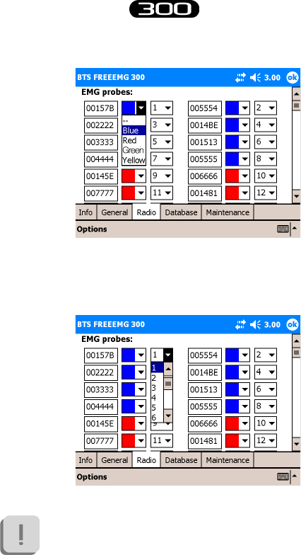
102
BTS
Bioengineering
BTS FREEEMG
guide to the use of onboard software
• Finally, select the number or letter shown on the probe’s label
(number selection from 1- 16, letter selection from A-F).
If the label (identied by the color/ number or letter
combination) has already been used the software will
highlight the ID string in red.
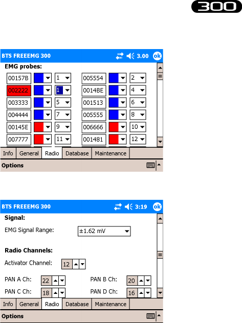
103
BTS
Bioengineering
BTS FREEEMG
guide to the use of onboard software
From the Radio page two other sections may be accessed.
e “Signal” section allows to select the Range for electromyographic
signals. 3 dierent value are available:
• 6,34mV;
• 3,17mV;
• 1,62mV
From the “Radio Channels” section the ZigBee channel with which to
work can be assigned to the activator and the four transmitters.
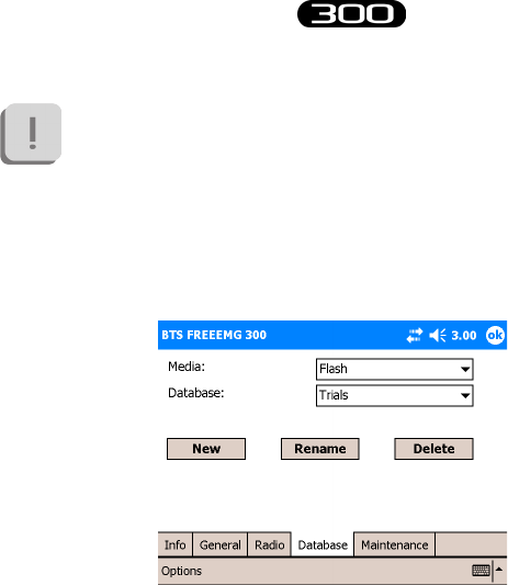
104
BTS
Bioengineering
BTS FREEEMG
guide to the use of onboard software
It is recommended to modify this section only if absolutely
necessary and eventually with referral to BTS technical support.
Database
Selecting “Database” the following screen will be visualized:
In this section it is possible to select the current database, to create new
databases, to delete and rename existent databases.
ere are two list-boxes, the rst one, “Media”, allows the selection of the
box in which the database can be found or to insert a new one.
In particular there are two possible medias: the ash memory, internal to
the Pocket PC and the Secure Digital card.
If the latter is not present, a message will be visualized indicating that the
card is not inserted.

105
BTS
Bioengineering
BTS FREEEMG
guide to the use of onboard software
Instead the error message:
“ERROR: media not initialized”
will be visualized if the card has been inserted but hasn’t still been initialized.
In this circumstance a button will appear allowing the initialization.
Once selected the “Media” it is possible operating on the second list-box
to select the database to use.
Mind that if the selected Media is empty, it is necessary to create
a new one.
To create a new database click on “New”.
e new database will be created with the default name “TrialsDB”.
To change the name select it and click on “Rename”.
To delete a database select it and click on “Delete”.
is operation removes completely the database and all its content
(patients, sessions and trials).
For this reason the system will ask a conrmation before
proceeding with the deletion.
“Exit” button
e “Exit” button allows the closing of the application and the visualization

106
BTS
Bioengineering
BTS FREEEMG
guide to the use of onboard software
of the operative system installed on the PDA.
To do that it is enough to press and hold the “Exit” button for few seconds.
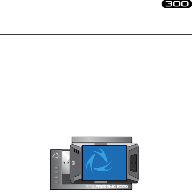
107
BTS
Bioengineering
BTS FREEEMG
Updating the onboard software
To update the BTS FREEEMG 300, exit the application by selecting the
entry of the Exit menu and holding down the “Exit” button for some
seconds.
Before carrying out the upgrade of the software it is recommended a
backup be made of the software version currently installed.
Slide the PDA out of the methacrylate guide enough to disconnect the
Compact Flash. Connect the PDA via the dedicated cable to the USB port
of the WS.
On the WS, from Windows, run the update program, launching the
“BTSFREEEMG300Setup.exe” le, and follow the video instructions till
the update is complete.
Reinsert the PDA in the AU.
Restart the “BTSFREEEMG300” application on the BTS FREEEMG
300: from the Start menu, click on “Programs”, search for the
“BTSFREEEMG300” icon and single click it. e main screen will appear.
BTS FREEEMG 300 updating
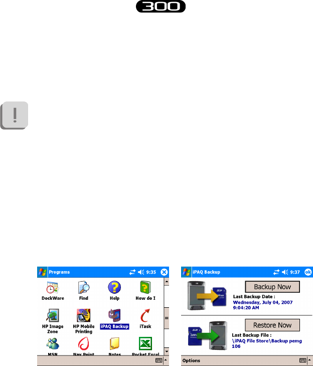
108
BTS
Bioengineering
BTS FREEEMG
BTS FREEEMG 300 updating
Creating a backup image
At the end of each software upgrading, it is important to remember to
create a backup image.
It can happen that the Pocket PC battery goes completely
dead. When this happens all the BTS settings as also the
BTSFREEEMG300 software will be lost. To restore the software
and bring the BTS FREEEMG 300 to the standard conguration
it will be enough to proceed with the restore of the last backup
done (see Appendix D – Troubleshooting guide).
To do the backup proceed as follow:
• exit from the BTSFREEEMG300 application holding the
button “Exit” for some seconds
• select “Start” and then “Programs”
• among the installed programs, choose “iPAQ Backup”:
• with the stylus tap on “Restore Now” and wait the end of the
backup procedure.
e Pocket PC will restart and then the BTSFREEEMG300
software will be automatically reloaded.

109
BTS
Bioengineering
BTS FREEEMG
BTS FREEEMG 300 updating
e backup procedure is now nished, therefore we suggest to rename the
backup le created giving it a more meaningful name, in particular we
recommend to indicate the version number of the software.
To do that proceed in this way:
• exit from the application
• select “Start” and then “Programs”
• among the installed programs, choose “File Explorer” click on
the arrow that appears on the grey bar, under the title “File
Explorer” and choose “Device”
• open the folder “iPAQ File Store”
• look for the backup le just created that will have a name like:
Backup_2007-07-15, where the date is the one during the
backup time
• with the stylus, tap and hold for few seconds on the backup le
icon till when the menu appears
• choose rename and type the new name (i.e. Backup_v107
supposing you have updated the software with the version
1.2.107.0).

110
BTS
Bioengineering
BTS FREEEMG
Periodically inspect the PDA and the slide of the receiving unit for any
signs of detachment, cracks or other damage.
Clean the external parts periodically with cleaning liquid approved for
computers. On the PDA monitor use a microbre cloth only, and do not
use liquid detergents or solvents.
Contact with the skin of the patients is achieved via the pre-gelled Ag/
AgCl electrodes, which, being single-use disposable, intrinsically guarantee
a suciently high level of hygiene.
Generally you use hypoallergenic band-aid or hypoallergenic double-
sided tape to apply the Footswitches in correspondence of the foot contact
points.
At the end of each work session, it is important to carefully remove every
glue or gel residual from these parts and from the probes.
After each use we suggest to clean the switches using a soft cloth moist with
a disinfectant solution, being careful removing any glue residual left.
e BTS FREEEMG 300 cannot be sterilised.
maintenance and cleaning

113
BTS
Bioengineering
BTS FREEEMG
appendix A
technical specications
Wireless Probes
Geometry: variable
Electrodes: standard with clip connection
Separation: min: 16mm - max: 66mm
Autonomy: 8h of use
some days stand-by
some months deep sleep
Battery: rechargeable, lithium ion
Dimensions: 14x41,5x24,8mm mother electrode
diameter 16x12mm satellite electrode
Weight: 13g battery included
Frequency used: ISM band
2.4GHz (standard IEEE802.15.4)
Input impedance: >10 GOhm
CMMR: >110 dB @ 50-60Hz
Resolution: 16bit
Acquisition frequency: up to 4KHz
Sensitivity: 1μV
Aaccuracy of measurement*: ± 2%
Receiving Unit
Autonomy: up to 24h with rechargeable battery
up to 9h with single battery
Battery: rechargeable, lithium ion

114
BTS
Bioengineering
BTS FREEEMG
appendix
Dimensions: 155x106x35mm
Weight: 360 grams
Frequency used: ISM band
2.4GHz (standard IEEE802.15.4
and IEEE802.11b)
Display: 4” VGA color touch-screen
* e system is calibrated at the factory. No further calibration is required
BTS internal coding
Name of device, components, parts and/or
accessories as per product label
Identier for
device (bar code,
catalogue, model
or part number)
FREEEMG 300
Pocket PC with Stylus
Acquisition unit
Belts and armbands for attachment to patient
• 16 EMG probes
FREEEMG 300
FootSwitch/Electrogoniometer Wireless Probe
Foot switches: Insole individual foot switches for
the automatic identication of the gait events.
Electrogoniometers: Sensors for the measurement
of joint angles progress over the time.
FRESPU12

115
BTS
Bioengineering
BTS FREEEMG
Name of device, components, parts and/or
accessories as per product label
Identier for
device (bar code,
catalogue, model
or part number)
Fine-Wire adapter : Adapter for the Fine-Wire
electrodes. FRESPU23
O-Port expander : Digital to Analogue EMG data
converter. FREALG16
EMGenius: software application to acquire,
elaborate and report electromyography and
footswitch signals EMGE0901
EMG-Analyzer: software application for EMG
signal analysis SMAN0901
Docking station FRESPU05
Charger FRESPU06

116
BTS
Bioengineering
BTS FREEEMG
appendix B
environmental specications
Min Max Note
Operating Temperature -20° +45°
Operating Humidity 50% 80% Relative,
non-condensing
Storage and Transport
Temperature 0° +40°
Storage and Transport
Humidity 50% 80% Relative,
non-condensing
Altitude 0m 2000m
Degrees of protection provided by the dangerous enclosures of water and
dust (IEC 60529): IPX0.

117
BTS
Bioengineering
BTS FREEEMG
appendix C
power supply and switch o
e medical power supplier TR30RAM050 provided with the system has
the following functionality:
- Provide power to the Receiving Unit and recharge its battery.
-Guarantee the galvanic insulation of the Receiving Unit from the power.
To switch o the system the following operation must be done:
- Stand-By of the Receiving Unit:
1) push the graphical button “MENU” and then select “Exit” to quit the
application.
2) set the Receiving Unit state on “stand-by” by clicking on the switch
-on/o button of the PDA.
- Stand-By of the Probes:
place the probes on the “Charger” or “Docking Station”.

118
BTS
Bioengineering
BTS FREEEMG
BTS FREEEMG 300 is an internally powered device: several of its
components use batteries as indicated below.
e Probe battery replacement can be done only by BTS qualied
personnel.
e probes are sealed to avoid the access to the internal circuit
components.
Batteries are equipped with battery protection circuit to:
-over-voltage, threshold 4.3V
-under-voltage, threshold 2.8V
- short-circuits
e specic characteristic of the dierent components of the system
equipped with the battery are:
- Receiving Unit
Quantity: 1 per each unit
Technology: lithium ion (Li-Ion)
Removable: yes, by removing the PDA from the acquisition
unit
- Wireless Probes
Quantity: 1 per each EMG or FSW/EGN probe
Technology: lithium polymer (Li-Poly)
Removable: NO, BTS technical service is required
appendix D
battery

119
BTS
Bioengineering
BTS FREEEMG
appendix
- Docking Station (optional)
Quantity: 1 for each unit
Technology: lithium polymer (Li-Poly)
Removable: NO, BTS technical service is required

120
BTS
Bioengineering
BTS FREEEMG
DECLARATION OF CONFORMITY
BTS SpA
Via della Croce Rossa 11, 35129 Padova (PD) – Italy
Tel. +39 049 981 5500 Fax +39 049 792 9260
declare under our sole responsibility that the product(s):
name / description: Electromyographic system / device for recording myoelectrical activity.
model: FreeEMG300
S/N: SN
satisfies the essential requirements of the Medical Devices Directive 93/42/EC (and its amendments inluding
2007/47/CE), and therefore carries the CE marking of the European Union. The conformity assessment procedure is
according to the article 11 of the directive (Annex II.3 full quality assurance) and the article 12 it is not applicable.
In accordance with Annex IX of the 93/42/EC directive it is classified as follow:
CLASS “IIa” (rule 10)
In accordance with IEC 60601-1 is also classified as follow:
Class: internally powered device Applied part type: BF
The product conforms to the following standards:
EN ISO 14971 Medical Devices - Application of risk management to medical devices.
IEC 60601-1 Medical Electrical Equipment - Part 1: General Requirements for basic safety and
essential performance.
IEC 60601-1-2 Medical Electrical Equipment - Part 1-2: General requirements for basic safety and
essential performance - Collateral standard: electromagnetic compatibility -
Requirements and tests.
IEC 60601-1-6 Medical Electrical Equipment - Part 1-6: General Requirements for basic safety and
essential performance - collateral Standard: Usability
EN 62304 Medical device software - Software life-cycle processes
ETSI EN 301 489-3 Electromagnetic compatibility and Radio spectrum Matters (ERM) – Electromagnetic
Compatibility (EMC) – standard for radio equipment and services – Part 3: Specific
conditions for Short-Range Devices (SRD) operating on frequencies between 9 KHz and
40 GHz.
ETSI EN 301 440-2 Electromagnetic compatibility and Radio spectrum Matters (ERM) – Short Range Devices
(SRD) – Radio equipment to be used in the 1 GHz to 40 GHz frequency range – Part 2:
Harmonized EN covering essential requirements of Article 3(2) of the R&TTE Directive.
This compliance is valid ONLY for the equipment identified when used in a manner consistent
with the intent of the referenced documents and according to the product’s usage manual.
Notified Body : TÜV Product Service GmbH, Zertifizierstelle, Ridierstrasse 65, 80339 München – Germa-
ny, Identification N. 0123.
EC certificate N. G1 12 10 65301 003 valid until January, 16 2018.
Padova, Date
Bruno Ros
CEO
BTS S.p.A.
appendix E
declaration of conformity
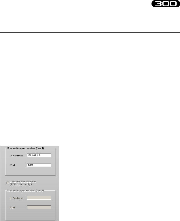
121
BTS
Bioengineering
BTS FREEEMG
1708 Error – Incorrect IP address or port set up
e software uses IP address parameters and communication ports to cre-
ate network connections between the Workstation and the PDA.
In the case of incorrect conguration, the correct parameter values need
to be re-input.
To do this, launch the software that you are going to use and then, by the
menu voice “Laboratory” select “Set Emg Device”.
Verify that the IP address and the port setting are correct.
e values to specify are the following:
IP Address: 192.168.1.2
Port: 8000
and if a second receiving unit is available:
IP Address: 192.168.1.3
Port: 9000
If necessary, correct the values and click on “Upgrade” before closing the
windows.
appendix F
troubleshooting guide

122
BTS
Bioengineering
BTS FREEEMG
appendix
1709 Error – Impossibility to connect to the unit
One or more Wi-Fi network resources (Access Point, Workstation, PDA)
are not available.
In general, we recommend some simple checks as follows:
- Access Point
Check they are correctly connected to the power supply and
switched on.
Try switching the AP o and then back on. Since some models are
not tted with an On/O switch, it may be necessary to remove
and reinsert the power cable.
If on the rear of the model there is a selection button, verify it is
on position AP
- Workstation
If the Workstation is tted with a Wi-Fi interface, check it is
active and connected to “BTSFREEEMG300”.
As the connection is through the AP, check that the LAN (local
area network) is active.
- BTS FREEEMG 300
e Wi-Fi connection is active only when the BTS FREEEMG
300 is in Remote Mode or in Download Mode.
From the main screen choose one of these two mode.
If the connection is still not activated, also with all these settings,
please contact the BTS Customer Care.
Backup restoring
e backup restoring procedure allows the reloading of the
123
BTS
Bioengineering
BTS FREEEMG
appendix
“BTSFREEEMG300” software and the restoring of the standard
conguration of the Pocket PC. is is very useful, for example, when
the PDA battery goes completely dead. If this happens, when the PDA
is switched on, the software “BTSFREEEMG300” won’t be loaded and,
instead of it, a screen will appear in which the system will ask the user to
execute some start-up operations.
In this circumstance, before proceeding with the restoring
procedure, it is necessary to complete the start-up operations
required by the system that consists in the execution of some
simple exercises like the stylus pointing, to execute a copy and
paste, etc...(for further details refer to the PDA manual).
When all these operation are nished, the windows main screen
will be visualized and it will be possible to proceed with the
restoring of the last backup.
To restore the backup follow these instructions:
• select “Start” and then “Programs”
• among the installed programs, choose “iPAQ Backup”:
• click on “Restore Now” to restore the last backup, the PDA
will restart and then the “BTSFREEEMG300” software will be
reloaded
• at this point, exit from the application to set the date and the
time, to do that select the date under the voice “Start”.
For further details about the time and date setting refer to the
PDA manual.
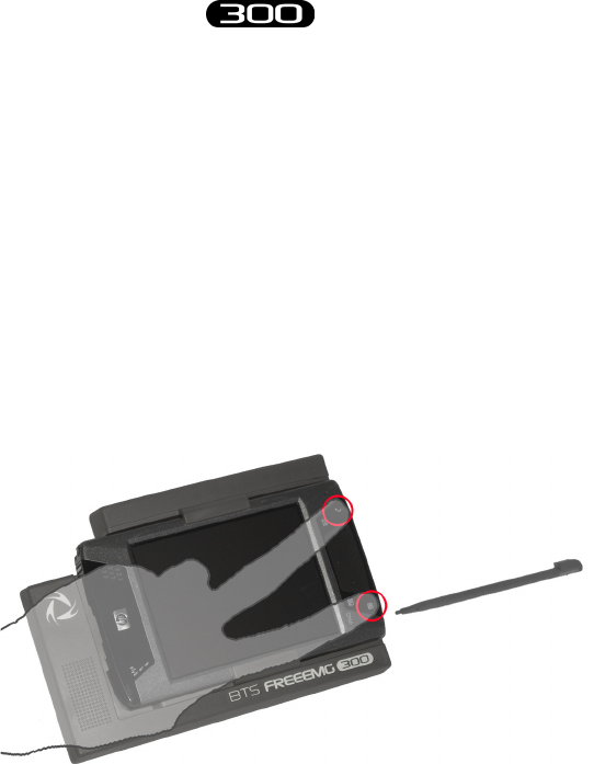
124
BTS
Bioengineering
BTS FREEEMG
appendix
Receiving unit hardware reset
In case the PDA blocks during use and does not respond to any commands,
you must perform an hardware reset operation.
To do that follow these instructions:
• place the receiver on a plane;
• grip with your right hand the PDA stilus;
• using index and middle nger of your left hand push the two
buttons (marked by the icons keypad and arrow) positioned at
the right of the PDA display and simultaneously, with your right
hand, insert the stylus in the hole on the right side of the PDA,
as shown in the gure below:
Immediately the system will be rebooted;
• when the PDA will switch on again the software
“BTSFREEEMG300” won’t be loaded and, instead of it, a
screen will appear in which the system will ask the user to execute
some start-up operations; complete the operations required that
consists in the execution of some simple exercises like the stylus

125
BTS
Bioengineering
BTS FREEEMG
appendix
pointing, to execute a copy and paste, etc...(for further details
refer to the PDA manual).
• when all these operation are nished, wait for the windows main
screen to be visualized;
• nally proceed with the restoring of the last backup procedure
described in the previous paragraph.

BTS Bioengineering Corp.
147 Prince Street - Suite 11
11201 Brooklyn NY
USA
info: +1 347 204 7027
helpdesk: +1 646 575 0426
BTS S.p.A.
viale Forlanini 40
20024 Garbagnate M.se MI
Italy
tel +39 02 366 490 00
fax +39 02 366 490 24
www.btsbioengineering.com
info@btsbioengineering.com