BTS BTSWEMG2 Wireless EMG sensor for EMG system User Manual EREMB 01091 06 FREEEMG 100 RT ENG v 2 0 3
BTS SpA Wireless EMG sensor for EMG system EREMB 01091 06 FREEEMG 100 RT ENG v 2 0 3
BTS >
Contents
- 1. EREMB-01091-06 FREEEMG 100 RT User Manual ENG v.2.0.3
- 2. ERFNC-00782-16 FREEEMG 300 User Manual ENG v.4.0.3
- 3. ERTMJ-00998-04 TMJOINT User Manual ENG v.3.0.0
EREMB-01091-06 FREEEMG 100 RT User Manual ENG v.2.0.3
version 2.0.3
user manual
english
Document Number : EREMB-01091-06
Published: June 2013
Copyright © 2010 - 2013 BTS SpA. All Rights Reserved.

1
BTS
Bioengineering
contents 1
icons, symbols and acronyms 3
radio regulation 7
disposal (WEEE) 8
intended use 9
regulatory label 10
receiving unit regulatory label 10
EMG wireless probes regulatory label 10
AUX wireless probes regulatory label 11
BTS charger regulatory label 12
warnings 13
copyright 16
introduction 17
general description 17
case contents 18
system components 21
receiving unit 21
wireless EMG probes 22
wireless FSW/EGN probes (optional) 25
on-o analysis (optional) 27
electrogoniometers (optional) 29
charger 30
installation 33
user PC minimum conguration 33
connections 33
contents
2
BTS
Bioengineering
contents
hardware installation 34
description of the software on the user PC 37
BTS EMG-Analyzer conguration check 38
acquisition protocol 41
appendix A – technical specications 47
wireless probes 47
receiving unit 47
BTS internal coding 48
appendix B – environmental specications 49
appendix C – power supply and switch o 50
appendix D – battery 51
appendix E – troubleshooting guide 52
warning – invalid trigger mode 52
appendix F – declaration of conformity 53
appendix G – regulatory notice 54
FDA medical device reporting system—reportable events 54
adverse event report (21 CFR 803.32) 55
3
BTS
Bioengineering
icons, symbols and acronyms
Symbol in the instructions for the function.
e icon represents the information which requires special attention.
Symbol in the instructions for the function.
is icon makes reference to a more detailed discussion of the subject in
hand.
Symbol on the equipment:
e data appearing next to the manufacturer’s symbol refer to the place of
manufacture of the equipment itself.
Symbol on the equipment:
e “FCC” simbol refers to the Federal Communication Commission of
the USA. e device complies with the relevant regulations put forth by
the FCC as long as it is operated according to the instructions contained
in this manual and to all national and local regulations.

4
BTS
Bioengineering
icons, symbols and acronyms
Symbol on the equipment:
e gure in the square indicates the insulation class and the part types
used. In accordance with Standard ISO 60601-1, the equipment has an
internal power supply and the parts used are type BF.
Symbol on the equipment:
Attention, read the information in the users’ manual carefully before using
the equipment.
Symbol on the equipment:
e double square indicates that the product is a medical device of II
Class (In accordance with the law EN 60601-1).
Symbol on the equipment:
CE mark with the code of the Notied Body. e CE mark certies that
the product conforms to the standards applicable in the member states of
5
BTS
Bioengineering
icons, symbols and acronyms
the European Union (see Declaration of Conformity).
Symbol on the equipment:
CE mark with the code of the Notied Body. e CE mark certies
that the product conforms to the Directive 99/05/EEC - R&TTE and
obtained the Expert Opinion by IMQ.
Symbol on the equipment and in the users’ instructions:
Symbol for the separate disposal of electrical and electronic equipment, in
accordance with Directive 2002/96/CE (WEEE).
e equipment belongs to Group 8 (medical equipment).
In force in the nations of the European Union, Norway and Switzerland.
Rx only
Symbol for prescription only. U.S. Federal law restricts this device to sale
by or on the order of a physician or properly licensed practitioner.

6
BTS
Bioengineering
icons, symbols and acronyms
REF
Symbol on the equipment:
Symbol located next to the model number (ref.to catalogue).
SN
Symbol on the equipment:
Symbol located next to the series number on the equipment.
Acronyms used in this manual:
RU Receiving Unit
EMG Electromyography
WS Workstation

7
BTS
Bioengineering
radio regulation
Radio equipment identication:
- EMG probes:
FCC ID: YQH-BTSWEMG2
IC: 9188A-BTSWEMG2
- FSWEGN probes:
FCC ID: YQH-BTSWAUX
IC: 9188A-BTSWAUX
- Receiving Unit contains:
FCC ID: TFB-MATRIXLP
IC: 5969A-MATRIXLP
is device complies with part 15 of the FCC Rules. Operation
is subject to the following two conditions: (1) is device may
not cause harmful interference, and (2) this device must accept
any interference received, including interference that may cause
undesired operation.
Modications not expressly approved by BTS SpA could void the
user’s authority to operate the equipment under FCC rules.
8
BTS
Bioengineering
disposal (WEEE)
In disposing of the equipment observe the legal prescriptions.
In accordance with Directive 2002/96/CE (WEEE) all equipment supplied
after 13/08/2005 may not be disposed of in general domestic waste. is
equipment belongs to Category 8 (medical equipment) and is classied in
the Business-to-Business sector.
e symbol of the crossed out rubbish bin
indicates that the equipment must not be
disposed of in normal domestic waste.
e regulations for disposal may dier between
individual countries in the EU. In cases of doubt,
refer to the respective sales outlet.
is is a battery-powered equipment.
See Appendix D for information about the batteries used. Operate
and dispose of this equipment according to the instructions set in
the “warnings” section.

9
BTS
Bioengineering
intended use
is equipment is an instrument for the EMG surface analysis, classied
as medical equipment in accordance with European Directive 93/42/CE
(and its amendments).
BTS FREEEMG 100 RT must always be used only for this purpose, by
qualied persons, in an environment suitable for the execution of EMG
analyses and respecting the prevailing regulations in the countries in which
it is being utilized.
10
BTS
Bioengineering
Probe ID
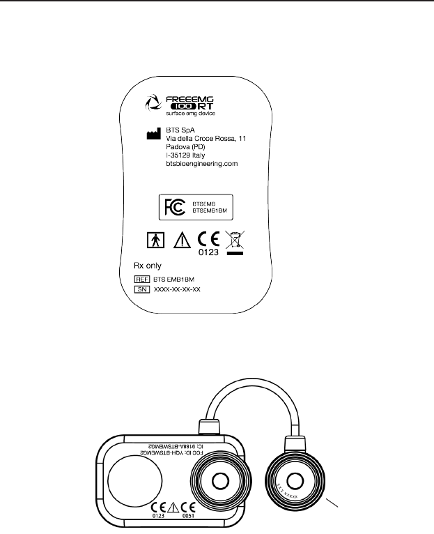
regulatory label
Receiving Unit Regulatory label
EMG Wireless Probes Regulatory label
Label on the probes:
11
BTS
Bioengineering
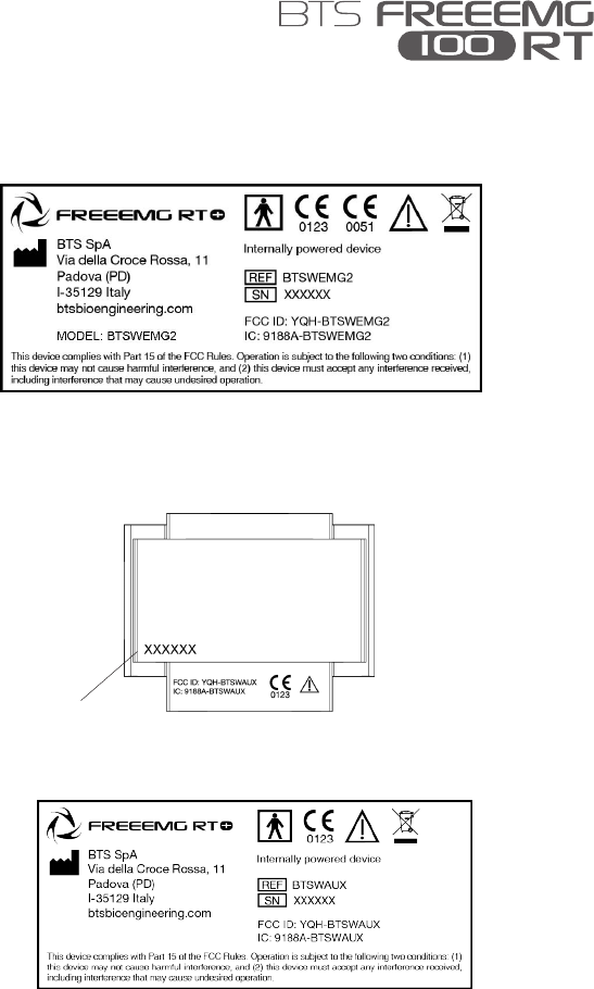
regulatory label
Label not on actual probes due to size constraints:
AUX Wireless Probes Regulatory label
Label on the probes:
Label not on actual probes due to size constraints:
Probe ID
12
BTS
Bioengineering
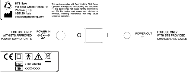
regulatory label
BTS Charger Regulatory label
3A
3A 9V
3A 9V
13
BTS
Bioengineering
We recommend to carry out any kind of operation keeping
strictly to the security regulations contained in this manual. e
safety of the instrument cannot be guaranteed if these conditions
are not respected.
BTS FreeEMG 100 RT is a medical device (EU Directive 93/42/CE and
its amendments, including Directive 2007/47/CE) which use must be at
all times be supervised by qualied and authorized personnel, according to
the laws in force in the nation it is in use. e EMG probes are classied as
ETSI EN 300 440 “Receiver category 3” according to Directive R&TTE
99/5/EEC.
e results of the acquisitions must be assessed by people legally authorised
by national law, who possess the suitable necessary knowledge of anatomy
and muscular function.
e instrument must be used in a medical environment, since it has a high
level of sensitivity (measured voltage levels of between 1 microvolt and 6
millivolt).
e uses of the device for other purposes and with methodologies
dierent from of those indicated in this manual are not to be
considered congruent with the precise use of the device.
During the preparation of the patient, take particular care that the system’s
components do not impede in any way the normal movements of the
subject. Apply the probes only on undamaged skin.
warnings

14
BTS
Bioengineering
warnings
• Only use CE branded probes and hypoallergenic double-sided tape,
compatible with the usage on undamaged skin for brief periods of time
• Periodically verify the integrity of the system and of its components.
• To not wet or dip in water the parts which make up the system.
No modication of this equipment is allowed.
• Only BTS S.p.A. authorized technicians may maintain and operate
servicing to the instrument. BTS S.p.A. cannot be held responsible
for system safety should the instrument be opened, repairs carried out,
third parties software be installed, or system components be replaced by
persons other than those authorized by BTS S.p.A.
• Users cannot change any software conguration (including O.S. and
CD writer software).
• In case the device accidentally falls, tear of the probes or other accidents
always address authorized technical support.
• Use only the provided power supply unit FW7363M/09 (FRIWO) or
the one provided by BTS S.p.A. for supplying the charger unit. If a
dierent power supply unit is used, the compliance to IEC 60601-1 is
not ensured.
• Only original cables must be used, otherwise BTS S.p.A. cannot assure
the safety of the instrument. Should it be necessary to replace any part
of the system, only original BTS S.p.A. parts may be used.
In addition to the users’ instructions, the prescriptions regarding
accident prevention and technical regulations regarding
occupational safety must also be complied with. e appertaining
national regulations and standards of the country of use, with
regards prevention of accidents and environment, are an extension
of the users’ instructions.
15
BTS
Bioengineering
warnings
• Make sure that the cables have been connected correctly. When
disconnecting cables, use the connectors and not the cables themselves
to unplug the connectors.
• Mains plug of external power supply unit is considered as disconnecting
device. Avoid connecting the probes to the charger with inverted
polarity with respect to that shown on the cover of the recharger – is
could cause irreparable damage to them.
• For a safe use and adequate maintenance of rechargeable batteries strictly
follow the instructions given in this manual. If rechargeable batteries
are used in such a way that is not the one specied by BTS S.p.A. the
shelf life, functionality and the integrity of the batteries is not ensured.
• ESD application to EGN probes, causes a loss of link to the device.
Temporary loss of function or performance which is recoverable with
operator action.
BTS FREEEMG 100 RT is a device that is able to function
COUNTINUOUSLY, this is of course limited by the battery
duration and by the memory available for the acquisition data
storing.
e device uses lithium ion battery. For the battery replacement
and disposal please contact the technical support. At any rate,
ensure that device component (i.e.) probes, receiving unit, …)
integrity is never compromised.
e information contained in this manual is subject to change
without notice and does not constitute product specications or
any obligation on the part of BTS S.p.A.

16
BTS
Bioengineering
copyright
e software of the system described in this manual is supplied with the
“licence to use” contract. e software may be used or copied only as
stipulated under the terms of this contract.
No part of this manual may be copied or transmitted in any form or
means, electronic or mechanical, including photocopying, without prior
written permission from BTS S.p.A.
Unless otherwise specied, any reference to companies, names, data and
addresses used in the reproduction of the screens and the examples are
purely incidental, and has the sole purpose of illustrating the use of the
BTS product. All trademarks are registered by the respective owners.
is publication contains reserved information which is the
property of BTS S.p.A.
e recipient acknowledges that the illustrations and information
supplied in this manual shall not be made available to third parties
without explicit written agreement by BTS S.p.A.

17
BTS
Bioengineering
General description
BTS FREEEMG 100 RT allows for a functional evaluation and a real-
time visualization of the acquired signals for biofeedback and monitoring
applications.
at makes it an indispensable instrument in the elds of sport,
rehabilitation, ergonomics, neurology and orthopaedics.
With BTS FREEEMG 100 RT the patient set up in very quick: the
lightweight probes are attached directly to the pre-gelled electrodes and do
not require any additional xing such as adhesive tape. anks to the total
absence of cables the patient can move around freely.
BTS FREEEMG 100 RT is supplied with EMG-Analyzer the most
complete software solution for analyzing electromyographic signals and
with BTS MIOFEED, an easy-to-use therapeutic solution, studied also
for home applications.
BTS EMG-Analyzer software includes predened templates for evaluations
in the clinical, sports, and research eld: Jump, plyometrics, walking,
fatigue analysis, isokinetic, etc...
BTS EMG-Analyzer also has an editor for creating elaboration protocols:
thanks to an innovative object interface, that translates the biomechanical
analysis language into graphical form, the user can develop quickly and
eectively customized analysis protocols.
introduction
18
BTS
Bioengineering
introduction
BTS MIOFEED software allows a real-time monitoring of muscular
activations during rehabilitative or sports tests execution.
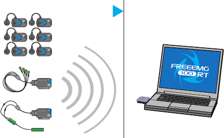
e EMG signal acquired with BTS FREEEMG 100 RT are transmitted
in real-time directly at the receiving unit connected to the PC and
transformed in graphic form and sounds to provide a prompt audio-visual
feedback to the subject. is increase of audio and visual aerences is
fundamental in order to improve the contractile capacities of the muscles.,
also of the paretic ones.
BTS FREEEMG 100 RT seamlessly integrates with BTS motion analysis
systems, through the SMART (and ELITE) dedicated software.
Case contents
Standard components:
• Receiving Unit
• Up to 6 wireless EMG probes (identicative labels available in 4 dierent
colors)
• Magnet for EMG probes activations
19
BTS
Bioengineering
introduction
• Probes Charger (AC adapter included)
• Set of disposable electrodes
• USB extension cable
• User manual
Optional components:
• Footswitch Kit
• 2 FSW/EGN Wireless Probes • 2 Connectors of 4 Switches
• 10 single Switches
20
BTS
Bioengineering
introduction
• Electrogoniometer Kit
• 1 FSW/EGN Wireless Probe • 1 Electrogoniometer
• 1 Connector
You will receive the instructions for use for other possible optional
components not mentioned in this manual.
21
BTS
Bioengineering
BTS FREEEMG 100 RT system consists of two parts: the receiving unit
and the wireless probes.
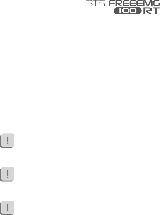
Receiving unit
e receiving unit, connected to the PC trough USB, allows the WiFi
reception of the signal acquired by the wireless probes.
e receiving unit is able to handle simultaneously 6 wireless probes with
the following limitations:
• up to 6 EMG probes, used for acquisition of the same number
of electromyographic signals;
• up to 2 probes for the connection of 4 switches each, used for
the basographic acquisition;
• up to 6 probes for electrogoniometers connection, used for
acquisition of up to 2 angle components each;
• it is not possible to acquire simultaneously FSW and EGN
probes.
system components
22
BTS
Bioengineering
system components
All the probe combinations that respect what indicated above are possible.
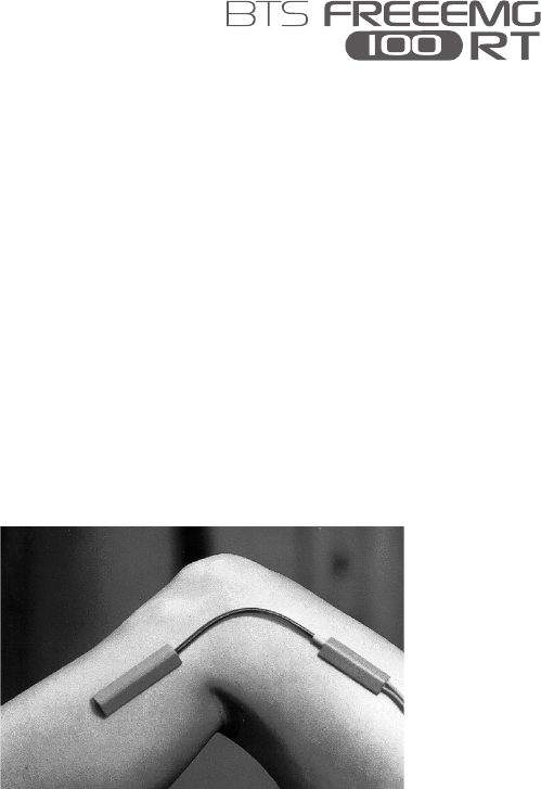
Wireless EMG Probes
BTS FREEEMG 100 RT utilizes miniaturized probes with active electrodes
weighing less than 13 grams.
e special design ensures maximum space-saving and comfort for the
patient who is free to move around without obstacles.
e probes can be hooked on directly to the pre-gelled electrodes without
requiring additional xing with plasters or double-sided tape.
is together with the total absence of cables enables a much faster patient
preparation, drastically reducing the time of each session.
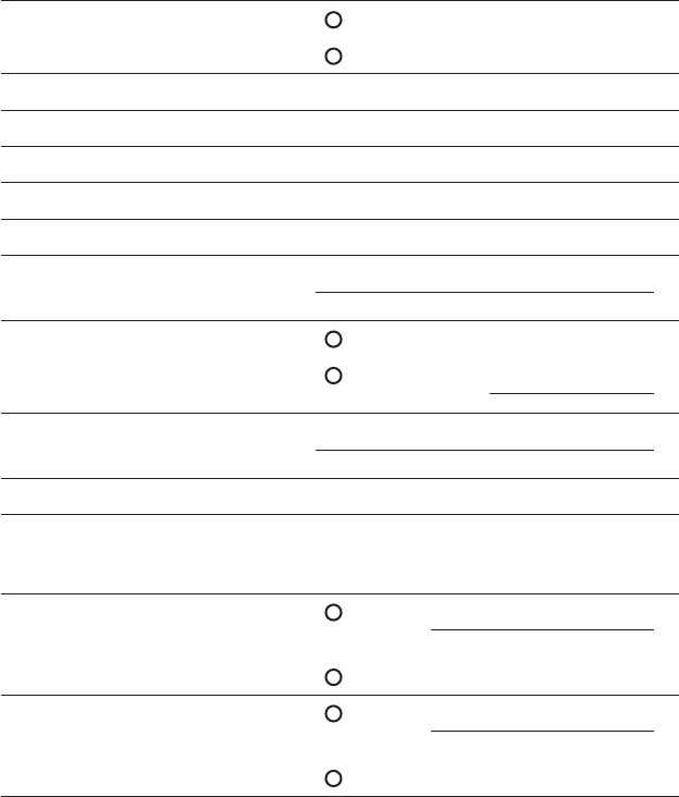
Each probe consists of a mother electrode and a satellite electrode, each
tted with a clip. e two parts, connected via a exible cable, may be
positioned as needed by the user at adjustable distance (electrodes with
variable geometry).
7
WiFi transmission

23
BTS
Bioengineering
system components
All probes are equipped with a solid state memory buer, to prevent data
loss for problems due to the WiFi network or due to exceeding the useful
operating range.
Each probe is tted with an LED indicating its state.
e probes can be in one of a number of dierent states:
• Charge: steady blue LED.
During the recharging phase the steady blue LED is on.
is phase occurs when the probes are connected to the charger
turned on, and the charge level is less than 90%.
When the charge level reaches 90% the led turns OFF.
Since, by connecting a probe to the charger on, it enters in “Deep
Sleep” mode, even while charging the probe will be completely
passive and does not respond to any commands.
• Active-Scanning: white LED which cyclically lights for a few
seconds.
In this mode the probe is searching for the receiving unit.
At intervals of about 1 minutes it carries out a scan of the
frequencies of few seconds. During the scan the white LED
ashes quickly.
1
2
3
4
5
mother electrode
LED
satellite electrode
mother electrode clip
satellite electrode clip
exible cable
probe ID
6
7
5
1
2
2
5
3
4
6
7

24
BTS
Bioengineering
system components
• Active-Connected: white LED which ashes slowly.
When the probe and the receiving unit establish a connection,
the white LED begins to pulse slowly: the probe is waiting for
commands.
If the connection is interrupted, the probe returns to “Active-
Scanning” mode and attempts to re-establish the connection
with the receiving unit.
• Active-Capturing: white LED which lights and goes out at
regular intervals.
During acquisition the white LED ashes at regular intervals of
approximately one second. At the conclusion of the acquisition,
the probe returns to the “Active-Connected” condition.
If during the acquisition, connection to the receiver unit is lost,
the probe continues to acquire, storing the data locally for one
minute and at the same time scans the assigned channel trying
to reconnect to the receiving unit. If after one minute the scan
is unsuccessful, the probe returns to the “Active-Scanning”
condition interrupting the storage of data.
• Completely discharged or in “Deep Sleep” mode: LED is o.
If the probe is completely discharged the LED does not display
any ashing cycle and is o.
e same happens when it is in “Deep Sleep” mode (except
during the recharging phase in witch the led is steady blue).
e probes in “Deep Sleep” mode do not perform any
scan cycle, but are turned o. Is therefore guaranteed
energy savings.
25
BTS
Bioengineering
system components
To put the probe in “Deep Sleep” mode it is necessary to connect
them to the Charger switched on, or to put them in contact
with a magnet for half a second.
Before the next use is necessary to reactivate the probes,
putting them in contact with a magnet.
e probes are charged by a dedicated charger to which the probes are
connected via their respective clips.
For more info about the probes charge sse the paragraph “Charger”
of this chapter.
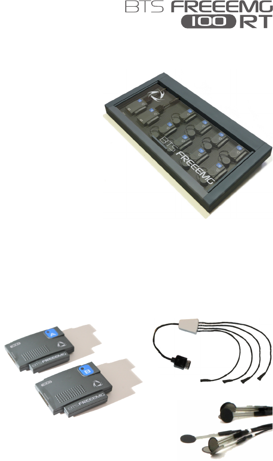
Wireless FSW/EGN Probes (optional)
For collecting the on-o analysis signals coming from the Footswitch or for
collecting data from the Electrogoniometers (optional system components)
BTS FREEEMG 100 RT uses wireless probes which must be connected to
the FSW or EGN probes using a special connector.
e probe will work dierently if used with one or the other probe
and will receive from the same receiving unit information on its
work modality during activation.
26
BTS
Bioengineering
system components
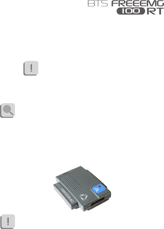
e probe consists of a single parallelepiped-shaped block.
e upper face has an ID tag characterized by a color (Green, Red, Yellow,
Blue) and a letter (A, B, C, D, E or F) and a status LED.
e probes can be in one of a number of dierent states:
• Charge: steady red LED.
During recharging the red LED is on, the probe is completely
passive and does not respond to any command.
When the battery is fully recharged or when the probe is removed
from the charger, if suciently recharged it passes to the “Active-
Scanning” mode.
• Active-Scanning: green LED which cyclically lights for a few
seconds.
In this mode the probe is searching for a receiving unit.
At intervals of about 3 minutes for 3 seconds its carries out a
scan of the frequencies.
During the scan the green LED ashes quickly.
• Active-Connected: Green LED which ashes slowly.
When the probe and the receiving unit establish a connection,
the green LED begins to pulse slowly: the probe is waiting for
commands.
If the connection is interrupted, the probe returns to “Active-
Scanning” mode and attempts to re-establish the connection.
• Active-Capturing: Green LED which lights and goes out at
regular intervals.

27
BTS
Bioengineering
system components
During acquisition the green LED ashes at regular intervals of
approximately one second.
At the conclusion of the acquisition, the probe returns to the
“Active-Connected” condition.
If during the acquisition, connection to the receiver unit is lost,
the probe continues to acquire, storing the data locally for one
minute and at the same time scans the assigned channel trying
to reconnect to the receiving unit.
If after one minute the scan is unsuccessful, the probe returns
to the “Active-Scanning” condition interrupting the storage of
data.
• Probe discharged: LED is o.
If the probe is completely discharged the LED does not display
any ashing cycle and is o.
e two lateral faces have two connectors; the one on the ID tag side
serves to charge the probe, and a cable will be connected to this to enable
connection to the Charger.
e one on the other side is for the probe connections (FSW or EGN).
Finally, the ID identier of the probe is on the bottom left corner of the
back side.
On-o analysis (optional)
e Footswitches are useful in dening the contact points during the
contact phases of deambulation.
28
BTS
Bioengineering
system components
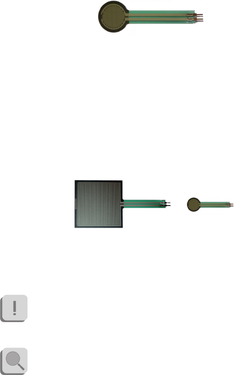
e footswitches consist of a resistive membrane, (FSR technology), of
diameter 18 mm and thickness less than 0.5 mm, expressly designed for
applications in the analysis of movement.
e compact size of the instrument permits a maximum of exibility in
positioning on the patient’s foot.
For applications other than gait analysis, there are available on request
smaller diameter (8 mm) switch probes (applicable, for example, to the
nger), and square (useful for tapping tests), 44 mm x 44 mm.
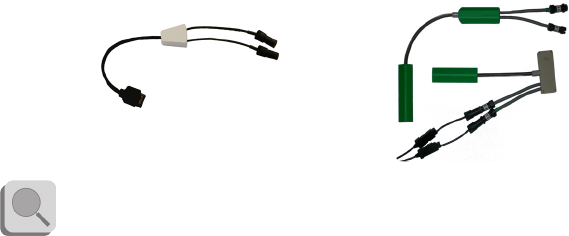
BTS FREEEMG 100 RT permits up to 8 basographic zones to be
measured, through 2 connectors from 4 single switches (usually right and
left side) that are connected to the two FSW/EGN wireless probes.
e footswitch channels are not supplementary to the 6
electromyographic channels. Moreover it is not possible to acquire
simultaneously FSW and EGN.
Refer to § “receiving unit” for the possible probes combination.
29
BTS
Bioengineering
system components
Electrogoniometers (optional)
e Electrogoniometer is an easy to use device that allows the measurement
of joint angle progress over time.
ere are primarily two types of electrogoniometers: the potentiometer
and the strain gauge. BTS FREEEMG 100 RT uses the strain gauge
electrogoniometer of Biometrics LTD.
ere are single-axle models for the neck (axial rotation) and the forearm
(prone-supination) and biaxial models for other main joints: wrist, elbow,
knee, ankle, hip and back.
e strain gauge electrogoniometers are made up of two sensors, connected
to each other, that are xed to the bone segments involved in the joint to
value.
e measure of the angle is provided by the relative angle between the
axes of the two sensors and, unlike the potentiometric electrogoniometers,
it doesn’t depend on the linear slidings in which the two extremities can
incur.
Each electrogoniometer is connected to a FSW/EGN wireless probe
30
BTS
Bioengineering
system components
using the appropriate connector. Each receiving unit can handle up to 6
electrogoniometers.
e EGN channels are not supplementary to the electromyographic
ones, each EGN probe replace a EMG probe. Each EGN probe
allows acquiring up to two angular components. Moreover it is
not possible to acquire simultaneously FSW and EGN.
Refer to § “receiving unit” for the possible probes combinations.
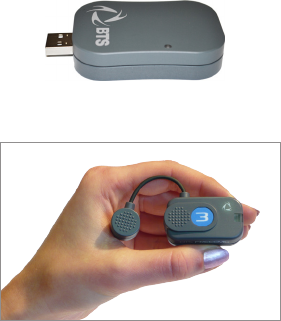
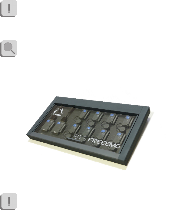
Charger
e Charger, included with the product, charges the BTS FREEEMG 100
RT probes.
e Charger can simultaneously charge up to 8 EMG probes and 2 FSW/
EGN probes.
More units can be connected in series for simultaneous power
supply through the same AC adapter, using the cable included.
31
BTS
Bioengineering
system components
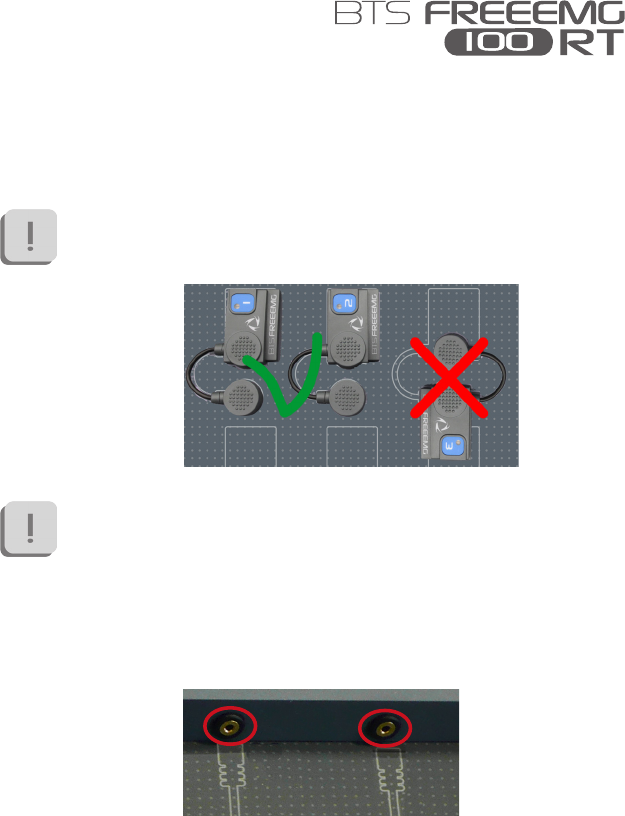
e EMG probes are connected to the charger using the same clips that
normally collect the EMG signal.
Refer to the cover of the charger to identify the correct polarity.
e probes cannot be recharged if the polarities are inverted.
e Charger comes with an output short circuit protection
system also in case of reversed recharging poles. At any rate, poles
connected incorrectly will not recharge.
While the FSW/EGN probes connect to the charger using the special
connector as shown in the gure below:
To recharge connect all the probes that you would like to charge to the
Charger (follow the instructions described above) and connect the AC/

32
BTS
Bioengineering
system components
DC adaptor to the mains and turn on the switch located on the rear panel.
When the Charger is properly connected to the mains and has been turned
on, the status LED “Power” will show a steady GREEN light.
e charging status of the EMG probes and of the FSW/EGN
probes is indicated by the respective status LED (see § “Wireless
EMG Probes” and “Wireless FSW/EGN Probes”).
Note that inserting the EMG probes into the Charger when it is
on, these come in “Deep Sleep” mode.
It is necessary to reactivate the probes, prior to use them, using a
magnet.

33
BTS
Bioengineering
User PC minimum conguration
Operating system Windows 7
Processor Intel Dual Core
RAM 2 GB
Video resolution 1280x800
Disk space 100 MB for the application,
not including storage for acquired data
USB 2.0
Connections
e wireless probes transmit in real-time the acquired data to the receiver
connected via USB to the Workstation.
Connect the receiver to the WS using the USB connector.
If the morphology of the WS does not allow direct connection of
the receiver, use the USB extension cable.
Also verify that the probes are fully charged and ready for use:
Note that to be recognized and activated by the system it is
necessary that all the probes have been disconnected from the
Charger (if switched-on) and that the EMG probes have been
also reactivated using a magnet.
installation
34
BTS
Bioengineering
installation
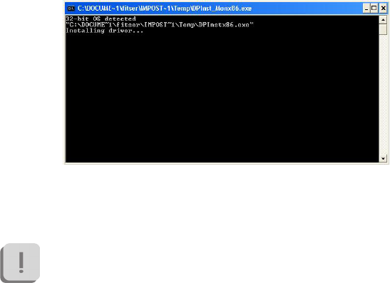
Hardware installation
e rst step of the hardware installation procedure consist in the USB
receiver driver installation.
To do that enter in the CD player of the workstation, the BTS CD
software containing the installation les that contains the “EmbEMG-
X.X.XX.X.zip” le.
Extract the .zip le in the local disk C and then perform a double click on
the le “CDM20814_Setup.exe” and wait for the window that has just
opened, to close.
After have performed all the steps above, it will be necessary to congure
the port for the USB receiver.
To set the characteristics of the receiver the system requires the
receiver to be connected to the PC via a USB port.
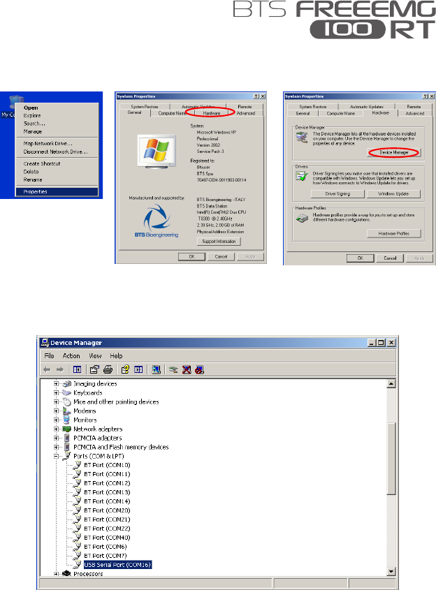
en, clicking the mouse right button on “My Computer”, select
“Properties”, choose “Hardware” and then enter the “Device Manager”:
35
BTS
Bioengineering
installation
Once inside the Device Manager menu, select “Ports (COM & LPT)” and
click the right button on the item below “USB Serial Port (COMx)” and
select “Properties”.
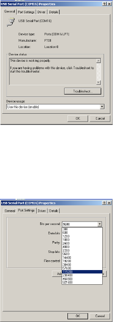
Entering the port properties window it will be displayed the following:
36
BTS
Bioengineering
installation
In which you must select the TAB “Port Settings”.
From this TAB set in the drop box menu related to the “Bits per second”,
the value 115200 and then click “Advanced”.
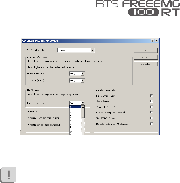
In the window that opens, you must set the value of “Latency Timer
(msec)” equal to 1msec, and then click “OK”, returning to the previous
screen.
37
BTS
Bioengineering
installation
Also in the “Port Settings” window click on “OK” then close the windows
remained still open.
During the setting operations of the COM port, take note of the
port number that the PC automatically associates to the device,
because you will need it at the software rst start.
Description of the software on the user PC
BTS EMG-Analyzer is the complete and highly exible solution for
making advanced elaborations of electromyographic signals and angular
measurements of body segments.
Includes predened templates for evaluations in clinics, sports, and
research and an editor to develop customized elaboration protocols.
38
BTS
Bioengineering
installation
In the following paragraph we will refer to this software, however BTS
FREEEMG 100 RT is manageable also by BTS MIOFEED software and
all BTS applications of SMART family dedicated to the motion analysis.
For more details concerning the use of BTS FREEEMG 100 RT
with other software, please refer to its specic manual.
Before to proceed verify that the software BTS EMG-Analyzer has
been properly installed on the user PC (please refer to its manual
for the installation procedure).
BTS EMG-Analyzer conguration check
Keeping the receiver still inserted in the USB port, launch BTS EMG-
Analyzer double-clicking on the relative icon.
If the following windows appears:
Click on “OK” to reach the software main screen.
On the menu bar at the voice “Laboratory” select “Set Emg Device”.
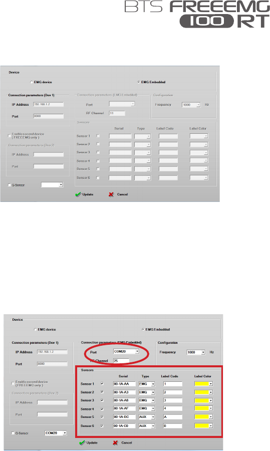
e following windows will open:
39
BTS
Bioengineering
installation
Verify that the check is on “EMG embedded”.
Select the correct Port number acting on the drop box menu, according
with the port number that the PC has automatically associated to the device
during the COM port setting operations (see §”Hardware installation”).
If the port number selected is the correct one the software will activate the
Sensors area of the windows and all the info about the sensors associated
with the USB receiver connected to the workstation will be visualized.

40
BTS
Bioengineering
installation
Verify that all the parameters values coincide with those reported on the
supplied sensors that you want to use (see § “Wireless EMG probes” and
“Wireless EGN/FSW probes”).
During the acquisition the system will acquire always all the
sensors enable in this windows. Is possible to disable the sensors
that you don’t need for the acquisition. Click on “Update” before
closing the window to save the new conguration.
To enable a sensor click on the white square correspondent, the check
mark will appear and then ll the elds “Serial”, “Label Code” and “Label
Color”, according with the value reported on the probes (see § “Wireless
EMG probes” and “Wireless EGN/FSW probes”), and select a “Type”
between “EMG” and “AUX”.
Click on “Update” before closing the window to save the new conguration.
41
BTS
Bioengineering
Now we will describe a basic procedure about how to create a new protocol
using BTS EMG-Analyzer software.
Refer to the EMG-Analyzer manual for further details about the
“Protocol builder” function.
e procedure may be dierent if performed with other
applications. In this case, refer to the specic manual of the
software you are using.
Please note that with BTS FREEEMG 100 RT it is possible to acquire up
to 6 probes.
Refer to § “Receiving unit” for the details about possible probe
combinations.
Launch the software EMG-Analyzer.
Before to proceed we suggest you to make the procedure described
in the § “Software conguration check” to be sure to have selected
the EMG embedded device and to have enabled all the probes
required for the acquisition.
To create a new protocol, from the menu voice “Laboratory” of BTS
EMG-Analyzer, select “Create Emg Protocol” .
acquisition protocol
42
BTS
Bioengineering
acquisition protocol
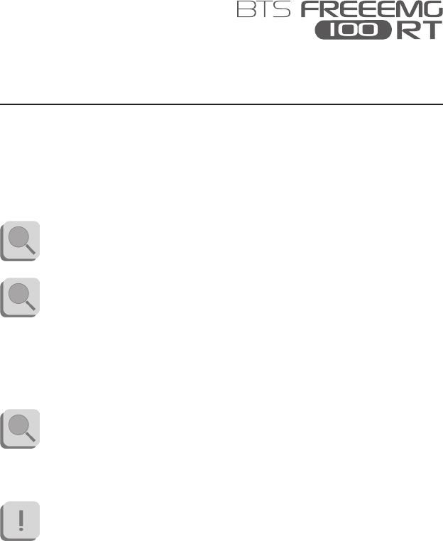
e window for the creation or modication of protocols will open.
If the receiver is connected to the PC and correctly set, in the rst column of
the protocol table there will be reported the labels of the probes connected
to the receiver, and the active protocol will be displayed.
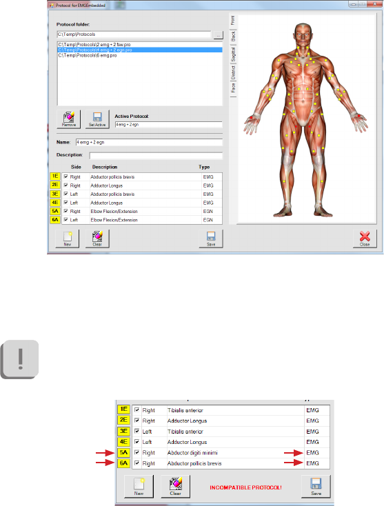
If the active protocol is not consistent with the set of probes
connected to the receiver the following warning message will be
displayed on the bottom part of the windows:

43
BTS
Bioengineering
acquisition protocol
To proceed with the acquisitions it is necessary to have the probes
set and the selected protocol compatible.
To reach this condition it is possible:
- to select a line of the protocol and modify any elds to make
it consistent with the probes set,
- to select an other protocol compatible with the probes set
among the ones saved in the database and displayed in the
“Protocol folder” area of this windows, and set it as “Active
protocol” clicking on “Set Active”,
- coming back to the “Set Emg Device” windows and modify
the probes set.
To create a new protocol follow this procedure:
- click on “New”. e elds to be lled for the protocol creation will
be enabled.
- select the anatomical map containing the muscle you want to add to
the protocol and click on the little yellow square that identied it;
immediately the rst free row available in the protocol table will be
lled with the info related to the selected muscle.
- repeat this operation for all the muscles to be acquired.
- if you want to acquire Footswitches, rst of all verify that there were
no EGN already selected in the protocols, otherwise the protocol
won’t be valid and the software won’t allow saving it.
Select the “District” anatomical map and proceed click on the right
and then on the left foot by selecting the corresponding square in the
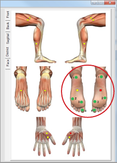
44
BTS
Bioengineering
acquisition protocol
anatomical map:
- If you want to acquire Electrogoniometers, rst of all verify that there
were no FSW already selected in the protocols, otherwise the protocol
won’t be valid and the software won’t allow saving it.
Check the rst free line in the protocol table, click on the “Type” eld
and select EGN among the voices available in the drop box menu.
In the same way, click on the “Description” eld and select among the
drop box menu voices the angles you want to acquire with the EGN,
then on the “Side” eld to select the body side to which the data refers.
- indicate a name for the protocol specifying it on the “Name” box.
-it is possible to insert also a short description of the protocol using the
appropriate box “Description”.
When every signal of the protocol has been inserted, proceed saving the
45
BTS
Bioengineering
acquisition protocol
protocol, clicking on “Save”.
If the protocol is compatible with the probes combination allowed by the
system the protocol could be saved.
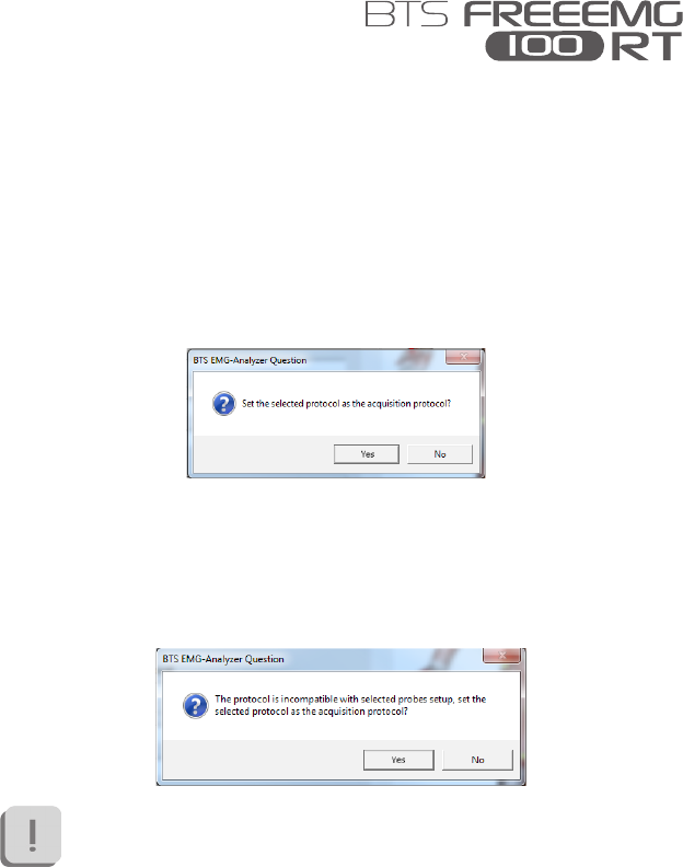
If the Probes setup is compatible with the protocol the following windows
will be displayed:
Clicking on “Yes” it will be set as “Active protocol” and will be used in the
next acquisition session.
Instead if the Probes setup is not compatible with the protocol the message
displayed will be:
To proceed with the acquisition it is necessary make the probes set
and “Active protocol” consistent.
In both cases clicking on “NO” the protocol will be saved in the “Protocol
Folder” and will be available in the future, but the “Active protocol” won’t
be modied.

47
BTS
Bioengineering
Wireless Probes
Geometry: variable
Electrodes: standard with clip connection
Separation: min: 16mm - max: 66mm
Autonomy: 8h of use
some days stand-by
some months deep sleep
Battery: rechargeable, lithium ion
Dimensions: 14x41,5x24,8mm mother electrode
diameter 16x12mm satellite electrode
Weight: 13g battery included
Frequency used: ISM band
2.4GHz (standard IEEE802.15.4)
Input impedance: >10 GOhm
CMMR: >110 dB @ 50-60Hz
Resolution: 16bit
Acquisition frequency: 1KHz
Sensitivity: 1μV
Accuratezza di misura*: ± 2%
Receiving Unit
Connection: USB
Dimensions: 82x44x22,5mm
Weight: 80 gr
appendix A
technical specications

48
BTS
Bioengineering
appendix
Frequency used: ISM band
2.4GHz (standard IEEE802.15.4)
* e system is calibrated at the factory. No further calibration is required
BTS internal coding
Name of device, components, parts and/or
accessories as per product label
Identier for
device (bar code,
catalogue, model or
part number)
FREEEMG 100 RT
USB receiving unit
EMG wireless probes FREEEMG 100 RT
FSW/EGN wireless probe
Foot switches: Insole individual foot switches for the
automatic identication of the gait events.
Electrogoniometers: Sensors for the measurement of
joint angles progress over the time.
FRESPU12
EMG-Analyzer: software application for EMG signal
analysis SMAN0901
Charger FRESPU06

49
BTS
Bioengineering
appendix B
environmental specications
Min Max Note
Operating Temperature -20° +45°
Operating Humidity 50% 80% Relative,
non-condensing
Storage and Transport
Temperature 0° +40°
Storage and Transport
Humidity 50% 80% Relative,
non-condensing
Altitude 0m 2000m
Degrees of protection provided by the dangerous enclosures of water and
dust (IEC 60529): IPX0.

50
BTS
Bioengineering
appendix C
power supply and switch o
e receiving unit is powered by the USB port.
To switch o the system the following operation must be done:
- Exit from the application software
- Unplug the receiving unit from the USB port.
- Put the probes in “Deep Sleep Mode” placing them on the “Charger”.
51
BTS
Bioengineering
BTS FREEEMG 100 RT probes are internally powered.
e Probe battery replacement can be done only by BTS qualied
personnel.
e probes are sealed to avoid the access to the internal circuit
components.
Batteries are equipped with battery protection circuit to:
-over-voltage, threshold 4.3V
-under-voltage, threshold 2.8V
- short-circuits
e specic characteristic of the Wireless probes equipped with the battery
are:
Quantity: 1 per each EMG probe
Technology: lithium polymer (Li-Poly)
Removable: NO, BTS technical service is required
appendix D
battery
52
BTS
Bioengineering
appendix E
troubleshooting guide
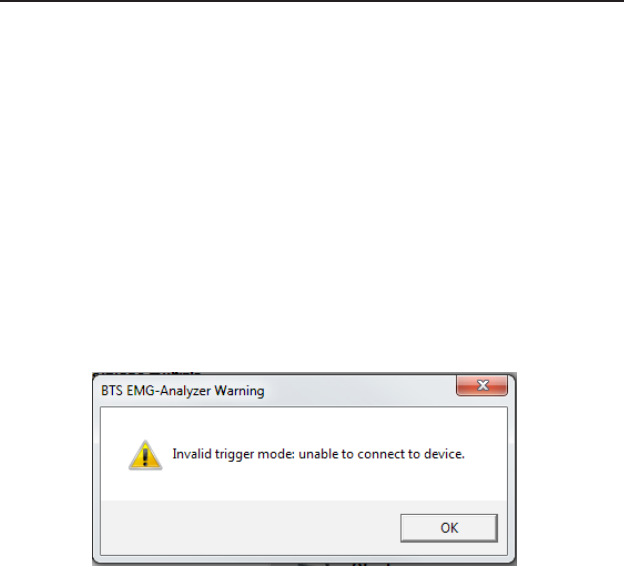
Warning – Invalid trigger mode
During the hardware installation, the USB port dedicated to the receiver,
is congured. May happen that these port settings went lost.
is event may occur for example when another USB device is connected
to the PC and the PC assigns to it the same port previously assigned to the
receiver, returning the port setting to the default conguration.
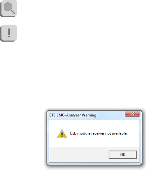
In these cases it may occur that by launching an acquisition the following
warning message may appear:
In this case to proceed immediately with the acquisition, it is necessary
to restart the application, however the same problem will recur in later
acquisitions.
To resolve this problem you must repeat the USB port conguration
procedure described in the “Hardware Installation” paragraph of the
“Installation” chapter.
53
BTS
Bioengineering
appendix E
declartion of conformity
DECLARATION OF CONFORMITY
BTS SpA
Via della Croce Rossa 11, 35129 Padova (PD) – Italy
Tel. +39 049 981 5500 Fax +39 049 792 9260
declare under our sole responsibility that the product(s):
name / description: Electromyographic system / device for recording myoelectrical activity.
model: FreeEMG 100 RT
S/N: SN
satisfies the essential requirements of the Medical Devices Directive 93/42/EC (and its amendments inluding
2007/47/CE), and therefore carries the CE marking of the European Union. The conformity assessment procedure is
according to the article 11 of the directive (Annex II.3 full quality assurance) and the article 12 it is not applicable.
In accordance with Annex IX of the 93/42/EC directive it is classified as follow:
CLASS “IIa” (rule 10)
In accordance with IEC 60601-1 is also classified as follow:
Class: internally powered device Applied part type: BF
The product conforms to the following standards:
EN ISO 14971 Medical Devices - Application of risk management to medical devices.
IEC 60601-1 Medical Electrical Equipment - Part 1: General Requirements for basic safety and
essential performance.
IEC 60601-1-2 Medical Electrical Equipment - Part 1-2: General requirements for basic safety and
essential performance - Collateral standard: electromagnetic compatibility -
Requirements and tests.
IEC 60601-1-6 Medical Electrical Equipment - Part 1-6: General Requirements for basic safety and
essential performance - collateral Standard: Usability
EN 62304 Medical device software - Software life-cycle processes
ETSI EN 301 489-3 Electromagnetic compatibility and Radio spectrum Matters (ERM) – Electromagnetic
Compatibility (EMC) – standard for radio equipment and services – Part 3: Specific
conditions for Short-Range Devices (SRD) operating on frequencies between 9 KHz and
40 GHz.
ETSI EN 301 440-2 Electromagnetic compatibility and Radio spectrum Matters (ERM) – Short Range Devices
(SRD) – Radio equipment to be used in the 1 GHz to 40 GHz frequency range – Part 2:
Harmonized EN covering essential requirements of Article 3(2) of the R&TTE Directive.
This compliance is valid ONLY for the equipment identified when used in a manner consistent
with the intent of the referenced documents and according to the product’s usage manual.
Notified Body : TÜV Product Service GmbH, Zertifizierstelle, Ridierstrasse 65, 80339 München – Germa-
ny, Identification N. 0123.
EC certificate N. G1 12 10 65301 003 valid until January, 16 2018.
Padova, Date
Bruno Ros
CEO
BTS S.p.A.

54
BTS
Bioengineering
FDA Medical Device Reporting System—Reportable Events
Notice to Agents: for inclusion in all BTS systems supplied to the
United States of America, the master Medical Device Reporting
(MDR) le is located at BTS S.p.A. Should an adverse event occur,
the following form is to be completed and forwarded within one
working day to BTS S.p.A.
Department of Health & Human Services,
US Food and Drug Administration
Medical Device Reporting System—Reportable Events
Code of Federal Regulations
Title 21, Volume 8
Revised as of April 1, 2006
Cite: 21CFG803.32
Under 803.1(a) device user facilities and manufacturers must report
deaths and serious injuries to which a device has or may have caused or
contributed. Should such an event occur, please complete the following
details and forward the document in accordance with the applicable
regulations and time limits to one of the following addresses:
BTS S.p.A.
via della Croce Rossa 11
35129 Padova PD - Italy
tel +39 049 981 5500
fax +39 049 792 9260
appendix G
regulatory notice
55
BTS
Bioengineering
appendix
Adverse Event Report (21 CFR 803.32)
Use blank pages if required.
Section A. Patient Information
Patient condentiality to be maintained unless authorized
otherwise in writing by User Facility.
Patient name or other identier
Age at the time of the event (Years, Months),
or Date of birth (MM/DD/YYYY)
Gender Female Male
Weight lb kg
Section B. Adverse Event or Product Problem
Identication of adverse event or product problem
(check all that apply) Adverse Event
Product Use Error
Product Problem (e.g. defects/malfunctions)
Problem with Dierent Manufacturer of Same System
56
BTS
Bioengineering
appendix
Outcomes attributed to the adverse event
(check all that apply) Death:
(MM/DD/YYYY)
Life-threatening injury or illness
Hospitalization—initial or prolonged
Required intervention to prevent permanent
impairment/ damage (Devices)
Disability or permanent damage:
Congenital Anomaly/Birth Defect
Other Serious (Important Medical Events)
Date of Event
(MM/DD/YYYY)
Date of this report
(MM/DD/YYYY)
Describe event, problem or product use error
(include a discussion of how the device was involved, nature of the
problem, patient follow-up or required treatment, and any environmental
conditions that may have inuenced the event)

57
BTS
Bioengineering
appendix
Relevant tests/laboratory data, including dates
Other relevant history, including preexisting medical conditions
(e.g. allergies, race, pregnancy, smoking and alcohol use, liver/kidney
problems, etc.)
Section C. Device Information
Brand Name
Type of Device
Manufacturer name
and address
Model # Lot #
Catalog # Expiration Date
(MM/DD/YYYY)
Serial # Other #
58
BTS
Bioengineering
appendix
Operator of the device
(delete not applicable)
health professional
patient
lay user
other:
(specify)
Date of system installation
(MM/DD/YYYY)
Device available for
evaluation?
(Do not send to FDA)
yes
no
Returned to BTS S.p.A.
or its agents on:
(MM/DD/YYYY)
Concomitant medical products and therapy dates
(do not report products that were used to treat the event)
59
BTS
Bioengineering
appendix
Section D. Initial Reporter Information
For the reporter who initially provided information to you, or to the
manufacturer or distributor:
Name
Address
Telephone Number
E-mail Address
Health Professional? Yes
No
Occupation (include
speciality if appropriate)
Initial reporter also sent a
copy of report to FDA?
Yes
No
60
BTS
Bioengineering
appendix
Section E. User Facility Information
Health Professional? User Facility
Importer
User Facility Number
User Facility Name
User Facility Address
Contact Person
Phone Number
Date User Facility became
aware of event (MM/DD/YYYY)
Type of Report Initial
Follow-up #
Date of this Report
(MM/DD/YYYY)
Approximate age of system
Event problem Codes (refer to “MED-
WATCH Medical Device Reporting
Code Instructions”)
Report sent to FDA? Yes
(MM/DD/YYYY)
No
Report sent to
manufacturer?
Yes
(MM/DD/YYYY)
No
61
BTS
Bioengineering
appendix
Location where event
occurred
Hospital
Home
Nursing Home
Outpatient Treatment Facility
Outpatient Diagnostic Facility
Ambulatory Surgical Facility
other:
(specify)
Manufacturer Name/Address

BTS Bioengineering Corp.
147 Prince Street - Suite 11
11201 Brooklyn NY
USA
info: +1 347 204 7027
helpdesk: +1 646 575 0426
BTS S.p.A.
viale Forlanini 40
20024 Garbagnate M.se MI
Italy
tel +39 02 366 490 00
fax +39 02 366 490 24
www.btsbioengineering.com
info@btsbioengineering.com