BTS BTSWEMG2 Wireless EMG sensor for EMG system User Manual ERTMJ 00998 04 TMJOINT ENG v 3 0 0
BTS SpA Wireless EMG sensor for EMG system ERTMJ 00998 04 TMJOINT ENG v 3 0 0
BTS >
Contents
- 1. EREMB-01091-06 FREEEMG 100 RT User Manual ENG v.2.0.3
- 2. ERFNC-00782-16 FREEEMG 300 User Manual ENG v.4.0.3
- 3. ERTMJ-00998-04 TMJOINT User Manual ENG v.3.0.0
ERTMJ-00998-04 TMJOINT User Manual ENG v.3.0.0
version 3.0.0
user manual
english
BTS TMJOINT
Document Number : ERTMJ-00998-04
Published: January 2013
Copyright © 2010 - 2013 BTS SpA. All Rights Reserved.

1
BTS
Biomedical
BTS TMJOINT
contents 1
icons, symbols and acronyms 5
radio regulation 9
disposal (WEEE) 10
intended use 11
regulatory label 12
receiving unit regulatory label 12
EMG wireless probes regulatory label 12
charger regulatory label 13
warnings 14
copyright 17
introduction 18
general description 18
case contents 20
system components 22
receiving unit 22
wireless EMG probes 23
charger 26
installation 28
user PC minimum conguration 28
connections 28
description of the software on the user PC 29
software installation 29
hardware installation 31
rst software use 34
contents
2
BTS
Biomedical
BTS TMJOINT
contents
patient setup 37
POC4 protocol 37
POC6 protocol 39
guide to the use of BTS DCA 41
initial screen 41
menu bar 42
tool bar 47
probes status bar 47
patient list and research lter 49
patient, session and trial information 52
trial viewing and report generation area 53
main features of the BTS DCA software 59
new patient 59
new session 59
edit pathology 62
new trial 63
data acquisition 66
edit patient 72
edit session 73
delete patient 74
delete session 75
delete trial 76
more features of the BTS DCA software 77
database and data folder 77
managing les in the recycle bin 80
guide to of the data report reading 83
INT tab 83
EXT tab 89
POC tab 94
3
BTS
Biomedical
BTS TMJOINT
contents
ISTO tab 96
MAST tab 98
INFO tab 100
appendix A – technical specications 103
wireless probes 103
receiving unit 103
appendix B – environmental specications 105
appendix C – power supply and switch o 106
appendix D – battery 107
appendix E – troubleshooting guide 108
warning – invalid trigger mode 108
appendix F – declaration of conformity 109
appendix G– bibliography 110
5
BTS
Biomedical
BTS TMJOINT
icons, symbols and acronyms
Symbol in the instructions for the function.
e icon represents the information which requires special attention.
Symbol in the instructions for the function.
is icon makes reference to a more detailed discussion of the subject in
hand.
Symbol on the equipment:
e data appearing next to the manufacturer’s symbol refer to the place of
manufacture of the equipment itself.
Symbol on the equipment:
e “FCC” simbol refers to the Federal Communication Commission of
the USA. e device complies with the relevant regulations put forth by
the FCC as long as it is operated according to the instructions contained
in this manual and to all national and local regulations.
6
BTS
Biomedical
BTS TMJOINT
icons, symbols and acronyms
Symbol on the equipment:
e gure in the square indicates the insulation class and the part types
used. In accordance with Standard ISO 60601-1, the equipment has an
internal power supply and the parts used are type BF.
Symbol on the equipment:
Attention, read the information in the users’ manual carefully before using
the equipment.
Symbol on the equipment:
e double square indicates that the product is a medical device of II
Class (In accordance with the law EN 60601-1).
Symbol on the equipment:
CE mark with the code of the Notied Body. e CE mark certies that
the product conforms to the standards applicable in the member states of

7
BTS
Biomedical
BTS TMJOINT
icons, symbols and acronyms
the European Union (see Declaration of Conformity).
Symbol on the equipment:
CE mark with the code of the Notied Body. e CE mark certies
that the product conforms to the Directive 99/05/EEC - R&TTE and
obtained the Expert Opinion by IMQ.
Symbol on the equipment and in the users’ instructions:
Symbol for the separate disposal of electrical and electronic equipment, in
accordance with Directive 2002/96/CE (WEEE).
e equipment belongs to Group 8 (medical equipment).
In force in the nations of the European Union, Norway and Switzerland.
Rx only
Symbol for prescription only. U.S. Federal law restricts this device to sale
by or on the order of a physician or properly licensed practitioner.

8
BTS
Biomedical
BTS TMJOINT
icons, symbols and acronyms
REF
Symbol on the equipment:
Symbol located next to the model number (ref.to catalogue).
SN
Symbol on the equipment:
Symbol located next to the series number on the equipment.
Acronyms used in this manual:
RU Receiving Unit
EMG Electromyography
WS Workstation
DCA Dental Contact Analyzer
POC Percent Overlapping Coecent
MVC Maximum Voluntary Contraction

9
BTS
Biomedical
BTS TMJOINT
radio regulation
Radio equipment identication:
- EMG probes:
FCC ID: YQH-BTSWEMG2
IC: 9188A-BTSWEMG2
- receiving Unit contains:
FCC ID: TFB-MATRIXLP
IC: 5969A-MATRIXLP
is device complies with part 15 of the FCC Rules. Operation
is subject to the following two conditions: (1) is device may
not cause harmful interference, and (2) this device must accept
any interference received, including interference that may cause
undesired operation.
Modications not expressly approved by BTS SpA could void the
user’s authority to operate the equipment under FCC rules.
10
BTS
Biomedical
BTS TMJOINT
disposal (WEEE)
In disposing of the equipment observe the legal prescriptions.
In accordance with Directive 2002/96/CE (WEEE) all equipment supplied
after 13/08/2005 may not be disposed of in general domestic waste. is
equipment belongs to Category 8 (medical equipment) and is classied in
the Business-to-Business sector.
e symbol of the crossed out rubbish bin
indicates that the equipment must not be
disposed of in normal domestic waste.
e regulations for disposal may dier between
individual countries in the EU. In cases of doubt,
refer to the respective sales outlet.
is is a battery-powered equipment.
See Appendix D for information about the batteries used. Operate
and dispose of this equipment according to the instructions set in
the “warnings” section.

11
BTS
Biomedical
BTS TMJOINT
intended use
is equipment is an instrument for the EMG surface analysis, classied
as medical equipment in accordance with European Directive 93/42/CE
(and its amendments).
BTS TMJOINT must always be used only for this purpose, by qualied
persons, in an environment suitable for the execution of EMG analyses
and respecting the prevailing regulations in the countries in which it is
being utilised.
12
BTS
Biomedical
BTS TMJOINT
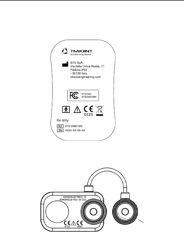
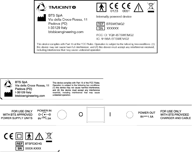
regulatory label
Probe ID
Receiving Unit Regulatory label
EMG Wireless Probes Regulatory label
Label on the probes:
13
BTS
Biomedical
BTS TMJOINT
regulatory label
Label not on actual probes due to size constraints:
Charger Regulatory label

14
BTS
Biomedical
BTS TMJOINT
We recommend to carry out any kind of operation keeping strictly
to the security regulations contained in this manual.
TMJOINT is a medical device (EU Directive 93/42/CE and its
amendments, including Directive 2007/47/CE) which use must be at all
times be supervised by qualied and authorized personnel, according to
the laws in force in the nation it is in use. e EMG probes are classied as
ETSI EN 300 440 “Receiver category 3” according to Directive R&TTE
99/5/EEC.
e results of the acquisitions must be assessed by people legally authorised
by national law, who possess the suitable necessary knowledge of anatomy
and muscular function.
e uses of the device for other purposes and with methodologies dierent
from of those indicated in this manual are not to be considered congruent
with the precise use of the device.
- Use the product according to the usage that it has been intended.
- Avoid connecting the probes to the charger with inverted polarity
with respect to that shown on the cover of the recharger - this
could cause irreparable damage to them.
- To not wet or dip in water the parts that make up the system.
warnings
15
BTS
Biomedical
BTS TMJOINT
warnings
- Apply the probes only on undamaged skin.
- Only use CE branded probes and hypoallergenic double-sided
tape, compatible with the usage on undamaged skin for brief
periods of time.
- Periodically verify the integrity of the system and of its components.
- In case the device accidentally falls, tear of the probes or other
accidents always address authorized technical support.
- Do not undertake any kind of internal maintenance of the device:
in case of need always address to authorized technical support.
- e use of any components dierent from the original ones
declines the conformity of the device.
- e instrument must be used in a medical environment, since it
has a high level of sensitivity (measured voltage levels of between
1 microvolt and 6 millivolt).
- In addition to the users’ instructions, the prescriptions regarding
accident prevention and technical regulations regarding
occupational safety must also be complied with.
e appertaining national regulations and standards of the country
of use, with regards prevention of accidents and environment, are
an extension of the users’ instructions.
- TMJOINT is a device that is able to function CONTINUOUSLY,

16
BTS
Biomedical
BTS TMJOINT
warnings
this is of course limited by the battery duration and by the
memory available for the acquisition data storing.
- the device uses lithium ion battery. For the battery replacement
and disposal please contact the technical support. At any rate,
ensure that device component (i.e. probes, receiving unit,...)
integrity is never compromised.
e information contained in this manual is subject to change
without notice and does not constitute product specications or
any obligation on the part of BTS S.p.A.

17
BTS
Biomedical
BTS TMJOINT
copyright
e software of the system described in this manual is supplied with the
“licence to use” contract. e software may be used or copied only as
stipulated under the terms of this contract.
No part of this manual may be copied or transmitted in any form or
means, electronic or mechanical, including photocopying, without prior
written permission from BTS S.p.A.
Unless otherwise specied, any reference to companies, names, data and
addresses used in the reproduction of the screens and the examples are
purely incidental, and has the sole purpose of illustrating the use of the
BTS product. All trademarks are registered by the respective owners.
is publication contains reserved information which is the
property of BTS S.p.A.
e recipient acknowledges that the illustrations and information
supplied in this manual shall not be made available to third parties
without explicit written agreement by BTS S.p.A.

18
BTS
Biomedical
BTS TMJOINT
General description
BTS TMJOINT is the solution for the functional analysis of dental
occlusion. Functional information is provided on the neuromuscular
alterations induced by occlusal contact.
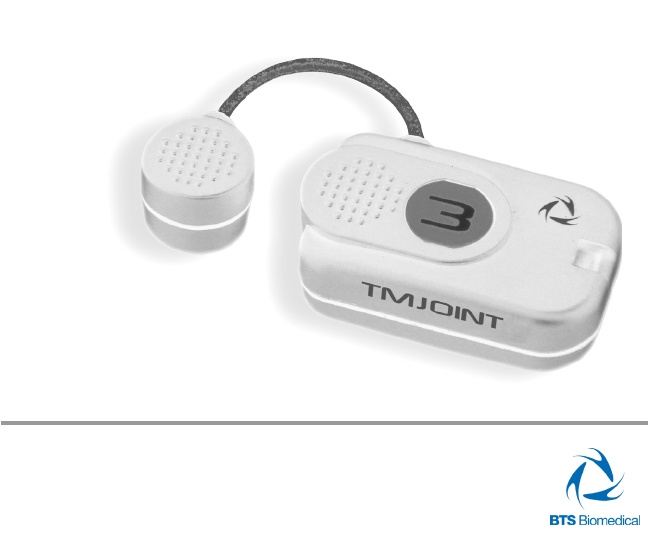
BTS TMJOINT integrates the latest wireless technology available today.
Based on wireless technology, this solution includes a set of EMG probes
with active electrodes, the only one of its kind in the world due to its
light weight (weighing less than 9 grams), compact size and data capturing
accuracy, a USB receiving unit and the dedicated software BTS Dental
Contact Analyzer.
BTS TMJOINT uses surface electromyographic analysis to measure the
dierential inuence of the occlusal function through indices validated
and published in scientic literature.
Special feature of this system is the standardization of the electromyographic
signal that is provided by the comparison between two test of clenching,
done with and without the interposition of cotton rolls between the
dental arches. is method allows the elimination of problems of the
wrong positioning of the electrodes, of the dierence of impedance of
the patient’s skin, of the dierences of muscular tropism, etc. making it
accurate and repeatable.
e results are shown via a special graphic interface that is easy to
introduction
19
BTS
Biomedical
BTS TMJOINT
introduction
understand for both the physician and patient.
e specialized software BTS Dental Contact Analyzer, provide, indeed,
the automatic indices calculation, plotted in a table form, with pie charts
and histograms.
BTS TMJOINT is a modular and scalable solution, structured on various
levels of analysis.
e rst level, called POC4, includes 4 capture probes and the analysis
protocol. rough a quick 5 second clenching test, the activities of the
masseter and anterior temporal muscles, right and left, provide, as an
immediate result, a POC percentage overlapping coecient (an index
of the symmetric distribution of the muscular activity determined by
the occlusion) and a TORS torque coecient (to estimate the possible
presence of mandibular torque), which makes it possible to establish the
role of occlusion on muscular balance.
A third index, called IMPACT, allows to evaluate the muscular work,
providing information about the occlusal vertical dimension.
e second level, called POC6, adds to the previous 2 capture probes for
calculating the indices related to the sternocleidomastoid muscle, right and
left. e eects of the teeth touching, on the neck muscles are evaluated.
e third level, called MASTICATION, analyses the neuromuscular
coordination during mastication. e masticatory frequency, the Lissajous
curve, and indices of muscle symmetry are calculated.
20
BTS
Biomedical
BTS TMJOINT
introduction
Case contents
• Receiving Unit
• Probes Kit available in 2 versions:
• POC4: include 4 wireless probes*
• POC6: include 6 wireless probes*
*(identicative labels available in 4 dierent colors)
• Probes Charger (AC adapter included)

21
BTS
Biomedical
BTS TMJOINT
introduction
• Set of disposable electrodes
• USB extension cable
• User manual
You will receive the instructions for use for other possible optional
components not mentioned in this manual.
22
BTS
Biomedical
BTS TMJOINT
6
8
4
2
5
3
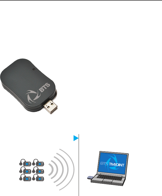
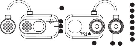
BTS TMJOINT system consists of two parts: the receiving unit and the
wireless EMG probes.
Receiving unit
e receiving unit, connected to the PC trough USB, allows the WiFi
reception of the EMG signal acquired by the wireless probes
WiFi transmission
system components
7
23
BTS
Biomedical
BTS TMJOINT
system components
Wireless EMG Probes
BTS FREEEMG 300 utilises miniaturized probes with active electrodes
weighing less than 13 grams.
e special design ensures maximum space-saving and comfort for the
patient who is free to move around without obstacles.
e probes can be hooked on directly to the pre-gelled electrodes without
requiring additional xing with plasters or double-sided tape.
is together with the total absence of cables enables a much faster patient
preparation, drastically reducing the time of each session.
Each probe consists of a mother electrode and a satellite electrode, each
tted with a clip. e two parts, connected via a exible cable, may be
positioned as needed by the user at adjustable distance (electrodes with
variable geometry).
All probes are also equipped with a solid state memory buer, to prevent
data loss for problems due to the WiFi network or due to exceeding the
useful operating range.
Each probe is tted with a LED indicating its state.
e probes can be in one of a number of dierent states:
• Charge: steady blue LED.
1
2
3
4
5
mother electrode
LED
satellite electrode
mother electrode clip
satellite electrode clip
exible cable
probe ID
6
7
5
1
2
2
5
3
4
6
7
24
BTS
Biomedical
BTS TMJOINT
system components
During the recharging phase the steady blue LED is on.
is phase occurs when the probes are connected to the charger
turned on, and the charge level is less than 90%.
When the charge level reaches 90% the led turns OFF.
Since, by connecting a probe to the charger on, it enters in “Deep
Sleep” mode, even while charging the probe will be completely
passive and does not respond to any commands.
• Active-Scanning: white LED which cyclically lights for a few
seconds.
In this mode the probe is searching for the receiving unit.
At intervals of about 1 minutes it carries out a scan of the
frequencies of few seconds. During the scan the white LED
ashes quickly.
• Active-Connected: white LED which ashes slowly.
When the probe and the receiving unit establish a connection,
the white LED begins to pulse slowly: the probe is waiting for
commands.
If the connection is interrupted, the probe returns to “Active-
Scanning” mode and attempts to re-establish the connection
with the receiving unit.
• Active-Capturing: white LED which lights and goes out at
regular intervals.
During acquisition the white LED ashes at regular intervals of
approximately one second. At the conclusion of the acquisition,
the probe returns to the “Active-Connected” condition.
If during the acquisition, connection to the receiver unit is lost,

25
BTS
Biomedical
BTS TMJOINT
system components
the probe continues to acquire, storing the data locally for one
minute and at the same time scans the assigned channel trying
to reconnect to the receiving unit.
If after one minute the scan is unsuccessful, the probe returns
to the “Active-Scanning” condition interrupting the storage of
data.
• Completely discharged or in “Deep Sleep” mode: LED is o.
If the probe is completely discharged the LED does not display
any ashing cycle and is o.
e same happens when it is in “Deep Sleep” mode (except
during the recharging phase in witch the led is steady blue).
e probes in “Deep Sleep” mode do not perform any
scan cycle, but are turned o. Is therefore guaranteed
energy savings.
To put the probe in “Deep Sleep” mode it is necessary to connect
them to the Charger switched on, or to put them in contact
with a magnet for half a second.
Before the next use is necessary to reactivate the probes,
putting them in contact with a magnet.
e probes are charged by a dedicated charger to which the probes are
connected via their respective clips.
For more info about the probes charge sse the paragraph “Charger”
of this chapter.
26
BTS
Biomedical
BTS TMJOINT
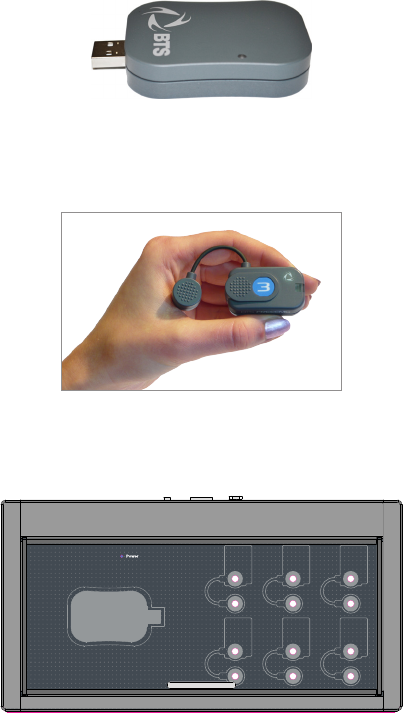
system components
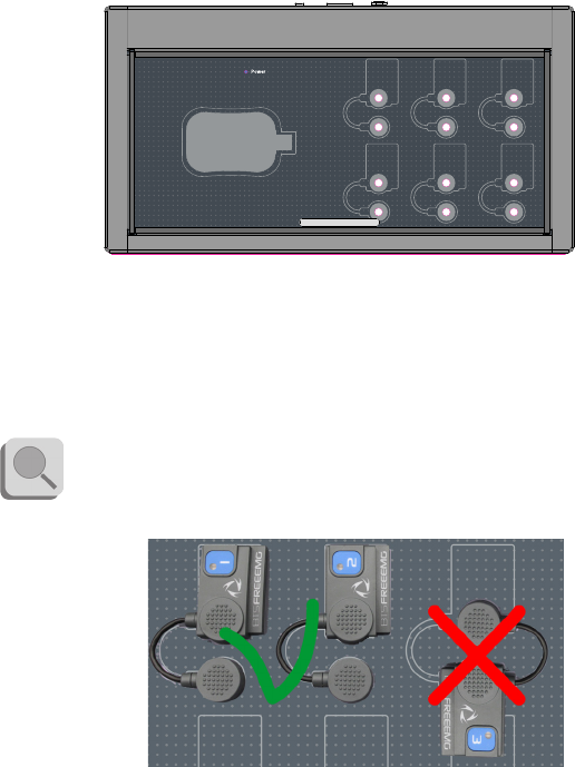
Charger
e Charger, included with the product, charges the BTS TMJOINT
probes.
e Charger can simultaneously charge all the EMG probes of the system
(6 maximum) and includes a lodging to store the receiver when not in use
for acquisition.
e EMG probes are connected to the charger using the same clips that
normally collect the EMG signal.
For correct connection simply follow the outline of the probes
shown on the base of the Charger.
At any rate, poles connected incorrectly will not recharge.

27
BTS
Biomedical
BTS TMJOINT
system components
In any case, the Charger comes with an output short circuit
protection system also in case of reversed recharging poles.
To recharge connect all the probes that you would like to charge to the
Charger (follow the instructions described above) and connect the AC/
DC adaptor to the mains and turn on the switch located on the rear panel.
When the Charger is properly connected to the mains and has been turned
on, the status LED “Power” will show a steady GREEN light.
e charging status of the probes is indicated by the status LED of the
probes (see § “Wireless Probes”).
Note that inserting the EMG probes into the Charger when it is
on, these come in “Deep Sleep” mode.
It is necessary to reactivate the probes, prior to use them, using a
magnet.

28
BTS
Biomedical
BTS TMJOINT
User PC minimum conguration
Operating system Windows 7
Processor Intel Dual Core
RAM 2 GB
Video resolution 1280x800
Disk space 100 MB for the application,
not including storage for acquired data
USB 2.0
Connections
e wireless probes transmit in real-time the acquired data to the receiver
connected via USB to the Workstation.
Connect the receiver to the WS using the USB connector.
If the morphology of the WS does not allow direct connection of
the receiver, use the USB extension cable.
Also verify that the probes are fully charged and ready for use.
It is required that the probes are disconnected from the charger to
be recognized and activated by the system.
installation
29
BTS
Biomedical
BTS TMJOINT
installation
Description of the software on the user PC
BTS TMJOINT is provided with BTS DENTAL CONTACT ANALYZER
- DCA, the specialized software for the automatic calculation of indices
correlated to the occlusal contact and to the possible neuromuscular
alterations induced by it.
e software allows managing the patient database, organized with a tree
root with sessions, trials and subject data, esplorable through dierent
database queries.
e provided data are translated in graphical form for an easier
interpretation and plotted in a table form, with pie charts and histograms.
It is possible to create report of single trial or to compare two trials such as
a pre and a post treatment.
All the reports, once created, can be saved and reloaded in a second time.
Software installation
BTS DENTAL CONTACT ANALYZER software is usually pre-installed
and congured.
However, if it is necessary to perform again the installation just follow the
instructions below.
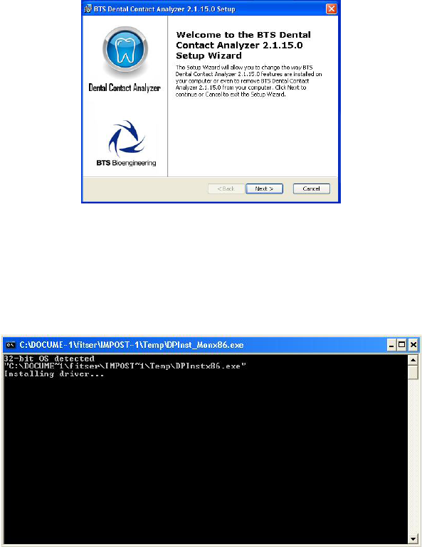
Once entered in the CD player of the computer dedicated, the BTS CD
software containing the installation les, launch the .exe le “POCAnalyzer-
X.X.XX.X.msi” and follow the instructions provided by the application.
It will appear the following screen:
30
BTS
Biomedical
BTS TMJOINT
installation
After have accepted the installation terms and chosen the Typical
installation, click always on “Next” key, until the procedure end.
en perform a double click on the “CDM20814_Setup.exe” le and wait
for the window that has just opened, to close.
31
BTS
Biomedical
BTS TMJOINT
installation
Check that on the PC are installed the following two elements:
• “Microsoft.NET Framework 3.5” (for Windows XP) or
“Microsoft.NET Framework 4” (for the next versions);
• “PDF Creator 1.2.1” (disable the research for possible
updates)
In case they are not already on your PC please download
them from the Internet (they are free) and install them.
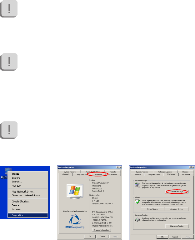
Hardware installation
After have performed all the steps above, it will be necessary to congure
the port for the USB receiver.
To set the characteristics of the receiver the system requires the
receiver to be connected to the PC via a USB port.
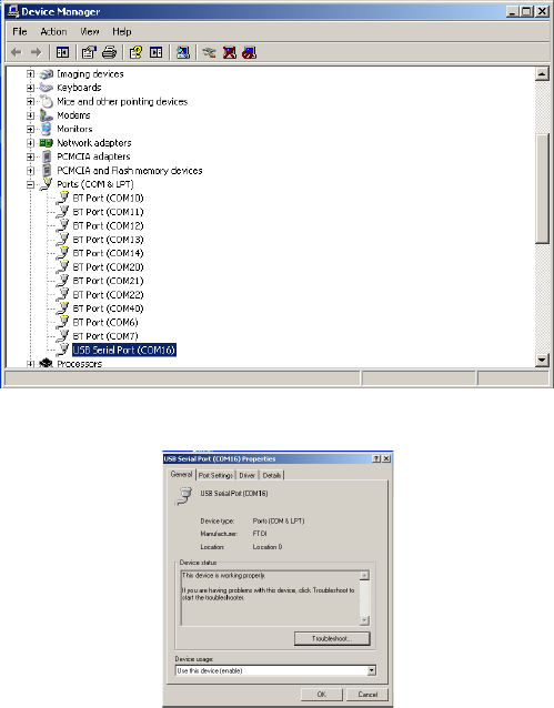
en, clicking the mouse right button on “My Computer”, select
“Properties”, choose “Hardware” and then enter the “Device Manager”:
32
BTS
Biomedical
BTS TMJOINT
installation
Once inside the Device Manager menu, select “Ports (COM & LPT)” and
click the right button on the item below “USB Serial Port (COMx)” and
select “Properties”.
Entering the port properties window it will be displayed the following:
In which you must select “Port Settings”.
33
BTS
Biomedical
BTS TMJOINT
installation
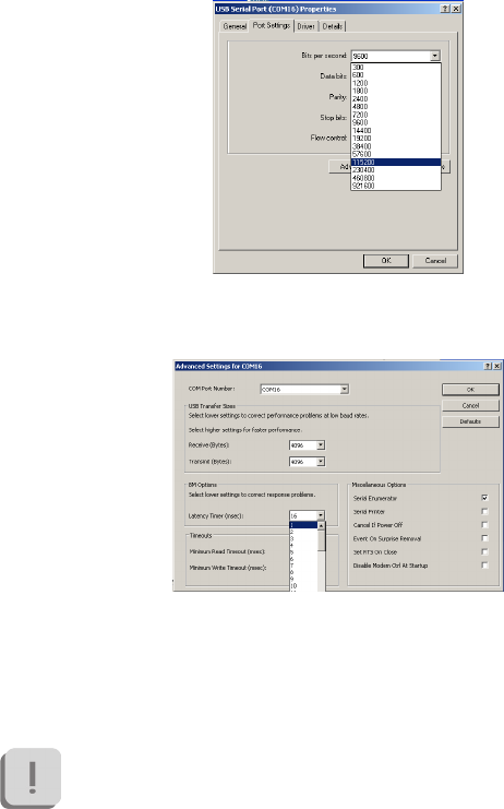
Set in the drop box menu related to the “Bits per second”, the value
115200 and then click “Advanced”.
In the window that opens, you must set the value of “Latency Timer
(msec)” equal to 1msec, and then click “OK”, returning to the previous
screen. Also in the “Port Settings” window click on “OK” then close the
windows remained still open.
During the setting operations of the COM port, take note of the
port number that the PC automatically associates to the device,
because you will need it at the software rst start..
34
BTS
Biomedical
BTS TMJOINT
installation
First software use
Continuing to keep the USB receiver into the USB input, double-click
the icon on your desktop “Dental Contact Analyzer” to run the software.
On the rst start it will be asked to choose the preferred language for the
interface software; once selected you must click on OK.
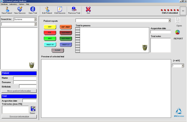
When the procedure will be completed, the software will start showing the
following window:
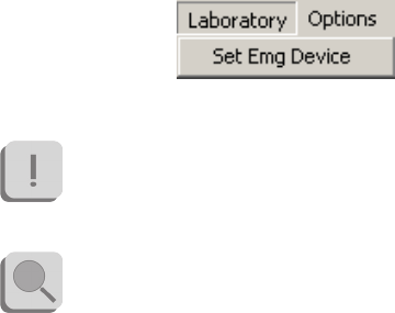
On the rst start you should check that the correct COM port is set by
selecting the “Laboratory” voice from the tool bar and click “ Set EMG
Device”.
35
BTS
Biomedical
BTS TMJOINT
installation
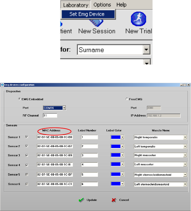
Clicking on the device settings, a new window will open.
Select the correct COM port number among the voices in the drop box
menu “Port”.

36
BTS
Biomedical
BTS TMJOINT
installation
If the chosen port is the one corresponding to the USB receiver
and if it is set correctly, the elds below will activate showing the
“MAC Address” of the probes associated with the receiver you are
using.
If all of these operations are successful, clicking on “Update” the window
will close and you can start using the software.
37
BTS
Biomedical
BTS TMJOINT
patient setup
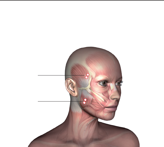
POC4 Protocol
e POC 4 protocol provides the acquisition of 4 muscles: the masseter
and the temporalis anterior bundle for both face sides.
Each probe is numbered and for this protocol we will use the probes from
1 to 4.
It is mandatory to follow this sequence:
• probe n. 1 – right anterior temporalis;
• probe n. 2 – left anterior temporalis;
• probe n. 3 – right masseter;
• probe n. 4 – left masseter.
Temporalis Anterior
Masseter

38
BTS
Biomedical
BTS TMJOINT
patient setup
For the RIGHT temporalis anterior bundle, touch the muscle during the
maximum clenching and nd the major axis of the zygomatic process of
the frontal bone; the electrode should be applied along a line parallel to
this axis that runs through a couple of centimeters posterior to the process
and above the temporal process of the zygomatic bone.
Repeat the procedure also with the LEFT temporalis anterior bundle,
trying to maintain a symmetry of positioning.
For the RIGHT masseter, position yourself behind the patient when
possible and touch the muscle during the maximum clenching, nding
its venter.
e electrode should be applied along the line that connects the external
canthus of the eye with the mandibular angle.
Repeat the procedure also with the LEFT masseter, trying to maintain a
symmetry of positioning.
It is recommended to apply in advance the probes on the pre-
gelled through the special clips, in order to avoid exerting pressure
directly on the subject face.
Before proceeding with the acquisition, verify that the chair’s
back is in vertical position. We ask to the subject to stay relaxed
with your legs uncrossed, hands resting on his knees and looking
forward.
39
BTS
Biomedical
BTS TMJOINT
patient setup
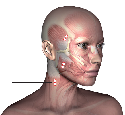
POC6 Protocol
e POC 4 protocol provides the acquisition of 6 muscles: will be acquired
also the sternocleidomastoid muscles, in addition to the masseters and the
temporalis anterior bundles analyzed in the POC 4 protocol.
We will use the probes from 1 to 6 following this sequence:
• probe n. 1 – right anterior temporalis;
• probe n. 2 – left anterior temporalis;
• probe n. 3 – right masseter;
• probe n. 4 – left masseter.
• probe n. 5 - right sternocleidomastoid;
• probe n. 6 - left sternocleidomastoid.
For the probes positioning on the masseters and temporal muscles, refers
Temporalis Anterior
Masseter
Sternocleidomastoid
40
BTS
Biomedical
BTS TMJOINT
patient setup
to the instructions in the previous paragraph.
To nd the RIGHT sternocleidomastoid, asks the subject to rotate, as
much as possible, the head to the left; the electrodes will be positioned on
the muscle so identied.
Repeat the procedure also with the LEFT sternocleidomastoid, trying to
maintain a symmetry of positioning.
41
BTS
Biomedical
BTS TMJOINT
guide to the use of BTS DCA
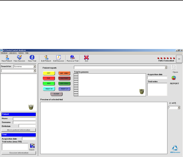
Initial screen
To launch the software DCA doubleclicking on the relative icon.
Once loaded the software the following windows will be loaded:
e windows includes the following main areas:
• the menu bar
• the tool bar
• the probe status bar
• the list of patients in the database provided with a search lter
• the information related to the patient, session or trial selected from
the list
• the area which manages the trial viewing and the report generation.
42
BTS
Biomedical
BTS TMJOINT
guide to the use of BTS DCA
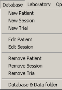
Menu bar
The menu bar contains:
• The “Database” menu which manages all the operations associated
with the patient database;
• The “Laboratory” menu from which to congure the EMG devices
to use;
• e “Options” menu which allows setting the software languages and
the chart property;
• The “Help” menu which supplies the software version number.
The following functions can be accessed from the “Database” pop-down
menu:
• “New Patient” to add a new patient to the Database.
• “New Session” to add a session to the patient already inserted in
the Database.
• “New Trial” to capture or import trials to an existing session.
43
BTS
Biomedical
BTS TMJOINT
guide to the use of BTS DCA
• “Edit Patient” to modify the information about a patient.
• “Edit Session” to modify the information associated with a
session.
• “Remove Patient” to eliminate the selected from the database. A
conrmation is requested.
• “Remove Session” to eliminate the selected session. A
conrmation is requested;
• “Remove Trial” to eliminate the selected trial. A conrmation is
requested.
From the database menu by selecting the voice “Database & Data folder”
it is also possible to select an other Database or create a new one, modify
the data folder path and select an application to read reports in PDF
format.
e second menu of the menu bar is the “Laboratory” menu:
From this menu the voice “Set Emg Device” may be accessed:
BTS TMJOINT use an Embedded EMG device, for this reason
be sure that this option is selected.
e BTS Dental Contact Analyzer software can interface itself
also with the BTS FREEEMG systems for the data acquisition.
Anyway the procedure of use of DCA with these other devices is
not described in this manual.
44
BTS
Biomedical
BTS TMJOINT
guide to the use of BTS DCA
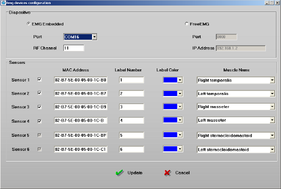
e following windows will be displayed:
is window is divided in two areas:
• the “Device” area containing the information related to the Port
and to the RF Channel for the data transmission;
• the “Sensors” area containing the information related to the 4 or
6 probes (depending on the version installed) and in particular for
each probes is indicated:
- the MAC Address containing the probe identicative code
printed on the clip of the same probe.
- the number indicated on the probe label
- the identicative color of the probe label
- the name of the muscle associated to that probe.
All these value can be modied by the user.
45
BTS
Biomedical
BTS TMJOINT
guide to the use of BTS DCA
If any change has been done, click on “Update” to make the changes
effective, while clicking on “Cancel” the values previously saved won’t be
changed.
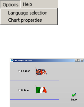
e next menu is the “Options” one:
From this menu the following functions may be accessed:
• “Language selection” to choose between Italian and English.
Select this command to call up the window in the gure:
Click on “Save” and restart the programme to make the changes
effective, or close this windows to come back to the previous
screen.
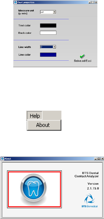
• “Chart properties” to set the visualization parameters of the
graphs of the acquired EMG signals and in particular the abscissa
unit of measure and the text, background and line color and the
line tight.
46
BTS
Biomedical
BTS TMJOINT
guide to the use of BTS DCA
From this menu voice the following windows may be accessed:
Click on “Save and Exit” to make the changes effective, or close
this windows to come back to the previous screen.
The last voice is the “Help” menu:
From this menu may be selected the voice “About” that supplies the
software version number:
47
BTS
Biomedical
BTS TMJOINT
guide to the use of BTS DCA
To close this windows and come back to the previous screen, just click on
the top right hand corner cross.
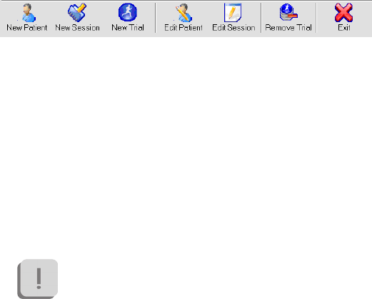
Tool bar
The tool bar provides rapid access to the most used functions:
• “New Patient” to insert a new patient in the Database.
• “New Session” to add a session to a patient already in the
Database.
• “New Trial” to manage the acquisition or import of a trial in an
existing session.
• “Edit Patient” to correct details about a patient.
• “Edit Session” to modify the information associated with a
session.
• “Remove Trial” to eliminate the selected trial. A conrmation is
required before proceeding with the operation.
The deleted trial is moved to the recycle bin.
• “Exit” to leave the programme.
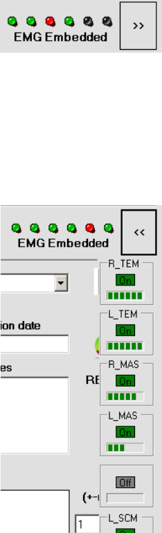
Probes status bar
e probes stratus bar, located in the top right hand area of the main
screen, allows knowing immediately at any time the connection status of
the 4 or 6 supplied probes.
48
BTS
Biomedical
BTS TMJOINT
guide to the use of BTS DCA
e LED can appear:
- blinking GREEN if the probe is active;
- blinking RED if the probe is not active;
- GRAY if the probe is not enabled.
It is also possible to know the active probes battery status by clicking on
the button marked by the symbol “>>”:
49
BTS
Biomedical
BTS TMJOINT
guide to the use of BTS DCA
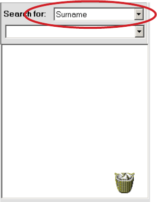
Patient list and research lter
On the left side of the screen there is the area to manage the patients
inserted in the database.
At the software startup, it appears empty:
By opening the drop box menu marked with the red ellipse, a list of all the
patients inserted in the Database will appear.
Each patient is identied by a surname, rst name and if available among
the patient data, by his or her internal code.
The patients are ordered, according to the alphanumeric characters,
respect the eld indicated in the drop box menu “Search for”, in the
50
BTS
Biomedical
BTS TMJOINT
guide to the use of BTS DCA
example “Surname”.
It is possible to search for the patient via “Surname” or “Internal Code”.
When the number of patient included in the database is high, it is possible
to use a search lter to restrict the number of patients displayed in the
drop box menu.
To do that, select the search criteria to be used between the two voice of
the drop box menu “Search for” (“Surname” and “Internal Code”) and
type in the underlying white box the letters or the numbers to be used as
lter (i.e. if you are looking for the patient “JOHN SMITH” you have to
select the “Surname” search criteria and type the letters “S”, “M”...).
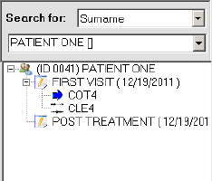
Once selected a patient from the list, it will be loaded in the underlying
area, and all his sessions and trials will be available for the elaboration
organized in tree structure.
Click the “+” symbol to expand the patient node and access the list of the
sessions for that patient. Expanding the session node obtains the list of
the trials for that session.
If a patient or a session doesn’t have the “+” symbol it doesn’t contain any

51
BTS
Biomedical
BTS TMJOINT
guide to the use of BTS DCA
data.
To compact the list and hide the trials or the sessions click the “-” symbol.
When the node is selected, the node icon is substituted by an azure arrow.
In this way the patient, the session, or the selected trial, can always be
identied..
Besides the name of the patient there is an ID number that is a code
assigned automatically by the software to the patient and cannot be
changed. It identify all the data related to this patient saved in the PC.
If the le is not physically present in the current data folder, the icon
alongside the node is cancelled with a cross
The information continues to be present in the database, but it is
not possible to use them.
When a node is selected to which data is no longer associated, the arrow
appears within a prohibited symbol.
The icon of a full recycle bin at the bottom on the right indicates that
there are data (patients, sessions or trials) which have been deleted but can
be recovered.
To recover them double click the full recycle bin symbol to access the
deleted les.
The empty recycle bin symbol indicates that there are no les which can
be recovered.
52
BTS
Biomedical
BTS TMJOINT
guide to the use of BTS DCA
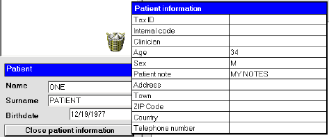
Patient, session and trial information
In the bottom left hand corner area of the main screen there are the
information of the selected patient, session and trial.
ere are two main panels:
- the rst one contains the information related to the patient that are:
• “Name”
• “Surname”
• “Birthdate”
Click the “More patient information” button to open a table which
records all the information related to that patient: :
To close the table click the “Close patient information” button.
- The second one contains information related to the trial and in particular:
• “Acquisition date”;
• “Trial notes (max 255)”.
This last eld can be updated by editing the notes eld and clicking the
“Save” icon.
53
BTS
Biomedical
BTS TMJOINT
guide to the use of BTS DCA
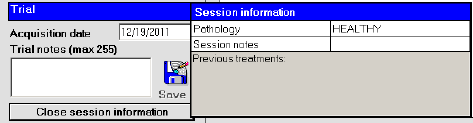
It is also possible to visualize the information of the session that contains
the selected trial by clicking on “Session information”.
“Close session information” close the panel.
Trial viewing and report generation area
e trial viewing and report generation area is made of the following
panels:
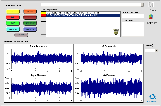
- “Patient reports”: consists of a drop box menu containing all the saved
report of the selected patient.
After selecting a report from the drop box menu the “Open” button
became active.
By clicking the “Open” button the application for the PDF reading will
be loaded and the selected report will be visualized.
- “Trial to process”: this panel contains all the trials among whom selected
the trials for the report generation.
To insert a trial in the “Trial to process” panel is enough a double-click
on the trial from the tree of the selected patient and it will be added
immediately to the trial list.
54
BTS
Biomedical
BTS TMJOINT
guide to the use of BTS DCA
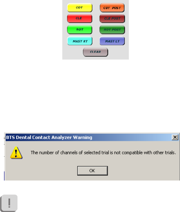
To proceed with the report generation, it is necessary to identify the type
of trial by using the 8 button at the left of the panel:
e software will automatically assign a typology among “COT”, “CLE”,
“ROT”, “MASTDX”, “MASTSX”, to each trial loaded. e “POST”
label will be assigned to the second trial of the same type loaded, while
all other trials of this typology loaded after won’t be labeled.
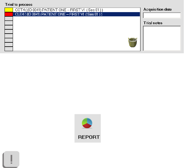
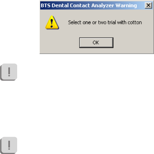
If the type that you are trying to assign to a trial is not compatible with
it a warning massage will be displayed.
For example:
Before to proceed with the report generation verify that the type
assigned to each trial is correct, otherwise modify it by selecting
the trial from the list and clicking on the right button.
55
BTS
Biomedical
BTS TMJOINT
guide to the use of BTS DCA
To facilitate the procedure of classication, when one trial is selected the
“Acquisition date” and any “Trial notes” are displayed on the right side
of the panel:
To remove a label from a trial in the list, select it and click on “CLEAR”.
To remove all the trial from the panel “Trial to process” is enough to click
on the recycled bin icon.
Once the trial labeling procedure has been properly executed it is possible
to create the report by clicking the “REPORT” button:
e report could be created only if:
• at least one “COT” type trial and one “CLE” trial have been
loaded;
• a “MASTDX” and/or “MASTSX” type trial have been
loaded.
If at least one of these two condition is not veried a warning
56
BTS
Biomedical
BTS TMJOINT
guide to the use of BTS DCA
massage will be displayed. For example:
When a PRE-POSt report must be created it is possible to use
two dierent trials of cotton type labeled as “COT” and “COT
POST”(typically when we need to compare trials acquired in
dierent days), or to use just on “COT” type trial that will be
used to normalize both the “CLE” trial and the “CLE POST”
trial (typically when we need to compare trials acquired the
same day, without modify the position of the electrodes, such as
clench test executed with and without bite).
Only the trials witch have been marked with a color correspondent
to one of the 8 trial typologies, among all the trial present in the
list “Trial to processed” will be used to construct the report.
If all the operation have been executed correctly the window for the
report management will be displayed. From that window it is possible to
select all the element to be inserted in the report. ere will be also the
button to open the print preview, to launch the print or to save the report
in the database to recall it in a second time.
e windows is divided in two area:
57
BTS
Biomedical
BTS TMJOINT
guide to the use of BTS DCA
• the main area shows, organized in TABS, the graphs, the tables and
the info that can be inserted in the report.
• the button bar contains the “Print preview”, “Print” and “Save Report”
buttons, the eld “report PDF name” in witch is visualized the report
name automatically assigned by the software (this name can be
modied by the user before to click on “Save Report”), nally there
is the “Exit” button to come back to the main screen of the software.
- “Preview of selected trial”: in this panel in shown a preview of the Trial
selected in the panel “Trial to process”.
58
BTS
Biomedical
BTS TMJOINT
guide to the use of BTS DCA
e scale of the y-axis can be modied selecting the maximum value to
be visualized among the value of the drop box menu “(+-mV)” placed at
the right of the panel.
59
BTS
Biomedical
BTS TMJOINT
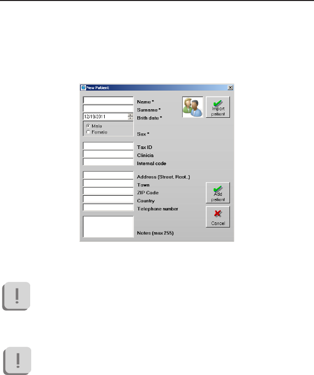
New patient
Select “New Patient” from the menu and tool bar to open the window
below:
To insert a new patient simply ll in the elds and click “Add Patient”.
The elds marked with an * are mandatory.
Click on “Cancel” to come back to the previous screen.
Any inserted data will be lost.
main features of the BTS DCA software
60
BTS
Biomedical
BTS TMJOINT
main features of the BTS DCA software
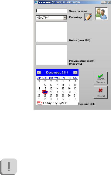
New session
Select “New Session” from the menu and tool bar to open the window
below:
To create a new session simply ll in the elds and click “Create Session”.
In particular it is required to:
• give a name to the session to be created.
This eld is mandatory.
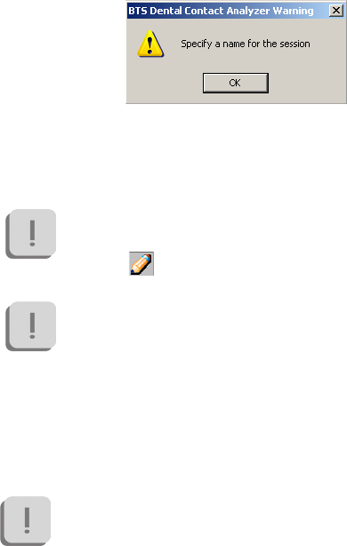
To proceed with the creation of the session the session
name must been inserted otherwise the following
warning message will be displayed:
61
BTS
Biomedical
BTS TMJOINT
main features of the BTS DCA software
• select the pathology among the voices available in the drop box
menu (automatically the rst voice of the list respect the alphabetic
order will be proposed).
the list of pathologies is completed entirely by the user.
To add, eliminate or modify a pathology from the list
click the icon, to access the “Edit pathology” window.
At the rst use of the software the pathology list will be
empty.
It is necessary to insert at least one pathology to proceed
with the session creation.
• insert any Note about the session (eld not mandatory).
• indicate any previous treatment of the patient.
For both these elds there are 255 characters available.
• modify the session date (if dierent from the date of the actual
day proposed as default).
To delete the session creation and come back to the previous screen click
on the button “Cancel”.
62
BTS
Biomedical
BTS TMJOINT
main features of the BTS DCA software
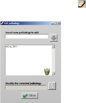
Edit Pathology
From the “New Session” window, click the symbol to open the
pathology list.
In the central panel all the pathology already inserted in the database are
listed in alphabetic order.
To add a new pathology write the name of the pathology in the eld
“Insert new pathology to add” and click the blue arrow to add the
pathology to the list.
To change a pathology:
• Select the pathology from the list. The name is shown in the eld
“Modify the selected pathology”.
• Modify the name of the pathology
• Click the icon alongside to apply the change to the list.
To delete a pathology:
63
BTS
Biomedical
BTS TMJOINT
main features of the BTS DCA software
• Select the pathology to be deleted
• Click on the recycle bin icon
• Conrm the deletion of the trial by clicking “Yes”.
To exit from the window “Edit pathology” click on “Close”.
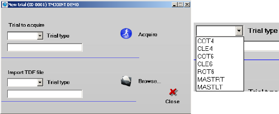
New Trial
Select “New Trial” from the menu and tool bar to open the following
window:
To create a new trial it is possible to make an acquisition or to import a
trial acquired in the past.
In any case it is necessary to select a “Type” among the voices proposed in
the drop box menu for the trial to be created.
Fill the elds relative to “Trial to acquire” if you want to proceed with an
acquisition, or ll the elds relative to “Import TDF le” if instead you
want to import a trial acquired in the past.
64
BTS
Biomedical
BTS TMJOINT
main features of the BTS DCA software
7 typologies of test are allowed:
• COT4: requires the use of 4 probes placed on the temporal
and masseter muscles. To the subject it is required to perform a
clenching of 5 seconds with two cotton roll interplaced between
the two arches, one for each side.
• CLE4: requires the use of 4 probes placed on the temporal and
masseter muscles. To the subject it is required to perform a
clenching of 5 seconds.
• COT6: requires the use of 6 probes placed on the temporal,
masseter and sternocleidomastoid muscles. To the subject it is
required to perform a clenching of 5 seconds with two cotton roll
interplaced between the two arches, one for each side.
• CLE6: requires the use of 6 probes placed on the temporal,
masseter and sternocleidomastoid muscles. To the subject it is
required to perform a clenching of 5 seconds.
• ROT6: requires the use of 6 probes placed on the temporal,
masseter and sternocleidomastoid muscles. To the subject it is
required to perform a series of head rotations.
• MASTRT: requires the use of 4 probes placed on the temporal
and masseter muscles. To the subject it is required to chew for
15 seconds on the right side.
• MASTLT: requires the use of 4 probes placed on the temporal
and masseter muscles. To the subject it is required to chew for
15 seconds on the left side.
Once all the elds have been lled in, click respectively on “Acquire” to
start the process of acquisition (see next chapter), or on “Browse...” to
select the trial to be imported directly from Windows Explorer on your
PC.
65
BTS
Biomedical
BTS TMJOINT
main features of the BTS DCA software
Before clicking on “Acquire”, ensure that the receiving unit is
connected to the PC via USB and check the status of the probes
from the probes status bar of the probes.
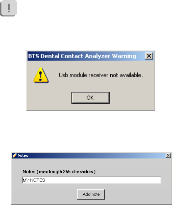
If an acquisition is launched when the receiver is not connected to
the PC, the following warning message will be displayed:
When a trial is imported the user can enter some notes that will be saved
in the database.
After selecting the test to be imported the following window will appear:
Edit the notes and click “Add note” or, if you don’t want to enter any notes
66
BTS
Biomedical
BTS TMJOINT
main features of the BTS DCA software
simply close the window.
e procedure for trial acquisition or import can be repeated several times
to add more trials to the same session.
Note that the system doesn’t allows for two tests with the same
name under the same session.
Once all the required trial were acquired or imported, click “Close” to
return to the main screen.
Data acquisition
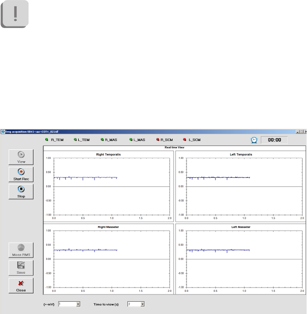
By clicking on “Acquire” from “New Trial” the following screen will be
displayed:

67
BTS
Biomedical
BTS TMJOINT
main features of the BTS DCA software
On the top bar is shown the six probes status:
Information displayed are referred in sequence to probes number 1, 2, 3,
4, 5, and 6 starting from left going to right.
For each probe there are a status LED and an identication label.
e status LED beside each channel can be:
- GREEN: if the probe is active;
- RED: if the probe is not active;
- GREY: if the probe is not allowed for the system.
e identication label is linked to the muscle is acquired with that specic
probe:
- R_TEM for the right temporal muscle,
- L_TEM for the left temporal muscle,
- R_MAS for the right masseter muscle,
- L_MAS for the left masseter muscle,
- R_SCMCL for the right sternocleidomastoid long head muscle,
- L_SCMCL for the left sternocleidomastoid long head muscle.
In case of inactive probes, the label is usually Ch1, Ch2, Ch3, Ch4, Ch5,
Ch6.
On the central area of the screen the real-time oscilloscope will show the
signals coming from the probes. ere will be displayed 4 or 6 channels
depending on the protocol chosen:
68
BTS
Biomedical
BTS TMJOINT
main features of the BTS DCA software
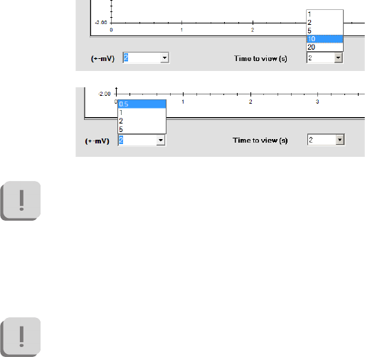
e oscilloscope allows to verify the correct probes positioning before
starting the real acquisition and to verify the proper movement execution
required to the patient.
For a better signals visualization it is possible to modify the axis scales
clicking on the drop down menu on the bottom:
To start the acquisition all probes required in the selected trial’s
protocol have to be active. Before proceeding with the next steps
verify that all the LED corresponding to the probes required by
the Protocol are green.
When everything is ready, click on “Record” to start recording the trial.
In clenching trials, with or without cotton rolls, and in chewing
tests it is better to start the acquisition just after the patient has
already start to perform the movement required from the protocol.
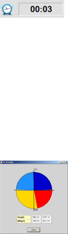
When the acquisition starts, the “Timer” on the right top of the screen
starts.
69
BTS
Biomedical
BTS TMJOINT
main features of the BTS DCA software
e clenching trials CLE4, COT4, CLE6 and COT6 stop automatically
after 5 seconds, while chewing trials MASTRT and MASTLT stop after
15 seconds.
By the way it is possible to interrupt before the record clicking on “Stop”.
e acquisition of the rotation trial ROT6 has to be interrupted manually
clicking on “Stop” when the subject executed all the movements required.
At the end of the trial data will be automatically downloaded, when this
will be complete a signals acquired preview will be shown.
It is possible to modify the visualization range to zoom in the signal to
evaluate that the trial has been performed properly before save it.
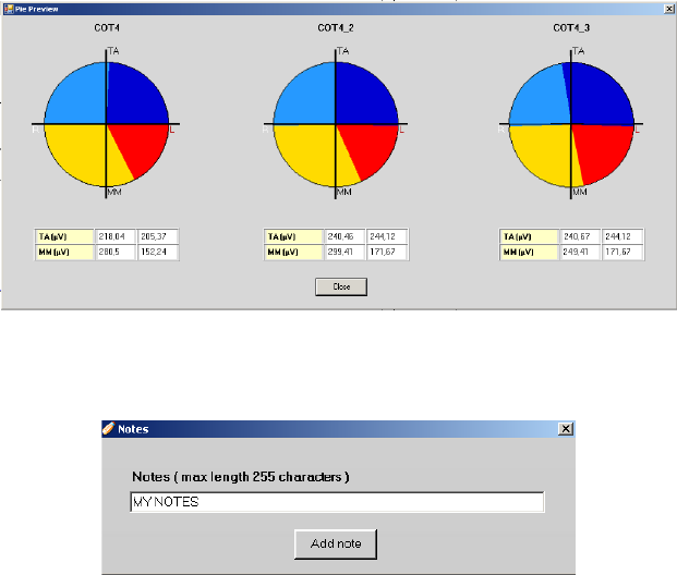
For clenching trials, (COT and CLE) at the end of each acquisition, it is
possible to visualize a preview of the pie chart related to the RMS mean
value clicking on the correct button:
70
BTS
Biomedical
BTS TMJOINT
main features of the BTS DCA software
If more than one acquisition of clenching trials has been performed,
besides the pie chart of the current trial, there will be also displaied pie
charts of the previous ones (up to two) to allow the verication of the data
repeatability:
If the acquisition is good it is possible to save the trial clicking on “Save”.
A window will appear to add, if necessary, notes related to the trial:
After edited the notes, click on “Add note” while if notes are not required
just close the window.
Once this operation is done the “New Trial” window will appear again.
71
BTS
Biomedical
BTS TMJOINT
main features of the BTS DCA software
If the trial just acquired is not good enough to be saved, it is possible to
proceed with a new acquisition. To do that click on “View” to restart the
real-time oscilloscope and repeat the recording procedure.
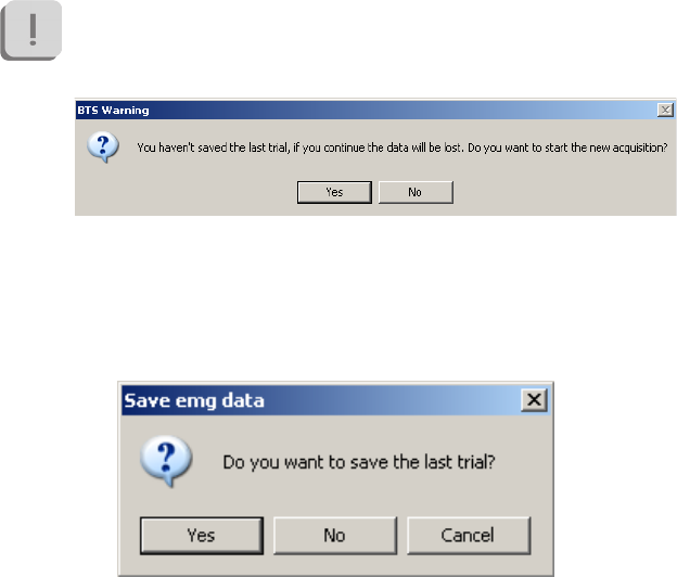
Data just acquired are not going to be recovered, for that reason
a window will ask a conrmation about choosing not to save the
last acquisition:
Finally, to exit from the acquisition and go back to the “New Trial” section,
click on “Exit”.
If the last trial has not been saved, the following screen will appear:
Clicking on “Yes” data will be stored, clicking on “No” the acquisition
window will be closed and last trial data will be canceled, nally clicking
on “Cancel” you go back to the acquisition screen.
72
BTS
Biomedical
BTS TMJOINT
main features of the BTS DCA software
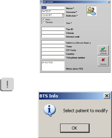
Edit patient
Select “Edit patient” from the menu and tool bar to open the following
window:
Note that to do this a patient must be selected in the database,
otherwise the following warning message will appear:
e “Edit patient” window will show all the selected patient data previously
entered. It is possible to modify them or add new ones.
When all changes have been made click on “Update patient” to save the
new data in the database.
73
BTS
Biomedical
BTS TMJOINT
main features of the BTS DCA software
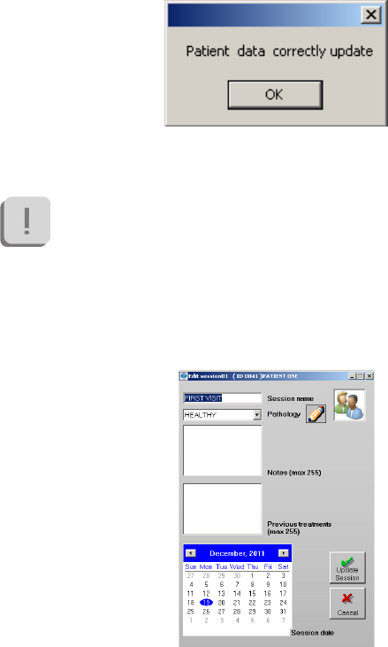
Se l’operazione è andata a buon ne comparirà la seguente nestra:
Finally, to exit without making any changes to the data click on “Cancel”.
Any change made will be lost.
Edit session
Select “Edit Session” from the menu and tool bar to open the following
window:
74
BTS
Biomedical
BTS TMJOINT
main features of the BTS DCA software
Note that to do this a patient must be selected in the database,
otherwise the following warning message will appear:
e “Edit Session” window will show all the selected patient data previously
entered.
It is possible to modify them or add new ones.
When all changes have been made click on “Update Session” to save the
new data in the database.
To exit without making any changes to the data click on “Cancel”.
Any change made will be lost.
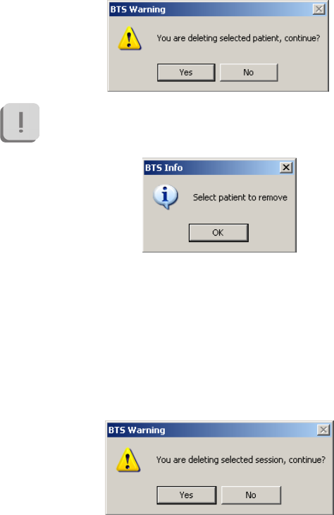
Delete patient
To remove a patient from the database, select it and choose “Delete
Patient” from the menu bar.
is operation will move the selected patient in the recycled bin together
with all sessions and trials related to him.
75
BTS
Biomedical
BTS TMJOINT
main features of the BTS DCA software
A conform to the cancellation will be asked:
Note that to do this operation a patient must be selected in the
database, otherwise the following warning message will appear:
Delete session
To remove a session from the database, select it and choose “Delete Session”
from the menu bar.
is operation will move the selected session in the recycled bin together
with all the trials related to him.
A conform to the cancellation will be asked:
76
BTS
Biomedical
BTS TMJOINT
main features of the BTS DCA software
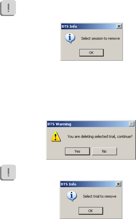
Note that to do this operation a session must be selected in the
database, otherwise the following warning message will appear:
Delete trial
To remove a trial from the database, select it and choose “Delete Trial”
from the menu bar.
is operation will move the selected trial in the recycled bin.
A conform to the cancellation will be asked:
Note that to do this operation a trial must be selected in the
database, otherwise the following warning message will appear:
77
BTS
Biomedical
BTS TMJOINT
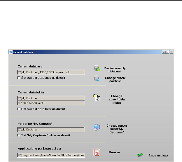
Database and data folder
From the menu bar select the “Database” option, and then the “Database
& Data folder” function to open the window below:
e eld “Current database” shows the path of the database actually
selected. It is possible to lad an other database or to create a new empty
one.
To create an empty database, click the icon “Create an empty database”:
a new window in witch enter the name of the new database will appear.
Click “Save” to create a new database. The “Current Database” eld will
more features of the BTS DCA software

78
BTS
Biomedical
BTS TMJOINT
more features of the BTS DCA software
be updated accordingly.
To work with a different database to the default one:
• Click the icon “Change current database”
• Browse the folders and select the database desired.
• Click “open” to change the database. The “Database” eld will
be updated.
If you wish to use the new database as a reference, tick the option “Set
current database as default”.
If this is not done, the setting will be lost when the BTS Dental
Contact Analyzer is closed, and the default database will be loaded
at the next launch of the program.
To change the data folder:
• Click the “Change current data folder” icon.
• Select or create the new folder.
A sub-folder will be created automatically in which the les will be saved.
The name of the subfolder is shown in brackets under “Current data
folder”.
In the gure the subfolder is “DataPOCAnalyzer”.
This folder is changed automatically when the current database is changed.
Also in this case to set the new folder as the default data folder put a check
in the “Set current data folder as default”.

79
BTS
Biomedical
BTS TMJOINT
more features of the BTS DCA software
If this is not done, the setting will be lost when the BTS Dental
Contact Analyzer is closed, and the data will be saved in the
default folder at the next launch of the program.
The reference My Captures folder is that which contains all the le
required by the software to work properly.
It is therefore recommended to choose a new folder only with the
consent of the technical staff of BTS.
To change this folder:
• Click the icon “Change current folder “My Captures””.
• Select the new reference folder (which will contain all the le
required by the software to work properly)
Also in this case to set the new folder as the default data folder put a check
in the “Set “My Captures” folder as default”.
If this is not done, the setting will be lost when the BTS Dental
Contact Analyzer is closed, and the old “My Captures” folder will
be used at the next launch of the program.
From this screen you can then select the application used to read the
report in PDF format.
To select the application click on “Browse...” and select the exe le you
want to use.
Please note that if no application is selected you can not see the
reports.
80
BTS
Biomedical
BTS TMJOINT
more features of the BTS DCA software
To apply the changes click “Save and exit”.
Managing les in the recycle bin
If you wish to remove a patient, session or trial, the le is moved to the
recycle bin.
To access the les held in the recycle bin, double click the icon representing
the recycled bin which appears in the patient list.
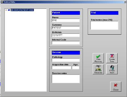
e following windows will appear:
In the left side of the panel there are all the data contained in the recycled
bin organized per patient with a tree structure.
By expanding the nodes it is possible to access to sessions and trials.
81
BTS
Biomedical
BTS TMJOINT
more features of the BTS DCA software
In the le tree the node labels may have three different colors:
• The black label indicates that the le (patient, session or trial)
has been removed from the database together with all the les
associated with it.
• The dark grey label and icon indicate that the le is present
in the database, but some elements associated with it have been
removed (e.g. a session of a patient has been removed, or a trial
from a session).
• The light grey label indicates that the le has been deleted along
with the root le (e.g. a patient main le has been deleted. As a
result all of the related sessions and trials have also been removed).
Selecting a node which has been removed updates the patient, session and
trial information.
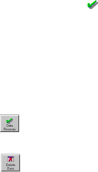
From the “Deleted data” window it is possible to carry out four different
operations:
This button recovers the selected le.
When a session is selected all the associated trials will also be
recovered. When a patient is selected all the associated sessions
and trials will also be recovered.
This button eliminates the selected le permanently.
Before eliminating the le, a conrmation will be requested.
If you eliminate a le, it cannot be recovered. Eliminating a
session also eliminates all the associated trials. Eliminating a
patient also eliminates the associated sessions and trials.
82
BTS
Biomedical
BTS TMJOINT
more features of the BTS DCA software
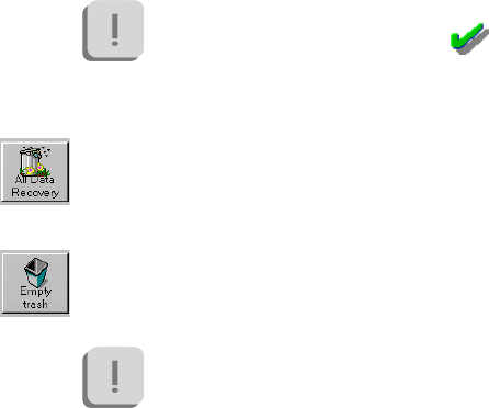
If the button is deactivated, it means that the le is not
present in the recycle bin (the icon alongside dark
grey text), or it may not be recovered individually. In this
case it is necessary to select the root le.
This button recovers all the les in the recycle bin. All patients,
sessions and trials will be available again in the database and the
recycle bin will be empty.
This button permanently eliminates all the les in the recycle bin.
A conrmation must be given for this operation.
Conrming the elimination means that the les will no
longer be recoverable. At the end of this operation the
recycle bin will be empty.
83
BTS
Biomedical
BTS TMJOINT
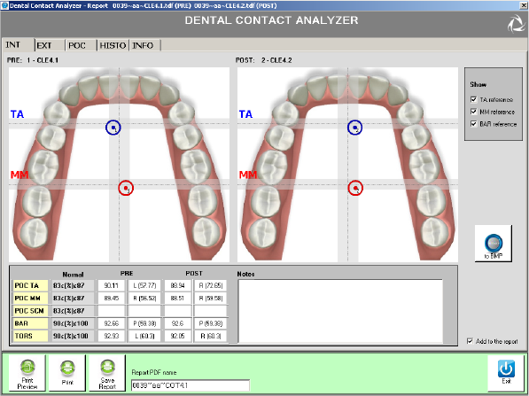
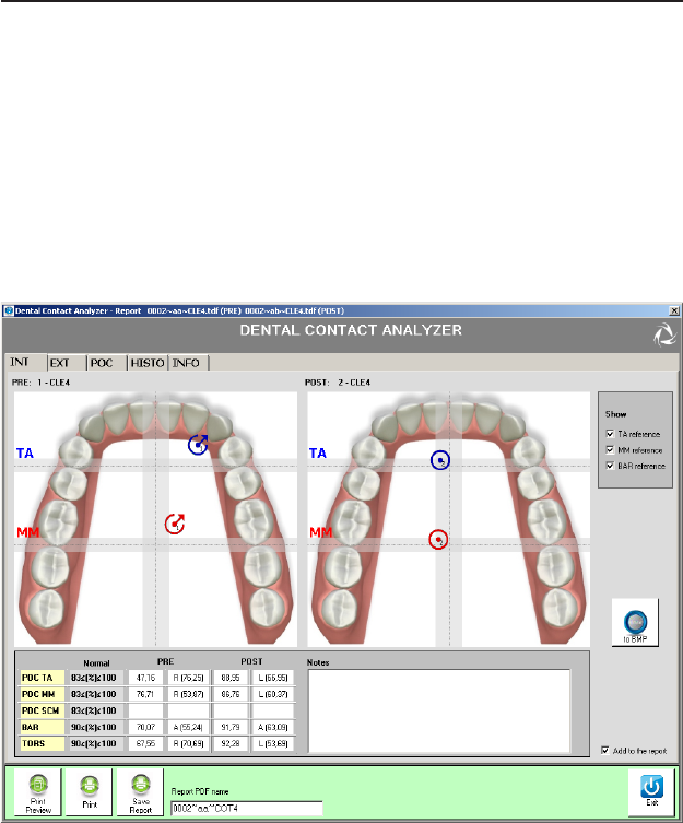
e data report is automatically generated by the software DCA. e
results of the data elaborations are organized in tabs: INT, EXT, POC,
ISTO and MAST.
Moreover there is an INFO tab for the customization of the printed report.
INT tab
guide to the report data reading
84
BTS
Biomedical
BTS TMJOINT
guide to the report data reading
e elaborated data are divided into PRE and POST sections, for the
comparison of two tests of the same acquisition session, or of tests made
in dierent temporal session. is is helpful in evaluating the treatment
ecacy and for the patient follow up.
e graphic shows a dental arch, which works as a 2D morphological map,
on which are superimposed icons “target” style (they will be so called in
the rest of the document), positioned in order to summarize the occlusal
condition, according to the calculated indices, whose values are given in
the table below.
• POC: percentage overlapping coecient
It is an index of the standardized contraction symmetry within the
same muscular couple. It expresses, in percentage terms, the dierence
in electrical signal generated by a muscle couple during a maximum
voluntary contraction (MVC) compared to its homologous standardized
value.
If the two homologous muscles of each pair are contracted in perfect
symmetry, thanks to a functionally balanced dental occlusion, the POC
result is expected close to 100%.
While if muscle couples show standardized values in percentage terms
dierent from each other, the POC turns out to be considerably less than
100%.
When the POC exceeds 83%, there is a normal muscular symmetry,
induced by the contact of the teeth, otherwise, the dental contact is
inuencing the neuromuscular equilibrium of the patient.
With the 4-channel protocol, are calculated the POC of the anterior
temporal and masseter muscles, which are respectively indicated by POC
TA and POC MM, indicators of the inuence of tooth contact on the

85
BTS
Biomedical
BTS TMJOINT
guide to the report data reading
neuromuscular balance of the stomatognathic system; with 6-channel
protocol, is calculated in addition the coecient of overlapping
percentage of the sternocleidomastoid muscles POC SCM, indicator
of the inuence of tooth contact on the cranio-cervical neuromuscular
balance.
For each POC is also indicated which is the predominant muscle and
in what percentage it contributes to the total level of asymmetry. In
particular, the letter “R” indicates that there is a prevalence of the right
muscle while the letters “L” that there is prevalence of the left one.
• POC: graphical representation
e central vertical line, dark gray, dotted, corresponds to the 100%
value and the light-gray vertical band indicates the range of normality, up
to the value 83%, both right and left of central line, in order to represent
the prevalence of right or left muscle activity.
e blue target refers to the POC index of the anterior temporal (POC
TA), while the red refers to the POC index of the masseters (POC MM).
e POC TA index corresponds to the inuence of dental
contacts of the incisors, canines and rst premolars.
e index POC MM corresponds to the inuence of dental
contacts of the premolar and molar teeth.
Values of POC out of the norms indicates a quality of contact
prevalent or lack of one side respect the controlateral.
e target is represented at a distance from the central vertical line
corresponding to the calculated value.
If the POC value is more than 83%, the target is represented within the
gray central band, while if it is lower it is represented outside the normal
86
BTS
Biomedical
BTS TMJOINT
guide to the report data reading
range.
So it is easy to observe the predominance of the right or left temporal in
the anterior quadrants, and the masseter, left or right, in the posterior
quadrants.
e value of the POC SCM does not aect the targets position, but only
the percentage of co-contraction of neck muscles during MVC.
• BAR: Barycenter
It provides an estimate of the occlusal barycenter position. It is obtained
by calculating the percentage overlapping coecient between the
activities of the couple of temporal and the activities of the couple of
masseter (while the POC index compares single homologous muscle).
When the contact points tend to focus on the molars, the masseters
record a major contraction respect to the correspondent temporalis
(Posterior barycenter).
Instead, in the occlusal condition in which the barycenter moves in the
anterior-lateral areas, that means until the rst-second premolar, the
temporalis express major contraction forces (Anterior barycenter). In
this case there is a bilateral overload of the joints that, with the passing of
time, can lead to pathological conditions.
For the BAR index if the position of the barycenter is mainly anterior,
there will be the letter “A”, will also be indicated in what percentage the
anterior temporal muscles contribute to move the barycenter upwards.
Vice versa there will be the letter “P” and will also be indicated in what
percentage the masseter muscles contribute to move backwards the
barycenter.
• BAR: graphical representation
e normal value of the BAR index is > 90%.

87
BTS
Biomedical
BTS TMJOINT
guide to the report data reading
e two horizontal dark gray lines with dots, superimposed to dental
arch, represent the BAR value equal to 100%, while the gray bands
represent the normal range up to 90%.
e two targets will be translated at a distance from the relative horizontal
line of a value corresponding to the BAR index calculated, upwards
or downwards following the prevalence of the BAR index (anterior or
posterior), according to the occlusal condition.
e value and the direction of the vertical displacement of the two target
points are then exactly the same.
e BAR value in the normal population always expresses a
prevalence of dierential activities of the couple of masseter
muscles compared to that of temporal.
is condition is reversed in the second skeletal class in which
the temporal muscles always express a dierential electrical
activity greater than the masseter’s one.
• TORS: torsion
It provides an estimate of the rotation attitude of the mandible in the
horizontal plane when it is in occlusion with the superior maxilla. Is
obtained from the comparison of the torque moment of the right
temporal and the left masseter couple (by convention rightward torque)
with the torque moment of the left temporal with the right masseter
couple (by convention leftward torque).
When this index is >90%, torque moments do not occur on the mandible.
On the contrary, if this index is outside of the normal ranges that means
below 90%, the muscles tend to twist the lower jaw to the right or left
depending on whether one or the other muscular couple prevalence, due
to the presence of occlusal fulcrums.

88
BTS
Biomedical
BTS TMJOINT
guide to the report data reading
ere will be the letter “R” when there is mainly a torsion to the right,
while the letters “L” when the torsion is mainly to the left. It will be
also reported in what percentage the dominant couple contributes to the
creation of torque.
• TORS: graphical representation
e resulting action of the temporalis muscle, added to the resulting
strength of the contralateral masseter, generates a pair of forces with a
moment which tends to laterodeviate the jaw in the direction of the
resultant of the anterior temporal.
If the right is greater, the target will be not only circular, but it will report
an arrow to the right.
Similarly, the arrow will be leftward if the coecient calculated for the
couple anterior temporal-right masseter is greater.
We must not think that there is a real torsion of the mandible
because we are under static conditions. Any clinical condition,
which can be likened to pre-contact and then to tooth contact
sliding, is therefore already occurred. e TORS index expresses
a condition clinically worse because detectable only using
instruments, that is the presence of fulcrums.
e muscles continue to activate and inhibited themselves in
the pursuit of stability. Clinically this corresponds to a contact
mainly in the antero lateral area of the dental arch or to a
contact qualitatively insucient in the latero posterior sectors.
It is generally associated also with temporomandibular joint
problems. If associated with values of IMPACT lower than
normal, it may indicate the presence of both, pain and protective
mechanism to nociceptive stimulus.
89
BTS
Biomedical
BTS TMJOINT
guide to the report data reading
• NOTE
In the “Notes” eld it is possible to add a text description that the
clinicians want to include in the printable report as a comment of the
represented data in the INT tab.
• “Add to report” checkbox
If the check is in the box, the INT tab content will be included in the
printed report, otherwise it will be ignored.
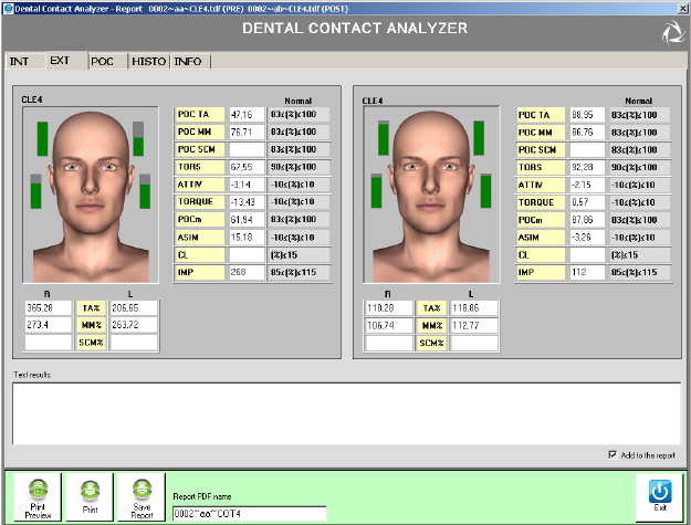
“EXT” tab
90
BTS
Biomedical
BTS TMJOINT
guide to the report data reading
In this tab are represented the ulterior calculated indices, reporting for an
easier reading also the values of the coecients already seen in the previous
tab.
e referring indices are TA%, MM%, SCM%, ATTIV, TORQUE,
POCm, ASIM, CL and IMP.
• TA%, MM%, SCM%
ese indexes represent in percentage the standardized average value of
the activity respectively of the anterior temporal muscles, masseters and
sternocleidomastoids left and right.
e graphical representation includes a 3D model, for a male or female,
according to the patient for whom the report relates.
e status bars represent the level of electrical intensity, measured in the
muscle near which are represented.
Depending on the protocol used (4 or 6 channels), 4 or 6 bars are
displayed corresponding to the anterior temporal muscles, masseters and
sternocleidomastoids.
e muscle that expresses the greater amplitude value of the electric
potential, percentualized, is represented with a full bar and becomes the
reference scale for the bars graphical representation of the other muscles,
which will be compared to.
In the example shown in the gure the right TA% is 83.57% and is
the highest value of the 4. en the bar will be represented “full” and
the others will be represented in proportion according to the calculated
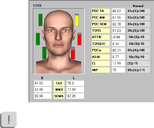
91
BTS
Biomedical
BTS TMJOINT
guide to the report data reading
values: left TA% = 57.92%, right MM = 45.62%, left MM = 38.67%.
e bars can be green if the width value is greater than 83%, yellow if
the amplitude is less than 83%, but above 75%, red if the width value is
less than 75%.
Similar interpretation for the SCM muscle, shown in the gure below as
an example.
e SCM POC is calculated only when using the POC6 protocol.
• ATTIV: activation
It’s a parameter similar to the BAR, but computed on the average value of
maximum contraction and compared to zero, instead of 100%.

92
BTS
Biomedical
BTS TMJOINT
guide to the report data reading
Provides an estimate of the occlusal barycenter position.
It is very useful for an immediate interpretation of the biomechanics
levers induced by the contact of the teeth.
When the contact points tend to focus on the molars, the masseters
record a greater contraction than the corresponding temporalis and so
the index takes a positive value.
In the occlusal condition in which the barycenter moves in the anterior-
lateral areas, that means until the rst-second premolar, the temporalis
express greater contraction forces and the index becomes negative.
Normally this index is always positive except in the second
skeletal class in which the index is usually negative.
For the resolution of TMJ (temporomandibular joint) acute pain
problems it must be nd a condition biomechanically favorable
to the discharge of the forces burden on the TMJ that leads to a
positivization of this index.
• TORQUE: mandibular torque
It’s a parameter similar to the TORS, but compared to zero, instead of
100%.
e resultant force of the action of the temporalis muscle, added to the
resultant force of the controlateral masseter, generates a force couple. e
moment of this couple tends to laterodeviate the jaw in the direction
of the resultant of the anterior temporal: if the right is greater, the
torque values will be negative; while it will be positive it the left TA is
predominant.
• POCm : medium percentage overlapping coecient
It is simply the medium between the TA POC and the MM POC. It

93
BTS
Biomedical
BTS TMJOINT
guide to the report data reading
represents the global POC. Also in this case the normality range is on
≥83% values.
• ASIM: asymmetry
is index allows you to compare the activity of the muscles of the right
side with the muscles of the left side.
A positive value indicates a greater activation of the right side, while a
negative value indicates a greater activation of the left side. e normal
range is between -10 and 10.
• CL: Cervical Load
is index is calculated only when using the protocol POC6,
which includes the performance of a test of maximum rotation
of the head to the right and left, in addition to the trials of
clenching with and without cotton roll (thus with maximum
intercuspation).
Gives the percentage of co-contraction of SCM muscle during clenching:
a cervical load of 0% indicates an absence of recruitment, while a value of
100% indicates that the recruitment is maximum.
e normal values occurs at CL ≤ 15%.
Excessive values of CL indicate an excessive recruitment of neck
muscles during the MVC, which may favor the persistence of
clinical conditions for neck ache, especially in clencher patients.
• IMP: Impact
this index indicates the muscle work, represented geometrically by the

94
BTS
Biomedical
BTS TMJOINT
guide to the report data reading
area under the curve of the electrical activity of muscles examined in the
time.
e normal range of the index are in the range 100% ± 15%.
Higher values indicated that the subject should be considered a
strong clencher.
Values lower than normal may express a condition of
proprioceptive inhibition acute with presence of pain during
MVC, or chronic with presence of a nociceptive protective
reex.
If the POC, TORS and BAR indexes are normal the IMP index
is related to the vertical dimension.
In this case there are indications on the possibility of raising
(index higher than normal) or reducing (index lower than
normal) the vertical dimension, compatibly with the aesthetic
condition of the patient.
• Outcome
It is possible to add some notes to the report. Write them in this box to
put them in the printed report.
• “Add to report” Checkbox
If the check is in the box, the contents of the EXTtab will be included in
the printed report, otherwise it will be ignored.
POC tab
In this tab the average activity of the four muscles Masseter right and left
and Temporal right and left, are represented by pie charts.
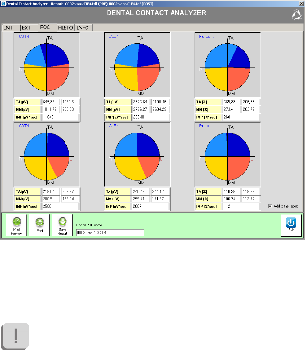
95
BTS
Biomedical
BTS TMJOINT
guide to the report data reading
e rst and second columns show the average activity of 4 muscles in
microvolts, relative to clenching trials performed respectively with and
without cottons. e third column, instead, shows the percentage value
of the average activity of the 4 muscles as the ratio between the values
obtained from the clenching trial without cotton and those with cotton.
In order to evaluate the occlusal state you must refer to this third
column.
e dark blue sector represents the left temporal muscle activity while the
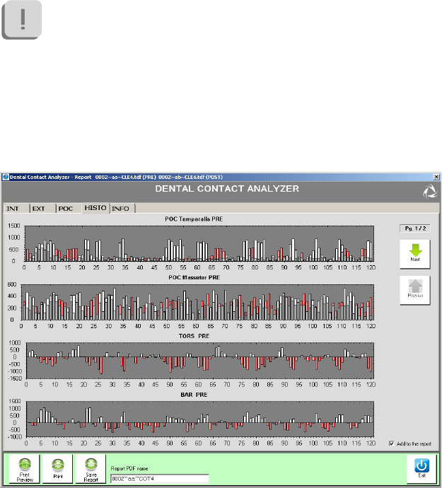
96
BTS
Biomedical
BTS TMJOINT
guide to the report data reading
light blue sector the one of the right, the red sector represents the activity
of the left masseter muscle, while the yellow of the one of right.
With a good neuromuscular balance, corresponding to the
absence of malocclusion, the colors will be equally distributed in
the 4 quadrants.
If you are analyzing two sessions (PRE, POST), the graphs for the second
session can be visualized on a second row.
ISTO tab
97
BTS
Biomedical
BTS TMJOINT
guide to the report data reading
e tab “ISTO” provides an alternate view of the main indices calculated:
Masseter POC, Temporal POC, Sternocleidomastoid POC (where
provided 6 channels), TORS and BAR.
In the graphs of the POC the activities associated to homologous muscles
are represented as histograms.
e activity of the right side (identied by white color) is compared with
the activity of the left side (identied by red color): for each bar will be
colored the data of the dominant muscle activity, while the contralateral
muscle will be represented in gray.
e values for each bar are calculated considering the average value of
muscle activity of the clenching trial normalized with respect to the
clenching trial execute with cottons in an interval of 25 ms.
When the white is prevalent there is an activity of the muscle of the right
side more pronounced, while when is the red to prevail, the left side is
dominant.
Is then given information on a possible asymmetry of muscle.
Regarding the TORS index any torsion attitudes rightward are represented
with the color white, while those leftward with the color red.
Finally regarding the BAR index the white color indicates that the
barycenter is moved anteriorly, while the red color, posteriorly.
If you are analyzing two sessions (PRE, POST), the graphs for the second
session can be viewed by clicking on “Next”.
e “Previous” button allows returning to the charts of the rst session.
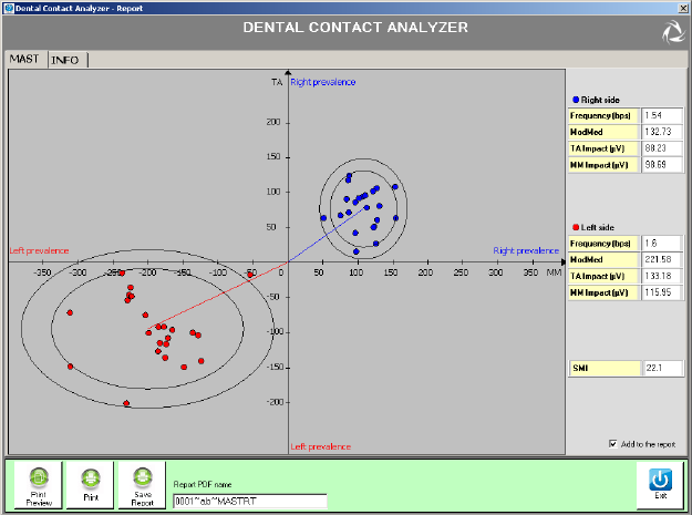
98
BTS
Biomedical
BTS TMJOINT
guide to the report data reading
MAST tab
e chewing protocol is composed of two separate trials, of 15 seconds
each, in which the patient must chew a chewing gum holding it, for the
entire duration of the test, on one side only.
Produces, as a result, a graph about the coordination of masticatory muscles
TA and MM: while, therefore, with the POC and the evaluation of the
clenching, we evaluate the neuromuscular balance (Static condition), with
the mastication protocol we evaluate the neuromuscular coordination
(Dynamic condition), by analyzing the repeatability of the muscular
patterns.
99
BTS
Biomedical
BTS TMJOINT
guide to the report data reading
e ideal situation, corresponding to a good level of chewing coordination,
is when the two ellipses of condence are equidistant from the origin and
present reduced dimensions.
In addition to the graphical representation, some numerical indexes are
calculated, for left and right side of chewing:
• Frequency (bps)
It is the number of masticatory acts per second.
• ModMed
It is the distance from the center of the graph and the center of the ellipse
of representation.
• TA Impact (uV)
It is an index of the work done by the anterior temporal muscles during
the test.
• MM Impact (uV)
It is an index of the work done by the masseter muscles during the test.
• SMI: Index of chewing symmetry.
It is a unique index, not dierentiated by side. e ideal is a value of
about 50%.
Dental contact analyzer allows processing also a single test: in this case will
be represented a single ellipse for the side “measured”. e index SMI, in
this case, will not be calculated.
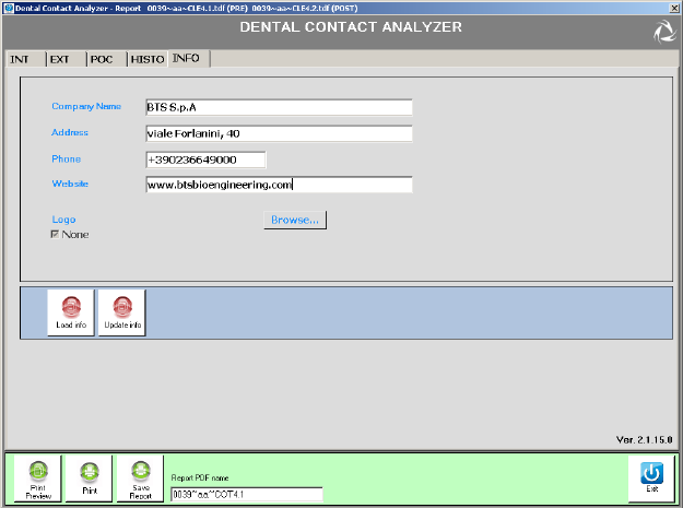
100
BTS
Biomedical
BTS TMJOINT
guide to the report data reading
INFO tab
is tab allows you to enter data to customize the report and upload your
own logo if desired.
To do this, complete the elds of interest and click on “Browse” to select
the image of your logo directly from your PC or put a check next to
“None” if you do not want to use this option.
Once you have completed entering the info you need to click on “Modify
Info” to ensure that data is stored and included in the report. At rst use,
the elds are empty.
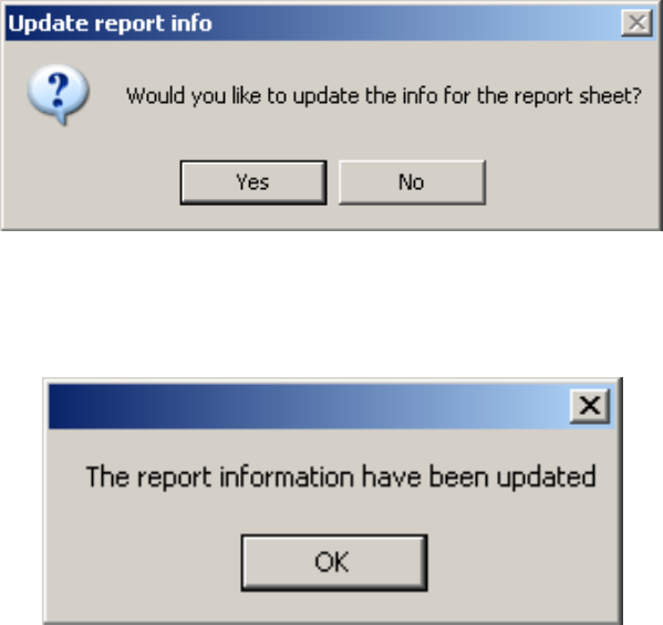
101
BTS
Biomedical
BTS TMJOINT
guide to the report data reading
Saving the data they will be automatically loaded at the next opening.
It is possible to make further changes to the saved data.
To save these changes it is necessary to click on “Modify info”. e
following windows will appear:
Clicking on “Yes” to report information will be updated and will no longer
be possible to recover previous data.
If the operation has been successful you will see the following screen:
If you do not want to save the changes click on “Upload Info” to reload
the last save.

103
BTS
Biomedical
BTS TMJOINT
Wireless Probes
Geometry: variable
Electrodes: standard with clip connection
Separation: min: 16mm - max: 66mm
Autonomy: 5h of use
some days stand-by
Battery: rechargeable, lithium ion
Dimensions: 17x36x8mm mother electrode
diameter 17 x 8mm satellite electrode
Weight: <9g battery included
Frequency used: ISM band
2.4GHz (standard IEEE802.15.4)
Input impedance: >10 GOhm
CMMR: >110 dB @ 50-60Hz
Resolution: 16bit
Acquisition frequency: up to 4KHz
Sensitivity: 1μV
Measure accuracy*: ± 2%
Receiving Unit
Connection: USB
Dimensions: 82x44x22,5mm
Weight: 80 gr
Frequency used: ISM band
appendix A
technical specications
104
BTS
Biomedical
BTS TMJOINT
appendix
2.4GHz (standard IEEE802.15.4)
* e system is calibrated at the factory. No further calibration is required

105
BTS
Biomedical
BTS TMJOINT
appendix B
environmental specications
Min Max Note
Operating Temperature -20° +45°
Operating Humidity 50% 80% Relative,
non-condensing
Storage and Transport
Temperature 0° +40°
Storage and Transport
Humidity 50% 80% Relative,
non-condensing
Altitude 0m 2000m
Degrees of protection provided by the dangerous enclosures of water and
dust (IEC 60529): IPX0.

106
BTS
Biomedical
BTS TMJOINT
appendix C
power supply and switch o
e receiving unit is powered by the USB port.
To switch o the system the following operation must be done:
- Exit from the DCA application
- Unplug the receiving unit from the USB port.
- Put the probes in Stand-By placing them on the “Charger”.

107
BTS
Biomedical
BTS TMJOINT
BTS TMJOINT probes are internally powered.
e Probe battery replacement can be done only by BTS qualied
personnel.
e probes are sealed to avoid the access to the internal circuit
components.
Batteries are equipped with battery protection circuit to:
-over-voltage, threshold 4.3V
-under-voltage, threshold 2.8V
- short-circuits
e specic characteristic of the Wireless probes equipped with the battery
are:
Quantity: 1 per each EMG probe
Technology: lithium polymer (Li-Poly)
Removable: NO, BTS technical service is required
appendix D
battery
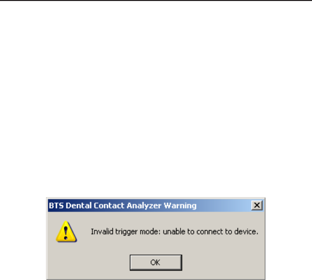
108
BTS
Biomedical
BTS TMJOINT
appendix E
troubleshooting guide
Warning – Invalid trigger mode
During the hardware installation, the USB port dedicated to the receiver,
is congured.
May happen that these port settings went lost.
is event may occur for example when another USB device is connected
to the PC and the PC assigns to it the same port previously assigned to the
receiver, returning the port setting to the default conguration.
In these cases it may occur that by launching an acquisition the following
warning message may appear:
In this case to proceed immediately with the acquisition, it is necessary
to restart the application, however the same problem will recur in later
acquisitions.
To resolve this problem you must repeat the USB port conguration
procedure described in the “Hardware Installation” paragraph of the
“Installation” chapter.
109
BTS
Biomedical
BTS TMJOINT
appendix F
declaration of conformity
DECLARATION OF CONFORMITY
BTS SpA
Via della Croce Rossa 11, 35129 Padova (PD) – Italy
Tel. +39 049 981 5500 Fax +39 049 792 9260
declare under our sole responsibility that the product(s):
name / description: Electromyographic system / device for the functional analysis of dental occlusion.
model: TMJOINT
S/N: SN
satisfies the essential requirements of the Medical Devices Directive 93/42/EC (and its amendments inluding
2007/47/CE), and therefore carries the CE marking of the European Union. The conformity assessment procedure is
according to the article 11 of the directive (Annex II.3 full quality assurance) and the article 12 it is not applicable.
In accordance with Annex IX of the 93/42/EC directive it is classified as follow:
CLASS “IIa” (rule 10)
In accordance with IEC 60601-1 is also classified as follow:
Class: internally powered device Applied part type: BF
The product conforms to the following standards:
EN ISO 14971 Medical Devices - Application of risk management to medical devices.
IEC 60601-1 Medical Electrical Equipment - Part 1: General Requirements for basic safety and
essential performance.
IEC 60601-1-2 Medical Electrical Equipment - Part 1-2: General requirements for basic safety and
essential performance - Collateral standard: electromagnetic compatibility -
Requirements and tests.
IEC 60601-1-6 Medical Electrical Equipment - Part 1-6: General Requirements for basic safety and
essential performance - collateral Standard: Usability
EN 62304 Medical device software - Software life-cycle processes
ETSI EN 301 489-3 Electromagnetic compatibility and Radio spectrum Matters (ERM) – Electromagnetic
Compatibility (EMC) – standard for radio equipment and services – Part 3: Specific
conditions for Short-Range Devices (SRD) operating on frequencies between 9 KHz and
40 GHz.
ETSI EN 301 440-2 Electromagnetic compatibility and Radio spectrum Matters (ERM) – Short Range Devices
(SRD) – Radio equipment to be used in the 1 GHz to 40 GHz frequency range – Part 2:
Harmonized EN covering essential requirements of Article 3(2) of the R&TTE Directive.
This compliance is valid ONLY for the equipment identified when used in a manner consistent
with the intent of the referenced documents and according to the product’s usage manual.
Notified Body : TÜV Product Service GmbH, Zertifizierstelle, Ridierstrasse 65, 80339 München – Germa-
ny, Identification N. 0123.
EC certificate N. G1 12 10 65301 003 valid until January, 16 2018.
Padova, Date
Bruno Ros
CEO
BTS S.p.A.

110
BTS
Biomedical
BTS TMJOINT
appendix
1. Ferrario VF, Sforza C, D’Addona A, Miani A Jr.
Reproducibility of Electromyographic measures: a statistical analysis.
J Oral Rehabil. 1991 Nov;18(6):513-21. PubMed PMID: 1845607.
2. Ferrario VF, Sforza C, Miani A Jr, D’Addona A, Barbini E.
Electromyographic activity of human masticatory muscles in normal
young people.
Statistical evaluation of reference values for clinical applications.
J Oral Rehabil. 1993
3. Ferrario VF, Sforza C.
Biomechanical model of the human mandible in unilateral clench:
distribution of temporomandibular joint reaction forces between
working and balancing sides.
J Prosthet Dent. 1994 Aug;72(2):169-76. PubMed PMID: 7932264.
4. Ferrario VF, Sforza C.
Coordinated electromyographic activity of the human masseter and
temporalis anterior muscles during mastication.
Eur J Oral Sci. 1996 Oct-Dec;104(5-6):511-7. PubMed PMID:
9021318.
5. Ferrario VF, Sforza C, Serrao G.
e inuence of crossbite on the coordinated electromyographic
activity of human masticatory muscles during mastication.
appendix G
bibliography
111
BTS
Biomedical
BTS TMJOINT
appendix
J Oral Rehabil. 1999 Jul;26(7):575-81. PubMed PMID: 10445477.
6. Ferrario VF, Sforza C, Serrao G, Colombo A, Schmitz JH.
e eects of a single intercuspal interference on electromyographic
characteristics of human masticatory muscles during maximal
voluntary teeth clenching.
Cranio. 1999 Jul;17(3):184-8. PMID: 10650405.
7. Ferrario VF, Sforza C, Colombo A, Ciusa V.
An electromyographic investigation of masticatory muscles symmetry
in normo-occlusion subjects.
J Oral Rehabil. 2000 Jan;27(1):33-40. PubMed PMID: 10632841.
8. Ferrario VF, Sforza C, Serrao G, Fragnito N, Grassi G.
e inuence of dierent jaw positions on the endurance and
electromyographic pattern of the biceps brachii muscle in young
adults with dierent occlusal characteristics.
J Oral Rehabil. 2001 Aug;28(8):732-9. PubMed PMID: 11556954.
9. Ferrario VF, Marciandi PV, Tartaglia GM, Dellavia C, Sforza C.
Neuromuscular evaluation of post-orthodontic stability: an
experimental protocol.
Int J Adult Orthodon Orthognath Surg. 2002;17(4):307-13. PMID:
12596694.
10. Ferrario VF, Serrao G, Dellavia C, Caruso E, Sforza C.
Relationship between the number of occlusal contacts and masticatory
muscle activity in healthy young adults.
Cranio. 2002 Apr;20(2):91-8. PubMed PMID: 12002835.
112
BTS
Biomedical
BTS TMJOINT
appendix
11. Ferrario VF, Sforza C, Tartaglia GM, Dellavia C.
Immediate eect of a stabilization splint on masticatory muscle
activity in temporomandibular disorder patients.
J Oral Rehabil. 2002 Sep;29(9):810-5. PubMed PMID: 12366533.
12. Ferrario VF, Sforza C, Dellavia C, Tartaglia GM.
Evidence of an inuence of asymmetrical occlusal interferences on the
activity of the sternocleidomastoid muscle.
J Oral Rehabil. 2003 Jan;30(1):34-40. PubMed PMID: 12485381.
13. Ferrario VF, Tartaglia GM, Maglione M, Simion M, Sforza C.
Neuromuscular coordination of masticatory muscles in subjects with
two types of implant-supported prostheses.
Clin Oral Implants Res. 2004 Apr;15(2):219-25. PubMed PMID:
15008934.
14. Ferrario VF, Sforza C, Zanotti G, Tartaglia GM.
Maximal bite forces in healthy young adults as predicted by surface
electromyography.
J Dent. 2004 Aug;32(6):451-7. PubMed PMID: 15240063.
15. Ferrario VF, Tartaglia GM, Galletta A, Grassi GP, Sforza C.
e inuence of occlusion on jaw and neck muscle activity: a surface
EMG study in healthy young adults.
J Oral Rehabil. 2006 May;33(5):341-8. PubMed PMID: 16629892.
16. Ferrario VF, Tartaglia GM, Luraghi FE, Sforza C.
The use of surface electromyography as a tool in dierentiating
temporomandibular disorders from neck disorders.
113
BTS
Biomedical
BTS TMJOINT
appendix
Man er. 2007 Nov;12(4):372-9. Epub 2006 Sep 14. PubMed PMID:
16973402.
17. Sforza C, Zanotti G, Mantovani E, Ferrario VF.
Fatigue in the masseter and temporalis muscles at constant load.
Cranio. 2007 Jan;25(1):30-6. PubMed PMID: 17304915.
18. Dellavia C, Romeo E, Ghisol M, Chiapasco M, Sforza C, Ferrario VF.
Electromyographic evaluation of implant-supported prostheses in
hemimandibulectomy-reconstructed patients.
Clin Oral Implants Res. 2007 Jun;18(3):388-95. Epub 2007 Feb 13.
PMID: 17298492.
19. Ries LG, Alves MC, Bérzin F.
Asymmetric activation of temporalis, masseter, and sternocleidomastoid
muscles in temporomandibular disorder patients.
Cranio. 2008 Jan;26(1):59-64. PMID: 18290526.
20. Tartaglia GM, Moreira Rodrigues da Silva MA, Bottini S, Sforza C,
Ferrario VF.
Masticatory muscle activity during maximum voluntary clench in
dierent research diagnostic criteria for temporomandibular disorders
(RDC/TMD) groups.
Man er. 2008 Oct;13(5):434-40. Epub 2007 Jul 20. PubMed PMID:
17643338.
21. Tartaglia GM, Testori T, Pallavera A, Marelli B, Sforza C.
Electromyographic analysis of masticatory and neck muscles in
subjects with natural dentition, teeth-supported and implant-
114
BTS
Biomedical
BTS TMJOINT
appendix
supported prostheses.
Clin Oral Implants Res. 2008 Oct;19(10):1081-8. PubMed PMID:
18828826.
22. Ferrario VF, Sforza C, Tartaglia GM.
Commentary to Suvinen and Kemppainen (JOR 2007;34:631-44).
J Oral Rehabil. 2009 Jan;36(1):9-10. PubMed PMID: 19207367.
23. De Felício CM, Sidequersky FV, Tartaglia GM, Sforza C.
Electromyographic standardized indices in healthy Brazilian young
adults and data reproducibility.
J Oral Rehabil. 2009 Aug;36(8):577-83. Epub 2009 Jun 22. PubMed
PMID: 19548958.
24. E. Di Palma, M. Leopardi, S. Alonzi, M. Lucci, V. Parziale C. Chimenti
Eetti immediati di uno splint di stabilizzazione sull’attività dei
muscoli masticatori in pazienti disfunzionali
Immediate eects of an occlusal splint of stabilization on the
masticatory muscles activity in disfunctional patients
Ortognatodonzia Italiana vol. 16, 2-2009.
25. Sforza C, Montagna S, Rosati R, DE Menezes M.
Immediate eect of an elastomeric oral appliance on the neuromuscular
coordination of masticatory muscles: a pilot study in healthy subjects.
J Oral Rehabil. 2010 Nov;37(11):840-7. doi: 10.1111/j.1365-
2842.2010.02114.x. PubMed PMID: 20529177.
26. Botelho AL, Silva BC, Gentil FH, Sforza C, da Silva MA.
Immediate eect of the resilient splint evaluated using surface
115
BTS
Biomedical
BTS TMJOINT
appendix
electromyography in patients with TMD.
Cranio. 2010 Oct; 28(4):266-73. PubMed PMID: 21032981.
27. Rodrigues-Bigaton D, Berni KC, Almeida AF, Silva MT.
Activity and asymmetry index of masticatory muscles in women with
and without dysfunction temporomandibular.
Electromyogr Clin Neurophysiol. 2010 Nov-Dec;50(7-8):333-8. PMID:
21284371.
28. Krechina EK, Lisovskaia VT, Pogabalo IV.
Electromyographic evaluation of functional status of temporal muscles
and mastication muscles in patients with close position of frontal teeth
in cases of dierent occlusion. [Article in Russian]
Stomatologiia (Mosk). 2010;89(3):69-71. PMID: 20559240.
29. Botelho AL, Gentil FH, Sforza C, da Silva MA.
Standardization of the electromyographic signal through the maximum
isometric voluntary contraction.
Cranio. 2011 Jan; 29(1):23-31. PubMed PMID: 21370766.
30. Tartaglia GM, Lodetti G, Paiva G, De Felicio CM, Sforza C.
Surface electromyographic assessment of patients with long lasting
temporomandibular joint disorder pain.
J Electromyogr Kinesiol. 2011 Aug;21(4):659-64. Epub 2011 Apr 3.
PubMed PMID: 21463956.
31. Sforza C, Rosati R, De Menezes M, Musto F, Toma M.
EMG analysis of trapezius and masticatory muscles: experimental
protocol and data reproducibility.
116
BTS
Biomedical
BTS TMJOINT
appendix
J Oral Rehabil. 2011 Sep;38(9):648-54. doi: 10.1111/j.1365-
2842.2011.02208.x. Epub 2011 Feb 18. PMID: 21332571.
32. De Felício CM, Ferreira CL, Medeiros AP, Rodrigues Da Silva MA,
Tartaglia GM, Sforza C.
Electromyographic indices, orofacial myofunctional status and
temporomandibular disorders severity: A correlation study.
J Electromyogr Kinesiol. 2012 Apr;22(2):266-72. Epub 2011 Dec 27.
PubMed PMID: 22206640.

headquarters
viale Forlanini 40
20024 Garbagnate M.se MI
Italy
tel +39 02 366 490 00
fax +39 02 366 490 24
R&D centre
via della Croce Rossa 11
35129 Padova PD
Italy
tel +39 049 981 5500
fax +39 049 792 9260
www.btsbioengineering.com
info@bts.it