Baron Services DSSR-250C Pulsar Digital Solid-State Radar System User Manual
Baron Services Inc Pulsar Digital Solid-State Radar System
UserManual.wiki
>
Baron Services
>
DSSR-250C User Manual
>
TTY Nonvolatile Setups
Contents
1.
Users Manaul Cover Page and Table of Contents
2.
Hardware Limited Warranty
3.
Introduction and Specifications
4.
Hardware Installation
5.
Plot Assisted Setups
6.
Processing Algorithms
7.
TTY Nonvolatile Setups
8.
Host Computer Commands
TTY Nonvolatile Setups
Navigation menu
Upload a User Manual
Namespaces
Wiki Guide
HTML
PDF
Info
Views
User Manual
Discussion / Help
Navigation
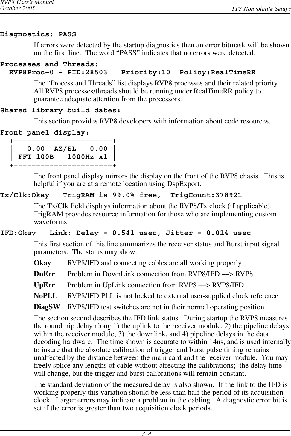
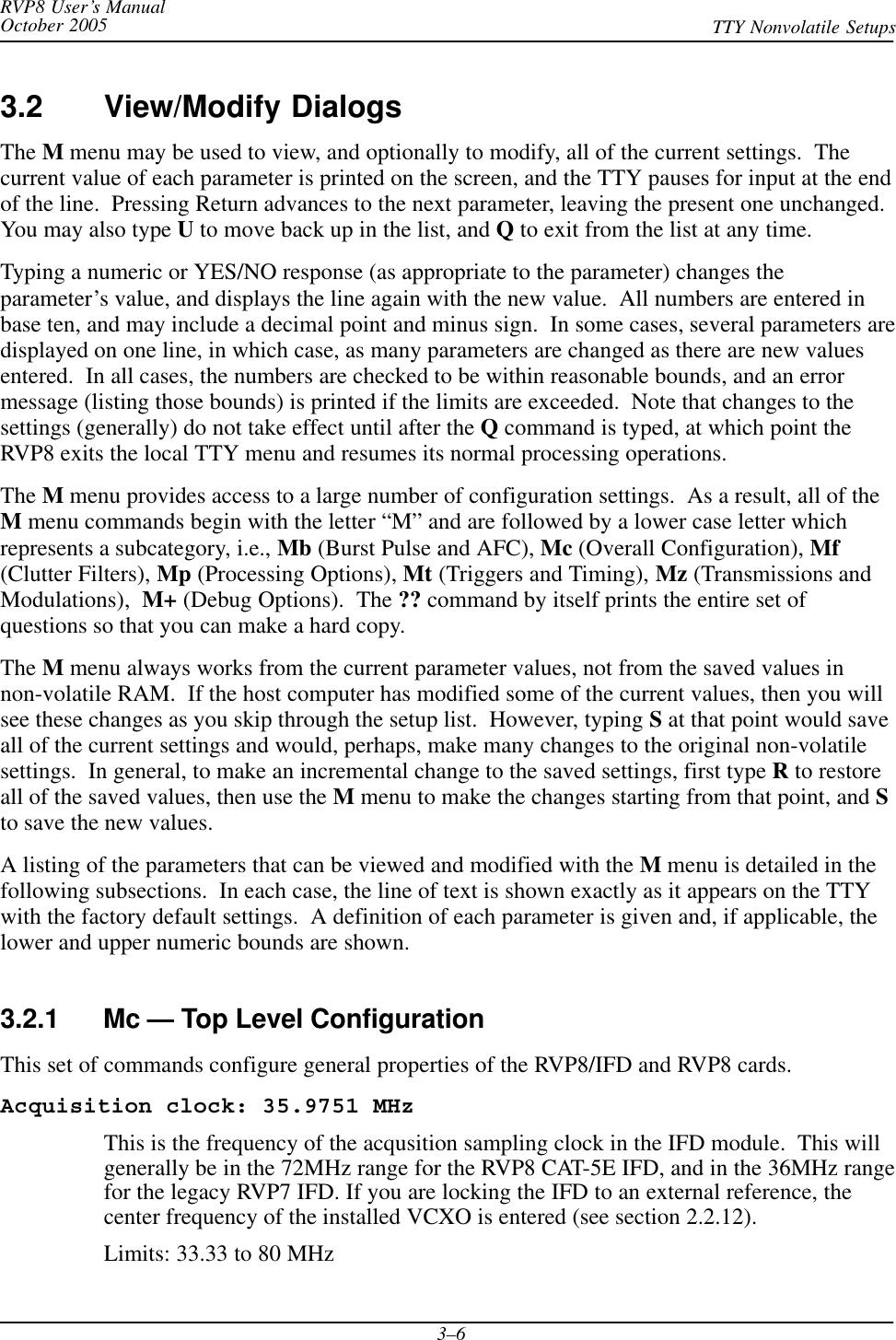
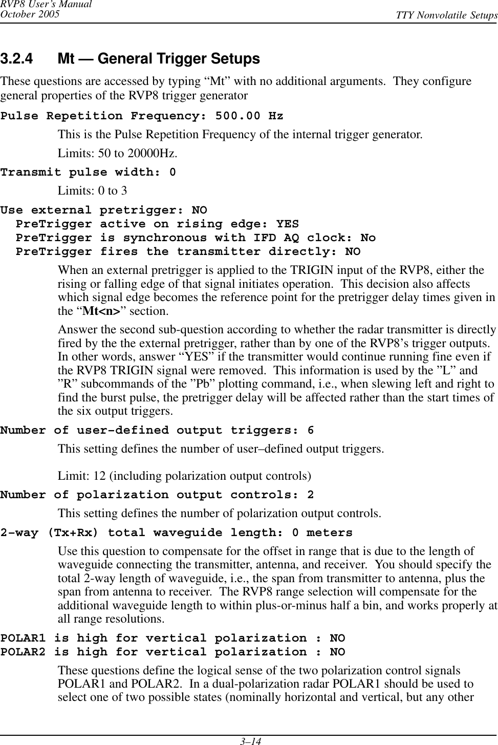
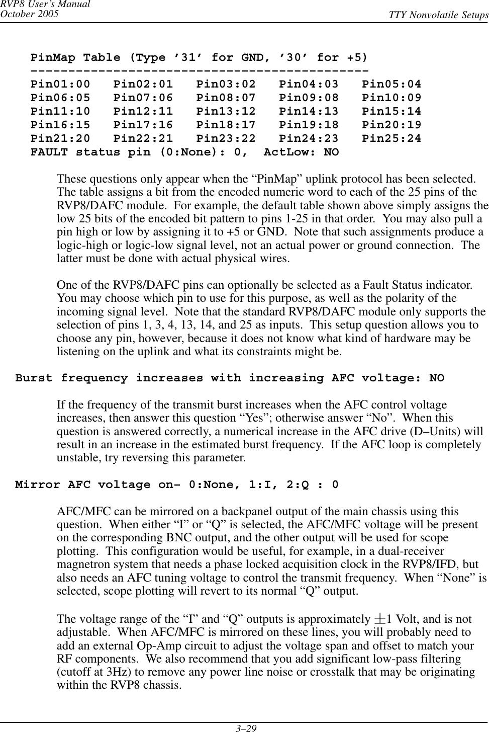
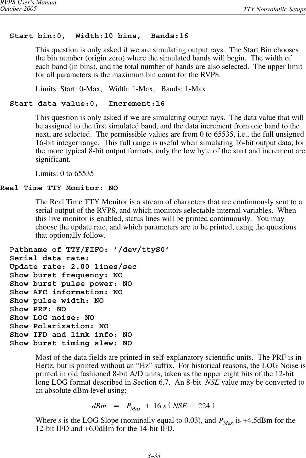
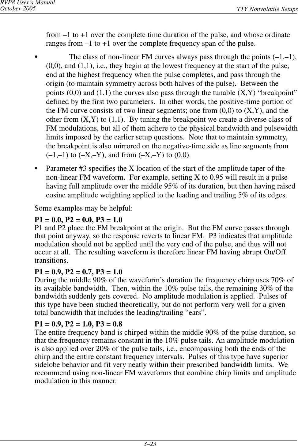
![RVP8 User’s ManualOctober 2005 TTY Nonvolatile Setups3–21Transmitter phase switch point: –1.00 usecThis is the transition time of the RVP8’s phase control output lines during randomphase processing modes. The switch point should be selected so that there isadequate settling time prior to the burst/COHO phase measurement on each pulse.This question only appears if the PHOUT[0:7] lines are actually configured for phasecontrol (See Section 3.2.1).Limits: –500 to 500 msec.Polarization switch point for POLAR1: –1.00 usecPolarization switch point for POLAR2: 1.00 usecThe RVP8’s POLAR1 and POLAR2 digital output lines control the polarizationswitch in a dual-polarization radar. During data processing modes in which thepolarization alternates from pulse to pulse, the transition points of these controlsignals are set by these two questions. The values are in microseconds relative torange zero; the same units used to define the start times of the six user triggers. Thelogical sense of POLAR1 and POLAR2 is set by questions described in Section 3.2.4.Limits: –500 to 500 msec.3.2.5.1 Special Options for Tx SynthesisSeveral of the dialogs described in the previous section will be modified when the RVP8 isequipped with an RVP8/Tx Digital Transmitter Card that has been configured for Tx waveformsynthesis in the Mz menu. In this case, each of the RVP8’s four “pulsewidths” can select anentirely different type of transmit waveform and associated matched receiver.For example, PW-0 and PW-1 could transmit conventional 0.5msec and 2.0msec CW pulses thatare received using the bandpass filters described in Section 3.2.5. But within this same system,PW-2 and PW-3 could be further configured as, perhaps, 20msec and 40msec compressednon-linear FM waveforms. This makes it very easy for application software such as ascope totransparently switch between radically different Tx waveforms simply by requesting a different“pulsewidth” for each one.The following questions will appear in the Mt<n> menu (immediately after the Range MaskSpacing question) when digital Tx waveforms are being synthesized.Tx Waveform – 0:CWPulse, 1:LinFM, 2:NLFM : 2The RVP8 supports three standard Tx waveforms: a conventional fixed-frequencyCW pulse, a linear FM chirp, and non-linear FM. The CWPulse can be used as apulsed Doppler waveform in all the same ways that a Klystron or Magnetron systemhaving a traditional pulse forming network would be used. The linear and non-linearFM waveforms, however, are compressed pulses that are intended to be transmittedby a wide-bandwidth Klystron/TWT/SolidState amplifier.Note: The RVP8 internal APIs permit code developers to create arbitrary waveformsfor transmission. The three types mentioned above are the out-of-the-box selectionsthat are standard on all RVP8 processors.](https://usermanual.wiki/Baron-Services/DSSR-250C.TTY-Nonvolatile-Setups/User-Guide-670863-Page-21.png)
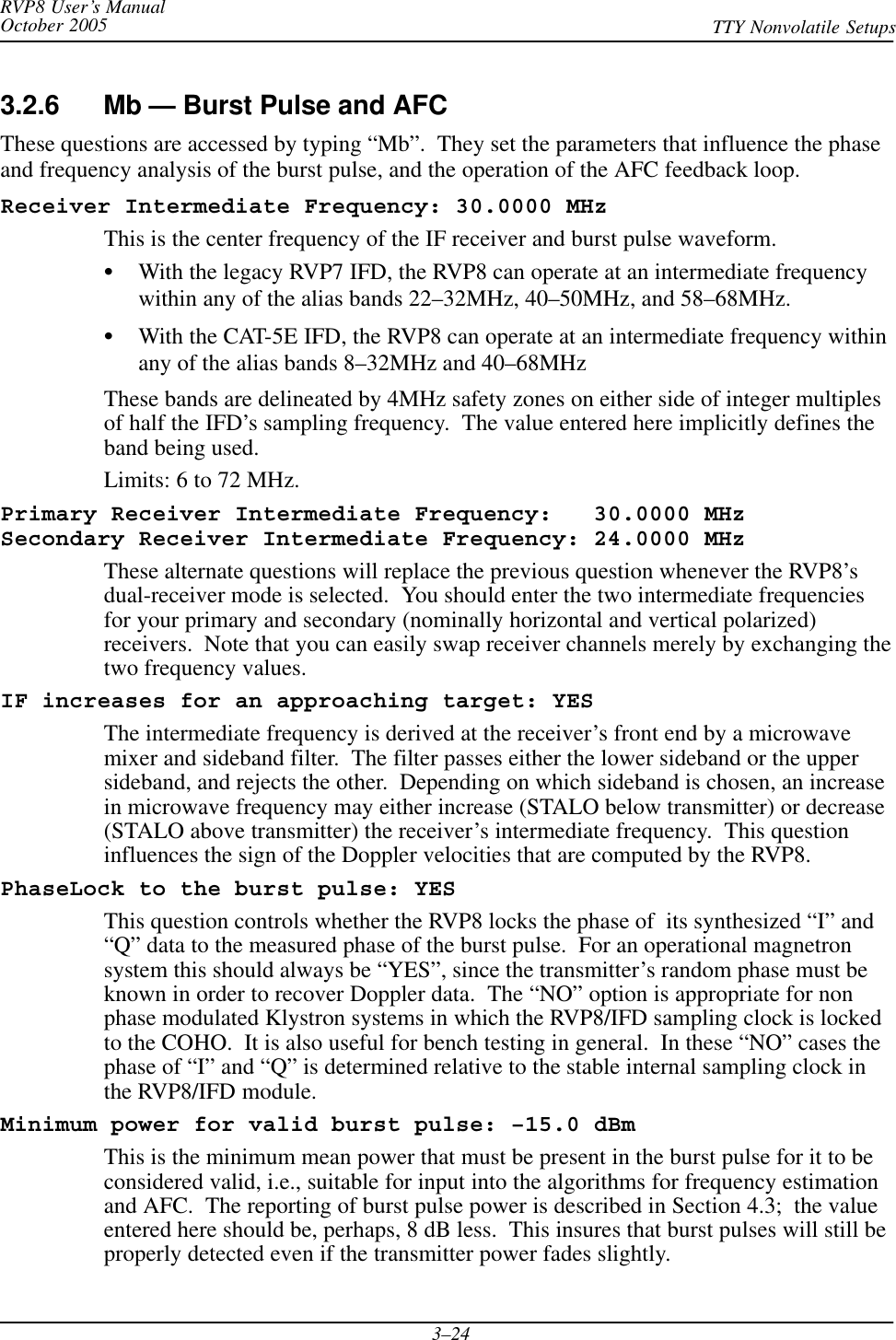
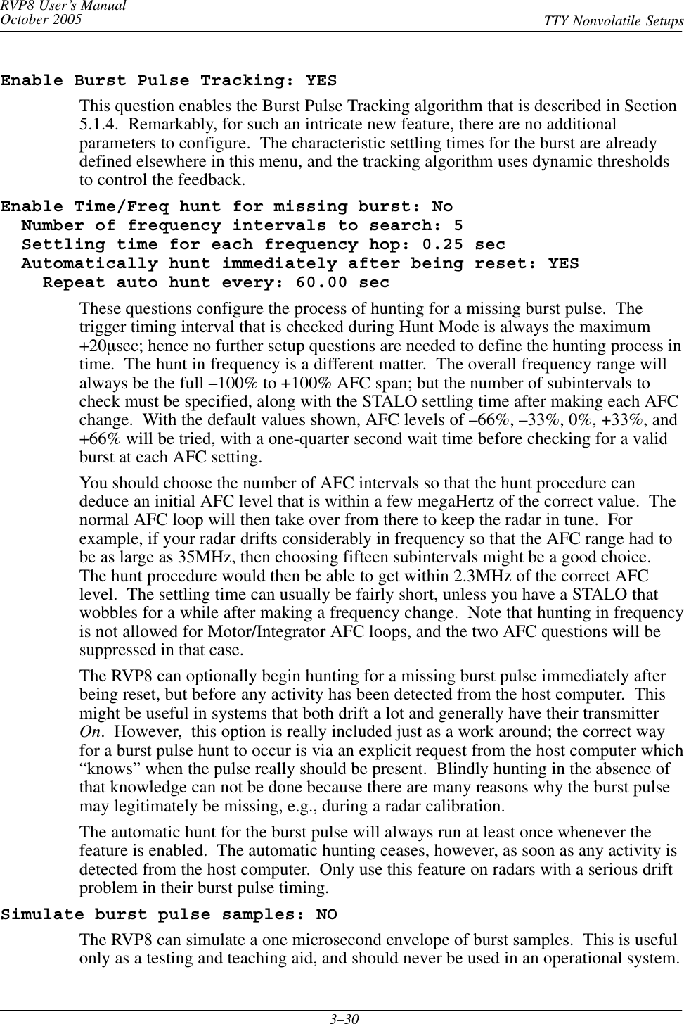
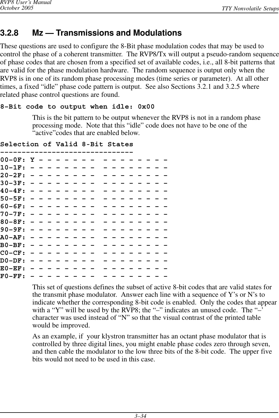
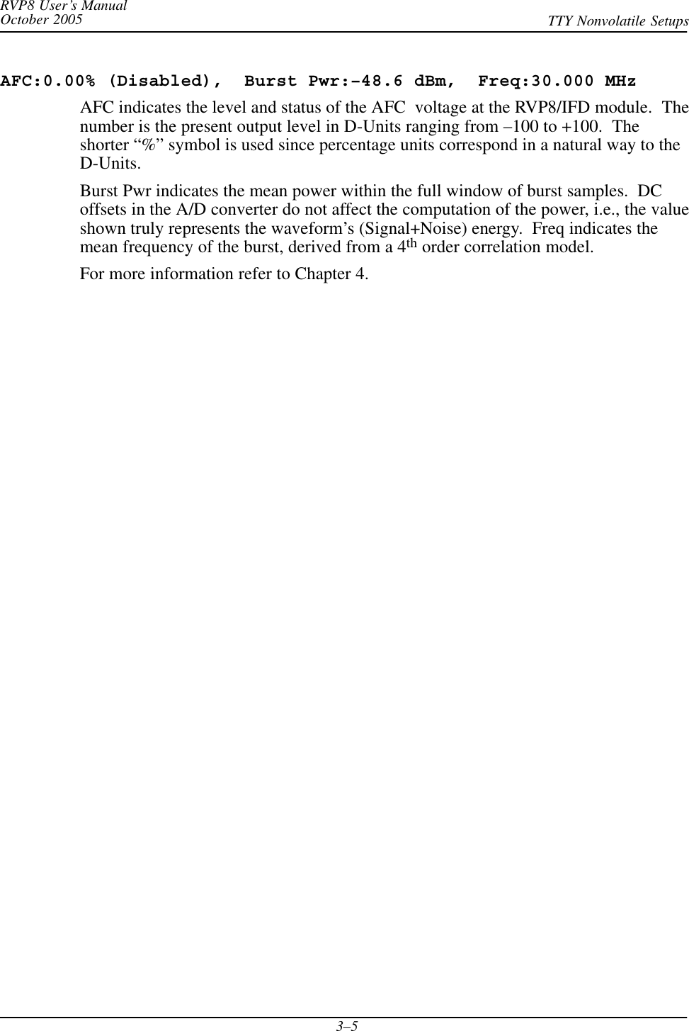
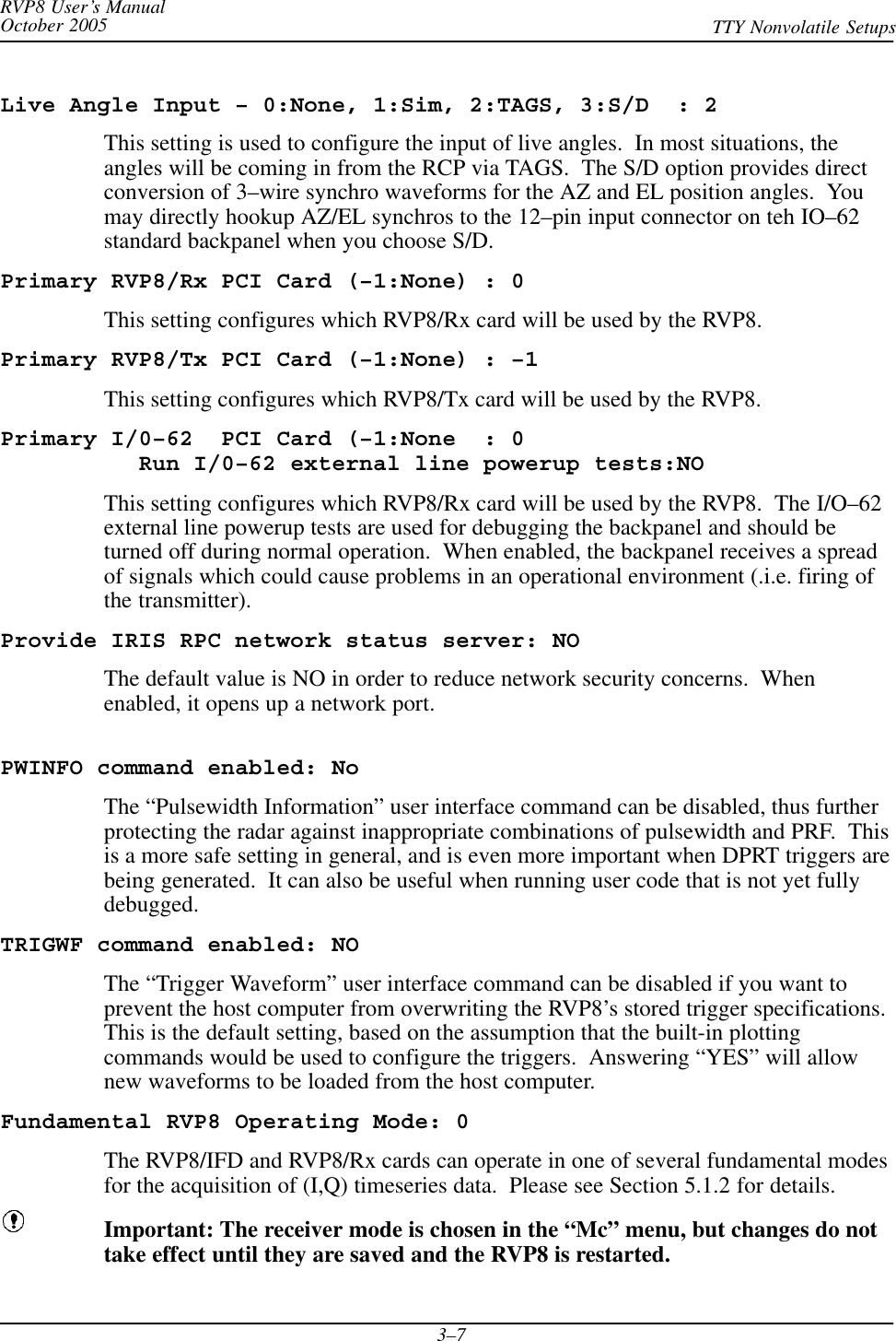
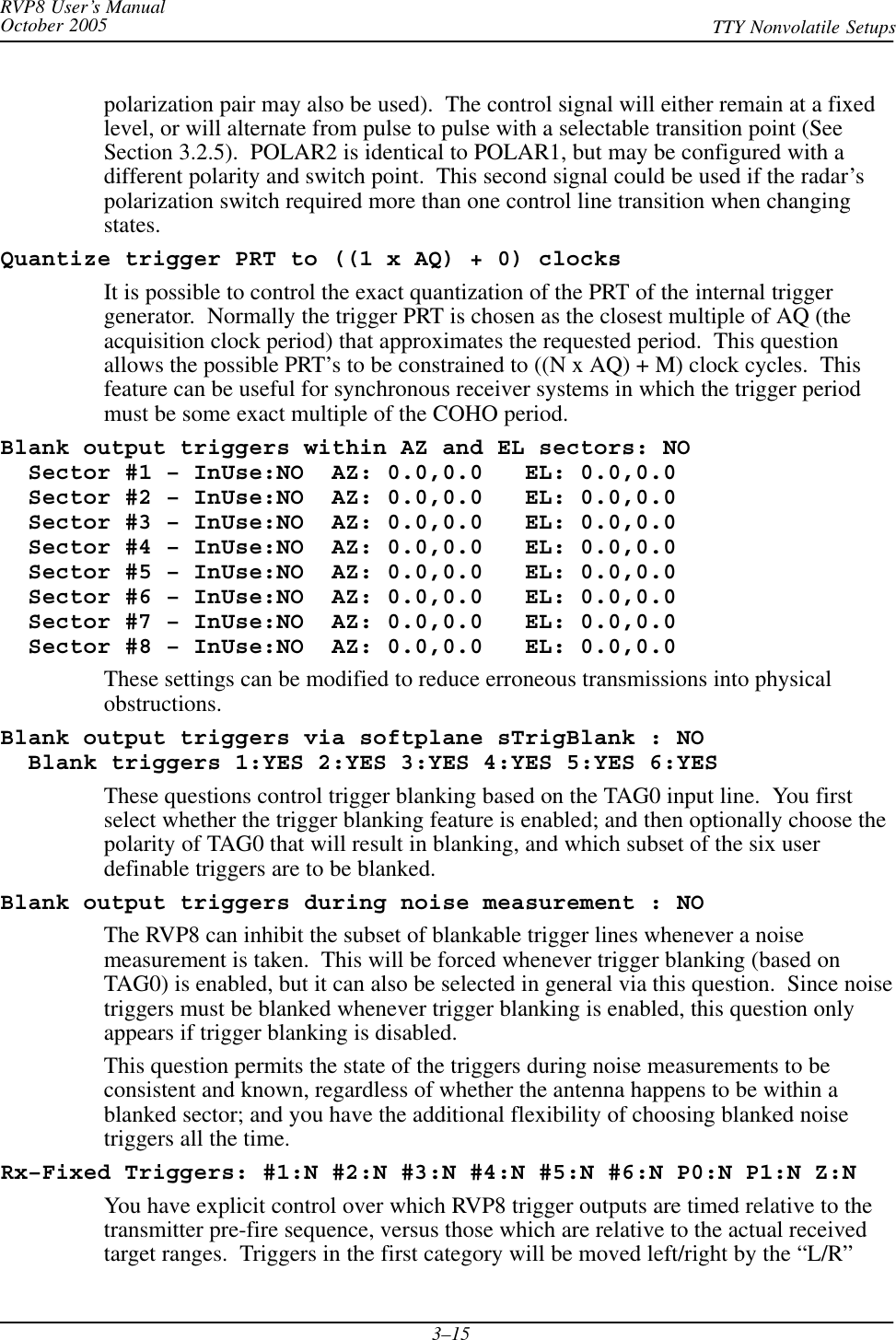
![RVP8 User’s ManualOctober 2005 TTY Nonvolatile Setups3–28 AFC span– [–100%,+100%] maps into [ –32768 , 32767 ] AFC format– 0:Bin, 1:BCD, 2:8B4D: 0, ActLow: NO AFC uplink protocol– 0:Off, 1:Normal, 2:PinMap : 1The RVP8’s implementation of AFC has been generalized so that there is nodifference between configuring an analog loop and a digital loop. The AFC feedbackloop parameters are setup the same way in each case; the only difference being themodel for how the AFC information is made available to the outside world. Manytypes of interfaces and protocols thus become possible according to how these threequestions are answered. AFC output follows these three steps:SThe internal feedback loop uses a conceptual [–100%,+100%] range of values.However, this range may be mapped into an arbitrary numeric span for eventualoutput. For example, choosing the span from –32768 to +32767 would result in16-bit AFC, and 0 to 999 might be appropriate for 3-digit BCD; but any otherspan could also be selected from the full 32-bit integer range.SNext, an encoding format is chosen for the specified numeric span. The result ofthe encoding step is another 32-bit pattern which represents the above numericvalue. SIGMET will make an effort to include in the list of supported formats allcustom encodings that our customers encounter from their vendors.SAvailable formats include straight binary, BCD, and mixed-radix formats thatmight be required by a specialized piece of equipment. The “8B4D” formatencodes the low four decimal digits as four BCD digits, and the remaining upperbits in binary. For example, 659999 base-10 would encode into 0x00419999Hex.SFinally, an output protocol is selected for the bit pattern that was produced byencoding the numeric value. The bits may be written to the eight RVP8backpanel RS232 outputs, or sent on the uplink as a value to be received by theRVP8/IFD and converted to an analog voltage. Yet another option is for the bitsto be sent on the uplink and received by the DAFC, which supports arbitraryremapping of its output pins.To summarize: the internal AFC feedback level is first mapped into an arbitrarynumeric span, then encoded using a choice of formats, and finally mapped into anarbitrary set of pins for digital output. We are hopeful that this degree of flexibilitywill allow easy hookup to virtually any STALO synthesizer that one might encounter.](https://usermanual.wiki/Baron-Services/DSSR-250C.TTY-Nonvolatile-Setups/User-Guide-670863-Page-28.png)