Bauer Compressors B-RFID RF ID Reader in Air Fill Station User Manual Part 3
Bauer Compressors, Inc RF ID Reader in Air Fill Station Users Manual Part 3
Contents
- 1. Users Manual Part 1
- 2. Users Manual Part 2
- 3. Users Manual Part 3
- 4. Users Manual Part 4
Users Manual Part 3
MNL-0021
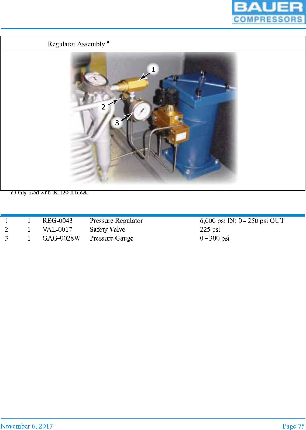
Item Qty Part No. Description Notes
Figure 3-49

UNICUS 4i
3.3.2 Trouble shooting
Trouble Cause Remedy
MNL-0021
CHAPTER 4: PURIFICATION SYSTEM
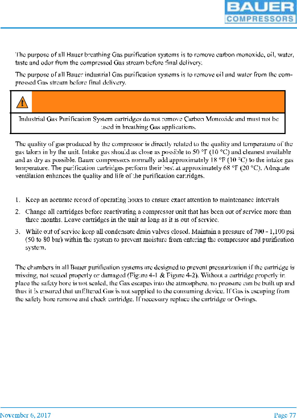
4.1 Introduction
4.1.1 General Purification System Procedures
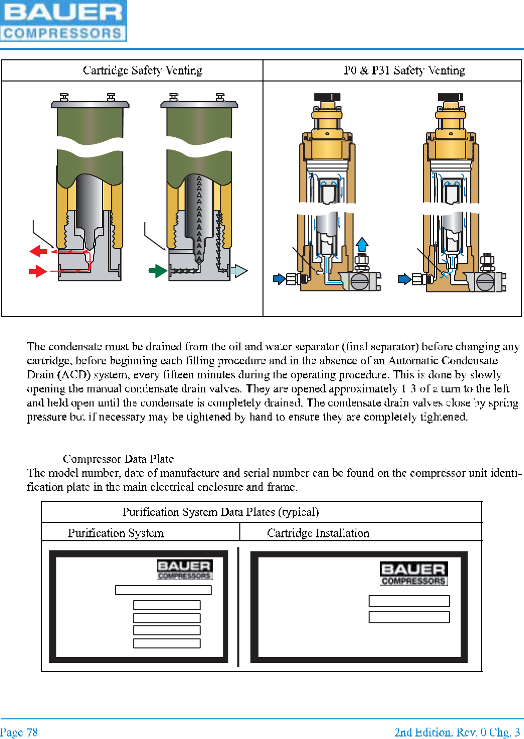
4.1.2 Chamber Safety Bore
WARNING
UNICUS 4i
4.1.3 Manual Condensate Drainage
4.1.4 Model, Serial Number and Part Number Identification
4.1.4.1
Figure 4-1 Figure 4-2
Figure 4-3
Safety
Vent
(no leak)
Cartridge Installed
correctly
Safety
Vent
(leaking)
No Cartridge Installed
or Installed incorrectly
C ar tridge In sta lled
C or rectl y
No Car tridge o r Instal led
Incorrectl y
Safety
Ve nt
Safety
Vent
CARTRIDGE FOR
CARTRIDGE NO.
LBL-0044
CARTRIDGE TO BE
INSTALLED
132 8 Azale a Ga rden R oad - Norfolk Virginia 23502-1 944
Phone : (757) 855-6006 Fa x: (757) 855-82 24
MODEL NO .
MAX. PRE SS URE
AIR PROC ESSED
O-RING
BACK- UP RIN G
psig
cu. ft.
LBL-0191
PUR IFICATION
SYSTEM
MNL-0021
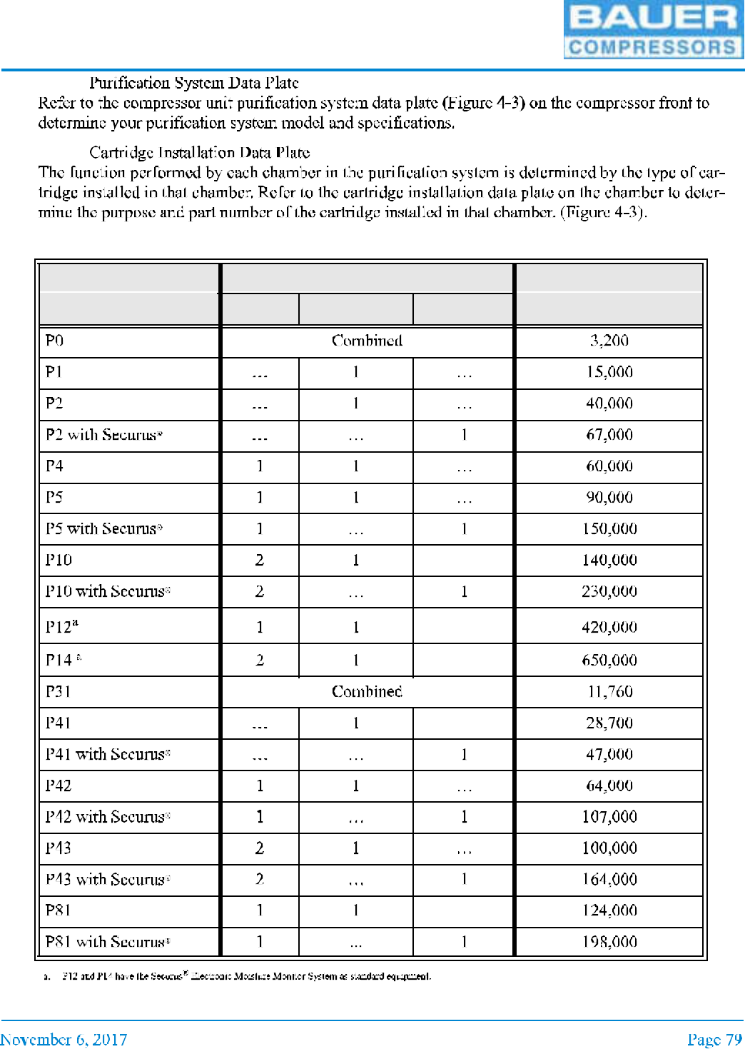
4.1.4.2
4.1.4.3
4.1.5 Purification System Configurations
Purification System Number and Type of Cartridges Processing Capacity
Dryer Purification Securus
®
cubic ft (ft)3
UNICUS 4i
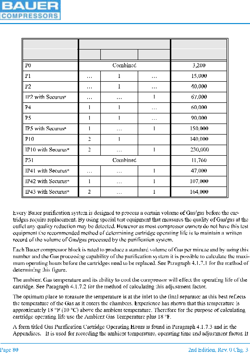
4.1.6 Industrial Purification System Configurations
4.1.7 Cartridge Operating Life
Purification System Number and Type of Cartridges Processing Capacity
Dryer Purification Securus
®
cubic ft (ft)3
MNL-0021
4.1.7.1
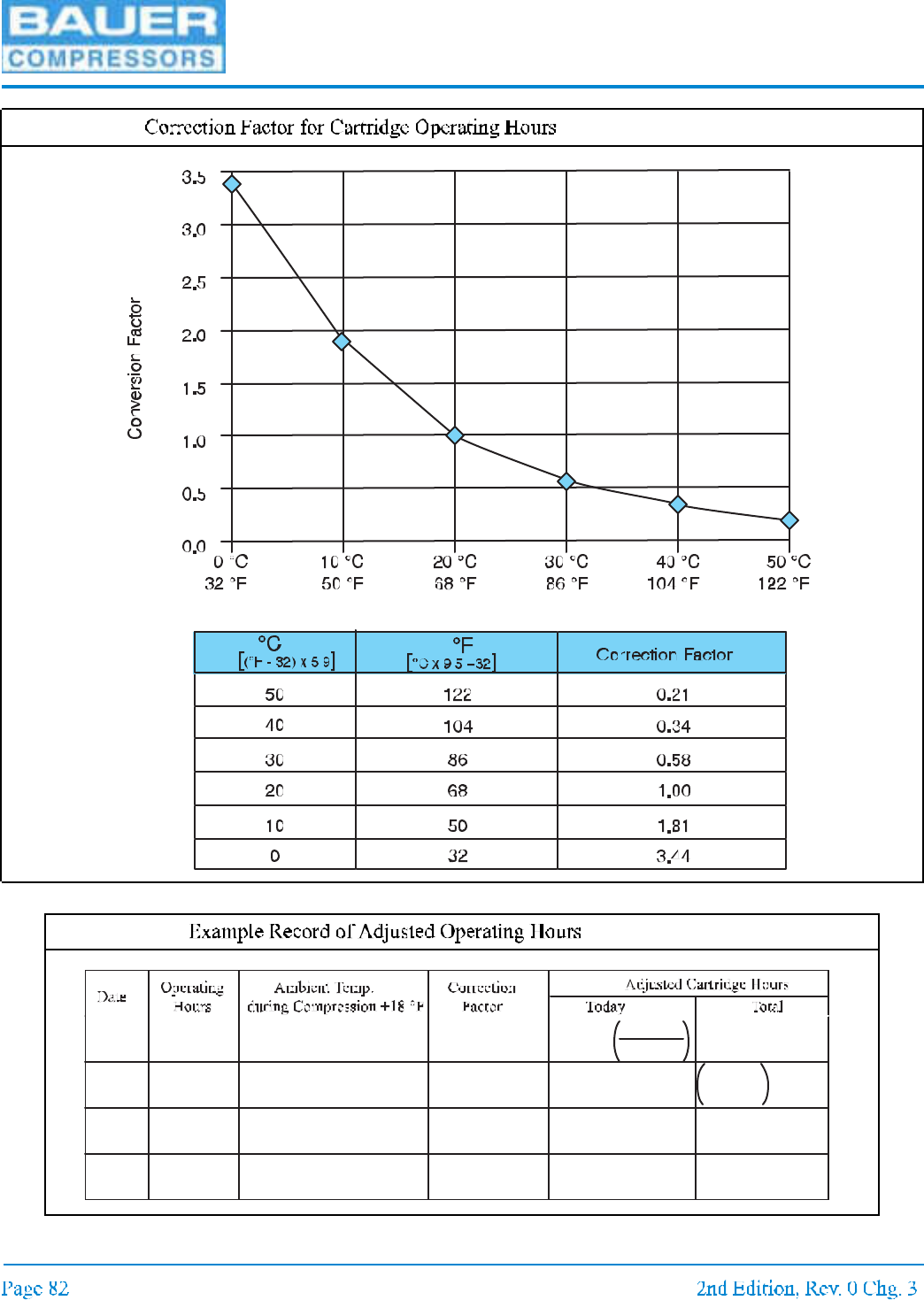
4.1.7.2
UNICUS 4i
Figure 4-4
Figure 4-5
10/19/04 8 92°F
(33 °C)
0.5 16.00 16.00
11/01/04 4 45°F
(7.2 °C)
2.25 1.78 17.78
Op hrs
Corr. factor
Total hrs
+Today hr s
MNL-0021
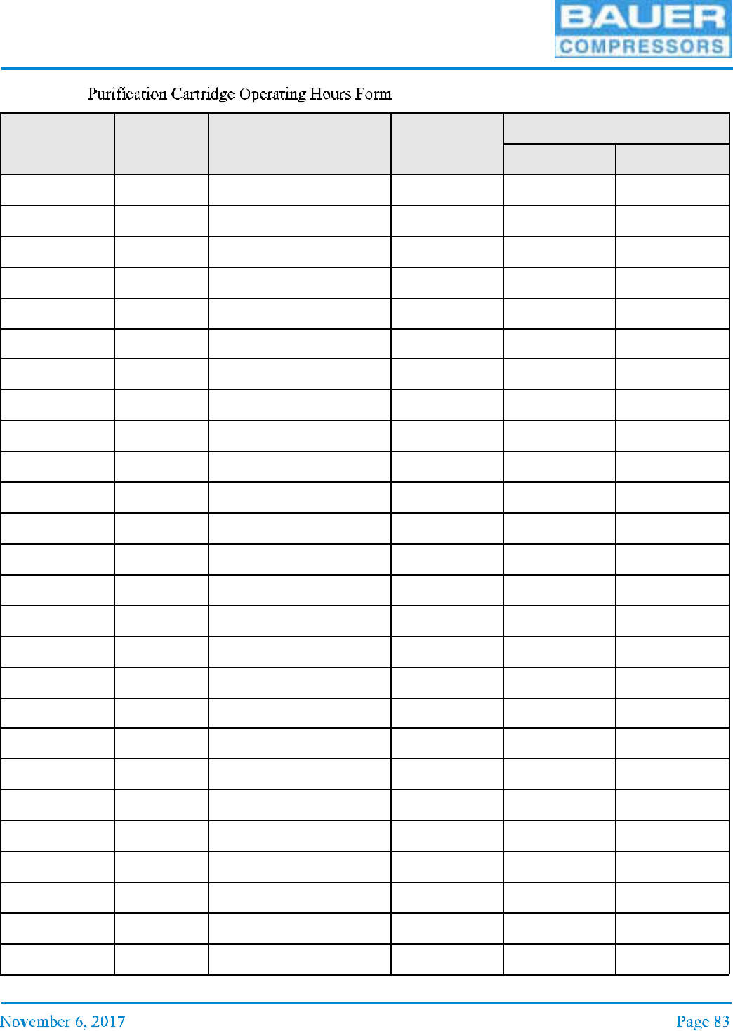
4.1.7.3
Date Operating
hours
Ambient temp. + 18°F
during compression
Correction
factor
Adjusted cartridge hours
Today Total
UNICUS 4i
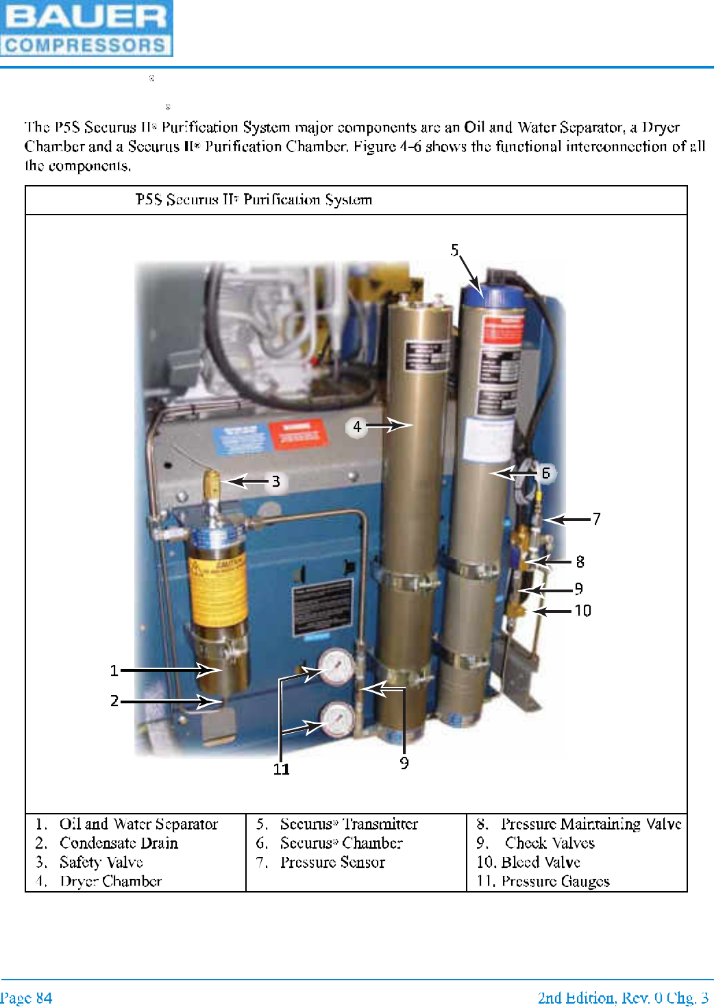
4.2 1P5S Securus II Purification System
4.2.1 P5S Securus II Purification System Major Components
Figure 4-6
MNL-0021
4.3 Component Description
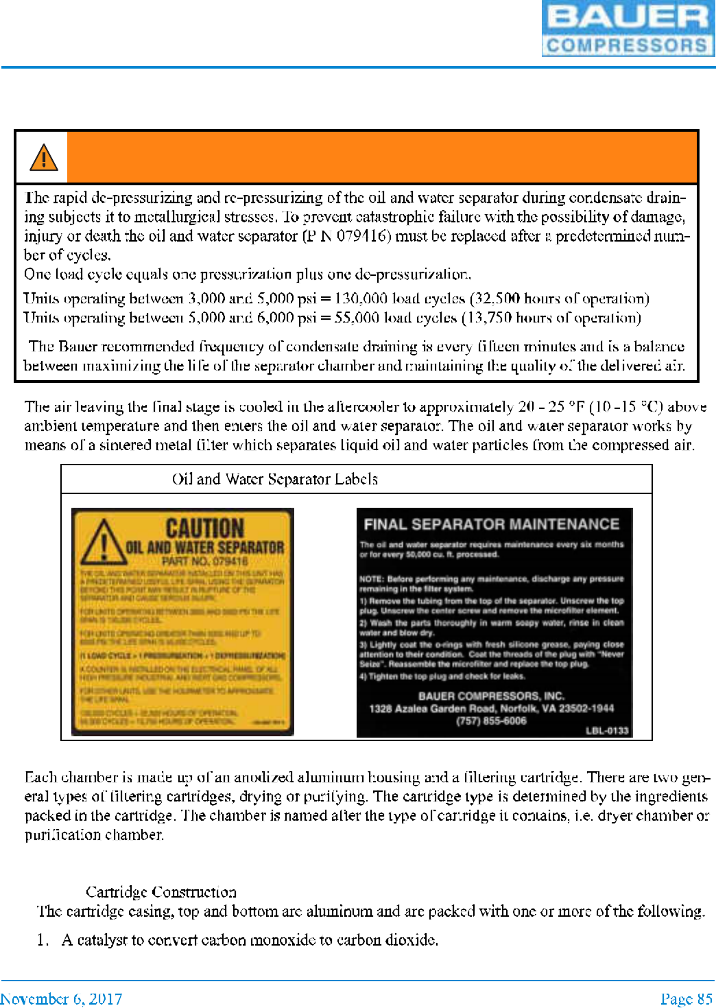
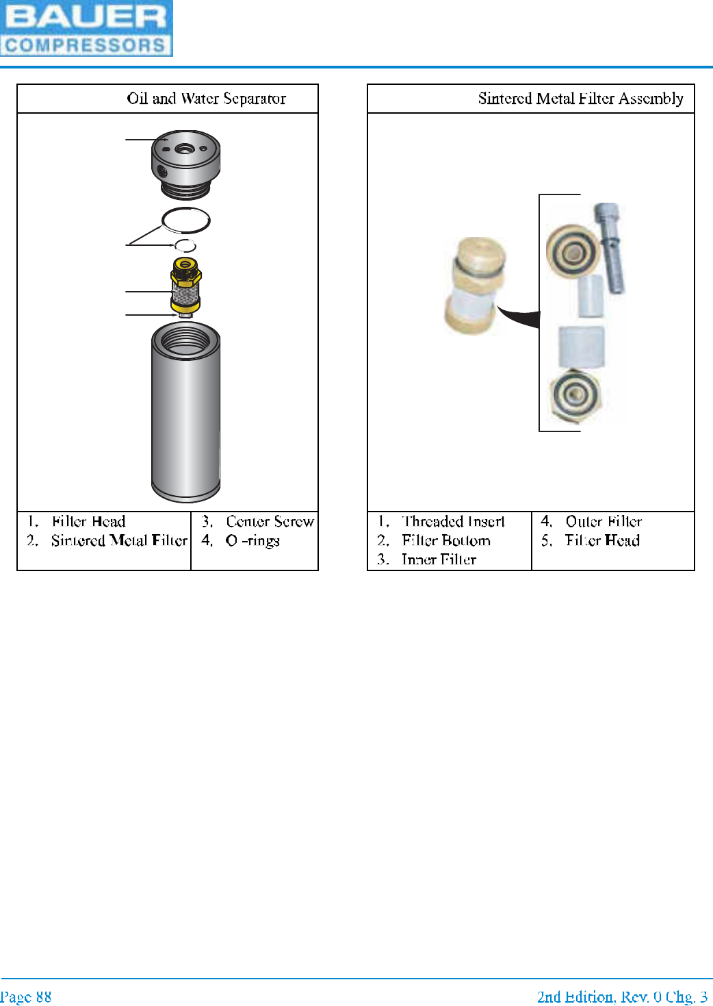
4.3.1 Oil and Water Separator
4.3.2 Chamber
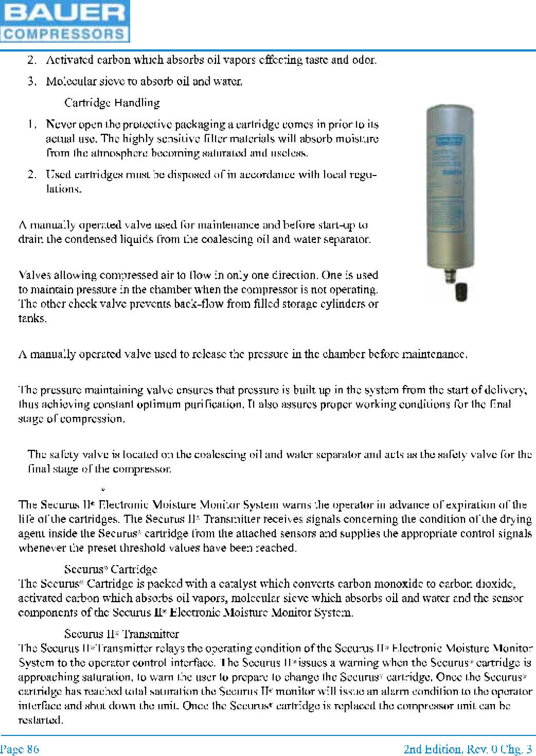
4.3.3 Cartridge
4.3.3.1
WARNING
Figure 4-7
UNICUS 4i
4.3.3.2
4.3.4 Condensate Drain Valve
4.3.5 Check Valves
4.3.6 Bleed Valve
4.3.7 Pressure Maintaining Valve
4.3.8 Safety Valve
4.3.9 Securus II Electronic Moisture Monitor System
4.3.9.1
4.3.9.2
Protective Cap
Purification
Cartridge
MNL-0021
4.4 Maintenance
4.4.1 Oil and Water Separator
UNICUS 4i
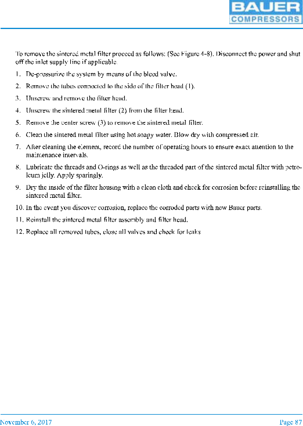
Figure 4-8 Figure 4-9
1
2
3
4
MNL-0021
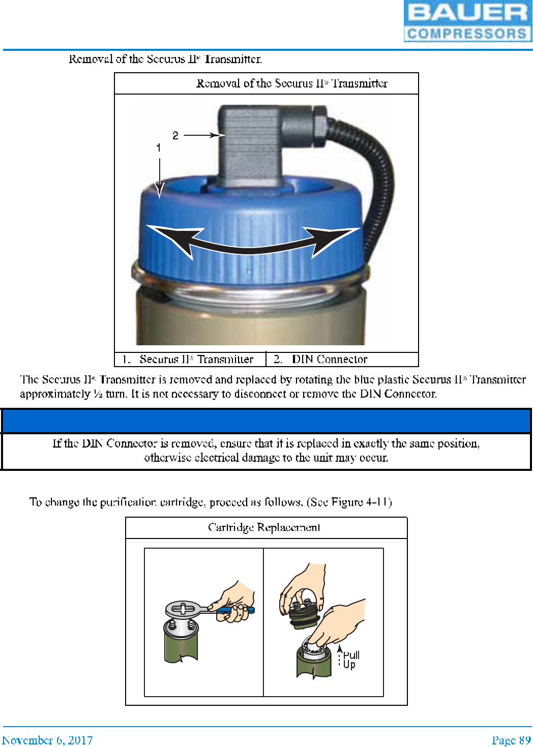
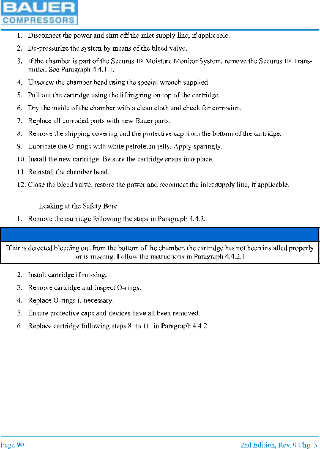
4.4.1.1
4.4.2 Cartridge Replacement
Figure 4-10
NOTICE
Figure 4-11
UNICUS 4i
4.4.2.1
NOTICE
MNL-0021
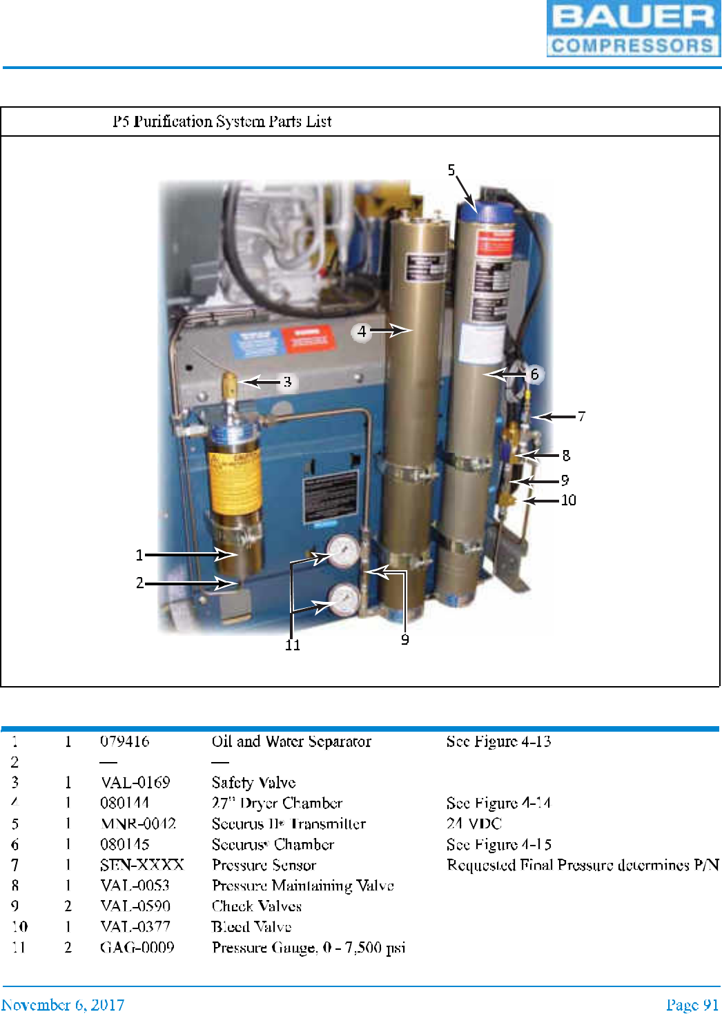
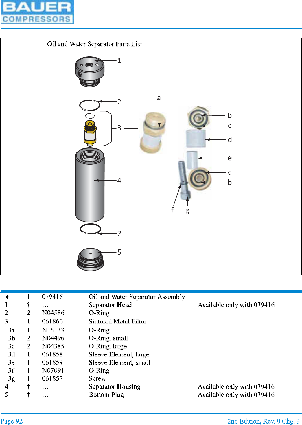
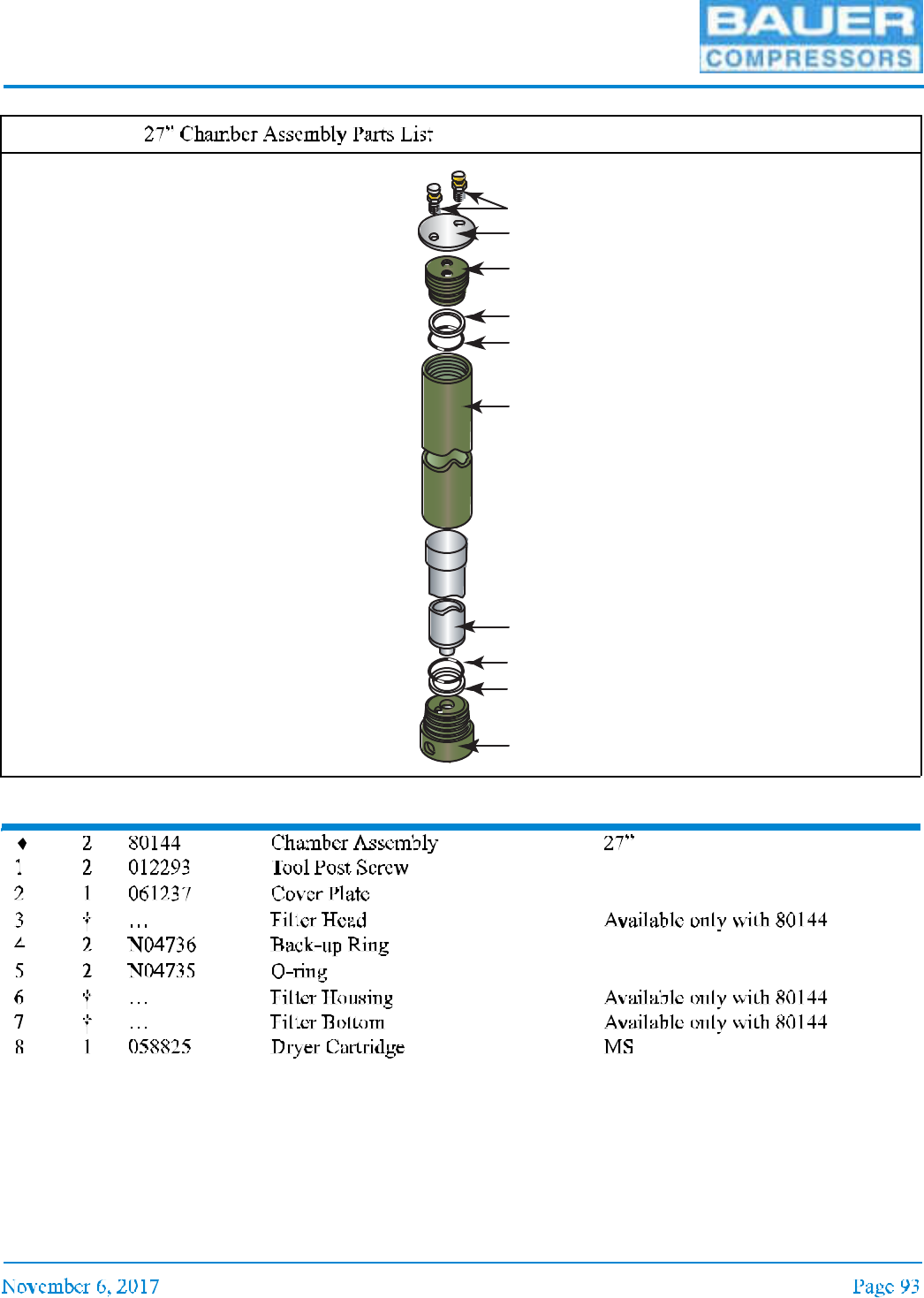
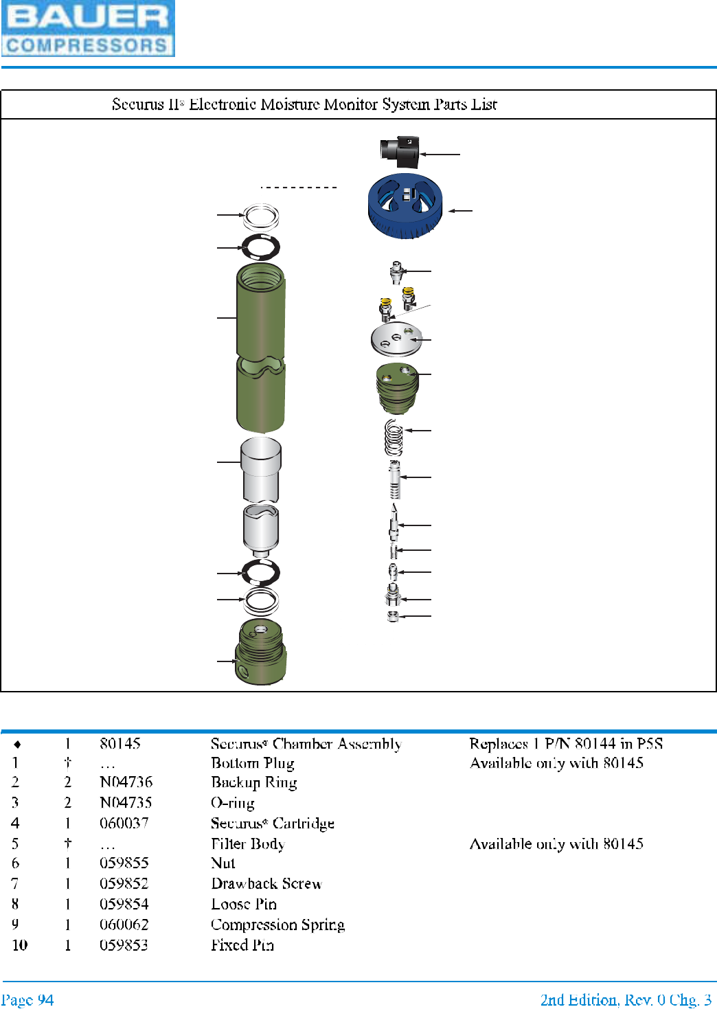
4.5 Replacement Parts List
Item Qty Part No. Description Notes
1 gauge stock, 2nd is optional
Figure 4-12
UNICUS 4i
Item Qty Part No. Description Notes
Figure 4-13
MNL-0021
Item Qty Part No. Description Notes
Figure 4-14
1
2
3
4
4
5
5
6
7
8
UNICUS 4i
Item Qty Part No. Description Notes
Figure 4-15
1
2
3
4
5
3
2
9
6
7
8
10
11
12
13
14
15
16
17
18
MNL-0021
Figure 4-15 (cont.)
Item Qty Part No. Description Notes
UNICUS 4i
CHAPTER 5: COMPRESSOR DRIVE; UNICUS 4I
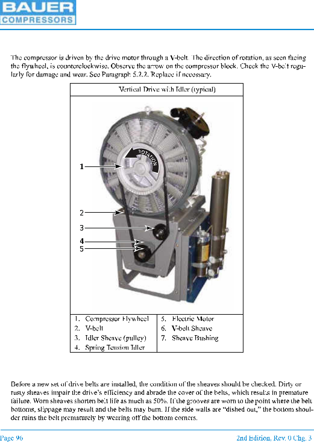
5.1 Vertical Compressor Drive
5.2 Maintenance of the V-belt and Sheaves
5.2.1 Check The Sheaves.
Figure 5-1
MNL-0021
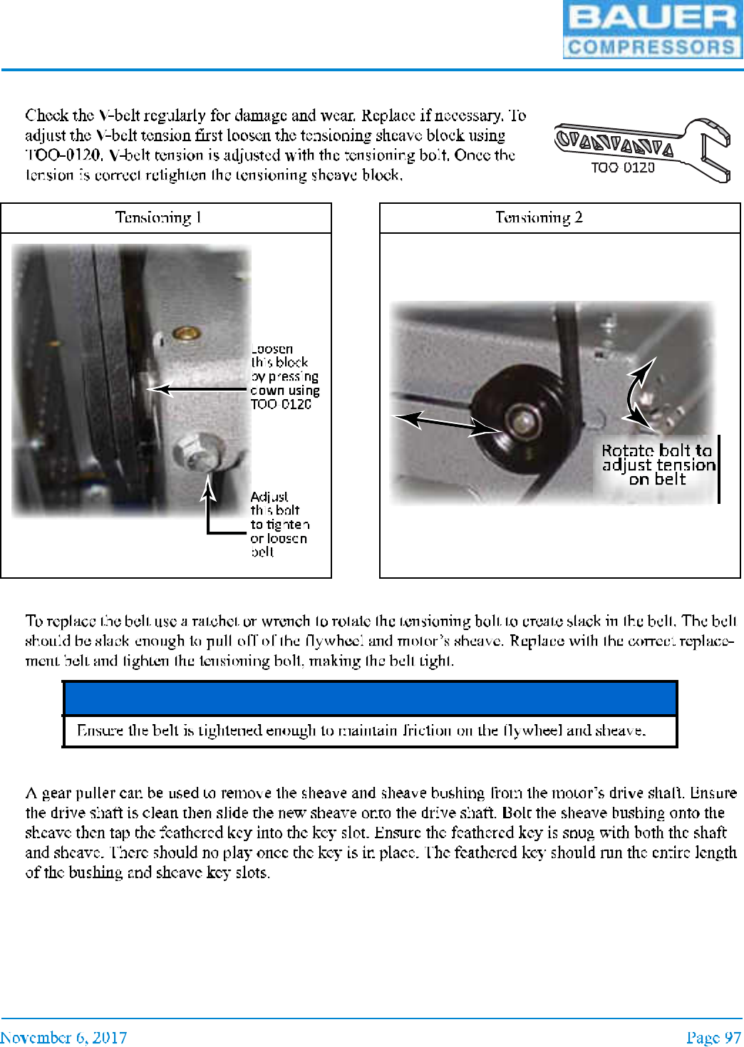
5.2.2 Check the V-belt
5.2.3 Replacing the Belt
5.2.4 Replacing the Sheave
Figure 5-2 Figure 5-3
NOTICE
UNICUS 4i
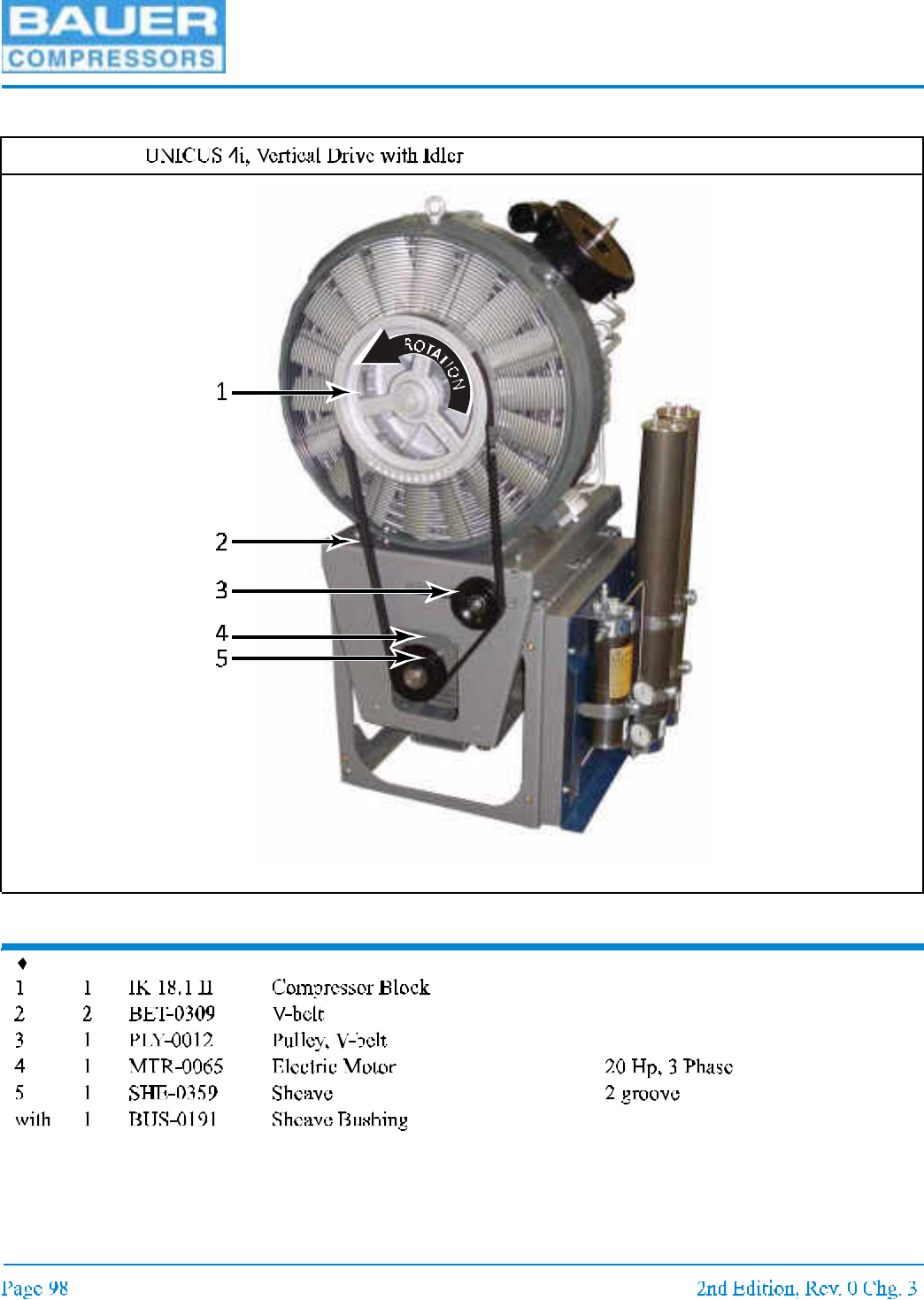
5.3 Replacement Part List
Item Qty Part No. Description Notes
UNICUS 4i - 25
Figure 5-4
MNL-0021
CHAPTER 6: ELECTRICAL PANEL, ASY-1191
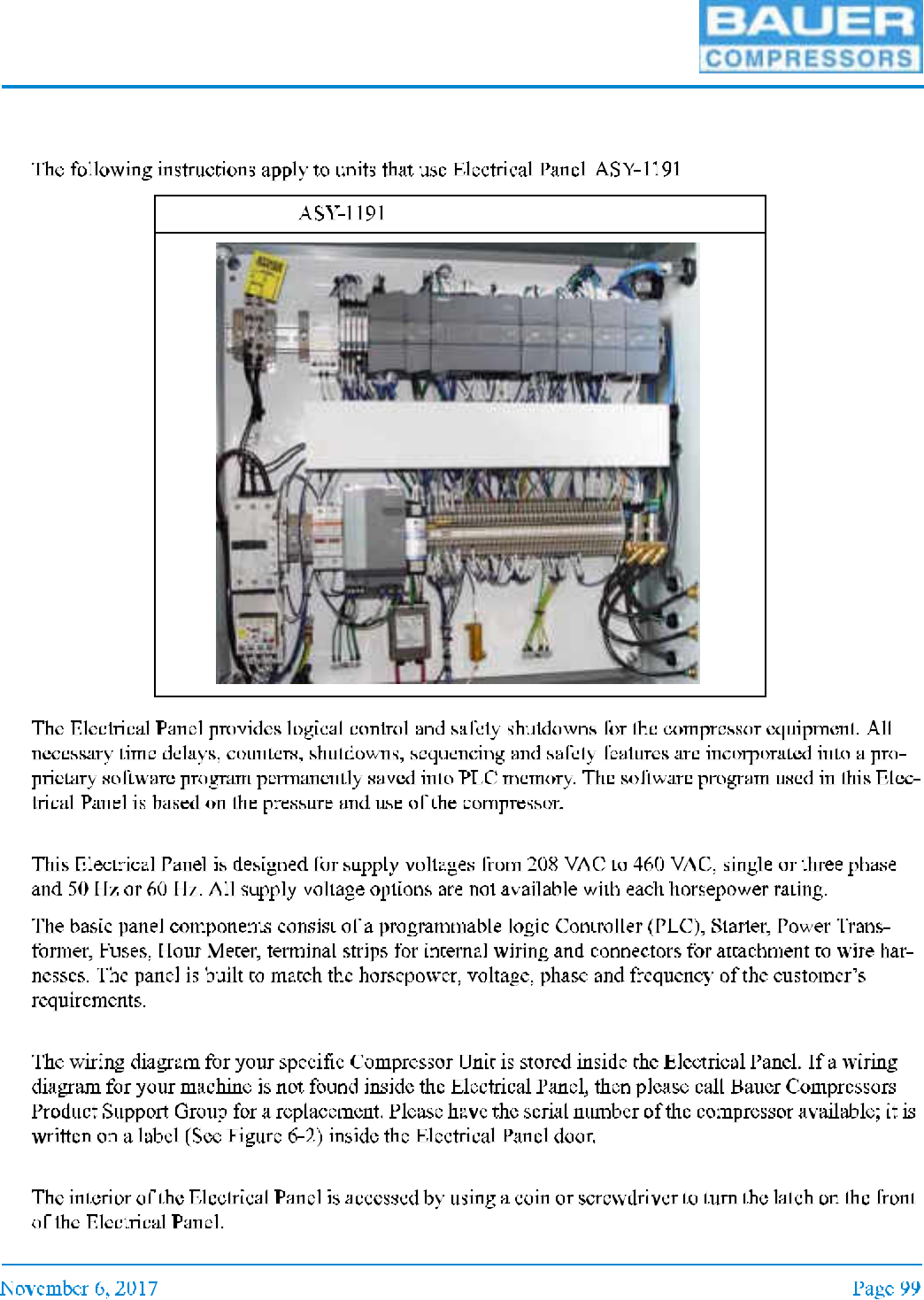
6.1 Overview
,
6.2 Electrical Panel
6.2.1 Wiring Diagram
6.2.2 Electrical Panel Interior Access
Figure 6-1

UNICUS 4i
6.3 AC Power Requirements
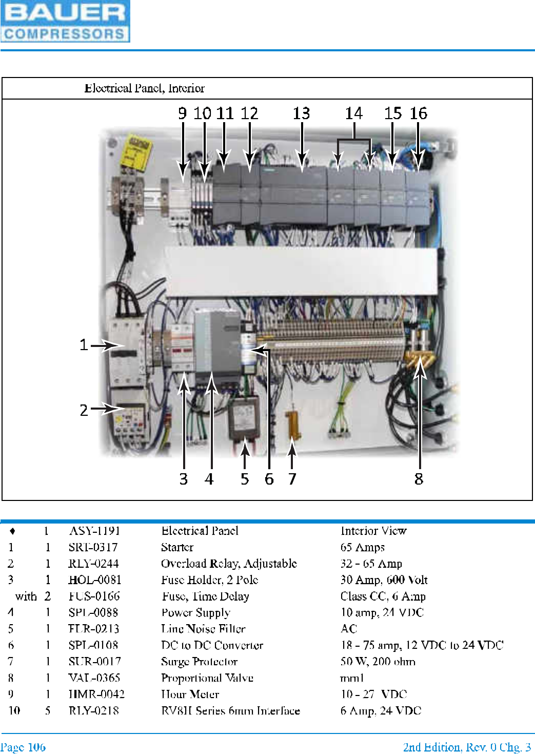
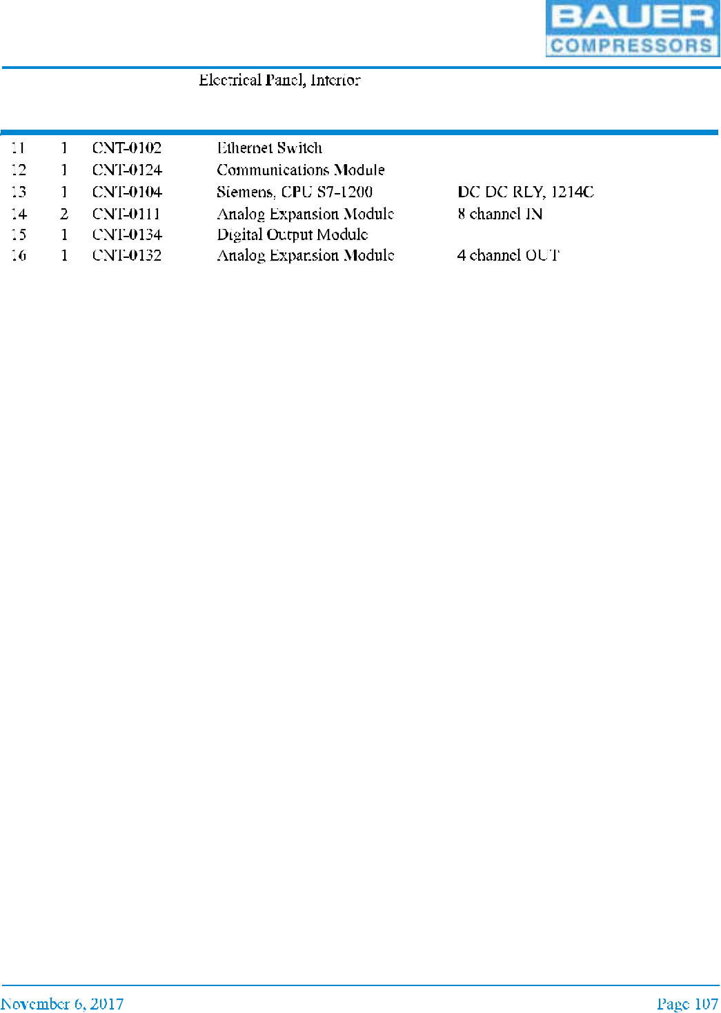
6.4 Electrical Panel Components
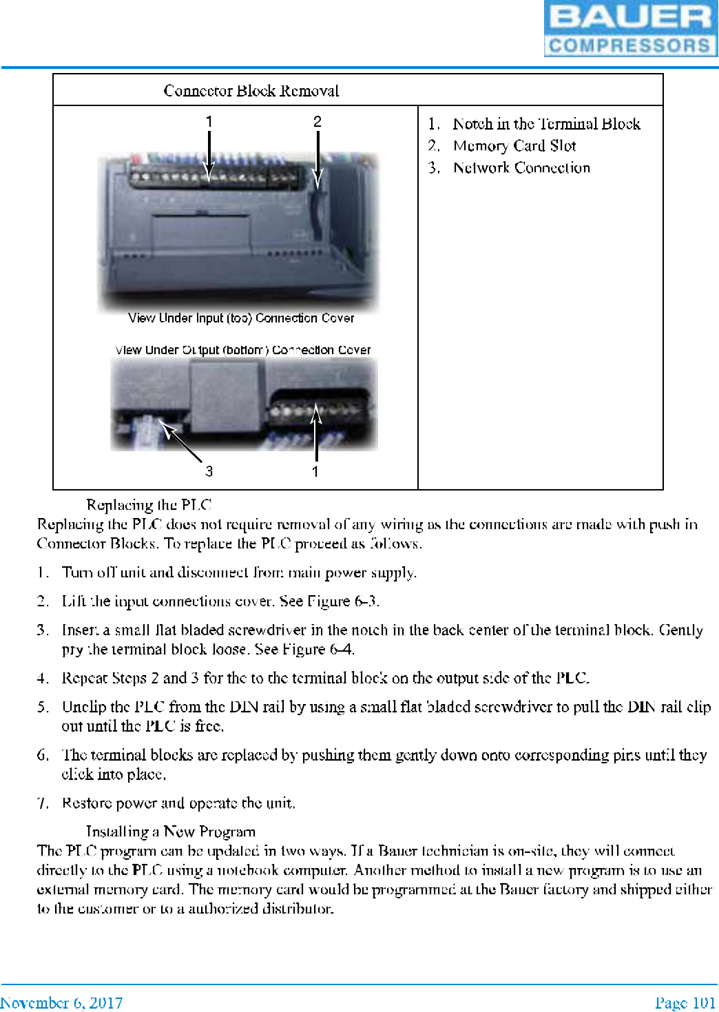
6.4.1 Programmable Logic Controller (PLC)
Figure 6-2
Figure 6-3
MNL-0021
6.4.1.1
6.4.1.2
Figure 6-4
UNICUS 4i
6.4.1.3
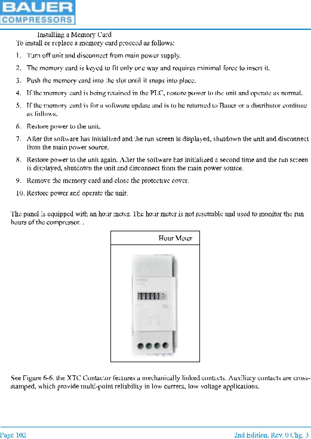
6.4.2 Hour Meter
6.4.3 Motor Starter.
Figure 6-5
MNL-0021
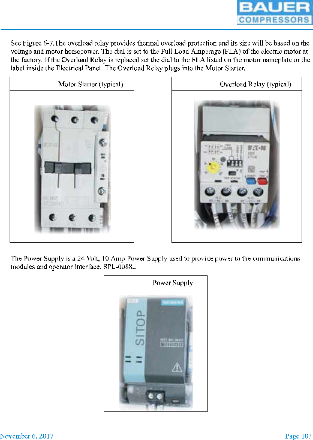
6.4.4 Overload Relay
6.4.5 Power Supply
Figure 6-6 Figure 6-7
Figure 6-8
UNICUS 4i
6.5 Alarms
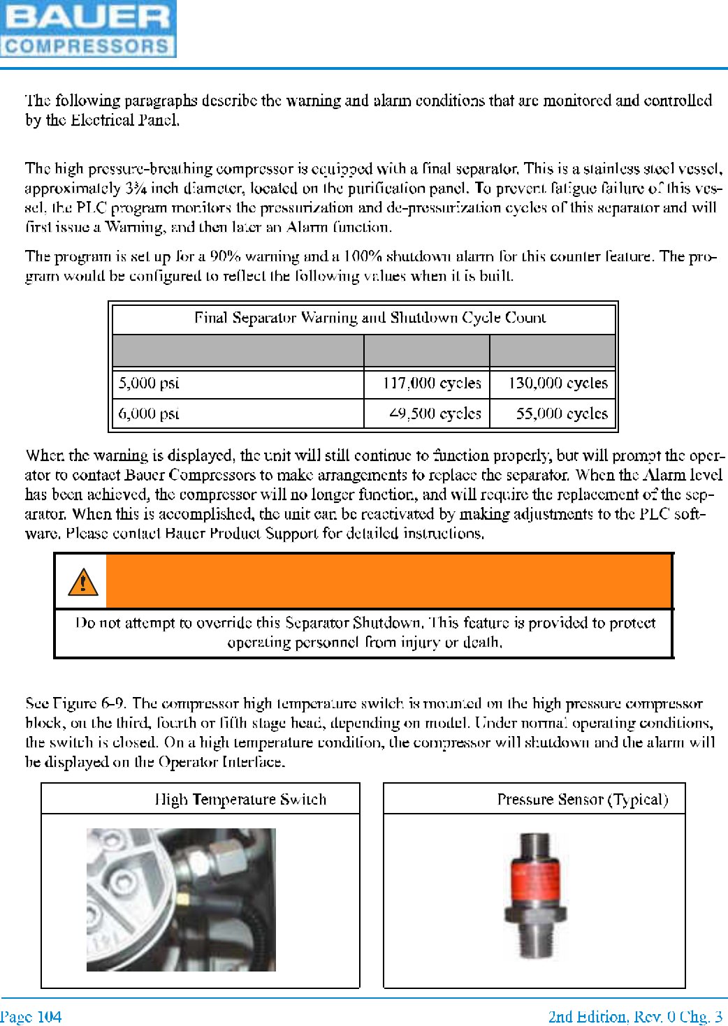
6.5.1 Final Separator Warning
6.5.2 Compressor High Temperature
Table 6-1:
Maximum Compressor Pressure Warning Shutdown
WARNING
Figure 6-9 Figure 6-10
MNL-0021
6.5.3 Compressor Low Oil Pressure
OIL PRESS TD
UNICUS 4i
6.6 Replacement Parts List
Item Qty Part No. Description Notes
Figure 6-11
MNL-0021
Figure 6-11 (cont.)
Item Qty Part No. Description Notes
UNICUS 4i
CHAPTER 7: RFID OPTION
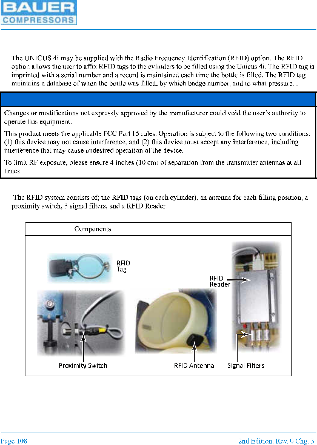
7.1 Description
7.2 Components
NOTICE
Figure 7-1
MNL-0021
7.3 Functions
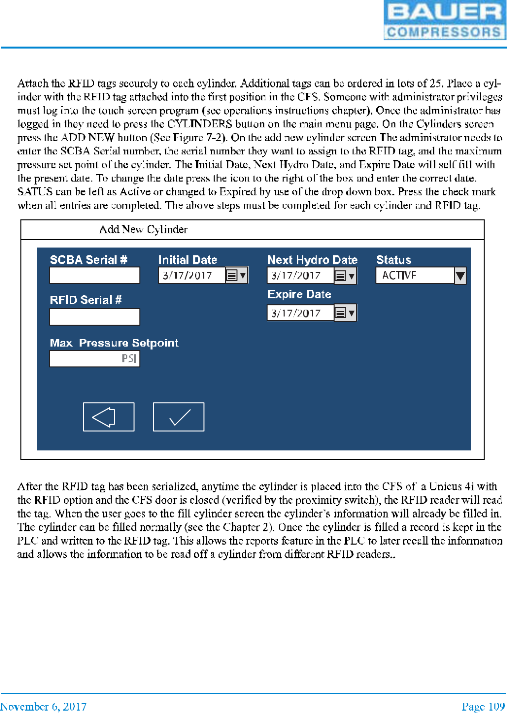
7.3.1 Assigning the Cylinder
7.3.2 Filling the Cylinder with RFID Option
Figure 7-2
UNICUS 4i
7.4 Replacement Parts List
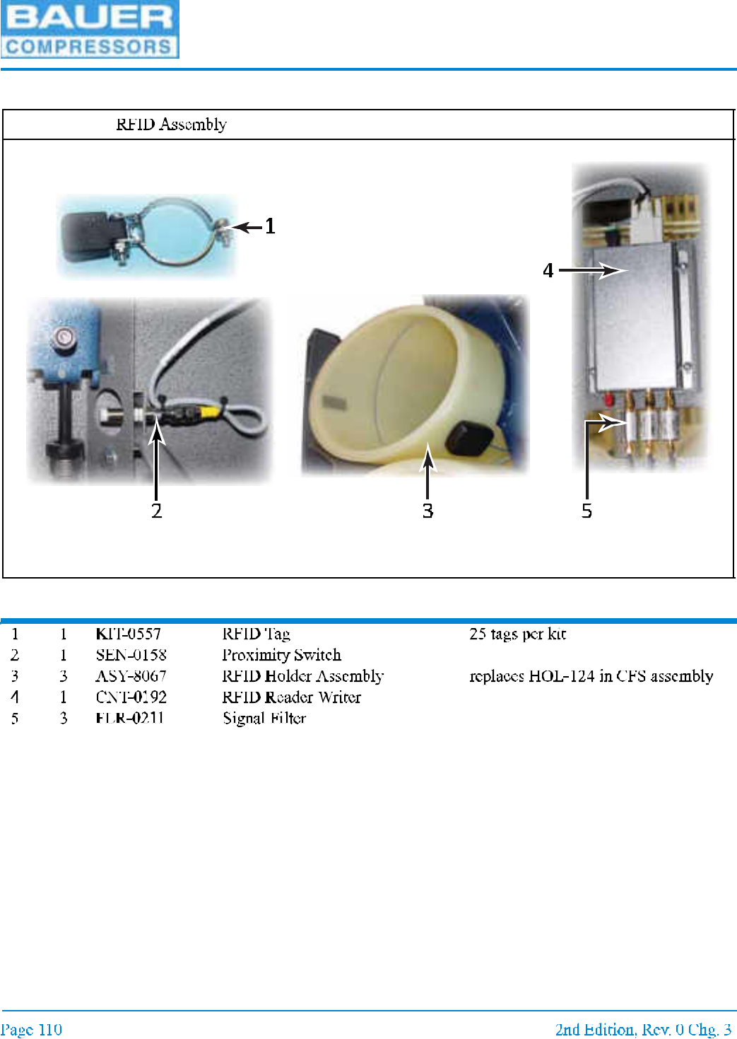
Item Qty Part No. Description Notes
Figure 7-3
MNL-0021
CHAPTER 8: ENMET GAS MONITORS
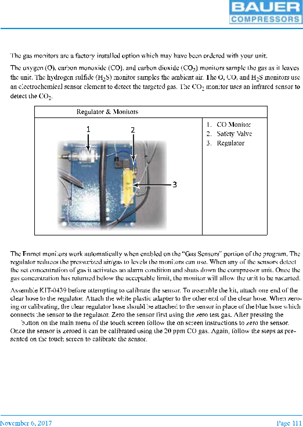
8.1 Description
8.2 Operation
Sen-
sor
Figure 8-1
UNICUS 4i
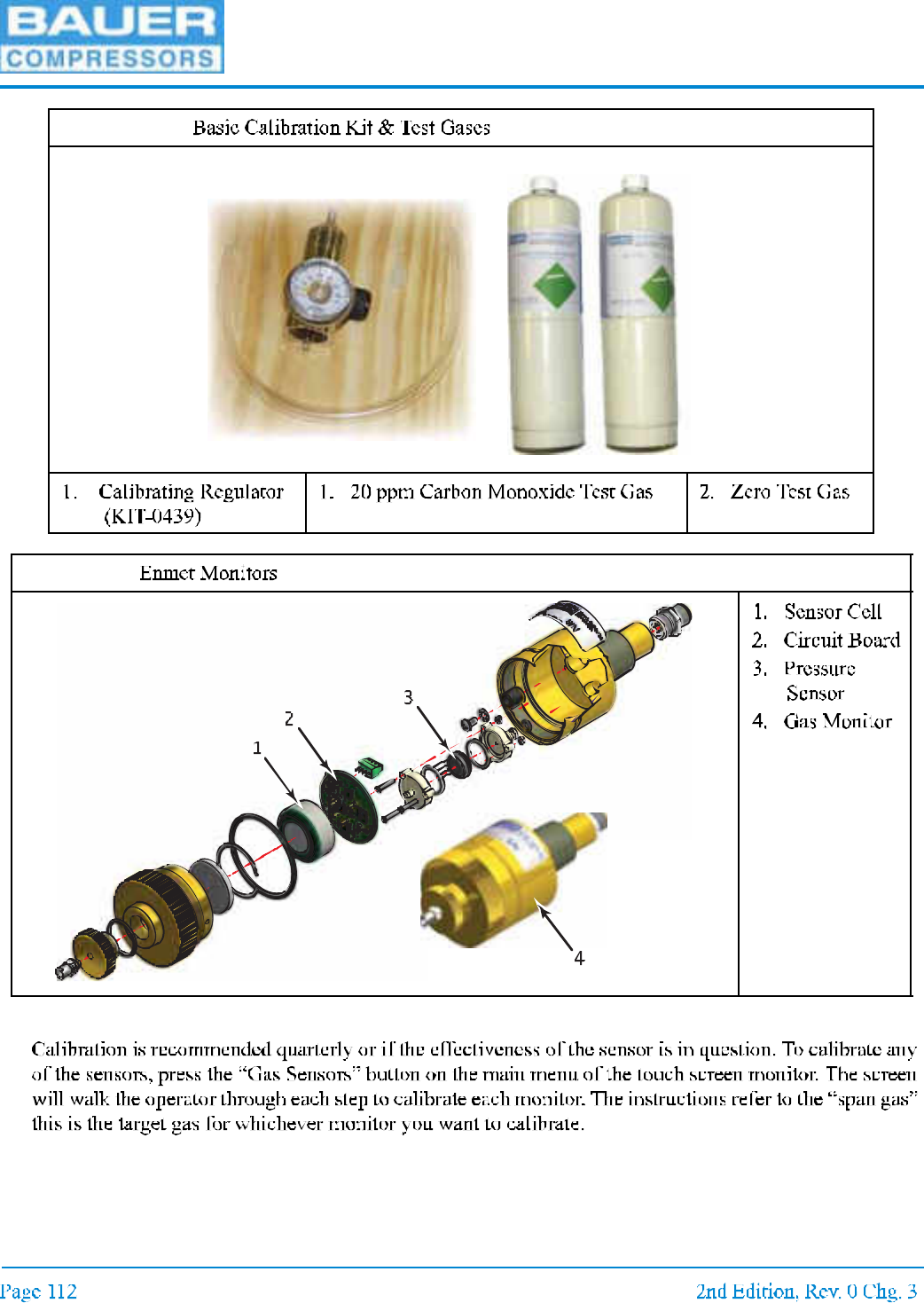
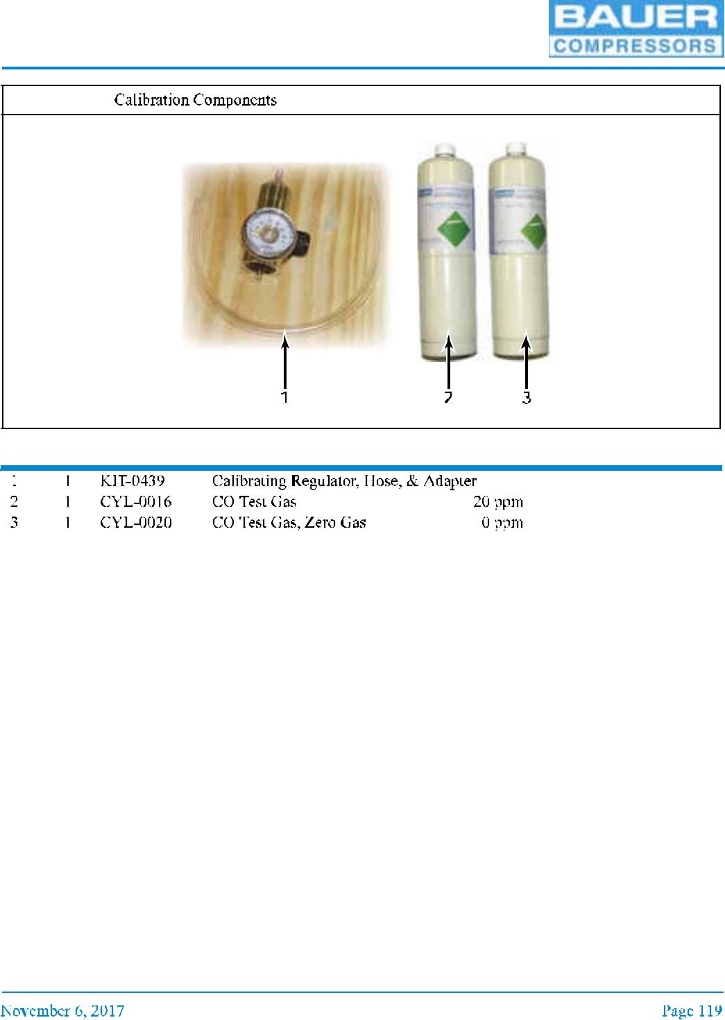
8.3 Calibration
Figure 8-2
Figure 8-3
MNL-0021
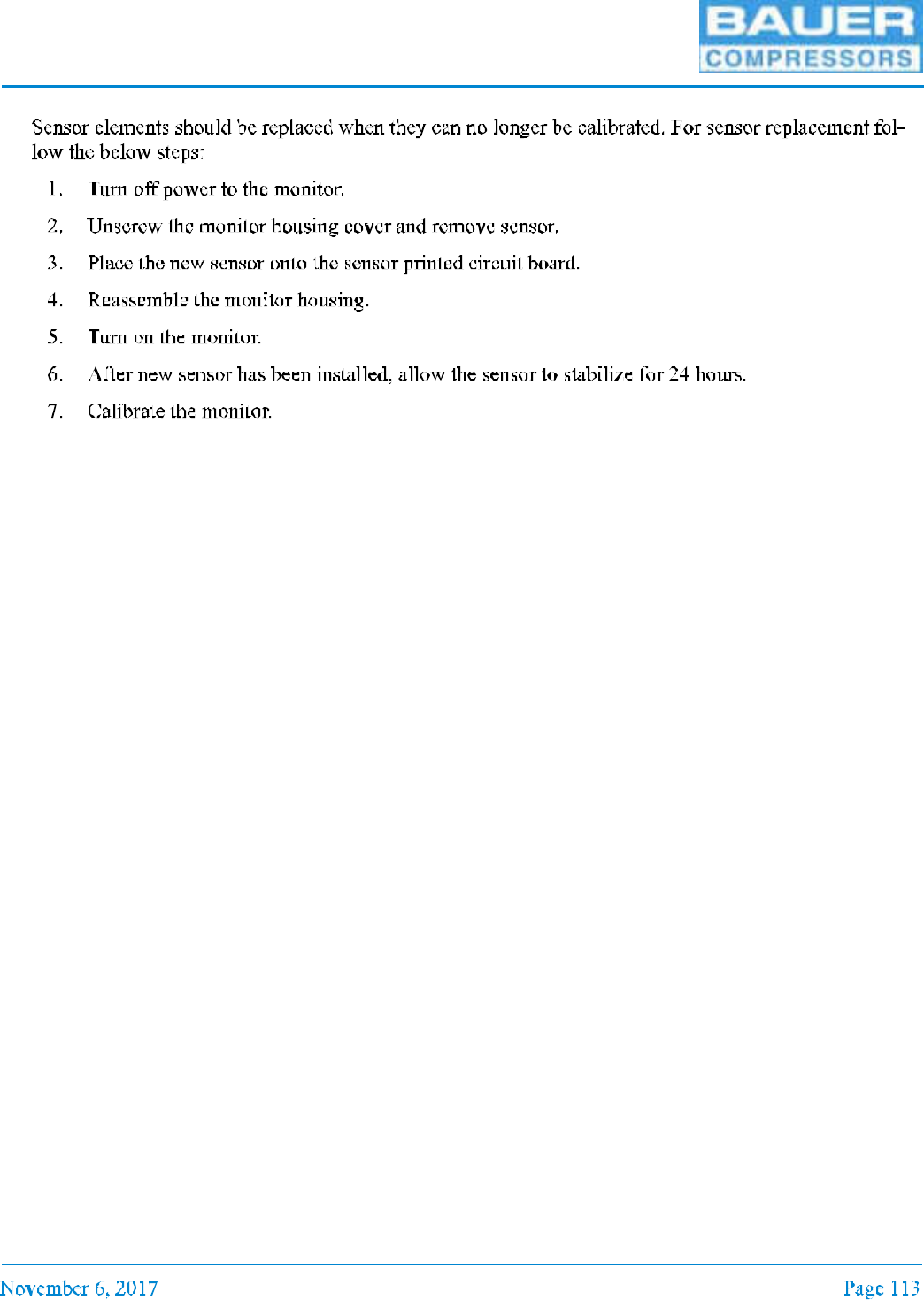
8.4 Sensor Replacement

UNICUS 4i
8.5 Replacement Parts
Item Qty Part No. Description Notes
Figure 8-4
1 2
3
4
5
9
8
6
10
7
UNICUS 4i
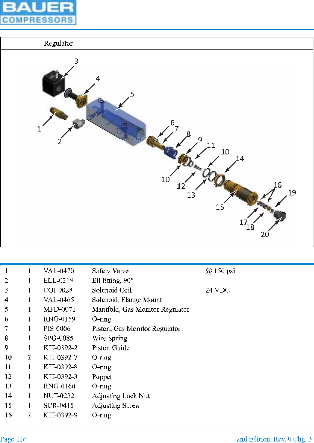
Item Qty Part No. Description Notes
Figure 8-5

MNL-0021
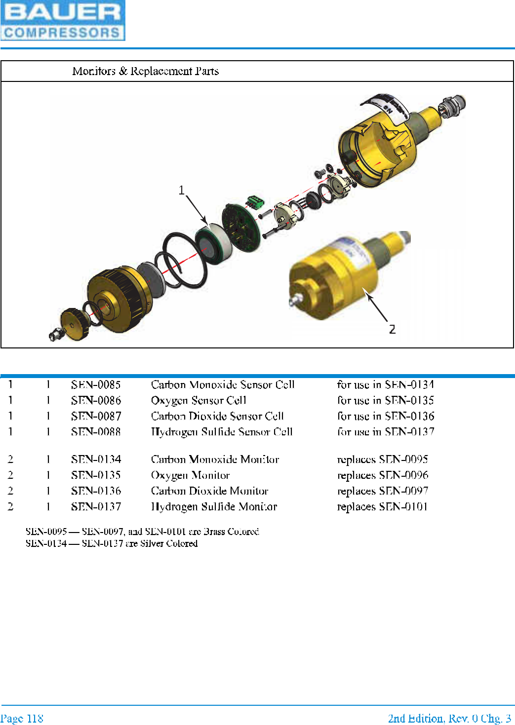
Figure 8-5 (cont.)
Item Qty Part No. Description Notes
UNICUS 4i
Item Qty Part No. Description Notes
*
*
*
*
*
Figure 8-6
MNL-0021
Item Qty Part No. Description Notes
Figure 8-7