Bauer Compressors B-RFID RF ID Reader in Air Fill Station User Manual Part 4
Bauer Compressors, Inc RF ID Reader in Air Fill Station Users Manual Part 4
Contents
- 1. Users Manual Part 1
- 2. Users Manual Part 2
- 3. Users Manual Part 3
- 4. Users Manual Part 4
Users Manual Part 4
UNICUS 4i
CHAPTER 9: CFS III MAINTENANCE
9.1 Description
9.2 Fill Station Air Flow
9.3 Maintenance
9.3.1 General Maintenance
WARNING
MNL-0021
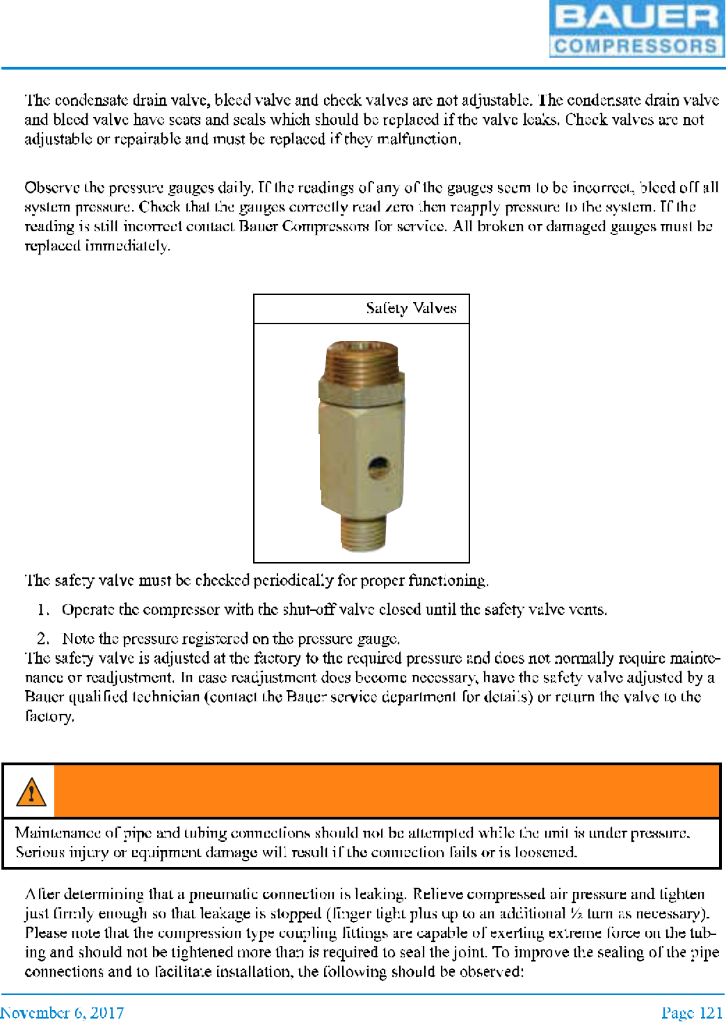
9.3.2 Nonadjustable Valves
9.3.3 Pressure Gauges
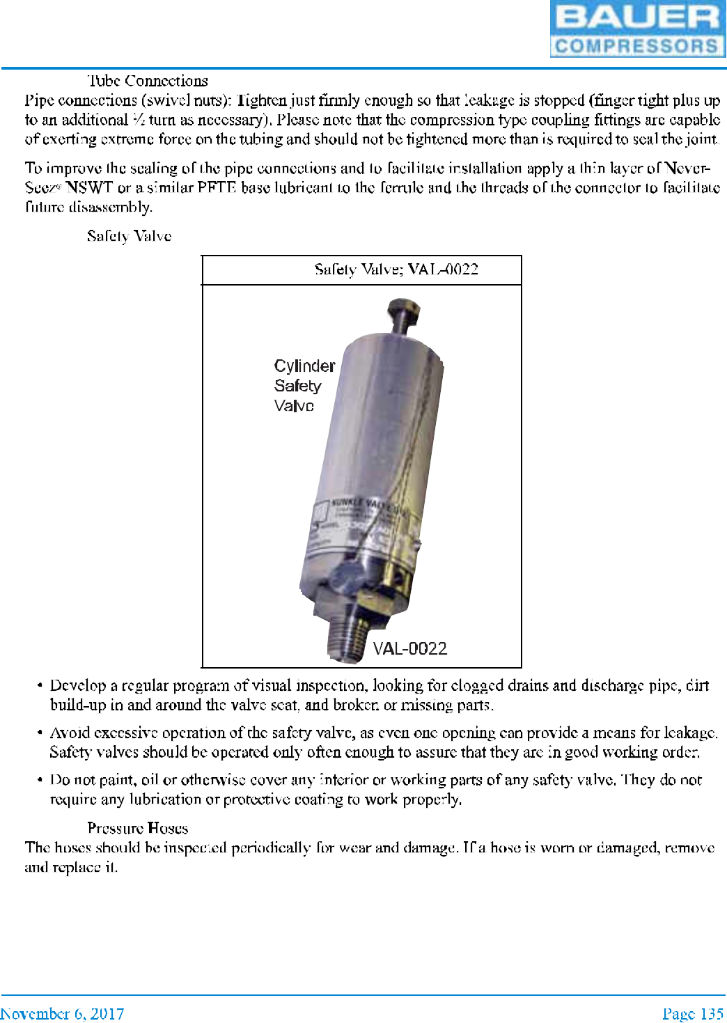
9.3.4 Safety Valves
9.3.5 Pneumatic Connections
Figure 9-1
WARNING
UNICUS 4i
9.3.6 Bearings for Bottle Door Pivot
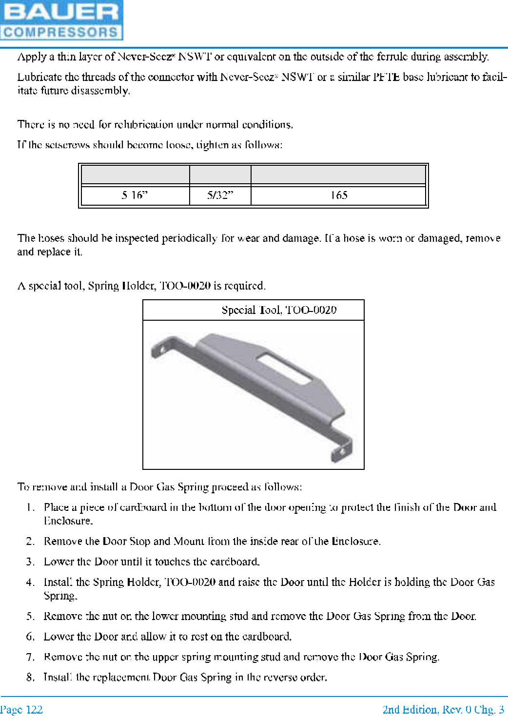
9.3.7 Pressure Hoses
9.3.8 Door Gas Spring
Setscrew diameter Hex size Recommended torque (inch lbs)
Figure 9-2
MNL-0021
9.4 Replacement Parts List
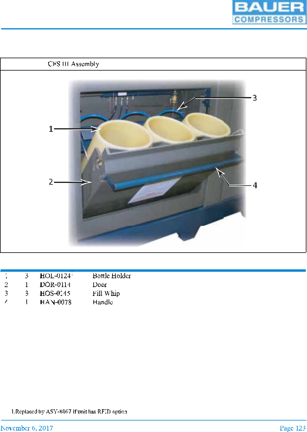
9.4.1 CFS III Assemblies
Item Qty Part No. Description Notes
Figure 9-3
UNICUS 4i
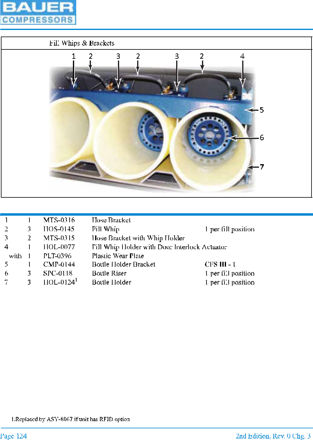
Item Qty Part No. Description Notes
Figure 9-4
MNL-0021
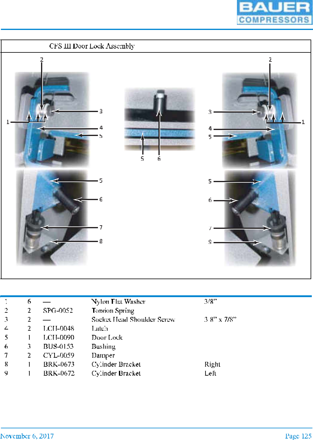
Item Qty Part No. Description Notes
Figure 9-5
UNICUS 4i
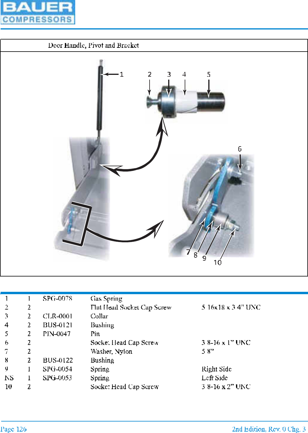
Item Qty Part No. Description Notes
Figure 9-6

MNL-0021
Item Qty Part No. Description Notes
Figure 9-7
UNICUS 4i
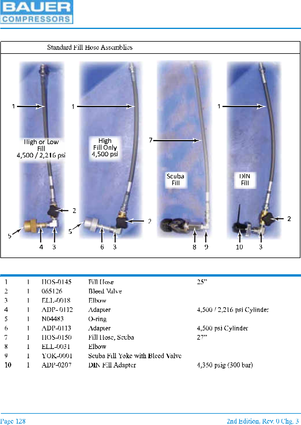
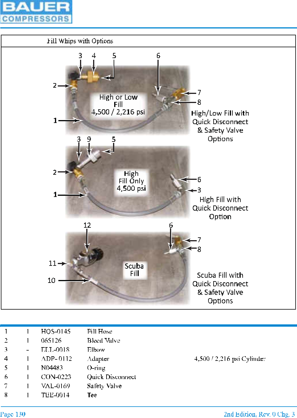
9.5 Fill Hose Assemblies
Item Qty Part No. Description Notes
scuba fill only
Figure 9-8
1 2
3
4
5
9
8
6
10
7
UNICUS 4i
Item Qty Part No. Description Notes
Figure 9-9
MNL-0021
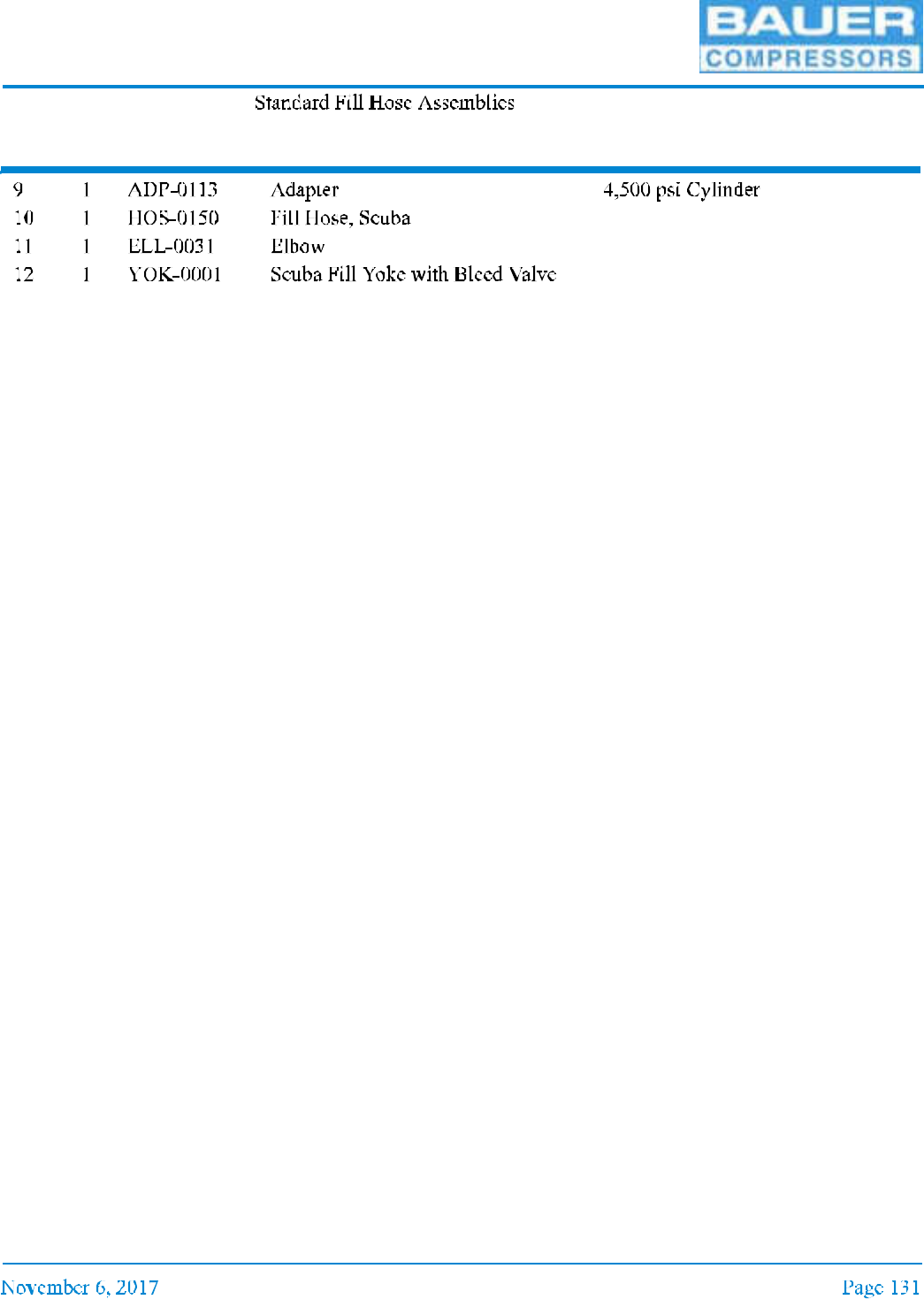
Figure 9-9 (cont.)
Item Qty Part No. Description Notes
UNICUS 4i
CHAPTER 10: UNICUS III HP AIR STORAGE
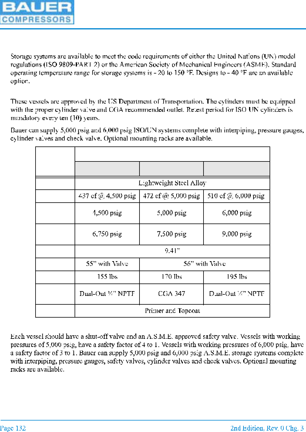
10.1 Bottle Specifications
10.1.1 ISO/UN; ISO 9809-PART2 / United Nations
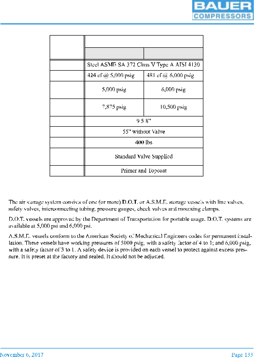
10.1.2 ASME; American Society of Mechanical Engineers
Vessel
ISO / UN
4,500 psig 5,000 psig 6,000 psig
Material
Volume
Working
Pressure
Test
Pressure
Diameter
Height
Weight
Cylinder
Valve
Finish
MNL-0021
10.2 Description and Maintenance
10.2.1 Description
Vessel
ASME
5,250 psig 6,600 psig
Material
Volume
Working
Pressure
Test
Pressure
Diameter
Height
Weight
Cylinder
Valve
Finish

UNICUS 4i
10.2.2 Maintenance
10.2.2.1
10.2.2.2
Figure 10-1
MNL-0021
10.2.2.3
10.2.2.4
10.2.2.5
Figure 10-2
UNICUS 4i
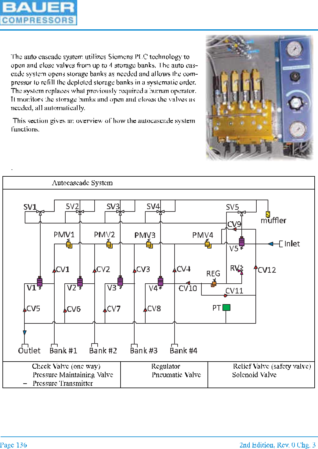
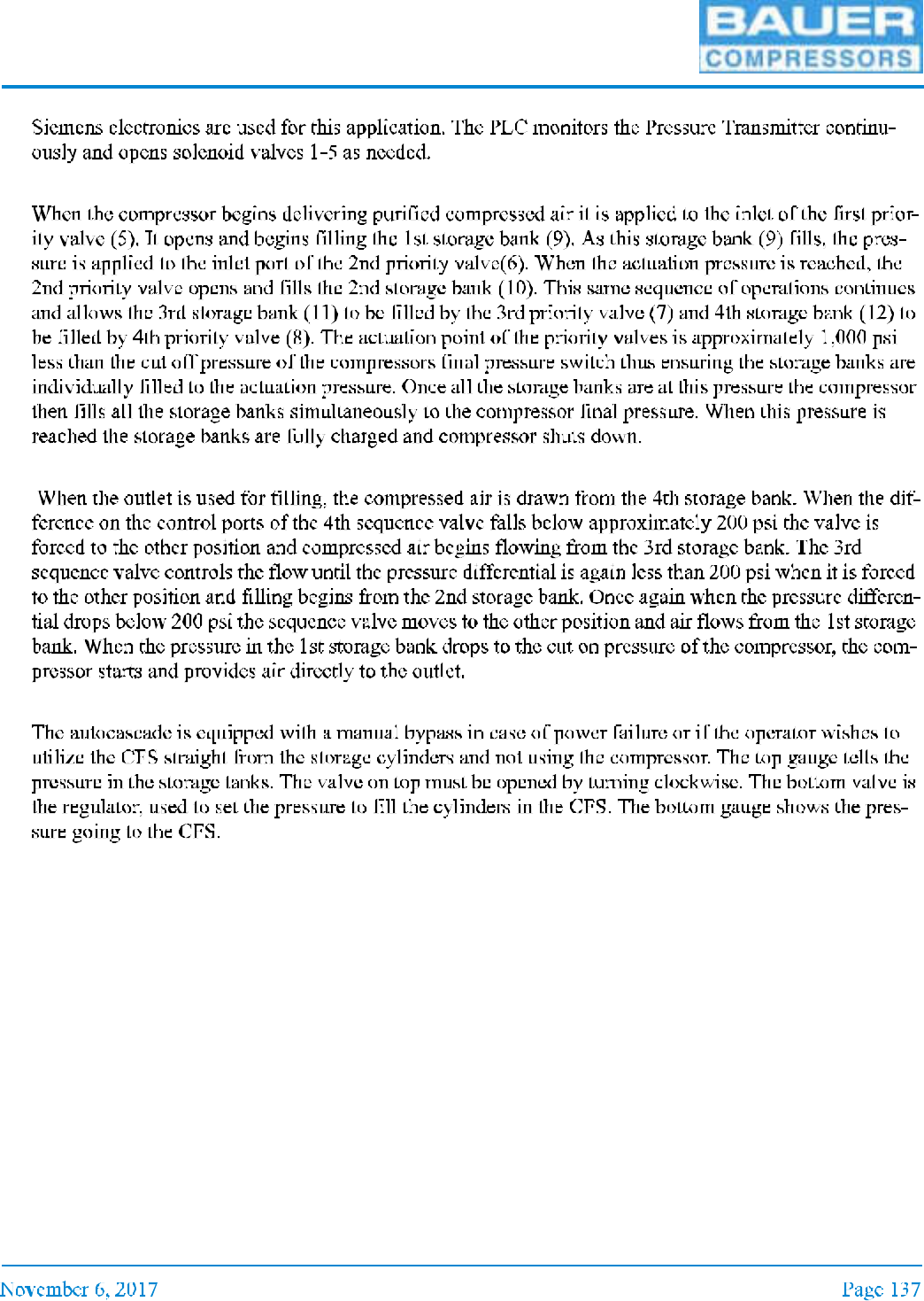
10.3 Autocascade System
10.3.1 General
Figure 10-3
CV
PMV
PT
REG
V
RV
SV
MNL-0021
10.3.2 Electrical
10.3.3 Filling the Storage Banks
10.3.4 Filling Bottles from the Storage Banks
10.3.5 Manual Bypass
UNICUS 4i
CHAPTER 11:APPENDIX
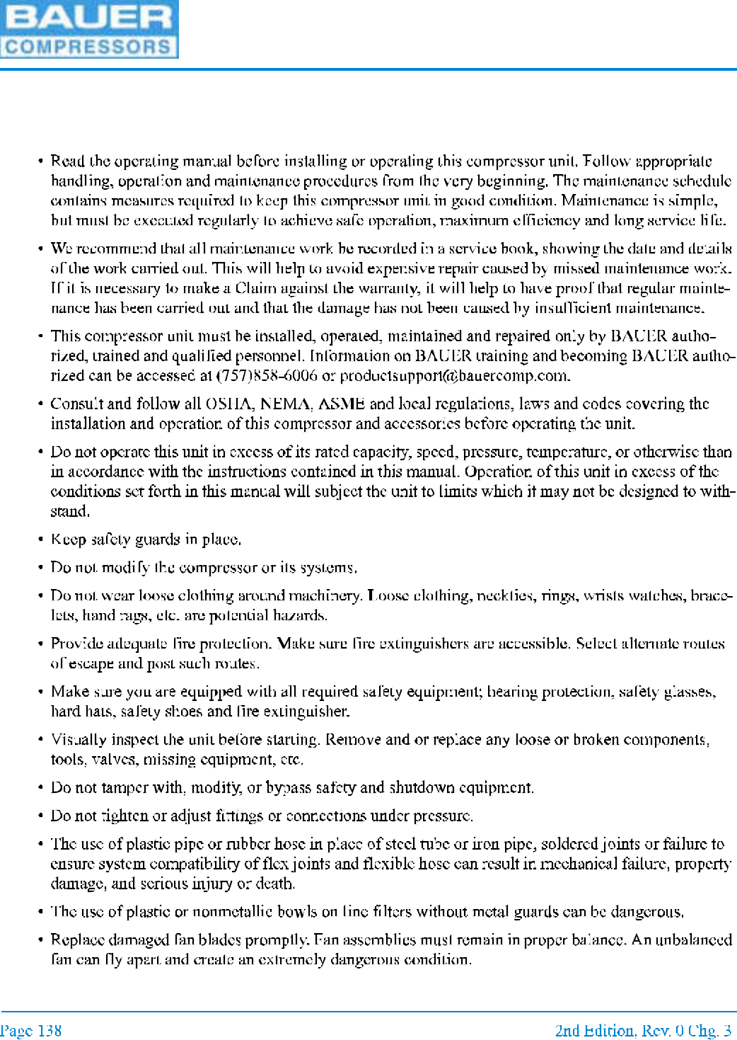
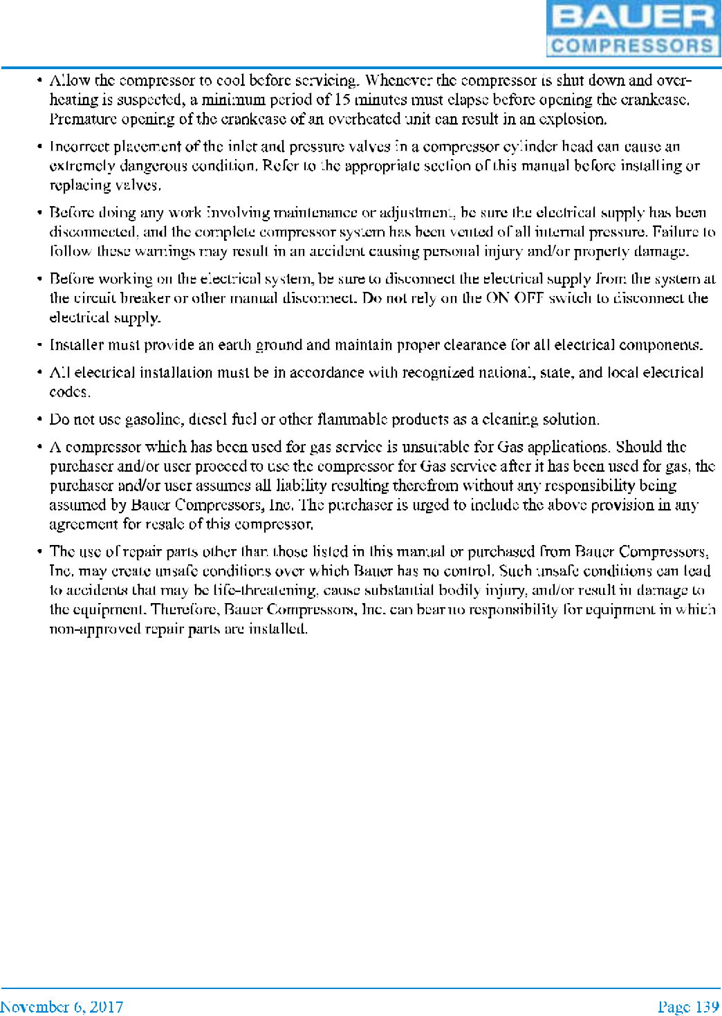
11.1 Safety
11.1.1 General Safety Precautions
MNL-0021
UNICUS 4i
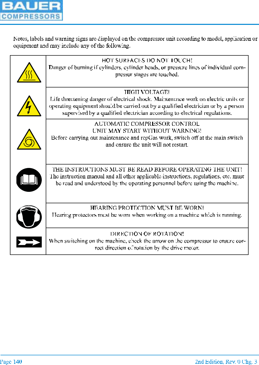
11.1.2 Safety Warning Labels
MNL-0021
11.2 Unpacking, Handling and Installation
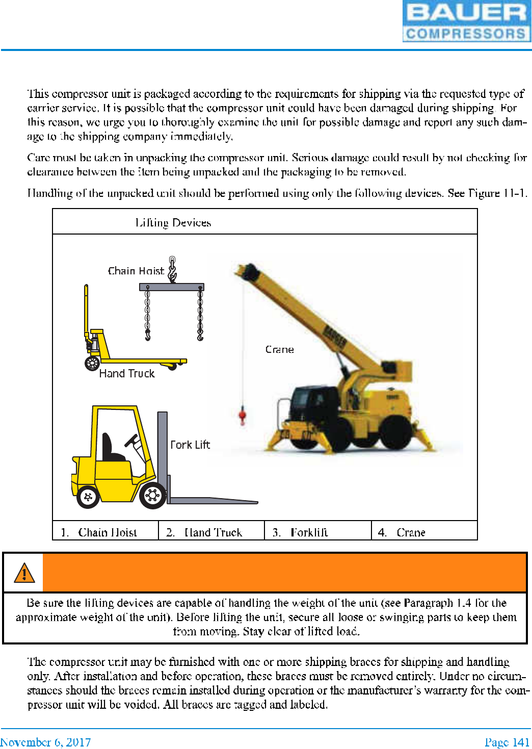
11.2.1 Unpacking and Handling
Figure 11-1
WARNING
UNICUS 4i
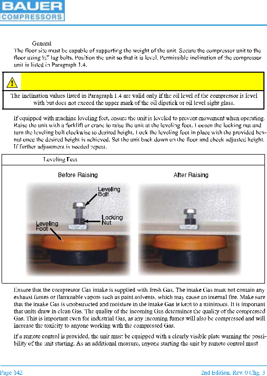
11.2.2 Installation of the Compressor Unit
11.2.2.1
CAUTION
Figure 11-2
MNL-0021
11.2.2.2
11.2.2.2.1
11.2.2.2.2
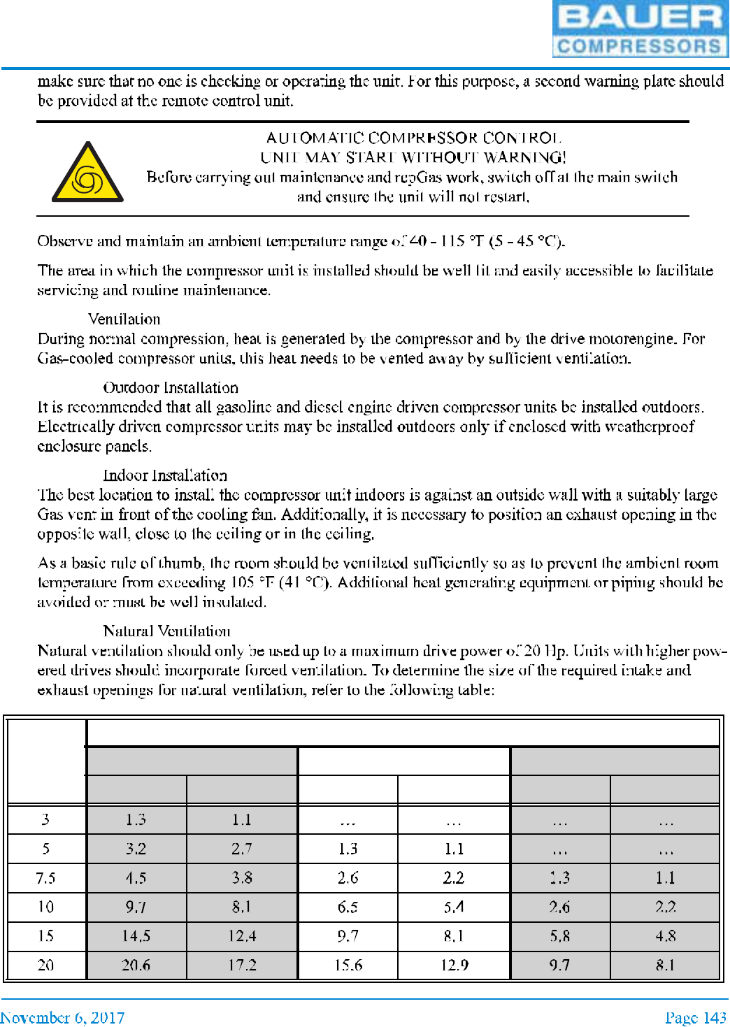
11.2.2.2.3
Drive
Hp
Intake and Exhaust Openings Dependent on Room Volume (V) and Height (h)
V = 1750 ft³ h = 6.5 ft V = 3500 ft³ h = 10 ft V = 7000 ft³ h = 13 ft
Intake (ft²) Exhaust (ft²) Intake (ft²) Exhaust (ft²) Intake (ft²) Exhaust (ft²)

UNICUS 4i
11.2.2.2.4
11.2.3 Intake Gas
11.2.3.1
Drive
Hp
Intake & Exhaust Openings Dependent on Room Volume (V) and Height (h)
a
a. The intake sizes given in the above table are for a cooling Gas velocity of 1000 ft.min. Bauer re commends that the cooling Gas velocity be in the range of
600 ft.min. to 2000 ft.min.
V = 1750 ft³ h = 8 ft V = 3500 ft³ h = 10 ft V = 7000 ft³ h = 13 ft
Intake
(ft²)
Exhaust
cfm
Intake
(ft²)
Exhaust
cfm
Intake
(ft²)
Exhaust
cfm
MNL-0021
11.2.3.2
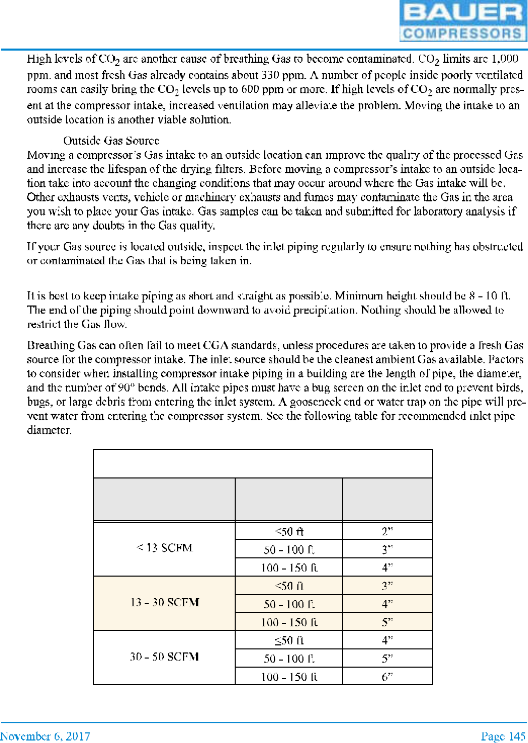
11.2.4 Compressor Intake Piping
Guideline for Intake Piping with Max. Four 90° bends
Inlet Capacity Distance Pipe
Diameter
a
a. Add 1” of pipe diameter if the number of 90° bends exceeds four

UNICUS 4i
11.2.5 Installation Procedures
11.2.6 Electrical Installation
11.2.6.1
11.2.6.2
Figure 11-3

MNL-0021
Figure 11-4
1 PHASE
Motor
Hp
Full Load Amps Fuse Amps
a
a. Dual element time delay fuse Amps.
Minimum Wire Size
b
b. Normal Copper wire with THW, TH WN, o r XHHW insulation.
120 V 208 V 230 V 120 V 208 V 230 V 120 V 208 V 230 V
UNICUS 4i
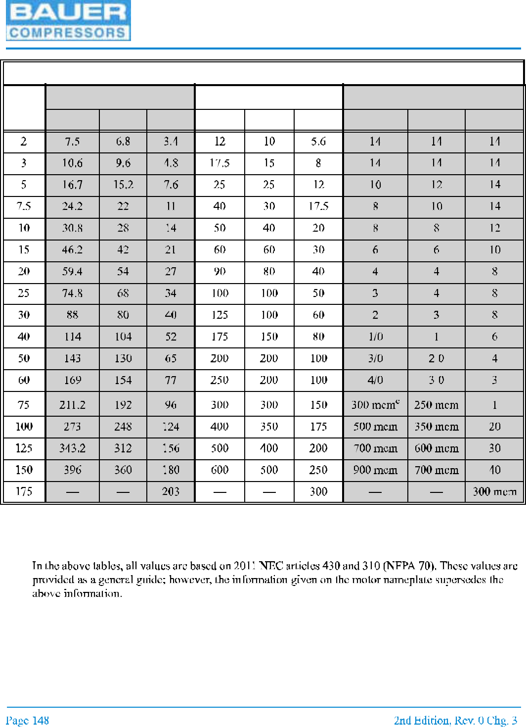
3 PHASE
Motor
Hp
Full Load Amps Fuse Amps
a
a. Dual element time delay fuse Amps.
Minimum Wire Size
b
b. Normal Copper wire with THW, TH WN or XHHW insulation.
208 V 230 V 460V 208 V 230 V 460V 208 V 230 V 460V
c. mcm = 1,000 circular mils
MNL-0021
11.2.7 Pneumatic Leaks
11.3 Long Term Storage
11.3.1 General
11.3.2 Preparations
11.3.2.1
11.3.3 Preserving the Compressor
WARNING
UNICUS 4i
11.3.4 Preventive Maintenance During Storage
11.3.5 Lubrication Oils for Preservation
11.3.6 Reactivating the Compressor Unit
MNL-0021
11.4 Reproducible Forms
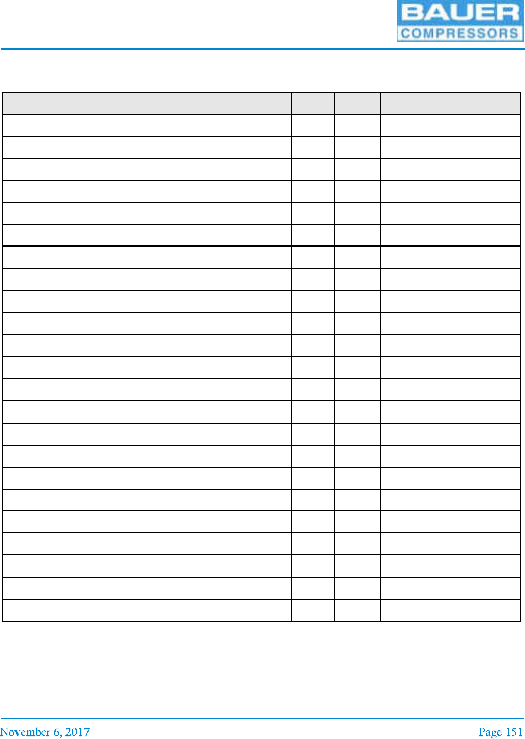
11.4.1 Scheduled Maintenance Form
Daily Para. Date Signature
UNICUS 4i
Weekly or as required. Para. Date Signature
500 Operating Hours. Para. Date Signature
1,000 Operating Hours. Para. Date Signature
2,000 Operating Hours. Para. Date Signature
MNL-0021
3,000 Operating Hours. Para. Date Signature
Annually. Para. Date Signature
Biennially. (Every two years) Para. Date Signature
UNICUS 4i
11.4.2 Cartridge Operating Hours
Date Operating
hours
Ambient temp. + 18°F
during compression
Correction
factor
Adjusted cartridge hours
Today Total

MNL-0021
11.4.3 Record of Operating Hours
Date Minutes Total Date Minutes Total
UNICUS 4i
11.5 Reference Data
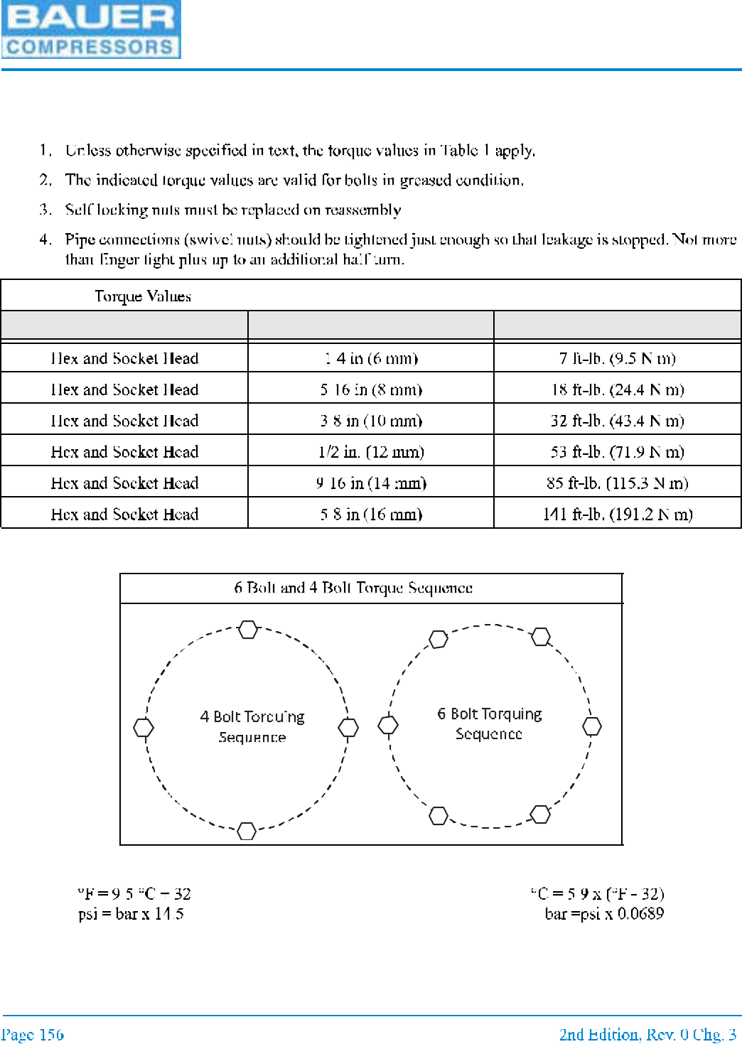
11.5.1 Tightening Torque Values
11.5.2 Torque Sequence Diagrams
11.5.3 Conversion Formulas
Table 11-1:
Bolt or Screw Size Max. Torque
Figure 11-5
12
3
4
12
3
4
5
6

MNL-0021
11.5.4 Approved Lubricants Chart
11.5.5 Glossary of Abbreviations and Acronyms
A C
A C D
A S M E
C W
C C w
C G A
D I N
D o T
E 1
E 3
H c
I A W
M S
N E C
N E M A
N F P A
O S H A
O D p
O E M
P L C
P M V
S c
Table 11-2:
Usage Lubricants
UNICUS 4i
11.6 Additional Documents
11.6.1 Diagrams and Drawings
11.6.2 Other Documents
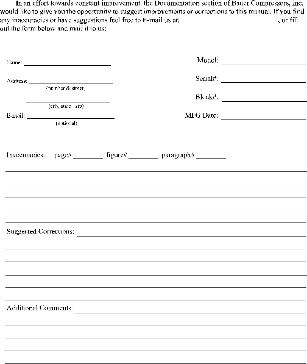
CORRECTIONS & COMMENTS
documentation@bauercomp.com
Submitters Contact Information: Unit Information: