Boston Scientific Neuromodulation PSC5210W Precision SCS System Remote Control User Manual II Physicans Implant
Boston Scientific Neuromodulation Corporation Precision SCS System Remote Control II Physicans Implant
Contents
Physician Implant Manual
Physician Implant Manual
CAUTION:
Federal law restricts this device to sale, distribution and use by or on
the order of a physician.
MP9055182 Rev A
DRAFT

Physician Implant Manual
ii ©2004 by Advanced Bionics Corporation. All Rights Reserved.
Copyright
©2004 by Advanced Bionics Corporation. All Rights Reserved. Any
copying, reproduction or translation of all or part of the contents of
this document without the express written permission of Advanced
Bionics Corporation is strictly forbidden by the provisions of the law
of March 11th, 1957.
Guarantees
Advanced Bionics Corporation reserves the right to modify, without
prior notice, information relating to its products in order to improve
their reliability or operating capacity.
Registered Trademarks
BionicNavigator™ and Precision™ are registered trademarks of
Advanced Bionics Corporation. Velcro® is a registered mark of Velcro
Industries, Manchester, New Hampshire. Other brands and their prod-
ucts are trademarks or registered trademarks of their respective hold-
ers and should be noted as such.

Table of Contents
iii
Table of Contents
Introduction ............................................... 1
Manual Overview ........................................................... 1
Device Description .......................................................... 1
Features ........................................................................1
Indications for Use ...........................................................2
Precision System Clinical Summary .....................................2
Efficacy Evaluation .................................................... 2
Safety Evaluation .......................................................5
............................................................................. 6
Clinical Experience-Safety ...........................................6
References ............................................................... 7
Contraindications ............................................................8
Safety Information ..................................... 9
Warnings ......................................................................9
Precautions .................................................................. 10
Adverse Effects ............................................................. 11
Instructions for the Physician .............................................13
Sterilization ..................................................................13
Handling .....................................................................15
Storage .......................................................................15
Package Contents .................................... 16
Patient Identification ................................ 17
Guidelines for Permanent Implantation .... 18
Percutaneous Lead/Extension Removal ..............................18
Option A. Temporary Lead Removal ...........................18
Option B. Extension Removal .....................................18

iv
Physician Implant Manual
IPG Implantation ........................................................... 20
Tool Assembly .............................................................. 21
Tunneling The Lead ........................................................ 21
Connecting To the IPG ...................................................25
Dual Lead Connection .............................................. 25
Single Lead Connection ............................................25
IPG Explant or Replacement ..................... 28
Rechargable Implant System .................... 29
IPG Battery Status .......................................................... 29
Charging Steps ............................................................ 30
Patient Remote Control ............................. 34
Basic Operation ........................................................... 34
Stimulation On/Off ................................................. 35
Stimulation Amplitude ...............................................35
Coverage Area Selection ..........................................36
Program Selection ................................................... 36
Modifying and Saving Programs ................................36
Options ................................................................. 38
Device Linking ..............................................................39
Clinician Options ..........................................................42
To Clear Link .......................................................... 43
For CP Mode ......................................................... 44
For Impedances ...................................................... 45
Programmer Communication ...........................................47
Specifications and Technical Data ............. 48
.................................................................................48
Materials .....................................................................48

Table of Contents
v
Maximum Current Amplitude per Electrode
versus Impedance .................................... 49
Registration Information .......................... 50
Registering the Implant ...................................................50
Technical Service ...................................... 51
Limited Warranty ..................................... 52

vi
Physician Implant Manual

Introduction
1
Introduction
Manual Overview
This manual provides basic information for the implantation and
operation of the Precision™ Implantable Pulse Generator (IPG),
Model SC-1110. This information includes an overview of accesso-
ries for programming and powering the IPG, clinical and surgical con-
siderations, storage and handling requirements, and relevant
precautions concerning an implanted neurostimulator. Additional
information on system components and operation can be found in the
BionicNavigator™ Software Guide.
Device Description
The Advanced Bionics® Precision implantable pulse generator system
is intended to treat chronic pain by electrically stimulating the spinal
cord. The multi-channel, multi-electrode device capability provides
flexibility in conjunction with ease of programming. A rechargeable
battery increases IPG longevity and output capability while reducing
size and device replacement surgeries. The implant is controlled by a
handheld Remote Control, and can be engaged by a clinician com-
puter using proprietary BionicNavigator software. Periodically, the
implant battery requires replenishing with an RF charging device pro-
vided in the Patient Take Home Kit SC-6000-02.
Features
• Stimulation electrode field navigation
• Sixteen independent current-controlled electrodes
• Four programmable stimulation areas per program; four
possible programs
• Long-life operation
• High-range parameter capability
•Small size
• Two-foot programming range

2
Physician Implant Manual
Indications for Use
The Advanced Bionics PRECISION™ Spinal Cord Stimulator System
(PRECISION™ System) is indicated as an aid in the management of
chronic intractable pain of the trunk and/or limbs, including unilateral
or bilateral pain associated with the following: failed back surgery
syndrome, intractable low back pain and leg pain.
Precision System Clinical Summary
Determination of the safety and effectiveness of the PRECISION Sys-
tem was based on available published clinical studies for similar
implanted spinal cord stimulation systems. The PRECISION System
is similar to the SCS systems reported in published literature in
intended use, target patient population, technology, device design, and
output characteristics. Therefore, the clinical data from the published
literature described below represents evidence supporting the safety
and effectiveness of the PRECISION System for the treatment
chronic intractable pain of the trunk and/or limbs, including unilateral
or bilateral pain associated with the following: failed back surgery
syndrome, intractable low back and leg pain.
Efficacy Evaluation
Three (3) clinical literature studies were used to support the effective-
ness of the PRECISION System (Ohnmeiss et al. 1996, Villavincen-
cio et al. 2000, Hassenbach SJ et al. 1995). The studies included a
total of 116 patients that were implanted with an SCS system. A total
of approximately 3166 device months of experience was depicted
from the retrospective clinical evaluation. All three studies examined
the effectiveness of SCS on patients with chronic pain of the trunk
and/or limbs including unilateral or bilateral pain associated with the
following: failed back surgery syndrome or intractable low back and
leg pain. In all studies, a totally implantable spinal cord stimulator
was used in association with a percutaneous and/or surgical lead.
These studies provide the same diagnostic or therapeutic intervention

Introduction
3
for the same disease/conditions and patient population as the PRECI-
SION System.
The prospective study by Ohnmeiss et al. 1996, examined the long-
term effectiveness of SCS in patients with intractable leg pain. Forty
patients were implanted with SCS systems and evaluated at 6 weeks,
12 months, and 24 months follow-up. Outcome measures included the
VAS, pain drawings, medication use, SIP (Sickness Impact Profile),
isometric lower extremity testing, and patient questionnaires. An
intent-to-treat analysis was performed. After patients had SCS for 24
months, leg pain, pain when walking, standing pain, pain’s effect on
overall lifestyle, and the total analog scale scores were significantly
improved from baseline. In this study, 25% of the implanted patients
had greater than 50% improvement in pain rating.
In addition, 3 patients from this study had their stimulators reposi-
tioned due to pain at the original location. Three patients had reopera-
tions to adjust lead position; 1 patient required 2 reoperations, 1
patient had the device removed due to infection and later to have a
new device implanted. A diabetic patient had skin problems which
required device removal; a new device was later implanted. Two
patients had the device removed due to unsatisfactory pain relief.
The prospective study performed by Villavicencio et al. 2000
included 41 patients with pain of various etiologies. The majority of
the patients, 24 (59%), had Failed Back Surgery Syndrome (FBSS), 7
(17%) had Complex Regional Pain Syndrome (CRPS I and II), 4
(10%) had neuropathic pain syndrome, and 6 (15%) were diagnosed
as stroke or other. Patients underwent an initial trial period for SCS
with temporary leads. If the trial resulted in greater than 50% reduc-
tion in the patient’s pain, as measured by the VAS, the patient was
implanted with a SCS system. In this study, 27/41 patients, 66%, had
permanent implants. All patients were examined after 6 weeks. Pain
measurements were assessed at 3-6 month intervals for the first year
and annually thereafter. The median long-term follow-up was 34
months. A total of 24/27 (89%), reported greater than 50% reduction

4
Physician Implant Manual
in pain. Since the majority of the patients were treated for FBSS, this
article supports the use of SCS for the treatment of FBSS.
In this study, one patient required a revision because of electrode frac-
ture. One patient required removal of the system due to local infec-
tion. One patient required replacement of the IPG due to mechanical
failure. Overall, 16 of 27 (59%) patients required a total of 36 reposi-
tioning procedures.
A retrospective analysis performed by Hassenbusch SJ et al. 1995
included patients with chronic lower body pain, predominately neuro-
pathic pain and pain either midline lower back and/or unilateral or
bilateral leg pain treated over a 5 year period. The study was a com-
parison of SCS to spinal infusion of opiods. For patients with radicu-
lar pain involving one leg with or without unilateral buttock pain, a
trial of SCS was recommended first. For patients with midline back
pain and /or bilateral leg pain, a trial of long-term spinal infusion was
recommended first. If the patients failed screening with either of these
modalities, the other was then tested. If the treatment reduced the pain
by 50%, the systems were internalized. A retrospective analysis of
patients with unilateral leg and/or buttock pain treated initially with
SCS and bilateral leg or mainly low back pain treated initially with
spinal infusions of opioids was then done.
In this study, 42 patients were screened; 26 (62%) patients received
spinal stimulation; 16 (38%) received opioids via a spinal infusion
pump. Five patients did not receive adequate pain relief with SCS; 3
(7%) of these patients underwent trial spinal infusions and had effec-
tive pain relief. There were 4 (10%) patients who underwent a trial of
spinal infusion of opioid but did not receive adequate pain relief;
these patients were not tested with SCS. Pain severity was rated using
a verbal digital pain scale: “On a scale of 0 to 10 where 0 is no pain
and 10 is the worst pain you could ever imagine, what is your pain
now?” 16/26 patients (62%) had greater than 50% pain relief with
SCS. In this study, 2/16 (13%) had greater than 50% pain relief with

Introduction
5
opioids. Mean follow-up was 2.1 + 0.3 years. This analysis supports
the use of SCS for intractable low back and leg pain.
In this study, 7 (17%) patients suffered complications after implanta-
tion of the device; 5 (12%) patients required repositioning of catheter
type electrodes and 2 patients required revision of the stimulator gen-
erator.
Safety Evaluation
Eleven studies were identified based on the detailed inclusion/exclu-
sion criteria to demonstrate the safety of the PRECISION System.
The studies included a total of 1056 patients that were trialed with
SCS systems and 880 patients that received implants. The table below
depicts the number of patients, the number of events, and the percent-
age of occurrences of each event compared to the total number of
patients. It should be noted that citations cover both IPG and RF Sys-
tems. The clinical experience reported in the literature on RF systems
is relevant to determining the safety of totally implantable IPG sys-
tems.
Table 1: Summary of Risks Identified in the Retrospective
Clinical Studies
Risks
# Patients
With
Adverse
Event
Intent-to-
Treat Basis
N = 1056
Implanted
Patient
Basis
N = 880
Lead Migration 175 16.6% 19.9%
Infection 39 3.7% 4.4%
Epidural Hemorrhage 0 0% 0%
Seroma 0 0% 0%
Hematoma 1 0.1% 0.1%
Paralysis 0 0% 0%
CSF Leak 5 0.5% 0.6%

6
Physician Implant Manual
Clinical Experience-Safety
Clinical data has been collected during a clinical study of the PRECI-
SION™ System. As of January 15, 2004, 35 subjects were enrolled in
the study at multiple sites and 26 subjects had a successful trial stimu-
lation period and were implanted with the PRECISION™ System.
The follow-up period for the 26 implanted patients ranged from 2
weeks to 6 months. The following major adverse events were
reported.
Table 2: Clinical Experience Safety
Over/Under Stimula-
tion, Ineffective Pain
Control
46 4.4% 5.2%
Intermittent Stimula-
tion
00%0%
Pain Over Implant 16 1.5% 1.8%
Allergic Reaction 6 0.6% 0.7%
Skin Erosion 0 0% 0%
Lead Breakage 35 3.3% 4.0%
Hardware Malfunction 22 2.1% 2.5%
Loose Connection 0 0% 0%
Battery Failure 2 0.2% 0.2%
Other 45 4.3% 5.1%
Type Number of Patients Resolution
Lead Migration 1 Lead repositioning
and subsequent
replacement
Output malfunction 1 Device replaced
Introduction
7
Other minor adverse events reported by at least one patient included:
receiver malfunction, skin irritation, unpleasant stimulation, CSF
leak, infection at implant site, lead migration, and OR cable malfunc-
tion. Two of the subjects reported multiple events.
References
Burchiel, K.J., V.C. Anderson, F.D. Brown, R.G. Fessler, W.A.
Friedman, S. Pelofsky, R.L. Weiner, J. Oakley,and D. Shatin.
“Prospective, Multicenter Study of Spinal Cord Stimulation for
Relief of Chronic Back and Extremity Pain.” Spine, 21:2786-
2793, 1996.
Hassenbusch, S.J., M. Stanton-Hicks, E.C. Covington. “Spinal cord
stimulation verses spinal infusion for low back and leg pain”.
Acta Neurochirgica, 64:109-115, 1995.
Kemler, M.A., G.A.M. Barendse, M. Van Kleef, H.C.W. De Vet,
C.P.M. Rijks, C.A. Furnee and F.A.J.M. Van den Wilderberg.
“Spinal Cord Stimulation in Patients with Chronic Reflex
Sympathetic Dystrophy.” New England J of Medicine, 343:
618-24, 2000.
Kim S. H., R.R. Tasker, and M.Y. Oh. “Spinal Cord Stimulation for
Nonspecific Limb Pain versus Neuropathic Pain and
Spontaneous versus Evoked Pain.” Neurosurgery, 48(5): 1056-
1064, 2001.
Kumar, K., C. Toth, R. Nath, and P. Lang. “Epidural Spinal Cord
Stimulation for Treatment of Chronic Pain-Some Predictors of
Success. A 15 year experience.” Surg Neurol, 50: 110-120,
1998.
Infection 1 Infection treated
Pain 1 Lead explanted

8
Physician Implant Manual
Lang, P. “The Treatment of Chronic Pain by Epidural Spinal Cord
Stimulation.” AXON, 18(4): 71-73, 1997.
Ohnmeiss, D., R. Rashbaum, M. Bogdanffy. Prospective Outcome
Evaluation of Spinal Cord Stimulation in Patients With
Intractable Leg Pain. Spine, 21:1344-1351, 1996.
Rainov, N.G., V. Heidecke, and W. Burkert. “Short Test-Period Spinal
Cord Stimulation for Failed Back Surgery Syndrome.” Minim
Invasive Neurosurg, 39(2):41-44, 1996.
Segal, R., B. Stacey, T. Rudy, S. Basser, J. Markham. “Spinal Cord
Stimulation Revisited.” Neurological Research, 20:391-396,
1998.
Spieglemann, R. and W.A. Friedman. “Spinal Cord Stimulation: A
Contemporary Series.” Neurosurg 28:65-71, 1991.
Villavicencio, A.T., J.C. Leveque, L. Rubin, K. Bulsara, and J.P.
Gorecki. “Laminectomy versus percutaneous electrode
placement for spinal cord stimulation.” Neurosurgery, 46:399-
406, 2000.
Contraindications
Patients contraindicated for permanent SCS therapy are those who:
• are unable to operate the SCS system
• have failed trial stimulation by failing to receive effec-
tive pain relief
• are poor surgical risks
• are pregnant

Safety Information
9
Safety Information
Warnings
Magnetic Resonance Imaging (MRI). Patients implanted with the
Precision SCS system should not be subjected to MRI. MRI exposure
may result in dislodgement of implanted components, heating of the
neurostimulator, damage to the device electronics and/or voltage
induction through the leads and stimulator causing an uncomfortable
or “jolting” sensation.
Pediatric Use. The safety and effectiveness of spinal cord stimula-
tion has not been established for pediatric use.
Diathermy. Shortwave, microwave and/or therapeutic ultrasound
diathermy should not be used on SCS patients. The energy generated
by diathermy can be transferred through the stimulator system, caus-
ing tissue damage at the lead site and resulting in severe injury or
death. The IPG, whether it is turned on or off, may be damaged.
Implanted Stimulation Devices. Spinal cord stimulators may
interfere with the operation of implanted sensing stimulators such as
pacemakers or cardioverter defibrillators. The effects of implanted
stimulation devices on neurostimulators is unknown.
Implant Damage. Burns may result if the pulse generator case is
ruptured or pierced and patient tissue is exposed to battery chemicals.
Do not implant the device if the case is damaged.
Postural Changes. Patients should be advised that changes in pos-
ture or abrupt movements may cause decreases, or uncomfortable or
painful increases in the perceived stimulation level. Patients should
be advised to turn down the amplitude or turn off the IPG before mak-
ing posture changes. If unpleasant sensations occur, the IPG should be
turned off immediately.

10
Physician Implant Manual
Electromagnetic Interference. Strong electromagnetic fields can
potentially turn the stimulator off, or cause uncomfortable or jolting
stimulation. Patients should be counseled to avoid or exercise care
around:
• Theft detectors or security screeners such as those used
at entrances/exits of department stores, libraries, and
other public establishments, and/or airport security
screening devices. It is recommended that patients
request assistance to bypass the device. If they must pro-
ceed through the device, the patient should turn off the
stimulator and proceed with caution, ensuring to move
through the center of the screener as quickly as possible.
• Power lines or power generators
• Electric steel furnaces and arc welders
• Large, magnetized stereo speakers
Precautions
Physician training is required.
Medical Devices/Therapies. The following medical therapies or
procedures may turn stimulation off or may cause permanent damage
to the implant, particularly if used in close proximity to the device:
• lithotripsy
• electrocautery: Do not use monopolar cautery.
• external defibrillation
• radiation therapy
• ultrasonic scanning
• high-output ultrasound
If any of the above is required by medical necessity, refer to “Instruc-
tions for the Physician” on page 15. Ultimately, however, the device
may require explantation as a result of damage to the device.

Safety Information
11
Automobiles and Other Equipment. Patients should not operate
automobiles, other motorized vehicles, or potentially dangerous
machinery/equipment with therapeutic stimulation switched on. Stim-
ulation must be turned off first. Sudden stimulation changes, if they
occur, may distract patients from attentive operation of the vehicle or
equipment.
Cell Phones. While we don’t anticipate any interference with cell
phones, the full effects of interaction with cell phones are unknown at
this time.
Post Operative. During the two weeks following surgery, it is
important to use extreme care so that appropriate healing will secure
the implanted components and close the surgical incisions: Do not
exercise or attempt to move heavy objects, and avoid deep bending
and stretching. Temporarily, there may be some pain in the area of the
implant as the incisions heal. If discomfort continues beyond two
weeks, contact your physician. If you notice excessive redness around
the wound areas during this time, contact your physician to check for
infection and administer proper treatment. In rare cases, adverse tis-
sue reaction to implanted materials can occur during this period.
Implant Location. Never attempt to change the orientation or “flip”
the implant. Do not “finger” or play with the implant. If the implant
flips over in your body it cannot be charged. If you know that the
device has turned, or if stimulation cannot be turned on after charging,
contact your physician to arrange an evaluation of the system. In
some cases, the skin over your implant may become very thin over
time. If this occurs, contact your physician.
Lead Location. In some instances a lead can move from its original
location, and stimulation at the intended pain site can be lost. If this
occurs, consult your physician who may able to restore stimulation by
reprogramming the implant in the clinic or repositioning the lead dur-
ing another operation.

12
Physician Implant Manual
Device Failure. Implants can fail at any time due to random compo-
nent failure, loss of battery functionality, or lead breakage. If the
device stops working even after complete charging (up to four hours),
turn off the implant and contact your physician so that the system can
be evaluated.
Storage. Do not expose the Remote Control or Charging System
components to excessively hot or cold conditions. Do not leave the
devices in your car or outdoors for extended periods of time. The sen-
sitive electronics can be damaged by temperature extremes, particu-
larly high heat. If the Remote Control or the Charging System is to be
stored for a period of time, be careful that the storage temperature
does not exceed -20–60 °C (-4–140 °F).
Handling. Handle the system components and accessories with care.
Do not drop them or submerge them in water. Although reliability
testing has been performed to ensure quality manufacturing and per-
formance, dropping the devices on hard surfaces or in water, or other
rough handling, can permanently damage the components. (See “Lim-
ited Warranty” on page 54.)
Component Disposal. Do not dispose of the Remote Control or
Charger in fire. The battery in these devices can explode in fire. Dis-
pose of used batteries in accordance with local regulations. The IPG
should be explanted in the case of cremation, and returned to
Advanced Bionics.
Remote Control, Charging System Cleaning. The components
can be cleaned using alcohol or a mild detergent applied with a cloth
or tissue. Residue from soapy detergents should be removed with a
damp cloth. Do not use abrasive cleansers for cleaning.

Safety Information
13
Adverse Effects
Potential risks are involved with any surgery. The possible risks of
implanting a pulse generator as part of a system to deliver spinal cord
stimulation include:
• Lead migration, resulting in undesirable changes in
stimulation and subsequent reduction in pain relief.
• System failure, which can occur at any time due to ran-
dom failure(s) of the components or the battery. These
events, which may include device failure, lead breakage,
hardware malfunctions, loose connections, electrical
shorts or open circuits and lead insulation breaches, can
result in ineffective pain control.
• Tissue reaction to implanted materials can occur.
• Skin erosion at the IPG site can occur over time.
• Possible surgical procedural risks are: temporary pain at
the implant site, infection, cerebrospinal fluid (CSF)
leakage and, although rare, epidural hemorrhage,
seroma, hematoma and paralysis.
• External sources of electromagnetic interference may
cause the device to malfunction and affect stimulation.
• Exposure to MRI can result in heating of tissue, image
artifacts, induced voltages in the neurostimulator and/or
leads, lead dislodgement.
• Undesirable stimulation may occur over time due to cel-
lular changes in tissue around the electrodes, changes in
electrode position, loose electrical connections and/or
lead failure.
• The patient may experience painful electrical stimula-
tion of the chest wall as a result of stimulation of certain
nerve roots several weeks after surgery.

14
Physician Implant Manual
• Over time, the implant may move from its original posi-
tion.
• Weakness, clumsiness, numbness or pain below the
level of implantation.
• Persistent pain at the IPG or lead site.

Safety Information
15
Instructions for the Physician
Implanted Stimulation Devices. If such implanted devices are
indicated for the patient, careful screening is required to determine if
safe results can be achieved before permanently implementing con-
current electrical therapies.
Postural Changes. Depending on the activity level of the patient,
postural changes may affect stimulation intensity. Instruct patients to
keep the Remote Control at hand at all times, and ensure that they
understand how to adjust stimulation levels.
Medical Devices/Therapies. If the patient is required to undergo
lithotripsy, electrocautery, external defibrillation, radiation therapy,
ultrasonic scanning, or high-output ultrasound:
• Turn off stimulation at least five minutes before the pro-
cedure or application.
• All equipment, including ground plates and paddles,
must be used as far away from the IPG as possible.
• Bipolar electrocautery is recommended. Do not use
monopolar electrocautery.
• Every effort should be taken to keep fields, including
current, radiation, or high-output ultrasonic beams,
away from the IPG.
• Equipment should be set to the lowest energy setting
clinically indicated.
• Instruct patients to confirm IPG functionality following
treatment by turning on the IPG and gradually increas-
ing stimulation to the desired level.
Sterilization
• Before implanting the IPG, inspect the condition of the
sterilization indicator and the sterile package before

16
Physician Implant Manual
opening the package and using the contents. Do not use
the contents if the indicator lines are not red, if the pack-
age is broken or torn, or if contamination is suspected
because of a defective sterile package seal.
• Do not resterilize the IPG. If resterilization is required,
obtain a sterile device for implantation.
• The IPG is for single use only. Do not reuse.

Safety Information
17
Handling
Handle the IPG and implanted accessories with care.
• Keep sharp instruments away from the components.
• Do not use the IPG if it has been dropped on a hard sur-
face from a height of more than one foot.
• Do not incinerate an IPG. Improper disposal of the
device could result in an explosion. Devices should be
explanted in the case of cremation, and returned to
Advanced Bionics Corporation.
Storage
• Store the IPG between 0° C and 45° C (32° F and
113° F). Devices should always be kept in temperature
regulated areas within the acceptable temperature range.
IPG damage can occur at temperatures outside of this
range.

18
Physician Implant Manual
Package Contents
(1) Precision Pulse Generator
(1) Hex Wrench
(1) Tunneling Tool
(1) Tunneling Tool Extension
(1) IPG Pocket Template
(1) Skin Marker
(2) Connector Plugs
(1) Device Registration Form
(1) Temporary Patient Identification Card
(1) Manual

Patient Identification
19
Patient Identification
Please ensure that the patient receives a completed temporary identifi-
cation card following surgery. Permanent cards will be mailed directly
to the patient following patient registration.
20
Physician Implant Manual
Guidelines for Permanent Implantation
This section details the procedures for
• tunneling the lead/extension as part of an IPG implant,
and
• connection of lead/extension to the IPG.
The Tunneling Tool Assembly used in this procedure is provided with
the Precision device as part of the IPG Kit.
Percutaneous Lead/Extension Removal
Before revising a trial system for chronic stimulation, the nonsterile
portion of the lead or extension must be removed. The method chosen
from the choices below will depend upon how the patient was pre-
pared for the trial phase.
Remove bandages and properly cleanse the exit site.
Option A. Temporary Lead Removal
Remove the lead(s) completely and discard them.
Option B. Extension Removal
1. Open the midline incision to expose the lead and connector.
Guidelines for Permanent Implantation
21
2. Cut the lead extension at the connector.
3. Pull the lead extension through the tunnel and away from body at
the externalized site.
4. Loosen the connector setscrew using the torque wrench provided.
Disconnect and discard the connector.
Note: Connect a new lead extension, if necessary, to reach the
selected IPG site.
22
Physician Implant Manual
IPG Implantation
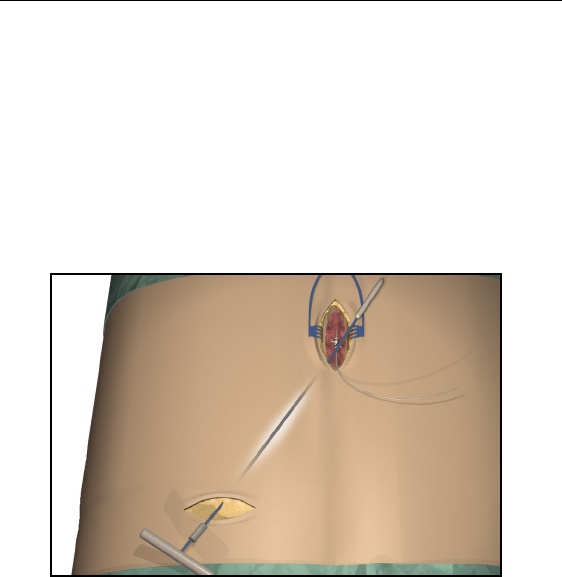
1. Ensure that the area surrounding the lead entry site is incised to a
dimension that will accommodate the tunneling tool. Check that
the lead is securely sutured with the suture sleeve.
2. Select and mark the intended IPG site several inches away from
the previously externalized leads, and create an incision at the top
of the implant site. (Common sites are the abdomen, upper but-
tock, or subclavicular area.)
3. Create a subcutaneous pocket no larger than the IPG outline at a
depth less than 3/4 inch (2.0 cm) from the surface.
Note: • Using the template will help guide the correct pocket sizing.
It is important to keep the pocket small to reduce the
chances of patient manipulation and IPG flipping.
•Implant charging could become ineffective at depths greater
than 3/4 inch (2.0 cm).
Guidelines for Permanent Implantation
23
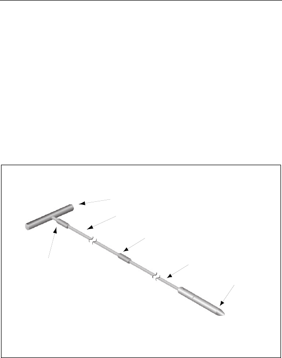
Tool Assembly
The tunneling tool provided with the IPG includes a shaft extender to
be used for up to two leads.
1. Attach the handle to the tunneling tool shaft by turning the lock-
ing mechanism clockwise.
Note: For more length, attach the shaft extension to the handle, and
then attach the carrier shaft.
2. Thread the tip cover onto the tunneling tool and tighten by turn-
ing clockwise.
Tunneling The Lead
1. Mark the desired route of the tunnel.
2. Administer the appropriate local anesthetic along the tunneling
path.
Tool Handle
Locking Mechanism
Locking Mechanism
Shaft Extension
Shaft
Carrier Tip Cover
24
Physician Implant Manual
Note: Check that the tunneling tool tip is securely threaded onto the
carrier.
3. OPTIONAL. If necessary, bend the tool shaft to conform to the
patient’s body.
CAUTION: Do not bend locking joints.
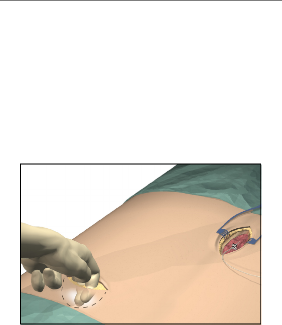
4. Create a subcutaneous tunnel from the IPG site to the midline
incision.
Note: Deep tunneling is not recommended.
Guidelines for Permanent Implantation
25
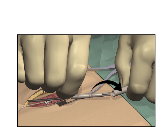
5. Once the tunneling tip is completely exposed at midline, press it
toward the shaft and turn it counterclockwise to remove it for
access to the carrier.
Note: You may feel the tip slide back before the cover begins to
unscrew.
26
Physician Implant Manual
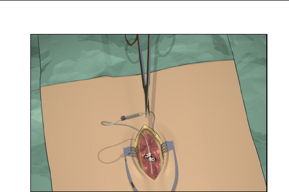
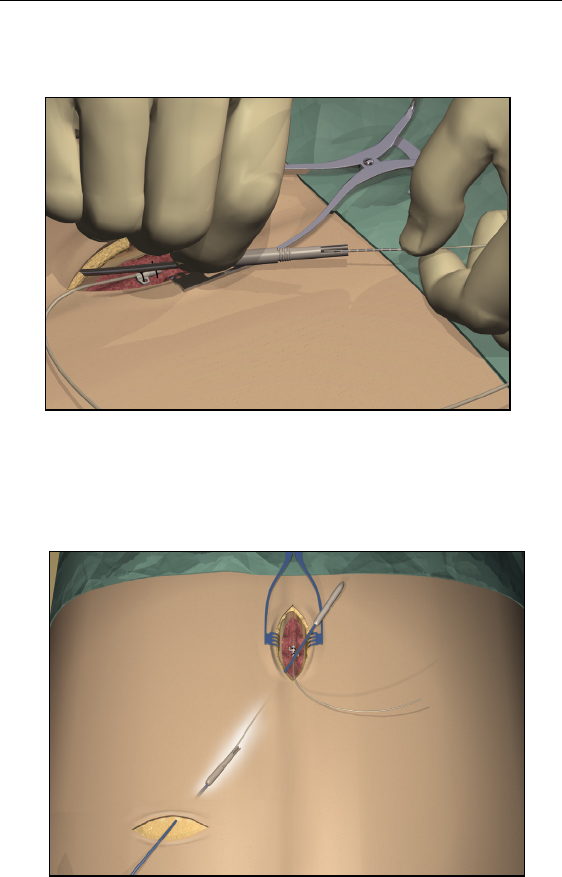
6. Carefully position each lead or extension into the carrier shaft
and press the lead/extension into the groove.
Note: If necessary, swivel the carrier by pulling it away from the
handle and turning it to get better access to the cavities.
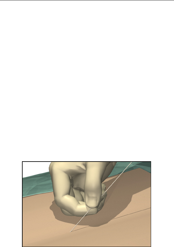
7. Gently pull the tunneling tool back through the tunnel.
Guidelines for Permanent Implantation
27
8. Gently lift the lead(s) out of the locking groove(s).
9. Wipe off any fluids from the proximal end of the lead(s).
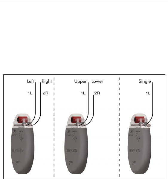
Connecting To the IPG
Dual Lead Connection
• Superior (upper or left) leads connect to IPG port 1-L.
• Inferior (lower or right) leads connect to IPG port 2-R.
Single Lead Connection
• Connect a single lead to IPG port 1-L.
• Plug port 2-R with the connector plug supplied in the
IPG Kit.
28
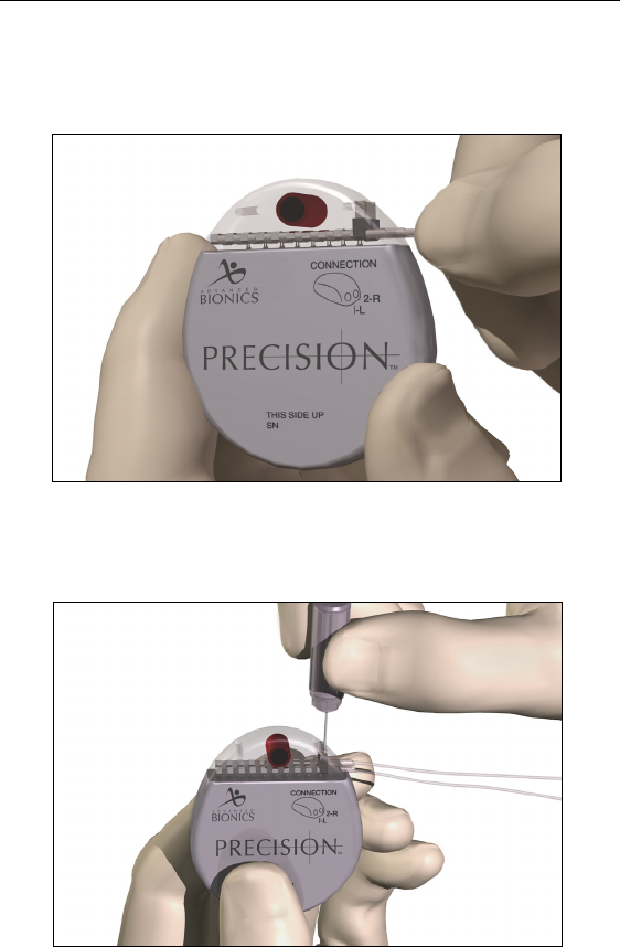
Physician Implant Manual
1. Fully insert the lead(s) into the IPG port(s). When the lead is
properly inserted, the lead will stop and the retention ring will be
located under the setscrew.
2. Pass the torque wrench through the slit in the septum located on
the top of the IPG header and tighten both set screws, one at a
time, until the torque wrench “clicks,” indicating lock.

Guidelines for Permanent Implantation
29
CAUTION: Ensure that the lead is fully inserted before tightening the
setscrew to prevent lead damage.
Note: • If the connector plug is used in port 2-R, it is still necessary
to tighten the setscrew as described.
•The wrench is torque-limited and cannot be overtightened.
•Ensure that the lead is fully inserted before tightening the
setscrew to prevent lead damage.
•If there appears to be an obstruction when inserting the
lead, lead extension, or connector plug, use the torque
wrench to loosen (counterclockwise) the setscrew and/or
gently rotate the lead to help advance the proximal end.
3. Place the IPG in the subcutaneous pocket with “This Side Up”
facing towards the skin.
4. Coil excess lead or extension under the IPG.
Note: To confirm good connections, check impedances before
tightening the setscrew.
5. Secure the IPG in the pocket by suturing through the holes in the
connector.
6. Close and dress the wound(s).

30
Physician Implant Manual
IPG Explant or Replacement
1. Turn off the IPG.
2. Surgically open the IPG pocket and withdraw the device.
3. Unscrew the connector setscrews to release and remove the leads.
4. For replacement, connect the new IPG following steps 1-6 of
“Connecting to the IPG,” preceding. Or, to terminate therapy, sur-
gically remove the implanted lead system.

Rechargable Implant System
31
Rechargable Implant System
The Precision spinal cord stimulator is rechargeable. Depending on
stimulation power usage and programming, the majority of patients
will need to recharge the implant once per week. High power users
will require more frequent charging. Advanced Bionics recommends
any recharge schedule (daily, bi-daily, weekly, bi-weekly) that fits the
patient’s schedule and lifestyle while maintaining sufficient charge to
maintain stimulation.
The Clinician Programmer will estimate charging time based on 24
hours per day of stimulation at the programmed settings. Recharge
time can range from ten minutes to four hours. Patients should be
instructed to charge until the Charger emits an end of charge beep sig-
nal. The recharging process is important, but simple.
The rechargeable implant battery should provide at least five years of
service. Over time and repeated charging, the battery in the implant
will lose its ability to recover its full capacity. As a result, the implant
may require increased recharge time and/or shorter intervals between
charges after five years of service. The implant will need replacement
when stimulation can no longer be maintained with routine charging.
IPG Battery Status
When the patient Remote Control communicates with the implant, the
battery status is sent to the remote, which will display a message
when the stimulator battery is low and when the stimulator battery is
empty. When the remote indicates a low battery (message: Recharge
Stimulator Soon) the implant should be recharged as soon as possible.
Failure to recharge will lead to loss of stimulation in less than 24
32
Physician Implant Manual
hours, and the implant will need to be charged for approximately two
hours before reactivation.
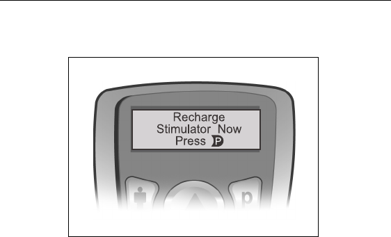
If the patient reports that stimulation has stopped but does not also
report having seen the Remote Control warning messages “Recharge
Stimulator Now” and “Must Recharge,” instruct the patient to check
the implant battery status with the Remote Control first. If the mes-
sage sequence is displayed, inform the user that the IPG must be
recharged within three days or he/she runs the risk of needing to
return to the clinic for reprogramming.
If the patient reports seeing a “No Response” message on the Remote
Control screen, the lack of communication is probably due to a low
battery. Instruct the patient to recharge the implant, and then try using
the remote again.
Charging Steps
The Charger Base Station should be plugged in and the charger placed
in the cradle until the indicator light is green. If the indicator is amber-
colored, the charger may not be able to fully charge the implant.
Users may wear the charger over the implant using a Velcro® belt or
adhesive patches. Advanced Bionics recommends using the Velcro®
belt for charging.

Rechargable Implant System
33
1. While the Charger is seated in the Base Station, check that the
indicator light is green.
2. Remove the Charger from the Base Station. (The indicator light
will go out, regardless of the ready status of the Charger.)
Note: If the implant is not recharged as recommended, stimulation
will eventually stop due to a low battery. If this happens, the
implant must be recharged within three days from loss of
stimulation. If stimulation stops and you have lost or cannot
get to your charger within five days, contact Customer Service
immediately at (866) 360-4747.
If discontinuing stimulation for an extended period of time, the
implant should first be fully charged. Additionally, the implant
should be fully charged every month if stimulation is not used.
34
Physician Implant Manual
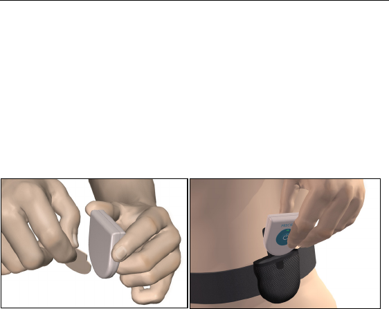
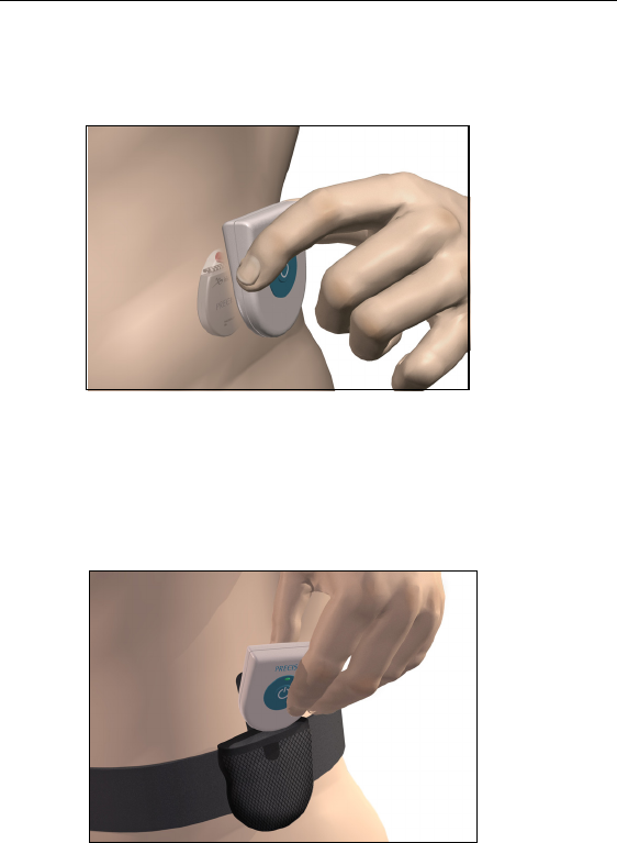
3. Apply the adhesive to the backside of the Charger by peeling the
clear device side liner from the patch and applying the patch to
the device, as shown, and then remove the skin side beige liner
from the adhesive (only good for one fixation).
OR
Place the Charger into the Velcro® belt with the power button
facing out.
4. Press the power button, the large blue center of the Charger, to
turn on the Charger. The indicator light will return to the status
color (green or amber), and the Charger will begin beeping
steadily to signal that it is searching for the implant.
Rechargable Implant System
35
5. Locate the Charger over the IPG. When the Charger is correctly
aligned with the IPG, the beeping will stop. Press the Charger
with the adhesive, or secure the Velcro® belt at this time.
Note: • If the Charger loses contact with the IPG during charging,
the steady alignment beep will sound. Readjust the belt or
reapply the adhesive.
6. When the Charger emits a distinct double beep, the implant is
charged.
36
Physician Implant Manual
Patient Remote Control
Basic Operation
The Remote Control communicates with the implant through a radio
frequency (RF) telemetry link from a distance of up to two feet. When
it is not being used, the remote is in an idle (or sleep) mode from
which it can be reactivated by any button press. During normal patient
use, the device will transition to idle mode automatically after 60 sec-
onds of non-use.
Some remote functions (i.e., patient Options and Clinician Mode) are
accessed via a “long button press” (press and hold for approximately
three seconds). These are identified in the appropriate sections fol-
lowing.
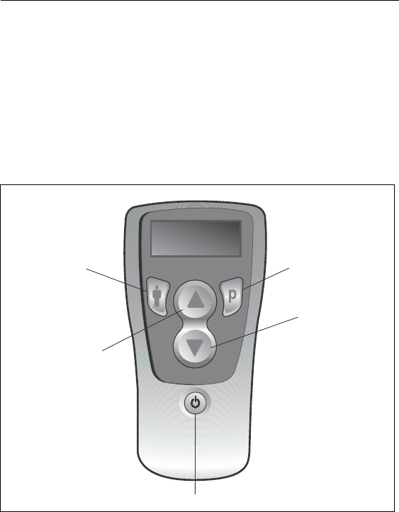
Program Button
Area Button
Stimulation On/Off Button
Up/Activate
Down/Save
Patient Remote Control
37
Stimulation On/Off
Stimulation is turned on and off via a dedicated power switch on the
Remote Control keypad. Simply press the stimulation on/off button at
any time to change the stimulation status of the implant.
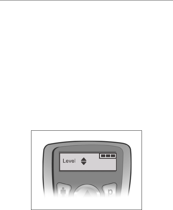
Stimulation Amplitude
The Level screen is the Remote Control’s “default” screen. The
remote will automatically return to this screen within 15 seconds of
any button activity.
Note: When there is no button activity for more than 60 seconds, the
Remote Control will transition to idle mode and the display
screen will be blank.
Press the S or T button from the Level screen to decrease or
increase amplitude.
The Level screen also displays a bar graphic in the upper right corner
to indicate the battery charge level of the implant. Three filled-in bars
represents a fully-charged battery. As the battery strength is reduced,
depending on the patient’s stimulation settings and usage, the bars
will “empty” accordingly. Patients are encouraged to recharge the
implant at the first “Recharge Battery Soon” message displayed by
the Remote Control.
38
Physician Implant Manual
Coverage Area Selection
1. Press the Cbutton as needed from the Level screen to cycle to a
specific stimulation coverage area.
2. Press the S or T button to adjust the amplitude of the selected
area.
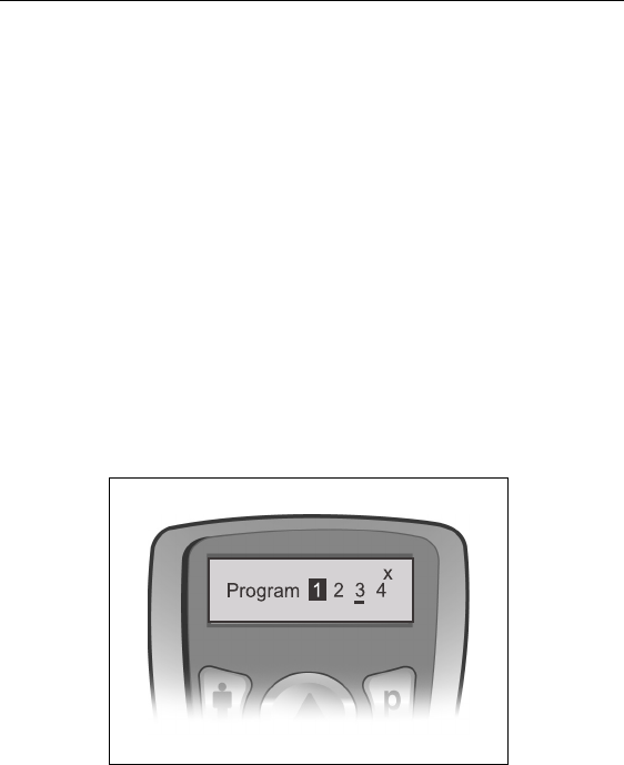
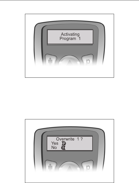
Program Selection
Note: The most recently retrieved or saved program will be
underlined. Empty program slots are denoted by an X.
1. Press the Dbutton as needed from the Level screen to cycle to a
specific saved program.
2. Press S to activate the selected program.
Modifying and Saving Programs
1. Press Das needed from the Level screen to cycle to the desired
program.
Note: The most recently retrieved or saved program will be
underlined. Empty program slots are denoted by an X.
Patient Remote Control
39
2. Press S to activate the selected program.
3. After the remote times out to the Level screen, you may change
the amplitude of all areas in the program, or you may adjust the
Rate or Pulse Width of an individual area by navigating to the
Options settings (see “Options” on page 40).
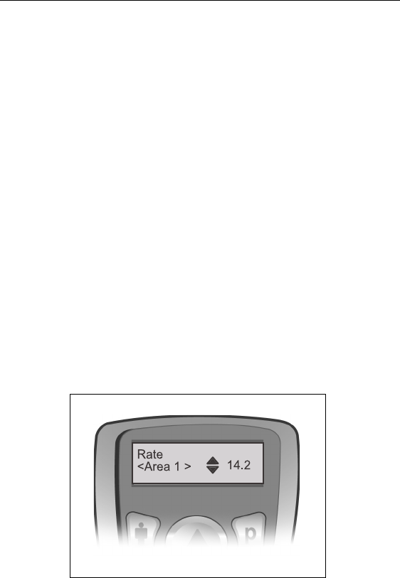
4. To save/store changes, select the program again and press T.
You will be required to confirm the adjustment first.
5. Press Dto confirm, or press the Cbutton to cancel the opera-
tion.
40
Physician Implant Manual
Note: To save the modifications as a new program, simply select an
empty (X) program slot and press Tinstead of overwriting the
existing program.
Options
With the Precision SCS system, the Rate and Pulse Width parameters
are generally considered programming “options” in that relatively few
patients will actually use these settings. By default, Rate and Pulse
Width are off-limits to the patient Remote Control unless you allow
access using BionicNavigator software.
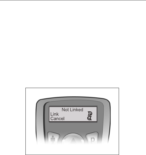
Another option, “Restore,” is readily available to all patients. The
Restore feature allows patients to return a program to the original set-
tings you programmed for them at the initial fitting or at a follow-up.
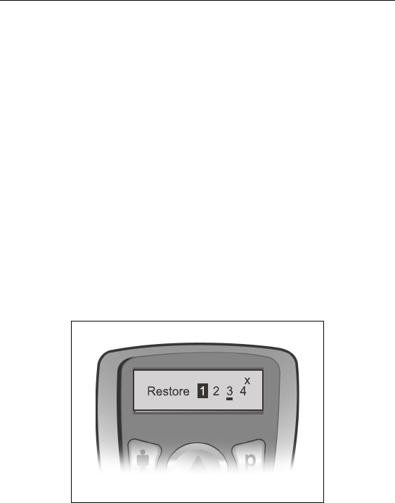
To Access the Rate and Pulse Width Options:
1. Press and hold the Cbutton for three seconds (a long button
press) or until the Rate Area 1 screen appears.
2. As necessary, press the Cbutton normally to cycle to the area
you wish to adjust.
Patient Remote Control
41
3. When the desired area screen is displayed, press S or T to
increase or decrease the Rate.
4. To continue with a Pulse Width adjustment, press and hold the
Area button from any Rate Area screen to navigate to Pulse
Width Area 1.
5. As necessary, press the Cbutton normally to cycle to the area
you wish to adjust.
6. When the desired area screen is displayed, press S or T to
increase or decrease the Pulse Width.
To Access the Restore Option
1. Press and hold Dto reach Restore Program 1.
2. If necessary, press the Dbutton again (normal press) to cycle
through the programs and select the program to be restored.
3. Press S to restore the last clinic-programmed settings..
Device Linking
A Remote Control can communicate with only one stimulator at a
time. This prevents the remote from accidentally controlling an unin-
tended device. For this reason, the initial step in the linking process
involves the Remote Control identifying, by telemetry, the intended
42
Physician Implant Manual
stimulator for communication.The second step in establishing the link
depends on:
• Whether the stimulator is an External Trial Stimulator
(ETS) or an IPG;
• Whether the Remote Control or the stimulator has
stored programs or whether they are clear of programs;
• Where a different program set is present in both devices,
which set is to be cleared.
An un-linked Remote Control will display the following message
upon first activation (when any button is pressed) or immediately fol-
lowing a de-linking action:
Patient Remote Control
43
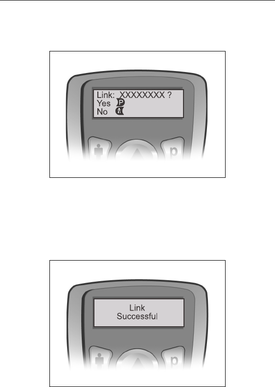
1. Press Dto initiate communication between the remote and the
stimulator within telemetry range. The remote will identify the
device by ID number.
2. Press Dto confirm and continue.
The Precision system software will automatically detect whether the
stimulator is a trial or a permanent device, and whether program sets
are available and where. If both the Remote Control and the target
stimulator are clear of programs, the link is completed immediately
and you will see this message:
However, if programs are present in either device during linking, you
will be required to respond to one or more “decision” screens to guide
the remote to complete the linking with the desired program set saved
44
Physician Implant Manual
to the desired device (remote or stimulator). You may also need to
enter the clinician’s password.
If an error occurs during the process or if the password is incorrect
linking will be aborted. For further information, including informa-
tion about the clinician’s password, see “To Clear Link” following.
Clinician Options
Patient-restricted clinician screens provide access to:
• Remote Control and stimulator clearing and relinking
• Communication with the clinician programmer
• Electrode impedance monitoring
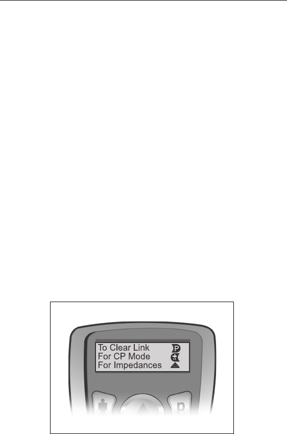
To access clinician screens:
1. Press the Cand Dbuttons simultaneously for approximately
three seconds. The Enter Clinician Options screen will appear as
shown below.
2. Press the appropriate button to select an option.
Each option is discussed in sequence below.
Patient Remote Control
45
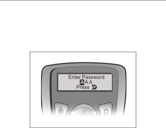
To Clear Link
When the Dbutton is pressed from the Enter Clinician Options
screen, you will immediately be required to enter the clinician’s pass-
word in order to continue.
To enter the password:
The first character is highlighted when the Enter Password screen
opens. To select/confirm any character and/or move to the next char-
acter position, press D. To scroll through possible characters, use S
or T.
46
Physician Implant Manual
When clearing a link: If the password is entered correctly, the link
between the Remote Control and the “previous” stimulator is broken
immediately , and the remote displays the Not Linked screen. The
Remote Control’s programs remain intact. If the password is entered
incorrectly, the process is aborted and the remote will return to the
Enter Clinician Options screen.
Note: If the password is entered incorrectly during an attempt to link
the Remote Control, the process is aborted and the remote
returns to the Idle screen.
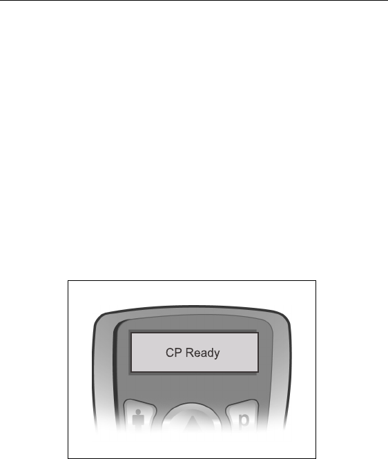
For CP Mode
1. From the Enter Clinician Mode screen (See page 44), press the
C button to prepare the Remote Control for communication with
the Clinician’s Programmer (CP).
Note: The remote will remain CP Ready for 15 minutes.
Patient Remote Control
47
2. Place the remote and the IR dongle in the IR Holder with their
communication ports facing.
3. Plug the dongle’s USB connector into the slot in the CP and
power-on the programmer.
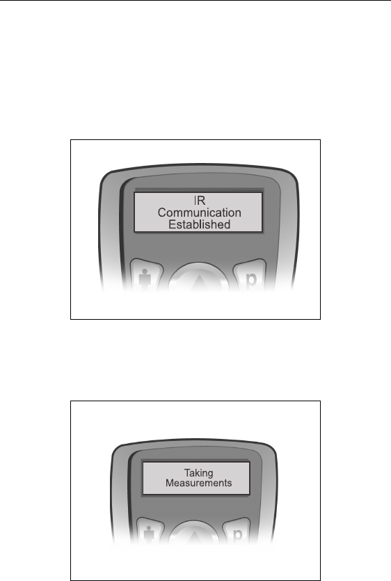
4. Launch the BionicNavigator software and wait for the IR Com-
munication Established display.
For Impedances
When S is selected from the Enter Clinician Options screen, the
Remote Control will take the measurements via telemetry; this will
take a few seconds.
48
Physician Implant Manual
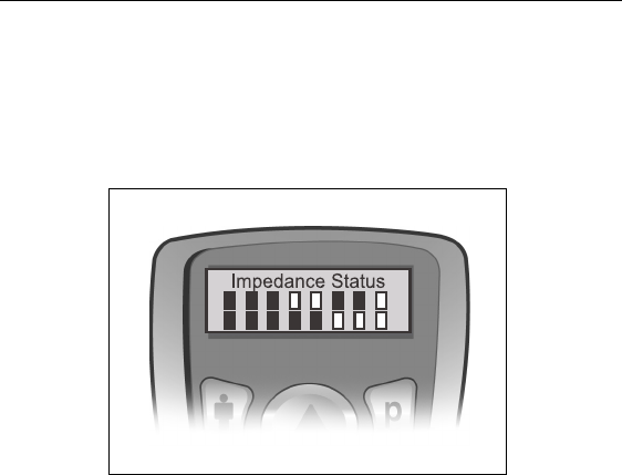
Eventually, the remote will display the Electrode Impedance Sta-
tus screen.
Electrodes 1 through 8 (lead position 1-L) are represented by the
rectangles in the top row; electrodes 9 through 16 (lead position
2-R) are represented by the rectangles in the bottom row.
Electrodes within the acceptable impedance range are displayed as
solid rectangles; high impedance electrodes (above 4500 ohms) are
represented by hollow rectangles.
Note: • The Remote Control will terminate the CP Ready state and
transition to the idle mode if there is no IR signal after 15
minutes.
•All buttons are active during CP Ready and pressing any
button returns the Remote Control to the Level screen.
•Stimulation may be turned on or off during CP Ready.
•Once IR Communication is established, the Remote Control
will terminate communication and transition to the idle
mode if there is no IR activity after 15 minutes.
•All buttons are active during IR Communication and press-
ing any button returns the Remote Control to the Level
screen.

Patient Remote Control
49
•Whenever the remote is re-activated from idle mode the dis-
play will default to the Level screen.
Programmer Communication
The Clinician Programmer can communicate with either an External
Trial Stimulator or an IPG. In order to begin a programming session,
the CP and the Remote Control IR windows must be aligned.
Arrange for the patient to be seated within two feet of the Remote
Control to ensure a complete communication link from the program-
mer to the stimulator.
For instructions on how to use the Clinician Programmer with the
BionicNavigator software to program the IPG and transfer programs
to the Remote Control, see the BionicNavigator Software Guide.

50
Physician Implant Manual
Specifications and Technical Data
Materials
Parameter Range Default
Areas (Channels) 4 —
Amplitude 0 – 20 mAa
a.The Precision System includes programmable cover-
age areas with each individual electrode contact limited
to 12.7 mA. A programming interlock is enforced to
limit the coverage area output current to 20 mA or less.
For example, a maximum current output of 12.7 mA on
a first electrode would limit the total summed current
output on remaining electrodes to 7.3 mA within one
coverage area.
0 mA
Rate 0 – 1200 ppsb
b.Only one Area is available if the rate is 130 pps.
40 pps
Width 0 – 1000 µsec 210 µsec
Cycle 0 – 90 min, OFF OFF
Ramp ON 1 – 10 secs 3 secs
Contacts 1 – 16; +, -, OFF 1 – 16: OFF
Case Titanium
Header Epoxy
Strain Relief Silicone
Size/Volume 55mm x 45mm x 11mm / 22 cm3 (including header)
Maximum Current Amplitude per Electrode versus Impedance
51
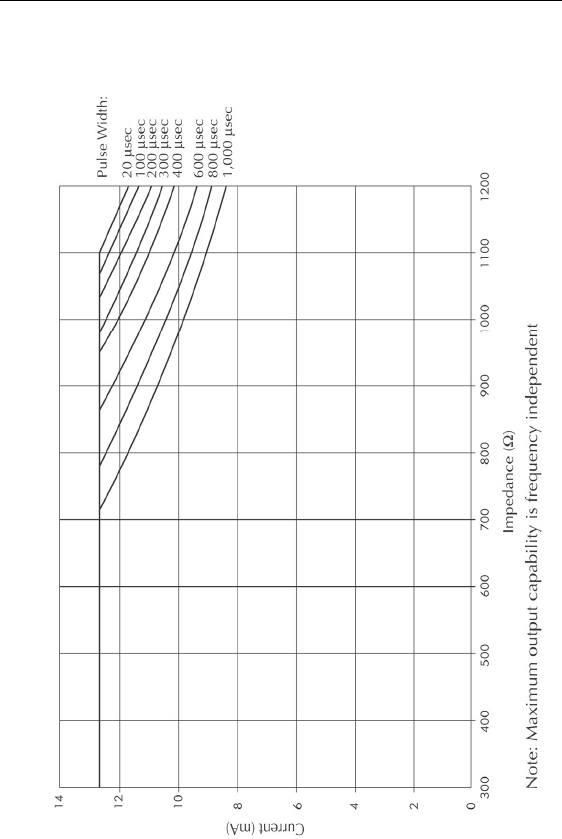
Maximum Current Amplitude per Electrode versus Impedance

52
Physician Implant Manual
Registration Information
Registering the Implant
In accordance with international practice and regulatory legislation in
some countries, a registration form is packed with each Advanced
Bionics Corporation neurostimulator.
The purpose of this form is to maintain traceability of all products and
to secure warranty rights. It also allows the institution involved in the
evaluation or replacement of a specific implanted lead, accessory or
device to gain quick access to pertinent data from the manufacturer.
Fill out the registration form included in the package contents. Return
one copy to Advanced Bionics, keep one copy for patient records, and
provide one copy to the patient and physician.
Advanced Bionics Corporation
25129 Rye Canyon Loop
Valencia, California 91355
Attention: Customer Service Department

Technical Service
53
Technical Service
Advanced Bionics Corporation has highly trained service profession-
als located worldwide to assist you. The Technical Service Depart-
ment is available to provide technical consultation 24 hours a day.
In North America, please call (866) 566-8913 to speak to a represen-
tative.

54
Physician Implant Manual
Limited Warranty
Advanced Bionics® Corporation (hereinafter referred to as Advanced
Bionics®) warrants to the patient who receives a Precision™ System
that the implanted pulse generator (hereinafter referred to as the IPG,
Model SC 1110, is free from defects in workmanship and materials
for a period of one (1) year from the date of surgical implant of the
IPG. This warranty only applies to the patient (recipient, hereinafter
referred to as the patient), and no other individual.
An IPG that fails to function within normal tolerances within (1) year
from the date of surgery is covered under this Limited Warranty. The
liability of Advanced Bionics® under this warranty shall be limited to:
(a) replacement with a functionally equivalent IPG; or (b) full credit
equal to the original purchase price to be applied towards the purchase
of a new IPG. Product claims under Advanced Bionics® Limited War-
ranty are subject to the following conditions and limitations:
1. The product registration card must be completed and returned to
Advanced Bionics® within 30 days of surgery in order to obtain
warranty rights.
2. The IPG must be returned to Advanced Bionics® (or authorized
agent) within 30 days of malfunction or discovery of defect, and
shall be the property of Advanced Bionics®.
3. The IPG must be implanted prior to the “use before” date.
4. Failure of the IPG must be confirmed by Advanced Bionics®.
This warranty specifically excludes defects or malfunctions
caused by: (a) fire, floods, lightning, natural disasters, water
damage and other calamities commonly defined as “Acts of
God”; (b) accident, misuse, abuse, negligence, or the customer’s
failure to operate the IPG in accordance with manufacturer's
instructions; (c) unauthorized attempts to repair, maintain, or
modify the equipment by the customer or any unauthorized third
party; or (d) attachment of any equipment not supplied by
Advanced Bionics® without prior approval.

Limited Warranty
55
a. This warranty does not include the leads, extensions or
surgical accessories used with the Precision™ IPG.
5. The decision as to product replacement or credit shall be made
solely at the discretion of Advanced Bionics®. For a replacement
IPG, the warranty will run only to the end of the warranty period
for the original IPG that was replaced.
This warranty is in lieu of any other warranty, expressed or implied,
including any warranty of merchantability or fitness for intended use.
Except as expressly provided by this Limited Warranty, Advanced
Bionics® shall not be responsible or liable for any direct, consequen-
tial or incidental damages caused by device malfunction, failure or
defect, whether the claim is based on warranty, contract, tort or other-
wise.

56
Physician Implant Manual
The following is federal government communications regulation
information about the Precision™ System.
This device complies with part 15 of the FCC Rules. Operation is sub-
ject to the following two conditions: (1) This device may not cause
harmful interference, and (2) This device must accept any interfer-
ence received including interference that may cause undesired opera-
tion.
The Precision™ System components should only be serviced by
Advanced Bionics. Do not attempt to open or repair any of the com-
ponents. Unauthorized opening of or attempts to repair the compo-
nents will void the warranty.
Changes of modifications to this product not authorized by Advanced
Bionics Corporation could void the FCC Certification and negate
your authority to operate this product.