Boston Scientific CRMN11906 Implantable Defibrillator User Manual Cognis Part 2 Manual fccid
Boston Scientific Corporation Implantable Defibrillator Cognis Part 2 Manual fccid
Contents
- 1. Cognis Part 1 Manual
- 2. Cognis Part 2 Manual - fccid
- 3. Cognis Part 3 Manual
- 4. Cognis Part 4 Manual
- 5. Teligen Part 1 Manual
- 6. Part 2 Teligen Manual
Cognis Part 2 Manual - fccid
TACHYARRHYTHMIA DETECTION
VENTRICULAR DETECTION 3-35
When a detection window becomes satisfied, the pulse generator begins
calculating for sudden Onset in a two-stage sequence.
• Stage 1 measures the ventricular intervals prior to the start of the episode
and locates the pair of adjacent intervals (pivot point) where the cycle
length decreased the most. If the decrease in cycle length is equal to or
greater than the programmed Onset value, stage 1 declares sudden Onset.
• Stage 2 then compares additional intervals. If the difference between the
average interval before the pivot point and 3 out of the first 4 intervals
following the pivot point is equal to or greater than the programmed Onset
Threshold, stage 2 declares sudden Onset.
If both stages declare the rhythm sudden, therapy will be initiated. If either
stage indicates a gradual onset, initial ventricular therapy will be inhibited in the
lowest zone. Therapy will not be inhibited by Onset if:
• The rate accelerates to a higher ventricular zone
• Information from the atrial lead determines that the RV rate is faster than
theatrialrate(VRate>ARateprogrammedtoOn)
• The SRD timer expires
Onset is measured using RV intervals only. It can be programmed as a
percentage of cycle length or as an interval length (in ms). It is limited to the
lowest therapy zone of a multi-zone configuration. The selected Onset value
represents the minimum difference that must exist between intervals that are
above and below the lowest programmed rate threshold. The pulse generator
performs Onset calculations (even when the feature is programmed to Off) for
all episodes except induced or commanded episodes. The measured Onset
results from a two-stage calculation are stored in therapy history. This stored
data may be used to program an appropriate Onset value.
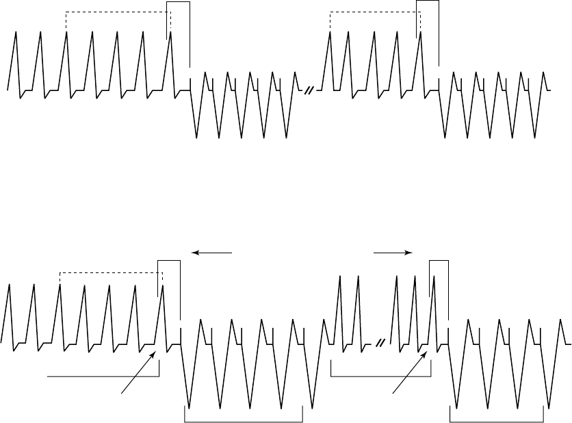
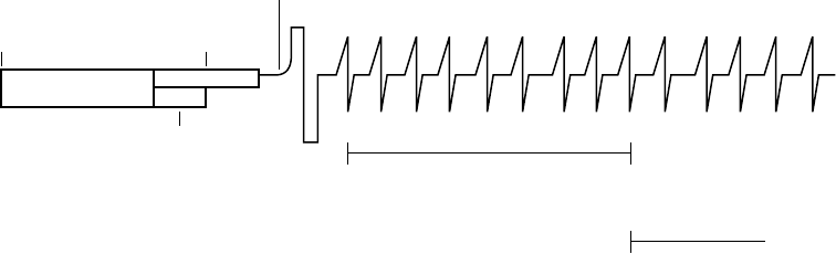
Sustained Rate Duration (SRD)
Sustained Rate Duration allows delivery of the programmed ventricular therapy
when a tachycardia is sustained for a programmed period beyond Duration, but
the programmed therapy inhibitors (Vector Timing and Correlation, AFib Rate
Threshold, Onset, and/or Stability) indicate to withhold therapy (Figure 3-21 on
page 3-36).
- DRAFT -

3-36 TACHYARRHYTHMIA DETECTION
VENTRICULAR DETECTION
0 s 5 s 35 s
0 s 30 s
Duration = 5 seconds
SRD = 30 seconds
Evaluate programmed detection
enhancements. If enhancements
indicate to inhibit therapy, start
SRD timer; otherwise, deliver
therapy.
Continue detection
enhancement
analysis throughout
SRD time.
If detection
enhancements
indicate therapy,
deliver therapy.
SRD times out.
Deliver therapy.
Detection window
satisfied
Duration starts. Start
detection enhancement
analysis.
Duration expires.
Figure 3-21. Combination of Onset OR Stability, SRD programmed on
SRD is available in a zone only when an inhibitor enhancement is programmed
on in that zone. When the Rhythm ID detection enhancement suite is enabled,
SRD may be programmed separately for the VT and VT-1 zones.
• If an inhibitor is withholding ventricular therapy delivery and the Rate
criterion in the lowest zone is maintained, the programmed SRD timer
begins at the end of the first zone’s completed Duration.
• If the detection window in the lowest zone is maintained for the programmed
SRD period, the programmed ventricular therapy will be delivered at the
end of the VT-1 SRD period if VT-1 SRD is programmed and the rhythm
is in the VT-1 zone. Therapy will be delivered at the end of the VT SRD
period if VT SRD is programmed and the rhythm is in the VT zone.
• If the rate accelerates to a higher ventricular zone, detection enhancements
are not programmed to On in the higher zone, and the Duration for the
higher zone expires, therapy is initiated in that zone without waiting for
SRD time-out in a lower ventricular zone. If SRD is programmed to Off,
an SRD timer will not start when Duration expires, thus allowing detection
enhancements to potentially inhibit therapy indefinitely.
An independent Post-Shock SRD value may be programmed.
Combinations of AFib Rate Threshold, Stability, and Vector Timing and
Correlation
The combination of AFib Rate Threshold, Stability, and Vector Timing and
Correlation add specificity to ventricular detection beyond rate and duration.
In addition to using AFib Rate Threshold and Stability to identify AF, this
combination of enhancements uses Vector Timing and Correlation analysis
to differentiate SVT rhythms from VT rhythms based on conduction patterns
within the heart.
- DRAFT -

TACHYARRHYTHMIA DETECTION
VENTRICULAR DETECTION 3-37
The AFib Rate Threshold, Stability, and Vector Timing and Correlation detection
enhancement combination also includes V Rate > A Rate; both AFib Rate
Threshold and V Rate > A Rate are enabled when Atrial Tachyarrhythmia
Discrimination is programmed to On. This combination is only available when
the Rhythm ID detection enhancement suite is enabled, and only for Initial
Detection(Table3-11onpage3-37).
If V Rate > A Rate is programmed to On (by programming Atrial
Tachyarrhythmia Discrimination to On) and is True, it will take precedence over
all inhibitor enhancements.
Table 3-11. AFib Rate Threshold, Stability, and Vector Timing and Correlation combinations and resulting
therapy decision if Atrial Tachyarrhythmia Discrimination is programmed to On
Detected Ventricular Rhythmabc Therapy Decisiond
Correlated, Unstable, A > AFib Rate Threshold Inhibit
Correlated, Unstable, A < AFib Rate Threshold Inhibit
Uncorrelated, Unstable, A > AFib Rate Threshold Inhibit
Uncorrelated, Unstable, A < AFib Rate Threshold Treat
Correlated, Stable, A > AFib Rate Threshold Inhibit
Correlated, Stable, A < AFib Rate Threshold Inhibit
Uncorrelated, Stable, A > AFib Rate Threshold Treat
Uncorrelated, Stable, A < AFib Rate Threshold Treat
a. If the detected ventricular rhythm changes, then the appropriate, corresponding row in the table is evaluated.
b. If a Rhythm ID reference template is not available, the detected ventricular rhythm is considered to be Uncorrelated.
c. For post shock detection (if enabled), Vector Timing and Correlation is considered to be Uncorrelated.
d. Decisions to inhibit can be overridden by V > A or expiration of SRD.
When Atrial Tachyarrhythmia Discrimination is programmed to Off, then Vector
Timing and Correlation is used for Initial Detection and Stability is used for
Post-shock detection. V Rate > A Rate and AFib Rate Threshold are no longer
used (Table 3-12 on page 3-37).
Table 3-12. Vector Timing and Correlation and Stability combinations with resulting therapy decision if Atrial
Tachyarrythmia Discrimination is programmed to Off
Detectionab Dectected Ventricular
Rhythmac
Therapy Decision
Initial Correlated Inhibitd
Initial Uncorrelated Treat
- DRAFT -

3-38 TACHYARRHYTHMIA DETECTION
VENTRICULAR DETECTION
Table 3-12. Vector Timing and Correlation and Stability combinations with resulting therapy decision if Atrial
Tachyarrythmia Discrimination is programmed to Off (continued)
Detectionab Dectected Ventricular
Rhythmac
Therapy Decision
Post-shock Unstable Inhibitd
Post-shock Stable Treat
a. If the detected ventricular rhythm changes, then the appropriate, corresponding row in the table is evaluated.
b. If Atrial Tachyarrhythmia Discrimination is programmed to Off, then Vector Timing and Correlation is used for Initial Detection,
and Stability is used for Postshock Detection.
c. If a Rhythm ID reference template is not available, the detected ventricular rhythm is considered to be Uncorrelated.
d. Decision to inhibit can be overridden by expiration of SRD.
Combinations of AFib Rate Threshold, Stability, and Onset
The combination of AFib Rate Threshold, Stability, and Onset add specificity
to ventricular detection beyond rate and duration. This combination of
detection enhancements is available only when the Onset/Stability detection
enhancement suite is enabled and is available only for Initial Detection. When
detection enhancements are enabled, they will act to recommend or inhibit
therapy for a specific zone.
If AFib Rate Threshold, Stability, and Onset parameters are all programmed
to On, ventricular therapy will be initiated if the rhythm has a sudden onset
provided that either the ventricular rate is stable or the atrial rate is less than
the AFib Rate Threshold (Table 3-13 on page 3-38).
Table 3-13. AFib Rate Threshold, Stability, and Onset combinations and resulting ventricular therapy
Detected Ventricular RhythmaTherapy Decisionb
Gradual, Unstable, A > AFib Rate
Threshold
Inhibit
Gradual, Unstable, A < AFib Rate
Threshold
Inhibit
Sudden, Unstable, A > AFib Rate
Threshold
Inhibit
Sudden, Unstable, A < AFib Rate
Threshold
Treatc
Gradual, Stable, A > AFib Rate Threshold Treat
Gradual, Stable, A < AFib Rate Threshold Inhibit
Sudden, Stable, A > A Fib Rate Threshold Treat
Sudden, Stable, A < AFib Rate Threshold Treat
a. If the detected ventricular rhythm changes, then the appropriate, corresponding row in the table is evaluated.
b. Decisions to inhibit can be overridden by V > A or expiration of SRD.
c. If V Rate > A Rate is programmed to On and is False, ventricular therapy will be inhibited because the rhythm is unstable.
- DRAFT -

TACHYARRHYTHMIA DETECTION
VENTRICULAR DETECTION 3-39
If V Rate > A Rate is programmed to On and is True, it will take precedence
over all inhibitor enhancements.
Combinations of Onset and Stability
When Stability is programmed to inhibit, it may be combined with Onset to
provide even greater specificity in classifying arrhythmias.
This combination of detection enhancements is available only when the
Onset/Stability detection enhancement suite is enabled and is available only for
Initial Detection. The enhancements can be programmed to initiate ventricular
therapy if the following options are selected (Table 3-14 on page 3-39):
• Both Onset And Stability indicate to treat
• Either Onset Or Stability indicates to treat
Based on these programming decisions, ventricular therapy is inhibited when
any of the following criteria is met:
• If the combination programmed is Onset And Stability, ventricular therapy
is inhibited if either parameter indicates that therapy should be withheld;
that is, the rhythm is gradual Or unstable (the And condition to treat is
not satisfied).
• If the combination programmed is Onset Or Stability, ventricular therapy is
inhibited immediately at the end of Duration only if both parameters indicate
that therapy should be withheld; that is, the rhythm is gradual and unstable
(the Or condition to treat is not satisfied).
In either case, ventricular therapy will be initiated only if the And/Or conditions
to treat are satisfied. When these two combinations (And/Or) are used in
conjunction with SRD, and the And/Or conditions are not satisfied, ventricular
therapy will be inhibited until V Rate > A Rate is True or SRD times out
(Table 3-14 on page 3-39).
Table 3-14. Combinations of Onset And Stability and resulting therapy
Detection
Rhythm
Onset And Stability Combinationab Onset Or Stability Combinationc
Gradual, unstable Inhibit Inhibit
Gradual, stable Inhibit Treat
- DRAFT -

3-40 TACHYARRHYTHMIA DETECTION
VENTRICULAR DETECTION
Table 3-14. Combinations of Onset And Stability and resulting therapy (continued)
Detection
Rhythm
Onset And Stability Combinationab Onset Or Stability Combinationc
Sudden, unstable Inhibit Treat
Sudden, stable Treat Treat
a. If the detected ventricular rhythm changes, then the appropriate, corresponding row in the table is evaluated.
b. The And combination is the nominal setting when both are enabled.
c. Decisions to inhibit can be overridden by V > A or expiration of SRD.
- DRAFT -

4-1
TACHYARRHYTHMIA THERAPY
CHAPTER 4
This chapter contains the following topics:
• "Ventricular Therapy" on page 4-2
• "Antitachycardia Pacing Therapies and Parameters" on page 4-10
• "Ventricular Shock Therapy and Parameters" on page 4-21
- DRAFT -
4-2 TACHYARRHYTHMIA THERAPY
VENTRICULAR THERAPY
VENTRICULAR THERAPY
The pulse generator can deliver the following types of therapy to terminate
VT or VF:
• Antitachycardia pacing (ATP)
• Cardioversion/defibrillation shocks
ATP pacing schemes are bursts of pacing pulses delivered between the
ventricular pace/sense electrodes. Shocks are high-voltage biphasic pulses
delivered through the shocking electrodes synchronously with detected heart
activity.
NOTE: Tachycardia therapy decisions are based on cardiac cycle length by
using RV sensed events only.
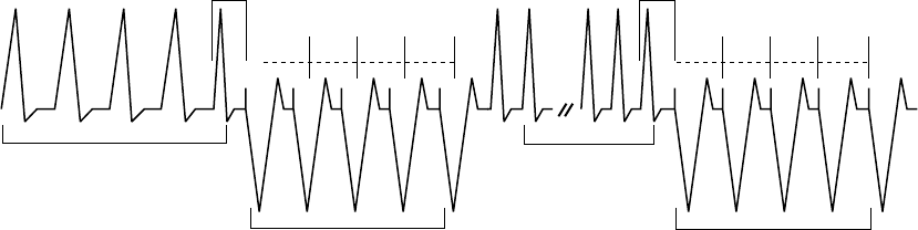
Ventricular Therapy Prescription
A ventricular therapy prescription determines the type of therapy to be
delivered in a particular ventricular rate zone. It consists of ventricular ATP
and/or shocks. Each ventricular zone may be programmed with independent
ventricular therapy prescriptions (Figure 4-1 on page 4-2).
Lowest strength Highest strength
Wi
t
hi
n eac
h
zone, t
h
erapy strengt
h
must
b
e
i
n ascen
di
ng or
d
er.
Zone ATP12 ATP22 QUICK
CONVERT ATP
Shock 11 Shock 21 Remaining (Maximum)
Shocks1
VF
VT
VT-1
Not available
All ATP types
available
On/Off
N/A
N/A
0.1-max J
0.1-max J
0.1-max J
0.1-max J
0.1-max J
0.1-max J
max J
max J
max J
All ATP types
available
All ATP types
available
All ATP types
available
Between
zones,
therapy
strengths
are not
restricted.
1 In the lowest zone of a multi-zone configuration, some or all of the shocks may be programmed to Off, starting with the maximum shocks
first. If the maximum shocks are programmed to Off, then Shock 2 can be programmed to Off. If Shock 2 is programmed to Off, then
Shock 1 can be programmed to Off. If the arrhythmia persists in the lowest zone when some or all of the shocks are programmed to Off,
no further therapy will be delivered unless the arrhythmia accelerates to a higher zone. A Disable Therapy button is available in the VT or
VT-1 zones’ therapy window to quickly disable all ATP and Shock therapy in that zone.
2 Ventricular ATP therapy can be programmed as Off, Burst, Ramp, Scan, or Ramp/Scan in VT-1 and VT zones.
Figure 4-1. Ventricular therapy prescription, 3-zone configuration
The therapies within a ventricular zone must be ordered in ascending therapy
strengths. All ventricular ATP therapies are considered to be of equal strength,
but are of lower strength than any shock therapy. The strength of the
shock therapies is determined by the programmed energy. In a multi-zone
- DRAFT -
TACHYARRHYTHMIA THERAPY
VENTRICULAR THERAPY 4-3
configuration, therapies in a higher ventricular zone may be of lesser, greater,
or equal strength to those in a lower ventricular zone; however, within each
zone the therapies must be programmed in equal or increasing energy output.
Ventricular Therapy Selection
The pulse generator determines which ventricular therapy to deliver based
on the following rules:
• Each successive therapy delivery must be greater than or equal to the
strength of the previous therapy in a ventricular episode. Whenever a
ventricular shock therapy has been delivered, no further ventricular ATP
therapy is allowed in that episode since ATP therapy is of lower strength
than shock therapy. Each subsequent ventricular shock delivery must be of
equal or greater strength regardless of ventricular zone changes during a
ventricular episode.
• Each ventricular ATP scheme (which may consist of multiple bursts) can
only be delivered once during a ventricular episode.
• Up to 8 shocks may be delivered in a ventricular episode. The first 2 shocks
are programmable. The following maximum-energy, non-programmable
shocks are available in each zone:
– VT-1 zone: 3 maximum-energy shocks
– VT zone: 4 maximum-energy shocks
– VF zone: 6 maximum-energy shocks
NOTE: In the event a shock is diverted with the DIVERT THERAPY
programmer command, by magnet application or due to a Diverted-Reconfirm,
the diverted shock is not counted as one of the available shocks for that
tachyarrhythmia episode. Also, commanded therapies and STAT SHOCK are
not counted as one of the available shocks for an episode and do not affect
subsequent therapy selection.
Based on initial ventricular detection criteria, the pulse generator selects the
first prescribed therapy in the ventricular zone in which the tachyarrhythmia
is detected (i.e., detection is met; see "Ventricular Detection" on page 3-6).
After delivering the selected therapy, the pulse generator begins redetection to
determine whether the arrhythmia has been converted.
- DRAFT -
4-4 TACHYARRHYTHMIA THERAPY
VENTRICULAR THERAPY
• If the arrhythmia is converted to a rate below the lowest programmed
threshold, the pulse generator continues monitoring until the end of the
episode is declared. When the episode ends, the pulse generator will again
use initial ventricular detection criteria for a new episode. When a new
episode is declared, the first prescribed therapy will be delivered again.
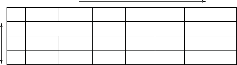
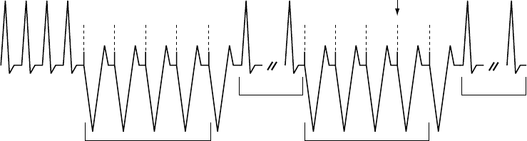
• If the arrhythmia is not converted and an arrhythmia is redetected in
the same ventricular zone, the next programmed therapy in that zone
is selected and delivered (Figure 4-2 on page 4-4), followed again by
redetection. If the arrhythmia persists in the same zone, the therapy will
progress in that zone.
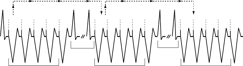
• If an arrhythmia crosses ventricular zones (accelerates or decelerates)
following therapy delivery and is redetected in a higher or lower ventricular
zone, a therapy of equal or greater strength than the previously delivered
therapy is selected from the detected zone and delivered (Figure 4-3 on
page 4-5 through Figure 4-10 on page 4-8). For shock therapy, the pulse
generator determines which shock to deliver prior to capacitor charging
based on the detected rate threshold. If during capacitor charging, the
tachyarrhythmia accelerates or decelerates from the initial detected rate,
the predetermined energy will still be delivered.
Redetection is performed after each therapy delivery to determine if further
therapy is required.
1 3 2 4 5 6 7
Zone ATP1 ATP2 QUICK
CONVERT ATP
Shock 1 Shock 2 Remaining Shocks
VF
VT
VT-1
On/Off
N/A
N/A
5 J
3 J
0.1 J
11 J
9 J
2 J
Burst Scan
Ramp Burst
max max max max max max
max max max max
max max max
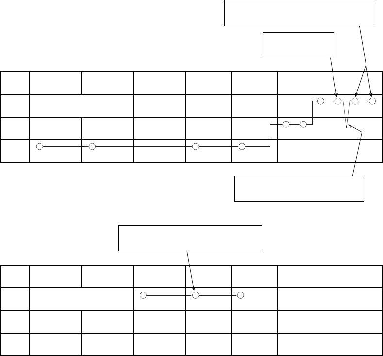
Figure 4-2. Therapy delivery progression, arrhythmia remains in same zone as initially detected
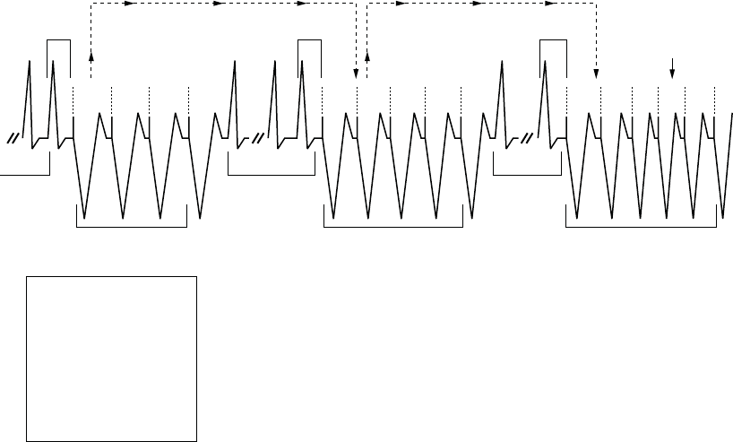
After each redetection cycle, therapy delivery progresses in the direction
indicated by the circled numbers (Figure 4-3 on page 4-5 through Figure 4-10
on page 4-8).
• Upward sloping lines indicate acceleration of the arrhythmia to a higher
ventricular zone
• Downward sloping lines indicate deceleration into a lower ventricular zone
- DRAFT -
TACHYARRHYTHMIA THERAPY
VENTRICULAR THERAPY 4-5
The lowest strength therapy is in the ATP columns; the therapy strengths
increase as you move to the right in the table.
NOTE: In the VT-1 zone of a 3-zone configuration or the VT zone of a
2-zone configuration, one or two ATP schemes may be programmed as the
only therapy, with all shocks in the lowest zone programmed to Off. If those
pacing schemes do not terminate an arrhythmia detected in the VT-1 zone, no
further therapy will be delivered in the episode unless the rate is redetected
in a higher zone.
1
3 6 7 8 9
4
5
2
Zone ATP1 ATP2 QUICK
CONVERT ATP
Shock 1 Shock 2 Remaining Shocks
VF
VT
VT-1
On/Off
N/A
N/A
2 J
3 J
0.1 J
11 J
9 J
2 J
Burst Off
Ramp Burst
max max max max max max
max max max max
max max max
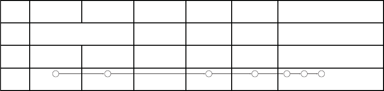
When the rhythm accelerates to the VF zone, Shock
2 in the VF zone is delivered since Shock 1 is a lower
energy level than Shock 1 in the VT zone.
ATP1 in the VT zone is delivered
because it is considered of equal
strength to VT-1 ATP2 therapy.
Figure 4-3. Therapy delivery progression, ATP1 in the VT zone and shock 2 in the VF zone
3
1 8 9
5
4
2
6
7
Zone ATP1 ATP2 QUICK
CONVERT ATP
Shock 1 Shock 2 Remaining Shocks
VF
VT
VT-1
On/Off
N/A
N/A
11 J
5 J
3 J
17 J
9 J
5 J
Burst Scan
Ramp Burst
max max max max max max
max max max max
max max max
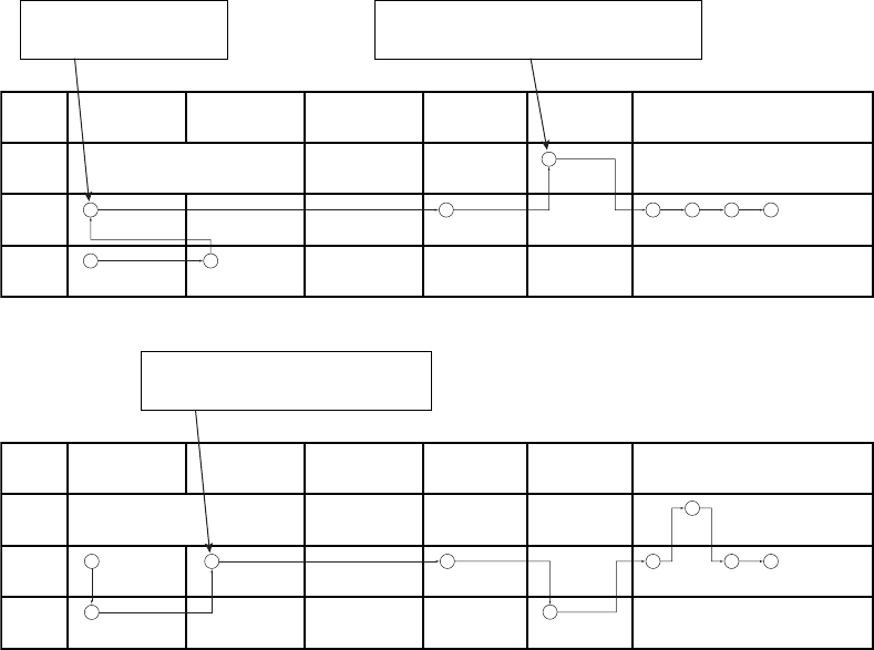
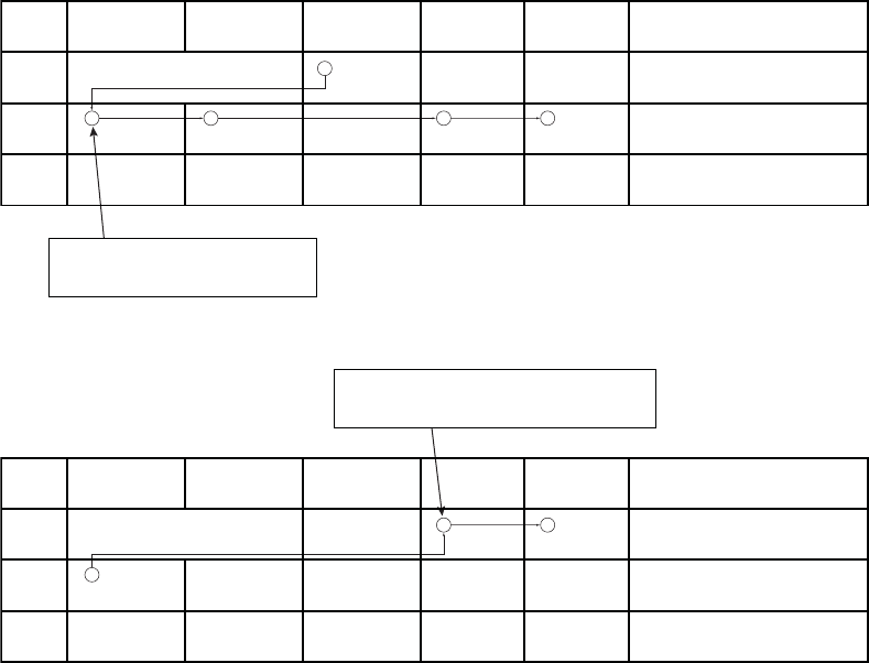
When the rhythm accelerates back to the VT
zone, ATP2 therapy is delivered because ATP1
has already been used during the episode.
Figure 4-4. Therapy delivery progression, ATP2 therapy
- DRAFT -
4-6 TACHYARRHYTHMIA THERAPY
VENTRICULAR THERAPY
3
5
2
1
4
6
8 9
7
Zone ATP1 ATP2 QUICK
CONVERT ATP
Shock 1 Shock 2 Remaining Shocks
VF
VT
VT-1
On/Off
N/A
N/A
5 J
1.1 J
3 J
11 J
9 J
5 J
Burst Scan
Ramp Burst
max max max max max max
max max max max
max max max
This is the third shock, since
two programmable shocks
have been delivered.
When the rhythm decelerates to the VT-1 zone, ATP2 of the VT-1 zone is
not delivered since a shock had already been delivered in the VT zone. So
the next higher strength therapy (Shock 1 of the VT-1 zone) is delivered.
Figure 4-5. Therapy delivery progression, shock 1 in the VT-1 zone
3
2
1 4
Zone ATP1 ATP2 QUICK
CONVERT ATP
Shock 1 Shock 2 Remaining Shocks
VF
VT
VT-1
On/Off
N/A
N/A
2 J
3 J
0.1 J
11 J
9 J
2 J
Burst Scan
Ramp Burst
max max max max max max
max max max max
Off Off Off
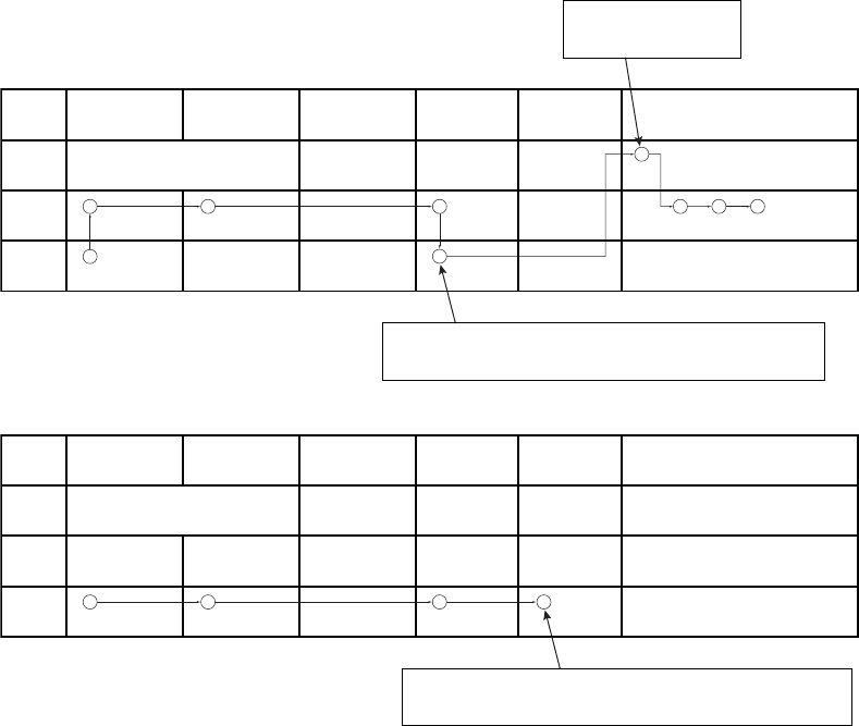
If the arrhythmia persists in the VT-1 zone after the second shock delivery,
no further shock therapy will be delivered unless the arrhythmia accelerates
to a higher zone since Shocks 3-5 are programmed Off in the VT-1 zone.
Figure 4-6. Therapy delivery progression, shocks 3 to 5 programmed to Off in the VT-1 zone
- DRAFT -
TACHYARRHYTHMIA THERAPY
VENTRICULAR THERAPY 4-7
5 6
7
3
2
1 4
10 8 9
The arrhythmia accelerated back to the VF zone, the
seventh shock is delivered. The arrhythmia persists in
the VF zone so the eighth (and final) shock is delivered.
A sixth shock is delivered
since the arrhythmia is in
the VF zone.
The arrhythmia decelerated to a lower zone, an
additional shock would not be delivered until the
arrhythmia accelerated back to the VF zone.
Zone ATP1 ATP2 QUICK
CONVERT ATP
Shock 1 Shock 2 Remaining Shocks
VF
VT
VT-1
On/Off
N/A
N/A
2 J
3 J
0.1 J
11 J
9 J
2 J
Burst Off
Ramp Burst
max max max max max max
max max max max
max max max
Figure 4-7. Therapy delivery progression, sixth shock delivered
1 3
2
Zone ATP1 ATP2
If reconfirmation indicates the arrhythmia persists
after delivery of QUICK CONVERT ATP, the device
immediately begins charging for Shock 1.
QUICK
CONVERT ATP
Shock 1 Shock 2 Remaining Shocks
VF
VT
VT-1
On
N/A
N/A
11 J
3 J
0.1 J
21 J
9 J
2 J
Burst Scan
Ramp Burst
max max max max max max
max max max max
max max max
Figure 4-8. Therapy delivery progression, QUICK CONVERT ATP and shock in the VF zone
- DRAFT -
4-8 TACHYARRHYTHMIA THERAPY
VENTRICULAR THERAPY
2
1
4 5
3
Zone ATP1 ATP2 QUICK
CONVERT ATP
Shock 1 Shock 2 Remaining Shocks
VF
VT
VT-1
On
N/A
N/A
2 J
3 J
0.1 J
11 J
9 J
2 J
Burst Scan
Ramp Burst
max max max max max max
max max max max
max max max
ATP1 in the VT zone is delivered because
it is considered of equal strength to QUICK
CONVERT ATP therapy.
Figure 4-9. Therapy delivery progression, QUICK CONVERT ATP decelerates the rhythm, ATP1 and shock
delivered in the VT zone
1
2 3
Zone ATP1 ATP2 QUICK
CONVERT ATP
Shock 1 Shock 2 Remaining Shocks
VF
VT
VT-1
On
N/A
N/A
11 J
3 J
0.1 J
21 J
9 J
2 J
Burst Scan
Ramp Burst
max max max max max max
max max max max
max max max
When the rhythm accelerates to the VF zone, Shock
1 is delivered because QUICK CONVERT ATP is
only available as the first therapy in an episode.
Figure 4-10. Therapy delivery progression, ATP1 in VT zone accelerates the rhythm, QUICK CONVERT ATP
isskippedinVFzone
Ventricular Redetection after Ventricular Therapy Delivery
After ventricular therapy delivery, the pulse generator uses redetection criteria
to evaluate the rhythm and determine whether more therapy is appropriate.
When redetection criteria are satisfied, the rules for therapy selection then
determine the type of therapy to deliver.
Ventricular Redetection after Ventricular ATP Therapy
Ventricular Redetection after ventricular ATP therapy determines if an
arrhythmia has been terminated.
As a ventricular ATP scheme is delivered, the pulse generator monitors the
cardiac rate after each burst and uses ventricular detection windows (looking
- DRAFT -
TACHYARRHYTHMIA THERAPY
VENTRICULAR THERAPY 4-9
for 8 of 10 fast intervals) and the Ventricular Redetection Duration to determine
ifthearrhythmiahasterminated.
The ATP scheme will continue with the next bursts in the sequence until any
one of the following conditions is satisfied:
• Redetection declares that the therapy has been successful (end-of-episode)
•Thespecified number of ATP bursts in the scheme has been delivered
• The ATP Time-out for the ventricular zone has expired
• The detected ventricular arrhythmia rate changes to a different ventricular
rate zone, whereby a different therapy is selected
• Shock If Unstable forces the device to skip the remaining ATP therapy
and initiate shock therapy
• A DIVERT THERAPY command is received from the PRM during delivery
of a burst of a scheme
• A magnet abort occurs during delivery of a scheme
• The temporary Tachy Mode has changed
• A commanded therapy is requested
• The episode ends due to reprogrammed Tachy Mode, reprogrammed
ventricular tachy parameters, or attempted induction method or lead test
NOTE: Aborting an ATP burst terminates the affected ATP scheme. If further
therapy is required, the next programmed therapy (either ATP or shocks) in
the prescription is initiated.
Ventricular Redetection after Ventricular Shock Therapy
Ventricular redetection after ventricular shock therapy determines if an
arrhythmia has been terminated.
As shock therapy is delivered, the pulse generator monitors the cardiac rate
after each shock and uses ventricular detection windows (looking for 8 of
10 fast intervals) and post-shock detection enhancements, if applicable, to
- DRAFT -
4-10 TACHYARRHYTHMIA THERAPY
ANTITACHYCARDIA PACING THERAPIES AND PARAMETERS
determine if the arrhythmia has been terminated. Shock therapy will continue
until one of the following conditions is satisfied:
• Redetection declares the therapy has been successful (end-of-episode)
• All available ventricular shocks have been delivered for an episode
• The rhythm is redetected in either the VT or VT-1 zone, the available
number of programmed shock(s) in those zones has been delivered and
the arrhythmia stays in one of these lower zones
If all available shocks have been delivered for an episode, no further therapy
is available until the pulse generator monitors a rate below the lowest rate
threshold for 30 seconds and end-of-episode is declared.
ANTITACHYCARDIA PACING THERAPIES AND PARAMETERS
Antitachycardia Pacing (ATP) therapy and parameters enable the pulse
generator to interrupt the following fast rhythms by delivering a series of
critically timed pacing pulses:
• Monomorphic ventricular tachycardia
• Supraventricular tachycardias
ATP Therapy is delivered when the last sensed event fulfills the programmed
detection criteria (Figure 4-11 on page 4-11).
An ATP scheme may be customized with the following parameters:
• Number of bursts delivered
• Number of pulses within each burst
• Coupling Interval
• Burst Cycle Length
• Minimum pacing interval
These parameters can be programmed to produce the following ATP therapy
schemes:
•Burst
•Ramp
•Scan
- DRAFT -
TACHYARRHYTHMIA THERAPY
ANTITACHYCARDIA PACING THERAPIES AND PARAMETERS 4-11
• Ramp/Scan
The ATP amplitude and pulse width are common to all schemes. They are
independently programmable from the normal pacing settings. The ATP
amplitude and pulse width share the same programmable value as the
post-therapy pacing settings.
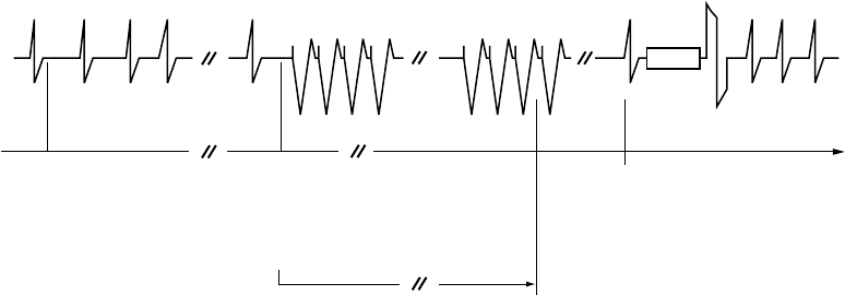
Coupling
Interval
Coupling
Interval
Burst Cycle Length
Burst 1 Burst 2
ATP Scheme
Redetection
ATP Pace Pulse
Burst Cycle Length
Figure 4-11. ATP therapy basic parameters are Coupling Interval, Burst Cycle Length, Number of Bursts,
and Number of Pulses within each burst.
Burst Parameters
A burst is a series of critically timed pacing pulses delivered by the pulse
generator during ATP therapy. By programming burst parameters, you can
optimize ATP therapy for the patient.
All ATP schemes have several parameters in common. In addition to
programming the type of scheme (Off, Burst, Ramp, Scan, Ramp/Scan), the
following burst parameters are programmable (Figure 4-12 on page 4-12):
• The Number of Bursts parameter determines the number of bursts used
in an ATP scheme and may be programmed independently for each ATP
scheme. Programming the parameter to Off will deactivate the ATP
scheme.
• The Initial Pulse Count parameter determines the number of pulses
delivered in the first burst of a scheme.
• The Pulse Increment parameter determines the number of pulses per burst
to be increased for each successive burst in the scheme.
- DRAFT -
4-12 TACHYARRHYTHMIA THERAPY
ANTITACHYCARDIA PACING THERAPIES AND PARAMETERS
• The Maximum Number of Pulses parameter determines the greatest
number of pulses used in an ATP burst and may be programmed
independently for each ATP scheme. After the maximum number of pulses
is reached in a burst, each additional burst remaining in the scheme
contains the programmed Maximum Number of Pulses. The parameter is
available only if the Pulse Increment is greater than zero.
Coupling
Interval
Redetect Redetect Redetect
Detection
Satisfied
Burst 1; Initial
pulse count at 3
Burst 2; Pulse count
incremented by 1
Burst 3; Pulse count
incremented by 1;
Maximum Number of
Pulses reached
Burst 4; (programmed
number); Pulse count
remaining at Maximum
Number of Pulses (5)
Number of Bursts = 4
Initial Pulse Count = 3
Pulse Increment = 1
Maximum Number of Pulses = 5
Figure 4-12. Interaction of Maximum Number of Pulses and Number of Bursts
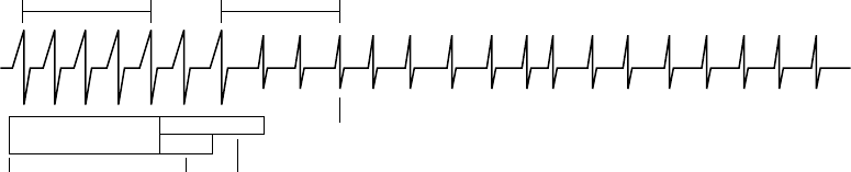
Coupling Interval and Coupling Interval Decrement
The Coupling Interval controls the timing of the firstpulseinaburst.Itdefines
thetimebetweenthelastsensedeventthatfulfills the detection criteria and
delivery of the first pulse in a burst.
The Coupling Interval is programmed independent from the Burst Cycle Length.
This allows aggressive ramps and scans to be used without compromising
capture of the first pacing pulse in a burst. The Coupling Interval can be
programmed as any of the following:
• Adaptive, with timing specified as percentages of the computed average
heart rate
•Afixed interval, with timing specified in absolute time (ms) independent of
the measured average rate
When programmed as adaptive, the Coupling Interval adjusts to the patient’s
rhythmbasedonafour-cycleaverage(Figure4-13onpage4-13). The
Coupling Interval Decrement may be programmed such that the Coupling
- DRAFT -
TACHYARRHYTHMIA THERAPY
ANTITACHYCARDIA PACING THERAPIES AND PARAMETERS 4-13
Interval decreases from one burst to the next within a multiple-burst scheme
(Figure4-14onpage4-13).
NOTE: You cannot program an ATP burst that lasts longer than 15 seconds.
The length of an adaptive burst is calculated based on the interval of the
ventricular zone in which the ATP is programmed, which means it is based
on worst-case timing.
Coupling Interval = 382 ms
4-Cycle Average = 420 ms
400
ms
410
ms
420
ms
450
ms
Coupling Interval (C.I.) = 91%
First C.I. is 420 x 91% = 382 ms
Second C.I. is 400 x 91% = 364 ms
The 4-cycle average is calculated on the four cycles prior to each tachycardia therapy delivery
only when no Decrement (Coupling Interval or Scan) is programmed.
Coupling Interval = 364 ms
4-Cycle Average = 400 ms
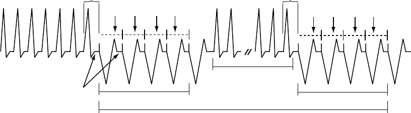
Figure 4-13. Adaptive Coupling Interval, Coupling Interval Decrement and Scan Decrement programmed to 0
Coupling Interval = 91%
C.I. Decrement = 10 ms
4-Cycle Average = 420 ms
Coupling
Interval =
382 ms Coupling Interval Decrement
(4-cycle average is not recalculated)
Coupling
Interval =
372 ms
Paced Pulses
Last sensed
R-wave that fulfills
redetection
Redetection
satisfied
Paced Pulses
Last sensed
R-wave that fulfills
detection
Detection satisfied
400
ms
410
ms
420
ms
450
ms
Figure 4-14. Coupling Interval Decrement
The following information should be taken into consideration when programming
the Coupling Interval and Coupling Interval Decrement:
• When the Coupling Interval Decrement is programmed to On, the
programmedATPschemeiscalledaScan
- DRAFT -
4-14 TACHYARRHYTHMIA THERAPY
ANTITACHYCARDIA PACING THERAPIES AND PARAMETERS
• When the Coupling Interval is programmed as adaptive, the Coupling
Interval will not re-adapt following redetection when the following are
programmed to On (greater than zero):
– Coupling Interval Decrement––the decrement value determines the
timing of the first pulse in subsequent bursts
– Scan Decrement––the decrement value determines the timing of the
second pulse in subsequent bursts
Burst Cycle Length (BCL)
The Burst Cycle Length controls the interval between pacing pulses after the
Coupling Interval.
This timing is controlled in the same fashion as the Coupling Interval: rate
adaptive to the sensed tachycardia or fixedtimespecified in ms.
NOTE: An adaptive BCL is affected in the same manner as an adaptive
Coupling Interval; the average cycle length is not continually recalculated for
subsequent bursts if the Scan Decrement or Coupling Interval Decrement are
programmed to On.
The following parameters may be programmed to decrement the burst cycle
length during an ATP scheme:
• Ramp Decrement controls the pulse timing within a given burst
• Scan Decrement controls the pulse timing between bursts
Minimum Interval
The Minimum Interval limits the Coupling Interval and the BCL in Burst, Ramp,
and Scan.
If the Coupling Interval reaches the limit, subsequent Coupling Intervals
will remain at the minimum value. Likewise, if the BCL reaches the limit,
subsequent BCLs will remain at the minimum value. The Coupling Interval and
BCL may reach the limit independently.
- DRAFT -
TACHYARRHYTHMIA THERAPY
ANTITACHYCARDIA PACING THERAPIES AND PARAMETERS 4-15
Burst Scheme
A Burst scheme is a sequence of critically timed pacing pulses intended to
interrupt a reentrant loop, usually delivered at a rate faster than the patient’s
tachycardia.
An ATP scheme is defined as a Burst (as indicated on the PRM screen) when
the timing of all pacing intervals within a burst is the same. The first BCL of
each Burst is determined by the programmed BCL. When the number of pulses
programmed in a Burst is greater than one, you can use the BCL to control the
timing between these paced pulses (Figure 4-15 on page 4-15).
Coupling
Interval
400
ms
410
ms
420
ms
450
ms
315
ms
BCL
315
ms
BCL
315
ms
BCL
315
ms
BCL
Coupling
Interval
300
ms
BCL
300
ms
BCL
300
ms
BCL
300
ms
BCL
Burst
4-Cycle Average = 400 ms
Burst
4-Cycle Average = 420 ms
BCL = 75%
420 ms x .75 = 315 ms
400 ms x .75 = 300 ms
The first BCL of each burst is calculated by multiplying the 4-cycle average prior to
delivery of the first pacing pulse of the burst by the BCL percentage.
Figure 4-15. Adaptive-rate Burst scheme
Ramp Scheme
A Ramp scheme is a burst in which each paced-to-paced interval within the
burst is shortened (decremented).
To program a Ramp scheme, program (in ms) the Ramp Decrement to specify
how much the paced-to-paced interval should be shortened, and the Scan
Decrement and Coupling Interval Decrement each to 0 ms. As each additional
paced pulse in a burst is delivered, its interval is shortened by the programmed
Ramp Decrement until either of the following occur:
• The last paced pulse of the burst is delivered
• The Minimum Interval is reached
- DRAFT -
4-16 TACHYARRHYTHMIA THERAPY
ANTITACHYCARDIA PACING THERAPIES AND PARAMETERS
If subsequent bursts are required, the programmed Ramp Decrement will be
applied based on the calculated BCL of that subsequent burst (Figure 4-16 on
page 4-16).
Burst Cycle Length = 75%
Ramp Decrement (R-R Within Burst) = 10 ms
Scan Decrement (R-R Between Bursts) = 0 ms
C.I. Decrement = 0 ms
Minimum Interval = 265 ms
300
ms
290
ms
280
ms
270
ms
4-Cycle Average
= 400 ms
Ramp Ramp
4-Cycle Average
= 380 ms
Readapt 75%
285
ms
275
ms
265
ms
265
ms
Minimum interval reached;
subsequent interval is not
decremented.
Redetect
Figure 4-16. Adaptive Ramp Scheme, Coupling Interval Decrement and Scan Decrement programmed to 0
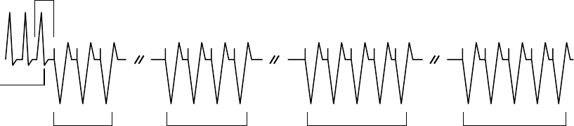
Scan Scheme
A Scan scheme is a burst in which the BCL of each burst in a scheme is
systematically shortened (decremented) between successive bursts.
YoucanprogramaScanschemebyprogrammingtheScanDecrementto
specify the BCL decrement to a value greater than 0 ms, while the Ramp
Decrement is programmed to 0 ms. The BCL of subsequent bursts is
determined by subtracting the Scan Decrement from the BCL of the previous
burst (Figure 4-17 on page 4-17).
- DRAFT -
TACHYARRHYTHMIA THERAPY
ANTITACHYCARDIA PACING THERAPIES AND PARAMETERS 4-17
Initial BCL is determined and then Scan
Decrement is applied on the next burst
BCL of previous Burst is determined and then Scan
Decrement is applied again on the next burst
300
ms
300
ms
300
ms
300
ms
290
ms
290
ms
290
ms
290
ms
280
ms
280
ms
280
ms
280
ms
Burst Cycle Length = 300 ms
Scan Decrement = 10 ms
Ramp Decrement = 0 ms
Coupling Interval Decrement = 0 ms
Scan Scan
Redetect Redetect
Scan
Figure 4-17. Scan scheme, nonadaptive BCL and Scan Decrement programmed on
Ramp/Scan Scheme
A Ramp/Scan scheme is a sequence of bursts. Each scheme contains a Ramp
Decrement and a Scan Decrement (Figure 4-18 on page 4-18).
- DRAFT -
4-18 TACHYARRHYTHMIA THERAPY
ANTITACHYCARDIA PACING THERAPIES AND PARAMETERS
290
ms
270
ms
280
ms
270
ms*
240
ms
250
ms
260
ms
240
ms
250
ms
220
ms
220
ms
230
ms
Minimum
interval
reached
4-Cycle
A
verage
= 370 ms
PARAMETER
Number of Bursts
Pulses per Burst:
Initial
Increment
Maximum
Coupling Interval
Decrement
Burst Cycle Length
Ramp Decrement
Scan Decrement
Minimum Interval
VALUE
3
4
1
6
81%
0 ms
78%
10 ms
20 ms
220 ms
* When a Scan Decrement is programmed to On, the Coupling Interval and
BCL, if programmed as a percentage, will not re-adapt following redetection.
Maximum Number of Pulses
reached (6) and Maximum
Number of Bursts reached (3)
Number of Pulses
incremented by 1
Ramp Burst Ramp/Scan Burst Ramp/Scan Burst
Redetect Redetect
C.I. 300 ms
Scan Scan
C.I. 300 ms* C.I. 300 ms*
Figure 4-18. Ramp/Scan scheme, interaction of ATP parameters
To program a Ramp/Scan scheme, both the Scan Decrement and Ramp
Decrement are programmed to values greater than 0 ms.
ATP Pulse Width and ATP Amplitude
The ATP Pulse Width is the duration of a pacing pulse. The ATP Amplitude is
the leading edge voltage of a pacing pulse.
TheprogrammedATPPulseWidthandATPAmplitudearesharedforallATP
schemes regardless of zone and position in a prescription. The ATP amplitude
and pulse width share the same programmable value as the post-therapy
pacing settings.
Ventricular ATP Time-out
The Ventricular ATP Time-out forces the pulse generator to skip over any
remaining ATP therapy in a ventricular zone to begin delivering ventricular
shock therapy programmed in the same zone. This parameter is effective
only for ventricular therapy delivery.
- DRAFT -
TACHYARRHYTHMIA THERAPY
ANTITACHYCARDIA PACING THERAPIES AND PARAMETERS 4-19
The ATP Time-out may be used in the VT or VT-1 zone as long as ATP therapy
is programmed to On. Timer values are independent, although VT-1 ATP
Time-out must be equal to or greater than the VT ATP Time-out.
The timer starts when the first burst is delivered and continues until any of the
following occur:
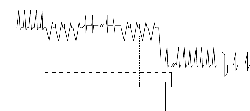
• The timer expires (Figure 4-19 on page 4-19)
• A ventricular shock is delivered
• The ventricular episode ends
The time-out is examined after each redetection sequence to determine if
further ATP bursts can be delivered. If the time-out has been reached or
exceeded, further ATP therapy will not be initiated during that ventricular
episode. The time-out will not terminate a burst in process.
Detection window met.
Start episode.
Start Duration.
Start stability analysis.
Duration expires.
Initiate ATP therapy.
Start ATP Time-out.
Redetection Duration expires.
Initiate shock therapy.
Charge
Redetect Redetect
ATP Time-out expires
30 s
Figure 4-19. ATP Time-out expiration
NOTE: Once a ventricular shock has been delivered during a ventricular
episode, ATP will no longer be invoked, irrespective of the time remaining
on the ATP Time-out timer.
The timer alone does not invoke therapy; the rate and duration criteria and
detection enhancements must still be satisfied in order for a shock therapy
to be delivered.
If three zones are programmed, you may program ATP Time-out settings in
each of the lower two ventricular zones (Figure 4-20 on page 4-20).
- DRAFT -
4-20 TACHYARRHYTHMIA THERAPY
ANTITACHYCARDIA PACING THERAPIES AND PARAMETERS
0 s 10 s 20 s 30 s 40 s
VF Zone
VT Zone
VT-1 Zone
VT Detection
window satisfied.
Duration starts.
Start episode. VT Detection met.
Therapy intitiated.
Start ATP Time-out.
AT Time-out expires
in VT zone.
VT-1
Time-out
expires.
VT-1 Detection met.
Initiate shock therapy.
Programmed therapy for lower zones:
VT-1 ATP Time-out = 40 s
VT ATP Time-out = 30 s
ATP is programmed in VT-1 and VT zones.
Redetection and
ATP bursts
ATP Time-out
ATP 1 ATP 1
Burst 1 Burst 5
Redetect
Charging
Rhythm changes to VT-1 zone
Figure 4-20. ATP Time-outs, 3-zone configuration
QUICK CONVERT ATP
QUICK CONVERT ATP provides you with an additional option to treat fast,
monomorphic VT that is detected in the VF zone.
When QUICK CONVERT ATP is programmed to On, the pulse generator
delivers one burst of ATP for an episode detected in the VF zone in an
attempt to avoid an otherwise scheduled charge and painful shock for a
pace-terminable fast VT.
When delivering QUICK CONVERT ATP therapy, the pulse generator delivers
one burst of ATP for an episode detected in the VF zone. This therapy consists
of 8 pacing pulses at 88% Coupling Interval and 88% BCL. It is delivered only
as the first therapy attempted in an episode and is followed by reconfirmation
(2 out of 3 intervals faster than the lowest rate threshold) prior to the shock
sequence.
In the event that QUICK CONVERT ATP was unsuccessful in converting the
rhythm and shock therapy is required, the feature’s algorithm minimizes the
delay to begin charging. QUICK CONVERT ATP is not applied to any rhythm
above a maximum rate of 250 bpm.
- DRAFT -
TACHYARRHYTHMIA THERAPY
VENTRICULAR SHOCK THERAPY AND PARAMETERS 4-21
VENTRICULAR SHOCK THERAPY AND PARAMETERS
The pulse generator delivers shocks synchronous to a sensed event. The
shock vector, energy level, and polarity of the shocks are programmable.
Ventricular Shock Vector
The programmed Ventricular Shock Vector indicates the vector of energy
delivery for ventricular shock therapy.
The following programmable configurations are available:
• RV Coil to RA Coil and Can––this vector is also known as the V-TRIAD
vector. It uses the metallic housing of the pulse generator as an active
electrode (“hot can”) combined with the ENDOTAK two-electrode
defibrillation lead. Energy is sent via a dual-current pathway from the distal
shocking electrode to the proximal electrode and to the pulse generator
case.
• RV Coil to Can––this vector uses the metallic housing of the pulse
generator as an active electrode (“hot can”). Energy is sent from the distal
shocking electrode to the pulse generator case. This configuration should
be selected when using a single-coil lead.
• RV Coil to RA Coil––this vector removes the pulse generator case as
an active electrode and is also known as a “cold can” vector. Energy is
sent from the distal shocking electrode to the proximal electrode. This
vector should never be used with a single-coil lead, as a shock will not
be delivered.
Ventricular Shock Energy
Ventricular shock energy determines the strength of shock therapy delivered
by the pulse generator.
Shock output remains constant over the lifetime of the pulse generator,
regardless of changes in lead impedance or battery voltage. The constant
output is accomplished by varying pulse width to adjust to changes in lead
impedance.
The first two shocks in each ventricular zone can be programmed to optimize
charge time, longevity, and safety margins. The remaining shock energies in
each zone are nonprogrammable at the maximum-energy value.
- DRAFT -

4-22 TACHYARRHYTHMIA THERAPY
VENTRICULAR SHOCK THERAPY AND PARAMETERS
Charge Time
Charge time is the time the pulse generator requires to charge for delivery of
the programmed shock energy.
Charge time is dependent on the following:
• Programmed output energy level
• Battery condition
• Condition of the energy storage capacitors
Charge times increase as the pulse generator is programmed to higher energy
output levels and as the battery depletes (Table 4-1 on page 4-22).
Capacitor deformation can occur during inactive periods and may result in a
slightly longer charge time. To reduce the impact of capacitor deformation on
charge time, the capacitors are automatically reformed.
Table 4-1. Typical charge time required at 37 degrees C at BOL
Energy Stored (J)aEnergy Delivered
(J)b
Charge Time
(seconds)c
11.0 10.0 1.9
17.0 15.0 2.9
26.0 22.0 4.7
41.0d35.0 8.4
a. Values indicate the energy level stored on the capacitors and correspond to the value programmed for shock energy parameters.
b. The energy delivered indicates the shock energy level delivered through the shocking electrodes.
c. Charge times shown are at BOL after capacitor re-formation.
d. HE.
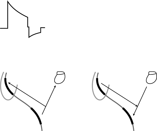
Waveform Polarity
Waveform polarity reflects the relationship between the leading edge voltages
on the defibrillating output electrodes. All shocks will be delivered using a
biphasic waveform (Figure 4-21 on page 4-23).
The selection of the shock polarity applies to all shocks delivered by the device.
If the preceding shocks in a zone are unsuccessful, the last shock of that zone
will be automatically delivered at an inverted polarity to the previous shock
(initial or reversed) (Figure 4-22 on page 4-23).
- DRAFT -
TACHYARRHYTHMIA THERAPY
VENTRICULAR SHOCK THERAPY AND PARAMETERS 4-23
CAUTION: For IS-1/DF-1 leads, never change the shock waveform
polarity by physically switching the lead anodes and cathodes in the pulse
generator header—use the programmable Polarity feature. Device damage
or nonconversion of the arrhythmia post-operatively may result if the polarity
is switched physically.
Biphasic
V1
V2
PW1 PW2
V3
V4
PW = Pulse Width
PW2 = PW1 x 0.66
V2 = V3
Figure 4-21. Biphasic waveform
+
–
+
–
+
–
Initial polarity Reverse polarity
Figure 4-22. Polarity of shock delivery
Committed Shock/Reconfirmation of the Ventricular Arrhythmia
Committed Shock/Reconfirmation refers to the monitoring performed by the
pulse generator before delivery of a ventricular shock.
If the patient is subject to non-sustained arrhythmias, reconfirmation may be
desirable in order to prevent delivery of unnecessary shocks to the patient.
- DRAFT -
4-24 TACHYARRHYTHMIA THERAPY
VENTRICULAR SHOCK THERAPY AND PARAMETERS
The device monitors tachyarrhythmias during and immediately following
capacitor charging. During this time, it checks for the spontaneous conversion
of the tachyarrhythmia and determines whether ventricular shock therapy
should be delivered; it does not affect therapy selection.
Ventricular shock therapy can be programmed as committed or non-committed.
If the Committed Shock feature is programmed to On, the shock is delivered
synchronously with the first sensed R-wave following a 500-ms delay after the
capacitors are charged, whether the arrhythmia is sustained or not (Figure 4-23
on page 4-24). The 500-ms delay allows a minimum time for a divert command
to be issued from the PRM, if desired. If there is no sensed R-wave detected
within 2 seconds following the end of charging, the ventricular shock is
delivered asynchronously at the end of the 2-second interval.
Shock
2 3 4 5 6 7 8 9 10 11 121
FF FF F F FFF F
Shock is committed.
Synchronize with R-wave and deliver shock.
Duration complete.
Start charging.
Refractory
period
Divert window
Charging 500 ms
135 ms
Redetection starts. Detection window satisfied.
Post-Shock Duration starts.
Number of intervals
(F = Fast)
Figure 4-23. Committed Shock is programmed to On, Reconfirmation is Off
NOTE: There is a forced 135-ms refractory period following the end of
charging; events that occur during the first 135 ms of the 500-ms delay are
ignored.
If the Committed Shock feature is programmed to Off, Reconfirmation consists
of the following steps:
1. During capacitor charging, the pulse generator continues to sense the
arrhythmia. Sensed and paced beats are evaluated. If 5 slow beats (sensed
or paced) are counted in a 10-beat detection window (or 4 consecutive
slow beats after an unsuccessful QUICK CONVERT ATP attempt), the
pulse generator stops charging and considers this a Diverted-Reconfirm.
2. If 5 of 10 beats are not detected as slow (or less than 4 consecutive slow
beats after an unsuccessful QUICK CONVERT ATP attempt) and charging
completes, post-charge reconfirmation is performed after charging ends.
- DRAFT -
TACHYARRHYTHMIA THERAPY
VENTRICULAR SHOCK THERAPY AND PARAMETERS 4-25
After the post-charge refractory and the first sensed event, the pulse
generator measures up to 3 intervals following charging and compares
them to the lowest rate threshold.
• If 2 of the 3 intervals following charging are faster than the lowest rate
threshold, the shock will be delivered synchronously with the second
fast event.
• If 2 of the 3 intervals following charging are slower than the lowest
rate threshold, the shock will not be delivered. If no beats are sensed,
pacing will begin at the programmed LRL following the 2-second
no-sense period. If a shock is not delivered, or if pacing pulses are
delivered, this is also considered a Diverted-Reconfirm.
If a shock is required after redetection, the charge time for the shock may
be short.
The reconfirmation algorithm will not allow two consecutive Diverted-Reconfirm
cycles. If the arrhythmia is detected after a Diverted-Reconfirm, the next shock
in the episode is delivered as if Committed Shock were programmed to On.
Once a shock has been delivered, the reconfirmation algorithm can be applied
again (Figure 4-24 on page 4-25).
23 4 56 7 81
23 4 51231
Intervals are measured and compared to the lowest Rate threshold. If 2 of 3 are slow,
the shock will not be delivered. If 2 of 3 are fast, the shock will be delivered.
Reconfirmation determines arrhythmia
is no longer present. Shock is not
delivered. If no beats are sensed,
pacing will start.
Duration complete.
Start charging.
Refractory
period
Divert
window
Intervals are measured
during charging.
Charging 500 ms
135 ms
Figure 4-24. Committed Shock is programmed to Off, reconfirmation is On
- DRAFT -
4-26 TACHYARRHYTHMIA THERAPY
VENTRICULAR SHOCK THERAPY AND PARAMETERS
- DRAFT -
- DRAFT -

Boston Scientific
4100 Hamline Avenue North
St. Paul, MN 55112–5798 USA
www.bostonscientific.com
1.800.CARDIAC (227.3422)
+1.651.582.4000
© 2007 Boston Scientificoritsaffiliates
All rights reserved.
357400-001 US 12/07
FCC ID: ESCCRMN11906
IC: 4794A-CRMN1196
Part 1 of 2
*357400-001*
- DRAFT -

SYSTEM GUIDE
COGNIS™100-D
CARDIAC RESYNCHRONIZATION THERAPY
HIGH ENERGY DEFIBRILLATOR
REF N118, N119
CAUTION: Federal law
restricts this device to sale by
or on the order of a physician
trained or experienced in
device implant and follow-up
procedures. Part 2 of 2
- DRAFT -
- DRAFT -

5-1
PACING THERAPIES
CHAPTER 5
This chapter contains the following topics:
• "Device Programming Recommendations" on page 5-2
• "Maintaining CRT" on page 5-4
• "Pacing Therapies" on page 5-6
• "Basic Parameters" on page 5-7
• "Post-Therapy Pacing" on page 5-17
• "Temporary Pacing" on page 5-18
• "Sensors and Trending" on page 5-19
• "Atrial Tachy Response" on page 5-27
• "Rate Enhancements" on page 5-35
• "Lead Configuration" on page 5-42
• "AV Delay" on page 5-46
• "Refractory" on page 5-52
• "Noise Response" on page 5-60
• "Ventricular Tachy Sensing Interactions" on page 5-62
- DRAFT -
5-2 PACING THERAPIES
DEVICE PROGRAMMING RECOMMENDATIONS
DEVICE PROGRAMMING RECOMMENDATIONS
It is important to program device parameters to the appropriate settings to
ensure optimal CRT delivery. Please consider the following guidelines in
conjunction with the patient’s specific condition and therapy needs.
CAUTION: This device is intended to provide biventricular pacing therapy.
Programming the device to provide RV-only pacing, or programming the RV
pace amplitude below the pacing threshold (resulting in LV-only pacing), is not
intended for the treatment of heart failure. The clinical effects of LV-only or
RV-only pacing for the treatment of heart failure have not been established.
Pacing mode––Program a dual-chamber tracking mode (VDD or DDD).
Adaptive-rate pacing modes are intended for patients who exhibit chronotropic
incompetence and who would benefit by increased pacing rates concurrent
with physical activity ("Brady Mode" on page 5-7).
Pacing chamber––Program to BiV (nominal) unless medical discretion dictates
the selection of a different pacing chamber ("Ventricular Pacing Chamber" on
page 5-14).
BiV Trigger––Program to On unless there is a medical contraindication.
LRL––Program below a sinus rate normally reached while still providing an
appropriate rate for bradycardia support ("Lower Rate Limit (LRL)" on page
5-10).
MTR––Program high enough to ensure 1:1 AV synchrony. A MTR at 130 ppm
is recommended unless medical discretion dictates otherwise ("Maximum
Tracking Rate (MTR)" on page 5-11).
Pacing output––Program for a minimum 2x voltage safety margin for each
ventricular chamber based on the capture thresholds ("Pace Threshold Test"
on page 6-8).
Paced AV Delay––The Paced AV Delay setting should be individualized for
each patient to ensure consistent CRT delivery. Several methods are available
to determine the Paced AV Delay setting, including:
• Intrinsic QRS duration assessment
• Echocardiogram
• Pulse pressure monitoring
- DRAFT -
PACING THERAPIES
DEVICE PROGRAMMING RECOMMENDATIONS 5-3
Since optimizing the Paced AV Delay can significantly influence CRT
effectiveness, consider using methods that demonstrate the hemodynamic
impact of different Paced AV Delay settings, such as echocardiography or pulse
pressure monitoring.
Atrial pacing may prolong the interatrial delay; therefore, it may be necessary
to program different Paced AV Delay settings to optimize CRT during normal
sinus rhythm and atrial pacing.
Sensed AV Delay––Sensed AV Delay is used to achieve a shorter AV Delay
following sensed atrial events while the longer, programmed Paced AV Delay is
used following paced atrial events. When programmed to the DDD(R) mode, it
is recommended that the patient be tested to determine the optimal Sensed AV
Delay during atrial sensing and pacing.
Dynamic AV Delay––Dynamic AV Delay is set automatically based on the
following ("Paced AV Delay" on page 5-46):
• If the minimum and maximum Paced AV Delays are equal, then AV Delay
is fixed.
• If the minimum Paced AV Delay is less than the maximum, then AV Delay
is set to Dynamic.
PVARP––Program PVARP to 280 ms. For heart failure patients with intact AV
conduction, a long intrinsic intracardiac AV interval and a long programmed
PVARP can cause a loss of atrial tracking below the MTR, resulting in a loss of
BiV stimulation (CRT). If you believe a loss of atrial tracking below the MTR
is occurring, program Tracking Preference to On (nominal) ("A-Refractory
(PVARP)" on page 5-52).
PVARP after PVC––Program PVARP after PVC to 400 ms (nominal) to
potentially reduce the number of PMTs at high rates. The occurrence of PMTs
may also be due to other factors ("PVARP after PVC" on page 5-54).
ATR––If ATR is used, Entry and Exit Counts should be programmed to ensure
appropriate and timely mode switching ("Atrial Tachy Response" on page 5-27).
Note that VRR and BiV Trigger have the potential to increase CRT delivery
during atrial tachyarrhythmias. BiV Trigger should be programmed to On, and
VRR should be programmed to On at the maximum setting to increase the
percent of ventricular pacing and maximize consistent CRT delivery during
conducted atrial tachyarrhythmias.
- DRAFT -
5-4 PACING THERAPIES
MAINTAINING CRT
PMT Termination––Program to On (nominal) to prevent PMTs at high rates
("PMT Termination" on page 5-35).
LVPP––Program to 400 ms (nominal) to prevent the device from pacing in the
LV vulnerable period ("Left Ventricular Protection Period (LVPP)" on page 5-55).
Tracking Preference––Program to On (nominal) to support CRT delivery for
atrial rates below, but near, the MTR. Use this feature when PVARP and the
patient’s intrinsic intracardiac AV interval are longer than the programmed MTR
interval ("Tracking Preference" on page 5-36).
LV lead configuration––Program in accordance with the number of electrodes
on the LV lead ("Left Ventricular Electrode Configuration" on page 5-42).
MAINTAINING CRT
Certain conditions may cause the temporary loss of CRT or AV synchrony
due to Wenckebach-like behavior, and heart failure patients may become
symptomatic if CRT is compromised. Please consider the following when you
are programming the device.
MTR
Rapid atrial rates with a fast ventricular response above MTR can cause:
• Temporary inhibition of CRT if AV conduction is intact
• Wenckebach-like behavior if second- or third-degree AV block is present
CRT delivery and programmed AV synchrony return when normal sinus rates
are restored.
MTR should be programmed sufficiently high to maintain CRT at fast atrial
rates. In addition, please consider the following for maintaining CRT:
• Rate Smoothing may be used to prevent sudden drops in rate
• VRR may help promote CRT by increasing the percent of ventricular pacing
during conducted atrial arrhythmias
• SVTs may require medical management to preserve CRT as well as protect
the patient from the potential hemodynamic compromise associated with
fast rates
- DRAFT -
PACING THERAPIES
MAINTAINING CRT 5-5
• Medical management of fast atrial rates can maximize the amount of time
that the patient remains below MTR and help ensure consistent CRT
delivery
NOTE: If a patient has slow VT, the ability to program higher MTR values is
limited by the lower rate threshold of the lowest tachyarrhythmia zone.
For CRT delivery at heart rates that correspond to the slow VT rate, consider
managing the slow VT by alternate means such as antiarrhythmic drugs or
catheter ablation to ensure consistent CRT.
AFR
AFR may delay or inhibit an atrial paced event and prevent pacing into the atrial
vulnerable period and to provide immediate fallback for atrial rates higher than
the AFR programmable rate. This changes the AV Delay and may impact CRT
effectiveness if the AFR rate is programmed slower than the patient’s sinus rate.
Rate Smoothing
When Rate Smoothing Up is programmed to On, CRT is compromised during
episodes of atrial rate increases exceeding the programmed value. For patients
with AV block, this occurs because Rate Smoothing Up prolongs AV Delay
from the optimal setting (controls the biventricular pacing rate while the atrial
rate increases).
Features that Switch to VVI or VVI-like Behavior
VTR/ATR may result in Wenckebach-like behavior or the temporary loss
of CRT. CRT delivery with programmed AV synchrony will return when the
SVT/VT/VF event is resolved and a normal sinus rhythm is restored.
For patients programmed to VDD with sinus rates below LRL, CRT will not be
synchronized with atrial events and loss of AV synchrony will result. You can
either program a lower LRL or enable a pacing mode that provides atrial pacing
with synchronous ventricular pacing [e.g., DDD(R)], as medically appropriate.
STAT PACE delivers CRT in VVI mode with a loss of AV synchrony. The
permanent, programmed settings resume when the pulse generator is
programmed out of STAT PACE.
- DRAFT -
5-6 PACING THERAPIES
PACING THERAPIES
PACING THERAPIES
CRT-Ds provide both atrial and biventricular normal and post-therapy
bradycardia pacing, including adaptive-rate modes.
The bradycardia pacing function is independent of the tachycardia detection
and therapy functions of the device, with the exception of interval-to-interval
sensing.
The pulse generator provides the following types of therapies:
CRT
• When the patient’s intrinsic atrial rate is below the MTR and the
programmed AV Delay is less than the intrinsic intracardiac AV interval, the
device delivers pacing pulses to the ventricles at the programmed settings
in order to synchronize ventricular contractions
• Independent programmability of the RV and LV leads allows therapeutic
flexibility for restoring the mechanical coordination
CAUTION: To ensure a high percentage of biventricular pacing, the
programmed AV Delay setting must be less than the patient’s intrinsic PR
interval.
Normal Bradycardia Pacing
• If the intrinsic heart rate falls below the programmed pacing rate (i.e., LRL),
the device delivers pacing pulses at the programmed settings
• Sensor-based rate modulation allows the pulse generator to adapt the
pacing rate to the patient’s changing activity levels
Post-Therapy Pacing—alternative bradycardia pacing therapy may be
delivered for a programmed period to ensure capture after delivery of a shock.
Additional Options
•Temporary Bradycardia Pacing––allows the clinician to examine
alternate therapies while maintaining the previously programmed Normal
pacing settings in the pulse generator memory.
- DRAFT -
PACING THERAPIES
BASIC PARAMETERS 5-7
•STAT PACE––initiates emergency ventricular pacing at high output settings
when commanded via the PRM using telemetry communication.
BASIC PARAMETERS
By programming device parameters, the pulse generator provides CRT for the
intent of providing mechanical synchronization. The programming options used
for CRT include those used for bradycardia pacing therapy.
LV stimulation is delivered using a Guidant coronary venous lead. The device
uses bipolar atrial pacing and sensing to coordinate AV contractions with CRT.
Normal Settings include the following:
• Pacing parameters, which are independently programmable from
post-therapy and temporary pacing parameters
NOTE: These parameters are also used for CRT.
• Pacing and Sensing
• Leads
• Sensors and Trending
Post-Therapy Settings include the following:
• Pacing parameters, which are independently programmable from normal
and temporary pacing parameters
• Post-ventricular shock
Brady Mode
Brady modes provide you with programmable options to help individualize
patient therapy.
This pulse generator includes the pacing modes identified in the Programmable
Options appendix.
CRT Modes
The objective of CRT is to deliver continuous pacing to the ventricles. CRT can
only be delivered in modes that provide ventricular pacing.
- DRAFT -
5-8 PACING THERAPIES
BASIC PARAMETERS
The maximal CRT benefit can be achieved when biventricular stimulation
is delivered. Atrial pacing and adaptive-rate modes may be appropriate for
patients who also experience bradycardia.
WARNING: Do not use atrial-only modes in patients with heart failure
because such modes do not provide CRT.
NOTE: The safety and effectiveness of CRT was evaluated in clinical studies
using the VDD mode. Use medical discretion when programming the pulse
generator to pacing modes other than VDD.
NOTE: Atrial pacing may prolong interatrial conduction, desynchronizing
right and left atrial contractions. The effect of atrial pacing on CRT has not
been studied.
DDD and DDDR
• Could be appropriate for heart failure patients with sinus bradycardia
since DDD(R) can provide atrial-synchronous biventricular pacing at rates
above the LRL and AV-sequential biventricular pacing at the LRL or
sensor-indicated rate—DDDR
• DDD mode may be preferred over VDD mode for patients with sinus
bradycardia or atrial rates below the LRL to preserve AV synchrony with
CRT delivery
DDI and DDIR
• May not be appropriate for heart failure patients with normal sinus activity
• Could be appropriate for heart failure patients who have no underlying
intrinsic sinus rhythm but might experience episodes of atrial
tachyarrhythmias such as brady-tachy syndrome
• Provide AV-sequential biventricular pacing only at the LRL or
sensor-indicated rate, DDIR, in the absence of sinus activity
• During periods of intrinsic atrial activity above the LRL,
non-atrial-synchronous biventricular pacing is delivered at the LRL or
sensor-indicated rate
- DRAFT -
PACING THERAPIES
BASIC PARAMETERS 5-9
VDD
• VDD is appropriate for heart failure patients with normal sinus activity, since
VDD delivers atrial-synchronous biventricular pacing but no atrial pacing
• Consider programming a low LRL for bradycardia support since AV
asynchrony is likely to occur during LRL ventricular pacing
• If frequent pacing at the LRL is anticipated or observed, consider
programming a DDD(R) mode to maintain AV synchrony during LRL pacing
VDDR
• VDDR may not be appropriate for heart failure patients with normal sinus
activity due to the increased potential for loss of AV synchrony
• While this mode can provide atrial-synchronous biventricular pacing during
normal sinus activity, sensor-driven ventricular pacing will result in the loss
of AV synchrony if the sensor-indicated rate exceeds the sinus rate
VVI and VVIR
• May be detrimental for heart failure patients with normal sinus activity
• Could be appropriate for heart failure patients with chronic atrial
tachyarrhythmias or during episodes of atrial tachyarrhythmia since they
provide biventricular pacing at the LRL or sensor-indicated rate—VVI(R)
• If patients have AV conduction during atrial tachyarrhythmias that results in
inhibition of biventricular pacing (loss of CRT), consider programming an
elevated LRL in an attempt to increase the delivery of biventricular pacing
and/or to VVI(R), if not already programmed
Dual-Chamber Modes
Do not use DDD(R) and VDD(R) modes in the following situations:
• In patients with chronic refractory atrial tachyarrhythmias (atrial fibrillation
or flutter), which may trigger ventricular pacing
• In the presence of slow retrograde conduction that induces PMT, which
cannot be controlled by reprogramming selective parameter values
- DRAFT -
5-10 PACING THERAPIES
BASIC PARAMETERS
Atrial Pacing Modes
In DDD(R), DDI(R), and AAI(R) modes, atrial pacing may be ineffective in
the presence of chronic atrial fibrillation or flutter or in an atrium that does
not respond to electrical stimulation. In addition, the presence of clinically
significant conduction disturbances may contraindicate the use of atrial pacing.
WARNING: Do not use atrial tracking modes in patients with chronic refractory
atrial tachyarrhythmias. Tracking of atrial arrhythmias could result in VT or VF.
NOTE: Refer to "Use of Atrial Information" on page 3-5 for additional
information about device performance when the atrial lead is programmed to
Off.
If you have any questions regarding the individualization of patient therapy,
contact your sales representative or call Technical Services at the number
shown on the back cover of this manual.
Lower Rate Limit (LRL)
LRL is the number of pulses per minute at which the pulse generator paces in
the absence of sensed intrinsic activity.
The following interactive limits are effective when programming the LRL.
Exercise caution when programming permanent pacing rates below 50 ppm or
above 100 ppm.
•LRLmustbelessthan:
–MPR
–MSR
–MTR
• LRL must be at least 15 ppm less than the lowest tachy zone threshold
• The greater of the following values must be at least 10 ppm less than the
lowest tachy zone threshold:
–MPR
–MSR
–MTR
- DRAFT -
PACING THERAPIES
BASIC PARAMETERS 5-11
In VDD mode, biventricular pacing at the LRL may result in the loss
of AV synchrony, which will diminish the benefitofCRT.Topromote
atrial-synchronous biventricular pacing and minimize the loss of AV synchrony,
consider programming the LRL below a sinus rate normally reached while still
providing an appropriate rate for bradycardia support.
In VVI mode, biventricular pacing only occurs when the intrinsic ventricular
rate is below the LRL. To increase the likelihood of delivering biventricular
pacing when the patient has intrinsic AV conduction, consider programming an
elevated LRL and/or consider an adaptive-rate pacing mode (VVIR).
Runaway Protection
Runaway protection is designed to prevent pacing rate accelerations for most
single-component failures. This feature is not programmable and operates
independently from the pulse generator’s main pacing circuitry.
The basic pulse period is equal to the pacing rate and the pulse interval (without
hysteresis). Runaway protection prevents the pacing rate from increasing
above 205 ppm.
NOTE: Magnet application does not affect the pacing rate (pulse interval).
NOTE: Runaway protection is not an absolute assurance that runaways will
not occur.
During PES, Manual Burst pacing, and ATP, runaway protection is temporarily
suspended to allow for high-rate pacing.
Maximum Tracking Rate (MTR)
TheMTRisthemaximumrateatwhichthepacedventricularratetracks1:1
with nonrefractory sensed atrial events. MTR applies to atrial synchronous
pacing modes, namely DDD(R) and VDD(R).
The following are considerations for programming the MTR:
• Interactive limits ("Lower Rate Limit (LRL)" on page 5-10).
- DRAFT -
5-12 PACING THERAPIES
BASIC PARAMETERS
• For heart failure patients with normal AV conduction, biventricular
stimulation (CRT) may not be delivered when the atrial rate exceeds
the MTR. This can occur if the AV Delay lengthens beyond the patient’s
intrinsic intracardiac AV interval and AV conduction occurs, which inhibits
ventricular pacing. In both situations (AV block and AV conduction) CRT is
compromised when the atrial rate exceeds the MTR, either because of the
suboptimal, prolonged AV Delay or a loss of biventricular pacing, or both.
• If the patient’s normal atrial rate exceeds the MTR, consider programming
a higher MTR to ensure 1:1 atrial synchronous, biventricular pacing at
the programmed AV Delay. If reprogramming a higher MTR is limited by
the current TARP (AV Delay + PVARP = TARP), attempt to shorten the
PVARP before shortening the AV Delay in order to avoid a suboptimal AV
Delay for CRT.
• When the sensed atrial rate is between the programmed LRL and MTR, 1:1
ventricular pacing will occur in the absence of a sensed ventricular event
within the programmed AV Delay. If the sensed atrial rate exceeds the MTR,
the pulse generator might begin a Wenckebach-like behavior to prevent
the paced ventricular rate from exceeding the MTR. This Wenckebach-like
behavior is characterized by a progressive lengthening of the AV delay
until an occasional P-wave is not tracked because it falls into the PVARP.
This results in an occasional loss of 1:1 tracking as the pulse generator
synchronizes its paced ventricular rate to the next sensed P-wave. Should
the sensed atrial rate continue to increase further above the MTR, the ratio
of sensed atrial events to sequentially paced ventricular events becomes
lower until, eventually, 2:1 block results (e.g., 5:4, 4:3, 3:2, and finally 2:1).
• The PRM will not allow you to program an MTR interval shorter than TARP
(AV Delay + PVARP = TARP). If TARP is less than the interval of the
programmed MTR, then the pulse generator’s Wenckebach-like behavior
limits the ventricular pacing rate to the MTR.
• Rapid changes in the paced ventricular rate (e.g., Wenckebach-like, 2:1
block) caused by sensed atrial rates above the MTR may be dampened or
eliminated by the implementation of any of the following:
–AFR
–ATR
– Rate Smoothing parameters and sensor input
–VRR
- DRAFT -
PACING THERAPIES
BASIC PARAMETERS 5-13
Maximum Sensor Rate (MSR)
MSR is the maximum pacing rate allowed as a result of sensor control from
accelerometer input.
The following considerations are important when programming MSR:
• Patient’s condition, age, and general health:
– Adaptive-rate pacing at higher rates may be inappropriate for patients
who experience angina or other symptoms of myocardial ischemia at
these higher rates
– An appropriate MSR should be selected based on an assessment of
the highest pacing rate that the patient can tolerate well
• Interactive limits ("Lower Rate Limit (LRL)" on page 5-10)
NOTE: If the pulse generator is operating in DDD(R) or VDD(R) mode, the
MSR and MTR may be programmed independently to different values.
MSR is independently programmable at, above, or below the MTR. If the MSR
settingishigherthantheMTR,apacingrateabovetheMTRmayoccurin
the presence of high activity levels.
Pacing above the MSR can only occur in response to sensed intrinsic atrial
activity.
With 1:1 conduction, the pulse generator maintains the A–A pacing rate by
extending the V–V pacing rate. This extension is determined by the degree of
difference between the AV Delay and the intrinsic ventricular conduction—often
referred to as modified atrial-based timing (Figure 5-1 on page 5-14).
- DRAFT -
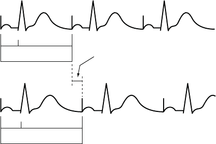
5-14 PACING THERAPIES
BASIC PARAMETERS
Pacing without modified
right ventricular timing
Pacing with modified
right ventricular timing
150
200 ms
AV VA
AV + VA Forced extension of
the V-A interval
150
200 ms
AV VA
AV + VA + extension
MSR 400 ms (150 min-1 [ppm])
AV 150 ms (conducted event)
V-A 200 ms
Pacing interval = AV + VA = 350 ms
MSR 400 ms (150 min-1 [ppm])
AV 150 ms (conducted event)
VA 200 ms
V-A Ext. 50 ms
Pacing interval = AV + VA + VA extension = 400 ms
The pulse generator’s timing algorithm provides effective pacing at the MSR with intrinsic ventricular conduction.
Extending the VA interval prevents the A pace from exceeding the MSR at high rates.
Figure 5-1. VA interval extension and MSR
Ventricular Pacing Chamber
With the ventricular Pacing Chamber option, you can choose which chamber(s)
will receive pacing pulses.
The following options are available:
•RV
• BiV (both RV and LV)—when selected, LV Offset becomes available
CAUTION: This device is intended to provide biventricular pacing therapy.
Programming the device to provide RV-only pacing, or programming the RV
pace amplitude below the pacing threshold (resulting in LV-only pacing), is not
intended for the treatment of heart failure. The clinical effects of LV-only or
RV-only pacing for the treatment of heart failure have not been established.
LV Offset
LV Offset provides programming flexibility by allowing you to adjust the delay
between delivery of the LV and RV pacing pulses.
- DRAFT -
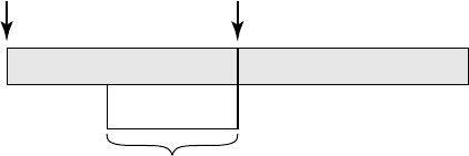
PACING THERAPIES
BASIC PARAMETERS 5-15
When the ventricular Pacing Chamber is set to BiV, the LV Offset feature
is available to help coordinate the mechanical response of the ventricles
(Figure 5-2 on page 5-15).
The device automatically accommodates the LV offset for the lowest
programmed tachy rate threshold when biventricular pacing occurs near the
upper rate limit.
AV Delay PVARP
A
trial Sense or Pace RV Pace
-100 ms
Programmable LV Pace Range
0 ms
Figure 5-2. Programmable LV pace range
NOTE: The programmed AV Delay is based on RV timing; therefore, it is not
affected by LV Offset.
Pulse Width
Pulse Width, also referred to as pulse duration, determines how long the output
pulse will be applied between the pacing electrodes.
The following considerations are important when programming Pulse Width:
• Pulse widths are independently programmable.
• The energy delivered to the heart is directly proportional to the pulse width.
Therefore, programming a shorter pulse width increases pulse generator
longevity. To prevent loss of capture, exercise caution when you are
programming permanent pulse width values of less than 0.3 ms (Figure 5-3
on page 5-16).
- DRAFT -
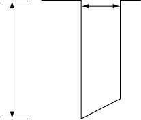
5-16 PACING THERAPIES
BASIC PARAMETERS
Pulse Width (ms)
Amplitude (V)
Figure 5-3. Pulse waveform
Amplitude
The pulse Amplitude, or voltage of the output pulse, is measured at the leading
edge of the output pulse (Figure 5-3 on page 5-16).
Amplitudes are independently programmable. The following considerations
are important:
• During temporary programming, the brady pacing mode may be
programmed to Off. In effect, this turns Amplitude off to monitor the
patient’s underlying rhythm.
• A minimum 2x voltage safety margin is recommended for each chamber
based on the capture thresholds, which should provide an adequate safety
margin and help preserve battery longevity.
• The energy delivered to the heart is directly proportional to the square
of the amplitude. In other words, doubling the amplitude quadruples
the energy delivered, which will decrease pulse generator longevity.
Programming to a lower Amplitude while maintaining an adequate safety
margin may increase battery longevity.
Sensitivity
The Sensitivity parameter allows the pulse generator to detect intrinsic cardiac
signals that exceed the programmed value.
All detection and timing decisions are based on the sensed cardiac cycle
length. These pulse generators use an automatic gain control circuit to
dynamically adjust the sensitivity.
- DRAFT -
PACING THERAPIES
POST-THERAPY PACING 5-17
• High Sensitivity (low value)—when Sensitivity is programmed to a very
sensitive setting, the pulse generator may detect signals unrelated to
cardiac depolarization (oversensing, such as sensing of myopotentials)
• Low Sensitivity (high value)—when Sensitivity is programmed to a
less sensitive setting, the pulse generator may not detect the cardiac
depolarization signal (undersensing)
POST-THERAPY PACING
Post-therapy pacing provides alternate pacing therapy following the delivery
of any shock.
The pacing mode and pacing therapies used following a shock are the same as
the programmed Normal pacing settings.
The following pacing parameters can be programmed independently from the
Normal pacing settings:
• Pacing Parameters—LRL, Amplitude, and Pulse Width
• Post Therapy Period
Post-Shock Pacing Delay
The Post-Shock Pacing Delay determines the earliest possible start of
post-shock pacing following the delivery of a ventricular shock and is fixed
at 3 seconds.
The timing of the initial pacing pulse in the Post-Therapy Period depends on
the cardiac activity during the Post-Shock Pacing Delay.
• If R-waves (and/or P-waves for dual-chamber pacing modes) are sensed
during the Post-Shock Pacing Delay, the device paces only when the
sensed rate is slower than the post-therapy LRL.
• If no R-waves (and/or P-waves for dual-chamber pacing modes) are
sensed during the Post-Shock Pacing Delay or if the interval since the
preceding P- or R-wave was greater than the escape interval, a pacing
pulse is delivered at the end of the Post-Shock Pacing Delay.
Subsequent pacing pulses are delivered as required, depending on the pacing
prescription.
- DRAFT -
5-18 PACING THERAPIES
TEMPORARY PACING
Post-Therapy Period
The Post-Therapy Period determines how long the pulse generator operates
using the post-therapy parameter values.
The Post-Therapy Period functions as follows:
• The period starts when the Post-Shock Pacing Delay expires
• On completion of this pacing period, the pulse generator reverts to the
programmed Normal pacing values
• While in process, the pacing period is not affected by the end of the current
episode
TEMPORARY PACING
The pulse generator can be programmed with temporary pacing parameter
values that differ from the programmed Normal Settings. This allows you
to examine alternate pacing therapies while maintaining the previously
programmed Normal Settings in the pulse generator memory. During the
Temporary function, all other bradycardia features are disabled.
NOTE: Post-therapy values are not affected.
To use this function, follow these steps:
1. From the Tests tab, select the Temp Brady tab to display the temporary
parameters. When the parameters are initially displayed, they are set to
the Normal Settings values ("Programmable Options" on page A-1).
NOTE: Post-therapy values are not shown even if post-therapy is presently
in effect.
2. Select the desired values; these values are independent from other pacing
functions.
3. Establish telemetry communication, then select the Start button. Pacing
begins at the temporary values. A dialog box indicates that temporary
parameters are being used, and a Stop button is provided.
NOTE: Temporary pacing cannot be started while a tachyarrhythmia episode
is in progress.
- DRAFT -
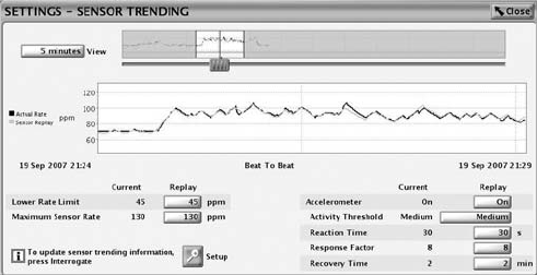
PACING THERAPIES
SENSORS AND TRENDING 5-19
NOTE: Emergency therapy is the only function that can be initiated until the
Temporary function is stopped.
4. To stop the Temporary pacing mode, select the Stop button. The Temporary
pacing mode also stops when you command emergency therapy from
the PRM or when you press the DIVERT THERAPY key. Once stopped,
the pacing reverts to the previously programmed Normal/Post-Therapy
settings.
SENSORS AND TRENDING
Sensor and trending therapies include the parameters as described.
Sensor Trending
Sensor Trending provides a graphical display of the sensor rate based on
sensor data. This feature evaluates the pulse generator’s rate response to the
patient’s detected activity level and provides useful information during exercise
testing.
The pulse generator collects and stores rate and sensor data. The rate data
represents the programmed parameters. The Sensor Replay option allows
you to adjust the parameter values and view the result without having to
repeat an exercise test. The pulse generator also collects and stores data in
nonadaptive-rate modes; however, without the sensor data comparison, only
rate data will be displayed.
The Sensor Trending screen is accessible from within Normal Settings
(Figure 5-4 on page 5-19).
Figure 5-4. Sensor Trending screen
Setup includes the following options:
- DRAFT -
5-20 PACING THERAPIES
SENSORS AND TRENDING
• Recording Method—programmable:
– 30-Second Average
– Beat to Beat
• Duration––programmable:
– When Recording Method is set to Off or 30-Second Average––fixed,
approximately 25 hours
– When Recording Method is set to Beat to Beat––fixed, approximately
40 minutes at 75 bpm
• Data Storage—programmable:
– Continuous—contains the most recent data available. Storage
starts when setup is confirmed and continuously records the latest
information, overwriting the oldest data until the information is
retrieved. This option allows you to view data for the recording duration
immediately prior to data retrieval.
– Fixed—storage starts when setup is confirmed and continues until
device memory storage is full. This allows you to view data from initial
setup for a fixedamountoftime.
– Off—when Sensor Trending is programmed to Off, no trending data
is gathered.
Select the View button to vary the time period for how much data is visible;
options exist for 1–25 hours. To adjust the vertical axis, move the slider bar
at the bottom of the display window.
Adaptive-rate Pacing
In adaptive-rate pacing modes, sensors are used to detect changes in
the patient’s metabolic demand and increase the pacing rate accordingly.
Adaptive-rate pacing is intended for patients who exhibit chronotropic
incompetence and who would benefit from increased pacing rates that are
concurrent with physical activity.
CAUTION: Adaptive-rate pacing should be used with care in patients who are
unable to tolerate increased pacing rates.
- DRAFT -
PACING THERAPIES
SENSORS AND TRENDING 5-21
When adaptive-rate parameters are programmed, the pacing rate increases
in response to increased activity, then decreases as the activity returns to a
resting level.
NOTE: Activity involving minimal upper body motion, such as bicycling, may
result in only a moderate pacing response.
NOTE: Adaptive-rate pacing has been shown to be potentially proarrhythmic.
Use caution when programming adaptive-rate features.
Accelerometer
The accelerometer detects motion that is associated with a patient’s physical
activity and generates an electronic signal that is proportional to the amount
of body motion. Based on accelerometer input, the pulse generator estimates
the patient’s energy expenditure as a result of exercise, then translates it into
a rate increase.
The pulse generator senses body motion by means of an integrated circuit
accelerometer located on the hybrid circuit. The accelerometer sensor
responds to activity in the frequency range of typical physiologic activity (1–10
Hz). The accelerometer evaluates both the frequency and the amplitude of
the sensor signal.
• Frequency reflects how often an activity occurs, such as the number of
steps taken per minute during a brisk walk
• Amplitude reflects the force of motion (e.g., the more deliberate steps
taken while walking)
Once detected, an algorithm translates the measured acceleration into a rate
increase above the LRL.
Because the accelerometer is not in contact with the pulse generator case, it
does not respond to simple static pressure on the device case.
There are three Accelerometer settings: Off, On, and ATR Only. When you
program the respective rate-responsive modes for Normal Settings and ATR
Fallback, that action automatically updates the Accelerometer setting. If the
pulse generator is permanently programmed to a nonadaptive-rate mode, it is
possible to program the ATR Fallback mode to an adaptive-rate mode using
the accelerometer sensor. In this case, the Accelerometer field will display
ATR Only.
- DRAFT -
5-22 PACING THERAPIES
SENSORS AND TRENDING
The following programmable parameters control the pulse generator’s response
to the sensor values generated by the Accelerometer:
• Activity Threshold
• Reaction Time
• Response Factor
• Recovery Time
Activity Threshold
Activity Threshold prevents rate increases due to low-intensity, extraneous
motion (e.g., motion caused by respiration, heart beat, or in some cases tremor
associated with Parkinson’s disease).
Activity Threshold represents the activity level that must be exceeded before
the sensor-driven pacing rate will increase. The pulse generator will not
increase the paced rate above the LRL until the activity signal increases
above the Activity Threshold. An Activity Threshold setting should allow a rate
increase with minor activity, such as walking, but be high enough so the pacing
rate will not increase inappropriately when the patient is inactive (Figure 5-5 on
page 5-23, Figure 5-6 on page 5-23).
• Lower setting––less motion is required to increase the pacing rate
• Higher setting––more motion is required to increase the pacing rate
• Nominal setting––shown to be appropriate for the majority of patients in a
previous Guidant study; therefore, it is recommended for use in monitoring
the rate response prior to programming changes
NOTE: Programming the Activity Threshold for Normal Settings also changes
the corresponding selection for Post-Therapy Settings.
- DRAFT -
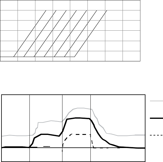
PACING THERAPIES
SENSORS AND TRENDING 5-23
Activity Threshold
MSR
LRL
Low High
Activity
Low
Medium
Med-Lo
Med-Hi
High
V-High
V-Low
Paced rate
Figure 5-5. Activity Threshold and rate response
Activity Threshold
MSR
Paced rate
LRL
Rest Stage 1 RestStage 2
Time
Lower threshold
setting
Higher threshold
setting
Nominal threshold
setting
This figure demonstrates the effect of increased or decreased Activity Threshold settings in
response to a theoretical two-stage exercise test.
Figure 5-6. Activity Threshold in exercise test
Reaction Time
Reaction Time determines how quickly the pacing rate will rise to a new level
once an increase in activity level is detected.
Reaction Time affects only the time required for a rate increase to occur. The
value selected determines the time required for the paced rate to move from
the LRL to the MSR for a maximum level of activity (Figure 5-7 on page 5-24
and Figure 5-8 on page 5-24).
• Short Reaction Time: results in a rapid increase in the pacing rate
- DRAFT -
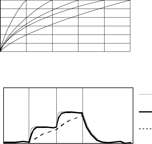
5-24 PACING THERAPIES
SENSORS AND TRENDING
• Long Reaction Time: results in a slower increase in the pacing rate
• Nominal setting: shown to be appropriate for the majority of patients in a
previous Guidant study; therefore, it is recommended for use in monitoring
the rate response prior to programming changes
Reaction Slopes
MSR
LRL
01020304050
Seconds
Paced rate
S
h
o
r
t
N
o
m
i
n
a
l
L
o
n
g
Figure 5-7. Reaction Time and paced rate
Reaction Time
MSR
LRL
Rest Stage 1 RestStage 2
Time
Shorter
Longer
Paced rate
Shorter
Reaction Time
Longer
Reaction Time
Nominal
Reaction Time
Figure 5-8. Reaction Time in exercise test
Programming Reaction Time for Normal Settings also changes the
corresponding selection for Post-Therapy Settings.
Response Factor (Accelerometer)
Response Factor (accelerometer) determines the pacing rate that will occur
above the LRL at various levels of patient activity (Figure 5-9 on page 5-25).
• High Response Factor––results in less activity required for the pacing rate
to reach the MSR
- DRAFT -
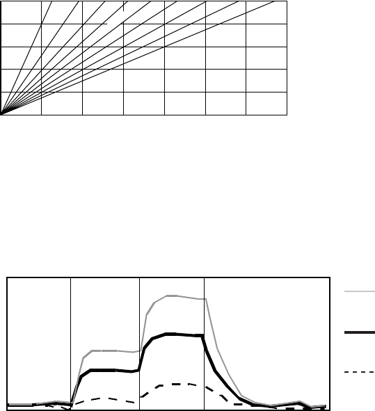
PACING THERAPIES
SENSORS AND TRENDING 5-25
• Low Response Factor––results in more activity required for the pacing
rate to reach the MSR
• Nominal setting––shown to be appropriate for the majority of patients in a
previous Guidant study; therefore, it is recommended for use in monitoring
the rate response prior to programming changes
Rate Response Slopes
16 14 12 10 8 6 4 2 1
MSR
LRL
Low High
Activity
Paced rate
Nominal
Figure 5-9. Response Factor and paced rate
The pacing rate achieved can be limited either by the detected activity level or
the programmed MSR. If the detected activity level results in a steady-state rate
below the MSR, the pacing rate can still increase when the detected activity
levels increase (Figure 5-10 on page 5-25).
Response Factor
MSR
Paced rate
LRL
Rest Stage 1 Rest Stage 2
Time
Higher Response
Setting
Lower Response
setting
Nominal
Response Setting
Lower
Higher
This figure shows the effect of higher and lower settings during a theoretical two-stage exercise test.
Figure 5-10. Response Factor in exercise test
Programming the LRL up or down moves the entire response up or down
without changing its shape. The steady-state response is independent of the
programmed reaction and recovery times.
- DRAFT -

5-26 PACING THERAPIES
SENSORS AND TRENDING
The Passive setting can be used to allow accelerometer trending without a rate
response. In this setting, the Brady Mode is programmed to a non–rate-adaptive
mode and the Recording Method for sensor trending is not programmed to Off.
Programming Response Factor for Normal Settings also changes the
corresponding selection for Post-Therapy Settings.
Recovery Time
Recovery Time determines the time required for the paced rate to decrease
from the MSR to the LRL in the absence of activity. When patient activity
concludes, Recovery Time is used to prevent an abrupt decrease in pacing rate
(Figure 5-11 on page 5-26 and Figure 5-12 on page 5-27).
• Short Recovery Time––results in a faster decrease in pacing rate after
patient activity lowers or stops
• Long Recovery Time––results in a slower decrease in pacing rate after
patient activity lowers or stops
Recovery Curves
MSR
Paced rate
LRL
0246 161412108
Minutes
There are 15 settings available; only the even-numbered settings are shown.
Figure 5-11. Recovery Time and paced rate
- DRAFT -
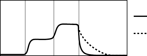
PACING THERAPIES
ATRIAL TACHY RESPONSE 5-27
Recovery Time
MSR
Paced rate
LRL
Rest Stage 1 RestStage 2
Time
Longer
Recovery Time
Nominal
Recovery Time
The figure shows the effect of higher and lower settings during a theoretical two-stage exercise test.
Figure 5-12. Recovery Time in exercise test
Programming Recovery Time for Normal Settings also changes the
corresponding selection for Post-Therapy Settings.
ATRIAL TACHY RESPONSE
ATR Mode Switch
ATR limits the amount of time that the ventricular paced rate is at the MTR
or exhibits upper-rate behavior (2:1 block or Wenckebach) in response to a
pathological atrial arrhythmia.
ATR also limits the amount of time that CRT is inhibited due to pathological
atrial tachycardia.
In the presence of detected atrial activity that exceeds the Atrial Arrhythmia
Rate Threshold, ATR switches the pacing mode from a tracking mode to a
nontracking mode as follows:
• From DDD(R) to DDI(R) or VDI(R)
• From VDD(R) to VDI(R)
An example of ATR behavior is shown (Figure 5-13 on page 5-28).
- DRAFT -
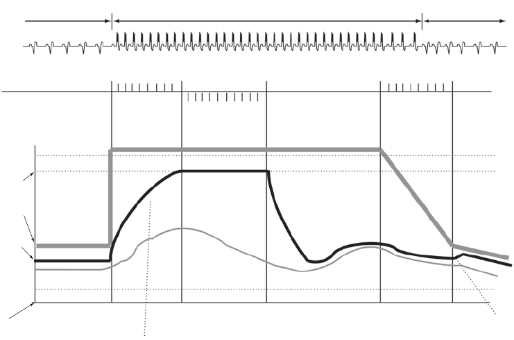
5-28 PACING THERAPIES
ATRIAL TACHY RESPONSE
CRT CRT inhibited when atrial rate > MTR
CRT restored below
Wenckebach point
Intact AV
Conduction
ATR Counter
Duration Counter
0 8
Detect Duration Fallback Reset
0 8
Exit Count = 8
8 atrial cycles <
Atrial Arrhythmia
Rate Threshold
N
Entry Count = 8
8 atrial cycles >
Atrial Arrhythmia
Rate Threshold
Atrial Arrhythmia
Rate Threshold =
170 min-1 (ppm)
MTR =
120 min-1 (ppm)
Rate
Atrial Rate
Right Ventricular
Rate
Sensor Rate
ATR/VTR Fallback
LRL = 70 min-1 (ppm)
LRL = 60 min-1 (ppm)
Atrial
tachycardia
starts
Rate Smoothing
applied here
Atrial
tachycardia
confirmed
ATR Duration
fulfilled
Atrial
tachycardia
terminates
Atrial
tachycardia
termination
confirmed
Rate
Smoothing
applied
here
MODE SWITCHING
DDDR VDIR
DDDR
Figure 5-13. ATR behavior
CAUTION: ATR should be programmed to On if the patient has a history of
atrial tachyarrhythmias. The delivery of CRT is compromised because AV
synchrony is disrupted if the ATR mode switch occurs.
When a heart failure patient has an atrial tachyarrhythmia episode, the
effectiveness of CRT is compromised because AV synchrony is disrupted.
While ATR cannot resolve AV asynchrony, it can quickly bring the biventricular
paced rate from the MTR to the ATR/VTR Fallback LRL, VRR rateor
sensor-indicated rate (DDIR or VDIR). Programming a short ATR Duration
and ATR Fallback Time allows a quicker mode switch and faster decrease in
the biventricular pacing rate.
Patients with intact AV conduction may have conducted ventricular rates during
ATR episodes. If the intrinsic ventricular rate exceeds the biventricular pacing
rate during the ATR episode, biventricular pacing will be inhibited. For these
patients, consider programming the VRR feature to On.
NOTE: In ATR, the pacing chamber is always biventricular.
- DRAFT -
PACING THERAPIES
ATRIAL TACHY RESPONSE 5-29
NOTE: Parameter settings that reduce the atrial sensing window may inhibit
ATR therapy.
Atrial Arrhythmia Rate Threshold
The Atrial Arrhythmia Rate Threshold determines the rate at which the pulse
generator begins to detect atrial tachycardias.
The pulse generator monitors atrial events throughout the pacing cycle,
except during the atrial blanking period and the noise interrogation intervals.
Atrial events faster than the Atrial Arrhythmia Rate Threshold increase the
ATR detection counter; atrial events slower than the Atrial Arrhythmia Rate
Threshold decrease the counter.
When the ATR detection counter reaches the programmed entry count, the
ATR Duration begins. When the ATR detection counter counts down from the
programmed Exit Count value to zero at any point in time, ATR Duration and/or
fallback are terminated, and the ATR algorithm is reset. An event marker is
generated whenever the ATR detection counter is incremented or decremented.
NOTE: During post-therapy pacing, ATR functions the same as in normal
pacing.
ATR Duration
ATR Duration determines the number of cardiac cycles during which the
atrial events continue to be evaluated after initial detection. This feature is
intended to avoid mode switching due to short, nonsustained episodes of atrial
tachycardia. If the ATR counter reaches zero during ATR Duration, the ATR
algorithm will be reset, and no mode switch will occur.
If the atrial tachycardia persists for the programmed ATR Duration, then
mode switching occurs and the ventricular rate begins decreasing to the
sensor-indicated rate, VRR rate or the ATR/VTR Fallback LRL, depending
on the programmed Fallback Mode.
Entry Count
The Entry Count determines how quickly an atrial arrhythmia is initially detected.
The lower the programmable value, the fewer the fast atrial events required to
fulfill initial detection. Once the number of fast atrial events detected equals
- DRAFT -
5-30 PACING THERAPIES
ATRIAL TACHY RESPONSE
the programmable Entry Count, ATR Duration begins, and the Exit Count is
enabled.
CAUTION: Exercise care when programming the Entry Count to low values
in conjunction with a short ATR Duration. This combination allows mode
switching with very few fast atrial beats. For example, if the Entry Count was
programmed to 2 and the ATR Duration to 0, ATR mode switching could occur
on 2 fast atrial intervals. In these instances, a short series of premature atrial
events could cause the device to mode switch.
Exit Count
The Exit Count determines how quickly the ATR algorithm is terminated once
the atrial arrhythmia is no longer detected.
The lower the programmed value, the more quickly the pulse generator will
return to an atrial tracking mode. Once the number of slow atrial events
detected equals the programmable Exit Count, ATR Duration and/or Fallback
will be terminated, and the ATR algorithm will be reset.
CAUTION: Exercise care when programming the Exit Count to low values.
Forexample,iftheExitCountwasprogrammedto2,afewcyclesofatrial
undersensing could cause termination of mode switching.
Fallback Mode
Fallback Mode is the nontracking pacing mode that the pulse generator
automatically switches to when ATR Duration is fulfilled.
After switching modes, the pulse generator gradually decreases the ventricular
paced rate to the ATR/VTR Fallback LRL, VRR rate, if enabled, or the
sensor-indicated rate if programmed to an adaptive-rate mode, whichever is
higher. The decrease in the ventricular paced rate is controlled by the Fallback
Time parameter.
NOTE: In Fallback Mode, the pacing chamber is biventricular.
NOTE: Dual-chamber pacing fallback mode values are only available when
the Normal pacing mode is also set to dual chamber.
- DRAFT -
PACING THERAPIES
ATRIAL TACHY RESPONSE 5-31
Fallback Time
Fallback Time controls how quickly the paced rate will decrease during fallback
to the ATR/VTR Fallback LRL, the sensor-indicated rate, or VRR if enabled.
During fallback, the following features are disabled:
• Rate Smoothing—disabled until fallback reaches the ATR/VTR Fallback
LRL, the sensor-indicated rate, or VRR; if VRR is enabled, then Rate
Smoothing is disabled throughout the mode switch
• Rate Hysteresis
• PVARP Extension
All sensor parameters must be programmed when the adaptive-rate Fallback
Mode is selected. When the pulse generator is permanently programmed to
an adaptive-rate mode with an adaptive-rate ATR Fallback Mode, the pulse
generator will use the sensor and sensor parameters already in effect at the
time of the switch. If the pulse generator is permanently programmed to a
nonadaptive rate mode, it is possible to program the ATR Fallback Mode to an
adaptive-rate ATR Fallback Mode using the accelerometer sensor. In this case,
the Accelerometer field displays ATR Only.
Fallback LRL
The ATR/VTR Fallback LRL is the programmed lower rate to which the rate
decreases during mode switching.
Consider the following interactions when programming the ATR/VTR Fallback
LRL:
• If an adaptive-rate mode is programmed and the sensor-indicated rate
is greater than the ATR/VTR Fallback LRL, the rate decreases to the
sensor-indicated rate
• If VRR is enabled and the VRR rate is greater than the ATR/VTR fallback
LRL, the rate decreases to the VRR rate
• If an adaptive-rate mode is programmed and VRR is enabled, the rate
will decrease to the faster of the sensor-indicated rate, VRR rate, and the
ATR/VTR Fallback LRL
- DRAFT -
5-32 PACING THERAPIES
ATRIAL TACHY RESPONSE
• The ATR/VTR Fallback LRL is also the Backup VVI pacing rate during
backup pacing in the presence of detected ventricular arrhythmias
End of ATR Episode
The End of ATR Episode identifies the point when the pulse generator reverts
to AV synchronous pacing because the atrial arrhythmia is no longer detected.
The pulse generator continues to pace in the Fallback Mode at the
sensor-indicated rate, the VRR-calculated rate, or the ATR Fallback LRL until
the atrial arrhythmia terminates. With the termination of the arrhythmia, the
ATR Exit Count decrements from its programmed value until it reaches 0.
The ATR Exit Count is decremented by atrial events slower than the ATR
Trigger Rate or any ventricular event that occurs more than two seconds after
the last atrial event. When the ATR Exit Count reaches 0, the pacing mode
automatically switches to the programmed tracking mode, and AV-synchronous
pacing is restored.
Ventricular Tachy Response (VTR)
VTR serves as an automatic mode switch for backup VVI pacing in the
presence of detected ventricular tachyarrhythmias.
When detection is satisfied in a ventricular tachycardia zone, the pacing mode
switches to VVI (BiV) or to Off if the current mode is AAI(R) or Off.
When the mode switches, backup pacing occurs at the programmed ATR/VTR
Fallback LRL and uses the programmed ATP ventricular Pulse Width and
Amplitude values.
The device automatically accommodates the AV delay for the lowest
programmed tachy rate threshold when atrial pacing occurs near the upper
rate limit.
Ventricular Rate Regulation (VRR)
VRR is designed to reduce the V–V cycle length variability during partially
conducted atrial arrhythmias by modestly increasing the ventricular pacing rate.
In addition, VRR preserves CRT delivery during conducted atrial arrhythmias.
The VRR algorithm calculates a VRR-indicated pacing interval based on a
weighted sum of the current V–V cycle length and the previous VRR-indicated
pacing intervals.
- DRAFT -
PACING THERAPIES
ATRIAL TACHY RESPONSE 5-33
• The degree of rate increase with sensed intervals is determined by the
programmed setting (Min, Med, Max). The influence is tempered by the
previous history because of the weighted-sum methodology stated above.
• The VRR-indicated rate is further bound by the LRL and the VRR MPR.
NOTE: VRR has the potential to increase CRT delivery during atrial
tachyarrhythmias and should be programmed on at the maximum setting to
increase the ventricular pacing percent and maximize CRT delivery during
conducted atrial tachyarrhythmias.
The programmable values affect the degree of rate regulation.
• A higher setting will increase CRT pacing more than a lower setting (i.e.,
Max vs. Med)
• A higher setting will decrease V–V variability more than a lower setting
When VRR is programmed on in tracking modes, it is only active when an ATR
mode switch has occurred. Once the tracking mode operation resumes at the
termination of the atrial arrhythmia, VRR becomes inactive. In tracking modes
where both Rate Smoothing and VRR are programmed on, whenever VRR
is active, the pulse generator automatically disables Rate Smoothing, then
reactivates it once the ATR terminates.
When programmed on in nontracking modes, VRR is continually active and
updates the VRR-indicated pacing rate on each cardiac cycle.
Ventricular Rate Regulation Maximum Pacing Rate (VRR MPR)
The VRR MPR limits the maximum pacing rate for VRR.
VRR operates between the LRL and the MPR.
Biventricular Trigger
Biventricular Trigger is designed to promote synchronized RV and LV
contractions in the presence of RV sensed events. It does this by pacing the
left and right ventricles immediately after a sensed RV event. When used in
conjunction with VRR, Biventricular Trigger is designed to provide additional
CRT support during atrial tachycardias.
- DRAFT -
5-34 PACING THERAPIES
ATRIAL TACHY RESPONSE
Biventricular Trigger may be applied during dual or single chamber ventricular
pacing modes and also during ATR Fallback.
Biventricular Trigger operates between the LRL and the MPR.
Biventricular Trigger Maximum Pacing Rate (MPR)
The Biventricular Trigger MPR limits the maximum pacing rate that Biventricular
Trigger can reach.
During VDD(R) or DDD(R) modes, MTR limits the Biventricular Trigger MPR.
Atrial Flutter Response (AFR)
Atrial Flutter Response is designed to:
• Prevent pacing into the atrial vulnerable period
• Provide immediate fallback for atrial rates higher than the AFR
programmable rate
The fallback is maintained for as long as atrial events continually exceed the
AFR programmable rate.
Example: When AFR is programmed to 170 ppm, a detected atrial event inside
the PVARP or a previously triggered AFR interval starts an AFR window of
353 ms (170 ppm). Atrial detection inside the AFR is classified as refractory
senses and is not tracked. Tracking starts only after both the AFR and the
PVARP expire. Paced atrial events scheduled inside an AFR window are
delayed until the AFR window expires. If there are fewer than 50 ms remaining
before a ventricular pace, the atrial pace is inhibited for the cycle.
This changes the programmed AV Delay and may alter the effectiveness of
CRT if the AFR rate is programmed slower than the patient’s sinus rate.
Ventricular pacing is not affected by AFR and will take place as scheduled. The
wide programmable range for AFR rates allows for appropriate sensing of
slow atrial flutters. High-rate atrial sensing may continuously retrigger the AFR
window, effectively resulting in fallback to the VDI(R) mode.
NOTE: When both AFR and ATR are active and in the presence of atrial
arrhythmias, nontracking ventricular paced behavior may occur sooner, but the
ATR mode switch may take longer.
- DRAFT -
PACING THERAPIES
RATE ENHANCEMENTS 5-35
NOTE: For atrial arrhythmias that meet the programmed AFR rate criteria,
using the AFR feature will result in slower ventricular pacing rates.
PMT Termination
PMT Termination detects and attempts to interrupt pacemaker-mediated
tachycardia (PMT) conditions.
In the DDD(R) and VDD(R) pacing modes, any device may detect and track
retrograde conducted P-waves that fall outside of PVARP, causing triggered
ventricular pacing rates as high as the MTR (i.e., PMT). When PMT Termination
is programmed to On, a PMT condition is detected when 16 successive
ventricular paces are counted at the MTR following atrial sensed events.
During the 16 intervals, the V–A interval is monitored to determine if:
• A PMT is occurring
• The intrinsic atrial rate is simply meeting the MTR or exceeding it
The V–A intervals are compared to the second V–A interval measured during
the 16 ventricular paced events.
• If any of the successive intervals is more than 32 ms shorter or longer
than this second interval, the algorithm continues to monitor successive
ventricular paces for the presence of a PMT
• If the V–A intervals are all within this 32 ms criteria, the rhythm is declared
aPMT
When PMT Termination is programmed to On, the pulse generator stores PMT
episodes in the Arrhythmia Logbook.
When a PMT condition is detected at the MTR, the pulse generator sets the
PVARP setting to a fixed setting of 500 ms for one cardiac cycle in an attempt
to break the PMT. Programming the PVARP After PVC option and/or Rate
Smoothing can also be useful in controlling the pulse generator’s response to
retrograde conduction.
RATE ENHANCEMENTS
Rate Enhancements includes the parameters as described.
- DRAFT -
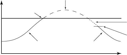
5-36 PACING THERAPIES
RATE ENHANCEMENTS
Tracking Preference
Tracking Preference is designed to maintain atrial-tracked ventricular pacing in
DDD(R) and VDD(R) modes by identifying atrial events for tracking that are
hidden in PVARP. This feature supports CRT delivery for atrial rates below but
near the MTR; otherwise, therapy might be inhibited.
Hidden atrial events can occur when a patient has a combination of a long
intrinsic intracardiac AV interval and a long PVARP. If two successive cycles
occur in which a sensed RV event is preceded by an atrial sensed event
in PVARP, the pulse generator shortens PVARP until normal atrial-tracked
ventricular pacing is established. By programming Tracking Preference to
On, continuous CRT is delivered at rates below MTR-rates which otherwise
might be inhibited when the sum of PVARP and the intrinsic intracardiac AV
interval is longer than the MTR interval.
As a result of Tracking Preference, the timing relationship between PVARP
and the atrial event is changed such that the atrial events no longer fall within
PVARP. Timing is changed by the pulse generator’s use of the programmed AV
Delay instead of the intracardiac AV interval. The effect of Tracking Preference
on atrial rates is illustrated below (Figure 5-14 on page 5-36).
NOTE: Tracking Preference is disabled if the atrial rate interval is greater
than or equal to the MTR interval. This prevents the tracking of potentially
pathological atrial rates and PMT.
PVARP + intrinsic
intracardiac AV interval
Pacing rate reaches MTR,
Ventricular events are sensed.
Ventricular sense
MTR Pacing if Tracking Preference
is On; No pacing if Tracking
Preference is Off.
Ventricular pace
Time
Ventricular pace
Rate
Figure 5-14. Tracking Preference on atrial events hidden in PVARP
Rate Hysteresis
Rate Hysteresis can improve device longevity by reducing the number of
pacing stimuli. This feature is available in DDD and AAI modes and is activated
by a single nonrefractory, sensed atrial event.
- DRAFT -
PACING THERAPIES
RATE ENHANCEMENTS 5-37
Hysteresis is deactivated by the following:
• A single atrial pace at the hysteresis rate
• In DDD mode:
– AsingleatrialpaceduringacardiaccyclewhenanRVpaceis
scheduled at the hysteresis LRL
– An atrial rate that rises above the MTR
When Rate Smoothing Down is enabled, Rate Hysteresis remains in effect until
pacing occurs at the hysteresis rate. This allows Rate Smoothing to control
the transition to the hysteresis rate.
Hysteresis Offset
Hysteresis Offset is used to lower the escape rate below the LRL when the
pulse generator senses intrinsic atrial activity.
If intrinsic activity below the rate limit occurs, then Hysteresis Offset allows
inhibition of pacing until the LRL minus Hysteresis Offset is reached. As a
result, the patient might benefit from longer periods of sinus rhythm.
Search Hysteresis
When Search Hysteresis is enabled, the pulse generator periodically lowers the
escape rate by the programmed Hysteresis Offset in order to reveal potential
intrinsic atrial activity below the LRL.
During Search Hysteresis, the pacing rate is lowered by the Hysteresis Offset
for up to 8 cardiac cycles. When the search ends, hysteresis remains active
if intrinsic atrial activity is sensed during that period. If there is no intrinsic
atrial activity during the 8-cycle search, pacing resumes at the LRL. If Rate
Smoothing Up is enabled, pacing will rate smooth up to the LRL.
Example: At a rate of 70 ppm and a search interval of 256 cycles, a search
for intrinsic atrial activity would occur approximately every 3.7 minutes
(256 ÷ 70 = 3.7).
Rate Smoothing is disabled during the search cycles. If no intrinsic atrial activity
is detected during the search, the pacing rate is brought up to the LRL. If Rate
Smoothing Up is enabled, the pacing will rate smooth up to the LRL.
- DRAFT -
5-38 PACING THERAPIES
RATE ENHANCEMENTS
Rate Smoothing
Rate Smoothing controls the pulse generator’s response to atrial and/or
ventricular rate fluctuations that cause sudden changes in pacing intervals.
Rate Smoothing is an important enhancement to ATR because it can
significantly reduce the rate fluctuations associated with the onset and
cessation of atrial arrhythmias.
Patients who experience large variations in their ventricular paced rate can
feel symptomatic during these episodes. Rate Smoothing can prevent these
sudden rate changes in patients along with the accompanying symptoms (such
as palpitations, dyspnea, and dizziness).
In a normal conduction system, limited cycle-to-cycle rate variations occur.
However, the paced rate can change dramatically from one beat to the next in
the presence of any of the following:
• Sinoatrial disease such as sinus pause or arrest, sinoatrial block, and
brady-tachy syndrome
• PACs and/or PVCs
• Pacemaker Wenckebach
• Intermittent, brief, self-terminating SVTs, and atrial flutter/fibrillation
• Retrogradely conducted P-waves
• Pulse generator sensing of myopotential signals, EMI, crosstalk, etc.
Rate Smoothing operates between the LRL and the MTR when programmed
to DDD(R) or VDD(R), and it operates between the LRL and the MPR when
programmed to DDI(R).
When the sensor is enabled and MSR is higher than MTR and MPR, the
operational range is from LRL to MSR. Rate Smoothing is also applicable
between the hysteresis rate and LRL when hysteresis is active, except during
Search Hysteresis.
When Rate Smoothing is programmed to On, the following information applies.
- DRAFT -
PACING THERAPIES
RATE ENHANCEMENTS 5-39
• Programmable Rate Smoothing values are a percentage of the RV
R–R interval (3% to 25% in 3% increments) and can be independently
programmed for:
– Increase—Rate Smoothing Up
– Decrease—Rate Smoothing Down
–Off
• The pulse generator stores the most recent R–R interval in memory.
R-waves may be either intrinsic or paced. Based on this R–R interval
and the programmed Rate Smoothing value, the device sets up two
synchronization windows for the next cycle: one for the atrium and one
for the right ventricle.
• Rate Smoothing is functional except:
– During the 8 cycles of rate Search Hysteresis
– During ATR Fallback until fallback reaches the ATR LRL, the
sensor-indicated rate, or the VRR interval
– During VRR when active
– Upon triggering PMT Termination
– Immediately following programmed LRL increases
– When above the MTR
Rate Smoothing Example Based on a Dual-Chamber Tracking Mode
Based on the most recent R–R interval stored in memory and the programmed
Rate Smoothing value, the pulse generator sets up the two synchronization
windows for the next cycle: one for the atrium and one for the ventricle. The
synchronization windows are defined below:
Ventricular synchronization window: previous R–R interval ± Rate
Smoothing value
Atrial synchronization window: (previous R–R interval ± Rate Smoothing
value) - AV Delay
- DRAFT -
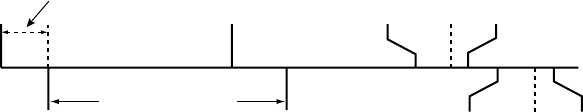
5-40 PACING THERAPIES
RATE ENHANCEMENTS
The following example explains how these windows are calculated (Figure 5-15
on page 5-40):
• Previous R–R interval = 800 ms
• AV Delay = 150 ms
• Rate Smoothing Up = 9%
• Rate Smoothing Down = 6%
Thewindowswouldbecalculatedasfollows:
Ventricular Synchronization Window = 800 - 9% to 800 + 6% =
800 ms - 72 ms to 800 ms + 48 ms = 728 ms to 848 ms
Atrial Synchronization Window = Ventricular Synchronization Window - AV
Delay = 728 ms - 150 ms to 848 ms - 150 ms = 578 ms to 698 ms
The timing for both windows is initiated at the end of every R–R interval (RV
event or LV paces when the Pacing Chamber is programmed to LV).
If paced activity is to occur, it must occur within the appropriate synchronization
window.
Paced AV Delay (150 ms)
A
trial
Event
Atrial
Event
R-R Interval (800 ms)
RV Event
Atrial Smoothing Window
578 ms 650 ms 698 ms
RV Smoothing Window
728 ms 800 ms 848 msRV Event
Figure 5-15. Rate smoothing synchronization window
It is important to ascertain the patient’s physiologic cycle-to-cycle variation
and program the Rate Smoothing parameter to a value that protects against
pathologic interval changes, yet allows physiologic interval changes in response
to increases in activity or exercise.
NOTE: Without Rate Smoothing, a sudden, large atrial rate increase (e.g.,
PAT) will cause a simultaneous sudden increase in the paced ventricular rate
as high as the programmed MTR. With Rate Smoothing, the ventricular paced
rate in response to such a change might not reach the programmed MTR.
- DRAFT -
PACING THERAPIES
RATE ENHANCEMENTS 5-41
Rate Smoothing Up
Rate Smoothing Up controls the largest pacing rate increase allowed when the
intrinsic or sensor rate is increasing.
NOTE: Rate Smoothing Up will transiently modify the programmed AV
Delay. This could change the effectiveness of the AV Delay recommended
with SmartDelay optimization.
When Rate Smoothing Up is programmed on, CRT is compromised during
episodes of atrial rate increases that exceed the programmed value.
• For patients with AV block, this occurs because Rate Smoothing prolongs
the AV Delay from the optimal setting as it controls the biventricular pacing
rate while the atrial rate increases.
• For patients with normal AV conduction, biventricular stimulation (CRT)
may be inhibited in one or more cycles during the rate smoothing operation
because intrinsic AV conduction may occur during the prolonged AV Delay
and inhibit ventricular pacing.
While the effect of the Rate Smoothing Up operation may only be transient and
its impact on CRT minimal, consider the following recommendations when
programming this parameter on.
• Address only patient-specific, sudden atrial rate increases.
• Use the highest value that can achieve the desired control because the
higher the value, the less the impact on the AV Delay extension.
Rate Smoothing Down
Rate Smoothing Down controls the largest pacing rate decrease allowed when
the intrinsic or sensor rate is decreasing.
CRT delivery is not altered by programming Rate Smoothing Down on.
However, it is important to consider that when Rate Smoothing Down is on in
the DDD(R) mode, atrial pacing will occur during the downward rate smoothing
operation. The AV Delay for optimal CRT may be different during atrial pacing
than during intrinsic sinus rhythm.
- DRAFT -
5-42 PACING THERAPIES
LEAD CONFIGURATION
NOTE: When Rate Smoothing Down is programmed on and Rate Smoothing
Up is programmed off, the pulse generator will automatically prevent fast
intrinsic beats (e.g., PVCs) from resetting the Rate Smoothing Down escape
rate any faster than 12% per cycle.
Rate Smoothing Maximum Pacing Rate (MPR)
The Rate Smoothing Maximum Pacing Rate places a limit on the maximum
pacing rate that Rate Smoothing can reach.
The Rate Smoothing Down parameter requires a programmed MPR when in
AAI, VVI, or DDI. Rate Smoothing will then be used only between the MPR and
the LRL or the hysteresis rate (if applicable).
When both VRR and Rate Smoothing are programmed on in the VVI(R) or
DDI(R) mode, VRR will have priority; Rate Smoothing will be suspended.
LEAD CONFIGURATION
The pulse generator has independent outputs for the following:
•Atrium
• Right Ventricle
• Left Ventricle
The atrial and RV leads are set to Bipolar pacing and sensing. The atrial lead
has the option of being programmed Off.
The Lead Settings screen (accessible from Normal Settings) allows you to
choose pacing and sensing configurations for the LV lead.
Left Ventricular Electrode Configuration
The LV electrode configuration provides programmable options for LV lead
pacing and sensing.
CAUTION: Proper programming of the LV coronary venous lead configuration
is essential for proper LV lead function. Program the lead configuration in
accordance with the number of electrodes on the LV lead; otherwise, erratic LV
sensing, loss of LV pacing, or ineffective LV pacing might occur.
The following programming options are available:
- DRAFT -
PACING THERAPIES
LEAD CONFIGURATION 5-43
•Dual—used when an LV lead with two electrodes is implanted
•Single—used when an LV lead with only one electrode is implanted
•None—used when an LV lead is not implanted. These pulse generators are
intended for use with an LV lead; however, there may be clinical situations
such as those described below in which an LV lead is not used:
– The LV lead cannot be positioned, and a decision is made to temporarily
use the pulse generator without an LV lead (plug the unused LV port).
– The LV lead dislodges to a suboptimal position, and a decision is made
to leave the lead implanted and connected but not use it.
The pulse generator cannot detect whether an LV lead is present or absent.
When None is selected, the Pacing Chamber must be RV only, which will result
in no LV sensing or LV pacing. With this option, the following are unavailable:
• LV electrograms
•LVmarkers
• LV intervals
• SmartDelay optimization
• LV Daily measurements
Any time a change is made to the electrode configuration, it is important to
verify lead system baseline measurements to ensure optimal functioning.
The programmed selections are reflected in the electrode configuration
illustration on the programmer screen (Figure 5-16 on page 5-44).
- DRAFT -
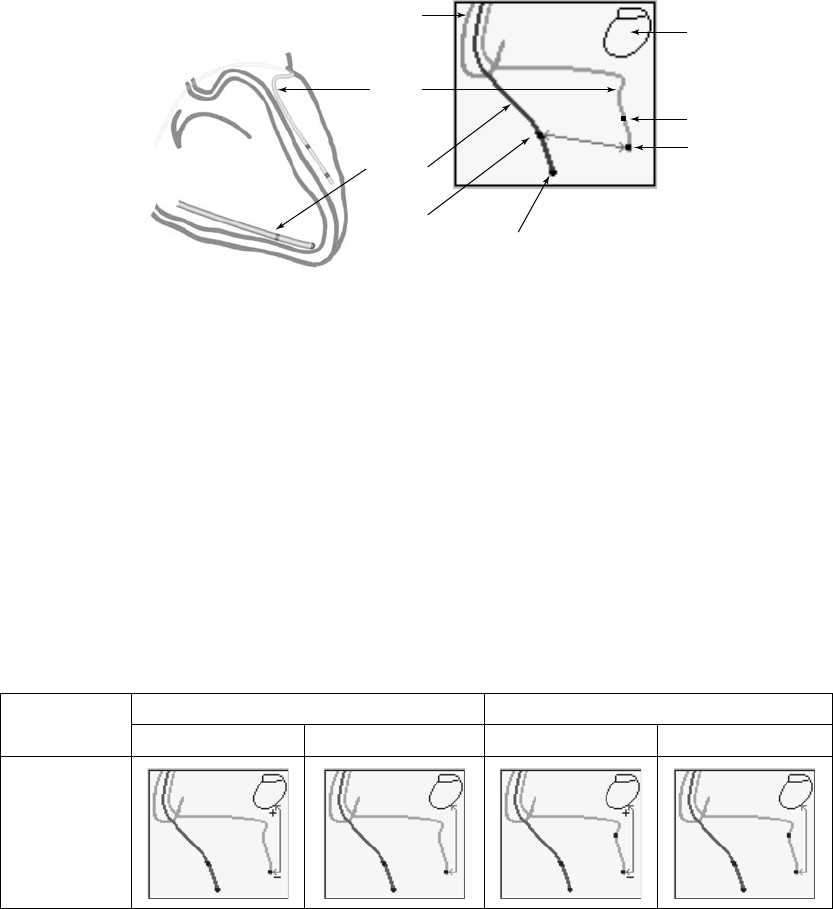
5-44 PACING THERAPIES
LEAD CONFIGURATION
Heart
LV Sense
RV Tip
RV Ring
Pulse
Generator
Can
Atrial Lead
LV Lead
LV Ring
LV Tip
RV Lead
Left illustration: heart with LV and RV leads. Right illustration: leads on the programmer screen.
Figure 5-16. Heart, LV, and RV lead in situ
LV Pace and Sense Configurations
Multiple LV pace and sense configurations are available for the lead, allowing
you to change the pacing or sensing vectors for increased signal selection.
Additional programming options are available when a dual-electrode LV lead
is implanted and the corresponding electrode configuration is programmed
to Dual.
Illustrations of pace and sense configurations are shown below (Table 5-1 on
page 5-44).
Table 5-1. Programming options for the LV lead configuration
Single Electrode Dual Electrode
Programmable
Value Pace Sense Pace Sense
LVtip>>Can
(Unipolara)
- DRAFT -
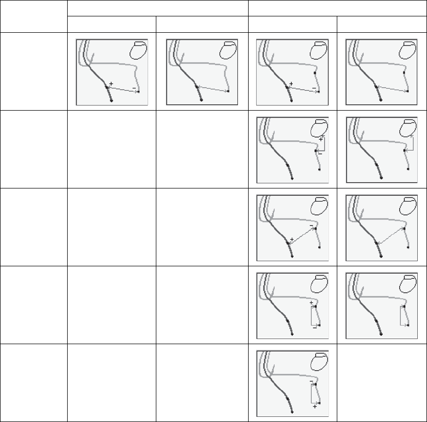
PACING THERAPIES
LEAD CONFIGURATION 5-45
Table 5-1. Programming options for the LV lead configuration (continued)
Single Electrode Dual Electrode
Programmable
Value Pace Sense Pace Sense
LVtip>>RV
(Extended
Bipolarc)
LVring>>Can
(Unipolara)
N/A LV Offd
LVring>>RV
(Extended
Bipolarc)
N/A N/A
LVtip>>LVring
(Bipolarb)
N/A N/A
LVring>>LVtip
(Bipolarb)
N/A N/A LV Offd
a. Unipolar: from one of the LV electrodes to the pulse generator can.
b. Bipolar: between the LV tip and the LV ring electrode; refers to a circuit where current travels between 2 electrodes located
on the same lead—in this case, the LV lead.
c. Extended Bipolar: from one of the LV electrodes to the RV electrode; refers to a circuit where current travels between the cathode
(negative [–] electrode) on the LV lead and the anode (positive [+] electrode) on the bipolar RV lead.
d. This configuration can be programmed to Off, which may be useful in instances such as lead fracture.
- DRAFT -
5-46 PACING THERAPIES
AV DELAY
NOTE: If LV electrograms were available at the start of temporary Brady/CRT
pacing, then they will continue to be available. However, if LV electrograms
were unavailable at the start of temporary Brady/CRT pacing, then they will
continue to be unavailable.
AV DELAY
AV Delay is the programmable time period from the occurrence of either a
paced or sensed right atrial event to a paced RV event when the Ventricular
Pacing Chamber is programmed to BiV or RV only.
AV Delay helps preserve the heart’s AV synchrony. If a sensed ventricular
event does not occur during the AV delay following an atrial event, the pulse
generator delivers a ventricular pacing pulse when AV Delay expires.
AV Delay can be programmed to the following operations:
• Paced AV Delay
• Sensed AV Delay
CAUTION: To ensure a high percentage of biventricular pacing, the
programmed AV Delay setting must be less than the patient’s intrinsic PR
interval.
This behavior occurs under the following conditions:
• Pacing state: Normal, Post-Therapy, or Temporary
• Pacing mode: DDD(R), DDI(R), or VDD(R)
Paced AV Delay
Paced AV Delay corresponds to the AV Delay following an atrial pace.
The Paced AV Delay setting should be individualized for each patient to ensure
consistent CRT delivery. Several methods are available to determine the Paced
AV Delay setting, including:
• Intrinsic QRS duration assessment
• Echocardiogram evaluation
• Pulse pressure monitoring
- DRAFT -
PACING THERAPIES
AV DELAY 5-47
The following technique was a suggested protocol during the CONTAK CD
Study:
1. Program progressively shorter Paced AV Delay settings until the maximum
pre-excitation is observed.
2. Shorten the Paced AV Delay by an additional 50 ms but no lower than
70 ms.
3. If the Paced AV Delay is still greater than 200 ms, program the Paced
AV Delay to 200 ms.
4. Evaluate the ventricular pacing function with a Holter recording, if possible,
to ensure pacing without significant fusion or pseudofusion.
5. Evaluate the patient’s intrinsic PR interval (intrinsic intracardiac AV
interval) during exercise. Dynamic AV Delay is permitted for patients who
demonstrate significant shortening of the PR interval during exercise.
Since optimization of the Paced AV Delay can significantly influence CRT
effectiveness, consider using methods that demonstrate the hemodynamic
impact of different Paced AV Delay settings, such as echocardiography or pulse
pressure monitoring.
When the minimum value is less than the maximum value, then the Paced AV
Delay is scaled dynamically according to the current pacing rate. Dynamic AV
Delay provides a more physiologic response to rate changes by automatically
shortening the Paced AV Delay or Sensed AV Delay with each interval during
an increase in atrial rate. This helps minimize the occurrence of large rate
changes at the upper rate limit and allows one-to-one tracking at higher rates.
Dynamic AV Delay was not evaluated in the CONTAK CD study.
When using Dynamic AV Delay, consider evaluating the Paced AV Delay in
effect when the patient has an elevated heart rate to ensure that CRT is still
effective.
The pulse generator automatically calculates a linear relationship based on
the interval length of the previous A–A cycle and the programmed values for
the following:
• Minimum AV Delay
• Maximum AV Delay
- DRAFT -
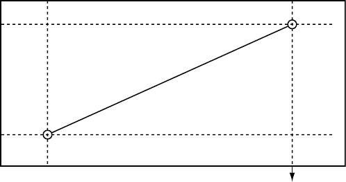
5-48 PACING THERAPIES
AV DELAY
•LRL
•MTR
•MSR
The dynamic AV Delay is not adjusted following a PVC or when the previous
cardiac cycle was limited by the MTR.
When the atrial rate is between the LRL and the higher of the MTR and the
MSR, the pulse generator calculates the linear relationship to determine the
Dynamic AV Delay (Figure 5-17 on page 5-48).
Maximum
AV Delay
Minimum
AV Delay
Higher of MTR
and MSR interval LRL Interval
Dynamic AV Delay
Figure 5-17. Dynamic AV Delay linear relationship
Dynamic AV Delay is activated during Paced AV Delay programming. The AV
delaymaybeprogrammedtoeitherafixed or dynamic value as follows:
• Fixed AV Delay—occurs when Paced AV Delay minimum and maximum
values are equal
• Dynamic AV Delay—occurs when Paced AV Delay minimum and maximum
values are not equal
Sensed AV Delay
Sensed AV Delay corresponds to the AV Delay after a sensed atrial event.
Sensed AV Delay may be programmed to a value shorter than or equal to the
Paced AV Delay. A shorter value is intended to compensate for the difference
in timing between paced atrial events and sensed atrial events (Figure 5-18 on
page 5-49).
- DRAFT -
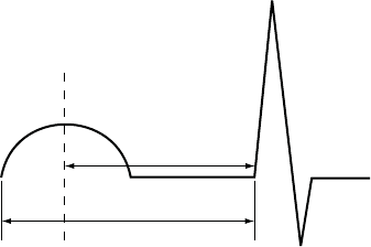
PACING THERAPIES
AV DELAY 5-49
SAV
PAV
Ap As Vp
Ap = Paced atrial event
As = Sensed atrial event
Vp = Paced ventricular event
SAV = Sensed AV Delay (As-Vp interval)
PAV = Paced AV Delay (Ap-Vp interval)
Figure 5-18. Sensed AV Delay
The hemodynamic impact of the Sensed AV Delay depends on the
appropriateness of the timing between the atrial and ventricular contractions.
An atrial pace starts the atrial contraction, whereas the atrial sense occurs
during the contraction. As a result, when Sensed AV Delay is programmed to
the same value as Paced AV Delay, the hemodynamic AV interval will differ
between paced and sensed atrial events.
When the DDD(R) mode is used to deliver biventricular stimulation (CRT), it
may be necessary to program different Paced and Sensed AV Delay settings
to optimize CRT during normal sinus rhythm and during atrial pacing because
atrial pacing may prolong the interatrial delay. The prolonged interatrial delay
may require a longer Paced AV Delay to achieve an optimal timing relationship
between left atrial activation and biventricular pacing.
When programmed to DDD(R), it is recommended that the patient be tested to
determine the optimal AV Delay during atrial sensing and atrial pacing. If the
optimal AV Delays are different, this can be reflected by programming different
Paced AV Delay and Sensed AV Delay parameter settings.
Using Sensed AV Delay with Paced AV Delay—Fixed
When Paced AV Delay is programmed to a fixed value (i.e., the minimum and
maximum Paced AV Delay values are the same), then the Sensed AV Delay
will be fixed at the programmed Sensed AV Delay value.
Using Sensed AV Delay with Paced AV Delay—Dynamic
When Paced AV Delay is programmed as dynamic (i.e., the minimum Paced
AV Delay value is programmed at less than the maximum Paced AV Delay
value), then the Sensed AV Delay will also be dynamic.
- DRAFT -
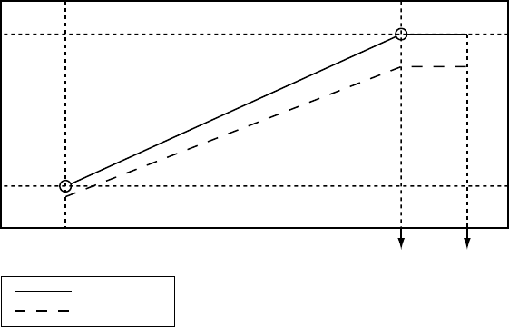
5-50 PACING THERAPIES
AV DELAY
Dynamic Sensed AV Delay and Paced AV Delay are based on the atrial rate. To
reflect the shortening of the PR interval during periods of increased metabolic
demand, the AV Delay shortens linearly from the programmed (maximum)
value at the LRL to a value determined by the ratio of minimum and maximum
AV Delay at the higher of the MTR or MSR (Figure 5-19 on page 5-50). When
Dynamic AV Delay is used, if the Sensed AV Delay value is programmed as
shorter than the maximum Paced AV Delay value, then the Sensed AV Delay
value will also be shorter than the minimum Paced AV Delay value at upper
rates.
Maximum
Paced AV
Delay
Minimum
Paced AV
Delay
Shorter of MTR
or MSR Interval LRL Interval Hysteresis Rate
Interval
Paced AV Delay
Sensed AV Delay
Figure 5-19. Dynamic and Sensed AV Delay as a function of the escape interval
NOTE: The minimum value is programmable only in VDD(R) mode.
SmartDelay Optimization
The SmartDelay optimization test uses atrial sensed and paced events to
determine suggested settings for the following:
• Paced AV Delay
• Sensed AV Delay
• Ventricular Pacing Chamber
•LVOffset
These suggested settings can be used when programming the pulse generator
for CRT.
- DRAFT -
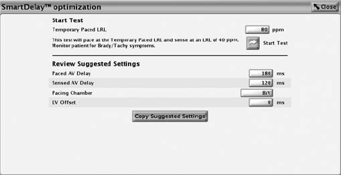
PACING THERAPIES
AV DELAY 5-51
NOTE: Before making a programming change, it is important to assess
whether the suggested settings are appropriate for the patient.
The SmartDelay optimization screen is shown below (Figure 5-20 on page
5-51).
Figure 5-20. SmartDelay optimization screen
SmartDelay optimization automatically switches to a unipolar sensing
configuration (LVtip>>Can) for the duration of the test. The test runs
automatically when Start Test is pressed. The SmartDelay optimization test will
not run under the following conditions:
NOTE: Tachy therapy is disabled while the test is in progress.
• During the post-therapy period
• When the LV Electrode Configuration is programmed to None
• DuringanATRmodeswitch
• During a tachycardia episode as determined by the pulse generator
detection criteria
NOTE: When collecting atrial sensed events during the test, backup DDD
pacing is provided at 40 ppm.
NOTE: When collecting atrial paced and sensed events, backup DDD pacing
is provided at the temporary LRL, which can be selected from the SmartDelay
optimization screen. This temporary LRL is nominally set to 80 ppm.
Follow these steps to run the SmartDelay optimization test.
1. From the Normal Settings screen, select the mode.
- DRAFT -
5-52 PACING THERAPIES
REFRACTORY
• In DDD(R) mode, the recommendation is for both Paced AV Delay
and Sensed AV Delay.
• In VDD(R) mode, the recommended AV Delay is the Sensed AV Delay;
the Paced AV Delay does not apply.
When changing modes from DDD(R) to VDD(R) or vice versa, it is
important to rerun the SmartDelay optimization test.
2. Select the SmartDelay optimization button.
3. Maintain telemetry throughout the test.
4. Before beginning the test, advise the patient to remain still and to avoid
talking during the test.
5. Press the Start Test button. A notification window indicates that the test is in
progress. If it is necessary to cancel the test, select the Cancel Test button.
NOTE: The test is automatically cancelled if a STAT PACE, STAT SHOCK, or
DIVERT THERAPY command is selected.
6. When the test is complete, the test date is displayed and saved, and the
suggested settings appear. For ease in programming, select the Copy
Suggested Settings button to transfer the suggested settings to the Normal
Brady and CRT Settings screen.
REFRACTORY
Refractory includes the features as described.
A-Refractory (PVARP)
PVARP is definedaccordingtothepacingmode:
Single-chamber atrial modes: AAI(R)—the time period after a sensed or
paced atrial event when an atrial sense event does not inhibit an atrial pace.
Dual-chamber modes: DDD(R), DDI(R), VDD(R)—the time period after a
sensed or paced RV event when an atrial event does not inhibit an atrial
pace or trigger a ventricular pace. The atrial refractory period prevents the
tracking of retrograde atrial activity initiated in the ventricle.
- DRAFT -
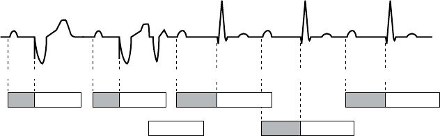
PACING THERAPIES
REFRACTORY 5-53
For heart failure patients with intact AV conduction, a long intrinsic intracardiac
AV interval and a long programmed PVARP can cause the loss of atrial tracking
below the MTR, resulting in the loss of biventricular stimulation (CRT). If an
atrial event, such as a PAC or a P-wave that immediately follows a PVC, falls
into PVARP, it will not be tracked. This allows for AV conduction of an intrinsic
ventricular event, which restarts PVARP. Unless the next atrial event occurs
outside of PVARP, it too will not be tracked, and another intrinsic AV-conducted
ventricular event will occur, again restarting PVARP. This pattern can continue
until an atrial event is finally sensed outside of PVARP (Figure 5-21 on page
5-53).
AV PVARP AV PVARP PR PVARP PR PVARP
PVARP PR PVARP
As Vp As Vp (As)PVC Vs (As) Vs (As) Vs
Figure 5-21. Atrial sensed event in PVARP
If you believe a loss of atrial tracking below the MTR is occurring, program
Tracking Preference to On. If the loss of CRT below MTR continues to be
a problem or if Tracking Preference is not used, consider reprogramming a
shorter PVARP.
For heart failure patients with second- and third-degree AV block, programming
long atrial refractory periods in combination with certain AV Delay periods can
cause 2:1 block to occur abruptly at the programmed MTR.
In DDD(R) and VDD(R) pacing modes, the pulse generator may detect
retrograde conduction in the atrium, causing triggered ventricular pacing rates
as high as the MTR (i.e., PMT). Retrograde conduction times may vary over
a patient’s lifetime as a function of changing autonomic tone. If testing does
not reveal retrograde conduction at implantation, it may still occur at a later
time. This problem can usually be avoided by increasing the atrial refractory
period to a value that exceeds the retrograde conduction time. In controlling
the pulse generator’s response to retrograde conduction, it may also be useful
to program the following:
•PVARPafterPVC
• PMT Termination
• Rate Smoothing
- DRAFT -
5-54 PACING THERAPIES
REFRACTORY
PVARP after PVC
PVARP after PVC is designed to help prevent PMT due to retrograde
conduction, which is typically associated with PVCs.
When the pulse generator detects a sensed RV event without a preceding
sensed or paced atrial event, including sensed events in refractory (i.e., a
PVC), the atrial refractory period automatically extends to the programmed
PVARP after PVC value for one cardiac cycle. After a PVC is detected, the
timing cycles reset automatically. PVARP extends no more frequently than
every other cardiac cycle.
For heart failure patients with intact AV conduction, PVARP after PVC has the
potential to cause inhibition of CRT if the atrial cycle length is shorter than the
intrinsic intracardiac AV interval (PR interval) + PVARP. If this occurs, program
Tracking Preference to On in conjunction with the PVARP after PVC feature.
RV-Refractory (RVRP)
The RVRP provides an interval following an RV pace event, or leading
ventricular pace event when LV Offset is not programmed to zero, during which
RV sensed events do not impact the timing of therapy delivery.
The use of a long RVRP shortens the RV sensing window for ventricular tachy
detection.
RVRP is available in any mode where ventricular sensing is enabled, and RVRP
canbeprogrammedtoafixed or dynamic interval (Figure 5-22 on page 5-55):
• Fixed—RVRP remains at the programmed, fixed RVRP value between the
LRL and the applicable upper rate limit (MPR, MTR or MSR).
• Dynamic—RVRP shortens as ventricular pacing increases from the LRL to
the applicable upper rate limit, allowing more time for RV sensing.
– Maximum—if the pacing rate is less than or equal to the LRL (i.e.,
hysteresis), the programmed Maximum VRP is used as the RVRP.
– Minimum—if the pacing rate is greater than or equal to the applicable
upper rate limit, the programmed Minimum VRP us used as the RVRP.
- DRAFT -
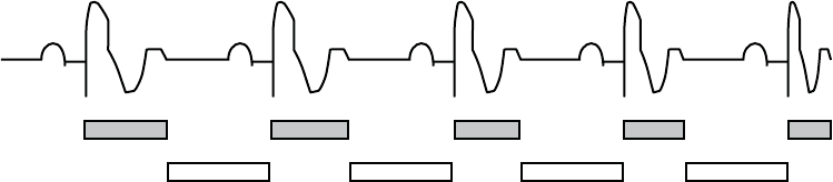
PACING THERAPIES
REFRACTORY 5-55
Dynamic VRP
shortens
Sensing window
is constant
Figure 5-22. Relationship between ventricular rate and refractory interval
To provide an adequate sensing window, the following refractory value
programming is strongly recommended:
• Single-chamber modes—less than or equal to one-half the LRL in ms
• Dual-chamber modes—less than or equal to one-half the applicable upper
rate limit
LV-Refractory (LVRP)
The LVRP prevents sensed electrical events from causing an inappropriate loss
of CRT following a sensed or paced event, such as a left-sided T-wave. Proper
programming of this feature will help maximize CRT delivery while reducing the
risk of accelerating the patient’s rhythm to a ventricular tachyarrhythmia.
CRT should be delivered continuously to maximize the patient benefit; however,
there are circumstances when it may be appropriate to inhibit therapy delivery.
LVRP provides an interval following an LV sense or pace event, or leading
ventricular pace event when LV Offset is not programmed to zero, during which
LV sensed events do not impact the timing of therapy delivery. Use of a long
LVRP shortens the LV sensing window.
LVRP is available in any mode where LV sensing is enabled. The LV interval
remains at the programmed fixed value between the LRL and the applicable
upper rate limit.
LV oversensing of a T-wave may inhibit LV pacing. To prevent inappropriate
inhibition of LV pacing, program LVRP to a duration sufficiently long to include
the T-wave.
Left Ventricular Protection Period (LVPP)
The LVPP prevents the pulse generator from inadvertently delivering a pacing
stimulus during the LV vulnerable period if, for example, a left-sided PVC
- DRAFT -
5-56 PACING THERAPIES
REFRACTORY
occurs. Proper programming of this feature will help maximize CRT delivery
while reducing the risk of accelerating the patient’s rhythm to a ventricular
tachyarrhythmia.
CRT should be delivered continuously to maximize the patient benefit; however,
there are circumstances when it may be appropriate to inhibit therapy delivery.
LVPP is the period after a paced or sensed LV event when the pulse generator
will not pace the left ventricle. LVPP prevents the pulse generator from pacing
into the LV vulnerable period.
CAUTION: Use of a long LVPP reduces the maximum LV pacing rate and
may inhibit CRT at higher pacing rates.
NOTE: If LVPP inhibits in LV-only, the pulse generator will issue an RV pace
for bradycardia support.
LVPP is available in any mode where ventricular sensing and LV pacing are
enabled.
Blanking and Noise Rejection
Blanking is the first part of the refractory period where sense amplifiers are
completely disabled. It is used to prevent cross-chamber sensing and inhibition.
During a blanking interval, the sensing circuit in one chamber ignores sensed
electrical activity generated by a pulse generator pulse in the other chamber
(crosstalk).
• If ventricular pacing were sensed in the atrium, it would initiate an
inappropriately high ventricular pacing rate in any pulse generator
attempting to maintain AV synchrony. Therefore, in DDD(R), DDI(R), and
VDD modes, a ventricular pace initiates a programmable atrial blanking
interval.
• If atrial pacing were sensed in the ventricle, it would inhibit ventricular
pulses and thereby cause an inappropriate decrease in paced rate.
Therefore, in DDD(R) and DDI(R) modes, an atrial pace initiates a
programmable ventricular blanking interval.
RV-Blank after A-Pace
RV-Blank after A-Pace, a cross-chamber blanking period, inhibits RV sensing
following an atrial pace.
- DRAFT -
PACING THERAPIES
REFRACTORY 5-57
If the value is programmed to Smart, the pulse generator automatically
adjusts the sensitivity value in order to reject far-field atrial events. This
allows for sensing of true ventricular events that had previously fallen in the
cross-chamber blanking period.
LV-Blank after A-Pace
LV-Blank after A-Pace, a cross chamber blanking period, inhibits LV sensing
following an atrial pace.
If the value is programmed to Smart, the pulse generator automatically
adjusts the sensitivity value in order to reject far-field atrial events. This
allows for sensing of true ventricular events that had previously fallen in the
cross-chamber blanking period.
A-Blank after V-Pace
A-Blank after V-Pace, a cross-chamber blanking period, inhibits atrial sensing
following an RV or LV ventricular pace.
If the value is programmed to Smart, the pulse generator automatically adjusts
the sensitivity value in order to reject far-field ventricular events. This allows
for sensing of true atrial events that had previously fallen in the cross-chamber
blanking period.
A-Blank after RV-Sense
A-Blank after RV-Sense, a cross-chamber blanking period, inhibits atrial
sensing following an RV sensed event.
If the value is programmed to Smart, the pulse generator automatically adjusts
the sensitivity value in order to reject far-field ventricular events. This allows
for sensing of true atrial events that had previously fallen in the cross-chamber
blanking period.
Refer to the following illustrations:
- DRAFT -
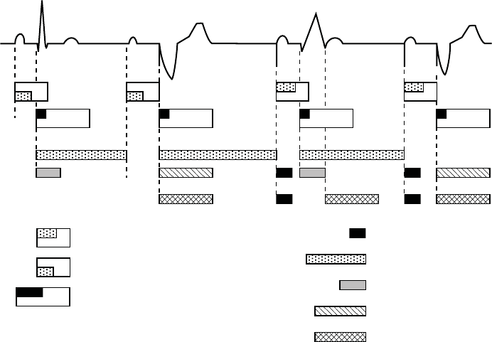
5-58 PACING THERAPIES
REFRACTORY
AV Delay after paced atrial event (programmable,
includes 150 ms absolute refractory)
AV Delay after sensed atrial event (programmable,
includes 85 ms absolute refractory)
Atrial Refractory-PVARP (programmable; includes
programmable atrial cross chamber blank)
V-A interval (may be lengthened
by modified ventricular timing)
RV Sensed Refractory (135 ms)
RV Dynamic Ventricular Refractory
(programmable)
Ventricular Cross Chamber Blank
(programmable)
LV Ventricular Refractory
A sensed
RV sensed
A sensed
RV paced
A paced
RV sensed
LV sensed
A paced
RV paced
ECG
Atrial Channel
RV Channel
LV Channel
Figure 5-23. Refractory periods, dual-chamber pacing modes; RV only
- DRAFT -
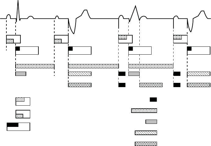
PACING THERAPIES
REFRACTORY 5-59
AV Delay after paced atrial event (programmable,
includes 150 ms absolute refractory)
AV Delay after sensed atrial event (programmable,
includes 85 ms absolute refractory)
Atrial Refractory-PVARP (programmable; includes
programmable atrial cross chamber blank)
V-A interval (may be lengthened
by modified ventricular timing)
RV Sensed Refractory (135 ms)
RV Dynamic Ventricular Refractory
(programmable)
Ventricular Cross Chamber Blank
(programmable)
LV Refractory (programmable)
A sensed
RV sensed
A sensed
BiV paced
A paced
RV sensed
LV sensed
A paced
BiV paced
ECG
Atrial Channel
RV Channel
LV Channel
Figure 5-24. Refractory periods, dual-chamber pacing modes; BiV
- DRAFT -
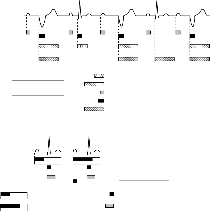
5-60 PACING THERAPIES
NOISE RESPONSE
A sensed*
RV paced
A sensed*
RV sensed
A sensed*
BiV paced
ECG
Atrial Channel
RV Channel
Atrial Sensed Refractory (85 ms)
RV Sensed Refractory (135 ms)
RV Refractory (programmable)
Atrial Cross Chamber Blank (programmable)
* An atrial sense occurs during VVI
if an atrial feature is programmed
on (e.g., atrial electrograms).
LV Channel
LV Refractory (programmable)
A sensed*
LV sensed
A sensed*
LV paced
Figure 5-25. Refractory periods, VVI pacing modes; LV only
Sensed Atrial Refractory-PVARP (programmable;
includes 85 ms absolute refractory)
RV Sensed Refractory (135 ms)
Cross Chamber Blank (programmable
atrial and RV)
Paced Atrial Refractory-PVARP (programmable;
includes 150 ms absolute refractory)
ECG
Atrial Sensing
Ventricular Sensing
A sensed
RV sensed*
A paced
RV sensed*
* An RV sense occurs during AAI
pacing due to the tachycardia
function of the pulse generator.
Figure 5-26. Refractory periods, AAI pacing mode
NOISE RESPONSE
Noise Response allows you to choose whether to pace or inhibit pacing in
the presence of noise.
- DRAFT -
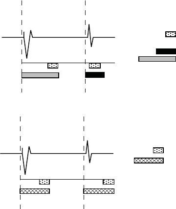
PACING THERAPIES
NOISE RESPONSE 5-61
A retriggerable, 40-ms noise window exists within each refractory and
cross-chamber blanking period. The window is initiated by either a sensed
or paced event. Both the noise window and the refractory period must be
completed for each cardiac cycle in one chamber before the next sensed
event restarts the timing in the same chamber. Recurrent noise activity may
cause the noise window to restart, extending the noise window and possibly
the effective refractory period or blanking period.
The Inhibit mode is intended for patients whose arrhythmias may be triggered by
asynchronous pacing. If Noise Response is programmed to an asynchronous
mode and the noise persists so that the noise window is extended longer
than the programmed pacing escape interval, the pulse generator paces
asynchronously at the programmed pacing rate until the noise ceases.
Refer to Figure 5-27 on page 5-61 and Figure 5-28 on page 5-61.
ECG
RV Sensing
RV Paced
event
RV Sensed
event
Noise window (40 ms)
RV Refractory:
sensed = nonprogrammable
paced = programmable
Figure 5-27. Refractory periods and noise windows, RV
ECG
LV Sensing
LV Paced
event
LV Sensed
event
Noise window (40 ms)
LV Refractory
(programmable)
Figure 5-28. Refractory periods and noise windows, LV
If Noise Response is programmed to Inhibit, and the sensed noise extends the
noise window beyond the programmed paced or sensed interval, the pace
escape interval timing will reset and the pulse generator will not pace until
one escape interval after the noise ceases. The pulse generator will continue
to use a retriggerable noise window. In addition, a Dynamic Noise algorithm
is intended to automatically adjust the maximum sensitivity to avoid noise
detection. This algorithm is active in all rate channels.
- DRAFT -
5-62 PACING THERAPIES
VENTRICULAR TACHY SENSING INTERACTIONS
If event markers are being transmitted, depending on the chamber where noise
is occurring, the marker [AS], [RVS], or [LVS] will occur when the noise window
is triggered, followed by the marker AN, RVN, or LVN if the noise window is
retriggered for 340 ms. The AN, RVN, or LVN marker will occur frequently if the
noise window continuously retriggers for 340 ms.
NOTE: In pacer-dependent patients, use care when considering setting Noise
Response to Inhibit as pacing will not occur.
VENTRICULAR TACHY SENSING INTERACTIONS
Refractory periods and blanking intervals are an integral part of the pulse
generator sensing system. They are used to efficiently suppress detection of
pulse generator artifacts (e.g., a pace or shock) and certain intrinsic signal
artifacts (e.g., a T-wave or far-field R-wave). The pulse generator does not
discriminate between events that occur during refractory periods and blanking
intervals. As a result, all events (pulse generator artifacts, intrinsic artifacts, and
intrinsic events) that occur during a refractory period or blanking interval are
ignored for purposes of pacing timing cycles and ventricular tachy detection.
Certain programmed combinations of pacing parameters are known to interfere
with ventricular tachy detection. When an intrinsic beat from a VT occurs during
a pulse generator refractory period, the VT beat will not be detected. As a
result, detection and therapy of the arrhythmia may be delayed until enough VT
beats are detected to satisfy the tachy detection criteria ("Ventricular Detection
Windows" on page 3-13).
Pacing Parameter Combination Examples
The following examples illustrate the effects of certain pacing parameter
combinations on ventricular sensing. When programming pulse generator
pacing and tachy detection parameters, consider the possible interactions of
these features in light of the expected arrhythmias. In general, the PRM screen
displays Parameter Interaction Attentions and advisory messages to inform you
about programming combinations that could interact to cause these scenarios;
the interactions can be resolved by reprogramming the pacing rate, AV Delay
and/or refractory/blanking periods.
Example 1: Ventricular Undersensing Due to Ventricular Refractory Period
If the pulse generator is programmed as follows, a VT that occurs synchronous
with the pacing will not be detected:
• Brady Mode = VVI
- DRAFT -
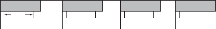
PACING THERAPIES
VENTRICULAR TACHY SENSING INTERACTIONS 5-63
• LRL = 75 ppm (800 ms)
•VRP=500ms
• VT Zone = 150 bpm (400 ms)
In this scenario, the pulse generator is VVI pacing at LRL (800 ms). A 500 ms
VRP follows each ventricular pace. VT beats that occur during VRP are ignored
for purposes of pacemaker timing and ventricular tachy detection/therapy. If
a stable VT of 400 ms starts simultaneously with a ventricular pace, the VT
will not be detected because every beat will occur during the 500 ms VRP,
either concurrent with a ventricular pace or 400 ms after a pace (Figure 5-29 on
page 5-63).
NOTE: It is not required for the VT to start concurrently with a pace for
undersensing to occur. In this example, all pacing will be inhibited and tachy
detection will subsequently occur, as soon as a single VT beat is detected.
VP VP VP VP
(VT) (VT) (VT) (VT) (VT) (VT) (VT)
VRP = 500 ms
400 ms
LRL = 800 ms
Figure 5-29. Ventricular undersensing due to VRP
When the programming interaction described in this scenario is present, a
message will describe the interaction of VRP with LRL. In rate-responsive or
tracking modes (e.g., DDDR), similar messages may describe the interaction
of VRP with MTR, MSR, or MPR. Along with each message, the pertinent
programmable parameters are displayed to assist you in resolving the
interaction. Programming Dynamic VRP can be useful in resolving these
types of interactions.
Example 2: Ventricular Undersensing Due To V-Blank After A-Pace
Certain programmed combinations of dual-chamber pacing parameters may
also interfere with ventricular tachy detection. When dual-chamber pacing
occurs, pulse generator refractory periods are initiated by both atrial and
ventricular paces. The ventricular refractory period following a ventricular pace
is controlled by the VRP parameter; the ventricular refractory period following
an atrial pace is controlled by the V-Blank After A-Pace parameter.
- DRAFT -
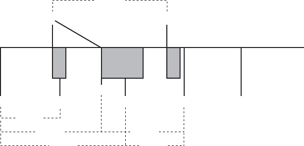
5-64 PACING THERAPIES
VENTRICULAR TACHY SENSING INTERACTIONS
Undersensing of a VT due to the pulse generator refractory periods may occur
when the pulse generator is pacing at or above LRL. For example, if the pulse
generator is rate-adaptive pacing at 100 ppm (600 ms) and is programmed
as follows, then a VT that occurs synchronous with the pacing may not be
detected:
• LRL = 90 ppm (667 ms), MTR/MSR = 130 ppm (460 ms)
• Brady Mode = DDDR, fixed AV delay = 300 ms
•VRP=230ms
• V-Blank After A-Pace = 65 ms
• VT zone = 150 bpm (400 ms)
In this scenario, the pulse generator is DDDR pacing at 600 ms. A VRP of
230 ms follows each ventricular pace; a ventricular refractory period of 65 ms
(V-Blank After A-Pace) follows each atrial pace; an atrial pace occurs 300
ms after each ventricular pace. VT beats that occur during either refractory
period are ignored for purposes of pacemaker timing and ventricular tachy
detection/therapy. If a stable VT of 350 ms starts, then the VT will not be
detected because most beats will occur during a ventricular refractory period,
either V-Blank After A-Pace or VRP. Some VT beats will be detected, but not
enough to satisfy the 8 of 10 tachy detection criteria ("Ventricular Detection
Windows" on page 3-13).
NOTE: It is not required for the VT to start concurrently with a refractory
period or blanking interval for undersensing to occur. In this example, it is likely
that the VT will not be detected until either the VT accelerates to faster than
350 ms or the sensor-driven pacing rate changes from 600 ms.
VT (VT) (VT) VTVS*
APAP AV = 300 ms
VRP
230 ms
VP
600 ms
350 ms
350 ms700 ms
600 ms 450 ms
Repeat pattern
AP, VP, AP, VS, VT
Figure 5-30. Ventricular undersensing due to V-Blank after A-Pace
- DRAFT -