Boston Scientific CRMN11906 Implantable Defibrillator User Manual Teligen Part 1 Manual
Boston Scientific Corporation Implantable Defibrillator Teligen Part 1 Manual
Contents
Teligen Part 1 Manual

SYSTEM GUIDE
TELIGEN™100
IMPLANTABLE CARDIOVERTER HIGH ENERGY
DEFIBRILLATOR
REF E102, E110
CAUTION: Federal law
restricts this device to sale by
or on the order of a physician
trained or experienced in
device implant and follow-up
procedures. Part 1 of 2
- DRAFT -
- DRAFT -

ABOUT THIS MANUAL
Boston Scientific Corporation acquired Guidant Corporation in April 2006.
During our transition period, you may see both the Boston Scientificand
Guidant names on product and patient material. As we work through the
transition, we will continue to offer doctors and their patients technologically
advanced and high quality medical devices and therapies.
The text conventions discussed below are used throughout this manual.
PRM KEYS The names of Programmer/Recorder/Monitor (PRM)
keys appear in capital letters (e.g., PROGRAM,
INTERROGATE).
1., 2., 3. Numbered lists are used for instructions that should be
followed in the order given.
•Bulleted lists are used when the information is not
sequential.
This product family includes single- and dual-chamber models, with feature
variations. This manual is written for full description of a full-featured model
(e.g., a dual-chamber model with ZIP telemetry). Some models will contain
fewer features; for those devices, disregard descriptions of the unavailable
features.
The screen illustrations used in this manual are intended to familiarize you with
the general screen layout. The actual screens you see when interrogating
or programming the pulse generator will vary based on the model and
programmed parameters.
A complete list of programmable options is provided in the appendix
("Programmable Options" on page A-1). The actual values you see when
interrogating or programming the pulse generator will vary based on the model
and programmed parameters.
ThefollowingacronymsmaybeusedinthisSystemGuide:
A: Atrial
AF: Atrial Fibrillation
The following are trademarks of Boston Scientificoritsaffiliates: ENDOTAK, RHYTHM ID,
TELIGEN, VENTAK, VITALITY, ZIP.
- DRAFT -
AFib: Atrial Fibrillation
AFR: Atrial Flutter Response
AGC: Automatic Gain Control
AIVR: Accelerated Idioventricular Rhythm
AT: Atrial Tachycardia
ATP: Antitachycardia Pacing
ATR: Atrial Tachy Response
AV: Atrioventricular
BCL: Burst Cycle Length
BOL: Beginning of Life
CPR: Cardiopulmonary Resuscitation
ECG: Electrocardiogram
DFT: Defibrillation Threshold
EAS: Electronic Article Surveillance
EF: Ejection Fraction
EGM: Electrogram
EMI: Electromagnetic Interference
EP: Electrophysiology; Electrophysiologic
FCC: Federal Communications Commission
HE: High Energy
IBP: Indications-Based Programming
IC: Industry Canada
ICD: Implantable Cardioverter Defibrillator
LRL: Lower Rate Limit
MI: Myocardial Infarction
MPR: Maximum Pacing Rate
MRI: Magnetic Resonance Imaging
MSR: Maximum Sensor Rate
MTR: Maximum Tracking Rate
NSR: Normal Sinus Rhythm
PAC: Premature Atrial Contraction
PAT: Paroxysmal Atrial Tachycardia
PES: Programmed Electrical Stimulation
PMT: Pacemaker-Mediated Tachycardia
PRM: Programmer/Recorder/Monitor
PSA: Pacing System Analyzer
PVARP: Post-Ventricular Atrial Refractory Period
PVC: Premature Ventricular Contraction
RADAR: Radio Detection and Ranging
RF: Radio Frequency
RV: Right Ventricular
RVRP: Right Ventricular Refractory Period
SCD: Sudden Cardiac Death
- DRAFT -
SRD: Sustained Rate Duration
SVT: Supraventricular Tachycardia
TARP: Total Atrial Refractory Period
TENS: Transcutaneous Electrical Nerve Stimulation
V: Ventricular
VFib: Ventricular Fibrillation
VF: Ventricular Fibrillation
VRP: Ventricular Refractory Period
VRR: Ventricular Rate Regulation
VT: Ventricular Tachycardia
VTR: Ventricular Tachycardia Response
- DRAFT -
- DRAFT -
CONTENTS
INFORMATION FOR USE ................................................................................................. 1-1
CHAPTER 1
New or Enhanced Features................................................................................................ 1-3
Device Description.............................................................................................................. 1-4
Related Information ............................................................................................................ 1-6
Indications and Usage ........................................................................................................ 1-6
Contraindications................................................................................................................ 1-6
Warnings ............................................................................................................................ 1-7
Precautions......................................................................................................................... 1-8
Potential Adverse Events ................................................................................................. 1-18
Mechanical Specifications ................................................................................................ 1-19
Lead Connections............................................................................................................. 1-20
Items Included in Package ............................................................................................... 1-21
Symbols on Packaging ..................................................................................................... 1-21
Characteristics as Shipped............................................................................................... 1-22
X-Ray Identifier................................................................................................................. 1-23
Federal Communications Commission (FCC) .................................................................. 1-24
Industry Canada (IC) ........................................................................................................ 1-24
Pulse Generator Longevity ............................................................................................... 1-25
Warranty Information ........................................................................................................ 1-26
Product Reliability............................................................................................................. 1-26
- DRAFT -
Patient Counseling Information ........................................................................................ 1-27
Patient Handbook ...................................................................................................... 1-28
USING THE PROGRAMMER/RECORDER/MONITOR..................................................... 2-1
CHAPTER 2
ZOOM LATITUDE Programming System ........................................................................... 2-2
Indications-Based Programming (IBP) ............................................................................... 2-2
Manual Programming ......................................................................................................... 2-5
Software Terminology and Navigation ................................................................................ 2-6
Main Screen................................................................................................................. 2-6
PRM Mode Indicator .................................................................................................... 2-6
ECG/EGM Display ....................................................................................................... 2-7
Toolbar .........................................................................................................................2-8
Tabs ............................................................................................................................. 2-8
Buttons.........................................................................................................................2-8
Icons ............................................................................................................................ 2-8
Common Objects ....................................................................................................... 2-10
Use of Color ............................................................................................................... 2-10
Data Management ............................................................................................................ 2-11
Patient Information..................................................................................................... 2-11
Disk Operations ......................................................................................................... 2-11
Print............................................................................................................................ 2-12
Communicating with the Pulse Generator ........................................................................ 2-12
ZIP Telemetry............................................................................................................. 2-13
Starting a Wanded Telemetry Session ....................................................................... 2-13
Starting a ZIP Telemetry Session............................................................................... 2-14
Ending a Telemetry Session ...................................................................................... 2-14
ZIP Telemetry Security............................................................................................... 2-14
DIVERT THERAPY .......................................................................................................... 2-17
STAT SHOCK ................................................................................................................... 2-17
STAT PACE ...................................................................................................................... 2-18
Safety Mode ..................................................................................................................... 2-19
Backup Pacemaker.................................................................................................... 2-19
- DRAFT -
Backup Defibrillator.................................................................................................... 2-19
Programming the Device Safety Tachy Mode ............................................................ 2-20
TACHYARRHYTHMIA DETECTION.................................................................................. 3-1
CHAPTER 3
Device Mode....................................................................................................................... 3-2
Ventricular Tachy Mode................................................................................................ 3-2
Electrocautery Protection Mode................................................................................... 3-3
Rate Sensing...................................................................................................................... 3-3
Calculating Rates and Refractory Periods ................................................................... 3-4
Ventricular Rate Thresholds and Zones....................................................................... 3-4
Use of Atrial Information .............................................................................................. 3-5
Ventricular Detection .......................................................................................................... 3-6
Ventricular Detection Enhancement Suites.................................................................. 3-7
Ventricular Redetection.............................................................................................. 3-11
Ventricular Post-shock Detection Enhancements ...................................................... 3-11
Ventricular Detection Details...................................................................................... 3-12
TACHYARRHYTHMIA THERAPY ..................................................................................... 4-1
CHAPTER 4
Ventricular Therapy ............................................................................................................ 4-2
Ventricular Therapy Prescription.................................................................................. 4-2
Ventricular Therapy Selection ...................................................................................... 4-3
Ventricular Redetection after Ventricular Therapy Delivery ......................................... 4-8
Ventricular Redetection after Ventricular ATP Therapy................................................ 4-8
Ventricular Redetection after Ventricular Shock Therapy ............................................ 4-9
Antitachycardia Pacing Therapies and Parameters ......................................................... 4-10
Burst Parameters ....................................................................................................... 4-11
Coupling Interval and Coupling Interval Decrement .................................................. 4-12
Burst Cycle Length (BCL) .......................................................................................... 4-14
Minimum Interval........................................................................................................ 4-14
Burst Scheme ............................................................................................................ 4-15
Ramp Scheme ........................................................................................................... 4-15
Scan Scheme............................................................................................................. 4-16
Ramp/Scan Scheme .................................................................................................. 4-17
ATP Pulse Width and ATP Amplitude ........................................................................ 4-18
Ventricular ATP Time-out ........................................................................................... 4-19
QUICK CONVERT ATP ............................................................................................. 4-20
- DRAFT -
Ventricular Shock Therapy and Parameters..................................................................... 4-21
Ventricular Shock Vector............................................................................................ 4-21
Ventricular Shock Energy........................................................................................... 4-21
Charge Time .............................................................................................................. 4-22
Waveform Polarity...................................................................................................... 4-22
Committed Shock/Reconfirmation of the Ventricular Arrhythmia ............................... 4-23
PACING THERAPIES ........................................................................................................ 5-1
CHAPTER 5
Pacing Therapies................................................................................................................ 5-2
Basic Parameters ............................................................................................................... 5-2
Brady Mode.................................................................................................................. 5-3
Lower Rate Limit (LRL) ................................................................................................ 5-4
Maximum Tracking Rate (MTR) ................................................................................... 5-5
Maximum Sensor Rate (MSR) ..................................................................................... 5-6
Pulse Width.................................................................................................................. 5-7
Amplitude ..................................................................................................................... 5-8
Sensitivity.....................................................................................................................5-8
Post-Therapy Pacing .......................................................................................................... 5-9
Post-Shock Pacing Delay ............................................................................................ 5-9
Post-Therapy Period .................................................................................................. 5-10
Temporary Pacing............................................................................................................. 5-10
Sensors and Trending ...................................................................................................... 5-11
Sensor Trending......................................................................................................... 5-11
Adaptive-rate Pacing.................................................................................................. 5-12
Accelerometer............................................................................................................ 5-13
Atrial Tachy Response...................................................................................................... 5-19
ATR Mode Switch ...................................................................................................... 5-19
Ventricular Rate Regulation (VRR) ............................................................................ 5-24
Atrial Flutter Response (AFR) .................................................................................... 5-25
PMT Termination........................................................................................................ 5-25
Rate Enhancements ......................................................................................................... 5-26
Rate Hysteresis.......................................................................................................... 5-26
Rate Smoothing ......................................................................................................... 5-28
Lead Configuration ........................................................................................................... 5-31
- DRAFT -
AV Delay........................................................................................................................... 5-32
Paced AV Delay ......................................................................................................... 5-32
Sensed AV Delay ....................................................................................................... 5-33
AV Search+ ................................................................................................................ 5-35
Refractory ......................................................................................................................... 5-36
A-Refractory (PVARP) ............................................................................................... 5-36
RV-Refractory (RVRP) ............................................................................................... 5-37
Blanking and Noise Rejection .................................................................................... 5-38
Noise Response ............................................................................................................... 5-41
Ventricular Tachy Sensing Interactions............................................................................. 5-43
SYSTEM DIAGNOSTICS................................................................................................... 6-1
CHAPTER 6
Battery Status ..................................................................................................................... 6-2
Capacitor Re-formation................................................................................................ 6-5
Charge Time Measurement ......................................................................................... 6-5
Last Delivered Ventricular Shock ................................................................................. 6-6
Lead Tests .......................................................................................................................... 6-6
Intrinsic Amplitude Test ................................................................................................ 6-7
Lead Impedance Test................................................................................................... 6-8
Pace Threshold Test .................................................................................................... 6-8
PATIENT DIAGNOSTICS................................................................................................... 7-1
CHAPTER 7
Therapy History ..................................................................................................................7-2
Trends ................................................................................................................................ 7-3
Arrhythmia Logbook ........................................................................................................... 7-5
Histograms................................................................................................................. 7-11
Counters .................................................................................................................... 7-11
Patient Triggered Monitor ................................................................................................. 7-13
- DRAFT -
ELECTROPHYSIOLOGIC TESTING................................................................................. 8-1
CHAPTER 8
EP Test Features ................................................................................................................ 8-2
Temporary EP Mode .................................................................................................... 8-2
Backup Ventricular Pacing During Atrial EP Testing .................................................... 8-2
EP Test Screen ............................................................................................................ 8-2
Induction Methods .............................................................................................................. 8-4
VFib Induction .............................................................................................................. 8-5
Shock on T Induction ................................................................................................... 8-6
Programmed Electrical Stimulation (PES) ................................................................... 8-7
50 Hz/Manual Burst Pacing ......................................................................................... 8-9
Commanded Therapy Methods ........................................................................................ 8-10
Commanded Shock ................................................................................................... 8-10
Commanded ATP....................................................................................................... 8-11
IMPLANT INFORMATION ................................................................................................. 9-1
CHAPTER 9
Implanting the Pulse Generator.......................................................................................... 9-2
Step A: Check Equipment ......................................................................................... 9-2
Step B: Interrogate and Check the Pulse Generator................................................. 9-3
Step C: Implant the Lead System.............................................................................. 9-3
Step D: Take Baseline Measurements ...................................................................... 9-4
Step E: Form the Implantation Pocket....................................................................... 9-5
Step F: Connect the Leads to the Pulse Generator .................................................. 9-6
Step G: Evaluate Lead Signals ................................................................................. 9-9
Step H: Program the Pulse Generator .................................................................... 9-10
Step I: Implant the Pulse Generator ........................................................................ 9-10
Step J: Complete and Return the Implantation Form .............................................. 9-11
POST IMPLANT INFORMATION..................................................................................... 10-1
CHAPTER 10
Follow Up Testing ............................................................................................................. 10-2
Predischarge Follow Up ............................................................................................. 10-2
Routine Follow Up...................................................................................................... 10-2
Post Implant features........................................................................................................ 10-3
Sensitivity Adjustment................................................................................................ 10-3
Beeper Feature .......................................................................................................... 10-4
- DRAFT -
Magnet Feature.......................................................................................................... 10-5
Explantation...................................................................................................................... 10-8
PROGRAMMABLE OPTIONS........................................................................................... A-1
APPENDIX A
PACEMAKER INTERACTION ........................................................................................... B-1
APPENDIX B
CLINICAL STUDY - MADIT II ............................................................................................ C-1
APPENDIX C
Summary ............................................................................................................................ C-1
Indications for Use.............................................................................................................. C-1
Observed Adverse Events.................................................................................................. C-1
Mortality .............................................................................................................................. C-6
Summary of Clinical Study ................................................................................................. C-6
Study Design ...................................................................................................................... C-7
Inclusion/Exclusion Criteria ................................................................................................ C-8
Patient Status ...................................................................................................................C-10
Primary Endpoint .............................................................................................................. C-10
Follow-up Schedule .......................................................................................................... C-11
Study Results ................................................................................................................... C-12
CLINICAL STUDY - VENTAK AV II DR ............................................................................. D-1
APPENDIX D
Clinical Study Populations .................................................................................................. D-1
Chronic Implant Study - VENTAK AV II DR ........................................................................ D-1
- DRAFT -
CLINICAL STUDY - VITALITY........................................................................................... E-1
APPENDIX E
Clinical Study Populations .................................................................................................. E-1
Chronic Implant Study - VITALITY...................................................................................... E-1
Acute Study - VITALITY...................................................................................................... E-3
CLINICAL STUDY - SUMMARY OF GDT1000 SENSING ACUTE STUDY...................... F-1
APPENDIX F
Clinical Study Populations .................................................................................................. F-1
Study Methods....................................................................................................................F-1
Study Results ..................................................................................................................... F-3
Conclusions........................................................................................................................ F-7
- DRAFT -

1-1
INFORMATION FOR USE
CHAPTER 1
This chapter contains the following topics:
• "New or Enhanced Features" on page 1-3
• "Device Description" on page 1-4
• "Related Information" on page 1-6
• "Indications and Usage" on page 1-6
• "Contraindications" on page 1-6
• "Warnings" on page 1-7
• "Precautions" on page 1-8
• "Potential Adverse Events" on page 1-18
• "Mechanical Specifications" on page 1-19
• "Lead Connections" on page 1-20
• "Items Included in Package" on page 1-21
• "Symbols on Packaging" on page 1-21
• "Characteristics as Shipped" on page 1-22
• "X-Ray Identifier" on page 1-23
• "Federal Communications Commission (FCC)" on page 1-24
• "Industry Canada (IC)" on page 1-24
• "Pulse Generator Longevity" on page 1-25
• "Warranty Information" on page 1-26
• "Product Reliability" on page 1-26
- DRAFT -
1-2 INFORMATION FOR USE
• "Patient Counseling Information" on page 1-27
- DRAFT -
1-3
NEW OR ENHANCED FEATURES
These pulse generator systems include additional features as compared to
previous products.
Ease of Use
• ZOOMVIEW Programmer Software: the new user interface offers the
following benefits:
– Clinical focus—features such as patient diagnostic trends and
indications-based programming emphasize the patient’s clinical
condition over device status and parameters.
– Consistency—ZOOMVIEW software will be available on future pulse
generators, providing the same screens whether you are following a
brady, tachy, or heart failure device.
– Simplicity—screen complexity is reduced through the use of
progressive disclosure (displaying the information you use frequently
and minimizing the information you only rarely access) and
exception-based reporting.
• Indications-Based Programming (IBP): the new ZOOMVIEW feature allows
you to quickly set up programming parameters based on the patient’s
clinical needs and indications.
Tachy Therapy
• Rhythm ID and Onset/Stability detection: the selection between detection
enhancements provides you the opportunity and flexibility to adjust for
individual patient conditions.
• QUICK CONVERT ATP: in an attempt to avoid an otherwise scheduled
charge and painful shock for a pace-terminable fast ventricular tachycardia
(VT), the pulse generator delivers one rapid burst of antitachycardia pacing
(ATP) for an episode detected in the ventricular fibrillation (VF) zone.
• Programmable Shock Vectors: this capability allows you to electronically
change the shocking vectors for added flexibility in treating high
defibrillation thresholds (DFTs).
- DRAFT -
1-4 INFORMATION FOR USE
DEVICE DESCRIPTION
Brady Therapy
• AV Search +: this feature is designed to reduce unnecessary RV pacing for
patients with intact or intermittent AV conduction by allowing intrinsic AV
conduction beyond the programmed AV delay during episodes of normal
AV nodal function—an enhanced version of AV Search Hysteresis.
Sensing
• Sensing is designed to combine the strengths of both implantable
cardioverter defibrillator (ICD) and pacemaker sensing capabilities to
improve detection and therapy by reducing inappropriate mode switching,
pacing inhibition, and shocks.
DEVICE DESCRIPTION
This manual contains information about the TELIGEN 100 family of implantable
cardioverter defibrillators (ICDs). The TELIGEN 100 family contains the
following types of pulse generators (specific models are listed in "Mechanical
Specifications" on page 1-19):
• VR—single-chamber ICD combining ventricular tachyarrhythmia therapy
with ventricular pacing and sensing
• DR—dual-chamber ICD combining ventricular tachyarrhythmia therapy
with ventricular and atrial pacing and sensing
Therapies
This family of pulse generators has a small, thin, physiologic shape that
minimizes pocket size and may minimize device migration. Pulse generators
within this family provide a variety of therapies, including:
• Ventricular tachyarrhythmia therapy, which is used to treat rhythms
associated with sudden cardiac death (SCD) such as VT and VF
• Bradycardia pacing, including adaptive rate pacing, to detect and treat
bradyarrhythmias and to provide cardiac rate support after defibrillation
therapy
Cardioversion/defibrillation therapies include:
• A range of low- and high-energy shocks using a biphasic waveform
- DRAFT -
INFORMATION FOR USE
DEVICE DESCRIPTION 1-5
• The choice of multiple shock vectors:
– Distal shock electrode to proximal shock electrode and pulse generator
case (TRIAD electrode system)
– Distal shock electrode to proximal shock electrode (RV Coil to RA Coil)
– Distal shock electrode to pulse generator case (RV Coil to Can)
Leads
The pulse generator has independently programmable outputs and accepts
the following leads:
•OneIS-1
1atrial lead
•OneDF-1/IS-1
2cardioversion/defibrillation lead
The pulse generator and the leads constitute the implantable portion of the
pulse generator system.
PRM System
These pulse generators can be used only with the ZOOM LATITUDE
Programming System, which is the external portion of the pulse generator
system and includes:
• Model 3120 Programmer/Recorder/Monitor (PRM)
• Model 2868 ZOOMVIEW Software Application
• Model 6577 Accessory Telemetry Wand
YoucanusethePRMsystemtodothefollowing:
• Interrogate the pulse generator
• Program the pulse generator to provide a variety of therapy options
• Access the pulse generator’s diagnostic features
• Perform noninvasive diagnostic testing
• Access therapy history data
1. IS-1 refers to the international standard ISO 5841.3:2000.
2. DF-1 refers to the international standard ISO 11318:2002.
- DRAFT -
1-6 INFORMATION FOR USE
RELATED INFORMATION
RELATED INFORMATION
Refer to the lead’s instruction manual for implant information, general warnings
and precautions, indications, contraindications, and technical specifications.
Read this material carefully for implant procedure instructions specifictothe
chosen lead configurations.
The Physician’s Technical Manual is packaged with the pulse generator. It
provides the technical information needed at implant.
Refer to the PRM system Operator’s Manual for specific information about the
PRM such as setup, maintenance, and handling.
INDICATIONS AND USAGE
Boston Scientific implantable cardioverter defibrillators (ICDs) are intended to
provide ventricular antitachycardia pacing (ATP) and ventricular defibrillation
for automated treatment of life-threatening ventricular arrhythmias.
CONTRAINDICATIONS
These Boston Scientific pulse generators are contraindicated for the following
patients:
• Patients whose ventricular tachyarrhythmias may have reversible cause,
such as:
– Digitalis intoxication
– Electrolyte imbalance
– Hypoxia
–Sepsis
• Patients whose ventricular tachyarrhythmias have a transient cause, such
as:
– Acute myocardial infarction (MI)
– Electrocution
–Drowning
• Patients who have a unipolar pacemaker
- DRAFT -
INFORMATION FOR USE
WARNINGS 1-7
WARNINGS
General
• Labeling knowledge. Read this manual thoroughly before implanting the
pulse generator to avoid damage to the system. Such damage can result in
patient injury or death.
• Avoid shock during handling. Program the pulse generator Tachy
Mode(s) to Off during implant, explant, or postmortem procedures to avoid
inadvertent high voltage shocks.
• Backup defibrillation protection. Always have sterile external and
internal defibrillation protection available during implant. If not terminated in
a timely fashion, an induced ventricular tachyarrhythmia can result in the
patient’s death.
• Resuscitation availability. Ensure that an external defibrillator and
medical personnel skilled in CPR are present during post-implant device
testing should the patient require external rescue.
• Protected environments. Advise patients to seek medical guidance
before entering environments that could adversely affect the operation
of the active implantable medical device, including areas protected by a
warning notice that prevents entry by patients who have a pulse generator.
• Magnetic Resonance Imaging (MRI) exposure. Do not expose a patient
to MR device scanning. Strong magnetic fields may damage the device
and cause injury to the patient.
•Diathermy.Do not subject a patient with an implanted pulse generator
to diathermy since diathermy may cause fibrillation, burning of the
myocardium, and irreversible damage to the pulse generator because of
induced currents.
Programming and Device Operations
• Atrial tracking modes. Do not use atrial tracking modes in patients with
chronic refractory atrial tachyarrhythmias. Tracking of atrial arrhythmias
could result in VT or VF.
- DRAFT -
1-8 INFORMATION FOR USE
PRECAUTIONS
Implant Related
• Do not kink leads. Kinking leads may cause additional stress on the
leads, possibly resulting in lead fracture.
• Separate pulse generator. Do not use this pulse generator with another
pulse generator. This combination could cause pulse generator interaction,
resulting in patient injury or a lack of therapy delivery.
PRECAUTIONS
Clinical Considerations
• Pacemaker-mediated tachycardia (PMT). Retrograde conduction
combined with a short PVARP might induce PMT.
Sterilization, Storage, and Handling
• For single use only; do not resterilize devices. Do not resterilize the
device or the accessories packaged with it because the effectiveness of
resterilization cannot be ensured.
• If package is damaged. The pulse generator blister trays and contents
are sterilized with ethylene oxide gas before final packaging. When the
pulse generator is received, it is sterile provided the container is intact. If
the packaging is wet, punctured, opened, or otherwise damaged, return the
device to Boston Scientific.
• Storage temperature and equilibration. Recommended storage
temperatures are 0°C–50°C (32°F–122°F). Allow the device to reach a
proper temperature before using telemetry communication capabilities,
programming or implanting the device because temperature extremes may
affect initial device function.
•Devicestorage.Store the pulse generator in a clean area away from
magnets, kits containing magnets, and sources of EMI to avoid device
damage.
•Usebydate.Implant the device system before or on the USE BY date on
the package label because this date reflects a validated shelf life. For
example, if the date is January 1, do not implant on or after January 2.
- DRAFT -
INFORMATION FOR USE
PRECAUTIONS 1-9
Implantation and Device Programming
• Lead system. Do not use any lead with this device without first verifying
connector compatibility. Using incompatible leads can damage the
connector and/or result in potential adverse consequences, such as
undersensing of cardiac activity or failure to deliver necessary therapy.
• Telemetry wand. Make sure the telemetry wand is connected to the
programmer and that it is available throughout the session. Verify that the
wand cord is within reach of the pulse generator.
•STATPACEsettings.When a pulse generator is programmed to STAT
PACE settings, it will continue to pace at the high-energy STAT PACE
values if it is not reprogrammed. The use of STAT PACE parameters will
decrease device longevity.
• Pacing and sensing margins. Consider lead maturation in your choice of
pacing amplitude, pacing pulse width, and sensitivity settings.
• An acute pacing threshold greater than 1.5 V or a chronic pacing
threshold greater than 3 V can result in loss of capture because
thresholds may increase over time.
• An R-wave amplitude less than 5 mV or a P-wave amplitude less than
2 mV can result in undersensing because the sensed amplitude may
decrease after implantation.
• Pacing lead impedance should be within the range of 200 and
2000 .
• Line-powered equipment. Exercise extreme caution if testing leads using
line-powered equipment because leakage current exceeding 10 µA can
induce ventricular fibrillation. Ensure that any line-powered equipment is
within specifications.
• Proper programming of the shock vector. If the shock vector is
programmed to RVcoil>>RAcoil and the lead does not have an RA coil,
shocking will not occur.
• Replacement device. Implanting a replacement device in a subcutaneous
pocket that previously housed a larger device may result in pocket air
entrapment, migration, erosion, or insufficient grounding between the
device and tissue. Irrigating the pocket with sterile saline solution decreases
the possibility of pocket air entrapment and insufficient grounding. Suturing
the device in place reduces the possibility of migration and erosion.
- DRAFT -
1-10 INFORMATION FOR USE
PRECAUTIONS
•Defibrillation power surge. Defibrillation that causes a power surge
exceeding 360 watt-seconds can damage the pulse generator system.
• Programming for supraventricular tachyarrhythmias (SVTs).
Determine if the device and programmable options are appropriate for
patients with SVTs because SVTs can initiate unwanted device therapy.
• Ventricular refractory periods (VRPs) in adaptive-rate pacing.
Adaptive-rate pacing is not limited by refractory periods. A long refractory
period programmed in combination with a high MSR can result in
asynchronous pacing during refractory periods since the combination can
cause a very small sensing window or none at all. Use dynamic AV Delay
or dynamic PVARP to optimize sensing windows. If you are entering a
fixed AV delay, consider the sensing outcomes.
• Do not bend the lead near the lead-header interface. Improper insertion
can cause insulation damage near the terminal end that could result in
lead failure.
• Shock waveform polarity. For IS-1/DF-1 leads, never change the shock
waveform polarity by physically switching the lead anodes and cathodes
in the pulse generator header—use the programmable Polarity feature.
Device damage or nonconversion of the arrhythmia post-operatively may
result if the polarity is switched physically.
• Absence of a lead. The absence of a lead or plug in a lead port may
affect device performance. If a lead is not used, be sure to properly insert
a plug in the unused port.
• Electrode connections. Do not insert a lead into the pulse generator
connector without first visually verifying that the setscrew is sufficiently
retracted to allow insertion. Fully insert each lead into its lead port and then
tighten the setscrew onto the electrodes.
• Tachy Mode to Off. To prevent inappropriate shocks, ensure that the
pulse generator’s Tachy Mode is programmed to Off when not in use
and before handling the device. For tachyarrhythmia therapy, verify that
the Tachy Mode is activated.
- DRAFT -
INFORMATION FOR USE
PRECAUTIONS 1-11
• Atrial oversensing. For dual-chamber models, take care to ensure that
artifacts from the ventricles are not present on the atrial channel, or
atrial oversensing may result. If ventricular artifacts are present in the
atrial channel, the atrial lead may need to be repositioned to minimize its
interaction.
•Defibrillation lead impedance. Neverimplantthedevicewithalead
system that has less than 15 total shock lead impedance. Device
damage may result. If a shocking lead impedance is less than 20 ,
reposition the shocking electrodes to allow a greater distance between the
shocking electrodes.
• ATR entry count. Exercise care when programming the Entry Count to
low values in conjunction with a short ATR Duration. This combination
allows mode switching with very few fast atrial beats. For example, if the
Entry Count was programmed to 2 and the ATR Duration to 0, ATR mode
switching could occur on 2 fast atrial intervals. In these instances, a short
series of premature atrial events could cause the device to mode switch.
• ATR exit count. Exercise care when programming the Exit Count to low
values. For example, if the Exit Count was programmed to 2, a few cycles
of atrial undersensing could cause termination of mode switching.
• Shunting energy. Do not allow any object that is electrically conductive
to come into contact with the lead or device during induction because it
may shunt energy, resulting in less energy getting to the patient, and may
damage the implanted system.
• Expected benefits. Determinewhethertheexpecteddevicebenefits
outweigh the possibility of early device replacement for patients whose
tachyarrhythmias require frequent shocks.
• Device communication. Use only the designated PRM and software
application to communicate with this pulse generator.
- DRAFT -
1-12 INFORMATION FOR USE
PRECAUTIONS
Environmental and Medical Therapy Hazards
• Avoid electromagnetic interference (EMI). Advise patients to avoid
sources of EMI because EMI may cause the pulse generator to deliver
inappropriate therapy or inhibit appropriate therapy. Examples of EMI
sources are:
• Electrical power sources, arc welding equipment, and robotic jacks
• Electrical smelting furnaces
• Large RF transmitters such as radar
• Radio transmitters, including those used to control toys
• Electronic surveillance (antitheft) devices
• An alternator on a car that is running
• Elevated Pressures. Elevated pressures due to hyperbaric chamber
exposure of SCUBA diving may damage the pulse generator. The pulse
generator has been tested to function normally at 1.5 Atmospheres
Absolute (ATA) pressure or 15 ft (4.6 m) depth in sea water. For specific
guidelines prior to hyperbaric chamber exposure, or if the patient is
planning scuba diving activity, contact Technical Services at the number
shown on the back cover of this manual.
Hospital and Medical Environments
• Mechanical ventilators. During mechanical ventilation, respiration rate
trending may be misleading; therefore, the Respiratory Sensor should be
programmed to Off.
• Internal defibrillation. Do not use internal defibrillation paddles or
catheters unless the pulse generator is disconnected from the leads
because the leads may shunt energy. This could result in injury to the
patient and damage to the implanted system.
•Externaldefibrillation. Use of external defibrillation can damage the
pulse generator.
- DRAFT -
INFORMATION FOR USE
PRECAUTIONS 1-13
• Transcutaneous electrical nerve stimulation (TENS). TENS may
interfere with pulse generator function. If necessary, the following measures
may reduce interference:
1. Place the TENS electrodes as close to each other as possible and as
far from the pulse generator and lead system as possible.
2. Monitor cardiac activity during TENS use.
For additional information, contact Technical Services at the number shown
on the back cover of this manual.
• Electrocautery. The use of electrocautery could induce ventricular
arrhythmias and/or fibrillation, cause asynchronous or inhibited pulse
generator operation, or cause the pulse generator to deliver an
inappropriate shock. If electrocautery cannot be avoided, observe the
following precautions to minimize complications:
• Select Electrocautery Protection Mode. Avoid direct contact with the
pulse generator or leads.
• Monitor the patient and have temporary pacing equipment, external
defibrillation equipment, and knowledgeable medical personnel
available.
• Position the ground plate so that the current pathway does not pass
through or near the pulse generator system.
• Use short, intermittent, and irregular bursts at the lowest feasible
energy levels.
• Use a bipolar electrocautery system where possible.
Remember to reactivate the Tachy Mode after turning off the electrocautery
equipment.
- DRAFT -
1-14 INFORMATION FOR USE
PRECAUTIONS
• Ionizing radiation therapy. Ionizing radiation therapy may adversely affect
device operation. During ionizing radiation therapy (e.g., radioactive cobalt,
linear accelerators, and betatrons), the pulse generator must be shielded
with a radiation-resistive material, regardless of the distance of the device
to the radiation beam. Do not project the radiation port directly at the
device. After waiting a minimum of one hour following radiation treatment
(to allow for a device memory check to occur), always evaluate device
operation, including interrogation and sensing and pacing threshold testing.
At the completion of the entire course of treatments, perform device
interrogation and follow-up, including sensing and pacing threshold testing
and capacitor re-formation.
• Lithotripsy. Lithotripsy may permanently damage the pulse generator if
the device is at the focal point of the lithotripsy beam. If lithotripsy must be
used, avoid focusing near the pulse generator site.
The lithotriptor is designed to trigger off the R-wave on the ECG, resulting
in shock waves being delivered during the VRP.
• If the patient does not require pacing, program the pulse generator
Brady Mode to Off.
• If the patient requires pacing, program the pulse generator to the VVI
mode because atrial pacing pulses can trigger the lithotriptor.
• Ultrasound energy. Therapeutic ultrasound (e.g., lithotripsy) energy may
damage the pulse generator. If therapeutic ultrasound energy must be
used, avoid focusing near the pulse generator site. Diagnostic ultrasound
(e.g., echocardiography) is not known to be harmful to the pulse generator.
- DRAFT -
INFORMATION FOR USE
PRECAUTIONS 1-15
• Radio frequency ablation. Exercise caution when performing radio
frequency ablation procedures in device patients. If the pulse generator
Tachy Mode is programmed to Monitor + Therapy during the procedure,
the device may inappropriately declare a tachycardia episode and deliver
therapy. Pacing therapy may also be inhibited unless the device is
programmed to Electrocautery mode. RF ablation may cause changes in
pacing thresholds; evaluate the patient’s thresholds appropriately.
Minimize risks by following these steps:
• Program the Tachy Mode(s) to Electrocautery Protection to avoid
inadvertent tachycardia detection (sensing) or therapy.
• Monitor the patient and have external defibrillation equipment and
knowledgeable medical personnel available.
• Avoid direct contact between the ablation catheter and the implanted
lead and pulse generator.
• Keep the current path (electrode tip to ground) as far away from the
pulse generator and leads as possible.
• Consider the use of external pacing support for pacemaker-dependent
patients (i.e., using internal or external pacing methods).
• Monitor pre- and post-measurements for sensing and pacing thresholds
and impedances to determine the integrity of the lead-patient function.
Remember to reactivate the pulse generator after turning off the radio
frequency ablation equipment.
• Electrical interference. Electrical interference or “noise” from devices
such as electrocautery and monitoring equipment may interfere with
establishing or maintaining telemetry for interrogating or programming the
device. In the presence of such interference, move the programmer away
from electrical devices, and ensure that the wand cord and cables are not
crossing one another. If telemetry is cancelled as a result of interference,
the device should be re-interrogated prior to evaluating information from
pulse generator memory.
- DRAFT -
1-16 INFORMATION FOR USE
PRECAUTIONS
• Radio frequency (RF) interference. RF signals from devices that
operate at frequencies near that of the pulse generator may interrupt ZIP
telemetry while interrogating or programming the pulse generator. This
RF interference can be reduced by increasing the distance between the
interfering device and the PRM and pulse generator. Examples of devices
that may cause interference include:
• Cordless phone handsets or base stations
• Certain patient monitoring systems
• Remote control toys
Home and Occupational Environments
• Home appliances. Home appliances that are in good working order and
properly grounded do not usually produce enough EMI to interfere with
pulse generator operation. There have been reports of pulse generator
disturbances caused by electric hand tools or electric razors used directly
over the pulse generator implant site.
• Magnetic fields. Advise patients that extended exposure to strong (greater
than 10 gauss or 1 mTesla) magnetic fields may trigger the magnet feature.
Examples of magnetic sources include:
• Industrial transformers and motors
•MRIdevices
• Large stereo speakers
• Telephone receivers if held within 1.27 cm (0.5 inches) of the pulse
generator
• Magnetic wands such as those used for airport security and in the
Bingo game
• Electronic Article Surveillance (EAS). Advise patients to avoid lingering
near antitheft devices such as those found in the entrances and exits of
department stores and public libraries. Patients should walk through them
at a normal pace because such devices may cause inappropriate pulse
generator operation.
- DRAFT -
INFORMATION FOR USE
PRECAUTIONS 1-17
• Cellular phones. Advise patients to hold cellular phones to the ear
opposite the side of the implanted device. Patients should not carry a
cellular phone that is turned on in a breast pocket or on a belt within 15 cm
(6 inches) of the implanted device since some cellular phones may cause
the pulse generator to deliver inappropriate therapy or inhibit appropriate
therapy.
Follow-up Testing
• Conversion testing. Successful VF or VT conversion during
arrhythmia conversion testing is no assurance that conversion will occur
post-operatively. Be aware that changes in the patient’s condition, drug
regimen, and other factors may change the DFT, which may result in
nonconversion of the arrhythmia post-operatively.
• Pacing threshold testing. If the patient’s condition or drug regimen
has changed or device parameters have been reprogrammed, consider
performing a pacing threshold test to confirm adequate margins for pace
capture.
Explant and Disposal
• Incineration. Be sure that the pulse generator is removed before
cremation. Cremation and incineration temperatures might cause the pulse
generator to explode.
• Device handling. Before explanting, cleaning, or shipping the device,
complete the following actions to prevent unwanted shocks, overwriting of
important therapy history data, and audible tones:
• Program the pulse generator Tachy and Brady Modes to Off.
• Program the Magnet Response feature to Off.
• Program the Beep When Explant is Indicated feature to Off.
• Explanted devices. Return all explanted pulse generators and leads to
Boston Scientific. Examination of explanted pulse generators can provide
information for continued improvement in device reliability and will permit
calculation of any warranty replacement credit due.
Do not implant an explanted pulse generator in another patient as sterility,
functionality, and reliability cannot be ensured.
- DRAFT -
1-18 INFORMATION FOR USE
POTENTIAL ADVERSE EVENTS
POTENTIAL ADVERSE EVENTS
Based on the literature and on pulse generator implant experience, the
following alphabetical list includes the possible adverse events associated with
implantation of a pulse generator system:
• Air embolism
• Allergic reaction
• Bleeding
• Cardiac tamponade
• Chronic nerve damage
• Component failure
• Conductor coil fracture
•Death
• Elevated thresholds
•Erosion
• Excessive fibrotic tissue growth
• Extracardiac stimulation (muscle/nerve stimulation)
• Failure to convert an induced arrhythmia
• Foreign body rejection phenomena
• Formation of hematomas or seromas
• Heart failure following chronic RV apical pacing
• Inability to defibrillate or pace
• Inappropriate therapy (e.g., shocks where applicable, ATP, pacing)
• Incisional pain
• Incomplete lead connection with pulse generator
• Infection
• Insulating myocardium during defibrillation with internal or external paddles
• Lead dislodgment
• Lead fracture
• Lead insulation breakage or abrasion
• Lead tip deformation and/or breakage
• Myocardial infarction (MI)
• Myocardial necrosis
- DRAFT -
INFORMATION FOR USE
MECHANICAL SPECIFICATIONS 1-19
• Myocardial trauma (e.g., cardiac perforation, irritability, injury)
• Myopotential sensing
• Oversensing/undersensing
• Pacemaker-mediated tachycardia (PMT) (Applies to dual-chamber devices
only.)
• Pericardial rub, effusion
• Pneumothorax
• Pulse generator migration
• Shunting current during defibrillation with internal or external paddles
• Tachyarrhythmias, which include acceleration of arrhythmias and early,
recurrent atrial fibrillation
• Thrombosis/thromboemboli
• Valve damage
• Venous occlusion
• Venous trauma (e.g., perforation, dissection, erosion)
• Worsening heart failure
Patients may develop psychological intolerance to a pulse generator system
and may experience the following:
• Dependency
•Depression
• Fear of premature battery depletion
• Fear of shocking while conscious
• Fear that shocking capability may be lost
• Imagined shocking
MECHANICAL SPECIFICATIONS
Device mechanical specifications for specific models are listed in the table
below.
- DRAFT -
1-20 INFORMATION FOR USE
LEAD CONNECTIONS
Table 1-1. Mechanical Specifications
Model Dimensions
WxHxD(cm)
Volume
(cm3)
Mass (g) Connector Type
(RV)
Case Electrode
Surface Area
(mm²)
E102 (VR) 6.17 x 7.45 x 0.99 31.5 72.0 IS-1/DF-1 6670
E110 (DR) 6.17 x 7.45 x 0.99 31.5 72.0 IS-1/DF-1 6670
Models include ZIP telemetry with a nominal RF frequency of 916.5 MHz.
Material specifications are shown below:
•Case: hermetically sealed titanium
•Header: implantation-grade polymer
•Power Supply: lithium-manganese dioxide cell; Boston Scientific; 401988
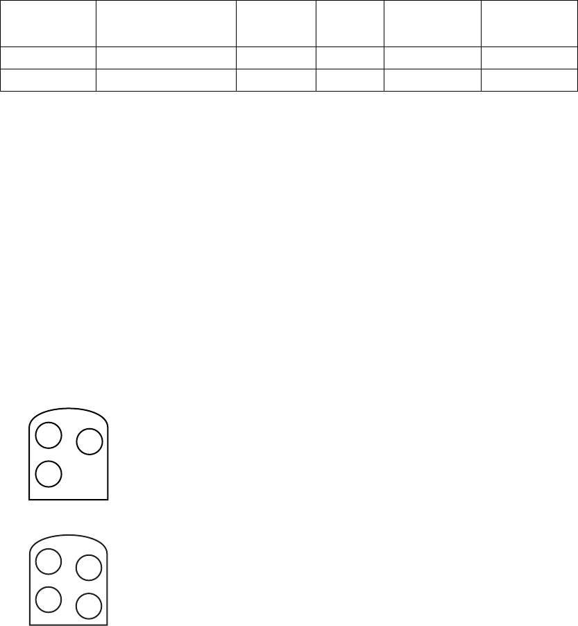
LEAD CONNECTIONS
Lead connections are illustrated below.
CAUTION: Do not use any lead with this device without first verifying
connector compatibility. Using incompatible leads can damage the connector
and/or result in potential adverse consequences, such as undersensing of
cardiac activity or failure to deliver necessary therapy.
– +
RV
DF-1
IS-1
BI
DF-1
Figure 1-1. Lead connections, single chamber
– +
RV RA
DF-1
IS-1
BI
DF-1
IS-1
BI
Figure 1-2. Lead connections, dual chamber
- DRAFT -
INFORMATION FOR USE
ITEMS INCLUDED IN PACKAGE 1-21
NOTE: The pulse generator case is used as a defibrillating electrode unless
the pulse generator has been programmed to the Distal Coil to Proximal Coil
(or “Cold Can”) Shock Vector.
ITEMS INCLUDED IN PACKAGE
The following items are included with the pulse generator:
• One torque wrench
• Product literature
• One patient data disk
NOTE: Accessories (e.g., wrenches) are intended for one-time use only.
They should not be resterilized or reused.
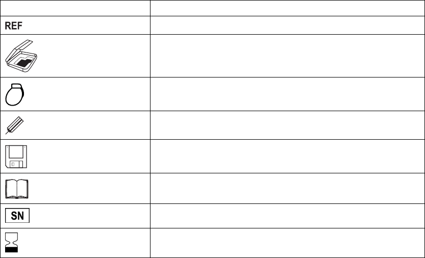
SYMBOLS ON PACKAGING
The following symbols may be used on pulse generator packaging and labeling
(Table 1-2 on page 1-21):
Table 1-2. Symbols on packaging
Symbol Description
Reference number
Package contents
Pulse generator
Torque wrench
Disk for data storage
Literature enclosed
Serial number
Use by
- DRAFT -
1-22 INFORMATION FOR USE
CHARACTERISTICS AS SHIPPED
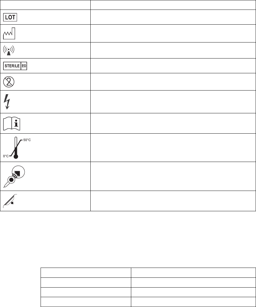
Table 1-2. Symbols on packaging (continued)
Symbol Description
Lot number
Date of manufacture
Non-ionizing electromagnetic radiation
Sterilized using ethylene oxide
Do not reuse
Dangerous voltage
Consult instructions for use
Temperature limitation
Wand placement indicator for interrogation
Opening instruction
CHARACTERISTICS AS SHIPPED
Refer to the table for pulse generator settings at shipment (Table 1-3 on page
1-22).
Table 1-3. Characteristics as shipped
Parameter Setting
Tachy Mode Storage
Tachy Therapy available ATP, Shock
Pacing Mode Storage
- DRAFT -

INFORMATION FOR USE
X-RAY IDENTIFIER 1-23
Table 1-3. Characteristics as shipped (continued)
Parameter Setting
Pacing Therapy available DDDR (DR models) VVIR (VR models)
Sensor Accelerometer (MV for respiratory rate trend)
Pace/Sense Configuration RA: BI/BI (DR models)
Pace/Sense Configuration RV: BI/BI
The pulse generator is shipped in a power-saving Storage mode to extend its
shelf life. In Storage mode, all features are inactive except:
• Telemetry support, which allows interrogation and programming
• Real-time clock
• Commanded capacitor re-formation
• STAT SHOCK and STAT PACE commands
The device leaves Storage mode when one of the following actions occurs;
however, programming other parameters will not affect the Storage mode:
• STAT SHOCK or STAT PACE is commanded
• Tachy Mode is programmed to:
–Off
– Monitor Only
– Monitor + Therapy
Once you have programmed the pulse generator out of Storage mode, the
device cannot be reprogrammed to that mode.
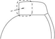
X-RAY IDENTIFIER
The pulse generator has an identifier that is visible on x-ray film or under
fluoroscopy. This identifier provides noninvasive confirmation of the
manufacturer and consists of the following:
• The letters, BOS, to identify Boston Scientificasthemanufacturer
• The number, 112, to identify the Model 2868 PRM software application
needed to communicate with the pulse generator
- DRAFT -
1-24 INFORMATION FOR USE
FEDERAL COMMUNICATIONS COMMISSION (FCC)
The x-ray identifier is embedded in the header of the device at the approximate
location (Figure 1-3 on page 1-24).
Header
Pulse Generator Case
X-Ray Identifier
Figure 1-3. X-ray identifier
For information on identifying the device via the PRM, refer to the PRM
operator’s manual.
The pulse generator model number is stored in device memory and is shown
on the PRM summary screen once the pulse generator is interrogated.
FEDERAL COMMUNICATIONS COMMISSION (FCC)
This device complies with Title 47, Part 15 of the FCC rules. Operation is
subject to the following two conditions:
• This device may not cause harmful interference, and
• This device must accept any interference received, including interference
that may cause undesired operation.
CAUTION: Changes or modifications not expressly approved by Boston
Scientific could void the user’s authority to operate the equipment.
INDUSTRY CANADA (IC)
This device complies with Radio Standards Specification RSS-210. Operation
is subject to the following two conditions:
• This device may not cause harmful interference, and
• This device must accept any interference received, including interference
that may cause undesired operation.
CAUTION: Changes or modifications not expressly approved by Boston
Scientific could void the user’s authority to operate the equipment.
- DRAFT -

INFORMATION FOR USE
PULSE GENERATOR LONGEVITY 1-25
PULSE GENERATOR LONGEVITY
Based on simulated studies, it is anticipated that these pulse generators have
average longevity to explant as shown below.
The longevity expectations, which account for the energy used during
manufacture and storage, apply at the conditions shown in the table along
with the following:
• Assumes 60 ppm LRL, ventricular and atrial settings of 2.5 V pacing pulse
amplitude and 0.4 ms pacing pulse width; RA Impedance 500 .
• Projected longevity is calculated at 6 to 14 maximum energy charging cycles
per year (depending on battery status) with automatic capacitor/battery
management and maximum energy charges, and 3-channel EGM Onset
set to On.
Table 1-4. Pulse generator life expectancy estimation (implant to explant) for HE models
HE Modelsa
Longevity (years) at 500 Ω,700Ω,
and 900 ΩPacing Impedance (RV)
500 Ohms 700 Ohms 900 Ohms
Pacing VR DR VR DR VR DR
0% 8.7 8.3 8.7 8.3 8.7 8.3
15% 8.4 7.8 8.5 7.9 8.6 8.0
50% 8.1 7.3 8.2 7.5 8.3 7.6
100% 7.8 6.7 8.0 6.9 8.1 7.0
a. For RF-enabled models, assumes ZIP telemetry use for 1 hour at implant time and for 20 minutes during
each quarterly follow-up.
NOTE: The energy consumption in the longevity table is based upon
theoretical electrical principles and verified via bench testing only.
The pulse generator longevity may increase with a decrease in any of the
following:
• Pacing rate
• Pacing pulse amplitude(s)
• Pacing pulse width(s)
• Percentage of paced to sensed events
- DRAFT -
1-26 INFORMATION FOR USE
WARRANTY INFORMATION
• Charging frequency
Longevity is also reduced in the following circumstances:
• With a decrease in pacing impedance
• When Patient Triggered Monitor is programmed to On
• For models with ZIP wandless telemetry, one hour of additional telemetry
reduces longevity by approximately 7 days.
Device longevity may also be affected by:
• Tolerances of electronic components
• Variations in programmed parameters
• Variations in usage as a result of patient condition
An additional maximum-energy shock reduces longevity by approximately
19 days.
Refer to the PRM Summary screen for an estimate of pulse generator longevity
specific to the implanted device.
WARRANTY INFORMATION
A limited warranty certificate for the pulse generator is packaged with the
device. For additional copies, please contact Boston Scientific at the address
and phone number shown on the back cover of this manual.
PRODUCT RELIABILITY
It is Boston Scientific’s intent to provide implantable devices of high quality and
reliability. However, these devices may exhibit malfunctions that may result in
lost or compromised ability to deliver therapy. These malfunctions may include
the following:
• Premature battery depletion
• Sensing or pacing issues
• Inability to shock
• Error codes
• Loss of telemetry
- DRAFT -
INFORMATION FOR USE
PATIENT COUNSELING INFORMATION 1-27
Refer to Boston Scientific’s CRM Product Performance Report on
www.bostonscientific.com for more information about device performance,
including the types and rates of malfunctions that these devices have
experienced historically. While historical data may not be predictive of future
device performance, such data can provide important context for understanding
the overall reliability of these types of products.
Sometimes device malfunctions result in the issuance of safety advisories.
Boston Scientific determines the need to issue safety advisories based on
theestimatedmalfunctionrateandtheclinical implication of the malfunction.
When Boston Scientific communicates safety advisory information, the
decision whether to replace a device should take into account the risks of the
malfunction, the risks of the replacement procedure, and the performance to
date of the replacement device.
PATIENT COUNSELING INFORMATION
The following topics should be discussed with the patient prior to discharge.
• The patient should:
– Contact their physician immediately if they hear tones coming from
their pulse generator
– Contact their physician to have their pulse generator system evaluated
if they receive external defibrillation
– Understand the signs and symptoms of infection
– Understand the symptoms that should be reported (e.g., sustained
high-rate pacing requiring reprogramming)
– Seek medical guidance before entering protected environments such
as areas protected by a warning notice that prevents entry by patients
whohaveapulsegenerator
– Understand and avoid potential sources of EMI and magnetic fields
in home, work, and medical environments (See Warnings and
Precautions for more detailed information about specific sources)
• Persons administering CPR may experience the presence of voltage
(tingling) on the patient’s body surface when the pulse generator delivers
ashock.
- DRAFT -
1-28 INFORMATION FOR USE
PATIENT COUNSELING INFORMATION
• It is Boston Scientific’s intent to provide implantable devices of high quality
and reliability. However, these devices may exhibit malfunctions that may
result in lost or compromised ability to deliver therapy. When Boston
Scientific communicates safety advisory information, the decision whether
to replace a device should take into account the risks of the malfunction,
the risks of the replacement procedure, and the performance to date of the
replacement device.
Patient Handbook
The Patient Handbook is provided for each device.
It is recommended that you discuss the information in the Patient Handbook
with concerned individuals both before and after implantation so they are fully
familiar with pulse generator operation.
For additional copies, contact your sales representative, or contact Boston
Scientific at the phone number shown on the back cover of this manual.
- DRAFT -

2-1
USING THE PROGRAMMER/RECORDER/MONITOR
CHAPTER 2
This chapter contains the following topics:
• "ZOOM LATITUDE Programming System" on page 2-2
• "Indications-Based Programming (IBP)" on page 2-2
• "Manual Programming" on page 2-5
• "Software Terminology and Navigation" on page 2-6
• "Data Management" on page 2-11
• "Communicating with the Pulse Generator" on page 2-12
• "DIVERT THERAPY" on page 2-17
• "STAT SHOCK" on page 2-17
• "STAT PACE" on page 2-18
• "Safety Mode" on page 2-19
- DRAFT -
2-2 USING THE PROGRAMMER/RECORDER/MONITOR
ZOOM LATITUDE PROGRAMMING SYSTEM
ZOOM LATITUDE PROGRAMMING SYSTEM
The ZOOM LATITUDE Programming System is the external portion of the
pulse generator system and includes:
• Model 3120 Programmer/Recorder/Monitor (PRM)
• Model 2868 ZOOMVIEW Software Application
• Model 6577 Accessory Telemetry Wand
The ZOOMVIEW software provides advanced device programming and patient
monitoring technology. It was designed with the intent to:
• Enhance device programming capability
• Improve patient and device monitoring performance
• Simplify and expedite programming and monitoring tasks
YoucanusethePRMsystemtodothefollowing:
• Interrogate the pulse generator
• Program the pulse generator to provide a variety of therapy options
• Access the pulse generator’s diagnostic features
• Perform noninvasive diagnostic testing
• Access therapy history data
You can program the pulse generator using two methods: automatically using
IBP or manually.
INDICATIONS-BASED PROGRAMMING (IBP)
IBP is a tool that provides specific programming recommendations based on
the patient’s clinical needs and primary indications.
IBP is a clinical approach to programming that was developed based on
physician consultation and case studies. The intent of IBP is to enhance patient
outcomes and save time by providing base programming recommendations
that you can customize as needed. IBP systematically presents the specific
features intended for use with the clinical conditions you identify in the IBP user
interface, and allows you to take maximum advantage of the pulse generator’s
capabilities.
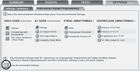
IBP can be accessed from the Settings tab on the main application screen
(Figure 2-1 on page 2-3).
- DRAFT -
USING THE PROGRAMMER/RECORDER/MONITOR
INDICATIONS-BASED PROGRAMMING (IBP) 2-3
Figure 2-1. Indications-based Programming screen
Indications are clustered in general categories as illustrated above. The intent
for each category of indications is described below:
• Sinus Node:
– If Normal is selected, the intent is to provide RV pacing when necessary.
– If Chronotropically Incompetent is selected, the intent is to provide
rate-adaptive pacing.
– If Sick Sinus Syndrome is selected, the intent is to provide atrial pacing
support.
• AV Node:
– If Normal or 1st Degree Block is selected, the intent is to provide RV
pacing when necessary.
– If 2nd Degree Block is selected, the intent is to promote intrinsic AV
conduction and provide AV sequential pacing when conduction is not
present.
– If Complete Heart Block is selected, the intent is to provide AV
sequential pacing.
NOTE: The selected settings for AF and Sinus Node may affect the suggested
value for the Normal/1st Degree Block setting of AV Node.
- DRAFT -
2-4 USING THE PROGRAMMER/RECORDER/MONITOR
INDICATIONS-BASED PROGRAMMING (IBP)
• Atrial Arrhythmias
– If Paroxysmal/Persistent is selected, the intent is to avoid tracking
atrial arrhythmias by using dual-chamber pacing mode with ATR Mode
Switch.
– If Permanent/Chronic AF is selected, the intent is to provide rate
adaptive RV pacing.
• Ventricular Arrhythmias
– When History of VF/SCD or Prophylaxis for VT/VF is selected, a
2-zone configuration with the following rate thresholds and therapies
is provided:
– 180 bpm for the VF zone with QUICK CONVERT ATP and
Maximum Energy Shocks enabled
– 160 bpm for the VT zone with therapy disabled (Monitor Only)
– When History of VT/VF is selected, a 2-zone configuration with the
following rate thresholds and therapies is provided:
– 200 bpm for the VF zone with QUICK CONVERT ATP and
Maximum Energy Shocks enabled
– 160 bpm for the VT zone with ATP and Maximum Energy Shocks
enabled
– Rhythm ID enabled
– When VF Only is selected, the intent is for a single VF zone of 220 bpm
is provided with only Maximum Energy Shocks enabled.
When you have chosen the patient indications, select the View Recommended
Settings button to view a summary of the programming recommendations
(Figure 2-2 on page 2-5).
- DRAFT -
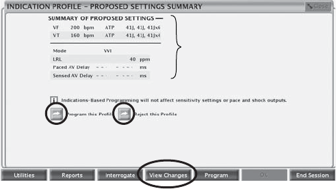
USING THE PROGRAMMER/RECORDER/MONITOR
MANUAL PROGRAMMING 2-5
NOTE: You must view the settings before you can program them. Selecting
the View Recommended Settings button allows you to view the settings
that are recommended based on the indications that you selected. Viewing
the recommended settings does not overwrite any pending (i.e., not yet
programmed) parameter changes. You must choose to program or reject
the recommended settings after viewing them. If you choose to reject the
recommended settings, all of your pending settings will be restored. If you
choose to program the recommended settings, any pending parameter
changes will be overwritten, with the exception of sensitivity, shock outputs,
and pacing outputs, which are independent of IBP.
Primary
Settings
Summary
Figure 2-2. Proposed Settings Summary screen
The Proposed Settings Summary screen displays the primary programming
recommendations. Additional details about all changed parameters are
available by selecting the View Changes button from the toolbar. You have the
option to program the proposed settings or reject them, as long as telemetry
is still engaged:
• Program—select the Program this Profile button to accept the proposed
settings.
• Reject—select the Reject this Profile button to reject the proposed settings;
this action will return you to the main IBP screen with no changes made.
MANUAL PROGRAMMING
Manual programming controls such as sliders and menus are available to allow
you to individually adjust pulse generator program settings.
Manual programming controls are located on the Settings Summary tab, which
can be accessed from the Settings tab or by selecting the Settings Summary
button on the Summary tab. Refer to other feature descriptions in this manual
- DRAFT -
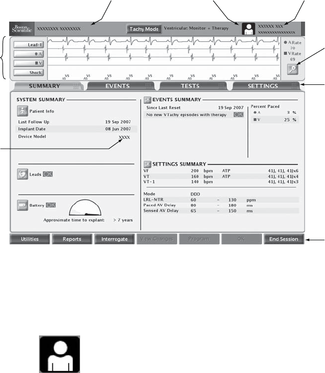
2-6 USING THE PROGRAMMER/RECORDER/MONITOR
SOFTWARE TERMINOLOGY AND NAVIGATION
for specific manual programming information and instructions. Refer to
"Programmable Options" on page A-1 for detailed listings of available settings.
SOFTWARE TERMINOLOGY AND NAVIGATION
This section provides an overview of the PRM system.
Main Screen
The main PRM screen is shown below, followed by a description of the
components (Figure 2-3 on page 2-6).
Patient name Device name
Details
button
Tab s
ECG/EGM
display
Toolbar
Device
model
PRM Mode Indicator
Figure 2-3. Main Screen
PRM Mode Indicator
The PRM Mode Indicator displays at the top of the screen to identify the current
PRM operational mode.
Patient—indicates that the PRM is displaying data obtained by
communicating with a device.
- DRAFT -

USING THE PROGRAMMER/RECORDER/MONITOR
SOFTWARE TERMINOLOGY AND NAVIGATION 2-7
Patient Data Disk—indicates that the PRM is displaying stored
data from a patient data disk.
Demo Mode—indicates that the PRM is displaying sample data
and operating in demonstration mode.
ECG/EGM Display
The ECG area of the screen shows real-time status information about the
patient and the pulse generator. This information is useful in evaluating system
performance:
• Real-time EGMs can be transmitted from the pace/sense or shocking
electrodes to evaluate lead system integrity and help identify faults such as
lead fractures, insulation breaks, or dislodgments.
• Annotated event markers identify certain intrinsic cardiac and device-related
events, and provide information such as sensed/paced events, decision of
detection criteria, and therapy delivery.
You can select the Details button to enlarge the ECG/EGM screen. The
following options are available:
• Show Device Markers—displays annotated markers
• Enable Surface Filter—minimizes noise on the surface ECG
• Display Pacing Spikes—shows detected pacing spikes, annotated by a
marker on the surface ECG waveform
You can print a real-time EGM report, which includes annotated event markers,
by performing the following steps:
1. Press one of the print speed keys on the PRM (for example, speed key 25).
2. Press the Paper Form Feed key. The EGM report will begin printing.
You can print a report containing the definitions of all of the annotated markers
by performing the following steps:
1. From the toolbar, click the Reports button. The Reports window displays.
2. Select the Marker Legend checkbox.
3. Click the Print button. The Marker Legend Report is sent to the printer.
- DRAFT -

2-8 USING THE PROGRAMMER/RECORDER/MONITOR
SOFTWARE TERMINOLOGY AND NAVIGATION
Toolbar
Thetoolbarallowsyoutoperformthefollowingtasks:
• Select system utilities
• Generate reports
• Interrogate and program the pulse generator
• View pending or programmed changes
• View attentions and warnings
• End your PRM session
Tabs
Tabs allow you to select PRM tasks, such as viewing summary data or
programming device settings. Selecting a tab displays the associated screen.
Many screens contain additional tabs, which allow you to access more detailed
settings and information.
Buttons
Buttons are located on screens and dialogs throughout the application. Buttons
allow you to perform various tasks, including:
• Obtain detailed information
• View setting details
• Set programmable values
When a button selection opens a window in front of the Main Screen, a Close
button displays in the upper-right corner of the window to allow you to close the
window and return to the Main Screen.
Icons
Icons are graphic elements that, when selected, may initiate an activity, display
lists or options, or change the information displayed.
Details—opens a window containing detailed information.
- DRAFT -

USING THE PROGRAMMER/RECORDER/MONITOR
SOFTWARE TERMINOLOGY AND NAVIGATION 2-9
Patient—opens a window with patient information details.
Leads—opens a window with details on leads.
Battery—opens a window with details on the pulse generator
battery.
Run—causes the programmer to perform an action.
Check—indicates that an option is selected.
Event—indicates that an event has occurred. When you view the
Trends timeline on the Events tab, event icons display wherever
events have occurred. Selecting an events icon displays details
about the event.
Slider Icons
Horizontal Slider—indicates that a slider object can be clicked
and dragged left or right.
Vertical Slider—indicates that a slider object can be clicked and
dragged up or down.
Sort Icons
Sort Ascending—indicates that Ascending sort is currently
selected on a table column sort button. (e.g., 1, 2, 3, 4, 5)
Sort Descending—indicates that Descending sort is currently
selected on a table column sort button. (e.g., 5, 4, 3, 2, 1)
- DRAFT -

2-10 USING THE PROGRAMMER/RECORDER/MONITOR
SOFTWARE TERMINOLOGY AND NAVIGATION
Increment and Decrement Icons
Increment—indicates that an associated value can be
incremented.
Decrement—indicates that an associated value can be
decremented.
Scroll Icons
Scroll Left—indicates that an associated item can be scrolled left.
Scroll Right—indicates that an associated item can be scrolled
right.
Scroll Up—indicates that an associated item can be scrolled up.
Scroll Down—indicates that an associated item can be scrolled
down.
Common Objects
Common objects such as status bars, scroll bars, menus, and dialogs are used
throughout the application. These operate similarly to the objects found in web
browsers and other computer applications.
Use of Color
Colors are used to highlight buttons, icons, and other objects. The use of
specific color conventions is intended to provide a more consistent user
experience and simplify programming.
Red and yellow are used to provide Warning and Attention indications, as
described below:
• Red—indicates Warning conditions such as the following:
– The selected device parameter value is not allowed
– Device and patient diagnostic information that requires serious
consideration
- DRAFT -
USING THE PROGRAMMER/RECORDER/MONITOR
DATA MANAGEMENT 2-11
• Yellow—indicates Attention conditions such as the following:
– The selected device parameter value is not recommended, but is
allowed
– Device and patient diagnostic information that should be addressed
When a red Warning or yellow Attention button displays in the toolbar, click the
button. The Parameter Interactions screen will display, with information about
corrective action.
DATA MANAGEMENT
The PRM system allows you to manage patient and pulse generator data by
viewing, printing, storing, or retrieving it. This section describes the PRM data
management capabilities.
Patient Information
Information about the patient can be stored in pulse generator memory. The
information is accessible from the Summary screen by selecting the Patient
icon. This information includes, but is not limited to, the following:
• Patient and physician names
• Pulse generator serial number
• Implant date
• Lead configurations
• Implant test measurements
The information can be retrieved at any time by interrogating the pulse
generator and viewing it on the PRM screen or printing it as a report.
Disk Operations
The PRM system allows you to store patient data on a removable data disk.
Toaccessthedatastoredonadisk,first select the Utilities button, then select
the Disk tab. Insert a disk into the disk drive, and select one of the following
disk options:
• Read Disk—allows you to retrieve saved data from a patient data disk
- DRAFT -
2-12 USING THE PROGRAMMER/RECORDER/MONITOR
COMMUNICATING WITH THE PULSE GENERATOR
• Save All to Disk—allows you to save information to a disk, including the
following:
– Therapy history
– Programmed parameter values
– Trending values
– Histogram paced/sensed counters
Print
You can print PRM reports by using the internal printer, or by connecting to an
external printer. To print a report, select the Reports button. Then select the
report you wish to print from the following categories:
• Follow-up reports
• Episode reports
• Other reports (includes device settings, patient data, and other information)
COMMUNICATING WITH THE PULSE GENERATOR
The PRM communicates with the pulse generator using a telemetry wand.
After initiating communication with the wand, some pulse generator models can
use wandless ZIP telemetry (two-way RF communication) to interface with the
PRM. Wanded or ZIP telemetry is required to:
• Direct commands from the PRM system, such as:
– INTERROGATE
–PROGRAM
– STAT SHOCK
–STATPACE
– DIVERT THERAPY
• Modify device parameter settings
• Conduct EP testing
- DRAFT -
USING THE PROGRAMMER/RECORDER/MONITOR
COMMUNICATING WITH THE PULSE GENERATOR 2-13
• Conduct diagnostic tests including the following:
– Pacing impedance tests
– Pacing threshold tests
– Intrinsic amplitude tests
• Perform manual capacitor re-form
ZIP Telemetry
ZIP telemetry is a wandless, two-way RF communication option that allows the
PRM system to communicate with some pulse generator models. When a
wanded telemetry session is initiated, the PRM checks the pulse generator’s
telemetry capability. If the PRM detects a pulse generator with ZIP telemetry
capability, a message will display indicating that ZIP telemetry is available and
the wand can be removed. Otherwise, the session will continue with wanded
telemetry.
ZIP telemetry offers the following advantages over traditional wanded telemetry:
• The faster data transmission speed means less time is required for device
interrogation
• Data transmission over a longer distance (within 3 meters) minimizes the
need to keep the wand in the sterile field during implant, which may reduce
the risk of infection
• Continuous telemetry is possible during the entire implant procedure,
allowing monitoring of pulse generator performance and lead integrity
during implant
Regardless of whether ZIP telemetry is being used, wanded communication
is still available.
Starting a Wanded Telemetry Session
Follow this procedure to begin a wanded telemetry communication session:
1. Make sure the telemetry wand is connected to the PRM system and is
available throughout the session.
2. Position the wand over the pulse generator at a distance not greater than 6
cm (2.4 inches).
- DRAFT -
2-14 USING THE PROGRAMMER/RECORDER/MONITOR
COMMUNICATING WITH THE PULSE GENERATOR
3. Use the PRM to Interrogate the pulse generator.
4. Retain the wand position whenever communication is required.
Starting a ZIP Telemetry Session
Follow this procedure to begin a ZIP telemetry communication session:
1. Start a wanded telemetry session. Verify that the wand cord is within reach
of the pulse generator to enable the use of wanded telemetry should it
become necessary.
2. Keep the telemetry wand in position until either a message appears,
indicating that the telemetry wand may be removed from proximity of the
pulse generator, or the ZIP telemetry light illuminates on the PRM system.
Ending a Telemetry Session
Select the End Session button to quit a telemetry session and return to the
startup screen. You can choose to end the session or return to the current
session. Upon ending a session, the PRM system terminates all communication
with the pulse generator.
ZIP Telemetry Security
The pulse generator is a compliant low-power transceiver. The pulse generator
can only be interrogated or programmed by RF signals that employ the
proprietary ZIP telemetry protocol. The pulse generator verifies that it is
communicating with a ZOOMVIEW system before responding to any RF
signals. The pulse generator stores, transmits, and receives individually
identifiable health information in an encrypted format.
ZIP telemetry is possible when all of the following conditions are met:
• ZIP telemetry setting for the PRM is programmed On
• The pulse generator has RF communication capabilities
• The ZIP telemetry channel is available for use
• The pulse generator is within range of the PRM system
• The pulse generator has not reached Explant; note that a total of 1.5 hours
of ZIP telemetry will be available after the pulse generator reaches Explant
• The pulse generator battery capacity is not depleted
- DRAFT -
USING THE PROGRAMMER/RECORDER/MONITOR
COMMUNICATING WITH THE PULSE GENERATOR 2-15
In order to meet local communications rules and regulations, ZIP telemetry
should not be used when the pulse generator is outside its normal operating
temperature of 20°C–43°C (68°F–109°F).
The PRM supports communication between two PRMs and two pulse
generators at a time, as two independent sessions. If there are two PRMs
already communicating in the vicinity, a third session will not be allowed to start;
wanded communication will be necessary in this case.
The PRM notifies you if ZIP telemetry is unavailable because of other sessions
already in progress.
RF signals in the same frequency band used by the system may interfere with
ZIP telemetry communication. These interfering signals include:
• Signals from other pulse generator/PRM system RF communication
sessions after the maximum number of independent sessions has been
reached. Other nearby pulse generators and PRMs using ZIP telemetry
may prevent ZIP telemetry communication.
• Interference from other RF sources.
CAUTION: RF signals from devices that operate at frequencies near that
of the pulse generator may interrupt ZIP telemetry while interrogating or
programming the pulse generator. This RF interference can be reduced by
increasing the distance between the interfering device and the PRM and pulse
generator. Examples of devices that may cause interference include:
• Cordless phone handsets or base stations
• Certain patient monitoring systems
• Remote control toys
Radio frequency interference may temporarily disrupt ZIP telemetry
communication. The PRM will normally reestablish ZIP communication when
the RF interference ends or subsides. Because continued RF interference may
prevent ZIP telemetry communication, the system is designed to use wanded
telemetry when ZIP telemetry is not available.
If ZIP telemetry is not available, wanded telemetry communication with the
PRM can be established. The system provides the following feedback to
indicate that ZIP telemetry is not available:
• The ZIP telemetry indicator light on the PRM turns off
- DRAFT -
2-16 USING THE PROGRAMMER/RECORDER/MONITOR
COMMUNICATING WITH THE PULSE GENERATOR
• If event markers and/or EGMs are activated, transmission of the event
markers and/or EGMs is interrupted
• If a command or other action has been requested, the PRM displays a
notification indicating the wand should be placed in range of the pulse
generator
ZIP telemetry operates consistently with wanded telemetry—no programming
step can be completed unless the entire programming command has been
received and confirmed by the pulse generator.
The pulse generator cannot be misprogrammed as a result of interrupted ZIP
telemetry. Interruptions of ZIP telemetry may be caused by RF signals that
operate at frequencies near that of the pulse generator and are strong enough
to compete with the ZIP telemetry link between the pulse generator and the
PRM. Significant interference may result in a break or drop-outs of real-time
EGMs. If commands are interrupted, the PRM displays a message to place
the wand on the pulse generator. These situations can be resolved by using
standard wanded telemetry. There will be no interruption of device functionality
or therapy during this period.
NOTE: The PRM operates on a specific frequency range depending on
geography. The PRM determines the ZIP frequency range that the pulse
generator uses based on the specific device model. If the PRM and pulse
generator ZIP frequency ranges do not match, it indicates that the patient has
traveled outside their geography. The PRM will display a message indicating
that ZIP telemetry cannot be used; however, the patient’s pulse generator can
be interrogated by using the wand.
Considerations for Reducing Interference
Increasing the distance from the source of interfering signals may enable the
use of the ZIP telemetry channel.
Repositioning the PRM antenna or repositioning the PRM may improve ZIP
telemetry performance. If ZIP telemetry performance is not satisfactory, the
option of using wanded telemetry is available.
Depending on the environment and PRM orientation relative to the pulse
generator, the system is capable of maintaining ZIP telemetry communication
at distances up to 12 m (40 ft). For optimum ZIP telemetry communication,
position the PRM antenna within 3 m (10 ft) of the pulse generator and remove
any obstruction between the PRM and the pulse generator.
- DRAFT -
USING THE PROGRAMMER/RECORDER/MONITOR
DIVERT THERAPY 2-17
DIVERT THERAPY
When the pulse generator is charging to deliver a shock, the shock delivery
may be diverted from the patient. If diverted, the shock does not count as
one of the total number of shocks that may be delivered during an episode. If
redetection occurs and more shock therapy is required, and if more shocks are
available in the therapy prescription, the pulse generator will charge again to
deliver subsequent shocks.
Also, the DIVERT THERAPY key can be pressed to divert ATP therapy in
midburst. If redetection occurs, the ATP scheme will not be used again and the
next programmed therapy in the sequence will be initiated.
1. If you are not already in a session, position the telemetry wand within range
of the pulse generator.
2. Press the DIVERT THERAPY key. A message window will appear
indicating that a divert attempt is being made.
3. If using wanded telemetry, maintain the wand position until the message
window disappears, indicating the shock has been diverted. Prematurely
removing the wand (breaking the telemetry link) may allow the pulse
generator to continue charging and to deliver the shock.
NOTE: There is a 500 ms delay between the end of charging and shock
delivery designed to provide a minimum period for the DIVERT THERAPY
command. After this time, pressing DIVERT THERAPY may not divert the
shock.
STAT SHOCK
A nonprogrammable, maximum-output STAT SHOCK can be delivered to the
patient at any time during a communication session. The STAT SHOCK can be
delivered when the pulse generator’s Tachy Mode is programmed to any mode.
This function does not affect the programmed shock sequences (lower-energy
shocks can be delivered following a STAT SHOCK) and does not count as
one of the total number of shocks in a therapy sequence for a given episode.
The output of the STAT SHOCK is at the maximum-output energy and at
the programmed polarity and waveform; STAT SHOCK is always committed
regardless of programmed parameters.
1. If you are not already in a session, position the telemetry wand within range
of the pulse generator.
- DRAFT -
2-18 USING THE PROGRAMMER/RECORDER/MONITOR
STAT PACE
2. Press the STAT SHOCK key. A message window appears with information
about the shock and instructions to initiate the shock.
3. To initiate the shock, press the STAT SHOCK key again. A different
message window appears indicating that STAT SHOCK is in process.
When the shock has been delivered, the message window disappears.
4. Subsequent high-energy STAT SHOCKS may be delivered by repeating
the previous steps.
NOTE: TheSTATSHOCKmaybedivertedusingtheDIVERTTHERAPYkey.
NOTE: Following STAT SHOCK delivery, if the Tachy Mode is programmed
to Monitor Only or Monitor + Therapy, post-shock redetection is initiated
(initial detection criteria and enhancements are not used). If the Tachy Mode
is programmed to Monitor + Therapy and redetection determines that further
therapy is required, the programmed sequence of therapy will be resumed or
initiated, including ATP and/or low-energy shocks.
STAT PACE
Emergency bradycardia pacing using the STAT PACE command sets the
bradycardia operation to parameters intended to ensure capture and keep
the patient stable.
1. If you are not already in a session, position the telemetry wand within range
of the pulse generator.
2. Press the STAT PACE key. A message window displays the STAT PACE
values.
3. Press the STAT PACE key a second time. A message indicates that STAT
PACE is being performed, followed by the STAT PACE values.
4. Select the Close button on the message window.
5. To stop STAT PACE, reprogram the pulse generator.
CAUTION: When a pulse generator is programmed to STAT PACE settings,
it will continue to pace at the high-energy STAT PACE values if it is not
reprogrammed. The use of STAT PACE parameters will decrease device
longevity.
- DRAFT -
USING THE PROGRAMMER/RECORDER/MONITOR
SAFETY MODE 2-19
SAFETY MODE
The pulse generator hardware includes a safety core feature. The safety core
is intended to provide life-sustaining therapy in the event of specific failures
within the pulse generator. If the pulse generator is interrogated while safety
core is active, the PRM will indicate that the pulse generator is in Safety Mode.
Limited inductive telemetry and some device programming are available during
Safety Mode. If you interrogate a pulse generator that is in Safety Mode, the
PRM will display a warning screen directing you to call Technical Services.
Backup Pacemaker
The Safety Mode feature provides a simple VVI pacemaker programmed to
72.5 ppm, with the following output characteristics.
• 5 V amplitude
• 1.0 ms pulse width
Backup Defibrillator
The Safety Mode feature provides a single-zone backup defibrillator, which can
be enabled or disabled using the PRM.
Tachycardia Detection in Safety Mode
In Safety Mode, the tachycardia detection monitors RV senses using a
traditional tachycardia detection window with a rate threshold of 165 bpm.
Tachycardia Therapy in Safety Mode
In Safety Mode, tachycardia therapy consists of maximum energy, committed
shocks, with the following settings:
• Shock polarity—initial
• Shock waveform—biphasic
• Shock vector—V-TRIAD
Within the period of a declared episode, therapy is limited to 5 shocks.
When a magnet is detected, therapy delivery is immediately inhibited although
charging may continue. After the magnet has been applied for 1 second,
- DRAFT -
2-20 USING THE PROGRAMMER/RECORDER/MONITOR
SAFETY MODE
the therapy is diverted and detection is inhibited. The magnet must then be
removed for 2 seconds in order to allow detection to continue.
Programming the Device Safety Tachy Mode
In Safety Mode, you can perform the following steps to program the Safety
Tachy Mode:
1. Select the Tachy Mode button. The Change Device Mode dialog displays.
2. Click to select the required Safety Tachy Mode setting, either Off or Monitor
+ Therapy. Click Apply Changes to apply the new setting, or Cancel
Changes to cancel the new setting.
3. Click Close to dismiss the Change Device Mode dialog.
NOTE: The safety tachy mode automatically will be set to Off if additional
faults are detected while in Safety Mode.
- DRAFT -

3-1
TACHYARRHYTHMIA DETECTION
CHAPTER 3
This chapter contains the following topics:
• "Device Mode" on page 3-2
• "Rate Sensing" on page 3-3
• "Ventricular Detection" on page 3-6
- DRAFT -

3-2 TACHYARRHYTHMIA DETECTION
DEVICE MODE
DEVICE MODE
TheDeviceModeallowsyoutoprogramthedevicetoprovidethetypeof
therapy and detection desired.
Ventricular Tachy Mode
The Ventricular Tachy Mode controls the availability of the detection and
therapy functions in the ventricle (Table 3-1 on page 3-2).
You can program the Ventricular Tachy Mode to the following modes:
• Off––disables ventricular tachyarrhythmia detection and automatic
ventricular therapy delivery. This mode is useful during implant or explant,
when connecting the leads to or disconnecting them from the pulse
generator.
• Monitor Only––enables ventricular tachyarrhythmia detection and episode
storage, but does not automatically deliver therapy to the patient. This
mode is useful in controlled environments, such as during EP testing,
exercise testing, and immediately postoperative, where alternate therapy
(e.g., external defibrillation) is available.
• Monitor + Therapy––enables the full range of ventricular detection and
ventricular therapy options.
Table 3-1. Device feature availability in the Ventricular Tachy Mode settings
Device features Ventricular Tachy Mode
Off Monitor Only Monitor +
Therapy
Rate sensing XaXX
Bradycardia pacing X X X
Ventricular detection/therapy history XbXX
STAT SHOCK XXX
STAT PACE XXX
Real-time annotated EGMs XXX
Ventricular tachyarrhythmia detection X X
Commanded ventricular ATP XX
c
Commanded ventricular shock XX
- DRAFT -
TACHYARRHYTHMIA DETECTION
RATE SENSING 3-3
Table 3-1. Device feature availability in the Ventricular Tachy Mode settings (continued)
Device features Ventricular Tachy Mode
Off Monitor Only Monitor +
Therapy
Ventricular EP test XdXd
Automatic ventricular tachyarrhythmia therapy X
a. In order to enable ventricular sensing when the Ventricular Tachy Mode is programmed to Off, you must program the Brady Mode
to a mode with ventricular sensing.
b. While programmed to Off Mode, the pulse generator will store only STAT SHOCK in history.
c. When the ventricular tachy mode is Monitor + Therapy, the EP Temp V Mode must be programmed to Monitor Only in order to
use the commanded ventricular ATP.
d. Not all forms of EP Tests are available in this mode.
Electrocautery Protection Mode
Electrocautery Protection Mode deactivates the tachyarrhythmia detection and
therapy features of the pulse generator during use of electrocautery equipment.
When Electrocautery Protection is enabled, bradycardia pacing is still
functional; however, the pacing mode switches to an XOO mode (where X
is determined by the programmed pacing mode). Other pacing parameters
remain at the programmed settings.
After cancelling Electrocautery Protection, the following modes will revert to
the previously programmed settings:
• Ventricular Tachy Mode
• Brady Mode
Except for STAT SHOCK and STAT PACE, no commanded therapies,
inductions, or diagnostic tests will be allowed while Electrocautery Protection is
enabled.
RATE SENSING
Rate sensing is critical to all detection decisions. The pulse generator relies
on the following to determine cardiac cycle length:
• Bipolar electrodes in the atrium and right ventricle.
• Automatic gain-controlled sensing circuit for rate sensing. This circuit
ensures proper rate sensing by compensating for changing or diminished
signal amplitudes.
- DRAFT -

3-4 TACHYARRHYTHMIA DETECTION
RATE SENSING
Calculating Rates and Refractory Periods
The pulse generator evaluates rate on an interval-by-interval basis. Following
a sensed depolarization, a cycle length is measured and compared to the
programmed detection parameters.
The pulse generator uses refractory periods following paced and sensed
intrinsic events; intrinsic events that fall within these periods are ignored for
detection purposes. The refractory periods, together with noise windows, may
prevent the sensing of nonphysiologic signals and the potential delivery of
unwanted therapy. The nonprogrammable refractory periods are as follows:
• 85 ms atrial refractory following an atrial sensed event
• 150 ms atrial refractory following an atrial pace in DDD(R) and DDI(R)
modes
• 135 ms RV refractory following an RV sensed event or a capacitor charge
• 500 ms refractory following shock delivery (sensing is ignored in all
chambers)
Ventricular Rate Thresholds and Zones
The pulse generator compares each sensed RV cardiac cycle interval against
the programmed Ventricular Tachyarrhythmia Rate Threshold.
A Ventricular Tachyarrhythmia Zone is a range of heart rates defined by at
least one programmed Ventricular Tachyarrhythmia Rate Threshold. You can
program from 1 to 3 Ventricular Tachyarrhythmia Zones, each of which can be
treated by a separate therapy prescription (Table 3-2 on page 3-4, Figure 3-1
on page 3-5).
Table 3-2. Nominal values for Ventricular Rate Threshold configurations
Ventricular Zone Configuration VT-1 Zone VT Zone VF Zone
1 Zone –– –– 200 bpm
- DRAFT -
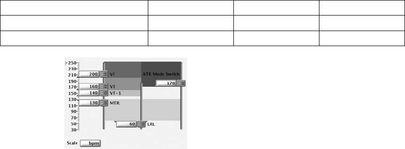
TACHYARRHYTHMIA DETECTION
RATE SENSING 3-5
Table 3-2. Nominal values for Ventricular Rate Threshold configurations (continued)
Ventricular Zone Configuration VT-1 Zone VT Zone VF Zone
2 Zones –– 160 bpm 200 bpm
3 Zones 140 bpm 160 bpm 200 bpm
Figure 3-1. Ventricular Tachy Detection settings
• Rate thresholds in adjacent zones must differ by at least 20 bpm
• The lowest Ventricular Tachyarrhythmia Rate Threshold must be at least
5 bpm higher than the MTR, MSR, and the MPR
• The lowest Ventricular Tachyarrhythmia Rate Threshold must be at least
15 bpm higher than the LRL
Use of Atrial Information
The atrial rate may be used to:
• Inhibit ventricular therapy in the presence of atrial fibrillation or atrial flutter
• Bypass ventricular therapy inhibitors if the ventricular rate is faster than
the atrial rate
The pulse generator will respond to atrial sensing regardless of whether an
atrial lead is implanted. If an atrial lead is not implanted or it has a fault,
program the atrial lead from Bipolar to Off (when programmed to Off, atrial
sensing is not performed; atrial pacing will occur). When programming the
atrial lead to Off, change the Brady Mode to prevent atrial sensing or pacing.
Next, on the applicable VT/VT-1 Detection Enhancement screens, program the
following features accordingly to avoid the use of erroneous atrial data:
• V Rate > A Rate––program to Off (for Onset/Stability detection
enhancement suite)
- DRAFT -
3-6 TACHYARRHYTHMIA DETECTION
VENTRICULAR DETECTION
• AFib Rate Threshold––program to Off (for Onset/Stability detection
enhancement suite)
• Atrial Tachyarrhythmia Discrimination––program to Off (for Rhythm ID
detection enhancement suite)
• Brady Mode––program to Off, VVI, or VVI(R)
• Atrial Rate EGM––do not select the atrial trace
NOTE: An atrial EP test should not be performed if the atrial lead is
programmed to Off.
VENTRICULAR DETECTION
Ventricular detection consists of the following components:
• Initial ventricular detection
• Reconfirmation/committed shock
• Redetection and post-shock detection
Initial ventricular detection criteria consist of the programmable parameters
Rate and Duration. The detection criteria may also include one of the following
two detection enhancement suites, which may be used during initial and
post-shock ventricular detection to add specificity beyond Rate and Duration.
• Onset/Stability
•RhythmID
The pulse generator initiates ventricular therapy when it determines that
detection is met. Ventricular detection is met when all of the following occur:
• A ventricular zone’s detection window becomes and remains satisfied
throughout Duration
• The ventricular zone’s Duration expires
• A higher ventricular zone’s detection window is not satisfied
• Detection enhancements (if programmed to On) indicate therapy
• The last detected interval is in the ventricular zone
If the above criteria are not met, therapy is not initiated and the pulse generator
continues to evaluate intervals.
- DRAFT -

TACHYARRHYTHMIA DETECTION
VENTRICULAR DETECTION 3-7
Ventricular Detection Enhancement Suites
One of the following ventricular detection enhancement suites may be
programmed to provide specificity beyond Rate and Duration (Table 3-3 on
page 3-7):
•RhythmID
• Onset/Stability
Detection enhancement suites are not available in the VF zone.
Table 3-3. Detection enhancement suites available per zone
VT-1 Zone VT Zone VF Zone
Rhythm ID Rhythm ID
3-zone configurationa
Onset/Stability Onset/Stabilityc
None
Rhythm ID
3-zone configuration (with Monitor Only
zone)b
None
Onset/Stability
None
Rhythm ID
2-zone configuration
Onset/Stability
None
2-zone configuration (with Monitor Only zone)bNone None
1-zone configuration None
a. If the detection enhancement suite is enabled in a 3-zone configuration, it applies to both the VT-1 and VT zones. Detection
enhancement suites cannot be independently enabled for each zone.
b. Detection enhancement suites are not available in the lowest zone of a multi-zone configuration when the zone is used as a
Monitor Only zone (no therapy programmed for that zone).
c. Shock if unstable is the only Onset/Stability detection enhancement available in the VT zone of a 3-zone configuration (applies
only to 3-zone configuration without a Monitor Only zone).
NOTE: There is no clinical data to suggest that one detection enhancement
suite is superior to the other for any given patient indication. Therefore,
individual programming and evaluation of detection enhancement specificity
is recommended.
Rhythm ID
Rhythm ID uses Vector Timing and Correlation analysis in addition to atrial and
ventricular interval analysis to determine if a patient’s rhythm should be treated
(VT) or if therapy should be inhibited (SVT).
With Rhythm ID, the pulse generator performs a vector timing and correlation
analysis using the shock EGM and rate EGM. Based on this data, it saves a
reference template of the patient’s normal sinus rhythm.
- DRAFT -
3-8 TACHYARRHYTHMIA DETECTION
VENTRICULAR DETECTION
During Rhythm ID analysis, the pulse generator first determines if the
ventricular rate is greater than the atrial rate. If so, therapy will be initiated. If
the ventricular rate is not greater than the atrial rate, Rhythm ID evaluates the
following criteria to determine if therapy should be inhibited or initiated:
• Vector Timing and Correlation analysis during initial detection determines
if the rhythm is SVT by comparing it to the previously stored reference
template. If the rhythm is declared SVT, therapy is inhibited.
• If Vector Timing and Correlation does not declare the rhythm SVT, Stability
and AFib Rate Threshold determine if the ventricular rhythm is unstable
and the atrial rate is fast. If the ventricular rhythm is unstable and the atrial
rate is fast, the rhythm is declared SVT and therapy is inhibited.
Rhythm ID does not consider atrial detection criteria (V Rate > A Rate or A
greater than AFib Rate Threshold) for the following configurations:
• Single-chamber devices
• Dual-chamber devices if Atrial Tachyarrhythmia Discrimination is
programmed to Off
When configured this way, Stability is not evaluated for initial detection. This
may be useful in instances where atrial lead problems have occurred. For
these configurations,therapy is inhibited at initial detection if the rhythm is
declared SVT (correlated based on Vector Timing and Correlation). Otherwise,
therapy is initiated.
Two methods are available for the device to automatically acquire a Rhythm
ID reference template: passive and active. The active method may be useful
for patients who are frequently ventricular paced.
If the passive method is enabled, the pulse generator will attempt to collect the
Rhythm ID reference template every two hours using the programmed brady
settings.
Iftheactivemethodisenabledandsevendayshavepassedsincethelast
successful collection of a reference template, then every 28 hours the device
automatically analyzes the patient’s intrinsic rhythm by adjusting the brady
parameters. During a Rhythm ID active reference template update, the
following will occur:
1. The device verifies that the patient is at rest (as measured by the
accelerometer input).
- DRAFT -
TACHYARRHYTHMIA DETECTION
VENTRICULAR DETECTION 3-9
2. The device enables a controlled pacing rate decrease to the programmed
Rhythm ID Fallback LRL. During this fallback period, the following occurs:
• The device temporarily switches the pacing mode to DDI, VDI, VVI,
AAI, or Off (according to the programmed brady mode) and extends
the AV delay up to 400 ms.
• Rate Smoothing, ATR, hysteresis, and dynamic programming
(excluding Dynamic VRP) are suspended.
3. After the Fallback period, pacing parameters are restored to normal
programmed parameters. Fallback periods occur no more than once per
day and will typically last less than one minute.
A method for manually commanding the device to acquire a Rhythm ID
referencetemplateisalsoavailable.
NOTE: If Rhythm ID is not enabled, a manual reference template update can
still be performed. However, the acquired template will not be used in analysis
to determine if the patient’s rhythm is VT or SVT.
During a manual Rhythm ID reference template update, the pulse generator will
perform the following tasks:
1. Enable a controlled rate decrease to the programmed Rhythm ID Fallback
LRL. During the fallback period, the following occurs:
• The device temporarily switches to the programmed Manual Rhythm
ID Brady Mode and extends the AV delay up to 400 ms.
• Rate Smoothing, ATR, hysteresis, and dynamic programming
(excluding Dynamic VRP) are suspended.
2. After the Fallback interval, pacing parameters are restored to normal
programmed parameters. This process will typically last one minute.
NOTE: Rhythm ID Fallback LRL settings should be selected such that normal
sinus rhythms are promoted (e.g., normal AV node conduction). Care must be
used when selecting LRL less than 50 ppm (rates that approach the patient’s
ventricular escape rates). Ventricular escape rhythms during Rhythm ID
updates may result in inappropriate therapy decisions.
- DRAFT -

3-10 TACHYARRHYTHMIA DETECTION
VENTRICULAR DETECTION
NOTE: A manual Rhythm ID reference template update should not be
commanded immediately after shock therapy. It may take several minutes for
irregularities in EGM morphology caused by the shock to subside.
Onset/Stability
The Onset/Stability detection enhancement suite analyzes the cardiac cycle
intervals to determine if a patient’s rhythm should be treated (VT) or if therapy
should be inhibited (SVT).
Onset/Stability allows you to program detection enhancements by identifying
the desired type of rhythm discrimination: atrial tachyarrhythmia, sinus
tachycardia, or polymorphic VT (Table 3-4 on page 3-10).
Table 3-4. Onset/Stability rhythm discrimination available per zone
VT-1 Zone VT Zone VF Zone
Atrial Tachyarrhythmia Polymorphic VTa
3-zone Configuration
Sinus Tachycardia
None
Atrial Tachyarrhythmia
Sinus Tachycardia
3-zone Configuration
(with Monitor Only zone)b
None
Polymorphic VTa
None
Atrial Tachyarrhythmia
Sinus Tachycardia
2-zone Configuration
Polymorphic VTa
None
2-zone Configuration (with Monitor Only zone)bNone None
1-zone Configuration None
a. Polymorphic VT Discrimination is only available in the VT zone.
b. Rhythm discrimination is not available in the lowest zone of a multi-zone configuration if the zone is used as a Monitor Only
zone (no therapy programmed for that zone).
Reconfirmation/Committed Shock
Reconfirmation refers to the monitoring performed by the device during and
immediately following capacitor charging for a shock. When the Committed
Shock parameter is programmed to Off, the device is allowed to reconfirm that
a shock should be delivered.
- DRAFT -
TACHYARRHYTHMIA DETECTION
VENTRICULAR DETECTION 3-11
Ventricular Redetection
Ventricular Redetection occurs following any:
• Ventricular therapy delivery
• Diverted therapy due to reconfirmation analysis (diverted-reconfirm)
• Manually diverted therapy
• Therapy not available at Detection Met
Redetection uses the same ventricular detection window process and
programmed tachycardia rate thresholds as initial detection to identify a
tachyarrhythmia.
The primary differences between initial detection and redetection are the
duration parameters used and the detection enhancements that are available:
• If ventricular shock therapy is delivered, the following will occur:
– The redetection duration time is determined by the value of the
Post-shock Duration parameter
– Detection enhancements (except for Vector Timing and Correlation)
are available during redetection
• If ventricular ATP is delivered or if therapy is diverted or unavailable, the
following will occur:
– The redetection duration time is determined by the Redetection
Duration parameter
– Detection enhancements (except for Shock if Unstable) are not
available during redetection
Whichever duration is determined to be appropriate, that type of duration
(Redetection or Post-shock) will be in effect in all zones at each zone’s
programmed duration value.
Ventricular Post-shock Detection Enhancements
When programmed to On, the following ventricular post-shock detection
enhancements will be in effect following the Post-shock Duration:
• Post-shock V Rate > A Rate
• Post-shock AFib Rate Threshold
- DRAFT -
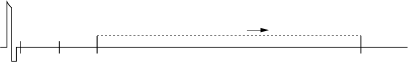
3-12 TACHYARRHYTHMIA DETECTION
VENTRICULAR DETECTION
• Post-shock Stability
• Post-shock SRD
• Post-shock Rhythm ID (uses AFib Rate Threshold, Stability, V Rate > A
Rate, and SRD)
With the exception of Rhythm ID, all post-shock detection enhancements
perform the same as the corresponding Initial Detection enhancements (with
Rhythm ID, Vector Timing and Correlation is not available post-shock).
Post-shock Stability may be used to prevent shock-induced AF from causing
the pulse generator to deliver undesired additional shocks (Figure 3-2 on
page 3-12.)
TheAFibRateThresholdcanbeprogrammedinconjunctionwithPost-shock
Stability to further discriminate AF and prevent the pulse generator from
delivering undesired ventricular shock therapy.
0 s 5 s 20 s
0 s 15 s
Lowest zone
detection window
satisfied.
Post-shock Duration = 5 s
Post-shock SRD = 15 s
Post-shock
Duration starts in
lowest zone.
Post-shock Duration
expires.
Evaluate Stability. If
stable, charge and
shock. If unstable, inhibit
therapy. Post-shock
SRD timer starts.
Continue Post-shock Stability
analysis throughout SRD time
as long as the detection
window remains satisfied.
If Stability indicates
therapy, charge and
shock.
Post-shock SRD times out.
Charge and deliver shock if
therapy had been inhibited
during SRD.
Shock
Figure 3-2. Post-shock Duration and Post-shock Stability analysis
Ventricular Detection Details
The pulse generator uses the following information to determine appropriate
therapy delivery:
• Ventricular detection windows
• Duration parameter
• Redetection duration and post-shock duration
• Ventricular episodes
• Ventricular detection enhancements
- DRAFT -
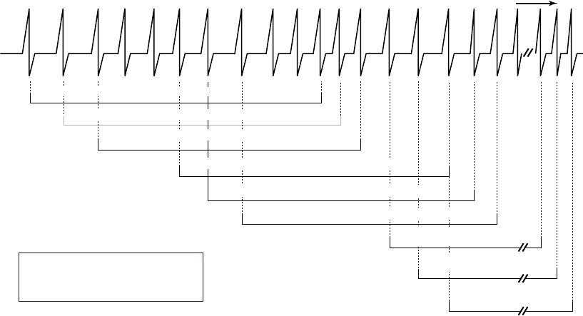
TACHYARRHYTHMIA DETECTION
VENTRICULAR DETECTION 3-13
Ventricular Detection Windows
Appropriate therapy delivery is dependent upon accurately classifying a
patient’s rhythm. To ensure that appropriate therapy is delivered, the pulse
generator employs detection windows to differentiate tachycardias.
Each ventricular zone has a detection window that consists of the 10 most
recent RV R–R intervals measured by the pulse generator. As each new
interval is measured, it is compared to each zone’s programmed rate threshold
and classified as either fast or slow (i.e., above or below the rate threshold) in
each detection window.
The pulse generator prepares for a potential episode when it counts 3
consecutive fast intervals. The detection window is satisfied and an episode is
declared when 8 out of 10 fast intervals are counted. The detection window
will remain satisfied as long as 6 of 10 intervals remain classified as fast. If the
number of fast intervals falls below 6, the zone’s detection window is no longer
satisfied. The zone’s detection window will only become resatisfiedwhen8of
10 intervals are again classified as fast (Figure 3-3 on page 3-13).
630 600 600 380 370 390 380 370 600 370 350 370 490 500 500 500 500 370
S S S S F F F F F F F F S S S S S F F
6 of 10 intervals are fast, VF window not satisfied.
8 of 10 intervals are fast, VF window is satisfied.
7 of 10 intervals are fast, VF window remains satisfied.
7 of 10 intervals are fast, VF window not satisfied.
6 of 10 intervals are fast, VF window remains satisfied.
5 of 10 intervals are fast, VF window is no longer satisfied.
6 of 10 intervals are fast, VF
window is not yet resatisfied
7 of 10 intervals are fast, VF
window is not yet resatisfied
8 of 10 intervals are fast, VF
window is resatisfied
VF
window
Intervals
in ms
VF Zone Rate = 150 min-1 (bpm) = 400 ms
S = Slow F = Fast
One-zone configuration
Right
Ventricle
Figure 3-3. Ventricular detection window satisfied
Because Rate Threshold in the higher zones must be programmed at a value
greater than Rate Threshold in lower zones, an interval classified as fast
- DRAFT -
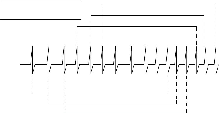
3-14 TACHYARRHYTHMIA DETECTION
VENTRICULAR DETECTION
in a higher window would also be classified as fast in any lower windows
(Figure 3-4 on page 3-14).
630 600 600 370 390 380 275 275 600 275 250 250
S S S S F F F F F F F F
240 240
F F
S S S S S S S F F F F F F F
240
F
F
VF Zone Rate = 200 min-1 (bpm) = 300 ms
VT Zone Rate = 150 min-1 (bpm) = 400 ms
S = Slow F = Fast
Intervals in ms
8 of 10 intervals are fast, VF window is satisfied.
7 of 10 intervals are fast, VF window not satisfied.
6 of 10 intervals are fast, VF window not satisfied.
8 of 10 intervals are fast, VT window is satisfied.
7 of 10 intervals are fast, VT window not satisfied.
6 of 10 intervals are fast, VT window not satisfied.
VF window
VT window
Figure 3-4. Interaction of ventricular detection windows, 2-zone configuration
Duration Parameter
The Duration parameter is a timer that measures the length of time in each
zone that a rhythm must be sustained before therapy is delivered.
A Duration timer begins when its respective zone’s detection window is
satisfied. The programmed Duration time is checked following every cardiac
cycle to determine if it has expired.
NOTE: Since the Duration timer is examined synchronously with a cardiac
cycle, the programmed Duration may be exceeded by up to one full cardiac
cycle.
• As long as the zone’s detection window remains satisfied, the Duration
timer continues to elapse. If the last detected interval is in the zone when
its Duration time expires, detection is considered met and therapy is
initiated (assuming no programmed detection enhancements inhibit therapy
delivery) (Figure 3-5 on page 3-15).
• If the last detected interval is not in the zone, therapy is not initiated. Each
subsequent interval will be checked until an interval is in the original zone,
or the window is no longer satisfied (Figure 3-6 on page 3-15).
- DRAFT -
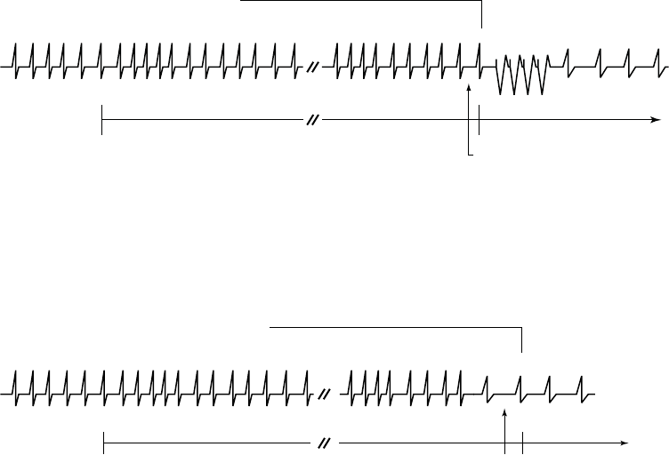
TACHYARRHYTHMIA DETECTION
VENTRICULAR DETECTION 3-15
• If at any point during Duration a zone’s detection window detects fewer
than 6 of 10 fast intervals, that zone’s Duration is reset to 0 (Figure 3-7 on
page 3-16). Duration will start again only if the detection window becomes
resatisfied.
VT detection window remains satisfied during
VT Duration.
VT Duration expires and the
next detected interval is in the
VT zone, detection is met.
ATP therapy is initiated.
VT window satisfied.
VT Duration starts.
VT Duration 1-30 s
VT detected
Right Ventricle
Duration starts when a window becomes satisfied and continues to elapse as long as the ventricular detection window
remains satisfied. Detection is met when Duration expires and the next detected interval is in the same ventricular
zone.
Figure 3-5. Ventricular Duration timer
VT detection window remains satisfied during
VT Duration.
VT Duration expires and the last
detected interval is not in the
same zone, detection in that
zone is not met. Therapy in that
zone is not initiated.
VT window satisfied.
VT Duration starts.
VT detected VT Duration 1-30 s
Right ventricle
Figure 3-6. Last detected interval
- DRAFT -
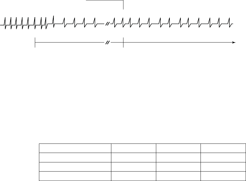
3-16 TACHYARRHYTHMIA DETECTION
VENTRICULAR DETECTION
VT detection window is no longer satisfied; fewer
than 6 of 10 intervals are classified as fast.
VT window satisfied.
VT Duration starts.
VT Duration resets to zero. VT Duration will start
again when the window becomes resatisfied.
Need 8 of 10 intervals classified as fast to restart VT Duration. VT Duration 1-30 seconds VT detected
Right ventricle
Duration resets when during the Duration period the window is no longer satisfied.
Figure 3-7. Ventricular Duration reset
A Duration is programmed for each ventricular zone. Different values are
available depending on the configuration programmed (Table 3-5 on page 3-16).
The Duration programmed in lower ventricular rate zones must be greater than
or equal to higher ventricular zones. Longer Durations may be used to prevent
the device from initiating treatment of non-sustained arrhythmias.
Table 3-5. Duration programmable ranges by ventricular zone and configuration
Configuration VT-1 ZoneaVT ZoneaVF Zoneb
1 Zone –– –– 1–15 seconds
2 Zones –– 1–30 seconds 1–15 seconds
3 Zones 1–60 seconds 1–30 seconds 1–15 seconds
a. The maximum redetect duration for the VT-1 and VT Zones is 15 seconds.
b. In the VF Zone, the redetect and post-shock duration is fixed at 1 second.
Duration in a Multi-zone Configuration
Duration timers run independently of each other within their respective
ventricular zones.
• If the arrhythmia is detected in the highest zone, that zone’s Duration timer
takes precedence over the lower zones’ timers; the lower zones’ Duration
timers continue to elapse but are ignored while the higher zone’s Duration
timer runs.
• If the higher zone’s Duration expires and detection is met, therapy for that
zone will be initiated regardless of whether the lower zones’ Duration
timers have expired.
- DRAFT -
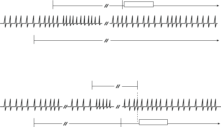
TACHYARRHYTHMIA DETECTION
VENTRICULAR DETECTION 3-17
• If the higher zone’s detection window does not remain satisfied, then the
Duration timers for the lower ventricular zones are no longer ignored.
Programmed therapy for lower ventricular zones will be initiated when a lower
ventricular zone’s duration is met and no higher ventricular zone’s window is
satisfied (Figure 3-8 on page 3-17, Figure 3-9 on page 3-17).
VF window satisfied.
VF Duration starts.
VF Duration 1 s
VF window remains satisfied. VF Duration expires
and detection is met. Charging begins. VT Duration
expires during charging, but is ignored.
Charging
VT window satisfied.
VT Duration starts.
VT detected VT Duration 5 s
VF detected
Figure 3-8. Interaction of ventricular Duration, 2-zone configuration, charging
VF window satisfied.
VF Duration starts.
VF window does not remain satisfied.
VF Duration is not satisfied.
VT Detection is met.
VT window satisfied.
VT Duration starts.
VT Duration expires. Detection is not met
because VF window is satisfied.
VT detected
VF detected
VF Duration 1 s
VT Duration 5 s
Charging
Figure 3-9. Interaction of ventricular Duration, 2-zone configuration, charging delayed
Ventricular Redetection Duration and Post-shock Duration
Duration parameters are used to identify tachyarrhythmias during the ventricular
redetection process.
• Redetection Duration is applied following delivery of ATP therapy (except
QUICK CONVERT ATP), a diverted-reconfirm, manually diverted therapy,
or if therapy is unavailable at Detection Met (Figure 3-10 on page 3-18).
• Post-shock Duration is applied following shock therapy delivery (Figure 3-11
on page 3-18).
- DRAFT -
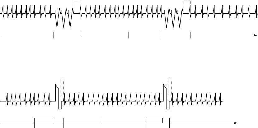
3-18 TACHYARRHYTHMIA DETECTION
VENTRICULAR DETECTION
Redetection Duration is programmable in the lower ventricular zones of a
multi-zone configuration. It is nonprogrammable in the VF Zone. Post-shock
Duration can be programmed in the same manner; the values programmed in
the lower ventricular rate zones must be greater than or equal to the values
programmed in the higher zones.
To help minimize time to potential therapy, it is recommended that Redetection
Duration in the VT-1 and VT zones of multi-zone configurations be programmed
at less than or equal to 5 seconds.
It is recommended that Post-shock Duration in the VT-1 and VT zones of
multi-zone configurationsalsobeprogrammedatlessthanorequalto5
seconds. However, you may program for longer durations if shock-induced,
non-sustained, high-rate rhythms, such as accelerated idioventricular rhythm
(AIVR) or AF are evident. The longer durations may allow the rhythm to return
to a lower rate before redetection is met.
3 s
8 of 10 intervals are
fast, window satisfied
Start
Redetection
Duration
Start
Redetection
A
TP therapy programmed.
Redetection Duration programmed at 3 s.
Initial Detection met
ATP therapy ATP therapy
Redetection
Duration expires.
Detection met.
Start Redetection
Look for 8 of 10 fast intervals
Ignored Ignored
Figure 3-10. Redetection following ventricular ATP delivery
3 s
Shock therapy programmed. Post-shock
Duration programmed at 3 s.
Initial Detection met Start Redetection Start Post-shock
Duration
Post-shock
Duration expires.
Detection met.
Start Redetection
Charging 8 intervals are fast Charging Look for 8 of 10 fast intervals
ShockShock
Ignored Ignored
Figure 3-11. Redetection following ventricular shock delivery
- DRAFT -

TACHYARRHYTHMIA DETECTION
VENTRICULAR DETECTION 3-19
Ventricular Episodes
If three consecutive fast ventricular beats are detected, then the pulse
generator performs the following:
• Increments the episode number
• Allocates memory for history data and electrogram storage
• Starts monitoring for a detection window to be satisfied
When any zone’s detection window becomes satisfied, the start of a ventricular
episode is declared and duration timers begin in those zones where detection
windows are satisfied. The ventricular episode is declared complete when all
detection windows are no longer satisfied and remain unsatisfied for a specified
time.
Each ventricular tachy episodes is classified as treated or non-treated
(Figure 3-12 on page 3-20 through Figure 3-16 on page 3-22).
• A treated episode is one in which therapy is delivered
• A nontreated episode is one in which no therapy is delivered
For a treated episode, an End-of-Episode timer starts after therapy is delivered.
For a non-treated episode, an End-of-Episode timer starts at the point that
the pulse generator recognizes that all detection windows are no longer
satisfied. The End-of-Episode time interval is intended to allow the patient
to stabilize before initial detection and initial therapy are used again. The
episode is declared complete if no detection window becomes satisfied for a
specified time following the last therapy attempt (Table 3-6 on page 3-19). If
any window becomes satisfied while the End-of-Episode timer is elapsing, the
End-of-Episode timer is reset to zero. It will start again when either therapy is
attempted or all windows are not satisfied (Figure 3-16 on page 3-22).
Once an episode has been declared complete, the pulse generator will apply
initial detection and therapy to subsequent tachyarrhythmias.
Table 3-6. End-of-Episode Timer
Episode Classification Ventricular End-of-Episode Timer
(elapsed time required to declare episode over)
Nontreated (no therapy delivered) 10 seconds
- DRAFT -
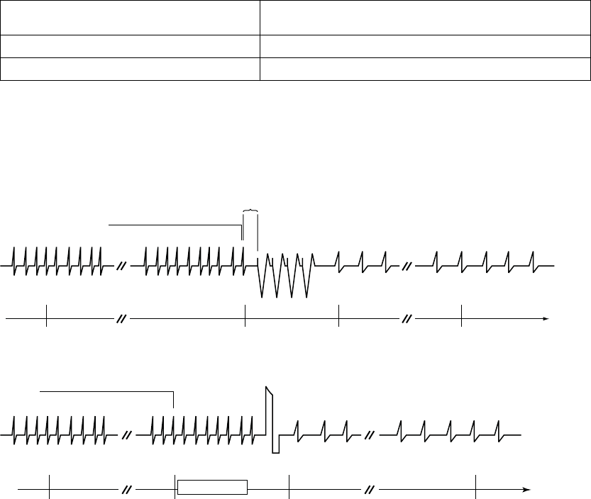
3-20 TACHYARRHYTHMIA DETECTION
VENTRICULAR DETECTION
Table 3-6. End-of-Episode Timer (continued)
Episode Classification Ventricular End-of-Episode Timer
(elapsed time required to declare episode over)
Treated (only ATP therapy delivered) 10 seconds
Treated (any shock therapy delivered) 30 seconds
NOTE: The episode is terminated immediately if the Tachy Mode is
reprogrammed, an induction method or lead test is attempted before the
End-of-Episode time out, or any ventricular detection or ventricular therapy
parameters are reprogrammed.
Coupling
Interval
Detection window does
not become satisfied.
End-of-Episode times out.
Episode is over.
Detection met.
Deliver ATP.
Start Duration.
Start episode.
Start End-of-
Episode timer.
Detection window remains satisfied.
ATP Burst 10 s
Detection window satisfied.
Figure 3-12. Treated episode, ventricular mode is Monitor + Therapy and ATP is delivered
Detection window remains satisfied.
Detection met.
Start Charging.
Start Duration.
Start episode.
Detection window satisfied.
Charging
Shock
End-of-Episode times out.
Episode is over.
Start End-of-Episode timer.
30 s
Detection window does not become satisfied.
Figure 3-13. Treated episode, ventricular mode is Monitor + Therapy and shock is delivered
- DRAFT -
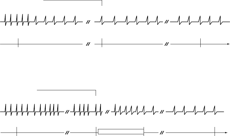
TACHYARRHYTHMIA DETECTION
VENTRICULAR DETECTION 3-21
Start Duration.
Start episode.
Duration did not expire.
Duration resets to zero.
Start End-of-Episode timer.
End-of-Episode times out.
Episode is over.
Detection window is no longer satisfied; fewer than 6
of 10 intervals are classified as fast.
Detection window satisfied.
10 s
Detection window does not become satisfied.
Figure 3-14. Nontreated episode, ventricular mode is Monitor + Therapy or Monitor Only, duration is not
expired
10 s
Ta chyarrhythmia spontan eously converts.
Reconfirmation monitors rhythm for five of ten
slow intervals during charging.
End-of-Episode
times out.
Episode is over.
Reconfirmation indicates
tachyarrhythmia not present;
shock not delivered. Start
End-of-Episode timer.
Start Duration.
Start episode.
Detection met.
Start Charging.
Detection window
satisfied.
F = Fast
S = Slow
Detection window remains satisfied.
FSSSSS
Charging
Right Ventricle
This example assumes Committed Shock is programmed to Off.
Figure 3-15. Nontreated episode, ventricular mode is Monitor + Therapy and charging is stopped prior
to shock delivery
- DRAFT -
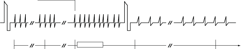
3-22 TACHYARRHYTHMIA DETECTION
VENTRICULAR DETECTION
Detection window
satisfied.
Start End-of-
Episode timer.
Start Post-shock
Duration
End-of-Episode
timer resets to zero.
Detection met.
Start Charging.
Restart End-of-Episode timer. End-of-Episode times
out. Episode is over.
Charging 30 s
Shock Shock
Ventricular rate
remains fast. Detection window does not become satisfied.
Right Ventricle
This example illustrates a Treated Episode when Ventricular mode is Monitor + Therapy. The End-of-Episode timer is
reset to 0 when a ventricular detection window becomes satisfied after ventricular therapy delivery, but prior to the
episode time-out being reached. In this example, 2 shocks were delivered in the episode.
Figure 3-16. Treated episode, ventricular mode is Monitor + Therapy and End-of-Episode timer is reset to 0
Ventricular Detection Enhancements
Ventricular detection enhancements add specificity to the Rate and Duration
detection criteria. You may program ventricular detection enhancements to
perform the following:
• Delay or inhibit therapy delivery
• Override therapy inhibition
• Bypass a sequence of ATP therapy in favor of shock therapy
Ventricular detection enhancements may be programmed to one of the
following:
•RhythmID
• Onset/Stability
• Off (i.e., rate only)
If Off is selected, only the ventricular rate and duration are used for therapy
decisions.
- DRAFT -

TACHYARRHYTHMIA DETECTION
VENTRICULAR DETECTION 3-23
If either Rhythm ID or Onset/Stability is selected, enhancement parameters are
used in addition to ventricular rate and duration for therapy decisions (Table 3-7
on page 3-23) as follows:
• Vector Timing and Correlation inhibits therapy when the conduction vector
(EGM morphology and timing) during tachyarrhythmia matches a reference
conduction vector of the patient’s normal sinus rhythm.
• VRate>ARatecanbeusedtooverridetheinhibitdecisionofOnset,
Stability, Vector Timing and Correlation, and/or AFib Rate Threshold. V
Rate > A Rate can be used to deliver ventricular therapy anytime the
ventricular rate is greater than the atrial rate.
• AFib Rate Threshold can be programmed (together with stability) to inhibit
ventricular therapy if the atrial rhythm is fast.
• Stability can be programmed to inhibit ventricular therapy delivery if the
ventricular rhythm is unstable.
• Shock if Unstable can be programmed to bypass the ventricular ATP
therapy and deliver shock therapy if the ventricular rhythm is declared
unstable.
• Onset can be programmed to inhibit ventricular therapy if the patient’s
heart rate increases gradually.
• SRD enables the pulse generator to override the Stability, Onset, Vector
Timing and Correlation, and/or AFib Rate Threshold parameters’ decision
to inhibit ventricular therapy if the high rate continues throughout the
programmed time period.
Table 3-7. Enhancement parameters available with detection enhancements
Rhythm ID Onset/Stability
Enhancement Parameter
Initial Post-Shock Initial Post-Shock
Vector Timing and CorrelationaX–– –– ––
V Rate > A Rate (dual-chamber devices only) Xbc Xbc XX
AFib Rate Threshold (dual-chamber devices only) Xbd Xbd XeXe
Stability (to inhibit) XfXfXX
Shock if Unstable –– –– X––
- DRAFT -

3-24 TACHYARRHYTHMIA DETECTION
VENTRICULAR DETECTION
Table 3-7. Enhancement parameters available with detection enhancements (continued)
Rhythm ID Onset/Stability
Enhancement Parameter
Initial Post-Shock Initial Post-Shock
Onset –– –– X––
SRDgXXXX
a. This enhancement is not individually programmable.
b. When Rhythm ID is selected, this enhancement is automatically enabled when Atrial Tachyarrhythmia Discrimination is
programmed to On. However, it is not available in single chamber devices or when the Atrial Tachyarrhythmia Discrimination is
programmed to Off in dual chamber devices.
c. This enhancement is not individually programmable when Rhythm ID is enabled.
d. When Rhythm ID is selected, this parameter uses the same value for both initial and post-shock detection. It cannot be
independently enabled or disabled for post-shock detection.
e. When Onset/Stability is selected, this parameter can be enabled and disabled independently for post-shock detection. If enabled,
it uses the same value as the initial detection.
f. When Rhythm ID is enabled and Atrial Tachyarrhythmia Discrimination is programmed to On in dual chamber devices, this
enhancement uses the same value for both initial and post-shock detection. In single chamber devices, or when Atrial
Tachyarrhythmia Discrimination is programmed to Off, this enhancement is automatically disabled for Initial Detection, but is still
enabled for post-shock detection.
g. SRD is available when detection enhancements, which inhibit therapy, are programmed.
Some of these detection enhancement parameters are also independently
programmable as post-shock parameters (Table 3-7 on page 3-23).
The individual detection enhancement parameters that are available depend
on the number of tachy zones that are programmed: 3, 2, or 1 (Table 3-8 on
page 3-24).
Table 3-8. Individual Ventricular Detection Enhancements available in multizone configurations
VT-1 Zone VT Zone VF Zone
Vector Timing and
Correlation
Vector Timing and
Correlationa
V Rate > A Rate V Rate > A Ratea
AFib Rate Threshold AFib Rate Thresholda
Stability to Inhibit Stability (to Inhibit)a
Onset Shock if Unstable
3-zone configuration
SRD SRDa
––
- DRAFT -

TACHYARRHYTHMIA DETECTION
VENTRICULAR DETECTION 3-25
Table 3-8. Individual Ventricular Detection Enhancements available in multizone configurations (continued)
VT-1 Zone VT Zone VF Zone
Vector Timing and Correlation
V Rate > A Rate
AFib Rate Threshold
Stability (to Inhibit)
Shock if Unstablec
Onset
3-zone configuration
(with Monitor Only zone)b
––
SRD
––
Vector Timing and Correlation
V Rate > A Rate
AFib Rate Threshold
Stability (to Inhibit)
Shock if Unstablec
Onset
2-zone configuration
SRD
––
2-zone configuration (with Monitor Only zone)b–– ––
1-zone configuration ––
a. Enhancement is available in the middle zone of a 3-zone configuration only when Rhythm ID is enabled.
b. Detection enhancements are not available in the lowest zone of a multi-zone configuration when it is used as a Monitor Only
zone (no therapy programmed for that zone).
c. Shock if Unstable cannot be programmed on in the same zone as other detection enhancements that are programmed to
inhibit therapy (Onset, Stability, and AFib Rate Threshold).
When a specific rhythm discrimination is selected, preselected values are
displayed for the detection enhancements that are suitable for discriminating
that rhythm. However, you can modify those values at your discretion (Table 3-9
on page 3-26).
- DRAFT -

3-26 TACHYARRHYTHMIA DETECTION
VENTRICULAR DETECTION
Table 3-9. Preselected values for initial detection and redetection enhancements
Onset/Stability Rhythm ID
Parameter Atrial
Tachyarrhythmia
Discrimination
Sinus
Tachycardia
Discrimination
Polymorphic
VT
Discrimination
Atrial
Tachyarrhythmia
Discrimination
On
Atrial
Tachyarrhythmia
Discrimination
Off
Vector
Timing and
Correlation
–– –– –– OnaOna
VRate>
ARate
(dual-chamber
models
only)
On On –– Onb––
AFib Rate
Threshold
(dual-chamber
models
only)
170 bpm –– –– 170 bpm ––
Stability
(Inhibit)
20 ms
(DR devices)
30 ms
(VR devices)
–– –– 20 ms
(DR devices)
30 ms
(VR devices)
30 ms
Onset
(initial
detection
only)
–– 9% –– –– ––
SRD Initial 3:00
minutes:seconds
3:00
minutes:seconds
–– 3:00
minutes:seconds
3:00
minutes:seconds
SRD
Redetection
0:15
minutes:seconds
–– –– 0:15
minutes:seconds
0:15
minutes:seconds
Shock if
Unstable
–– –– 30 ms –– ––
a. Parameter is not individually programmable.
b. Parameter is not individually programmable when Rhythm ID is enabled.
Vector Timing and Correlation
Vector Timing and Correlation compares EGM signals for an unknown rhythm
with a stored reference template of the EGM signals of a normal sinus rhythm
(NSR). Rhythms that are not similar to the reference template (are not
correlated) are classified as VT. Rhythms that are correlated with the reference
template are classified as SVT.
When an unknown fast rhythm is sensed in the VT or VT-1 zones, each beat
of the fast rhythm is compared to the stored reference template. The pulse
- DRAFT -
TACHYARRHYTHMIA DETECTION
VENTRICULAR DETECTION 3-27
generator calculates a Feature Correlation Coefficient and makes the following
therapy decisions based on the calculation:
• If at least 3 out of 10 beats are correlated, the rhythm is classified as SVT
• If fewer than 3 out of 10 beats are correlated, the rhythm is classified as VT
Rhythm ID makes its decision to treat or inhibit therapy at the end of Duration. If
the decision is made to inhibit therapy, Rhythm ID (including Vector Timing and
Correlation, V Rate > A Rate, AFib Rate Threshold, and Stability) continues
to be recalculated beat-by-beat throughout SRD.
V Rate > A Rate
The V Rate > A Rate (ventricular rate greater than atrial rate) enhancement
compares the atrial and ventricular rates to classify the type of fast ventricular
rhythm. When the ventricular rate is greater than the atrial rate, therapy will
be initiated regardless of the analysis of the other programmed detection
enhancements.
Analysis is made by comparing the average rate of the last 10 ventricular
intervals prior to the end of Duration to the average rate of the last 10 atrial
intervals prior to the end of Duration (Figure 3-17 on page 3-28). If fewer than
10 atrial intervals are available, those intervals will be used to calculate the
average atrial rate. This analysis is performed using the following criteria:
• If the average ventricular rate is greater than the average atrial rate by at
least 10 bpm, the ventricular rate is declared to be faster than the atrial
rate (indicated as True on the Episode Detail Report), and therapy will
be initiated.
• If the average ventricular rate is not greater than the average atrial rate by
at least 10 bpm (indicated as False on the Episode Detail Report), therapy
may continue to be inhibited. The Episode Detail report will indicate the
measured value even though the parameter may be programmed to Off.
If therapy is inhibited, the V Rate > A Rate analysis continues until either the
ventricular rate is greater than the atrial rate or other enhancements indicate
therapy treatment, at which time therapy will be initiated.
NOTE: V Rate > A Rate is not evaluated during redetection following ATP
therapy.
- DRAFT -
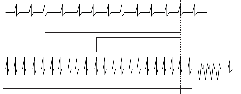
3-28 TACHYARRHYTHMIA DETECTION
VENTRICULAR DETECTION
400 380 420 390 410 400 360 440 410 390
580 620 600 640 560 600 580 600 620
1 2 3 4 5 6 7 8 9
1 2 3 4 5 6 7 8
Number of
Intervals
Intervals
in ms
Third fast interval (of the 8 out
of 10 that satisfy the detection
window)
Start Duration.
Evaluate Onset.
Compute the sum of 10 most recent ventricular
intervals. Average = 400 ms = 150 min-1 (bpm).
Duration expired.
Onset is gradual.
Analyze V Rate > A Rate.
Deliver therapy because V > A.
Average ventricular rate (150 min-1
[bpm]) is greater than average
atrial rate (100 min-1 [bpm]) by at
least 10 bpm, so delivery therapy.
Compute the sum of the atrial intervals.
Average = 600 ms = 100 min-1 (bpm).
Number of Intervals
Intervals in
ms
A
trium
Ventricle
VT detected
ATP therapy
Figure 3-17. V Rate > A Rate analysis
V Rate > A Rate can be programmed to bypass inhibitors (Vector Timing and
Correlation, AFib Rate Threshold, Stability, and/or Onset) and initiate therapy in
the event that the ventricular rate is faster than the atrial rate.
NOTE: Refer to "Use of Atrial Information" on page 3-5 for additional
information about device performance when the atrial lead is programmed to
Off.
NOTE: In a Rhythm ID configuration, the evaluation of V Rate > A Rate is
linked to the AFib Rate Threshold. If Atrial Tachyarrhythmia Discrimination is
programmed to Off, the AFib Rate Threshold and V Rate > A Rate detection
enhancements are not evaluated.
AFib Rate Threshold
AFib Rate Threshold analysis identifies AF by comparing the atrial rate to the
programmed AFib Rate Threshold.
AFib Rate Threshold cannot be enabled without also enabling the Stability
detection enhancement. The device analyzes both parameters to determine
whether to withhold or deliver therapy.
If the intrinsic atrial rate is greater than the AFib Rate Threshold and the
ventricular rhythm is classified as unstable, the ventricular rhythm is declared
to be due to AF.
- DRAFT -
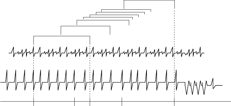
TACHYARRHYTHMIA DETECTION
VENTRICULAR DETECTION 3-29
The intrinsic atrial rate is declared to be above the AFib Rate Threshold in the
following manner (Figure 3-18 on page 3-29):
• Atrial analysis begins at initiation of ventricular tachyarrhythmia detection.
Each atrial interval is classified as faster or slower than the AFib Rate
Threshold Interval.
• When 6 of the last 10 intervals are classified as faster than the AFib Rate
Threshold, the device declares AF to be present.
• Ventricular stability is then checked. If unstable, therapy is inhibited.
In the event that ventricular therapy is not delivered, the atrial rate continues
to be examined. As long as 4 of 10 intervals remain classified as fast, AF
is considered present. Therapy is inhibited by AFib Rate Threshold/Stability
until any of the following occur:
• The atrial rate drops below the AFib Rate Threshold
• The ventricular rhythm becomes stable
• IfprogrammedtoOn,VRate>ARateistrue
•SRDtimesout
12345678
Only 3 of 10 intervals are
above the AFib Rate Threshold
4 of 10 > AFib Rate Threshold
4 of 10 intervals must remain
> AFib Rate Threshold
6 of 10 atrial intervals are greater
than AFib Rate Threshold
Third fast interval (of the 8
out of 10 that satisfy the
detection window)
Detection satisfied.
Start duration.
Start episode.
Start Stability analysis.
Atrial rate >
AFib Rate
Threshold.
Duration expires.
Atrial rate > AFib Rate Threshold.
Rhythm declared unstable.
Therapy is inhibited.
Rhythm remains unstable.
Atrial rate is less than
AFib Rate Threshold.
Initiate therapy.
ATP therapy
VT detected
Ventricle
Atrium
Figure 3-18. Interaction of AFib Rate Threshold and Stability
- DRAFT -

3-30 TACHYARRHYTHMIA DETECTION
VENTRICULAR DETECTION
When AFib Rate Threshold and Stability are used alone, ventricular therapy
is initiated when a stable rhythm is declared. Ventricular therapy is initiated
for an unstable rhythm when it is determined that the atrial rate is less
than the AFib Rate Threshold (Table 3-10 on page 3-30). When AFib
Rate Threshold and Stability are used with other inhibitor enhancements,
ventricular therapy is not always initiated when no longer inhibited by AFib Rate
Threshold/Stability. Therapy may continue to be inhibited by other programmed
detection enhancements, such as Onset (when the Onset/Stability detection
enhancement suite is enabled) or Vector Timing and Correlation (when the
Rhythm ID detection enhancement suite is enabled).
Consider the following information during these interactions:
• The AFib Rate Threshold and V Rate > A Rate detection enhancements
are not evaluated if Atrial Tachyarrhythmia Discrimination is programmed to
Off in a Rhythm ID configuration.
• Because the AFib Rate Threshold is not evaluated during redetection
(following ventricular ATP therapy delivery, any aborted ventricular therapy,
or therapy not available), the Episode Detail report will not display data
for the enhancement during redetection, even though the parameter is
programmed On.
• The AFib Rate Threshold enhancement is not evaluated for arrhythmia
detection in the following cases; however, the Episode Detail report will still
display the data for the AFib Rate Threshold enhancement based on a
threshold of 170 bpm:
– The AFib Rate Threshold is programmed to Off
– Ventricular Zones is programmed to 1
– No detection enhancement suite is enabled
• An atrial sense event will only be classifiedasAFwhiletheAFibRate
Threshold is being evaluated for arrhythmia detection.
Table 3-10. AFib Rate Threshold and Stability combinations and resulting therapy
Detected Ventricular RhythmaTherapy Decisionb
Unstable, A > AFib Rate Threshold Inhibit
Stable, A > AFib Rate Threshold Treat
- DRAFT -

TACHYARRHYTHMIA DETECTION
VENTRICULAR DETECTION 3-31
Table 3-10. AFib Rate Threshold and Stability combinations and resulting therapy (continued)
Detected Ventricular RhythmaTherapy Decisionb
Unstable, A < AFib Rate Threshold Treat
Stable, A < AFib Rate Threshold Treat
a. If the detected ventricular rhythm changes, then the appropriate, corresponding row in the table is evaluated.
b. Decisions to inhibit can be overridden by V > A or expiration of SRD.
NOTE: Refer to "Use of Atrial Information" on page 3-5 for additional
information about device performance when the atrial lead is programmed to
Off.
Stability Analysis
Stability analysis distinguishes unstable (irregular) ventricular rhythms from
stable (regular) ventricular rhythms. This is accomplished by measuring the
degree of variability of the tachycardia R–R intervals.
This degree of variability, when used alone, may allow the device to distinguish
conducted AF (which may produce greater R–R variability) from monomorphic
VT (which is typically stable). It also may be used to differentiate MVTs (which
are pace terminable) from polymorphic VTs and VF (which are typically not
pace terminable).
Based on the patient’s needs, you may choose to program Stability as an
inhibitor to prevent therapy for AF, or use stability analysis to direct the type of
therapy to be delivered (Shock if Unstable).
The stability algorithm calculates RV R–R interval differences. These
differences are calculated throughout Duration; an average difference is also
calculated. When Duration expires, rhythm stability is evaluated by comparing
the current average difference to the programmed Stability threshold and/or
Shock If Unstable thresholds. If the average difference is greater than the
programmed thresholds, the rhythm is declared unstable. Independent
thresholds are available for the Stability (to inhibit) or Shock If Unstable
functions; you cannot program both in the same ventricular zone.
The pulse generator performs stability calculations for all episodes (even when
Stability is programmed to Off) and stores the results in therapy history. This
stored data may be used to select an appropriate stability threshold.
- DRAFT -
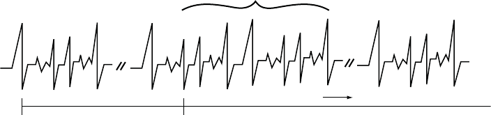
3-32 TACHYARRHYTHMIA DETECTION
VENTRICULAR DETECTION
Stability to Inhibit
The Stability parameter may help you identify rapid rhythms originating in the
atrium, such as AF. These rhythms may result in unstable ventricular rhythms
whose rate exceeds the lowest rate threshold and should not be treated. If a
rhythm is declared stable when Duration expires, programmed therapy will
be delivered. If the rhythm is declared unstable, ventricular therapy will be
inhibited.
At the end of initial Duration, if a tachycardia is declared unstable and
ventricular therapy is inhibited, the pulse generator continues to evaluate for
stability on each new detected interval (Figure 3-19 on page 3-32). Therapy will
not be inhibited by Stability if:
• V Rate > A Rate declares the ventricular rate greater than the atrial rate
• The SRD has expired (if programmed to On)
Ventricular therapy is not always initiated when no longer inhibited by
Stability. Therapy may continue to be inhibited by other programmed
detection enhancements, such as Onset (when the Onset/Stability detection
enhancement suite is enabled) or Vector Timing and Correlation (when the
Rhythm ID detection enhancement suite is enabled).
NOTE: Ventricular Therapy can also be inhibited through analysis of the
Stability algorithm as it is used with the AFib Rate Threshold enhancement.
Unstable intervals
Detection window satisfied.
Start Duration.
Stability analysis begins.
Duration expires.
Rhythm declared unstable.
Start SRD.
Therapy inhibited until rhythm stabilizes, V is greater
than A, or SRD times out.
Stability analysis continues
Figure 3-19. Stability evaluation when Duration expires
- DRAFT -
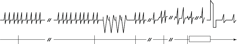
TACHYARRHYTHMIA DETECTION
VENTRICULAR DETECTION 3-33
Shock if Unstable
When programmed to Shock if Unstable, the stability analysis helps determine
if ventricular ATP therapy should be bypassed in preference for the first
programmed ventricular shock therapy (which may be low- or high-energy) for
the ventricular zone (Figure 3-20 on page 3-33).
Dynamic ventricular arrhythmias such as polymorphic VT or VF may be sensed
at a rate lower than the highest ventricular rate threshold and can be classified
as unstable. Since the sensed rhythm may be detected in a lower ventricular
zone in which ATP may be programmed, the stability analysis may be used
to skip over the programmed ventricular ATP therapies and instead provide
shocks to the patient. Stability is evaluated on each detection/redetection cycle,
including evaluation between bursts of an ATP scheme. Once a ventricular
shock has been delivered in an episode, the Shock If Unstable function no
longer affects therapy selection.
Shock If Unstable may be used only in the VT zone of a 2- or 3-zone
configuration. You cannot program it in a 2-zone configuration if Stability or
Onset is already programmed to On, or if Post V-Shock Stability or AFib Rate
ThresholdisprogrammedtoOn.
Detection window satisfied.
Start Duration.
Stability analysis begins.
Duration expires.
Rhythm declared stable.
Deliver programmed ATP
therapy.
Start
Redetection.
Detection window
satisfied.
Start Redetection
Duration.
Reanalyze Stability.
Redetection Duration expires.
Rhythm declared unstable.
Skip remaining ATP and
proceed to the first
programmed shock therapy.
Charging
Shock
ATP Burst
Figure 3-20. Shock if Unstable
Onset
Onset differentiates physiologic sinus tachycardias, which typically begin
slowly, from pathologic tachycardias, which typically begin abruptly. It measures
the rate of transition in the ventricular rhythm from slow rates to tachycardia. If
the rate increase is gradual, it enables the device to inhibit ventricular therapy
in the lowest tachycardia rate zone.
- DRAFT -
3-34 TACHYARRHYTHMIA DETECTION
VENTRICULAR DETECTION
When a detection window becomes satisfied, the pulse generator begins
calculating for sudden Onset in a two-stage sequence.
• Stage 1 measures the ventricular intervals prior to the start of the episode
and locates the pair of adjacent intervals (pivot point) where the cycle
length decreased the most. If the decrease in cycle length is equal to or
greater than the programmed Onset value, stage 1 declares sudden Onset.
• Stage 2 then compares additional intervals. If the difference between the
average interval before the pivot point and 3 out of the first 4 intervals
following the pivot point is equal to or greater than the programmed Onset
Threshold, stage 2 declares sudden Onset.
If both stages declare the rhythm sudden, therapy will be initiated. If either
stage indicates a gradual onset, initial ventricular therapy will be inhibited in the
lowest zone. Therapy will not be inhibited by Onset if:
• The rate accelerates to a higher ventricular zone
• Information from the atrial lead determines that the RV rate is faster than
theatrialrate(VRate>ARateprogrammedtoOn)
• The SRD timer expires
Onset is measured using RV intervals only. It can be programmed as a
percentage of cycle length or as an interval length (in ms). It is limited to the
lowest therapy zone of a multi-zone configuration. The selected Onset value
represents the minimum difference that must exist between intervals that are
above and below the lowest programmed rate threshold. The pulse generator
performs Onset calculations (even when the feature is programmed to Off) for
all episodes except induced or commanded episodes. The measured Onset
results from a two-stage calculation are stored in therapy history. This stored
data may be used to program an appropriate Onset value.
Sustained Rate Duration (SRD)
Sustained Rate Duration allows delivery of the programmed ventricular therapy
when a tachycardia is sustained for a programmed period beyond Duration, but
the programmed therapy inhibitors (Vector Timing and Correlation, AFib Rate
Threshold, Onset, and/or Stability) indicate to withhold therapy (Figure 3-21 on
page 3-35).
- DRAFT -

TACHYARRHYTHMIA DETECTION
VENTRICULAR DETECTION 3-35
0 s 5 s 35 s
0 s 30 s
Duration = 5 seconds
SRD = 30 seconds
Evaluate programmed detection
enhancements. If enhancements
indicate to inhibit therapy, start
SRD timer; otherwise, deliver
therapy.
Continue detection
enhancement
analysis throughout
SRD time.
If detection
enhancements
indicate therapy,
deliver therapy.
SRD times out.
Deliver therapy.
Detection window
satisfied
Duration starts. Start
detection enhancement
analysis.
Duration expires.
Figure 3-21. Combination of Onset OR Stability, SRD programmed on
SRD is available in a zone only when an inhibitor enhancement is programmed
on in that zone. When the Rhythm ID detection enhancement suite is enabled,
SRD may be programmed separately for the VT and VT-1 zones.
• If an inhibitor is withholding ventricular therapy delivery and the Rate
criterion in the lowest zone is maintained, the programmed SRD timer
begins at the end of the first zone’s completed Duration.
• If the detection window in the lowest zone is maintained for the programmed
SRD period, the programmed ventricular therapy will be delivered at the
end of the VT-1 SRD period if VT-1 SRD is programmed and the rhythm
is in the VT-1 zone. Therapy will be delivered at the end of the VT SRD
period if VT SRD is programmed and the rhythm is in the VT zone.
• If the rate accelerates to a higher ventricular zone, detection enhancements
are not programmed to On in the higher zone, and the Duration for the
higher zone expires, therapy is initiated in that zone without waiting for
SRD time-out in a lower ventricular zone. If SRD is programmed to Off,
an SRD timer will not start when Duration expires, thus allowing detection
enhancements to potentially inhibit therapy indefinitely.
An independent Post-Shock SRD value may be programmed.
Combinations of AFib Rate Threshold, Stability, and Vector Timing and
Correlation
The combination of AFib Rate Threshold, Stability, and Vector Timing and
Correlation add specificity to ventricular detection beyond rate and duration.
In addition to using AFib Rate Threshold and Stability to identify AF, this
combination of enhancements uses Vector Timing and Correlation analysis
to differentiate SVT rhythms from VT rhythms based on conduction patterns
within the heart.
- DRAFT -

3-36 TACHYARRHYTHMIA DETECTION
VENTRICULAR DETECTION
The AFib Rate Threshold, Stability, and Vector Timing and Correlation detection
enhancement combination also includes V Rate > A Rate; both AFib Rate
Threshold and V Rate > A Rate are enabled when Atrial Tachyarrhythmia
Discrimination is programmed to On. This combination is only available when
the Rhythm ID detection enhancement suite is enabled, and only for Initial
Detection(Table3-11onpage3-36).
If V Rate > A Rate is programmed to On (by programming Atrial
Tachyarrhythmia Discrimination to On) and is True, it will take precedence over
all inhibitor enhancements.
Table 3-11. AFib Rate Threshold, Stability, and Vector Timing and Correlation combinations and resulting
therapy decision if Atrial Tachyarrhythmia Discrimination is programmed to On
Detected Ventricular Rhythmabc Therapy Decisiond
Correlated, Unstable, A > AFib Rate Threshold Inhibit
Correlated, Unstable, A < AFib Rate Threshold Inhibit
Uncorrelated, Unstable, A > AFib Rate Threshold Inhibit
Uncorrelated, Unstable, A < AFib Rate Threshold Treat
Correlated, Stable, A > AFib Rate Threshold Inhibit
Correlated, Stable, A < AFib Rate Threshold Inhibit
Uncorrelated, Stable, A > AFib Rate Threshold Treat
Uncorrelated, Stable, A < AFib Rate Threshold Treat
a. If the detected ventricular rhythm changes, then the appropriate, corresponding row in the table is evaluated.
b. If a Rhythm ID reference template is not available, the detected ventricular rhythm is considered to be Uncorrelated.
c. For post shock detection (if enabled), Vector Timing and Correlation is considered to be Uncorrelated.
d. Decisions to inhibit can be overridden by V > A or expiration of SRD.
When Atrial Tachyarrhythmia Discrimination is programmed to Off, then Vector
Timing and Correlation is used for Initial Detection and Stability is used for
Post-shock detection. V Rate > A Rate and AFib Rate Threshold are no longer
used (Table 3-12 on page 3-36).
Table 3-12. Vector Timing and Correlation and Stability combinations with resulting therapy decision if Atrial
Tachyarrythmia Discrimination is programmed to Off
Detectionab Dectected Ventricular
Rhythmac
Therapy Decision
Initial Correlated Inhibitd
Initial Uncorrelated Treat
- DRAFT -

TACHYARRHYTHMIA DETECTION
VENTRICULAR DETECTION 3-37
Table 3-12. Vector Timing and Correlation and Stability combinations with resulting therapy decision if Atrial
Tachyarrythmia Discrimination is programmed to Off (continued)
Detectionab Dectected Ventricular
Rhythmac
Therapy Decision
Post-shock Unstable Inhibitd
Post-shock Stable Treat
a. If the detected ventricular rhythm changes, then the appropriate, corresponding row in the table is evaluated.
b. If Atrial Tachyarrhythmia Discrimination is programmed to Off, then Vector Timing and Correlation is used for Initial Detection,
and Stability is used for Postshock Detection.
c. If a Rhythm ID reference template is not available, the detected ventricular rhythm is considered to be Uncorrelated.
d. Decision to inhibit can be overridden by expiration of SRD.
Combinations of AFib Rate Threshold, Stability, and Onset
The combination of AFib Rate Threshold, Stability, and Onset add specificity
to ventricular detection beyond rate and duration. This combination of
detection enhancements is available only when the Onset/Stability detection
enhancement suite is enabled and is available only for Initial Detection. When
detection enhancements are enabled, they will act to recommend or inhibit
therapy for a specific zone.
If AFib Rate Threshold, Stability, and Onset parameters are all programmed
to On, ventricular therapy will be initiated if the rhythm has a sudden onset
provided that either the ventricular rate is stable or the atrial rate is less than
the AFib Rate Threshold (Table 3-13 on page 3-37).
Table 3-13. AFib Rate Threshold, Stability, and Onset combinations and resulting ventricular therapy
Detected Ventricular RhythmaTherapy Decisionb
Gradual, Unstable, A > AFib Rate
Threshold
Inhibit
Gradual, Unstable, A < AFib Rate
Threshold
Inhibit
Sudden, Unstable, A > AFib Rate
Threshold
Inhibit
Sudden, Unstable, A < AFib Rate
Threshold
Treatc
Gradual, Stable, A > AFib Rate Threshold Treat
Gradual, Stable, A < AFib Rate Threshold Inhibit
Sudden, Stable, A > A Fib Rate Threshold Treat
Sudden, Stable, A < AFib Rate Threshold Treat
a. If the detected ventricular rhythm changes, then the appropriate, corresponding row in the table is evaluated.
b. Decisions to inhibit can be overridden by V > A or expiration of SRD.
c. If V Rate > A Rate is programmed to On and is False, ventricular therapy will be inhibited because the rhythm is unstable.
- DRAFT -
3-38 TACHYARRHYTHMIA DETECTION
VENTRICULAR DETECTION
If V Rate > A Rate is programmed to On and is True, it will take precedence
over all inhibitor enhancements.
Combinations of Onset and Stability
When Stability is programmed to inhibit, it may be combined with Onset to
provide even greater specificity in classifying arrhythmias.
This combination of detection enhancements is available only when the
Onset/Stability detection enhancement suite is enabled and is available only for
Initial Detection. The enhancements can be programmed to initiate ventricular
therapy if the following options are selected (Table 3-14 on page 3-38):
• Both Onset And Stability indicate to treat
• Either Onset Or Stability indicates to treat
Based on these programming decisions, ventricular therapy is inhibited when
any of the following criteria is met:
• If the combination programmed is Onset And Stability, ventricular therapy
is inhibited if either parameter indicates that therapy should be withheld;
that is, the rhythm is gradual Or unstable (the And condition to treat is
not satisfied).
• If the combination programmed is Onset Or Stability, ventricular therapy is
inhibited immediately at the end of Duration only if both parameters indicate
that therapy should be withheld; that is, the rhythm is gradual and unstable
(the Or condition to treat is not satisfied).
In either case, ventricular therapy will be initiated only if the And/Or conditions
to treat are satisfied. When these two combinations (And/Or) are used in
conjunction with SRD, and the And/Or conditions are not satisfied, ventricular
therapy will be inhibited until V Rate > A Rate is True or SRD times out
(Table 3-14 on page 3-38).
Table 3-14. Combinations of Onset And Stability and resulting therapy
Detection
Rhythm
Onset And Stability Combinationab Onset Or Stability Combinationc
Gradual, unstable Inhibit Inhibit
Gradual, stable Inhibit Treat
- DRAFT -

TACHYARRHYTHMIA DETECTION
VENTRICULAR DETECTION 3-39
Table 3-14. Combinations of Onset And Stability and resulting therapy (continued)
Detection
Rhythm
Onset And Stability Combinationab Onset Or Stability Combinationc
Sudden, unstable Inhibit Treat
Sudden, stable Treat Treat
a. If the detected ventricular rhythm changes, then the appropriate, corresponding row in the table is evaluated.
b. The And combination is the nominal setting when both are enabled.
c. Decisions to inhibit can be overridden by V > A or expiration of SRD.
- DRAFT -
3-40 TACHYARRHYTHMIA DETECTION
VENTRICULAR DETECTION
- DRAFT -

4-1
TACHYARRHYTHMIA THERAPY
CHAPTER 4
This chapter contains the following topics:
• "Ventricular Therapy" on page 4-2
• "Antitachycardia Pacing Therapies and Parameters" on page 4-10
• "Ventricular Shock Therapy and Parameters" on page 4-21
- DRAFT -
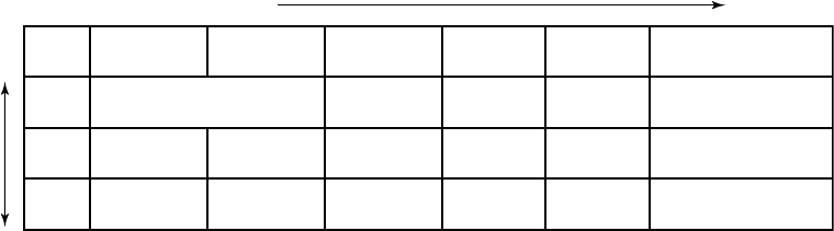
4-2 TACHYARRHYTHMIA THERAPY
VENTRICULAR THERAPY
VENTRICULAR THERAPY
The pulse generator can deliver the following types of therapy to terminate
VT or VF:
• Antitachycardia pacing (ATP)
• Cardioversion/defibrillation shocks
ATP pacing schemes are bursts of pacing pulses delivered between the
ventricular pace/sense electrodes. Shocks are high-voltage biphasic pulses
delivered through the shocking electrodes synchronously with detected heart
activity.
Ventricular Therapy Prescription
A ventricular therapy prescription determines the type of therapy to be
delivered in a particular ventricular rate zone. It consists of ventricular ATP
and/or shocks. Each ventricular zone may be programmed with independent
ventricular therapy prescriptions (Figure 4-1 on page 4-2).
Lowest strength Highest strength
Wi
t
hi
n eac
h
zone, t
h
erapy strengt
h
must
b
e
i
n ascen
di
ng or
d
er.
Zone ATP12 ATP22 QUICK
CONVERT ATP
Shock 11 Shock 21 Remaining (Maximum)
Shocks1
VF
VT
VT-1
Not available
All ATP types
available
On/Off
N/A
N/A
0.1-max J
0.1-max J
0.1-max J
0.1-max J
0.1-max J
0.1-max J
max J
max J
max J
All ATP types
available
All ATP types
available
All ATP types
available
Between
zones,
therapy
strengths
are not
restricted.
1 In the lowest zone of a multi-zone configuration, some or all of the shocks may be programmed to Off, starting with the maximum shocks
first. If the maximum shocks are programmed to Off, then Shock 2 can be programmed to Off. If Shock 2 is programmed to Off, then
Shock 1 can be programmed to Off. If the arrhythmia persists in the lowest zone when some or all of the shocks are programmed to Off,
no further therapy will be delivered unless the arrhythmia accelerates to a higher zone. A Disable Therapy button is available in the VT or
VT-1 zones’ therapy window to quickly disable all ATP and Shock therapy in that zone.
2 Ventricular ATP therapy can be programmed as Off, Burst, Ramp, Scan, or Ramp/Scan in VT-1 and VT zones.
Figure 4-1. Ventricular therapy prescription, 3-zone configuration
The therapies within a ventricular zone must be ordered in ascending therapy
strengths. All ventricular ATP therapies are considered to be of equal strength,
but are of lower strength than any shock therapy. The strength of the
shock therapies is determined by the programmed energy. In a multi-zone
configuration, therapies in a higher ventricular zone may be of lesser, greater,
or equal strength to those in a lower ventricular zone; however, within each
zone the therapies must be programmed in equal or increasing energy output.
- DRAFT -
TACHYARRHYTHMIA THERAPY
VENTRICULAR THERAPY 4-3
Ventricular Therapy Selection
The pulse generator determines which ventricular therapy to deliver based
on the following rules:
• Each successive therapy delivery must be greater than or equal to the
strength of the previous therapy in a ventricular episode. Whenever a
ventricular shock therapy has been delivered, no further ventricular ATP
therapy is allowed in that episode since ATP therapy is of lower strength
than shock therapy. Each subsequent ventricular shock delivery must be of
equal or greater strength regardless of ventricular zone changes during a
ventricular episode.
• Each ventricular ATP scheme (which may consist of multiple bursts) can
only be delivered once during a ventricular episode.
• Up to 8 shocks may be delivered in a ventricular episode. The first 2 shocks
are programmable. The following maximum-energy, non-programmable
shocks are available in each zone:
– VT-1 zone: 3 maximum-energy shocks
– VT zone: 4 maximum-energy shocks
– VF zone: 6 maximum-energy shocks
NOTE: In the event a shock is diverted with the DIVERT THERAPY
programmer command, by magnet application or due to a Diverted-Reconfirm,
the diverted shock is not counted as one of the available shocks for that
tachyarrhythmia episode. Also, commanded therapies and STAT SHOCK are
not counted as one of the available shocks for an episode and do not affect
subsequent therapy selection.
Based on initial ventricular detection criteria, the pulse generator selects the
first prescribed therapy in the ventricular zone in which the tachyarrhythmia
is detected (i.e., detection is met; see "Ventricular Detection" on page 3-6).
After delivering the selected therapy, the pulse generator begins redetection to
determine whether the arrhythmia has been converted.
• If the arrhythmia is converted to a rate below the lowest programmed
threshold, the pulse generator continues monitoring until the end of the
episode is declared. When the episode ends, the pulse generator will again
use initial ventricular detection criteria for a new episode. When a new
episode is declared, the first prescribed therapy will be delivered again.
- DRAFT -
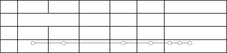
4-4 TACHYARRHYTHMIA THERAPY
VENTRICULAR THERAPY
• If the arrhythmia is not converted and an arrhythmia is redetected in
the same ventricular zone, the next programmed therapy in that zone
is selected and delivered (Figure 4-2 on page 4-4), followed again by
redetection. If the arrhythmia persists in the same zone, the therapy will
progress in that zone.
• If an arrhythmia crosses ventricular zones (accelerates or decelerates)
following therapy delivery and is redetected in a higher or lower ventricular
zone, a therapy of equal or greater strength than the previously delivered
therapy is selected from the detected zone and delivered (Figure 4-3 on
page 4-5 through Figure 4-10 on page 4-8). For shock therapy, the pulse
generator determines which shock to deliver prior to capacitor charging
based on the detected rate threshold. If during capacitor charging, the
tachyarrhythmia accelerates or decelerates from the initial detected rate,
the predetermined energy will still be delivered.
Redetection is performed after each therapy delivery to determine if further
therapy is required.
1 3 2 4 5 6 7
Zone ATP1 ATP2 QUICK
CONVERT ATP
Shock 1 Shock 2 Remaining Shocks
VF
VT
VT-1
On/Off
N/A
N/A
5 J
3 J
0.1 J
11 J
9 J
2 J
Burst Scan
Ramp Burst
max max max max max max
max max max max
max max max
Figure 4-2. Therapy delivery progression, arrhythmia remains in same zone as initially detected
After each redetection cycle, therapy delivery progresses in the direction
indicated by the circled numbers (Figure 4-3 on page 4-5 through Figure 4-10
on page 4-8).
• Upward sloping lines indicate acceleration of the arrhythmia to a higher
ventricular zone
• Downward sloping lines indicate deceleration into a lower ventricular zone
The lowest strength therapy is in the ATP columns; the therapy strengths
increase as you move to the right in the table.
- DRAFT -
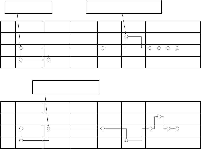
TACHYARRHYTHMIA THERAPY
VENTRICULAR THERAPY 4-5
NOTE: In the VT-1 zone of a 3-zone configuration or the VT zone of a
2-zone configuration, one or two ATP schemes may be programmed as the
only therapy, with all shocks in the lowest zone programmed to Off. If those
pacing schemes do not terminate an arrhythmia detected in the VT-1 zone, no
further therapy will be delivered in the episode unless the rate is redetected
in a higher zone.
1
3 6 7 8 9
4
5
2
Zone ATP1 ATP2 QUICK
CONVERT ATP
Shock 1 Shock 2 Remaining Shocks
VF
VT
VT-1
On/Off
N/A
N/A
2 J
3 J
0.1 J
11 J
9 J
2 J
Burst Off
Ramp Burst
max max max max max max
max max max max
max max max
When the rhythm accelerates to the VF zone, Shock
2 in the VF zone is delivered since Shock 1 is a lower
energy level than Shock 1 in the VT zone.
ATP1 in the VT zone is delivered
because it is considered of equal
strength to VT-1 ATP2 therapy.
Figure 4-3. Therapy delivery progression, ATP1 in the VT zone and shock 2 in the VF zone
3
1 8 9
5
4
2
6
7
Zone ATP1 ATP2 QUICK
CONVERT ATP
Shock 1 Shock 2 Remaining Shocks
VF
VT
VT-1
On/Off
N/A
N/A
11 J
5 J
3 J
17 J
9 J
5 J
Burst Scan
Ramp Burst
max max max max max max
max max max max
max max max
When the rhythm accelerates back to the VT
zone, ATP2 therapy is delivered because ATP1
has already been used during the episode.
Figure 4-4. Therapy delivery progression, ATP2 therapy
- DRAFT -
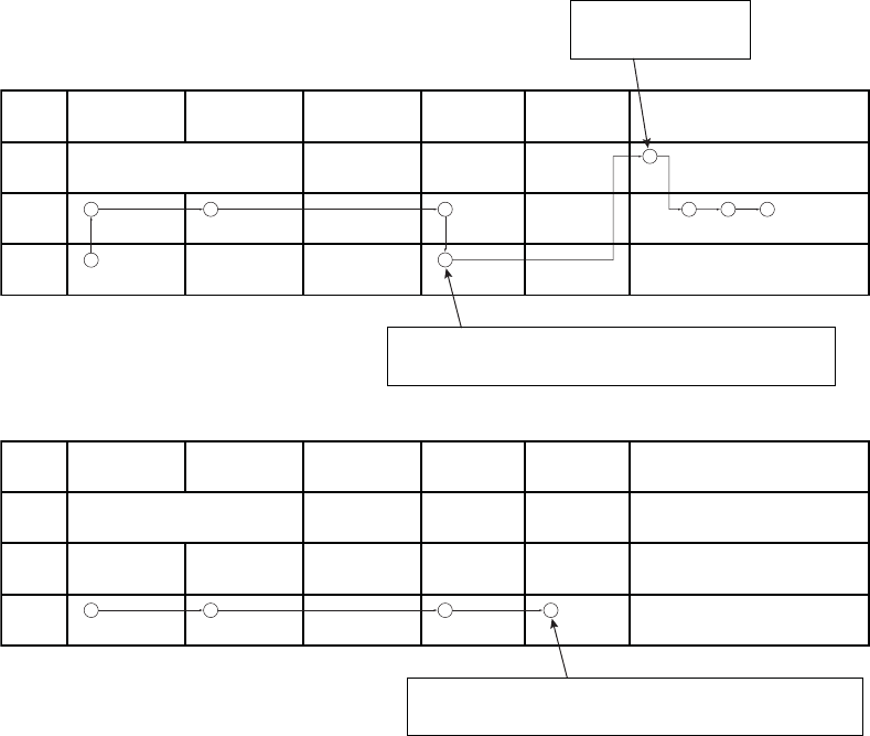
4-6 TACHYARRHYTHMIA THERAPY
VENTRICULAR THERAPY
3
5
2
1
4
6
8 9
7
Zone ATP1 ATP2 QUICK
CONVERT ATP
Shock 1 Shock 2 Remaining Shocks
VF
VT
VT-1
On/Off
N/A
N/A
5 J
1.1 J
3 J
11 J
9 J
5 J
Burst Scan
Ramp Burst
max max max max max max
max max max max
max max max
This is the third shock, since
two programmable shocks
have been delivered.
When the rhythm decelerates to the VT-1 zone, ATP2 of the VT-1 zone is
not delivered since a shock had already been delivered in the VT zone. So
the next higher strength therapy (Shock 1 of the VT-1 zone) is delivered.
Figure 4-5. Therapy delivery progression, shock 1 in the VT-1 zone
3
2
1 4
Zone ATP1 ATP2 QUICK
CONVERT ATP
Shock 1 Shock 2 Remaining Shocks
VF
VT
VT-1
On/Off
N/A
N/A
2 J
3 J
0.1 J
11 J
9 J
2 J
Burst Scan
Ramp Burst
max max max max max max
max max max max
Off Off Off
If the arrhythmia persists in the VT-1 zone after the second shock delivery,
no further shock therapy will be delivered unless the arrhythmia accelerates
to a higher zone since Shocks 3-5 are programmed Off in the VT-1 zone.
Figure 4-6. Therapy delivery progression, shocks 3 to 5 programmed to Off in the VT-1 zone
- DRAFT -
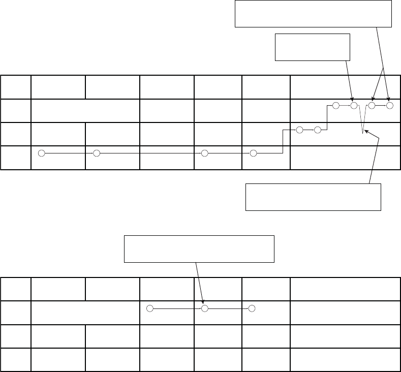
TACHYARRHYTHMIA THERAPY
VENTRICULAR THERAPY 4-7
5 6
7
3
2
1 4
10 8 9
The arrhythmia accelerated back to the VF zone, the
seventh shock is delivered. The arrhythmia persists in
the VF zone so the eighth (and final) shock is delivered.
A sixth shock is delivered
since the arrhythmia is in
the VF zone.
The arrhythmia decelerated to a lower zone, an
additional shock would not be delivered until the
arrhythmia accelerated back to the VF zone.
Zone ATP1 ATP2 QUICK
CONVERT ATP
Shock 1 Shock 2 Remaining Shocks
VF
VT
VT-1
On/Off
N/A
N/A
2 J
3 J
0.1 J
11 J
9 J
2 J
Burst Off
Ramp Burst
max max max max max max
max max max max
max max max
Figure 4-7. Therapy delivery progression, sixth shock delivered
1 3
2
Zone ATP1 ATP2
If reconfirmation indicates the arrhythmia persists
after delivery of QUICK CONVERT ATP, the device
immediately begins charging for Shock 1.
QUICK
CONVERT ATP
Shock 1 Shock 2 Remaining Shocks
VF
VT
VT-1
On
N/A
N/A
11 J
3 J
0.1 J
21 J
9 J
2 J
Burst Scan
Ramp Burst
max max max max max max
max max max max
max max max
Figure 4-8. Therapy delivery progression, QUICK CONVERT ATP and shock in the VF zone
- DRAFT -

4-8 TACHYARRHYTHMIA THERAPY
VENTRICULAR THERAPY
2
1
4 5
3
Zone ATP1 ATP2 QUICK
CONVERT ATP
Shock 1 Shock 2 Remaining Shocks
VF
VT
VT-1
On
N/A
N/A
2 J
3 J
0.1 J
11 J
9 J
2 J
Burst Scan
Ramp Burst
max max max max max max
max max max max
max max max
ATP1 in the VT zone is delivered because
it is considered of equal strength to QUICK
CONVERT ATP therapy.
Figure 4-9. Therapy delivery progression, QUICK CONVERT ATP decelerates the rhythm, ATP1 and shock
delivered in the VT zone
1
2 3
Zone ATP1 ATP2 QUICK
CONVERT ATP
Shock 1 Shock 2 Remaining Shocks
VF
VT
VT-1
On
N/A
N/A
11 J
3 J
0.1 J
21 J
9 J
2 J
Burst Scan
Ramp Burst
max max max max max max
max max max max
max max max
When the rhythm accelerates to the VF zone, Shock
1 is delivered because QUICK CONVERT ATP is
only available as the first therapy in an episode.
Figure 4-10. Therapy delivery progression, ATP1 in VT zone accelerates the rhythm, QUICK CONVERT ATP
isskippedinVFzone
Ventricular Redetection after Ventricular Therapy Delivery
After ventricular therapy delivery, the pulse generator uses redetection criteria
to evaluate the rhythm and determine whether more therapy is appropriate.
When redetection criteria are satisfied, the rules for therapy selection then
determine the type of therapy to deliver.
Ventricular Redetection after Ventricular ATP Therapy
Ventricular Redetection after ventricular ATP therapy determines if an
arrhythmia has been terminated.
As a ventricular ATP scheme is delivered, the pulse generator monitors the
cardiac rate after each burst and uses ventricular detection windows (looking
- DRAFT -
TACHYARRHYTHMIA THERAPY
VENTRICULAR THERAPY 4-9
for 8 of 10 fast intervals) and the Ventricular Redetection Duration to determine
ifthearrhythmiahasterminated.
The ATP scheme will continue with the next bursts in the sequence until any
one of the following conditions is satisfied:
• Redetection declares that the therapy has been successful (end-of-episode)
•Thespecified number of ATP bursts in the scheme has been delivered
• The ATP Time-out for the ventricular zone has expired
• The detected ventricular arrhythmia rate changes to a different ventricular
rate zone, whereby a different therapy is selected
• Shock If Unstable forces the device to skip the remaining ATP therapy
and initiate shock therapy
• A DIVERT THERAPY command is received from the PRM during delivery
of a burst of a scheme
• A magnet abort occurs during delivery of a scheme
• The temporary Tachy Mode has changed
• A commanded therapy is requested
• The episode ends due to reprogrammed Tachy Mode, reprogrammed
ventricular tachy parameters, or attempted induction method or lead test
NOTE: Aborting an ATP burst terminates the affected ATP scheme. If further
therapy is required, the next programmed therapy (either ATP or shocks) in
the prescription is initiated.
Ventricular Redetection after Ventricular Shock Therapy
Ventricular redetection after ventricular shock therapy determines if an
arrhythmia has been terminated.
As shock therapy is delivered, the pulse generator monitors the cardiac rate
after each shock and uses ventricular detection windows (looking for 8 of
10 fast intervals) and post-shock detection enhancements, if applicable, to
- DRAFT -
4-10 TACHYARRHYTHMIA THERAPY
ANTITACHYCARDIA PACING THERAPIES AND PARAMETERS
determine if the arrhythmia has been terminated. Shock therapy will continue
until one of the following conditions is satisfied:
• Redetection declares the therapy has been successful (end-of-episode)
• All available ventricular shocks have been delivered for an episode
• The rhythm is redetected in either the VT or VT-1 zone, the available
number of programmed shock(s) in those zones has been delivered and
the arrhythmia stays in one of these lower zones
If all available shocks have been delivered for an episode, no further therapy
is available until the pulse generator monitors a rate below the lowest rate
threshold for 30 seconds and end-of-episode is declared.
ANTITACHYCARDIA PACING THERAPIES AND PARAMETERS
Antitachycardia Pacing (ATP) therapy and parameters enable the pulse
generator to interrupt the following fast rhythms by delivering a series of
critically timed pacing pulses:
• Monomorphic ventricular tachycardia
• Supraventricular tachycardias
ATP Therapy is delivered when the last sensed event fulfills the programmed
detection criteria (Figure 4-11 on page 4-11).
An ATP scheme may be customized with the following parameters:
• Number of bursts delivered
• Number of pulses within each burst
• Coupling Interval
• Burst Cycle Length
• Minimum pacing interval
These parameters can be programmed to produce the following ATP therapy
schemes:
•Burst
•Ramp
•Scan
- DRAFT -
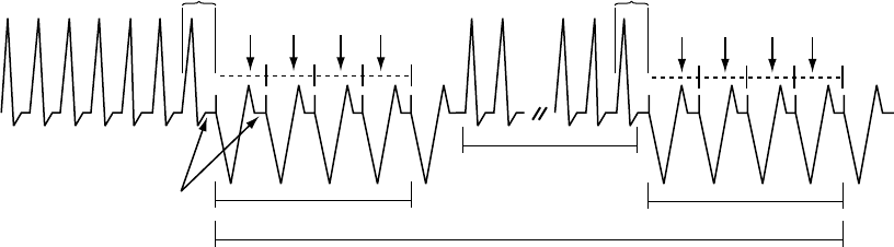
TACHYARRHYTHMIA THERAPY
ANTITACHYCARDIA PACING THERAPIES AND PARAMETERS 4-11
• Ramp/Scan
The ATP amplitude and pulse width are common to all schemes. They are
independently programmable from the normal pacing settings. The ATP
amplitude and pulse width share the same programmable value as the
post-therapy pacing settings.
Coupling
Interval
Coupling
Interval
Burst Cycle Length
Burst 1 Burst 2
ATP Scheme
Redetection
ATP Pace Pulse
Burst Cycle Length
Figure 4-11. ATP therapy basic parameters are Coupling Interval, Burst Cycle Length, Number of Bursts,
and Number of Pulses within each burst.
Burst Parameters
A burst is a series of critically timed pacing pulses delivered by the pulse
generator during ATP therapy. By programming burst parameters, you can
optimize ATP therapy for the patient.
All ATP schemes have several parameters in common. In addition to
programming the type of scheme (Off, Burst, Ramp, Scan, Ramp/Scan), the
following burst parameters are programmable (Figure 4-12 on page 4-12):
• The Number of Bursts parameter determines the number of bursts used
in an ATP scheme and may be programmed independently for each ATP
scheme. Programming the parameter to Off will deactivate the ATP
scheme.
• The Initial Pulse Count parameter determines the number of pulses
delivered in the first burst of a scheme.
• The Pulse Increment parameter determines the number of pulses per burst
to be increased for each successive burst in the scheme.
- DRAFT -
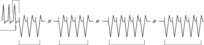
4-12 TACHYARRHYTHMIA THERAPY
ANTITACHYCARDIA PACING THERAPIES AND PARAMETERS
• The Maximum Number of Pulses parameter determines the greatest
number of pulses used in an ATP burst and may be programmed
independently for each ATP scheme. After the maximum number of pulses
is reached in a burst, each additional burst remaining in the scheme
contains the programmed Maximum Number of Pulses. The parameter is
available only if the Pulse Increment is greater than zero.
Coupling
Interval
Redetect Redetect Redetect
Detection
Satisfied
Burst 1; Initial
pulse count at 3
Burst 2; Pulse count
incremented by 1
Burst 3; Pulse count
incremented by 1;
Maximum Number of
Pulses reached
Burst 4; (programmed
number); Pulse count
remaining at Maximum
Number of Pulses (5)
Number of Bursts = 4
Initial Pulse Count = 3
Pulse Increment = 1
Maximum Number of Pulses = 5
Figure 4-12. Interaction of Maximum Number of Pulses and Number of Bursts
Coupling Interval and Coupling Interval Decrement
The Coupling Interval controls the timing of the firstpulseinaburst.Itdefines
thetimebetweenthelastsensedeventthatfulfills the detection criteria and
delivery of the first pulse in a burst.
The Coupling Interval is programmed independent from the Burst Cycle Length.
This allows aggressive ramps and scans to be used without compromising
capture of the first pacing pulse in a burst. The Coupling Interval can be
programmed as any of the following:
• Adaptive, with timing specified as percentages of the computed average
heart rate
•Afixed interval, with timing specified in absolute time (ms) independent of
the measured average rate
When programmed as adaptive, the Coupling Interval adjusts to the patient’s
rhythmbasedonafour-cycleaverage(Figure4-13onpage4-13). The
Coupling Interval Decrement may be programmed such that the Coupling
- DRAFT -
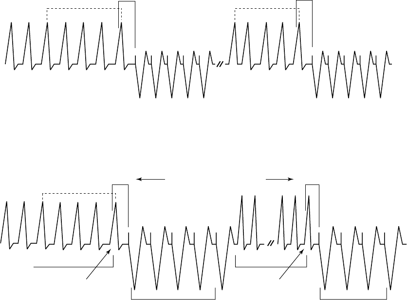
TACHYARRHYTHMIA THERAPY
ANTITACHYCARDIA PACING THERAPIES AND PARAMETERS 4-13
Interval decreases from one burst to the next within a multiple-burst scheme
(Figure4-14onpage4-13).
NOTE: You cannot program an ATP burst that lasts longer than 15 seconds.
The length of an adaptive burst is calculated based on the interval of the
ventricular zone in which the ATP is programmed, which means it is based
on worst-case timing.
Coupling Interval = 382 ms
4-Cycle Average = 420 ms
400
ms
410
ms
420
ms
450
ms
Coupling Interval (C.I.) = 91%
First C.I. is 420 x 91% = 382 ms
Second C.I. is 400 x 91% = 364 ms
The 4-cycle average is calculated on the four cycles prior to each tachycardia therapy delivery
only when no Decrement (Coupling Interval or Scan) is programmed.
Coupling Interval = 364 ms
4-Cycle Average = 400 ms
Figure 4-13. Adaptive Coupling Interval, Coupling Interval Decrement and Scan Decrement programmed to 0
Coupling Interval = 91%
C.I. Decrement = 10 ms
4-Cycle Average = 420 ms
Coupling
Interval =
382 ms Coupling Interval Decrement
(4-cycle average is not recalculated)
Coupling
Interval =
372 ms
Paced Pulses
Last sensed
R-wave that fulfills
redetection
Redetection
satisfied
Paced Pulses
Last sensed
R-wave that fulfills
detection
Detection satisfied
400
ms
410
ms
420
ms
450
ms
Figure 4-14. Coupling Interval Decrement
The following information should be taken into consideration when programming
the Coupling Interval and Coupling Interval Decrement:
• When the Coupling Interval Decrement is programmed to On, the
programmedATPschemeiscalledaScan
- DRAFT -
4-14 TACHYARRHYTHMIA THERAPY
ANTITACHYCARDIA PACING THERAPIES AND PARAMETERS
• When the Coupling Interval is programmed as adaptive, the Coupling
Interval will not re-adapt following redetection when the following are
programmed to On (greater than zero):
– Coupling Interval Decrement––the decrement value determines the
timing of the first pulse in subsequent bursts
– Scan Decrement––the decrement value determines the timing of the
second pulse in subsequent bursts
Burst Cycle Length (BCL)
The Burst Cycle Length controls the interval between pacing pulses after the
Coupling Interval.
This timing is controlled in the same fashion as the Coupling Interval: rate
adaptive to the sensed tachycardia or fixedtimespecified in ms.
NOTE: An adaptive BCL is affected in the same manner as an adaptive
Coupling Interval; the average cycle length is not continually recalculated for
subsequent bursts if the Scan Decrement or Coupling Interval Decrement are
programmed to On.
The following parameters may be programmed to decrement the burst cycle
length during an ATP scheme:
• Ramp Decrement controls the pulse timing within a given burst
• Scan Decrement controls the pulse timing between bursts
Minimum Interval
The Minimum Interval limits the Coupling Interval and the BCL in Burst, Ramp,
and Scan.
If the Coupling Interval reaches the limit, subsequent Coupling Intervals
will remain at the minimum value. Likewise, if the BCL reaches the limit,
subsequent BCLs will remain at the minimum value. The Coupling Interval and
BCL may reach the limit independently.
- DRAFT -
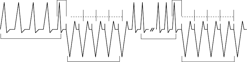
TACHYARRHYTHMIA THERAPY
ANTITACHYCARDIA PACING THERAPIES AND PARAMETERS 4-15
Burst Scheme
A Burst scheme is a sequence of critically timed pacing pulses intended to
interrupt a reentrant loop, usually delivered at a rate faster than the patient’s
tachycardia.
An ATP scheme is defined as a Burst (as indicated on the PRM screen) when
the timing of all pacing intervals within a burst is the same. The first BCL of
each Burst is determined by the programmed BCL. When the number of pulses
programmed in a Burst is greater than one, you can use the BCL to control the
timing between these paced pulses (Figure 4-15 on page 4-15).
Coupling
Interval
400
ms
410
ms
420
ms
450
ms
315
ms
BCL
315
ms
BCL
315
ms
BCL
315
ms
BCL
Coupling
Interval
300
ms
BCL
300
ms
BCL
300
ms
BCL
300
ms
BCL
Burst
4-Cycle Average = 400 ms
Burst
4-Cycle Average = 420 ms
BCL = 75%
420 ms x .75 = 315 ms
400 ms x .75 = 300 ms
The first BCL of each burst is calculated by multiplying the 4-cycle average prior to
delivery of the first pacing pulse of the burst by the BCL percentage.
Figure 4-15. Adaptive-rate Burst scheme
Ramp Scheme
A Ramp scheme is a burst in which each paced-to-paced interval within the
burst is shortened (decremented).
To program a Ramp scheme, program (in ms) the Ramp Decrement to specify
how much the paced-to-paced interval should be shortened, and the Scan
Decrement and Coupling Interval Decrement each to 0 ms. As each additional
paced pulse in a burst is delivered, its interval is shortened by the programmed
Ramp Decrement until either of the following occur:
• The last paced pulse of the burst is delivered
• The Minimum Interval is reached
- DRAFT -
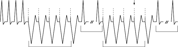
4-16 TACHYARRHYTHMIA THERAPY
ANTITACHYCARDIA PACING THERAPIES AND PARAMETERS
If subsequent bursts are required, the programmed Ramp Decrement will be
applied based on the calculated BCL of that subsequent burst (Figure 4-16 on
page 4-16).
Burst Cycle Length = 75%
Ramp Decrement (R-R Within Burst) = 10 ms
Scan Decrement (R-R Between Bursts) = 0 ms
C.I. Decrement = 0 ms
Minimum Interval = 265 ms
300
ms
290
ms
280
ms
270
ms
4-Cycle Average
= 400 ms
Ramp Ramp
4-Cycle Average
= 380 ms
Readapt 75%
285
ms
275
ms
265
ms
265
ms
Minimum interval reached;
subsequent interval is not
decremented.
Redetect
Figure 4-16. Adaptive Ramp Scheme, Coupling Interval Decrement and Scan Decrement programmed to 0
Scan Scheme
A Scan scheme is a burst in which the BCL of each burst in a scheme is
systematically shortened (decremented) between successive bursts.
YoucanprogramaScanschemebyprogrammingtheScanDecrementto
specify the BCL decrement to a value greater than 0 ms, while the Ramp
Decrement is programmed to 0 ms. The BCL of subsequent bursts is
determined by subtracting the Scan Decrement from the BCL of the previous
burst (Figure 4-17 on page 4-17).
- DRAFT -
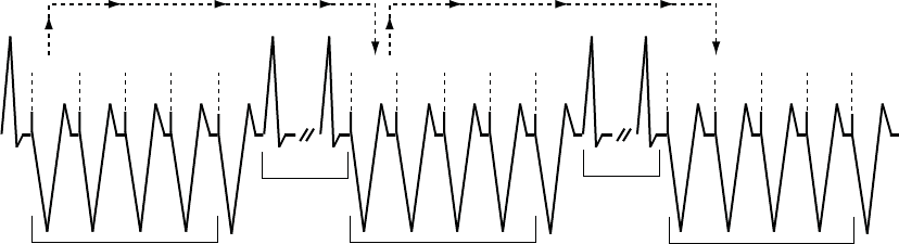
TACHYARRHYTHMIA THERAPY
ANTITACHYCARDIA PACING THERAPIES AND PARAMETERS 4-17
Initial BCL is determined and then Scan
Decrement is applied on the next burst
BCL of previous Burst is determined and then Scan
Decrement is applied again on the next burst
300
ms
300
ms
300
ms
300
ms
290
ms
290
ms
290
ms
290
ms
280
ms
280
ms
280
ms
280
ms
Burst Cycle Length = 300 ms
Scan Decrement = 10 ms
Ramp Decrement = 0 ms
Coupling Interval Decrement = 0 ms
Scan Scan
Redetect Redetect
Scan
Figure 4-17. Scan scheme, nonadaptive BCL and Scan Decrement programmed on
Ramp/Scan Scheme
A Ramp/Scan scheme is a sequence of bursts. Each scheme contains a Ramp
Decrement and a Scan Decrement (Figure 4-18 on page 4-18).
- DRAFT -
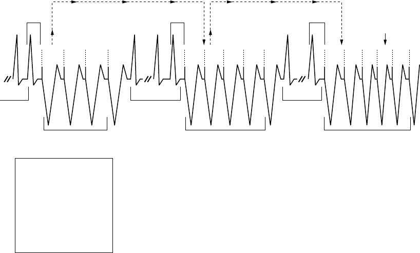
4-18 TACHYARRHYTHMIA THERAPY
ANTITACHYCARDIA PACING THERAPIES AND PARAMETERS
290
ms
270
ms
280
ms
270
ms*
240
ms
250
ms
260
ms
240
ms
250
ms
220
ms
220
ms
230
ms
Minimum
interval
reached
4-Cycle
A
verage
= 370 ms
PARAMETER
Number of Bursts
Pulses per Burst:
Initial
Increment
Maximum
Coupling Interval
Decrement
Burst Cycle Length
Ramp Decrement
Scan Decrement
Minimum Interval
VALUE
3
4
1
6
81%
0 ms
78%
10 ms
20 ms
220 ms
* When a Scan Decrement is programmed to On, the Coupling Interval and
BCL, if programmed as a percentage, will not re-adapt following redetection.
Maximum Number of Pulses
reached (6) and Maximum
Number of Bursts reached (3)
Number of Pulses
incremented by 1
Ramp Burst Ramp/Scan Burst Ramp/Scan Burst
Redetect Redetect
C.I. 300 ms
Scan Scan
C.I. 300 ms* C.I. 300 ms*
Figure 4-18. Ramp/Scan scheme, interaction of ATP parameters
To program a Ramp/Scan scheme, both the Scan Decrement and Ramp
Decrement are programmed to values greater than 0 ms.
ATP Pulse Width and ATP Amplitude
The ATP Pulse Width is the duration of a pacing pulse. The ATP Amplitude is
the leading edge voltage of a pacing pulse.
The ATP Pulse Width and ATP Amplitude parameters share the same value
as the post therapy pacing Pulse Width and Amplitude. If the programmable
value is changed for one parameter, that value will be reflected in the other
parameters.
TheprogrammedATPPulseWidthandATPAmplitudearesharedforallATP
schemes regardless of zone and position in a prescription. The ATP amplitude
and pulse width share the same programmable value as the post-therapy
pacing settings.
- DRAFT -
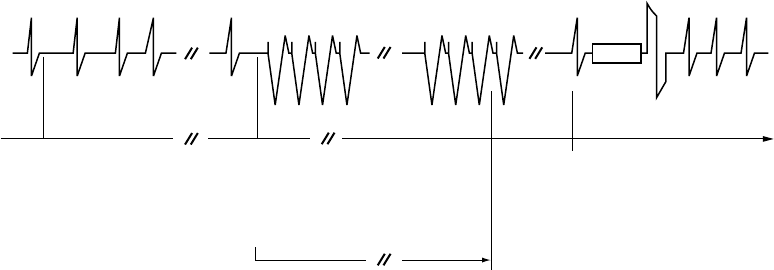
TACHYARRHYTHMIA THERAPY
ANTITACHYCARDIA PACING THERAPIES AND PARAMETERS 4-19
Ventricular ATP Time-out
The Ventricular ATP Time-out forces the pulse generator to skip over any
remaining ATP therapy in a ventricular zone to begin delivering ventricular
shock therapy programmed in the same zone. This parameter is effective
only for ventricular therapy delivery.
The ATP Time-out may be used in the VT or VT-1 zone as long as ATP therapy
is programmed to On. Timer values are independent, although VT-1 ATP
Time-out must be equal to or greater than the VT ATP Time-out.
The timer starts when the first burst is delivered and continues until any of the
following occur:
• The timer expires (Figure 4-19 on page 4-19)
• A ventricular shock is delivered
• The ventricular episode ends
The time-out is examined after each redetection sequence to determine if
further ATP bursts can be delivered. If the time-out has been reached or
exceeded, further ATP therapy will not be initiated during that ventricular
episode. The time-out will not terminate a burst in process.
Detection window met.
Start episode.
Start Duration.
Start stability analysis.
Duration expires.
Initiate ATP therapy.
Start ATP Time-out.
Redetection Duration expires.
Initiate shock therapy.
Charge
Redetect Redetect
ATP Time-out expires
30 s
Figure 4-19. ATP Time-out expiration
NOTE: Once a ventricular shock has been delivered during a ventricular
episode, ATP will no longer be invoked, irrespective of the time remaining
on the ATP Time-out timer.
- DRAFT -
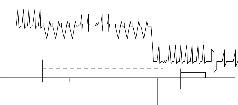
4-20 TACHYARRHYTHMIA THERAPY
ANTITACHYCARDIA PACING THERAPIES AND PARAMETERS
The timer alone does not invoke therapy; the rate and duration criteria and
detection enhancements must still be satisfied in order for a shock therapy
to be delivered.
If three zones are programmed, you may program ATP Time-out settings in
each of the lower two ventricular zones (Figure 4-20 on page 4-20).
0 s 10 s 20 s 30 s 40 s
VF Zone
VT Zone
VT-1 Zone
VT Detection
window satisfied.
Duration starts.
Start episode. VT Detection met.
Therapy intitiated.
Start ATP Time-out.
AT Time-out expires
in VT zone.
VT-1
Time-out
expires.
VT-1 Detection met.
Initiate shock therapy.
Programmed therapy for lower zones:
VT-1 ATP Time-out = 40 s
VT ATP Time-out = 30 s
ATP is programmed in VT-1 and VT zones.
Redetection and
ATP bursts
ATP Time-out
ATP 1 ATP 1
Burst 1 Burst 5
Redetect
Charging
Rhythm changes to VT-1 zone
Figure 4-20. ATP Time-outs, 3-zone configuration
QUICK CONVERT ATP
QUICK CONVERT ATP provides you with an additional option to treat fast,
monomorphic VT that is detected in the VF zone.
When QUICK CONVERT ATP is programmed to On, the pulse generator
delivers one burst of ATP for an episode detected in the VF zone in an
attempt to avoid an otherwise scheduled charge and painful shock for a
pace-terminable fast VT.
When delivering QUICK CONVERT ATP therapy, the pulse generator delivers
one burst of ATP for an episode detected in the VF zone. This therapy consists
of 8 pacing pulses at 88% Coupling Interval and 88% BCL. It is delivered only
as the first therapy attempted in an episode and is followed by reconfirmation
(2 out of 3 intervals faster than the lowest rate threshold) prior to the shock
sequence.
- DRAFT -
TACHYARRHYTHMIA THERAPY
VENTRICULAR SHOCK THERAPY AND PARAMETERS 4-21
In the event that QUICK CONVERT ATP was unsuccessful in converting the
rhythm and shock therapy is required, the feature’s algorithm minimizes the
delay to begin charging. QUICK CONVERT ATP is not applied to any rhythm
above a maximum rate of 250 bpm.
VENTRICULAR SHOCK THERAPY AND PARAMETERS
The pulse generator delivers shocks synchronous to a sensed event. The
shock vector, energy level, and polarity of the shocks are programmable.
Ventricular Shock Vector
The programmed Ventricular Shock Vector indicates the vector of energy
delivery for ventricular shock therapy.
The following programmable configurations are available:
• RV Coil to RA Coil and Can––this vector is also known as the V-TRIAD
vector. It uses the metallic housing of the pulse generator as an active
electrode (“hot can”) combined with the ENDOTAK two-electrode
defibrillation lead. Energy is sent via a dual-current pathway from the distal
shocking electrode to the proximal electrode and to the pulse generator
case.
• RV Coil to Can––this vector uses the metallic housing of the pulse
generator as an active electrode (“hot can”). Energy is sent from the distal
shocking electrode to the pulse generator case. This configuration should
be selected when using a single-coil lead.
• RV Coil to RA Coil––this vector removes the pulse generator case as
an active electrode and is also known as a “cold can” vector. Energy is
sent from the distal shocking electrode to the proximal electrode. This
vector should never be used with a single-coil lead, as a shock will not
be delivered.
Ventricular Shock Energy
Ventricular shock energy determines the strength of shock therapy delivered
by the pulse generator.
Shock output remains constant over the lifetime of the pulse generator,
regardless of changes in lead impedance or battery voltage. The constant
- DRAFT -

4-22 TACHYARRHYTHMIA THERAPY
VENTRICULAR SHOCK THERAPY AND PARAMETERS
output is accomplished by varying pulse width to adjust to changes in lead
impedance.
The first two shocks in each ventricular zone can be programmed to optimize
charge time, longevity, and safety margins. The remaining shock energies in
each zone are nonprogrammable at the maximum-energy value.
Charge Time
Charge time is the time the pulse generator requires to charge for delivery of
the programmed shock energy.
Charge time is dependent on the following:
• Programmed output energy level
• Battery condition
• Condition of the energy storage capacitors
Charge times increase as the pulse generator is programmed to higher energy
output levels and as the battery depletes (Table 4-1 on page 4-22).
Capacitor deformation can occur during inactive periods and may result in a
slightly longer charge time. To reduce the impact of capacitor deformation on
charge time, the capacitors are automatically reformed.
Table 4-1. Typical charge time required at 37 degrees C at BOL
Energy Stored (J)aEnergy Delivered
(J)b
Charge Time
(seconds)c
11.0 10.0 1.9
17.0 15.0 2.9
26.0 22.0 4.7
41.0d35.0 8.4
a. Values indicate the energy level stored on the capacitors and correspond to the value programmed for shock energy parameters.
b. The energy delivered indicates the shock energy level delivered through the shocking electrodes.
c. Charge times shown are at BOL after capacitor re-formation.
d. HE.
Waveform Polarity
Waveform polarity reflects the relationship between the leading edge voltages
on the defibrillating output electrodes. All shocks will be delivered using a
biphasic waveform (Figure 4-21 on page 4-23).
- DRAFT -
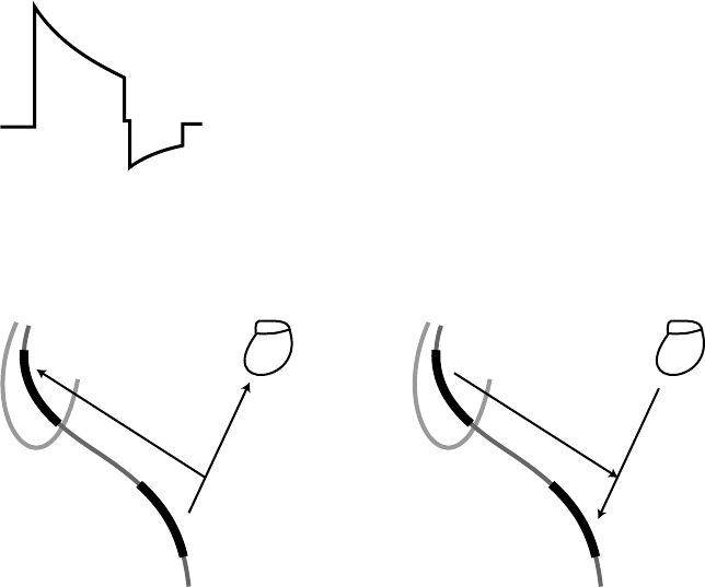
TACHYARRHYTHMIA THERAPY
VENTRICULAR SHOCK THERAPY AND PARAMETERS 4-23
The selection of the shock polarity applies to all shocks delivered by the device.
If the preceding shocks in a zone are unsuccessful, the last shock of that zone
will be automatically delivered at an inverted polarity to the previous shock
(initial or reversed) (Figure 4-22 on page 4-23).
CAUTION: For IS-1/DF-1 leads, never change the shock waveform
polarity by physically switching the lead anodes and cathodes in the pulse
generator header—use the programmable Polarity feature. Device damage
or nonconversion of the arrhythmia post-operatively may result if the polarity
is switched physically.
Biphasic
V1
V2
PW1 PW2
V3
V4
PW = Pulse Width
PW2 = PW1 x 0.66
V2 = V3
Figure 4-21. Biphasic waveform
+
–
+
–
+
–
Initial polarity Reverse polarity
Figure 4-22. Polarity of shock delivery
Committed Shock/Reconfirmation of the Ventricular Arrhythmia
Committed Shock/Reconfirmation refers to the monitoring performed by the
pulse generator before delivery of a ventricular shock.
- DRAFT -
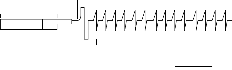
4-24 TACHYARRHYTHMIA THERAPY
VENTRICULAR SHOCK THERAPY AND PARAMETERS
If the patient is subject to non-sustained arrhythmias, reconfirmation may be
desirable in order to prevent delivery of unnecessary shocks to the patient.
The device monitors tachyarrhythmias during and immediately following
capacitor charging. During this time, it checks for the spontaneous conversion
of the tachyarrhythmia and determines whether ventricular shock therapy
should be delivered; it does not affect therapy selection.
Ventricular shock therapy can be programmed as committed or non-committed.
If the Committed Shock feature is programmed to On, the shock is delivered
synchronously with the first sensed R-wave following a 500-ms delay after the
capacitors are charged, whether the arrhythmia is sustained or not (Figure 4-23
on page 4-24). The 500-ms delay allows a minimum time for a divert command
to be issued from the PRM, if desired. If there is no sensed R-wave detected
within 2 seconds following the end of charging, the ventricular shock is
delivered asynchronously at the end of the 2-second interval.
Shock
2 3 4 5 6 7 8 9 10 11 121
FF FF F F FFF F
Shock is committed.
Synchronize with R-wave and deliver shock.
Duration complete.
Start charging.
Refractory
period
Divert window
Charging 500 ms
135 ms
Redetection starts. Detection window satisfied.
Post-Shock Duration starts.
Number of intervals
(F = Fast)
Figure 4-23. Committed Shock is programmed to On, Reconfirmation is Off
NOTE: There is a forced 135-ms refractory period following the end of
charging; events that occur during the first 135 ms of the 500-ms delay are
ignored.
If the Committed Shock feature is programmed to Off, Reconfirmation consists
of the following steps:
1. During capacitor charging, the pulse generator continues to sense the
arrhythmia. Sensed and paced beats are evaluated. If 5 slow beats (sensed
or paced) are counted in a 10-beat detection window (or 4 consecutive
slow beats after an unsuccessful QUICK CONVERT ATP attempt), the
pulse generator stops charging and considers this a Diverted-Reconfirm.
- DRAFT -
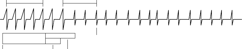
TACHYARRHYTHMIA THERAPY
VENTRICULAR SHOCK THERAPY AND PARAMETERS 4-25
2. If 5 of 10 beats are not detected as slow (or less than 4 consecutive slow
beats after an unsuccessful QUICK CONVERT ATP attempt) and charging
completes, post-charge reconfirmation is performed after charging ends.
After the post-charge refractory and the first sensed event, the pulse
generator measures up to 3 intervals following charging and compares
them to the lowest rate threshold.
• If 2 of the 3 intervals following charging are faster than the lowest rate
threshold, the shock will be delivered synchronously with the second
fast event.
• If 2 of the 3 intervals following charging are slower than the lowest
rate threshold, the shock will not be delivered. If no beats are sensed,
pacing will begin at the programmed LRL following the 2-second
no-sense period. If a shock is not delivered, or if pacing pulses are
delivered, this is also considered a Diverted-Reconfirm.
If a shock is required after redetection, the charge time for the shock may
be short.
The reconfirmation algorithm will not allow two consecutive Diverted-Reconfirm
cycles. If the arrhythmia is detected after a Diverted-Reconfirm, the next shock
in the episode is delivered as if Committed Shock were programmed to On.
Once a shock has been delivered, the reconfirmation algorithm can be applied
again (Figure 4-24 on page 4-25).
23 4 56 7 81
23 4 51231
Intervals are measured and compared to the lowest Rate threshold. If 2 of 3 are slow,
the shock will not be delivered. If 2 of 3 are fast, the shock will be delivered.
Reconfirmation determines arrhythmia
is no longer present. Shock is not
delivered. If no beats are sensed,
pacing will start.
Duration complete.
Start charging.
Refractory
period
Divert
window
Intervals are measured
during charging.
Charging 500 ms
135 ms
Figure 4-24. Committed Shock is programmed to Off, reconfirmation is On
- DRAFT -
4-26 TACHYARRHYTHMIA THERAPY
VENTRICULAR SHOCK THERAPY AND PARAMETERS
- DRAFT -
- DRAFT -

Boston Scientific
4100 Hamline Avenue North
St. Paul, MN 55112–5798 USA
www.bostonscientific.com
1.800.CARDIAC (227.3422)
+1.651.582.4000
© 2007 Boston Scientificoritsaffiliates
All rights reserved.
357389-001 EN US 12/07
FCC ID: ESCCRMN11906
IC: 4794A-CRMN1196
Part 1 of 2
*357389-001*
- DRAFT -

SYSTEM GUIDE
TELIGEN™100
IMPLANTABLE CARDIOVERTER HIGH ENERGY
DEFIBRILLATOR
REF E102, E110
CAUTION: Federal law
restricts this device to sale by
or on the order of a physician
trained or experienced in
device implant and follow-up
procedures. Part 2 of 2
- DRAFT -
- DRAFT -

5-1
PACING THERAPIES
CHAPTER 5
This chapter contains the following topics:
• "Pacing Therapies" on page 5-2
• "Basic Parameters" on page 5-2
• "Post-Therapy Pacing" on page 5-9
• "Temporary Pacing" on page 5-10
• "Sensors and Trending" on page 5-11
• "Atrial Tachy Response" on page 5-19
• "Rate Enhancements" on page 5-26
• "Lead Configuration" on page 5-31
• "AV Delay" on page 5-32
• "Refractory" on page 5-36
• "Noise Response" on page 5-41
• "Ventricular Tachy Sensing Interactions" on page 5-43
- DRAFT -
5-2 PACING THERAPIES
PACING THERAPIES
PACING THERAPIES
Single chamber ICDs provide ventricular bipolar (pace/sense) normal and
post-therapy bradycardia pacing, including adaptive-rate modes. Dual chamber
ICDs provide both atrial and ventricular bipolar (pace/sense) normal and
post-therapy bradycardia pacing, including adaptive-rate modes.
The bradycardia pacing function is independent of the tachycardia detection
and therapy functions of the device, with the exception of interval-to-interval
sensing.
The pulse generator provides the following types of therapies:
Normal Bradycardia Pacing
• If the intrinsic heart rate falls below the programmed pacing rate (i.e., LRL),
the device delivers pacing pulses at the programmed settings
• Sensor-based rate modulation allows the pulse generator to adapt the
pacing rate to the patient’s changing activity levels
Post-Therapy Pacing—alternative bradycardia pacing therapy may be
delivered for a programmed period to ensure capture after delivery of a shock.
Additional Options
•Temporary Bradycardia Pacing––allows the clinician to examine
alternate therapies while maintaining the previously programmed Normal
pacing settings in the pulse generator memory.
•STAT PACE––initiates emergency ventricular pacing at high output settings
when commanded via the PRM using telemetry communication.
BASIC PARAMETERS
Normal Settings include the following:
• Pacing parameters, which are independently programmable from
post-therapy and temporary pacing parameters
• Pacing and Sensing
• Leads
• Sensors and Trending
- DRAFT -
PACING THERAPIES
BASIC PARAMETERS 5-3
Post-Therapy Settings include the following:
• Pacing parameters, which are independently programmable from normal
and temporary pacing parameters
• Post-ventricular shock
Brady Mode
Brady modes provide you with programmable options to help individualize
patient therapy.
This pulse generator includes the pacing modes identified in the Programmable
Options appendix.
Dual-Chamber Modes
Do not use DDD(R) and VDD(R) modes in the following situations:
• In patients with chronic refractory atrial tachyarrhythmias (atrial fibrillation
or flutter), which may trigger ventricular pacing
• In the presence of slow retrograde conduction that induces PMT, which
cannot be controlled by reprogramming selective parameter values
Atrial Pacing Modes
In DDD(R), DDI(R), and AAI(R) modes, atrial pacing may be ineffective in
the presence of chronic atrial fibrillation or flutter or in an atrium that does
not respond to electrical stimulation. In addition, the presence of clinically
significant conduction disturbances may contraindicate the use of atrial pacing.
WARNING: Do not use atrial tracking modes in patients with chronic refractory
atrial tachyarrhythmias. Tracking of atrial arrhythmias could result in VT or VF.
NOTE: If a separate pacemaker is desired, a dedicated bipolar pacemaker
is recommended.
NOTE: Refer to "Use of Atrial Information" on page 3-5 for additional
information about device performance when the atrial lead is programmed to
Off.
- DRAFT -
5-4 PACING THERAPIES
BASIC PARAMETERS
If you have any questions regarding the individualization of patient therapy,
contact your sales representative or call Technical Services at the number
shown on the back cover of this manual.
Lower Rate Limit (LRL)
LRL is the number of pulses per minute at which the pulse generator paces in
the absence of sensed intrinsic activity.
The following interactive limits are effective when programming the LRL.
Exercise caution when programming permanent pacing rates below 50 ppm or
above 100 ppm.
•LRLmustbelessthan:
–MPR
–MSR
– MTR (dual-chamber)
• LRL must be at least 15 ppm less than the lowest tachy zone threshold
• The greater of the following values must be at least 10 ppm less than the
lowest tachy zone threshold:
–MPR
–MSR
– MTR (dual-chamber)
Runaway Protection
Runaway protection is designed to prevent pacing rate accelerations for most
single-component failures. This feature is not programmable and operates
independently from the pulse generator’s main pacing circuitry.
The basic pulse period is equal to the pacing rate and the pulse interval (without
hysteresis). Runaway protection prevents the pacing rate from increasing
above 205 ppm.
NOTE: Magnet application does not affect the pacing rate (pulse interval).
NOTE: Runaway protection is not an absolute assurance that runaways will
not occur.
- DRAFT -
PACING THERAPIES
BASIC PARAMETERS 5-5
During PES, Manual Burst pacing, and ATP, runaway protection is temporarily
suspended to allow for high-rate pacing.
Maximum Tracking Rate (MTR)
TheMTRisthemaximumrateatwhichthepacedventricularratetracks1:1
with nonrefractory sensed atrial events. MTR applies to atrial synchronous
pacing modes, namely DDD(R) and VDD(R).
The following are considerations for programming the MTR:
• Interactive limits ("Lower Rate Limit (LRL)" on page 5-4).
• When the sensed atrial rate is between the programmed LRL and MTR, 1:1
ventricular pacing will occur in the absence of a sensed ventricular event
within the programmed AV Delay. If the sensed atrial rate exceeds the MTR,
the pulse generator might begin a Wenckebach-like behavior to prevent
the paced ventricular rate from exceeding the MTR. This Wenckebach-like
behavior is characterized by a progressive lengthening of the AV delay
until an occasional P-wave is not tracked because it falls into the PVARP.
This results in an occasional loss of 1:1 tracking as the pulse generator
synchronizes its paced ventricular rate to the next sensed P-wave. Should
the sensed atrial rate continue to increase further above the MTR, the ratio
of sensed atrial events to sequentially paced ventricular events becomes
lower until, eventually, 2:1 block results (e.g., 5:4, 4:3, 3:2, and finally 2:1).
• The PRM will not allow you to program an MTR interval shorter than TARP
(AV Delay + PVARP = TARP). If TARP is less than the interval of the
programmed MTR, then the pulse generator’s Wenckebach-like behavior
limits the ventricular pacing rate to the MTR. With TARP, the PRM does not
consider the AV Search AV Delay. If AV Search is on, Wenckebach-like
behavior may occur at rates lower than the MTR.
• Rapid changes in the paced ventricular rate (e.g., Wenckebach-like, 2:1
block) caused by sensed atrial rates above the MTR may be dampened or
eliminated by the implementation of any of the following:
–AFR
–ATR
– Rate Smoothing parameters and sensor input
–VRR
- DRAFT -
5-6 PACING THERAPIES
BASIC PARAMETERS
Maximum Sensor Rate (MSR)
MSR is the maximum pacing rate allowed as a result of sensor control from
accelerometer input.
The following considerations are important when programming MSR:
• Patient’s condition, age, and general health:
– Adaptive-rate pacing at higher rates may be inappropriate for patients
who experience angina or other symptoms of myocardial ischemia at
these higher rates
– An appropriate MSR should be selected based on an assessment of
the highest pacing rate that the patient can tolerate well
• Interactive limits ("Lower Rate Limit (LRL)" on page 5-4)
NOTE: If the pulse generator is operating in DDD(R) or VDD(R) mode, the
MSR and MTR may be programmed independently to different values.
MSR is independently programmable at, above, or below the MTR. If the MSR
settingishigherthantheMTR,apacingrateabovetheMTRmayoccurin
the presence of high activity levels.
Pacing above the MSR can only occur in response to sensed intrinsic atrial
activity.
With 1:1 conduction, the pulse generator maintains the A–A pacing rate by
extending the V–V pacing rate. This extension is determined by the degree of
difference between the AV Delay and the intrinsic ventricular conduction—often
referred to as modified atrial-based timing (Figure 5-1 on page 5-7).
- DRAFT -
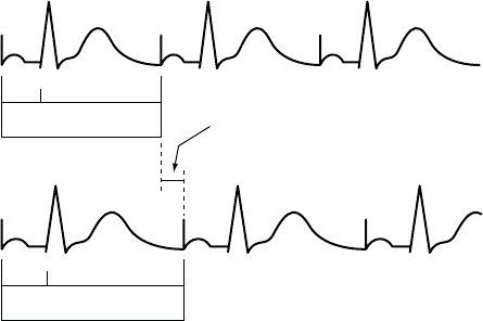
PACING THERAPIES
BASIC PARAMETERS 5-7
Pacing without modified
ventricular timing
Pacing with modified
ventricular timing
150 200 ms
AV VA
AV + VA Forced extension of
the V-A interval
150 200 ms
AV VA
AV + VA + extension
MSR 400 ms (150 min-1 [ppm])
AV 150 ms (conducted event)
V-A 200 ms
Pacing interval = AV + VA = 350 ms
MSR 400 ms (150 min-1 [ppm])
AV 150 ms
V-A Ext. 50 ms
VA 200 ms
Pacing interval = AV + VA + VA extension = 400 ms
The pulse generator’s timing algorithm provides effective pacing at the MSR with intrinsic ventricular conduction.
Extending the VA interval prevents the A pace from exceeding the MSR at high rates.
Figure 5-1. VA interval extension and MSR
Pulse Width
Pulse Width, also referred to as pulse duration, determines how long the output
pulse will be applied between the pacing electrodes.
The following considerations are important when programming Pulse Width:
• Pulse widths are independently programmable.
• The energy delivered to the heart is directly proportional to the pulse width.
Therefore, programming a shorter pulse width increases pulse generator
longevity. To prevent loss of capture, exercise caution when you are
programming permanent pulse width values of less than 0.3 ms (Figure 5-2
on page 5-8).
- DRAFT -
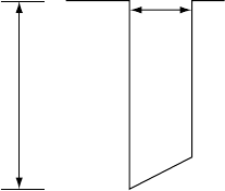
5-8 PACING THERAPIES
BASIC PARAMETERS
Pulse Width (ms)
Amplitude (V)
Figure 5-2. Pulse waveform
Amplitude
The pulse Amplitude, or voltage of the output pulse, is measured at the leading
edge of the output pulse (Figure 5-2 on page 5-8).
Amplitudes are independently programmable. The following considerations
are important:
• During temporary programming, the brady pacing mode may be
programmed to Off. In effect, this turns Amplitude off to monitor the
patient’s underlying rhythm.
• A minimum 2x voltage safety margin is recommended for each chamber
based on the capture thresholds, which should provide an adequate safety
margin and help preserve battery longevity.
• The energy delivered to the heart is directly proportional to the square
of the amplitude. In other words, doubling the amplitude quadruples
the energy delivered, which will decrease pulse generator longevity.
Programming to a lower Amplitude while maintaining an adequate safety
margin may increase battery longevity.
Sensitivity
The Sensitivity parameter allows the pulse generator to detect intrinsic cardiac
signals that exceed the programmed value.
All detection and timing decisions are based on the sensed cardiac cycle
length. These pulse generators use an automatic gain control circuit to
dynamically adjust the sensitivity.
- DRAFT -
PACING THERAPIES
POST-THERAPY PACING 5-9
• High Sensitivity (low value)—when Sensitivity is programmed to a very
sensitive setting, the pulse generator may detect signals unrelated to
cardiac depolarization (oversensing, such as sensing of myopotentials)
• Low Sensitivity (high value)—when Sensitivity is programmed to a
less sensitive setting, the pulse generator may not detect the cardiac
depolarization signal (undersensing)
POST-THERAPY PACING
Post-therapy pacing provides alternate pacing therapy following the delivery
of any shock.
The pacing mode and pacing therapies used following a shock are the same as
the programmed Normal pacing settings.
The following pacing parameters can be programmed independently from the
Normal pacing settings:
• Pacing Parameters—LRL, Amplitude, and Pulse Width
• Post Therapy Period
Post-Shock Pacing Delay
The Post-Shock Pacing Delay determines the earliest possible start of
post-shock pacing following the delivery of a ventricular shock and is fixed
at 3 seconds.
The timing of the initial pacing pulse in the Post-Therapy Period depends on
the cardiac activity during the Post-Shock Pacing Delay.
• If R-waves (and/or P-waves for dual-chamber pacing modes) are sensed
during the Post-Shock Pacing Delay, the device paces only when the
sensed rate is slower than the post-therapy LRL.
• If no R-waves (and/or P-waves for dual-chamber pacing modes) are
sensed during the Post-Shock Pacing Delay or if the interval since the
preceding P- or R-wave was greater than the escape interval, a pacing
pulse is delivered at the end of the Post-Shock Pacing Delay.
Subsequent pacing pulses are delivered as required, depending on the pacing
prescription.
- DRAFT -
5-10 PACING THERAPIES
TEMPORARY PACING
Post-Therapy Period
The Post-Therapy Period determines how long the pulse generator operates
using the post-therapy parameter values.
The Post-Therapy Period functions as follows:
• The period starts when the Post-Shock Pacing Delay expires
• On completion of this pacing period, the pulse generator reverts to the
programmed Normal pacing values
• While in process, the pacing period is not affected by the end of the current
episode
TEMPORARY PACING
The pulse generator can be programmed with temporary pacing parameter
values that differ from the programmed Normal Settings. This allows you
to examine alternate pacing therapies while maintaining the previously
programmed Normal Settings in the pulse generator memory. During the
Temporary function, all other bradycardia features are disabled.
NOTE: Post-therapy values are not affected.
To use this function, follow these steps:
1. From the Tests tab, select the Temp Brady tab to display the temporary
parameters. When the parameters are initially displayed, they are set to
the Normal Settings values ("Programmable Options" on page A-1).
NOTE: Post-therapy values are not shown even if post-therapy is presently
in effect.
2. Select the desired values; these values are independent from other pacing
functions.
3. Establish telemetry communication, then select the Start button. Pacing
begins at the temporary values. A dialog box indicates that temporary
parameters are being used, and a Stop button is provided.
NOTE: Temporary pacing cannot be started while a tachyarrhythmia episode
is in progress.
- DRAFT -
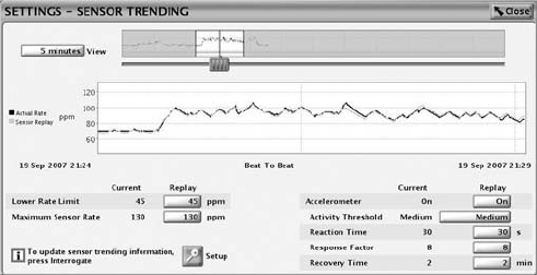
PACING THERAPIES
SENSORS AND TRENDING 5-11
NOTE: Emergency therapy is the only function that can be initiated until the
Temporary function is stopped.
4. To stop the Temporary pacing mode, select the Stop button. The Temporary
pacing mode also stops when you command emergency therapy from
the PRM or when you press the DIVERT THERAPY key. Once stopped,
the pacing reverts to the previously programmed Normal/Post-Therapy
settings.
SENSORS AND TRENDING
Sensor and trending therapies include the parameters as described.
Sensor Trending
Sensor Trending provides a graphical display of the sensor rate based on
sensor data. This feature evaluates the pulse generator’s rate response to the
patient’s detected activity level and provides useful information during exercise
testing.
The pulse generator collects and stores rate and sensor data. The rate data
represents the programmed parameters. The Sensor Replay option allows
you to adjust the parameter values and view the result without having to
repeat an exercise test. The pulse generator also collects and stores data in
nonadaptive-rate modes; however, without the sensor data comparison, only
rate data will be displayed.
The Sensor Trending screen is accessible from within Normal Settings
(Figure 5-3 on page 5-11).
Figure 5-3. Sensor Trending screen
Setup includes the following options:
- DRAFT -
5-12 PACING THERAPIES
SENSORS AND TRENDING
• Recording Method—programmable:
– 30-Second Average
– Beat to Beat
• Duration––programmable:
– When Recording Method is set to Off or 30-Second Average––fixed,
approximately 25 hours
– When Recording Method is set to Beat to Beat––fixed, approximately
40 minutes at 75 bpm
• Data Storage—programmable:
– Continuous—contains the most recent data available. Storage
starts when setup is confirmed and continuously records the latest
information, overwriting the oldest data until the information is
retrieved. This option allows you to view data for the recording duration
immediately prior to data retrieval.
– Fixed—storage starts when setup is confirmed and continues until
device memory storage is full. This allows you to view data from initial
setup for a fixedamountoftime.
– Off—when Sensor Trending is programmed to Off, no trending data
is gathered.
Select the View button to vary the time period for how much data is visible;
options exist for 1–25 hours. To adjust the vertical axis, move the slider bar
at the bottom of the display window.
Adaptive-rate Pacing
In adaptive-rate pacing modes, sensors are used to detect changes in
the patient’s metabolic demand and increase the pacing rate accordingly.
Adaptive-rate pacing is intended for patients who exhibit chronotropic
incompetence and who would benefit from increased pacing rates that are
concurrent with physical activity.
When adaptive-rate parameters are programmed, the pacing rate increases
in response to increased activity, then decreases as the activity returns to a
resting level.
- DRAFT -
PACING THERAPIES
SENSORS AND TRENDING 5-13
NOTE: Activity involving minimal upper body motion, such as bicycling, may
result in only a moderate pacing response.
NOTE: Adaptive-rate pacing has been shown to be potentially proarrhythmic.
Use caution when programming adaptive-rate features.
Accelerometer
The accelerometer detects motion that is associated with a patient’s physical
activity and generates an electronic signal that is proportional to the amount
of body motion. Based on accelerometer input, the pulse generator estimates
the patient’s energy expenditure as a result of exercise, then translates it into
a rate increase.
The pulse generator senses body motion by means of an integrated circuit
accelerometer located on the hybrid circuit. The accelerometer sensor
responds to activity in the frequency range of typical physiologic activity (1–10
Hz). The accelerometer evaluates both the frequency and the amplitude of
the sensor signal.
• Frequency reflects how often an activity occurs, such as the number of
steps taken per minute during a brisk walk
• Amplitude reflects the force of motion (e.g., the more deliberate steps
taken while walking)
Once detected, an algorithm translates the measured acceleration into a rate
increase above the LRL.
Because the accelerometer is not in contact with the pulse generator case, it
does not respond to simple static pressure on the device case.
There are three Accelerometer settings: Off, On, and ATR Only. When you
program the respective rate-responsive modes for Normal Settings and ATR
Fallback, that action automatically updates the Accelerometer setting. If the
pulse generator is permanently programmed to a nonadaptive-rate mode, it is
possible to program the ATR Fallback mode to an adaptive-rate mode using
the accelerometer sensor. In this case, the Accelerometer field will display
ATR Only.
The following programmable parameters control the pulse generator’s response
to the sensor values generated by the Accelerometer:
- DRAFT -

5-14 PACING THERAPIES
SENSORS AND TRENDING
• Activity Threshold
• Reaction Time
• Response Factor
• Recovery Time
Activity Threshold
Activity Threshold prevents rate increases due to low-intensity, extraneous
motion (e.g., motion caused by respiration, heart beat, or in some cases tremor
associated with Parkinson’s disease).
Activity Threshold represents the activity level that must be exceeded before
the sensor-driven pacing rate will increase. The pulse generator will not
increase the paced rate above the LRL until the activity signal increases
above the Activity Threshold. An Activity Threshold setting should allow a rate
increase with minor activity, such as walking, but be high enough so the pacing
rate will not increase inappropriately when the patient is inactive (Figure 5-4 on
page 5-14, Figure 5-5 on page 5-15).
• Lower setting––less motion is required to increase the pacing rate
• Higher setting––more motion is required to increase the pacing rate
• Nominal setting––shown to be appropriate for the majority of patients in a
previous Guidant study; therefore, it is recommended for use in monitoring
the rate response prior to programming changes
NOTE: Programming the Activity Threshold for Normal Settings also changes
the corresponding selection for Post-Therapy Settings.
Activity Threshold
MSR
LRL
Low High
Activity
Low
Medium
Med-Lo
Med-Hi
High
V-High
V-Low
Paced rate
Figure 5-4. Activity Threshold and rate response
- DRAFT -
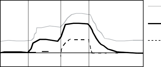
PACING THERAPIES
SENSORS AND TRENDING 5-15
Activity Threshold
MSR
Paced rate
LRL
Rest Stage 1 RestStage 2
Time
Lower threshold
setting
Higher threshold
setting
Nominal threshold
setting
This figure demonstrates the effect of increased or decreased Activity Threshold settings in
response to a theoretical two-stage exercise test.
Figure 5-5. Activity Threshold in exercise test
Reaction Time
Reaction Time determines how quickly the pacing rate will rise to a new level
once an increase in activity level is detected.
Reaction Time affects only the time required for a rate increase to occur. The
value selected determines the time required for the paced rate to move from
the LRL to the MSR for a maximum level of activity (Figure 5-6 on page 5-16
and Figure 5-7 on page 5-16).
• Short Reaction Time: results in a rapid increase in the pacing rate
• Long Reaction Time: results in a slower increase in the pacing rate
• Nominal setting: shown to be appropriate for the majority of patients in a
previous Guidant study; therefore, it is recommended for use in monitoring
the rate response prior to programming changes
- DRAFT -
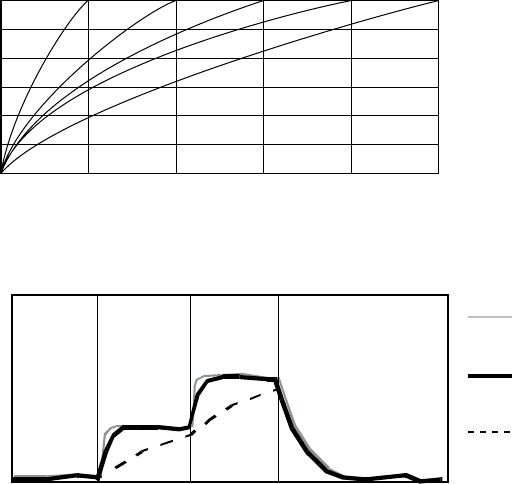
5-16 PACING THERAPIES
SENSORS AND TRENDING
Reaction Slopes
MSR
LRL
01020304050
Seconds
Paced rate
S
h
o
r
t
N
o
m
i
n
a
l
L
o
n
g
Figure 5-6. Reaction Time and paced rate
Reaction Time
MSR
LRL
Rest Stage 1 RestStage 2
Time
Shorter
Longer
Paced rate
Shorter
Reaction Time
Longer
Reaction Time
Nominal
Reaction Time
Figure 5-7. Reaction Time in exercise test
Programming Reaction Time for Normal Settings also changes the
corresponding selection for Post-Therapy Settings.
Response Factor (Accelerometer)
Response Factor (accelerometer) determines the pacing rate that will occur
above the LRL at various levels of patient activity (Figure 5-8 on page 5-17).
• High Response Factor––results in less activity required for the pacing rate
to reach the MSR
• Low Response Factor––results in more activity required for the pacing
rate to reach the MSR
• Nominal setting––shown to be appropriate for the majority of patients in a
previous Guidant study; therefore, it is recommended for use in monitoring
the rate response prior to programming changes
- DRAFT -
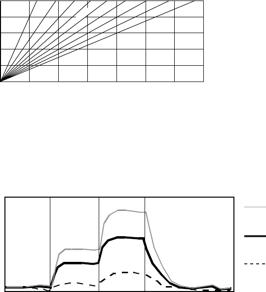
PACING THERAPIES
SENSORS AND TRENDING 5-17
Rate Response Slopes
16 14 12 10 8 6 4 2 1
MSR
LRL
Low High
Activity
Paced rate
Nominal
Figure 5-8. Response Factor and paced rate
The pacing rate achieved can be limited either by the detected activity level or
the programmed MSR. If the detected activity level results in a steady-state rate
below the MSR, the pacing rate can still increase when the detected activity
levels increase (Figure 5-9 on page 5-17).
Response Factor
MSR
Paced rate
LRL
Rest Stage 1 Rest Stage 2
Time
Higher Response
Setting
Lower Response
setting
Nominal
Response Setting
Lower
Higher
This figure shows the effect of higher and lower settings during a theoretical two-stage exercise test.
Figure 5-9. Response Factor in exercise test
Programming the LRL up or down moves the entire response up or down
without changing its shape. The steady-state response is independent of the
programmed reaction and recovery times.
The Passive setting can be used to allow accelerometer trending without a rate
response. In this setting, the Brady Mode is programmed to a non–rate-adaptive
mode and the Recording Method for sensor trending is not programmed to Off.
Programming Response Factor for Normal Settings also changes the
corresponding selection for Post-Therapy Settings.
- DRAFT -
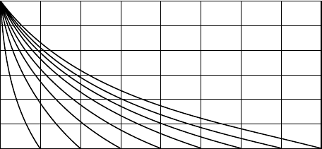
5-18 PACING THERAPIES
SENSORS AND TRENDING
Recovery Time
Recovery Time determines the time required for the paced rate to decrease
from the MSR to the LRL in the absence of activity. When patient activity
concludes, Recovery Time is used to prevent an abrupt decrease in pacing rate
(Figure 5-10 on page 5-18 and Figure 5-11 on page 5-19).
• Short Recovery Time––results in a faster decrease in pacing rate after
patient activity lowers or stops
• Long Recovery Time––results in a slower decrease in pacing rate after
patient activity lowers or stops
Recovery Curves
MSR
Paced rate
LRL
0246 161412108
Minutes
There are 15 settings available; only the even-numbered settings are shown.
Figure 5-10. Recovery Time and paced rate
- DRAFT -