Broadcom BRCM1030 802.11g WLAN PCI-E Mini Card User Manual book
Broadcom Corporation 802.11g WLAN PCI-E Mini Card book
Broadcom >
Contents
- 1. Users Manual
- 2. User Manual
- 3. Manual Statement
- 4. User manual 1 of 2
- 5. User manual 2 of 2
- 6. System User manual
- 7. Manual statement
- 8. User Manual Statement
- 9. Regulatory User Guide
- 10. Bear Manual
- 11. BixbyUG Manual
- 12. Welchs Manual
- 13. User Manual I71C
- 14. User Manual legal part
- 15. User Manual Q44C
- 16. OEM ODM Instruction
- 17. Manual 1
- 18. Manual 2
- 19. Manual 3
- 20. OEM installation guide
- 21. Host user manual
User Manual
www.dell.com | support.dell.com
Dell™ Studio 1535/1536
Quick Reference Guide
Model PP33L

Notes, Notices, and Cautions
NOTE: A NOTE indicates important information that helps you make better use of
your computer.
NOTICE: A NOTICE indicates either potential damage to hardware or loss of data
and tells you how to avoid the problem.
CAUTION: A CAUTION indicates a potential for property damage, personal injury,
or death.
If you purchased a Dell™ n Series computer, any references in this document to
Mcrosoft
®
Windows
®
operating systems are not applicable.
___________________
Information in this document is subject to change without notice.
© 2008 Dell Inc. All rights reserved.
Reproduction in any manner whatsoever without the written permission of Dell Inc. is strictly forbidden.
Trademarks used in this text: Dell, the DELL logo, Wi-Fi Catcher, YOURS IS HERE, DellConnect,
and MediaDirect are trademarks of Dell Inc.; Intel and Core are registered trademarks of Intel Corporation.;
AMD, AMD Turion, Athlon, Sempron, ATI Radeon and combinations thereof are trademarks of Advanced
Micro Devices, Inc.; Microsoft, Windows, and Windows Vista are either trademarks or registered
trademarks of Microsoft Corporation in the United States and/or other countries; Bluetooth is a
registered trademark owned by Bluetooth SIG, Inc. and is used by Dell under license.
Other trademarks and trade names may be used in this document to refer to either the entities claiming
the marks and names or their products. Dell Inc. disclaims any proprietary interest in trademarks and
trade names other than its own.
Model PP33L
March 2008 P/N F434C Rev. A00

Contents 3
Contents
Finding Information . . . . . . . . . . . . . . . . . . . . 7
1 About Your Computer . . . . . . . . . . . . . . . . 9
Front and Right View . . . . . . . . . . . . . . . . . . . 9
Back and Left View . . . . . . . . . . . . . . . . . . . 15
Bottom View . . . . . . . . . . . . . . . . . . . . . . . 19
Removing and Replacing the Battery . . . . . . . . . . 20
Removing and Replacing the Base Cover . . . . . . . 21
2 Specifications . . . . . . . . . . . . . . . . . . . . . 23
3 Troubleshooting . . . . . . . . . . . . . . . . . . . 33
Dell Technical Update Service . . . . . . . . . . . . . 33
Pre-Boot Self-Assessment (PSA)
Diagnostics and Dell 32 Bit Diagnostics . . . . . . . . 33
Dell Support Center . . . . . . . . . . . . . . . . . . . 37
Drive Problems . . . . . . . . . . . . . . . . . . . . . 38
Hard drive problems . . . . . . . . . . . . . . . . 38
Error Messages . . . . . . . . . . . . . . . . . . . . . 39

4Contents
Lockups and Software Problems . . . . . . . . . . . . 44
The computer does not start . . . . . . . . . . . . 44
The computer stops responding . . . . . . . . . . 44
A program stops responding or
crashes repeatedly . . . . . . . . . . . . . . . . . 44
A program is designed for an earlier
Microsoft® Windows® operating system . . . . . 45
A solid blue screen appears . . . . . . . . . . . . 45
Memory Problems . . . . . . . . . . . . . . . . . . . . 45
Power Problems . . . . . . . . . . . . . . . . . . . . . 46
Troubleshooting Software and Hardware Problems
in the Windows Vista® Operating System . . . . . . . 47
Restoring Your Operating System . . . . . . . . . . . . 48
Using Windows Vista System Restore . . . . . . . 48
4 Getting Help . . . . . . . . . . . . . . . . . . . . . . . 53
Obtaining Assistance . . . . . . . . . . . . . . . . . . 53
Technical Support and Customer Service . . . . . 54
DellConnect . . . . . . . . . . . . . . . . . . . . . 54
Online Services . . . . . . . . . . . . . . . . . . . 54
AutoTech Service . . . . . . . . . . . . . . . . . . 55
Automated Order-Status Service . . . . . . . . . 55
Problems With Your Order . . . . . . . . . . . . . . . . 55
Product Information . . . . . . . . . . . . . . . . . . . 55
Returning Items for Warranty Repair or Credit . . . . . 56
Before You Call . . . . . . . . . . . . . . . . . . . . . 56
Contacting Dell . . . . . . . . . . . . . . . . . . . . . 58

Contents 5
A Appendix . . . . . . . . . . . . . . . . . . . . . . . . . 59
FCC Notice (U.S. Only) . . . . . . . . . . . . . . . . . . 59
FCC Class B . . . . . . . . . . . . . . . . . . . . . 59
Macrovision Product Notice . . . . . . . . . . . . . . 60
Index . . . . . . . . . . . . . . . . . . . . . . . . . . . . . . . 61

6Contents

Finding Information 7
Finding Information
NOTE: Some features may be optional and may not ship with your computer. Some
features may not be available in certain countries.
NOTE: Additional information may ship with your computer.
Document/Media/Label Contents
Service Tag and Express Service Code
You can find this at the bottom of your
computer.
• Use the Service Tag to identify your
computer when you use
support.dell.com
or contact support.
• Enter the Express Service Code to direct
your call when contacting support.
Model Number
You can find this at the bottom of your
computer next to the service tag.
Model number of your computer.
Drivers and Utilities Media
• A diagnostic program for your computer
• Drivers for your computer
• Device documentation
• Notebook System Software (NSS)
Readme files may be included on your
Drivers and Utilities media to provide
last-minute updates about technical
changes to your computer or advanced
technical-reference material for
technicians or experienced users.
NOTE: Drivers and documentation updates
can be found at support.dell.com.
Setup Diagram How to setup your computer
Service Manual
Available at Dell Support Website -
support.dell.com
• How to remove and replace parts
• How to troubleshoot and solve
problems
Dell Technology Guide
Available in Windows Help and Support
(Start → Help and Support) and at
Dell Support Website - support.dell.com
• About your operating system
• Using and maintaining peripherals
• Understanding technologies such as
Internet, E-mail, and so on.

8Finding Information
Microsoft Windows License Label
You can find this label in the battery
compartment.
Your operating system product key.
NOTE: This label is available only for
systems with Microsoft operating system.
Dell Support Center
• Self Help (Troubleshooting, Security,
System Performance, Network/Internet,
Backup/Recovery, and Windows Vista)
• Alerts (technical support alerts relevant
to your computer)
• Assistance from Dell (Technical
Support with DellConnect™, Customer
Service, Training and Tutorials, How-To
Help with Dell on Call, and Online
Scan with PC CheckUp)
• About Your System (System
Documentation, Warranty
Information, System Information,
Upgrades & Accessories)
NOTE: The Dell Support Center features
available in your computer depends on the
configuration.
Dell QuickSet Help Information on network activity, the
hotkeys, and other items controlled by
Dell QuickSet
To view Dell QuickSet Help, right-click
the Dell QuickSet icon in the Windows
notification area.
Document/Media/Label Contents
About Your Computer 9
About Your Computer
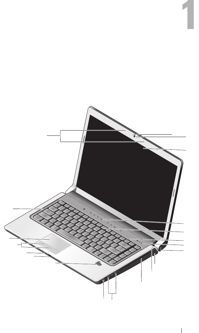
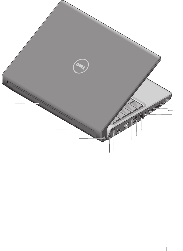
Front and Right View
4
5
8
2
15
14
3
6
9
10
11
17
18
20 1
7
19
16
12
13
10 About Your Computer
CAMERA INDICATOR —Indicates that the camera is on. Based on configuration
selections you made when ordering your computer, your computer may not include a
camera.
CAMERA —Built-in camera for video capture, conferencing, and chat. Based on
configuration selections you made when ordering your computer, your computer may
not include a camera.
DISPLAY —For more information on the display, see Dell Technology Guide.
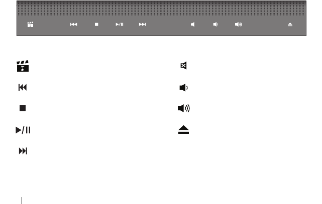
MEDIA CONTROL BUTTONS —Control CD, DVD, Blu-ray, and Media Player playback.
1 camera indicator (optional) 2 camera (optional)
3 display 4 media control buttons (9)
5 keyboard 6 num lock light
7 device status lights 8 power button
9 AC adapter connector 10 battery status light
11 optical drive 12 USB connectors (2)
13 IEEE connector 14 fingerprint reader (optional)
15 consumer IR 16 analog microphone
17 touch pad buttons (2) 18 touch pad
19 caps lock light 20 digital array microphones (optional)
Launch Dell MediaDirect Mute the sound
Play the previous track Turn the volume down
Stop Turn the volume up
Play or pause Eject the disc
Play the next track
About Your Computer 11
KEYBOARD —Backlit keyboard is an optional feature. If you have purchased the
backlit keyboard, you can change the settings through Dell QuickSet.
See Dell Technology Guide for more information on keyboard.
NUM LOCK LIGHT —Turns on when Num Lock is activated.
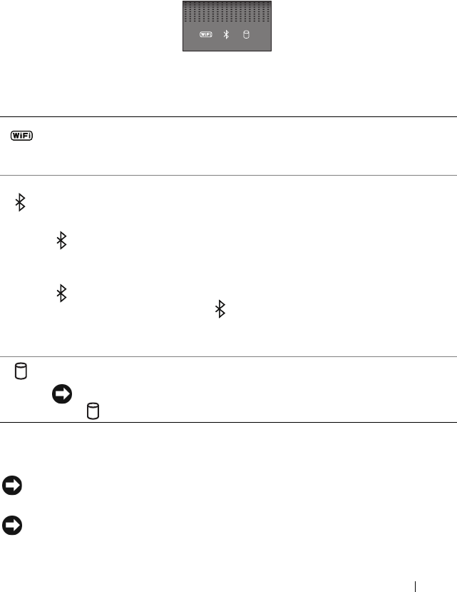
DEVICE STATUS LIGHTS
The lights located on the palm rest towards the front of the computer
indicate the following:
POWER BUTTON —Press the power button to turn on the computer or exit a power
management mode.
NOTICE: If the computer stops responding, press and hold the power button until
the computer turns off completely (may take several seconds).
NOTICE: To avoid losing data, turn off your computer by performing a Microsoft®
Windows® operating system shutdown rather than by pressing the power button.
WiFi status light – Turns on when wireless networking is enabled. To enable
or disable wireless networking, use the wireless switch (see "wireless on/off
switch" on page 17).
Bluetooth® status light – Turns on when a card with Bluetooth wireless
technology is enabled.
NOTE: The card with Bluetooth wireless technology is an optional feature. The
light turns on only if you ordered the card with your computer. For more
information, see the documentation that came with your card.
To turn off only the Bluetooth wireless technology functionality, right-click the
icon in the notification area, and then click Disable Bluetooth Radio. To
turn it back on, right-click the icon in the notification area, and then
click Enable Bluetooth Radio.
To quickly enable or disable all wireless devices, use the wireless switch.
Hard drive activity light – Turns on when the computer reads or writes data.
NOTICE: To avoid loss of data, never turn off the computer while the
light is flashing.
12 About Your Computer
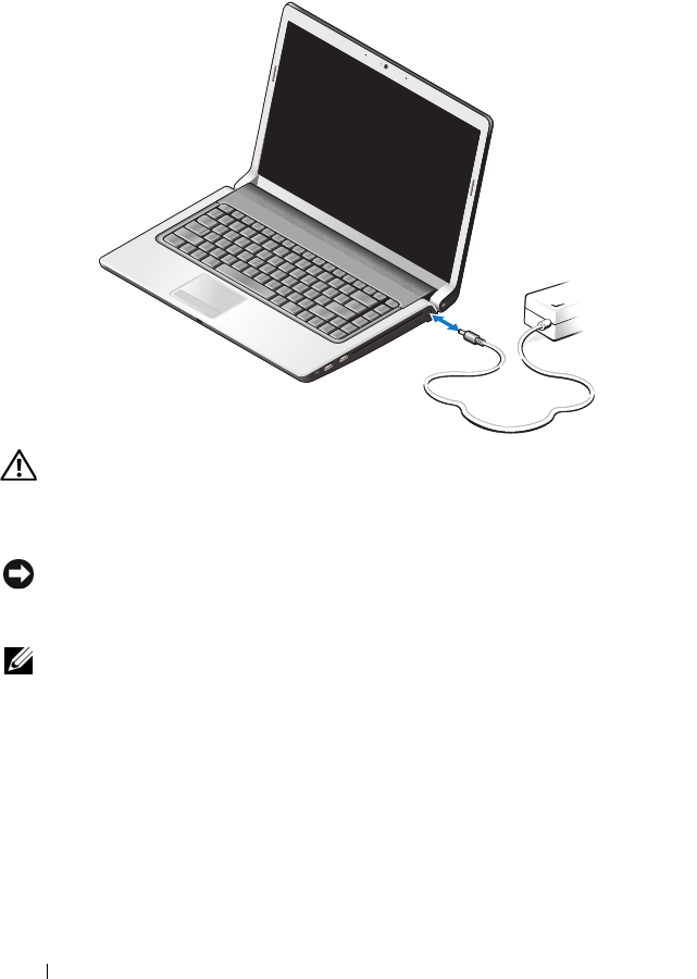
AC ADAPTER CONNECTOR —Attaches an AC adapter to the computer.
The AC adapter converts AC power to the DC power required by the computer.
You can connect the AC adapter with your computer turned on or off.
CAUTION: The AC adapter works with electrical outlets worldwide. However,
power connectors and power strips vary among countries. Using an incompatible
cable or improperly connecting the cable to the power strip or electrical outlet
may cause fire or equipment damage.
NOTICE: When you disconnect the AC adapter cable from the computer, grasp the
connector, not the cable itself, and pull firmly, but gently to help prevent damage to
the cable.
NOTE: Plug the power cord and the adapter firmly in, and ensure that the
green LED is on.
BATTERY STATUS LIGHT —Turns on steadily or blinks to indicate battery charge status.
If the computer is connected to an electrical outlet, the battery status light operates as
follows:
– Solid white: The battery is charging and has attained sufficient charge or the battery
is completely charged
– Off: The battery is adequately charged (or the computer is turned off).
– Solid orange: The battery charge is low.
– Flashing orange: The battery charge is critically low.

About Your Computer 13
OPTICAL DRIVE —For more information about the optical drive,
see Dell Technology Guide.
NOTE: The optical drive supports standard circular 12.7 cm discs. Irregularly
shaped discs or discs smaller than 12.7 cm are not supported.
USB CONNECTORS
IEEE 1394 CONNECTOR —Connects devices supporting IEEE 1394a high-speed
transfer rates, such as some digital video cameras.
FINGERPRINT READER (OPTIONAL)—Helps to keep your Dell™ computer secure.
When you slide your finger over the reader, it uses your unique fingerprint to
authenticate your user identity. The controlling security management software,
DigitalPersona Personal, displays a fingerprint reader icon in the system tray that
shows whether the reader is ready for use, and provides convenient access to a few
major components and features on its menu. When the reader is ready to scan
fingerprints, the reader icon appears normally. Otherwise, a red X displays over the
reader icon. The icon also flashes in red color when a fingerprint scan is being
processed.
For more information on how to activate and use DigitalPersona Personal, click Start →
Programs → DigitalPersona Personal. The following sub-items are available in this
menu:
•
Fingerprint Enrollment Wizard
- To enroll your fingerprint
•
Fingerprint Logon Manager
- To add, remove or modify properties related to
Fingerprint Logons
•
Import and Export Wizard
- To export fingerprint information into a file for the further
import on another computer, or for the use as a user-level backup. This functionality
allows avoiding the need to re-enter the data when upgrading your computer or while
adding a fingerprint reader to a second computer. However, you need to enroll your
fingerprints on the computer that you are exporting the DigitalPersona Personal data to.
•
Properties
- To configure DigitalPersona Personal Settings and product behavior. For
more information, see
DigitalPersona Online Help
→
Using DigitalPersona Personal
Features
→
General Settings
.
•
Check for Updates
- To deliver and install software updates and also for updating
options. You must have an Internet connection to use this feature. You can either
check for updates manually or automatically.
Connect USB devices, such as a mouse, keyboard, or printer.

14 About Your Computer
•
Help
- HTML-based Help.
CONSUMER IR — Infrared sensor for using the Dell Travel Remote.
ANALOG MICROPHONE —Integrated single microphone for conferencing and chat.
NOTE: Analog microphone is present only when you have not ordered for the
optional camera and digital array microphones.
TOUCH PAD BUTTONS —Use these buttons much like the buttons on a mouse when
you use the touch pad to move the cursor on the display.
TOUCH PAD —Provides the functionality of a mouse.
CAPS LOCK LIGHT —turns on when Caps Lock is activated.
DIGITAL ARRAY MICROPHONES —Higher quality built-in microphones for
conferencing and chat. These microphones filter noise and provide better sound
quality
NOTE: Digital array microphones are optional and may not be present in your
computer unless you have ordered for the optional camera. Instead, your computer
will have an integrated single analog microphone.
About Your Computer 15
Back and Left View
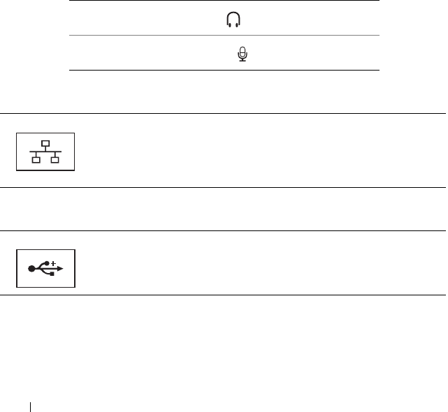
1 ExpressCard slot 2 8-in-1 media card reader
3 headphone connectors (2) 4 microphone connector
5 network connector (RJ-45) 6 USB connector
7 eSATA connector* 8 VGA connector
9 HDMI connector 10 wireless switch
11 security cable slot 12 Wi-Fi catcher network locator
13 air vents 14 battery
* Studio 1535 systems have an additional USB connector instead of an eSATA connector.
5
6
7
8
9
10
11
12
13
14
1
2
3
4
16 About Your Computer
EXPRESSCARD SLOT —Supports one ExpressCard. The computer ships with a
plastic blank installed in the slot.
8-IN-1 MEDIA CARD READER —Provides a fast and convenient way to view and share
digital photos, music, and videos stored on a media memory card. The computer ships
with a plastic blank installed in the slot. The 8-in-1 memory card reader reads the
following digital media memory cards:
• Secure Digital (SD) memory card
• Secure Digital Input Output (SDIO) card
• MultiMediaCard (MMC)
•Memory Stick
• Memory Stick PRO
• xD-Picture Card
• Hi Speed-SD
• Hi Density-SD
AUDIO CONNECTORS
NETWORK CONNECTOR (RJ-45)
USB CONNECTORS
Attach headphones to the connector
Attach a microphone to the connector
Connects the computer to a network. The two lights next to the
connector indicate status and activity for wired network connections.
For information on using the network adapter, see the device user’s
guide supplied with your computer.
Connect USB devices, such as a mouse, keyboard, or printer.
About Your Computer 17
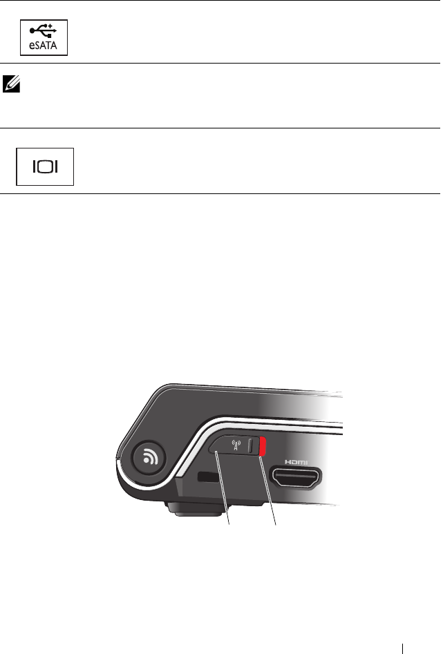
ESATA CONNECTOR
NOTE: The eSATA connector is available only in Studio 1536.
VGA CONNECTOR
HDMI CONNECTOR —HDMI (High-Definition Multimedia Interface) connector
carries an uncompressed all digital signal to produce hi-definition video and audio.
WIRELESS ON/OFF SWITCH —Use this switch to rapidly turn off or on any wireless
devices such as WLAN cards and internal cards with Bluetooth wireless technology.
The wireless switch on your Dell computer uses the Dell Wi-Fi Catcher™ network
locator (see "Wi-Fi Catcher™ network locator" on page 18) to scan for wireless networks
in your vicinity. The wireless switch is enabled and configured for use when your
computer is shipped to you. You can change the settings through Dell QuickSet or the
BIOS (system setup program).
Connect eSATA compatible storage devices, such as external hard
disk drives or optical drives.
Connects video devices, such as a monitor.
1off Disables wireless devices
2on Enables wireless devices
12

18 About Your Computer
SECURITY CABLE SLOT —Lets you attach a commercially available antitheft device
to the computer.
WI-FI CATCHER™ NETWORK LOCATOR —Press this button for a few seconds to scan
specifically for wireless networks in your vicinity.
The Wi-Fi Catcher Network Locator has a light that operates as follows:
- Flashing white: Searching for networks
- Solid white for 10 seconds and then turns off: Network found
- Off (flashing white turns off after 10 blinks): No signal found
The Wi-Fi Catcher Network Locator is enabled and configured for use when your
computer is shipped to you. For more information on the Wi-Fi Catcher Network
Locator and to enable the feature through Dell QuickSet, right-click the QuickSet
icon in the notification area, and then select Help.
AIR VENTS —The computer uses an internal fan to create airflow through the vents,
which prevents the computer from overheating. The fan automatically turns on when
the computer gets hot. Fan noise is normal and does not indicate a problem with the
fan or the computer.
CAUTION: Do not block, push objects into, or allow dust to accumulate in the air
vents. Do not store your computer in a low-airflow environment, such as a closed
briefcase, while it is running. Restricting the airflow can damage the computer or
cause a fire.
About Your Computer 19
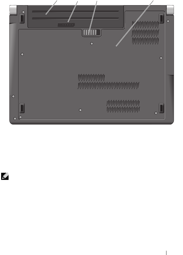
Bottom View
BATTERY —When a battery is installed, you can use the computer without
connecting the computer to an electrical outlet.
NOTE: Connecting the computer to an electrical outlet through the AC adapter will
present the brightest picture as well as charge the battery.
BATTERY CHARGE/HEALTH GAUGE —Provides information on the battery charge.
BATTERY RELEASE LATCH —Releases the battery.
BASE COVER —Compartment that contains the processor, hard drive, memory modules,
WLAN, WWAN, or Ultra Wideband (UWB) cards.
1 battery 2 battery charge/health gauge
3 battery release latch 4 base cover
3 41 2
20 About Your Computer
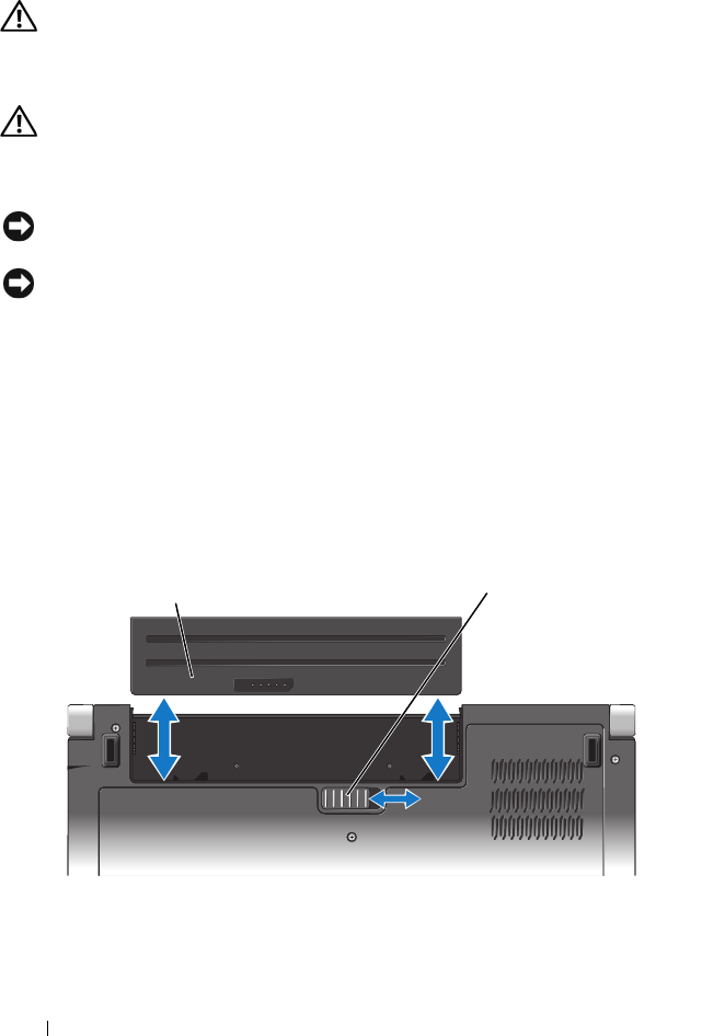
Removing and Replacing the Battery
CAUTION: Using an incompatible battery may increase the risk of fire or
explosion. Replace the battery only with a compatible battery purchased from
Dell. The battery is designed to work with your Dell computer. Do not use batteries
from other computers with your computer.
CAUTION: Before performing these procedures, turn off the computer, disconnect
the AC adapter from the electrical outlet and the computer, disconnect the modem
from the wall connector and the computer, and remove any other external cables
from the computer.
NOTICE: You must remove all external cables from the computer to avoid possible
connector damage.
NOTICE: If you choose to replace the battery with the computer in Sleep state, you
have up to 1 minute to complete the battery replacement before the computer shuts
down and loses any unsaved data.
To remove the battery:
1
Ensure that the computer is turned off.
2
Turn the computer over.
3
Slide the battery release latch toward the side of the computer until it is
engaged.
4
Slide the battery out of the bay.
To replace the battery, slide the battery into the bay until it clicks into place.
1 battery 2 battery release latch
2
1

About Your Computer 21
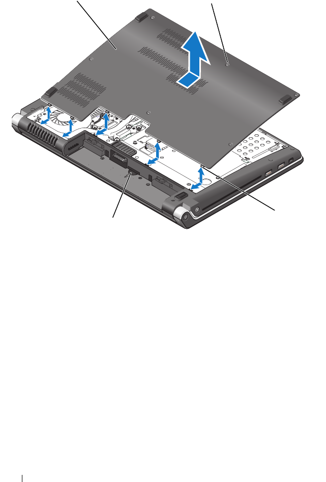
Removing and Replacing the Base Cover
CAUTION: Before working inside your computer, follow the safety instructions
that shipped with your computer.
CAUTION: Before performing this procedures, turn off the computer, disconnect
the AC adapter from the electrical outlet and the computer, disconnect the modem
from the wall connector and the computer, and remove any other external cables
from the computer.
NOTICE: To avoid electrostatic discharge, ground yourself by using a wrist
grounding strap or by periodically touching an unpainted metal surface (such as a
connector on the back of the computer).
To remove the base cover:
1
Ensure that the computer is turned off.
2
Remove the battery (see "Removing and Replacing the Battery" on page 20).
3
Loosen the six captive screws on the base cover and lift the cover off the
computer at an angle as shown in the picture.
CAUTION: Do not touch the processor thermal-cooling assembly. Processor
components should be removed only by trained support personnel.
For instructions on removal and replacement of parts, see the Service Manual
at support.dell.com.
To replace the base cover:
1
Align the tabs on the base cover to the bottom of the computer.
2
Replace and tighten the six captive screws on the base cover.
3
Replace the battery (see "Removing and Replacing the Battery" on page 20).
22 About Your Computer
1 base cover 2 captive screws (6)
3 tabs 4 SIM card slot
2
1
3
4

Specifications 23
Specifications
NOTE: Offerings may vary by region. For more information regarding the
configuration of your computer, click Start , click Help and Support, and then
select the option to view information about your computer.
Processor
Processor type Studio 1535:
•Intel
®
Celeron
™
Processor
•Intel
®
Pentium™ Processor
•Intel
®
Core™ 2 Processor
Studio 1536:
•AMD
®
Sempron™
Processor
•AMD
®
Athlon™
Dual Core Processor
•AMD
®
Turion™
Dual Core Processor
•AMD
®
Turion™ Ultra Dual Core Processor
L1 cache 64 KB (Intel - 32 KB per core)
256 KB (AMD - 128 KB per core)
L2 cache 512 KB (AMD Sempron)
1 MB (Intel Pentium, Intel Celeron, AMD
Athlon, AMD Turion)
2 MB or 3 MB (Intel Core 2 Duo, AMD
Turion Ultra)
6 MB (Intel Core 2 Duo)
External bus frequency
HyperTransport (AMD)
533 MHz (Intel Celeron, Intel Pentium
Dual Core)
667 MHz/800 MHz (Intel Core 2 Duo)
2.66 GHz (AMD Turion Ultra Dual-Core)

24 Specifications
System Information
System chipset Intel GM/PM 965 (Studio 1535)
AMD M780G (Studio 1536)
Data bus width 64 bits
DRAM bus width dual-channel (2) 64-bit buses
Processor address bus width 32 bits
Flash EPROM 2 MB
Graphics bus PCI-E X16
PCI bus 32 bits
ExpressCard
NOTE: The ExpressCard slot is designed only for ExpressCards. It does NOT support
PC Cards.
ExpressCard controller Intel ICH8M (Studio 1535)
AMD M780G (Studio 1536)
ExpressCard connector one ExpressCard slot (54 mm)
Cards supported ExpressCard/34 (34 mm)
ExpressCard/54 (54 mm)
1.5 V and 3.3 V
ExpressCard connector size 26 pins

Specifications 25
8-in-1 Memory Card Reader
8-in-1 memory card controller Ricoh R5C833
8-in-1 memory card connector 8-in-1 combo card connector
Cards supported
• Secure Digital (SD)
•SDIO
• MultiMediaCard (MMC)
•Memory Stick
• Memory Stick PRO
• xD-Picture Card
• Hi Speed-SD
• Hi Density-SD
Memory
Memory module connector two user-accessible SODIMM connectors
Memory module capacities 512 MB, 1 GB, 2 GB
Memory type 800 MHz SODIMM DDR2
Minimum memory 512 MB (single channel)
Maximum memory 4 GB (dual channel 2G x2)
NOTE: In order to take advantage of the dual channel bandwidth capability, both
memory slots must be populated and must match in size.
NOTE: The available memory displayed does not reflect the complete maximum
memory installed because some memory is reserved for system files.
Ports and Connectors
Audio microphone connector, two stereo
headphone/speakers connector
IEEE 1394a 4-pin serial connector (optional)
Consumer IR sensor compatible with Philips RC6
(receive only)
Mini Card two Type IIIA Mini Card slots, one half-size
Mini Card slot
Network adapter RJ-45 port

26 Specifications
eSATA one four pin eSATA/USB combo connector
(available only on Studio 1536)
USB four 4-pin USB 2.0-compliant connector
(Studio 1535)
three 4-pin USB 2.0-compliant connector
(Studio 1535)
Video 15-hole connector
HDMI 19 pin
Communications
Modem:
Ty p e
External V.92 56K USB Modem
Controller
Hardware modem
Interface
Universal Serial Bus (USB)
Network adapter 10/100/1000 Ethernet LAN on system board
Wireless internal WLAN (half-size Mini-Card),
WWAN, Mini-Card with Bluetooth®
wireless technology, UWB (optional) Mini-
Cards
WWAN ExpressCard
Bluetooth® wireless technology
Video
Discrete:
Video type
integrated on system board
Video controller
ATI Mobility Radeon HD 3450
Video memory
GDDR2 256MB
Ports and Connectors (continued)

Specifications 27
UMA:
Video type
integrated on system board
Video controller
Mobile Intel GMA X3100, ATI Radeon™
HD 3200 Graphics
Video memory
Intel: Up to 358 MB of shared memory
AMD: Up to 256 MB of shared memory (32
MB dedicated local frame buffer)
LCD interface
LVDS
TV support
HDMI 1.2
Audio
Audio type IDT 92HD73C High Definition Audio
codec
Audio controller 5.1 channel High Definition Audio
Stereo conversion 24-bit (analog-to-digital and digital-to-analog)
Interfaces:
Internal
Intel High Definition Audio
External
microphone-in connector, two stereo
headphones/speakers connector
Speaker two 4-ohm speakers
Internal speaker amplifier 2 Watt per channel into 4 ohms
Volume controls program menus, media control buttons
Video (continued)

28 Specifications
Display
Type (TrueLife) 15.4-inch CCFL WXGA Anti-Glare
15.4-inch CCFL WXGA+ with TrueLife
15.4-inch CCFL WUXGA with TrueLife
15.4-inch WXGA+WLED with TrueLife
Dimensions:
Height
207 mm (8.14 in)
Width
331.2 mm (13.03 in)
Diagonal
391.2 mm (15.4 in)
Maximum resolutions:
WXGA AG
1280 x 800 at 262 K colors
WXGA+ with TrueLife
1440 x 900 at 262 K colors
WUXGA
+
with TrueLife
1600 x 1200 at 262 K colors
Refresh rate 60 Hz
Operating angle 0° (closed) to 140°
Viewing angles:
Horizontal
±40° (WXGA AG)
±55° (WXGA+
with TrueLife
)
±55° (WUXGA+
with TrueLife
)
Vertical
+15°/–30° (WXGA AG)
±45° (WXGA+
with TrueLife
)
±45° (WUXGA+
with TrueLife
)
Pixel pitch:
WXGA AG
0.258 mm
WXGA+ with TrueLife
0.2304 mm
WUXGA
+
with TrueLife
0.1725 mm
Controls brightness can be controlled through keyboard
shortcuts (see Dell Technology Guide for more
information.)

Specifications 29
Media
Drive DVD+/-RW
Interface Roxio Creator 10 DE and Roxio Creator 10
Premier - Ultimate
Dell MediaDirect™ 4.0
Keyboard
Number of keys 86 (U.S. and Canada); 102 (Europe); 105
(Japan); 104 (Brazil)
Layout QWERTY/AZERTY/Kanji
NOTE: Backlit keyboard is optional
Camera (optional)
Pixel 2.0 mega pixel
Video Resolution 320x240 ~1600x1200 (640x480 at 30fps)
Diagonal Viewing Angle 66°
Touch Pad
X/Y position resolution
(graphics table mode) 240 cpi
Size:
Width
73.09-mm (2.87-in) sensor-active area
Height
40.09-mm (1.57-in) rectangle

30 Specifications
Battery
Type 9-cell "smart" lithium ion
6-cell "smart" lithium ion
4-cell "smart" lithium ion
Dimensions:
Depth
48.3 mm (1.9 in) (4/6/9 cell)
Height
20.4 mm (0.8 in) (4/6 cell)
37.8 mm (1.5 in) (9 cell)
Width
206.6 mm (8.13 in) (4/6 cell)
284.9 mm (11.2 in) (9 cell)
Weight 0.24 kg (0.54 lb) (4 cell)
0.34 kg (0.75 lb) (6 cell)
0.5 kg (1.1 lb) (9 cell)
Voltage 11.1 VDC (6/9 cell)
14.8 VDC (4 cell)
Charge time (approximate):
Computer off
4 hours
Operating time Battery operating time varies depending on
operating conditions and can be significantly
reduced under certain power-intensive
conditions.
See Dell Technology Guide for more
information on battery life.
Life span (approximate) 300 discharge/charge cycles
Temperature range:
Operating
0° to 35°C (32° to 95°F)
Storage
–40° to 65°C (–40° to 149°F)
Coin-cell battery CR-2032

Specifications 31
AC Adapter
Input voltage 100–240 VAC
Input current (maximum) 1.5 A
Input frequency 50–60 Hz
Output current
65 W
90 W
3.34 A (continuous)
4.34 A (peak for 4-second pulse)
4.62 A (continuous)
5.62 A (peak for 4-second pulse)
Output power 65 W or 90 W
Rated output voltage 19.5 VDC
Dimensions:
65 W
Height
28.2 mm (1.11 in)
Width
57.9 mm (2.28 in)
Length
137.2 mm (5.4 in)
90 W
Height
34.2 mm (1.35 in)
Width
60.9 mm (2.39 in)
Length
153.42 mm (6.04 in)
Weight (without cables)
65 W
0.29 kg (0.64 lb)
90 W
0.345 kg (0.76 lb)
Temperature range:
Operating
0° to 35°C (32° to 95°F)
Storage
–40° to 65°C (–40° to 149°F)
Connector types:
DC connector
3 pin, 7.4 mm plug
AC connector
2 pin - C7 (Japan only)
3 pin - C5

32 Specifications
Physical
Height 25.3 mm to 38.5 mm (1.0 in to 1.51 in)
Width 355 mm (13.98 in)
Depth 261.9 mm (10.31 in)
Weight (with 4-cell battery):
Configurable to less than
2.68 kg (5.91 lb)
Environmental
Temperature range:
Operating
0° to 35°C (32° to 95°F)
Storage
–40° to 65°C (–40° to 149°F)
Relative humidity (maximum):
Operating
10% to 90% (noncondensing)
Storage
5% to 95% (noncondensing)
Maximum vibration (using a random
vibration spectrum that simulates
user environment):
Operating
0.66 GRMS
Storage
1.3 GRMS
Maximum shock (Measured with
hard drive in operating but not
accessing data status and a 2-ms half-
sine pulse for operating. Also
measured with hard drive in head-
parked position and a 2-ms halfsine
pulse for storage):
Operating
110 G
Storage
160 G
Altitude (maximum):
Operating
–15.2 to 3048 m (–50 to 10,000 ft)
Storage
–15.2 to 10,668 m (–50 to 35,000 ft)
Airborne containment level G2 or lower as defined by ISA-S71.04-1985

Troubleshooting 33
Troubleshooting
Dell Technical Update Service
The Dell Technical Update service provides proactive e-mail notification of
software and hardware updates for your computer. This service is free and can
be customized for content, format, and frequency of notifications.
To enroll for the Dell Technical Update service, go to
support.dell.com/technicalupdate.
Pre-Boot Self Assessment (PSA) Diagnostics and
Dell 32 Bit Diagnostics
CAUTION: Before you begin any of the procedures in this section, follow the
safety instructions that shipped with your computer.
Diagnostics Available
Depending on which Dell computer you have purchased there may be
additional extended Dell 32 Bit Diagnostics available on the hard drive in a
Utility Partition that provides additional troubleshooting.
When to Use PSA Diagnostics and Dell 32 Bit Diagnostics
If you experience a problem with your computer, perform the checks in
"Lockups and Software Problems" on page 44 and run PSA Diagnostics and
Dell 32 Bit Diagnostics before you contact Dell for technical assistance.
It is recommended that you print these procedures before you begin.
NOTE: PSA and 32 Bit Dell Diagnostics operate only on Dell computers.
Enter system setup, review your computer’s configuration information, and
ensure that the device you want to test displays in system setup and is active
(for more information on system setup, see Dell Technology Guide).
Start the Dell 32 Bit Diagnostics from your hard drive or from your Drivers and
Utilities media.

34 Troubleshooting
Starting PSA Diagnostics From Your Computer
NOTE: If your computer does not display a screen image, contact Dell (see
"Contacting Dell" on page 58).
NOTE: Troubleshooting using Dell 32 Bit Diagnostics through the Utility Partition,
referenced in this section, may or may not be available in your computer.
1
Ensure that the computer is connected to an electrical outlet.
2
Turn on (or restart) your computer.
3
Start PSA Diagnostics in one of the following two ways:
a
When the DELL™ logo appears, press <F12> immediately. Select
Diagnostics from the boot menu, and then press <Enter>.
NOTE: If you wait too long and the operating system logo appears, continue
to wait until you see the Microsoft® Windows® desktop, then shut down your
computer and try again.
NOTE: Before attempting option B, the computer must be turned off.
b
Press and hold the <Fn> key while powering the computer on.
Follow the prompts on the screen, select
Diagnostics
to start the PSA suite
of tests. The computer then runs the Pre-boot Self Assessment, a series of
initial tests of your system board, keyboard, hard drive, and display.
• During the assessment, provide inputs when prompted.
• If a failure is detected, the computer stops and beeps. To stop the
assessment and restart the computer, press <n>; to continue to the
next test, press <y>; to retest the component that failed, press <r>.
• If failures are detected during the Pre-boot System Assessment, write
down the error code(s) and contact Dell.
If the Pre-boot System Assessment completes successfully and your system
has 32 Bit Diagnostics, you receive the message
Booting Dell
Diagnostics Utility Partition. Press any key to
continue
.
4
Press any key to start the Dell 32 Bit Diagnostics.

Troubleshooting 35
Starting the Dell 32 Bit Diagnostics From the Drivers and Utilities Media
NOTE: Depending on which Dell computer you have purchased there may not be
an additional extended Dell 32 Bit Diagnostics available on the Drivers and Utilities
media referenced in this section.
1
Insert your
Drivers and Utilities
media.
2
Shut down and restart the computer.
3
When the DELL logo appears, press <F12> immediately.
NOTICE: Keyboard failure may result when a key on the keyboard is held
down for extended periods of time. To avoid possible keyboard failure, press and
release <F12> in even intervals until the boot device menu appears.
4
At the boot device menu, use the up- and down-arrow keys to highlight
CD/DVD/CD-RW
, and then press <Enter>.
NOTE: The Quickboot feature changes the boot sequence for the current
boot only. Upon restart, the computer boots according to the boot sequence
specified in system setup.
5
Select the
Boot from CD-ROM
option from the menu that appears, and
then press <Enter>.
6
Ty p e
1
to start the
Drivers and Utilities
menu, and then press <Enter>.
7
Select
Run the 32 Bit Dell Diagnostics
from the numbered list. If multiple
versions are listed, select the version appropriate for your computer.
8
At the Dell Diagnostics
Main Menu
, select the test you want to run.
NOTE: Write down the error codes and problem descriptions exactly as they
appear and follow the instructions on the screen.
9
After all tests have completed, close the test window to return to the Dell
Diagnostics
Main
Menu
.
10
Remove your
Drivers and Utilities
media and close the
Main Menu
window
to exit Diagnostics. Restart the computer.

36 Troubleshooting
Dell Diagnostics Main Menu
After the Dell Diagnostics loads and the Main Menu screen appears, click the
button for the option you want.
NOTE: It is recommended that you select Test System to run a complete test
on your computer.
After you have selected the Test System option from the main menu, the
following menu appears.
NOTE: It is recommended that you select Extended Test from the menu
below to run a more thorough check of the devices in the computer.
For any problem encountered during a test, a message appears with an error
code and a description of the problem. Write down the error code and problem
description exactly as it appears and follow the instructions on the screen. If you
cannot resolve the problem, contact Dell (see "Contacting Dell" on page 58).
NOTE: The Service Tag for your computer is located at the top of each test screen.
When contacting Dell support, have your Service Tag ready.
Option Function
Test Memory Run the stand-alone memory test
Test System Run System Diagnostics
Exit Exit Diagnostics
Option Function
Express Test Performs a quick test of system devices. The test typically
takes 10 to 20 minutes and requires no interaction on your
part. Run Express Test first to increase the possibility of
tracing the problem quickly.
Extended Test Performs a thorough check of system devices. The test
typically takes an hour or more and periodically requires your
input to answer specific questions.
Custom Test Tests a specific device in the system and can be used to
customize the tests you want to run.
Symptom Tree Lists a number of common symptoms and allows you to select
a test based on the symptom of the problem you are having.

Troubleshooting 37
The following tabs provide additional information for tests run from the
Custom Test or Symptom Tree option:
Dell Support Center
The Dell Support Center helps you find the service, support and system-specific
information you need. For more information about Dell Support Center and
available support tools, click the Services tab at support.dell.com.
Click on the icon in the taskbar to run the application. The home page
provides links to access:
• Self Help (Troubleshooting, Security, System Performance,
Network/Internet, Backup/Recovery, and Windows Vista)
• Alerts (technical support alerts relevant to your computer)
• Assistance from Dell (Technical Support with DellConnect™, Customer
Service, Training and Tutorials, How-To Help with Dell on Call, and
Online Scan with PCCheckUp)
• About Your System (System Documentation, Warranty Information,
System Information, Upgrades & Accessories)
The top of the Dell Support Center home page displays your system’s model
number along with its service tag and express service code.
Tab Function
Results Displays the results of the test and any error conditions
encountered.
Errors Displays error conditions encountered, error codes, and the
problem description.
Help Describes the test and any requirements for running the test.
Configuration Displays your hardware configuration for the selected device.
The Dell Diagnostics obtains configuration information for
all devices from system setup, memory, and various internal
tests, and it displays the information in the device list in the
left pane of the screen. The device list may not display the
names of all the components installed on your computer or
all devices attached to your computer.
Parameters Allows you to customize the test by changing the test settings.

38 Troubleshooting
For more information on Dell Support Center, see the Dell Technology
Guide. It is available in Windows Help and Support (Start → Help and
Support) and at Dell Support Website.
Drive Problems
CAUTION: Before you begin any of the procedures in this section, follow the
safety instructions that shipped with your computer.
Fill out the "Diagnostics Checklist" on page 57 as you complete these checks.
ENSURE THAT MICROSOFT® WINDOWS® RECOGNIZES THE DRIVE —
• Click
Start
→
Computer
.
If the drive is not listed, perform a full scan with your antivirus software to
check for and remove viruses. Viruses can sometimes prevent Windows from
recognizing the drive.
TEST THE DRIVE —
• Insert another CD, DVD, or BD to eliminate the possibility that the
original media is defective.
• Insert a bootable media and restart the computer.
CLEAN THE DRIVE OR DISK —See Dell Technology Guide.
CHECK THE CABLE CONNECTIONS
CHECK FOR HARDWARE INCOMPATIBILITIES —See Dell Technology Guide for
instructions on troubleshooting software and hardware problems.
RUN THE DELL DIAGNOSTICS —See "Pre-Boot Self Assessment (PSA)
Diagnostics and Dell 32 Bit Diagnostics" on page 33.
Hard drive problems
ALLOW THE COMPUTER TO COOL BEFORE TURNING IT ON —A hot hard drive may
prevent the operating system from starting. Try allowing the computer to
return to room temperature before turning it on.
RUN CHECK DISK —
1
Click
Start
→
Computer
.
2
Right-click
Local Disk (C:)
.

Troubleshooting 39
3
Click
Properties
→
Tools
→
Check Now
.
NOTE: The User Account Control window may appear. If you are an
administrator on the computer, click Continue; otherwise, contact your
administrator to continue the desired action.
4
Click to check
Scan for and attempt recovery of bad sectors
, and then
click
Start
.
Error Messages
Fill out the "Diagnostics Checklist" on page 57 as you complete these checks.
CAUTION: Before you begin any of the procedures in this section, follow the
safety instructions that shipped with your computer.
If the message is not listed, see the documentation for the operating system
or the program that was running when the message appeared.
AUXILIARY DEVICE FAILURE —The touch pad or external mouse may be faulty.
For an external mouse, check the cable connection. If the problem persists,
contact Dell (see "Contacting Dell" on page 58).
BAD COMMAND OR FILE NAME —Ensure that you have spelled the command
correctly, put spaces in the proper place, and used the correct pathname.
CACHE DISABLED DUE TO FAILURE —The primary cache internal to the
microprocessor has failed. Contact Dell (see "Contacting Dell" on page 58).
CD DRIVE CONTROLLER FAILURE —The CD drive does not respond to
commands from the computer (see "Drive Problems" on page 38).
DATA ERROR —The hard drive cannot read the data (see "Drive Problems" on
page 38).
DECREASING AVAILABLE MEMORY —One or more memory modules may be
faulty or improperly seated. Reinstall the memory modules and, if necessary,
replace them (see Service Manual for instructions to replace memory
modules).
DISK C: FAILED INITIALIZATION —The hard drive failed initialization. Run the
hard drive tests in the Dell Diagnostics (see "Pre-Boot Self Assessment (PSA)
Diagnostics and Dell 32 Bit Diagnostics" on page 33).
DRIVE NOT READY —The operation requires a hard drive in the bay before it
can continue. Install a hard drive in the hard drive bay.

40 Troubleshooting
EXTENDED MEMORY SIZE HAS CHANGED —The amount of memory recorded in
NVRAM does not match the memory installed in the computer. Restart the
computer. If the error appears again, contact Dell.
THE FILE BEING COPIED IS TOO LARGE FOR THE DESTINATION DRIVE —The file
that you are trying to copy is too large to fit on the disk, or the disk is full. Try
copying the file to a different disk or use a larger capacity disk.
A FILENAME CANNOT CONTAIN ANY OF THE FOLLOWING CHARACTERS: \ / : * ? “ <
> | — Do not use these characters in filenames.
GATE A20 FAILURE —A memory module may be loose. Reinstall the memory
modules and, if necessary, replace them.
GENERAL FAILURE —The operating system is unable to carry out the
command. The message is usually followed by specific information—for
example, Printer out of paper. Take the appropriate action.
HARD-DISK DRIVE CONFIGURATION ERROR —The computer cannot identify the
drive type. Shut down the computer, remove the hard drive, and boot the
computer from a CD. Then, shut down the computer, reinstall the hard drive,
and restart the computer. Run the Hard Disk Drive tests in the Dell
Diagnostics (see "Pre-Boot Self Assessment (PSA) Diagnostics and Dell 32 Bit
Diagnostics" on page 33).
HARD-DISK DRIVE CONTROLLER FAILURE 0—The hard drive does not respond
to commands from the computer. Shut down the computer, remove the hard
drive, and boot the computer from a CD. Then, shut down the computer,
reinstall the hard drive, and restart the computer. If the problem persists, try
another drive. Run the Hard Disk Drive tests in the Dell Diagnostics (see
"Pre-Boot Self Assessment (PSA) Diagnostics and Dell 32 Bit Diagnostics" on
page 33).
HARD-DISK DRIVE FAILURE —The hard drive does not respond to commands
from the computer. Shut down the computer, remove the hard drive, and
boot the computer from a CD. Then, shut down the computer, reinstall the
hard drive, and restart the computer. If the problem persists, try another
drive. Run the Hard Disk Drive tests in the Dell Diagnostics (see "Pre-Boot
Self Assessment (PSA) Diagnostics and Dell 32 Bit Diagnostics" on page 33).

Troubleshooting 41
HARD-DISK DRIVE READ FAILURE —The hard drive may be defective. Shut
down the computer, remove the hard drive, and boot the computer from a
CD. Then, shut down the computer, reinstall the hard drive, and restart the
computer. If the problem persists, try another drive. Run the Hard Disk Drive
tests in the Dell Diagnostics (see "Pre-Boot Self Assessment (PSA)
Diagnostics and Dell 32 Bit Diagnostics" on page 33).
INSERT BOOTABLE MEDIA —The operating system is trying to boot to
nonbootable media, such as a CD. Insert bootable media.
INVALID CONFIGURATION INFORMATION-PLEASE RUN SYSTEM SETUP
PROGRAM —The system configuration information does not match the
hardware configuration. The message is most likely to occur after a memory
module is installed. Correct the appropriate options in the system setup program.
KEYBOARD CLOCK LINE FAILURE —For external keyboards, check the cable
connection. Run the Keyboard Controller test in the Dell Diagnostics (see
"Pre-Boot Self Assessment (PSA) Diagnostics and Dell 32 Bit Diagnostics" on
page 33).
KEYBOARD CONTROLLER FAILURE —For external keyboards, check the cable
connection. Restart the computer, and avoid touching the keyboard or the
mouse during the boot routine. Run the Keyboard Controller test in the Dell
Diagnostics (see "Pre-Boot Self Assessment (PSA) Diagnostics and Dell 32 Bit
Diagnostics" on page 33).
KEYBOARD DATA LINE FAILURE —For external keyboards, check the cable
connection. Run the Keyboard Controller test in the Dell Diagnostics (see
"Pre-Boot Self Assessment (PSA) Diagnostics and Dell 32 Bit Diagnostics" on
page 33).
KEYBOARD STUCK KEY FAILURE —For external keyboards or keypads, check the
cable connection. Restart the computer, and avoid touching the keyboard or
keys during the boot routine. Run the Stuck Key test in the Dell Diagnostics
(see "Pre-Boot Self Assessment (PSA) Diagnostics and Dell 32 Bit
Diagnostics" on page 33).
LICENSED CONTENT IS NOT ACCESSIBLE IN MEDIADIRECT —Dell MediaDirect™
cannot verify the Digital Rights Management (DRM) restrictions on the file,
so the file cannot be played.
MEMORY ADDRESS LINE FAILURE AT ADDRESS, READ VALUE EXPECTING VALUE —
A memory module may be faulty or improperly seated. Reinstall the memory
modules and, if necessary, replace them.

42 Troubleshooting
MEMORY ALLOCATION ERROR —The software you are attempting to run is
conflicting with the operating system, another program, or a utility. Shut
down the computer, wait 30 seconds, and then restart it. Try to run the
program again. If the error message still appears, see the software
documentation.
MEMORY DATA LINE FAILURE AT ADDRESS, READ VALUE EXPECTING VALUE —
A memory module may be faulty or improperly seated. Reinstall the memory
modules and, if necessary, replace them.
MEMORY DOUBLE WORD LOGIC FAILURE AT ADDRESS, READ VALUE EXPECTING
VALUE —A memory module may be faulty or improperly seated. Reinstall the
memory modules and, if necessary, replace them.
MEMORY ODD/EVEN LOGIC FAILURE AT ADDRESS, READ VALUE EXPECTING
VALUE —A memory module may be faulty or improperly seated. Reinstall the
memory modules and, if necessary, replace them.
MEMORY WRITE/READ FAILURE AT ADDRESS, READ VALUE EXPECTING VALUE —
A memory module may be faulty or improperly seated. Reinstall the memory
modules and, if necessary, replace them.
NO BOOT DEVICE AVAILABLE —The computer cannot find the hard drive. If
the hard drive is your boot device, ensure that the drive is installed, properly
seated, and partitioned as a boot device.
NO BOOT SECTOR ON HARD DRIVE —The operating system may be corrupted.
Contact Dell (see "Contacting Dell" on page 58).
NO TIMER TICK INTERRUPT —A chip on the system board may be
malfunctioning. Run the System Set tests in the Dell Diagnostics (see "Pre-
Boot Self Assessment (PSA) Diagnostics and Dell 32 Bit Diagnostics" on
page 33).
NOT ENOUGH MEMORY OR RESOURCES. EXIT SOME PROGRAMS AND TRY AGAIN —
You have too many programs open. Close all windows and open the program
that you want to use.
OPERATING SYSTEM NOT FOUND —Reinstall the hard drive. If the problem
persists, contact Dell (see "Contacting Dell" on page 58).
OPTIONAL ROM BAD CHECKSUM —The optional ROM has failed. Contact
Dell (see "Contacting Dell" on page 58).
A REQUIRED .DLL FILE WAS NOT FOUND —The program that you are trying to
open is missing an essential file. Remove and then reinstall the program.

Troubleshooting 43
1
Click
Start →
Control Panel
.
2
Under
Programs
, click
Uninstall a Program
.
3
Select the program you want to remove.
4
Click
Uninstall
and follow the prompts on the screen.
5
See the program documentation for installation instructions.
SECTOR NOT FOUND —The operating system cannot locate a sector on the
hard drive. You may have a defective sector or corrupted FAT on the hard
drive. Run the Windows error-checking utility to check the file structure on
the hard drive. See Windows Help and Support for instructions (click
Start
→ Help and Support). If a large number of sectors are defective, back up
the data (if possible), and then reformat the hard drive.
SEEK ERROR —The operating system cannot find a specific track on the hard
drive.
SHUTDOWN FAILURE —A chip on the system board may be malfunctioning. Run
the System Set tests in the Dell Diagnostics (see "Pre-Boot Self Assessment
(PSA) Diagnostics and Dell 32 Bit Diagnostics" on page 33).
TIME-OF-DAY CLOCK LOST POWER —System configuration settings are
corrupted. Connect your computer to an electrical outlet to charge the
battery. If the problem persists, try to restore the data by entering the system
setup program, then immediately exit the program. If the message reappears,
contact Dell (see "Contacting Dell" on page 58).
TIME-OF-DAY CLOCK STOPPED —The reserve battery that supports the system
configuration settings may require recharging. Connect your computer to an
electrical outlet to charge the battery. If the problem persists, contact Dell
(see "Contacting Dell" on page 58).
TIME-OF-DAY NOT SET-PLEASE RUN THE SYS T E M SETUP PROGRAM —The time
or date stored in the system setup program does not match the system clock.
Correct the settings for the Date and Time options.
TIMER CHIP COUNTER 2 FAILED —A chip on the system board may be
malfunctioning. Run the System Set tests in the Dell Diagnostics (see "Pre-Boot
Self Assessment (PSA) Diagnostics and Dell 32 Bit Diagnostics" on page 33).
UNEXPECTED INTERRUPT IN PROTECTED MODE —The keyboard controller may be
malfunctioning, or a memory module may be loose. Run the System Memory
tests and the Keyboard Controller test in the Dell Diagnostics (see "Pre-Boot Self
Assessment (PSA) Diagnostics and Dell 32 Bit Diagnostics" on page 33).

44 Troubleshooting
X:\ IS NOT ACCESSIBLE. THE DEVICE IS NOT READY —Insert a disk into the
drive and try again.
WARNING: BATTERY IS CRITICALLY LOW —The battery is running out of
charge. Replace the battery, or connect the computer to an electrical outlet;
otherwise, activate hibernate mode or shut down the computer.
Lockups and Software Problems
CAUTION: Before you begin any of the procedures in this section, follow the
safety instructions that shipped with your computer.
The computer does not start
CHECK THE AC ADAPTER —Ensure that the AC adapter is firmly connected to
the computer and to the electrical outlet.
The computer stops responding
NOTICE: You might lose data if you are unable to perform an operating system
shutdown.
TURN THE COMPUTER OFF —If you are unable to get a response by pressing a key
on your keyboard or moving your mouse, press and hold the power button for at
least 8 to 10 seconds until the computer turns off, then restart your computer.
A program stops responding or crashes repeatedly
END THE PROGRAM —
1
Press <Crtl><Shift><Esc> simultaneously.
2
Click the
Applications
tab and select the program that is no longer responding.
3
Click
End Task
.
NOTE: The chkdsk program may run when you restart the computer. Follow the
instructions on the screen.
CHECK THE SOFTWARE DOCUMENTATION —If necessary, uninstall and then
reinstall the program. Software usually includes installation instructions in its
documentation or on a DVD.

Troubleshooting 45
A program is designed for an earlier Microsoft® Windows®
operating system
RUN THE PROGRAM COMPATIBILITY WIZARD —Program compatibility is a
mode in Windows that lets you run programs written for earlier versions of
Windows. For more information, sea
rch for the keyword
program compatibility
wizard
in Windows Help and Support.
A solid blue screen appears
TURN THE COMPUTER OFF —If you are unable to get a response by pressing a
key on your keyboard or moving your mouse, press and hold the power button
for at least 8 to 10 seconds until the computer turns off, then restart your
computer.
Memory Problems
Fill out the "Diagnostics Checklist" on page 57 as you complete these checks.
CAUTION: Before you begin any of the procedures in this section, follow the
safety instructions that shipped with your computer.
IF YOU RECEIVE AN INSUFFICIENT MEMORY MESSAGE —
• Save and close any open files and exit any open programs you are not using
to see if that resolves the problem.
• See the software documentation for minimum memory requirements. If
necessary, install additional memory.
• Reseat the memory modules to ensure that your computer is successfully
communicating with the memory.
• Run the Dell Diagnostics
(see "Pre-Boot Self Assessment (PSA)
Diagnostics and Dell 32 Bit Diagnostics
" on page 33
)
.
IF YOU EXPERIENCE OTHER MEMORY PROBLEMS —
• Reseat the memory modules to ensure that your computer is successfully
communicating with the memory.
• Ensure that you are following the memory installation guidelines.
• Run the Dell Diagnostics
(see "Pre-Boot Self Assessment (PSA)
Diagnostics and Dell 32 Bit Diagnostics
" on page 33
)
.

46 Troubleshooting
Power Problems
Fill out the "Diagnostics Checklist" on page 57 as you complete these checks.
CAUTION: Before you begin any of the procedures in this section, follow the
safety instructions that shipped with your computer.
CHECK THE POWER LIGHT —When the power light is lit or blinking, the
computer has power. If the power light is blinking, the computer is in Sleep
state—press the power button to exit Sleep state. If the light is off, press the
power button to turn on the computer.
CHARGE THE BATTERY —The battery charge may be depleted.
1
Reinstall the battery.
2
Use the AC adapter to connect the computer to an electrical outlet.
3
Turn on the computer.
NOTE: Battery operating time (the time the battery can hold a charge) decreases over
time. Depending on how often the battery is used and the conditions under which it is
used, you may need to purchase a new battery during the life of your computer.
CHECK THE BATTERY STATUS LIGHT —If the battery status light flashes amber
or is a steady amber, the battery charge is low or depleted. Connect the
computer to an electrical outlet.
If the battery status light flashes blue and amber, the battery is too hot to
charge. Shut down the computer, disconnect the computer from the electrical
outlet, and then let the battery and computer cool to room temperature.
If the battery status light rapidly flashes amber, the battery may be defective.
Contact Dell
(see "Contacting Dell" on page 58).
CHECK THE BATTERY TEMPERATURE —If the battery temperature is below 0°C
(32°F), the computer will not start.
TEST THE ELECTRICAL OUTLET —Ensure that the electrical outlet is working by
testing it with another device, such as a lamp.
CHECK THE AC ADAPTER —Check the AC adapter cable connections. If the
AC adapter has a light, ensure that the light is on.
CONNECT THE COMPUTER DIRECTLY TO AN ELECTRICAL OUTLET —Bypass power
protection devices, power strips, and extension cables to verify that the
computer turns on.

Troubleshooting 47
ELIMINATE POSSIBLE INTERFERENCE —Turn off nearby fans, fluorescent lights,
halogen lamps, or other appliances.
ADJUST THE POWER PROPERTIES —See Dell Technology Guide for power
management settings.
RESEAT THE MEMORY MODULES —If the computer power light turns on, but the
display remains blank, reinstall the memory modules.
Troubleshooting Software and Hardware Problems
in the Windows Vista® Operating System
If a device is either not detected during the operating system setup or is
detected but incorrectly configured, use
Windows Vista Help and Support
to
resolve the incompatibility. Windows Vista is a new operating system, so
many older devices may not have drivers or applications for Windows Vista.
Check with your hardware manufacturer for further information on their
device.
To start the Hardware Troubleshooter:
1
Click
Start
→
Help and Support
.
2
In the
Find an answer
section, click
Troubleshooting
.
OR
Ty p e
hardware troubleshooter
in the search field, then press
<Enter>.
3
In the search results, select the option that best describes the problem and
follow the troubleshooting steps.
NOTE: If you do not find the answer in the items categorized in Troubleshooting, you
can get Online Help by typing in your question in the Search Help field at the top of the
window.

48 Troubleshooting
Restoring Your Operating System
You can restore your operating system in the following ways:
• Windows Vista
®
has the Backup and Restore Center that can create
backups of important files on your computer, or backup the entire
computer. You may then restore your operating system or files if needed.
• Microsoft Windows Vista System Restore returns your computer to an earlier
operating state without affecting data files. Use System Restore as the first
solution for restoring your operating system and preserving data files. For
instructions, see "Using Windows Vista System Restore" on page 48.
• If you received an
Operating System
media with your computer, you can
use it to restore your operating system. However, using the
Operating
System
media also deletes all data on the hard drive. Use the media
only
if
System Restore did not resolve your operating system problem.
Using Windows Vista System Restore
The Windows Vista operating system provides System Restore to allow you to
return your computer to an earlier operating state (without affecting data
files) if changes to the hardware, software, or other system settings have left
the computer in an undesirable operating state. See the Windows Help and
Support Center for information on using System Restore.
To access the Windows Help and Support Center, click Start → Help and
Support.
NOTICE: Make regular backups of your data files. System Restore does not
monitor your data files or recover them.
NOTE: The procedures in this document were written for the Windows default view,
so they may not apply if you set your Dell computer to the Windows Classic view.
Creating a Restore Point
You can automatically and manually create a restore point from the Windows
Vista Back Up and Restore Center. There are two ways to get to the Windows
Vista Backup and Restore Center:
1
Click
Start
→
Welcome Center
. In the
Get started with Windows
section, click
Show all 14 items...
→
Back Up and Restore Center
.
2
Click
Start
→
All Programs
→
Maintenance
→
Back Up and Restore
Center
. Under
Tas k s
, click
Create a restore point or change settings
.

Troubleshooting 49
For more information,
1
Click
Start
→
Help and Support
.
2
Ty p e
System Restore
in the search field and press <Enter>.
Restoring the Computer to an Earlier Operating State
If problems occur after you install a device driver, use Device Driver Rollback
to resolve the problem. If that is unsuccessful, then use System Restore.
NOTICE: Before you restore the computer to an earlier operating state, save and
close all open files and exit any open programs. Do not alter, open, or delete any
files or programs until the system restoration is complete.
1
Click
Start
→
Control Panel
→
System and Maintenance
→
Back Up and
Restore Center
.
2
In the Tasks list, click
Repair Windows using System Restore
.
3
Click
Continue
in the
User Account Control
(UAC) dialog box asking for
permission to run the application.
4
Click
Next
in the
System Restore
window to view the most recent restore
points in chronological order.
5
Select the
Show restore points older than 5 days
checkbox to view the
complete list of restore points.
6
Select a restore point. Try to restore from the most recent restore point. If
this fails to correct the problem, try the next oldest restore point until the
issue is resolved. Any software installed after the selected restore point will
need to be reinstalled.
7
Click
Next
→
Finish
.
8
When prompted, click
Yes
.
9
After System Restore finishes collecting data, the computer restarts.
10
After the computer restarts, click
OK
.
To change the restore point, you can either repeat the steps using a different
restore point, or you can undo the restoration.
If you encounter any error messages during the restore process, follow the
prompts on the screen to correct the error.

50 Troubleshooting
Undoing the Last System Restore
NOTICE: Before you undo the last system restore, save and close all open files and
exit any open programs. Do not alter, open, or delete any files or programs until the
system restoration is complete.
1
Click
Start
→
Help and Support
.
2
Ty p e
System Restore
in the search field and press <Enter>.
3
Click
Undo my last restoration
, and then click
Next
.
Restoring the Computer to the Default Factory Configuration
The Dell Factory Image Restore option allows you to restore your hard drive
back to its original factory configuration as when you first ordered it from
Dell. This option appears on Dell computers that were originally pre-installed
with Windows Vista® and does not include computers purchased through the
Express Upgrade promotion or computers that were upgraded to Windows
Vista from another version of Windows.
NOTICE: When you restore the computer to the default factory configuration, all
data on the C drive is deleted. Before performing this procedure, back up personal
files. If you do not back up personal files, the data is lost.
1
Restart the computer. To do this, click
Start
→
→
Restart
.
2
As the computer restarts, press <F8> until the
Advanced Boot Options
menu appears on the screen.
NOTE: You must press the <F8> key before the Windows logo appears on the
screen. If you press <F8> after the Windows logo appears on the screen, the
Advanced Boot Options menu will not appear on the screen. If you do not see
the Advanced Boot Options menu, restart the computer, and then repeat this
step until you see the menu on the screen.
3
Press <Down Arrow> to select
Repair Your Computer
on the
Advanced
Boot Options
menu, and then press <Enter>.
4
Specify the language settings that you want, and then click
Next
.
5
Log in as a user who has administrative credentials, and then click
OK
.

Troubleshooting 51
6
Click
Dell Factory Image Restore
.
7
In the
Dell Factory Image Restore
window, click
Next
.
8
Select the
Yes, reformat hard drive and restore system software to factory
condition
checkbox.
9
Click
Next
. The computer is restored to the default factory configuration.
10
When the restore operation is completed, click
Finish
to restart the computer.

52 Troubleshooting

Getting Help 53
Getting Help
Obtaining Assistance
CAUTION: If you need to remove the computer cover, first disconnect the
computer power and modem cables from all electrical outlets.
If you experience a problem with your computer, you can complete the
following steps to diagnose and troubleshoot the problem:
1
See "Troubleshooting" on page 33 for information and procedures that
pertain to the problem your computer is experiencing.
2
See "Pre-Boot Self Assessment (PSA) Diagnostics and Dell 32 Bit
Diagnostics" on page 33 for procedures on how to run Dell Diagnostics.
3
Fill out the "Diagnostics Checklist" on page 57.
4
Use Dell's extensive suite of online services available at Dell Support
(
support.dell.com
) for help with installation and troubleshooting
procedures. See "Online Services" on page 54 for a more extensive list of
Dell Support online.
5
If the preceding steps have not resolved the problem, see "Contacting
Dell" on page 58.
NOTE: Call Dell Support from a telephone near or at the computer so that the
support staff can assist you with any necessary procedures.
NOTE: Dell's Express Service Code system may not be available in all countries.
When prompted by Dell's automated telephone system, enter your Express
Service Code to route the call directly to the proper support personnel.
For instructions on using the Dell Support, see "Technical Support and
Customer Service" on page 54.
NOTE: Some of the following services are not always available in all locations
outside the continental U.S. Call your local Dell representative for information on
availability.

54 Getting Help
Technical Support and Customer Service
Dell's support service is available to answer your questions about Dell™
hardware. Our support staff uses computer-based diagnostics to provide fast,
accurate answers.
To contact Dell's support service, see "Before You Call" on page 56, and then
see the contact information for your region or go to support.dell.com.
DellConnect
DellConnect is a simple online access tool that allows a Dell service and
support associate to access your computer through a broadband connection,
diagnose your problem and repair it all under your supervision. You can access
DellConnect from the Dell Support Center (see "Dell Support Center" on
page 37).
Online Services
You can learn about Dell products and services on the following websites:
www.dell.com
www.dell.com/ap
(Asian/Pacific countries only)
www.dell.com/jp
(Japan only)
www.euro.dell.com
(Europe only)
www.dell.com/la
(Latin American and Caribbean countries)
www.dell.ca
(Canada only)
You can access Dell Support through the following websites and e-mail addresses:
• Dell Support websites
support.dell.com
support.jp.dell.com
(Japan only)
support.euro.dell.com
(Europe only)
• Dell Support e-mail addresses
mobile_support@us.dell.com
support@us.dell.com
la-techsupport@dell.com (Latin America and Caribbean countries only)
apsupport@dell.com
(Asian/Pacific countries only)

Getting Help 55
• Dell Marketing and Sales e-mail addresses
apmarketing@dell.com
(Asian/Pacific countries only)
sales_canada@dell.com (Canada only)
• Anonymous file transfer protocol (FTP)
ftp.dell.com
Log in as user:
anonymous
, and use your e-mail address as your password.
AutoTech Service
Dell's automated support service—AutoTech—provides recorded answers to
the questions most frequently asked by Dell customers about their portable
and desktop computers.
When you call AutoTech, use your touch-tone telephone to select the
subjects that correspond to your questions. For the telephone number to call
for your region, see "Contacting Dell" on page 58.
Automated Order-Status Service
To check on the status of any Dell products that you have ordered, you can go
to support.dell.com, or you can call the automated order-status service.
A recording prompts you for the information needed to locate and report on
your order. For the telephone number to call for your region, see "Contacting
Dell" on page 58.
Problems With Your Order
If you have a problem with your order, such as missing parts, wrong parts, or
incorrect billing, contact Dell for customer assistance. Have your invoice or
packing slip handy when you call. For the telephone number to call for your
region, see "Contacting Dell" on page 58.
Product Information
If you need information about additional products available from Dell, or if
you would like to place an order, visit the Dell website at www.dell.com. For
the telephone number to call for your region or to speak to a sales specialist,
see the "Contacting Dell" on page 58.

56 Getting Help
Returning Items for Warranty Repair or Credit
Prepare all items being returned, whether for repair or credit, as follows:
1
Call Dell to obtain a Return Material Authorization Number, and write it
clearly and prominently on the outside of the box.
For the telephone number to call for your region, see "Contacting Dell" on
page 58.
2
Include a copy of the invoice and a letter describing the reason for the return.
3
Include a copy of the Diagnostics Checklist (see "Diagnostics Checklist" on
page 57), indicating the tests that you have run and any error messages
reported by the Dell Diagnostics (see "Pre-Boot Self Assessment (PSA)
Diagnostics and Dell 32 Bit Diagnostics" on page 33).
4
Include any accessories that belong with the item(s) being returned (power
cables, software floppy disks, guides, and so on) if the return is for credit.
5
Pack the equipment to be returned in the original (or equivalent)
packing materials.
You are responsible for paying shipping expenses. You are also responsible for
insuring any product returned, and you assume the risk of loss during
shipment to Dell. Collect On Delivery (C.O.D.) packages are not accepted.
Returns that are missing any of the preceding requirements will be refused at
Dell’s receiving dock and returned to you.
Before You Call
NOTE: Have your Express Service Code ready when you call. The code helps Dell’s
automated-support telephone system direct your call more efficiently. You may also
be asked for your Service Tag (located on the back or bottom of your computer).
Remember to fill out the Diagnostics Checklist (see "Diagnostics Checklist"
on page 57). If possible, turn on your computer before you call Dell for
assistance and call from a telephone at or near the computer. You may be
asked to type some commands at the keyboard, relay detailed information
during operations, or try other troubleshooting steps possible only at the
computer itself. Ensure that the computer documentation is available.
CAUTION: Before working inside your computer, follow the safety instructions
that shipped with your computer.

Getting Help 57
Diagnostics Checklist
Name:
Date:
Address:
Phone number:
Service Tag (bar code on the back or bottom of the computer):
Express Service Code:
Return Material Authorization Number (if provided by Dell support technician):
Operating system and version:
Devices:
Expansion cards:
Are you connected to a network? Yes No
Network, version, and network adapter:
Programs and versions:
See your operating system documentation to determine the contents of the
system’s start-up files. If the computer is connected to a printer, print each file.
Otherwise, record the contents of each file before calling Dell.
Error message, beep code, or diagnostic code:
Description of problem and troubleshooting procedures you performed:

58 Getting Help
Contacting Dell
For customers in the United States, call 800-WWW-DELL (800-999-3355).
NOTE: If you do not have an active Internet connection, you can find contact
information on your purchase invoice, packing slip, bill, Contacting Dell techsheet,
or Dell product catalog.
Dell provides several online and telephone-based support and service options.
Availability varies by country and product, and some services may not be
available in your area. To contact Dell for sales, technical support, or
customer service issues:
1
Visit
support.dell.com
.
2
Verify your country or region in the
Choose A Country/Region
drop-down
menu at the bottom of the page.
3
Click
Contact Us
on the left side of the page.
4Select the appropriate service or support link based on your need.
5
Choose the method of contacting Dell that is convenient for you.

Appendix 59
Appendix
FCC Notice (U.S. Only)
FCC Class B
This equipment generates, uses, and can radiate radio frequency energy and,
if not installed and used in accordance with the manufacturer’s instruction
manual, may cause interference with radio and television reception. This
equipment has been tested and found to comply with the limits for a Class B
digital device pursuant to Part 15 of the FCC Rules.
This device complies with Part 15 of the FCC Rules. Operation is subject to
the following two conditions:
• This device may not cause harmful interference.
• This device must accept any interference received, including interference
that may cause undesired operation.
NOTICE: The FCC regulations provide that changes or modifications not expressly
approved by Dell Inc. could void your authority to operate this equipment.
These limits are designed to provide reasonable protection against harmful
interference in a residential installation. However, there is no guarantee that
interference will not occur in a particular installation. If this equipment does
cause harmful interference with radio or television reception, which can be
determined by turning the equipment off and on, you are encouraged to try
to correct the interference by one or more of the following measures:
• Reorient the receiving antenna.
• Relocate the system with respect to the receiver.
• Move the system away from the receiver.
• Plug the system into a different outlet so that the system and the receiver
are on different branch circuits.
If necessary, consult a representative of Dell Inc. or an experienced
radio/television technician for additional suggestions.

60 Appendix
The following information is provided on the device or devices covered in this
document in compliance with the FCC regulations:
Macrovision Product Notice
This product incorporates copyright protection technology that is protected
by method claims of certain U.S. patents and other intellectual property
rights owned by Macrovision Corporation and other rights owners. Use of this
copyright protection technology must be authorized by Macrovision
Corporation, and is intended for home and other limited viewing uses only
unless otherwise authorized by Macrovision Corporation. Reverse engineering
or disassembly is prohibited.
Product name: Dell™ Studio™ 1535/1536
Model number: PP33L
Company name: Dell Inc.
Worldwide Regulatory Compliance & Environmental Affairs
One Dell Way
Round Rock, TX 78682 USA
512-338-4400

Index 61
Index
B
battery
removing, 20
Bluetooth wireless technology
card
device status light, 11
C
camera, 10
Check Disk, 38
computer
crashes, 44-45
restore to previous operating
state, 48-49
specifications, 23
stops responding, 44
D
Dell Diagnostics
about, 33
starting from the Drivers and
Utilities media, 35
starting from your hard drive, 34
DellConnect, 54
device latch release
description, 19
device status lights
description, 11
diagnostics
Dell, 33
digital array microphones, 14
display
description, 10
Drivers and Utilities CD
Dell Diagnostics, 33
drives
problems, 38
E
error messages, 39
H
hard drive
problems, 38
hardware
Dell Diagnostics, 33
Hardware Troubleshooter, 47

62 Index
I
IEEE 1394 connector
description, 16
M
media control buttons
description, 10
messages
error, 39
modem connector
description, 19
N
network connector
description, 16
O
operating system
reinstalling Windows Vista, 48-50
P
power
problems, 46
power button
description, 11
power light
conditions, 46
problems
blue screen, 45
computer crashes, 44-45
computer does not start up, 44
computer stops responding, 44
Dell Diagnostics, 33
drives, 38
error messages, 39
hard drive, 38
lockups, 44
power, 46
power light conditions, 46
program crashes repeatedly, 44
program stops responding, 44
programs and Windows
compatibility, 45
restore computer to previous
operating state, 48-49
restore operating system to
previous state, 48
software, 44-45
R
reinstalling
Windows Vista, 48-50
S
security cable slot
description, 18
software
problems, 45

Index 63
software and hardware
incompatibilities, 47
specifications, 23
System Restore, 48-49
T
touch pad buttons
description, 14
track stick/touch pad buttons
description, 14
troubleshooting
Dell Diagnostics, 33
Hardware Troubleshooter, 47
restore computer to previous
operating state, 48-49
W
Windows Vista
Program Compatibility wizard, 45
reinstalling, 48-50
System Restore, 48-49
wizards
Program Compatibility wizard, 45

64 Index