CalAmp Wireless Networks GPDB Gemini/PD User Manual Gemini PD Technical Manual

CALAMP WIRELESS NETWORKS INC. Gemini/PD Gemini PD Technical Manual

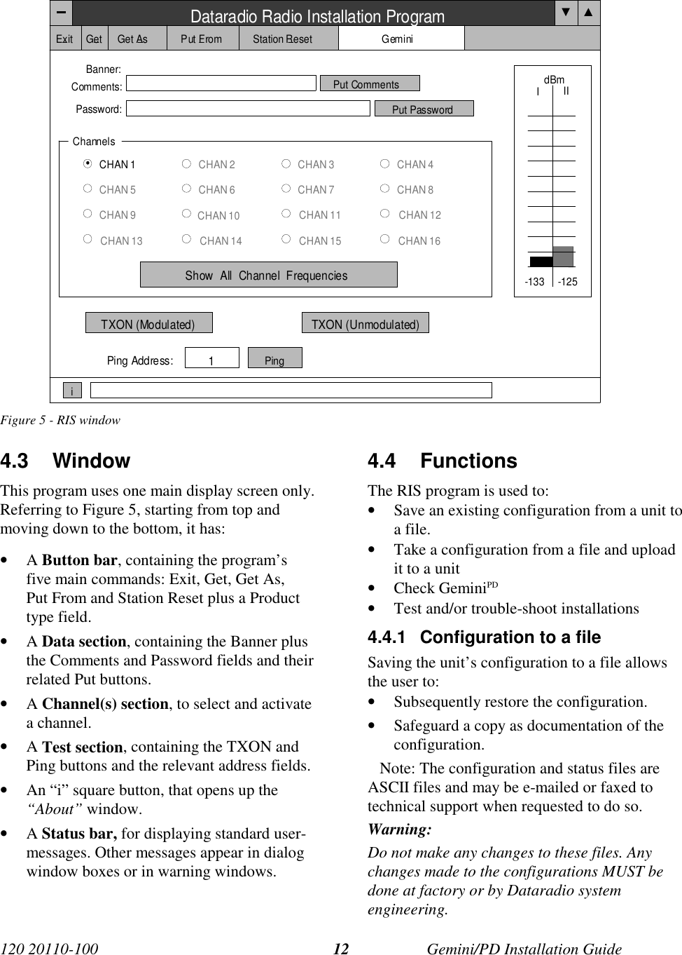
Installation Guide 1 01

GeminiPDMobile RadiomodemInstallation GuideVersion 1.10The entire contents of this manual and the Radio Installation Softwaredescribed in this manual are copyright 2000 by DATARADIO Inc.Copyright DATARADIO Inc.March 2000Part no.: 120 20110-110
Table of Contents1. PRODUCT OVERVIEW................................................................................................................................... 11.1 INTENDED AUDIENCE ....................................................................................................................................... 11.2 GENERAL DESCRIPTION .................................................................................................................................... 11.2.1 Features:................................................................................................................................................. 11.2.2 Configuration.......................................................................................................................................... 11.3 FACTORY TECHNICAL SUPPORT........................................................................................................................ 21.4 PRODUCT WARRANTY ...................................................................................................................................... 21.5 REPLACEMENT PARTS....................................................................................................................................... 21.5.1 Factory Repair........................................................................................................................................ 21.6 UNPACKING ...................................................................................................................................................... 22. INSTALLATION ............................................................................................................................................... 32.1 PLANNING THE INSTALLATION .......................................................................................................................... 32.1.1 Overview ................................................................................................................................................. 32.1.2 Location .................................................................................................................................................. 32.1.3 Cable Path............................................................................................................................................... 32.2 WARNINGS........................................................................................................................................................ 32.2.1 RF Radiation warning............................................................................................................................. 32.2.2 Interference with vehicular electronics................................................................................................... 32.2.3 Secure mounting...................................................................................................................................... 42.2.4 Explosive environments........................................................................................................................... 42.2.5 Installation in vehicles powered by liquefied gas. .................................................................................. 42.3 PHYSICAL UNIT................................................................................................................................................. 42.3.1 Recommended tools and supplies............................................................................................................ 42.3.2 Physical mounting of GeminiPD............................................................................................................... 42.4 ELECTRICAL INSTALLATION .............................................................................................................................. 52.4.1 Electrical requirements........................................................................................................................... 52.4.2 Routing of power cable ........................................................................................................................... 52.5 ANTENNA ......................................................................................................................................................... 72.5.1 Recommended tools and supplies............................................................................................................ 72.5.2 Planning.................................................................................................................................................. 72.5.3 Antenna Installation................................................................................................................................ 82.6 COMPLETING THE PHYSICAL INSTALLATION...................................................................................................... 82.7 CHECKING OUT NORMAL OPERATION................................................................................................................ 83. OPERATING DESCRIPTION ......................................................................................................................... 93.1 FRONT & REAR PANELS ................................................................................................................................... 93.2 DTE PORT INTERFACE ................................................................................................................................... 103.2.1 RS-232 Interface Signal Levels............................................................................................................. 104. RIS PROGRAM............................................................................................................................................... 114.1 OPERATION..................................................................................................................................................... 114.2 TO CONNECT AND START RIS ......................................................................................................................... 114.3 WINDOW......................................................................................................................................................... 124.4 FUNCTIONS ..................................................................................................................................................... 124.4.1 Configuration to a file........................................................................................................................... 124.4.1.1 “Get” button ..................................................................................................................................................134.4.1.2 “Get As” button.............................................................................................................................................134.4.2 Configuration from a File..................................................................................................................... 134.4.2.1 “Put From” button.........................................................................................................................................134.4.2.2 “Station Reset” button...................................................................................................................................134.4.3 Special Functions.................................................................................................................................. 14
 120 20110-100 ii GeminiPD Installation Guide4.4.3.1 Banner Field and “i” button ..........................................................................................................................144.4.3.2 Comments......................................................................................................................................................144.4.3.3 Password .......................................................................................................................................................144.4.4 Test Functions....................................................................................................................................... 154.4.4.1 Channel Selection..........................................................................................................................................154.4.4.2 RSSI Indicator...............................................................................................................................................154.4.4.3 TXON tests....................................................................................................................................................154.4.4.3.1 Unmodulated Carrier................................................................................................................................154.4.4.3.2 Modulated Carrier ....................................................................................................................................154.4.4.4 Ping Button ...................................................................................................................................................164.4.4.5 Ping addresses ...............................................................................................................................................165. TROUBLE-SHOOTING AND TESTING ..................................................................................................... 175.1 EQUIPMENT REQUIRED ................................................................................................................................... 175.2 BASIC TESTS................................................................................................................................................... 175.3 GPS TEST....................................................................................................................................................... 176. SPECIFICATIONS.......................................................................................................................................... 19FIGURE 1 - MOUNTING PLATE AND SLOT DIMENSIONS.................................................................................................... 5FIGURE 2 - BRACKET INSTALLATION.............................................................................................................................. 5FIGURE 3- DC POWER CONNECTOR............................................................................................................................... 6FIGURE 4 - FRONT AND REAR PANELS ............................................................................................................................ 9FIGURE 5 - RIS WINDOW.............................................................................................................................................. 12TABLE 1 - GEMINIPD LEDS INDICATIONS ..................................................................................................................... 10TABLE 2 - RS-232 SIGNAL LEVELS.............................................................................................................................. 10TABLE 3 - CARRIER MODULATION............................................................................................................................... 15TABLE 4 - TESTS, FULL & HALF CHANNEL UNITS ....................................................................................................... 18
 120 20110-100 iii GeminiPD Installation GuideWhat's New in Version 1.0HistoryMarch 2000Version 1.10 Addition of 800MHz specifications, revision to paragraph2.2.1 - RF Radiation Warning and to paragraphs 2.5 through 2.5.3. –Antenna installation.January 2000Version 1.0: First released version
 120 20110-100 iv GeminiPD Installation Guide Definitions The following terms are used throughout this document. Item Definition DCE Data Communications Equipment. This designation defines the direction (inputor output) of the various RS-232 interface signals. Modems are always wired asDCE. DTE Data Terminal Equipment. This designation defines the direction (input or out-put) of the various RS-232 interface signals. Most user equipment, as well asPCs, are wired as DTE. GCU GeminiPD Control Unit board GeminiPD High specs mobile radiomodem. PD = Parallel decode HDX Half Duplex. A unit that uses separate transmit and receive frequencies, butwhich may not transmit and receive simultaneously. RS-232 Industry–standard interface for data transfer.RIS Radio Installation Software. This software allows basic tests and unit configura-tion. Simplex A unit which uses the same frequency for transmit and receive.
120 20110-100 Gemini/PD Installation Guide11. PRODUCT OVERVIEWThis document provides the informationrequired for the installation, operation andverification of the DATARADIO GeminiPDmobile radiomodem.1.1 Intended AudienceThis document is designed for use by engi-neering design, installation, and mainte-nance personnel.1.2 General DescriptionGeminiPD is a mobile radiomodem aimed atthe public safety and public utility markets tomeet demand for high speed and highthroughput. It integrates all the necessaryhardware for data-only vehicular installationsup to but not including the laptop PC and itsapplication software.Example of applications are:1. Database inquiry systems.Small number of brief messages, (usu-ally from the mobile station) with fairlylong responses.2. Computer-aided dispatch (CAD).Large number of messages, (usuallyfrom the base station) with very briefresponses.3. Automatic Vehicle Location (AVL).Using built-in GPS receiver, determinesposition, speed and direction of fleetmembers.The  GeminiPD is made-up of a maintransceiver and an auxiliary receiver forParallel Decode (PD), a 40-Watt poweramplifier (35-Watt for 800 MHz model), aGemini Control Unit (GCU) with DSP drivenmodem and an integrated OEM GPSreceiver.1.2.1 Features:• One-piece integrated design in a ruggeddie-cast aluminum chassis.• Parallel Decode (PD) technology fea-turing dual receivers for added decodesensitivity in multi-path and fading en-vironments.• Sophisticated DSP-based modem designprovides added system performance,fewer retries and more effectivethroughput.• Automatic channel changing for im-proved roaming capabilities.• Built–in 16-channel synthesized radiotransceiver.• Power output of 10W to 40W (softwarecontrolled).• Data speeds of  9600  to  19200 b/s(9600 b/s maximum in half channels)• 3 available user ports using standardRS-232 interface• Half-duplex or simplex operation.• Built-in GPS receiver.• Out-of-band signaling enables transmis-sion of GPS reports with no effect onsystem performance.• Back-compatible with MobilPac/R1.2.2 ConfigurationGeminiPD is factory configured based oneach customer network system require-ments, usually by Dataradio System Engi-neering. Configuration is not changeable inthe field without notifying Dataradio.
120 20110-100 Gemini/PD Installation Guide21.3 Factory TechnicalSupport The Technical Support departments ofDATARADIO provide customer assistance ontechnical problems and serve as an interfacewith factory repair facilities.  They can bereached in the following ways: DATARADIO Inc. 5500 Royalmount Ave, suite 200 Town of Mount Royal Quebec, Canada H4P 1H7 Technical support hours: Monday to Friday9:00 AM to 5:00 PM, Eastern Time phone: +1 514 737-0020fax: +1 514 737-7883Email address: support@dataradio.com or  DATARADIO Corp. 6160 Peachtree Dunwoody RD., suite C-200 Atlanta, Georgia 30328 Technical support hours: Monday to Friday8:30 AM to 5:30 PM, Eastern Time phone: 1 770 392-0002 fax: 1 770 392-9199 Email address: drctech@dataradio.com1.4 Product Warranty Warranty information may be obtained bycontacting your sales representative.1.5 Replacement Parts This product is not field serviceable, exceptby the replacement of a complete unit. Spe-cialized equipment and training is requiredto repair the GCU board and radio modules. Contact Technical Support for service in-formation before returning equipment. ATechnical Support representative may sug-gest a solution eliminating the need to returnequipment.1.5.1 Factory Repair When returning equipment for repair, youmust request an RMA (Returned MaterialAuthorization) number. The Tech Supportrepresentative will ask you several questionsto clearly identify the problem. Please givethe representative the name of a contact per-son who is familiar with the problem,should questions arise during servicing ofthe unit. Customers are responsible for shippingcharges for returned units. Units in warrantywill be repaired free of charge unless thereis evidence of abuse or damage beyond theterms of the warranty. Units out of warrantywill be subject to service charges. Informa-tion about these charges is available fromTechnical Support.1.6 UnpackingWhen ready for installation, carefully un-pack your GeminiPD kit (p/n 023 6000-001)shipping carton and identify each item aslisted below:• One GeminiPD• Installation mounting bracket• Power cable – 22 feet (6.7 meters)• Small parts kitIf damage has occurred to the equipmentduring shipment, file a claim with the carrierimmediately.
120 20110-100 Gemini/PD Installation Guide32. Installation2.1 Planning theInstallation2.1.1 OverviewTo ensure trouble-free, efficient installation,start by inspecting the vehicle to determinethe optimum position for GeminiPD and itsantennas as well as the routing of all associ-ated cabling and wiring.2.1.2 LocationOften, installations in cars are done in thetrunk, underneath the back window ledge oron the trunk floor. In vans and small trucks,it is usually done in the back of the vehicle.In large vehicles, it is often done in the frontcabin.Be sure to place the GeminiPD unit in such away that:• The LEDs can be seen (as an aid introubleshooting)• Access to the antenna DE-9 connectorsis possible without removing the unit• Sufficient air may flow around the unitto provide adequate coolingGeminiPD is not fully waterproof, thereforeit should be mounted sufficiently away froman opened trunk lid or opened tailgate, win-dows or doors to avoid exposure to rainand/or snow. It also minimizes the chancethat material can be accidentally thrown onthe unit or of someone bumping against it.2.1.3 Cable PathTry to route the cables away from locationswhere they would be exposed to heat (ex-haust pipes, mufflers, tailpipes, etc.), batteryacid, sharp edges, mechanical damage orwhere they would be a nuisance to automo-bile mechanics, the driver or the passengers.Keep wiring away from automotive com-puter modules, other electronic modules andignition circuits to help prevent interferencebetween these components and radioequipment.Try using existing holes in firewall andtrunk wall and the channels above and be-low or beneath the doors, channels throughdoors and window columns that are con-venient to run cables and wires.Whenever possible, install conduit in whichto run the cables.2.2 WarningsBefore starting installation, review all of thefollowing warnings.2.2.1  RF Radiation warningThe Federal Communications Commission(FCC), with its action in the GeneralDocket, 79-144, March 13, 1985, hasadopted a safety standard for the human ex-posure to radio frequency electromagneticenergy emitted by FCC-regulated equip-ment. Only proper installation of the trans-ceiver antenna of GeminiPD as summarizedin paragraph 2.5 through 2.5.3 will result inuser exposure substantially below the FCCrecommended limits.Antennas installation must be done by quali-fied personnel. See paragraph 2.5 for rec-ommended antenna positioning.Transmissions when persons or animals out-side the vehicle are within two feet of theantenna may result in radio energy radiationburns or related injuries.2.2.2 Interference with vehicularelectronicsCertain vehicle electronic devices may beprone to malfunction due to lack of protec-tion from radio frequency energy presentwhen transmitting. It includes, and is not limited to:- Electronic fuel injection systems- Electronic anti-skid braking systems- Electronic cruise control systems
120 20110-100 Gemini/PD Installation Guide4If the installation vehicle contains suchequipment, consult the dealer for the makeof vehicle and enlist his aid in determiningif such electronic circuits will perform nor-mally when the radio is transmitting.2.2.3 Secure mountingFor vehicle occupant(s) safety, mountGeminiPD securely so that the unit will notbreak loose in case of an accident or violentmaneuvers.2.2.4 Explosive environmentsOperation of vehicular radio transmitters inexplosive environments may be hazardousand conventional safety precautions mustprevail. These include and are not limitedto:- Transmitting while fuelling the vehicle.Do not carry fuel containers in the samecompartment as GeminiPD.- Dynamite blasting caps may explodewhen transmitting radio operation takesplace within 500 feet. Always obey the“Turn Off Two-Way Radios” signsposted at sites where dynamite is beingused.If transporting blasting caps:a) Carry the blasting caps in an appropriatemetal container having a soft cushioninglining.b) Suppress transmissions whenever theblasting caps container is being loadedor unloaded into or from the vehicle.Check applicable local bylaws.2.2.5  Installation in vehiclespowered by liquefied gas.GeminiPD installations in vehicles poweredby liquefied petroleum gas with the LP-gascontainer in the trunk or other sealed-offspace within the interior of the vehicle mustconform to the National Fire Protection As-sociation Standard NFPA 58 which re-quires:- Space containing radio equipment shallbe isolated by a seal from the spacecontaining the LP-gas container and itsfittings.- Outside filling connections shall be usedfor the LP-gas container.The LP-gas container space shall be ventedto the outside of the vehicle.2.3 Physical Unit2.3.1  Recommended tools andsupplies• Electric drill for mounting holes• Hammer and center punch• Tie-wraps• Drills and circle cutters as needed ac-cording the size of screws (or nuts andbolts) used.• In-line “Power meter” capable of meas-uring forward and reflected power at theoperating frequency of the radio.2.3.2  Physical mounting ofGeminiPDStart by running all the cables (DC power,PC RS-232 as well as all antennas cabling)prior to mounting GeminiPD to assure thefeasibility of the planned cable routing. Besure to leave sufficient slack in each cableso the GeminiPD may be removed from themounting bracket for servicing with thepower applied and the antenna attached.GeminiPD is ready for installation.Cautions:• When drilling mountingholes, be careful to avoid dam-aging some vital part of the ve-hicle such as fuel tanks, trans-mission housing etc. Alwayscheck how far the mountingscrews extend below themounting surface prior to in-stallation.• Use of drill bit stops ishighly recommended.
120 20110-100 Gemini/PD Installation Guide5• After drilling, remove allmetal shavings before installingscrews.• Do not overtighten self-tapping screws.1. Once you have found a suitable mount-ing position for GeminiPD, hold the unitand the unattached mounting bracket inthe proposed mounting position andcheck that there is clearance behind theunit for the heatsink, cables, etc. Checkthat the position provides a large enoughflat surface that the bracket will not bedistorted when installed.Figure 1 - Mounting plate and slot dimensions2. Using the installation bracket as a tem-plate, mark the four locations for drill-ing (see Figure 1). Again, ensure thatdrilling at the selected points is safe andwill not cause damage.3. Indent the drilling positions with a cen-ter punch.4. Drill holes sized for the self-tappingscrews or for the nuts, bolts and lockwashers used.Caution: Slightly reduce the size of thedrilled holes when using self-tappingscrews in thin metal.Figure 2 - Bracket installation5. Install the bracket without distorting.6. Securely mount GeminiPD to the in-stalled bracket using the four supplied8x40 black machine screws.7. Drill any additional holes as requiredfor routing all cables and fit holes withsuitable grommets or bushingswhenever required.2.4  Electrical installation2.4.1 Electrical requirementsGeminiPD is designed to operate from a13.8Vdc nominal car battery (negativeground) and requires currents up to 15.0A. Itwill tolerate a supply voltage range of 10.9volts to 16.3 volts.In vehicles with a 24 VDC electrical system(mostly in trucks), it is essential to provide asuitably rated 24/12 VDC converter to iso-late the unit from the battery and protect itagainst excessive voltage.Warnings:Application of more than 16.3 VDCwill damage GeminiPD and is notcovered by the warranty.Always disconnect GeminiPD’s DCpower lead before connecting asecond battery, using power fromanother vehicle or power boosting(e.g. when “jump starting” the ve-hicle).2.4.2  Routing of power cable1. Start by disconnecting the vehicle’sbattery unless specifically prohibitedfrom doing so by the customer, vehiclemanufacturer, agent or supplier.Note:In this event, exercise ex-treme caution throughoutthe installation and fit thefuse only when the installa-tion is complete.2. The 22 feet (6.7 meters) long powercable consists of three wires attached to2.5"6.0"1.0"0.2"
120 20110-100 Gemini/PD Installation Guide6a Packard Electric “Weather-Pack” con-nector (DC power Connector).The DC Power connector has:• At position “A”, the smaller redswitch-sense wire (commonly to igni-tion)• At position “B”, the blue ground wire• At position “C”, a larger red B+ DCpower wire (MUST be unswitched)Figure 3- DC Power Connector3. Place this connector at GeminiPD’s radiopower input location. Do not connect atthis time. See paragraph 2.6 “Complet-ing physical installation”.4. Carefully route both the B and the Cwires to where the in-line fuse holderwill be installed, usually as close to thevehicle’s battery as practicable. Ensurethat leads do not chafe on any metalpart(s). Secure the wires at several lo-cations along their length.Caution:Use proper crimping tool.Common pliers are NOTacceptable.Warning:The DC Power lead must beunswitched5. Insert the negative (blue) lead into oneof the appropriate connector lug andcrimp solidly to force the metal contactsonto the wires.6. Repeat the step above for connecting thered DC power lead.7. Attach the negative wire at the batteryground and the positive lead at the bat-tery positive. Ensure tight and secureconnections.8. Fasten the fuse holder and leads.9. Carefully route the A wire to where theconnection will be made for switchsensing.• Connect to “Ignition” if you wish tohave GeminiPD turning ON and OFFdependent on the vehicle’s ignitionkey.• Connect to “Accessory” if you wishGeminiPD to be available when theengine is not running, but still de-pendent on the ignition key.• Connect to a user-supplied controlswitch.• In installations equipped with a“ChargeGuard”, connect to thecontrolled-side of the ChargeGuard(remembering that the DC Powerlead must NOT be switched).10. Make appropriate connections.Cautions:Where scraping to bare metal wasrequired, and at the battery postswhere wire ends and lugs may beexposed, apply anti-corrosion com-pound.Insert the fuse only when installa-tion is complete and ready to test.11. At the GeminiPD position, neatly coilcable slack and attach securely.ABCIGNITION(Small red wire)GROUND(Blue wire)13.8VDC B+ (Fused Red wire) SEAL(DO NOT REMOVE)ABCIGNITION(Small red wire)GROUND(Blue wire)13.8VDC B+ (Fused Red wire) SEAL(DO NOT REMOVE)
120 20110-100 Gemini/PD Installation Guide72.5 AntennaTo meet the FCC’s RF Exposure Guide-lines, the main transmitter antenna shouldbe installed to ensure a minimum distancebetween the body of the user or nearby per-sons and the antenna. To determine theminimum distance, calculate the antennagain less cable loss and refer to the graphbelow to identify the required minimumseparation distance.2.5.1  Recommended tools andsupplies• circle cutter• hole saw or• socket punch for antenna• Mini-UHF Crimp tool2.5.2 PlanningGeminiPD commonly uses three separate an-tennas:• Main transceiver – constraints are MPElimits and omni-directional factors• Auxiliary receiver – constraints are di-versity spacing and omni-directional re-quirements• GPS – constraints are TX spacing andclear sky view.For ground-plane dependent antennas –the center of metal surface is preferable forbest omni-directional pattern.For ground-plane independent antennas –installation may be close to the edges of thesurface.Follow spacing for TX antenna. Install theantennas in one of the following positions:- Most preferred for all antennas: center-line of roof. For transmitter antenna, itis the ONLY acceptable position.- Less preferred for receiver antenna:trunk lid, providing distance to trans-mitting antenna is respected whether lidis opened or closed.- Much less preferred, but permissible forreceiver antenna: left or right rear fend-ers, just in back of rear window- Least preferred, but permissible for re-ceiver antenna: left or right front fend-ers, ahead of windshieldNote: Proximity to other vehicle-mountedantennas may cause mutual inter-ference especially at higher fre-quencies.Max G(dB) vs distance to accomplish MPE limits -10-8-6-4-20246810207.93011.84015.75019.76023.67027.68031.59035.410039.4 distance to Tx antenna (cm/in)Overall gain  (dB)      (ant. gain -cable loss) 800 MHz400 MHz(UHF)
120 20110-100 Gemini/PD Installation Guide8The auxiliary receiver antenna must be in-stalled at least 5/8 λ distant from the trans-ceiver antenna.The GPS antenna placement requires afairly unobstructed view of the sky. It mustalso be at least two feet distant from thetransceiver antenna but it may be close tothe auxiliary RX antenna.For the optimum antenna spacing at the fre-quency you are using, consult system engi-neering.2.5.3 Antenna Installation1. Route good quality 50-ohm coaxial ca-bles (e.g. RG-223) from each of the se-lected antenna positions to the positionwhere the GeminiPD unit is mounted.2. Terminate the end at each of the antennapositions with the appropriate connectorfor the antenna used and make the con-nection.3. At the GeminiPD position, cut the threecables to length and terminate with theappropriate plug. For the transceiverand the auxiliary cables, use a Mini-UHF crimp plug using an appropriatecrimping tool. For the GPS, use a SMAconnector.4. Positively identify the transceiver mini-UHF plug and connect to the left rear ofGeminiPD.5. Positively identify the auxiliary receivermini-UHF plug and connect to the frontleft of GeminiPD to the RX position.6. Connect the SMA connector to the GPSposition below the auxiliary connectorposition.7. Do not skip this last step, trust us; it isan important one. To complete the in-stallation, tie-wrap together the auxil-iary and the GPS antenna cables at apoint about two inches in front of theunit. It will be much easier hereafter tocorrectly identify which mini-UHF pluggoes where. You DO NOT want to crossthe auxiliary plug with the transceiverplug.2.6  Completing the physicalInstallation.To complete the physical installation andprior to testing GeminiPD:• Connect DC Power cable’s connector toGeminiPD’s until you hear a click as thetwo parts snap together.• Re-check that all other connections aresecure (antennas, PC, etc.)• Switch vehicle ignition ON.You are now ready to check for normal op-eration and to run the Radio InstallationSoftware (RIS) program for testing or trou-ble-shooting.2.7  Checking out NormaloperationCheck that the vehicle ignition is ON.1- Check for proper operation of theGeminiPD’s LEDs as per Table 1 in sec-tion 3.1.2- Using the RIS program (described insection 4), and an in-line wattmeter,check forward & reverse power to con-firm main antenna installation.3- Using the RIS, check the RF link with abase station that can be heard by usingthe RIS “Ping” feature.See paragraph 4.4.4.4orIf user application and its base stationare available, test the installation bygoing through a normal sequence oftransmitting and receiving messages.
120 20110-100 Gemini/PD Installation Guide93. Operating Description3.1  Front & Rear PanelsThe front panel includes:• One mini-UHF type female antenna connector for the auxiliary receiver• One SMA type female connector for the GPS receiver• Two LED indicators• Three  DE-9F RS232 portsThe rear panel includes:• One mini-UHF type female antenna connector for the main transceiver• One 3-pin pigtailed DC Power connector with ignition senseFigure 4 - Front and rear panels®RX TXPWR PGM PC/SETUPDEV-1DEV-2DEV-3RXGPSGemini/PD6.000"2.000"
120 20110-100 Gemini/PD Installation Guide10Table 1 - GeminiPD LEDs indicationsGeminiPD LEDs indicationsPower-on Sequence (LEDs are paired) Normal Operation (LEDs are independent)PWR RX / TX Indication PWR Indication RX / TX IndicationRed Red Normal boot-up start(10 to 27 sec.) Green Normal ready state Off No network activityAmber Off Then 8 seconds tocompleting boot-upNormalGreen Off Normal stateAmber 1 Pulse/sec.Sufficient satellitesacquired by GPS Green Receiving packets“DBA sync” allowstransmitRed Off Hardware failure Amber Receiving packets“DBA out-of-sync”prevents transmitErrorsSlowRed/Green Red Software failure(firmware erased) Red TransmittingSpecialFastRed/Green Red Programming inprogress3.2  DTE Port InterfaceFor all three ports:DE-9 Fpin # Function1 DCD – from GeminiPD, normallyasserted2 RXD – data from GeminiPD3 TXD – data to GeminiPD4 DTR – to GeminiPD, handshaking5 Ground6 DSR – from GeminiPD, tied to VCCthrough current limiting resistor7 RTS - to GeminiPD, handshaking8 CTS – from GeminiPD, handshaking9 AUX auxiliary input to GeminiPD,“panic line” input (port 3):It may be activated by dry contactpull-up to the port’s DSR output. Itmay also tolerate user pull-up toexternal +12 VDC (car battery), butan isolated dry contact is preferreddue to the risk of noise-related falsealarms caused by the vehicle’selectrical system.We recommend the use of a shielded 9-wire ca-ble with all pins connected. These ports can beused for unit configuration, maintenance & ad-justment as well to connect user applications.3.2.1  RS-232 Interface Signal LevelsIn the descriptions of data signals, the followingconventions are used:Table 2 - RS-232 Signal LevelsTerm Alternates Signal levelON asserted, spacing +3 to +15 VOFF dropped, marking -3 to -15 V
120 20110-100 Gemini/PD Installation Guide114. RIS programThe Radio Installation Software (RIS) programis used to:• Check and troubleshoot GeminiPD.• Save an existing configuration.• Upload files for field-configuring units (Re-quires intervention with technical support).To run the program, you will need:- A PC or portable computer with a 486 classCPU or better.- 2 free megabytes of RAM.- A hard disk.- An available COM port.- A serial mouse, with its own driver installedis strongly recommend however most ac-tions can also be done using keyboardcommands.GeminiPD’s RIS program is available on diskette,Dataradio p/n 085 03322-00n. Please refer to thereadme.txt file included on the diskette forinstallation instructions.4.1 OperationThis support program is DOS-based and can berun in MS-Windows © MS-DOS mode.DO NOT have more than one copy of this pro-gram loaded at any given time in separate win-dows. Doing so creates COM port sharing con-flicts and failure to run the program alone re-sults in unexpected transmissions.It has the general look and feel of an MS-Windows program. Mouse operation is the con-ventional click, double-click plus click and dragmethod. Only left mouse button operation issupported.Any command or selection shown in gray is ei-ther unavailable or is awaiting another actionbefore activating.Help in the program is available at all points bypressing the F1 key. If a subject is highlighted,the help displayed will be context sensitive.Otherwise, the Index List is displayed.4.2  To connect and start RIS1- Connect a suitable 9-conductor straight RS-232 cable, between the unit’s front-mountedPC/Setup port and the RS-232 port of thePC or portable computer that will be run-ning Gemini.exe program.2- Check that GeminiPD is ON.3- To run the Radio Service Software (RIS):• In DOS, change to the directory where theprogram is installed and type gemini.exeand press ENTER.• In WIN 3.x, click on File, then on Run, typethe path or browse to select, click on OK torun gemini.exe.• In WIN 9x, click on Start, then on Run, typethe path or browse to select, click on OK torun gemini.exe.
120 20110-100 Gemini/PD Installation Guide12Figure 5 - RIS window4.3 WindowThis program uses one main display screen only.Referring to Figure 5, starting from top andmoving down to the bottom, it has:• A Button bar, containing the program’sfive main commands: Exit, Get, Get As,Put From and Station Reset plus a Producttype field.• A Data section, containing the Banner plusthe Comments and Password fields and theirrelated Put buttons.• A Channel(s) section, to select and activatea channel.• A Test section, containing the TXON andPing buttons and the relevant address fields.• An “i” square button, that opens up the“About” window.• A Status bar, for displaying standard user-messages. Other messages appear in dialogwindow boxes or in warning windows.4.4 FunctionsThe RIS program is used to:• Save an existing configuration from a unit toa file.• Take a configuration from a file and uploadit to a unit• Check GeminiPD• Test and/or trouble-shoot installations4.4.1  Configuration to a fileSaving the unit’s configuration to a file allowsthe user to:• Subsequently restore the configuration.• Safeguard a copy as documentation of theconfiguration.   Note: The configuration and status files areASCII files and may be e-mailed or faxed totechnical support when requested to do so.Warning:Do not make any changes to these files. Anychanges made to the configurations MUST bedone at factory or by Dataradio systemengineering.Dataradio Radio Installation ProgramExit Get Get As Put From Station Reset GeminiBanner:Comments:Password:Put CommentsPut PasswordChannelsCHAN 1CHAN 5CHAN 9CHAN 13CHAN 2CHAN 6CHAN 10CHAN 14CHAN 3CHAN 7CHAN 11CHAN 15CHAN 4CHAN 8CHAN 12CHAN 16Show  All  Channel  FrequenciesdBmIIITXON (Modulated) TXON (Unmodulated)Ping Address:1Pingi-133 -125
120 20110-100 Gemini/PD Installation Guide134.4.1.1 “Get” buttonOn the button bar, press the “Get” button to:• Establish linking• Download and automatically save the con-nected unit’s configuration setting to a filenamed with the unit' serial number: The RISstatus bar will then report “All parametersare successfully retrieved and saved in file[unit' s/n].GM2. Any previous configurationin the program is overwritten.• All test buttons and fields are now activated.If you do not wish to overwrite an existing con-figuration or prefer to name the file yourself,use the “Get As” button.4.4.1.2  “Get As” buttonOn the button bar, press the “Get As” button to:• Establish linking• Open the “File, Save As” window with theASCII file *.gm2 (already selected).• Save the connected unit’s operating charac-teristics (configuration setting) to a file, di-rectory or drive of your choice.The program will ask before overwriting anexisting file.• Status bar reports “All parameters are suc-cessfully retrieved and saved in [filename].• All buttons and fields are now activated.4.4.2  Configuration from a FileLoading a configuration from a file to a unit isuseful to:• Restore the operating characteristics of aunit (Requires intervention with technicalsupport.)• Carry out field updates using Dataradiosystem engineering supplied diskette(s).Warning:Do not make any changes tothese files. Any changes made tothe configurations MUST bedone at factory or by Dataradiosystem engineering.4.4.2.1  “Put From” button1- On the button bar, press the “Put From”button.2- In the opened “File, Put From” window,locate the drive, directory and file name ofthe relevant file.• This may be a configuration saved ear-lier from a unit.• It can also be from a Dataradio (factoryor system engineering) diskette.4- Select the appropriate file5- Press the “OK” button.• The status bar reports: “[filename] isdownloading into unit” and up to 30seconds later displays: “All parameters aresaved. Apply Station Reset to take effect!” .• All buttons and fields are now activated.6- Press the “Station Reset” button. See thenext paragraph for details.4.4.2.2  “Station Reset” buttonPress the Station Reset button as a last step afterdoing a “Put From”. The Station Reset buttoncauses downloaded parameters from a file ordiskette to take effect in the connected unit.Pressing Station Reset is not required after do-ing any Comments or Password configurationchange as these have their own Put Commentsand Put Password buttons.Station Reset does not break the connection.
120 20110-100 Gemini/PD Installation Guide144.4.3 Special FunctionsThe following RIS fields and buttons are used togather specific information concerning the con-nected unit:• Banner field• “i” button• Comments field and Put Comments button• Password and Put Password button4.4.3.1  Banner Field and “i” buttonThis field displays a string made up of the serialnumber of the connected unit followed by thefirmwares used and their version number.Format is:[serial number]:firmware 1 name, its version #,firmware 2 name, its version #.The serial number portion uniquely identifiesthe unit. It is a variable length, maximum eight-character alphabetic string assigned at the timeof manufacture. It is identical to the serial num-ber printed on the label of the unit. This numbercannot be changed and is used as part of the on-air protocol.Gemini/PD's firmwares resides in flash EPROMand are designed to allow field upgrades.When contacting your supplier, give the fullbanner string and the version of the RIS used.You will find the version number in the “About”window. To open it, click the lower left squarebutton (with a lowercase letter “i” in it).This field is blank prior to doing "Get", "Get As"or "Put From".4.4.3.2 Comments1- Type comments directly in the “Comments”field. These can be text up to 24 characters.Use this field to enter user-convenient de-scription(s) (customer name, location,etc…).2- Press the button “Put Comments” to makethe entry permanent. This field may be leftblank.On subsequent Get, Get As or Put From, thisfield displays entered comments. If no commentwas entered, the field will remain blank.4.4.3.3 PasswordThe password feature is useful where two (ormore) fleets share the same radio channel. Mo-biles without the proper password would stillreceive the message but the contents would notbe intelligible.1- Type your password directly in the “Pass-word” field. It is a string of 32 hexadecimalcharacters (exactly).2- Press the button “Put Password” to make theentry permanent. This field may be leftblank.On subsequent Get, Get As or Put From, thisfield will require that the correct password beentered. If none was entered, the field will re-main blank.Password information is NOT retrieved andsaved to a file, along with the configuration.Clearing a Password is done by entering 32 zeros.The Dataradio supplied password algorithm isdesigned to thwart the casual observer only. Itprovides a limited form of data privacy. There-fore, if your security requirements are high,Dataradio urges you to use external encryptiontechnology (such as Data Encryption Standard(DES)) in the Host and Mobiles computers.
120 20110-100 Gemini/PD Installation Guide154.4.4 Test FunctionsThe following RIS functions and buttons areused to carry out testing or trouble-shooting  ona connected unit:• Channels select• Show All Channel Frequencies• RSSI Indicator• TXON (Modulated)• TXON (Unmodulated)• Ping Address and Ping button4.4.4.1 Channel SelectionSelect the radio channel on which you wish tosend a test transmission by clicking the relevantavailable option button.The program automatically detects which ofsixteen channels are present on the connectedunit. For each factory-set channel available, therelevant round option button and channel num-ber is enabled (black). For each unavailablechannel, the round option button and channelnumber appears disabled (grayed-out). Only onechannel at a time may be selected.Pressing the “Show All Channel Frequencies”button opens a sub-window listing in tabularform the radio frequencies programmed for eachavailable channel(s).4.4.4.2 RSSI IndicatorThe Radio Signal Strength Indicator (RSSI) bargraph usually displays in twin-columns the rela-tive strength (in dBm) of an incoming RF signalon the selected channel.The left column indication, labeled "I", showsthe transceiver RX signal (rear mini-UHF con-nector).The right column indication, labeled "II", showsthe auxiliary RX signal (front mini-UHF con-nector).Meter precision is usually better than 3 dBm.This indicator functions as a single column"Power" (Watt) meter when pressing either ofthe test buttons: "TXON (Modulated)" or"TXON (Unmodulated)" with a range of 0 to 60watts.Precision is usually better than +/-3 watts.4.4.4.3 TXON tests4.4.4.3.1 Unmodulated CarrierUnmodulated carrier gives a clear carrier and isfrequently used for checking:• Frequency error• Forward and reverse powerPress the TXON (Unmodulated) button totransmit an unmodulated test signal on thechannel selected for 30 seconds or until pressedagain.The time remaining to test transmit is displayedon the status bar. The functions of all the otherbuttons are inoperative during test transmis-sions.Power check:1- Connect an in-line power meter between theradio and the antenna.2- Measure the forward (nominal 40W) andreflected power levels by powering TX ON.Never exceed 1W of reflected power.4.4.4.3.2 Modulated CarrierTest transmission generates a carrier modulatedwith 1kHz sinewave, at deviation level that de-pends on model and network speed:Table 3 - Carrier ModulationCarrier ModulationFull ChannelNetwork Speed Typical Deviation19200 ± 4.0 kHz16000 ± 4.0 kHz9600 ± 3.0 kHzHalf ChannelNetwork Speed Typical Deviation9600 ± 2.5 kHz
120 20110-100 Gemini/PD Installation Guide16This function is frequently used for checkingfrequency deviation.Press the TXON (Modulated) button to be-gin transmitting a modulated test signal onthe channel selected for 30 seconds or untilpressed again.The time remaining to test transmit is dis-played on the status bar.The functions of all the other buttons areinoperative during test transmissions.4.4.4.4 Ping ButtonThe Ping function checks connectivity by testingthe ability of Gemini to communicate with thebase station by sending a short transmissionquery and receiving a confirming response.1- Specify the channel (paragraph 4.4.4.1) andping address (paragraph 4.4.4.5)2- Press the Ping button to start ping testing.The time remaining to test transmit is dis-played on the status bar. The functions of allthe other buttons are inoperative duringpinging.The program sends a test query and continuestransmitting pings at brief intervals.As soon as a Ping test signal is returned fromthe address selected, the status bar displays:• “Ping Successful” and pinging stops.• If no ping signal is received after 60 sec-onds, ping testing stops and the status bardisplays “Ping Failed”.4.4.4.5 Ping addressesAddresses may be entered by typing directly inthe “Ping Address” field in two ways:1. Numerically, the valid address range is1-126.2. As an “Alpha-Mapped-Nibble”  (AMN) ad-dress, consisting of upper case letters in therange A-P. The valid address range is A toGN.The base address is usually: 1.The program may display one of the followingmessages on the status bar:“Ping address is not in AMN or number format” or“Ping address is not in the range A – GN”In either case, check that the address entered iswithin the acceptable range, is of a valid formatand correctly typed.
120 20110-100 Gemini/PD Installation Guide175. Trouble-Shooting andTestingThe checks described below should be done atannual intervals or whenever deterioration inperformance is noted.5.1 Equipment Required• 13.8 VDC (nominal) car battery, or13.8 VDC/20A regulated power supply (Inthe case the unit is not installed in a vehicle)• In-line watt meter (50W range)• Radio service monitor (IFR or equivalent).• Cable with mini-UHF male connector toconnect GeminiPD to the service monitor.5.2 Basic TestsRecommended checks:1. Transmit and Reverse power output2. Carrier frequency error3. Frequency deviation4. Receivers RSSI Check5. Link test between Gemini and the base sta-tion.6. GPS testRefer to Table 4 for checks 1 to 5.Important note: Before proceeding make surethat the service monitor has been calibratedrecently and has warmed up for at least thetime specified by its manufacturer.Some reported frequency and deviation prob-lems have actually been erroneous indicationsfrom service monitors that have not adequatelywarmed up. This is particularly likely when fieldservice is done during winter monthsRefer to the RIS section for function details5.3 GPS TestAbout three minutes after ignition is turned-on,the PWR LED on the GeminiPD front panelshould flash in amber color at the rate of onepulse per second. This indicates that the GPShas acquired the sky position of a sufficientnumber of satellites to arrive at a ground posi-tion solution.If the GPS has a good view of the sky and stillhas not generated any position solution withinthree minutes (it may take up to 10 minutes ormore if the sky view is partially blocked.), thefollowing trouble-shooting procedures should beundertaken to isolate the fault:1) Disconnect the GPS antenna cable connectorfrom the Gemini radio and check for + 5VDC on the center pin of the GPS antennaconnector on the radio using a Digital Volt-Meter (DVM). If the voltage is present, donot reconnect the cable and proceed to step 2.2) With the DVM, measure resistance betweenthe shell and the center conductor of the GPScable, resistance should be between 100 and300 Ohms, if it measures open or short cir-cuit the GPS antenna is either a passive an-tenna which is the WRONG type, or a defec-tive active antenna, replace with a knowngood active antenna.3) Connect the new antenna to Gemini and waitabout three minutes for the POSITIONACQUIRED indicator to start flashing onGeminiPD, if not, the Gemini radio or its GPSreceiver is defective
120 20110-100 Gemini/PD Installation Guide18Table 4 - Tests, Full & Half Channel UnitsCHECKLISTSTEP ACTION EXPECTED RESULTSat 25°°°°CMEASUREWITH IF NOT?Gemini units are set and characterized at the factory to optimize performances. It is not recommended totry to readjust the units.1Power-up LEDSequence as per Table 1 - GeminiPD LEDs indications2Connect and saveconfigPress RIS Get buttonas per section 4.4.13Main transceiverOutput PowerPress TX (Unmod)UHF: 40 watts+10%, -10%Factory-settable downto 10 watts as per cus-tomer request.Service monitorset to read poweror50W in-linewattmeterRefer to factory technical support.4Main transceiverReverse PowerPress TXON (Unmod)<1 W 50W in-linewattmeter check  for bad connections, dam-aged coax cable, etc.5Carrier FrequencyErrorPress TX (Unmod)±300 Hz Service monitorset to read fre-quency error Refer to factory technical support.4TX DeviationPress TXON (Modulated)   Carrier will be modu-lated with a 1 kHztone.Full channel unit19.2 and 16 kb/s:±4.0 kHz9.6 kb/s:±3.0 kHzHalf channel unit9.6 kb/s:±2.5 kHzTolerance is +5%, -10%for all bit rates.Service monitorset to readdeviation (IF filter set toMid or 30 kHzposition) Refer to factory technical support.5RF Link test"Ping" a base station “Ping Successful”as per sections4.4.4.4 Check on the RIS RSSI bar graphif the base station is within range(i.e. better than -107dBm)   orRefer to factory technical support.6 Set the service monitor to generate at the levels mentioned below. The carrier generated should be modu-lated with a 1.0 kHz tone at deviation of +/- 4.0kHz (full ch.) or +/-2.5kHz (half ch.).7Main ReceiverRSSI checks-70dBm-110dBm-120dBm- 70 dBm  +/-3-110  dBm +/-3-120 dBm +/- 3RIS bar graphRefer to factory technical support.The RSSI checks give a goodindication of receivers' health.8Aux Receiverrepeat as per step 7 same as step 7 RIS bar graph Refer to factory technical support.1 (unless you have set a lower value). Note that readings less than 40 watts may be due to losses in cables used for testing.Check also your wattmeter frequency calibration curve. Do not be too ready to condemn the transmitter.
120 20110-100 Gemini/PD Installation Guide196. SpecificationsGENERALUHF 800 MHzFrequency Tx 400 - 512 MHz1806 – 824 MHz (821-824)Frequency Rx 400 - 512 MHz 1851 – 869 MHz (866-869)Channel spacing 12.5, 20 or 25 kHzFrequency Control Digital Synthesizer / uControllerFrequency Stability 1.5 ppmOperating temperature -30°C to +60°C (25°C nominal) @ 95% non-cond. RHModes of Operation Simplex or Half DuplexNumber of channels 16 internally storedSupply voltage 13.6Vdc nominal (negative ground)10.9 – 16.3 VDCCircuit Protection 15 Amp fuse external2 & 4 Amp fuse internalRX Current at 13.6 VDC < 550 mA Standby (with auxiliary receiver)TX Current  at 13.6 VDC < 15 ATX/RX separation 5 MHz typicalNominal Dimensions 7.050” D x 6.000” W x 2.0000” HWeight: < 3.5 lbs.RF input/output Impedance 50 ohms nominalRF connector Main TX/RX: mini-UHF femaleAuxiliary RX: mini-UHF femaleGPS RX: SMA femaleInterface connector 3x DE-9F D-subminiatureRECEIVERSensitivity (12 dB SINAD) < 0.35 µV *Selectivity (25KHz) 75 dB typical70 dB minimumSelectivity (12.5) 65 dB typical60 dB minimumIntermodulation 75 dB typical70 dB minimumSpurious rejection 75 dB typical70 dB minimumFM hum & noise -45 dB typical *Conducted spurious < -57 dBm* psophometrically weighted filter                                                     1 WARNING: The frequency band 406 to 406.1 MHz is reserved for use by distress beaconsand should not be programmed into the unit.
120 20110-100 Gemini/PD Installation Guide20TRANSMITTERPower output UHF = 10-40 watts 800 MHz = 5-35 wattsDuty cycle 20% @ full power, 30 seconds maximum transmit timeConducted Spurious -75 dBc (-38 dBm @10 W) typicalFrequency stability 1.5 ppmFM hum and noise -45 dB max (25 kHz)Attack time < 10 msMODEM OPERATIONOperation Simplex/half duplexData rates 9600 b/s 19200 b/sModulation type DRCMSKPacket Error Rate(for < 1% error)better than –109 dBm at 19200 b/s full channel, single antennabetter than –112 dBm at 19200 b/s full channel, with P/DProtocol Dataradio ProprietaryDISPLAY and CONTROLS2 status LEDs RX/TX, PWRFCC / ICCERTIFICATIONSFCC IC (DOC)UHF EOTGPDA 773195525A800 MHz PENDING 773195643A

Navigation menu