CalAmp Wireless Networks GPDB Gemini User Manual updated
CALAMP WIRELESS NETWORKS INC. Gemini updated
Contents
- 1. preliminary version of user manual
- 2. Installation Guide 1 01
- 3. revised pages 7 and 8 for preliminary ver1 11
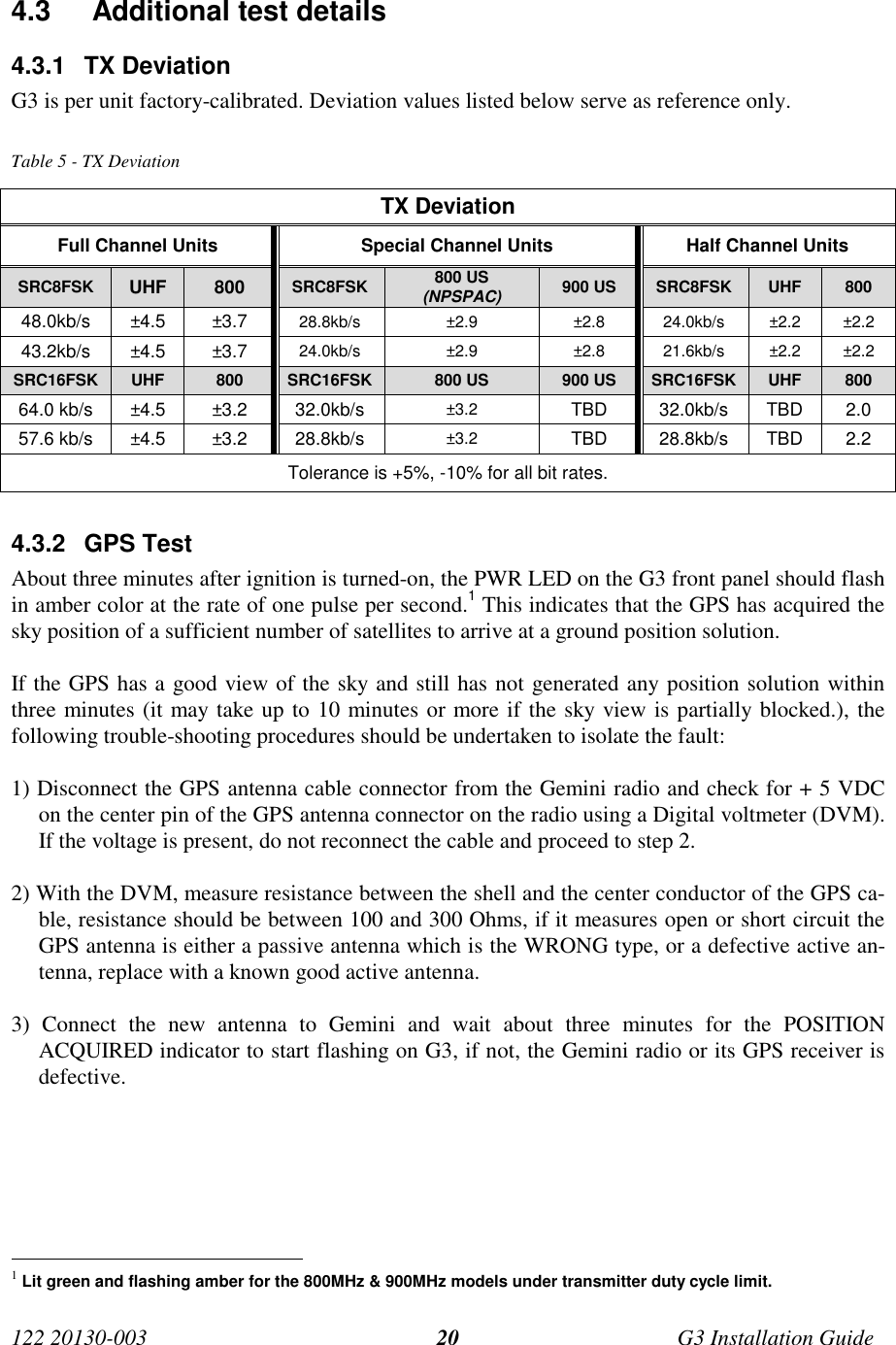
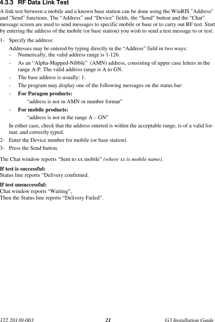
- 4. installation guide
- 5. Annex B Installation manual
- 6. Appendix A preliminary version 1 42
- 7. preliminary installation manual
- 8. preliminary version
- 9. preliminary updated user manual
- 10. preliminary version of updated installation manual
- 11. updated user manual
updated user manual