Cambium Networks XS35004 XS-3500 Wireless LAN Array User Manual xirrus
Xirrus, Inc. XS-3500 Wireless LAN Array xirrus
Contents
- 1. Users Manual Part 1
- 2. Users Manual Part 2
- 3. Users Manual Part 3
- 4. Users Manual Part 4
- 5. Users Manual Part 5
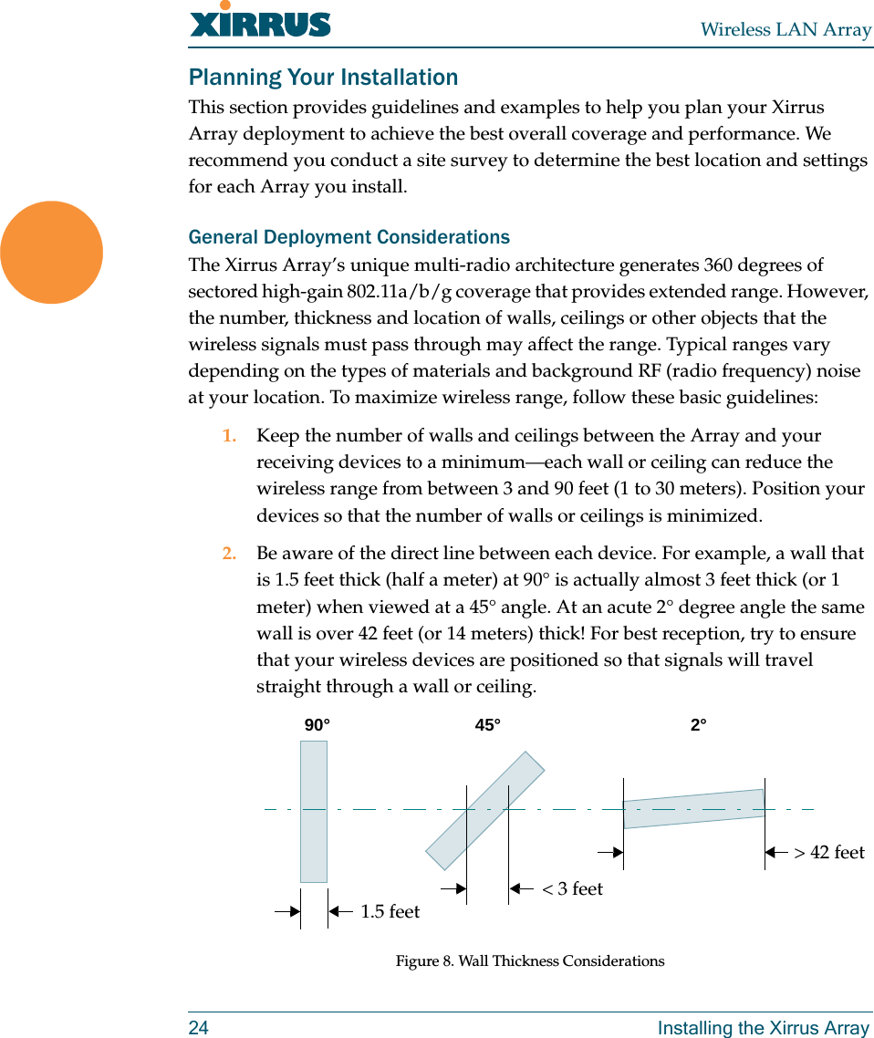
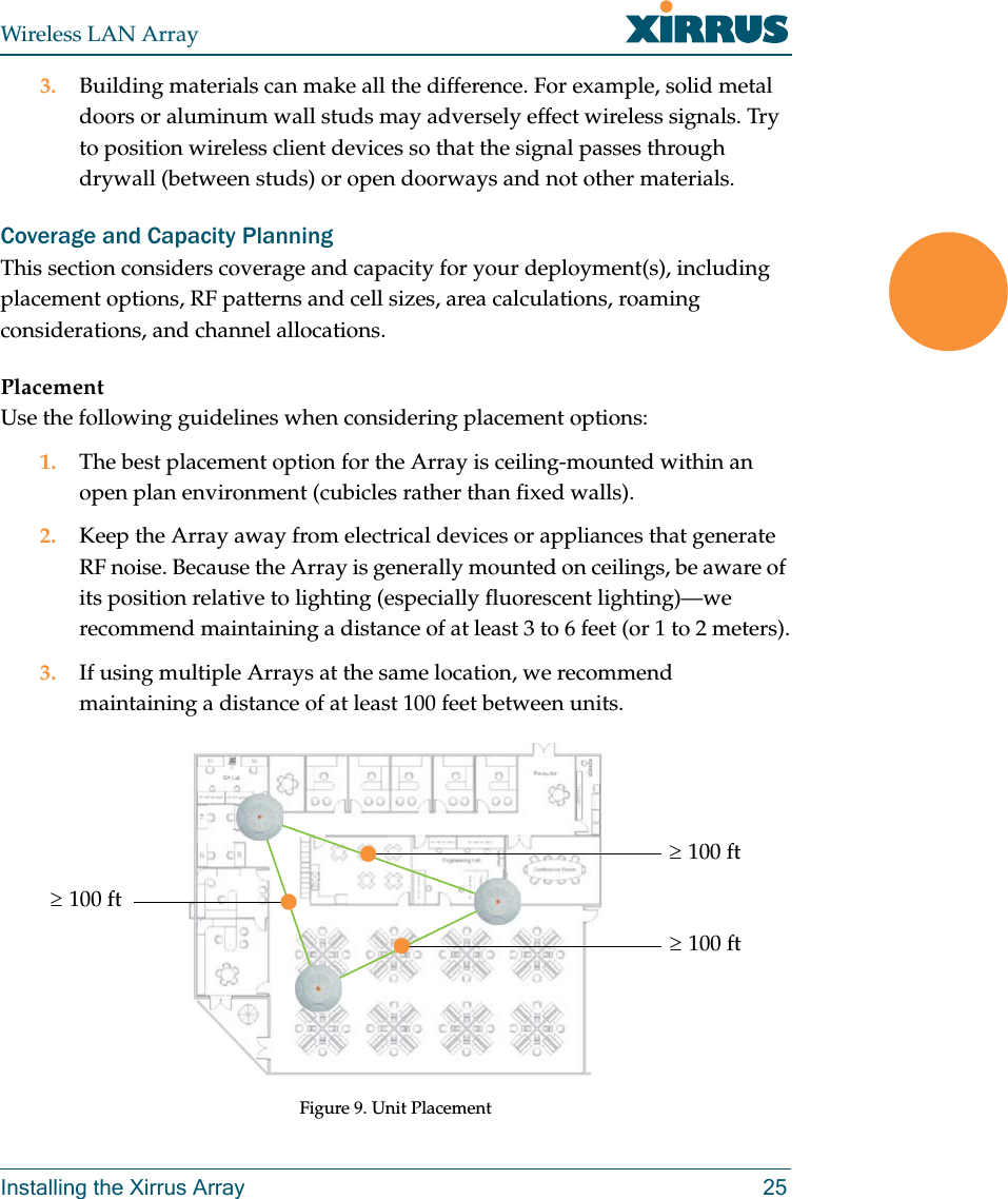
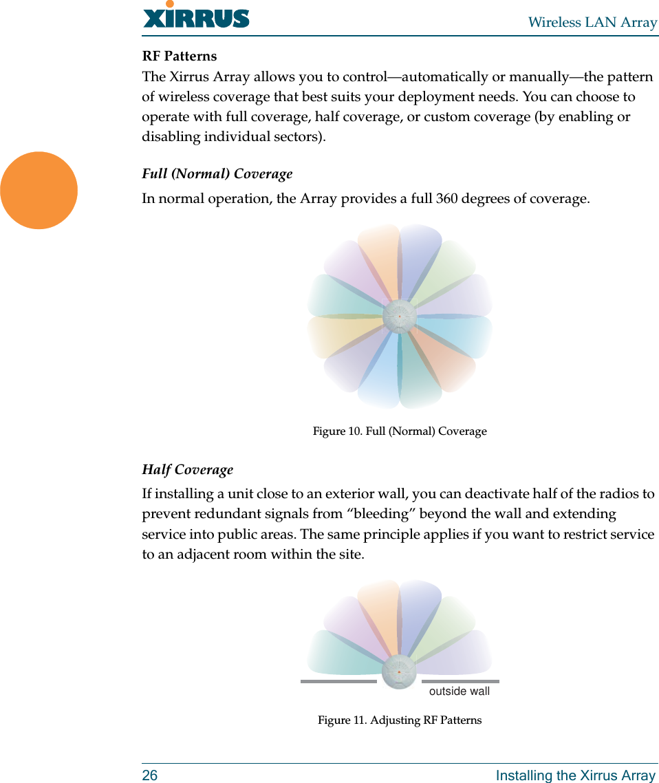
Users Manual Part 2