Cambium Networks XS35004 XS-3500 Wireless LAN Array User Manual xirrus
Xirrus, Inc. XS-3500 Wireless LAN Array xirrus
Contents
- 1. Users Manual Part 1
- 2. Users Manual Part 2
- 3. Users Manual Part 3
- 4. Users Manual Part 4
- 5. Users Manual Part 5
Users Manual Part 2

Wireless LAN Array
Introduction 19
Security Wireless Security:
WEP 40bit/128bit encryption
WPA with TKIP and AES encryption
Misappropriated APs automatically reset to
factory defaults (requires the Xirrus Wireless
Management System)
Rogue AP detection, with alerts and
classification
User and System Authentication:
WPA Pre-Shared Key authentication
Embedded RADIUS Server
802.1x EAP-TLS
802.1x EAP-TTLS
802.1x PEAP
External RADIUS servers
Authentication of Xirrus Arrays to the Xirrus
Management System (XM-3300)
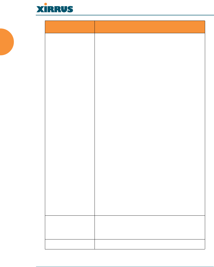
Element Specifications
Wireless LAN Array
20 Introduction
Wireless Number of Radios:
4 x 802.11a/b/g radios
Wireless Standards:
802.11a/b/g and g-only mode
802.11e (draft), 802.11i
Channel Selection:
Manual
Automatic
Frequency Bands:
11a: 5.15-5.25 GHz (UNII 1)
11a: 5.15-5.25 GHz (TELEC)
11a: 5.25-5.35 GHz (UNII 2)
11a: 5.470-5.725 (ETSI)
11a: 5.725-5825 GHz (UNII 3)
11b/g: 2.412-2.462 GHz (FCC)
11b/g: 2.412-2.472 GHz (ETSI)
11b/g: 2.412-2.484 GHz (TELEC)
Antenna:
4 internal 3 dBi 180° 802.11b/g sectorized
antennas
1 internal 2 dBi 360° omni-directional antenna
External RP-TNC connector
Radio Approvals:
FCC (United States)
EN 301.893 (Europe)
Compliance UL / cUL 60950 and EN 60950
FCC Part 15.107 and 15109, Class A
EN 301.489 (Europe)
Warranty One year (hardware), 90 day (software)
Element Specifications

Wireless LAN Array
Installing the Xirrus Array 21
Installing the Xirrus Array
This chapter defines the prerequisites for installing the Xirrus Array and provides
instructions to help you complete a successful installation. Section headings for
this chapter include:
z“Installation Prerequisites” on page 21
z“Planning Your Installation” on page 24
z“Installation Workflow” on page 39
z“Unpacking the Xirrus Array” on page 40
z“Installing Your Xirrus Wireless LAN Array” on page 41
z“Powering Up the Xirrus Wireless LAN Array” on page 51
z“Establishing Communication with the Array” on page 53
z“Performing the Express Setup Procedure” on page 54
Installation Prerequisites
Your Xirrus Array deployment requires the presence of hardware and services in
the host wired/wireless network, including:
zDedicated AC power outlet
Unless you are using the Xirrus Remote DC Power System (XP-3100) with
the DC version of the Xirrus Array, you need a dedicated power outlet to
supply AC power to each unit deployed at the site. If you are using the
optional XP-3100, then DC power is supplied to all units and only one AC
outlet is required for the XP-3100.
zEthernet port (read notes)
You need at least one 10/100/1000 BaseT port to establish wired Gigabit
Ethernet connectivity (via the product’s Gigabit 1 or Gigabit 2 port) and
one 10/100 BaseT port (if desired) for product management.
!The Array’s Ethernet ports should be plugged into an Ethernet
switch, not an Ethernet hub—if a hub is used, we recommend that
you connect only one Ethernet port.
Wireless LAN Array
22 Installing the Xirrus Array
zSecure Shell (SSH) utility
To establish secure remote command line access to the Array, you need a
Secure Shell (SSH) utility, such as PuTTY.
zSecure Web browser
Either Internet Explorer (version 6.0 or higher), Netscape Navigator
(version 7.0 or higher), or Mozilla Firefox (version 1.01 or higher) and it
must be available on the same subnet as the Array. A secure Web browser
is required for Web-based management of the Array.
zSerial connection capability
To connect directly to the console port on the Array, your computer must
be equipped with a male 9-pin serial port and terminal emulation
software (for example, HyperTerminal).
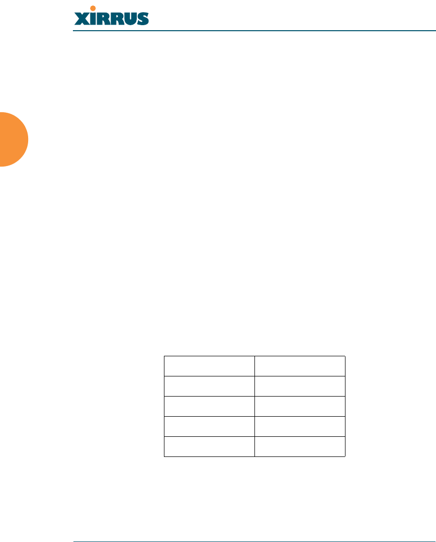
Use the following settings when establishing a serial connection:
!The Gigabit1 Ethernet interface is the primary port for both data
and management traffic. If a single Ethernet connection is used, it
must be connected to the Gigabit1 Ethernet interface.
The 10/100 Ethernet Port can be used for managing the Array, and
will only bridge management traffic. See also, “Port Failover
Protection” on page 33.
Bits per second 115,200
Data bits 8
Parity None
Stop bits 1
Flow control None

Wireless LAN Array
Installing the Xirrus Array 23
Optional Network Components
The following network components are optional.
zDHCP server
To distribute IP addresses and ancillary information to your Xirrus Array.
zXirrus Wireless Management System (XM-3300)
The optional XM-3300 offers powerful management features for small or
large Xirrus Array deployments.
zXirrus Remote DC Power System (XP-3100)
The optional XP-3100 provides distributed DC power to multiple Arrays,
eliminating the need to run dedicated AC power to each unit and
facilitating backup power when connected via a UPS.
zExternal RADIUS server
Although your Array comes with an embedded RADIUS server, for
802.1x authentication in large deployments you may want to add an
external RADIUS server.
Client Requirements
The Xirrus Array should only be used with Wi-Fi certified client devices.
Wireless LAN Array
24 Installing the Xirrus Array
Planning Your Installation
This section provides guidelines and examples to help you plan your Xirrus
Array deployment to achieve the best overall coverage and performance. We
recommend you conduct a site survey to determine the best location and settings
for each Array you install.
General Deployment Considerations
The Xirrus Array’s unique multi-radio architecture generates 360 degrees of
sectored high-gain 802.11a/b/g coverage that provides extended range. However,
the number, thickness and location of walls, ceilings or other objects that the
wireless signals must pass through may affect the range. Typical ranges vary
depending on the types of materials and background RF (radio frequency) noise
at your location. To maximize wireless range, follow these basic guidelines:
1. Keep the number of walls and ceilings between the Array and your
receiving devices to a minimum—each wall or ceiling can reduce the
wireless range from between 3 and 90 feet (1 to 30 meters). Position your
devices so that the number of walls or ceilings is minimized.
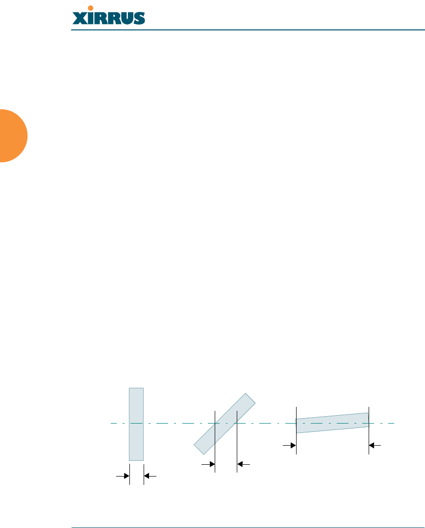
2. Be aware of the direct line between each device. For example, a wall that
is 1.5 feet thick (half a meter) at 90° is actually almost 3 feet thick (or 1
meter) when viewed at a 45° angle. At an acute 2° degree angle the same
wall is over 42 feet (or 14 meters) thick! For best reception, try to ensure
that your wireless devices are positioned so that signals will travel
straight through a wall or ceiling.
Figure 8. Wall Thickness Considerations
90° 45°
1.5 feet
< 3 feet
> 42 feet
2°
Wireless LAN Array
Installing the Xirrus Array 25
3. Building materials can make all the difference. For example, solid metal
doors or aluminum wall studs may adversely effect wireless signals. Try
to position wireless client devices so that the signal passes through
drywall (between studs) or open doorways and not other materials.
Coverage and Capacity Planning
This section considers coverage and capacity for your deployment(s), including
placement options, RF patterns and cell sizes, area calculations, roaming
considerations, and channel allocations.
Placement
Use the following guidelines when considering placement options:
1. The best placement option for the Array is ceiling-mounted within an
open plan environment (cubicles rather than fixed walls).
2. Keep the Array away from electrical devices or appliances that generate
RF noise. Because the Array is generally mounted on ceilings, be aware of
its position relative to lighting (especially fluorescent lighting)—we
recommend maintaining a distance of at least 3 to 6 feet (or 1 to 2 meters).
3. If using multiple Arrays at the same location, we recommend
maintaining a distance of at least 100 feet between units.
Figure 9. Unit Placement
≥ 100 ft
≥ 100 ft
≥ 100 ft
Wireless LAN Array
26 Installing the Xirrus Array
RF Patterns
The Xirrus Array allows you to control—automatically or manually—the pattern
of wireless coverage that best suits your deployment needs. You can choose to
operate with full coverage, half coverage, or custom coverage (by enabling or
disabling individual sectors).
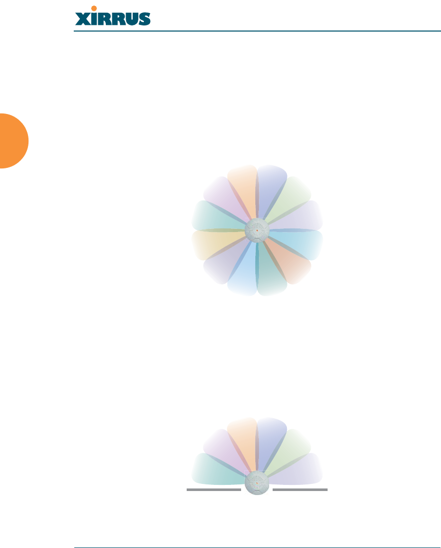
Full (Normal) Coverage
In normal operation, the Array provides a full 360 degrees of coverage.
Figure 10. Full (Normal) Coverage
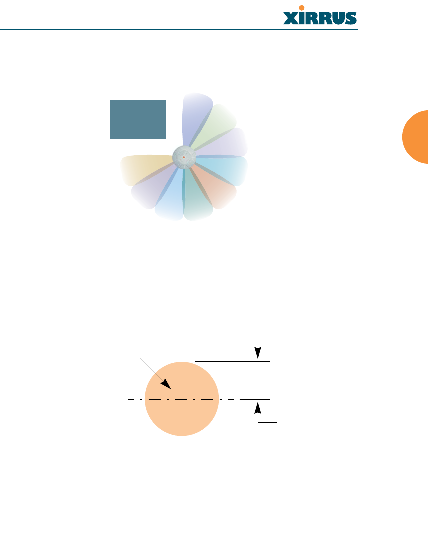
Half Coverage
If installing a unit close to an exterior wall, you can deactivate half of the radios to
prevent redundant signals from “bleeding” beyond the wall and extending
service into public areas. The same principle applies if you want to restrict service
to an adjacent room within the site.
Figure 11. Adjusting RF Patterns
outside wall
Wireless LAN Array
Installing the Xirrus Array 27
Custom Coverage
Where there are highly reflective objects in close proximity to the Array, you can
turn off specific radios to avoid interference and feedback.
Figure 12. Custom Coverage
Calculating Areas
Before we discuss cell sizes, it is useful to know how to calculate the area of a
circle (because the Array radiates a full 360 degrees). The area of a circle is equal
to pi (π) times the square of the radius, where pi is equal to 3.14. The following
graphic calculates the area of a circle with a radius of 20 feet.
Figure 13. Calculating the Area of a Circle
object
reflective
20 ft
3.14 x 202 = 1,256 sq ft
Wireless LAN Array
28 Installing the Xirrus Array
Capacity and Cell Sizes
Cell sizes should be calculated based on the number of users, the applications
being used (for example, data/video/voice), and the number of Arrays available
at the location. The capacity of a cell is defined as the minimum data rate desired
for each sector multiplied by the total number of sectors being used.
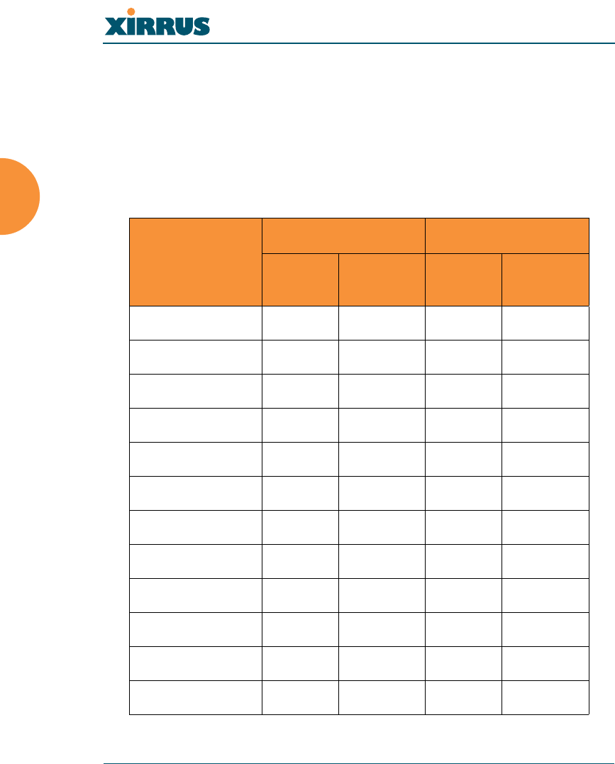
The following chart shows the maximum recommended cell sizes for each data
rate.
Desired
Data Rate
(Mbps)
11a Cell Size 11b/g Cell Size
Radius
(feet)
Area
(sq. feet)
Radius
(feet)
Area
(sq. feet)
54 100 31,400 104 33,962
48 185 107,466 183 105,155
36 247 191,568 260 212,264
24 278 242,672 283 251,479
18 309 299,810 338 358,726
12 339 360,852 364 416,037
9 371 432,193 374 439,211
6 402 507,437 390 477,594
11 0 0 416 543,396
5.5 0 0 437 649,295
2 0 0 458 658,659
1 0 0 468 687,735
Wireless LAN Array
Installing the Xirrus Array 29
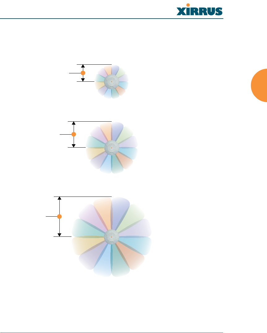
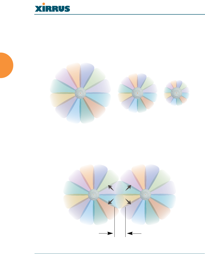
Sample 802.11a Cells
The following 802.11a sample cells illustrate the coverage area and minimum
throughput you can expect (per sector) based on the size of each cell. Notice how
the throughput increases as the cell size decreases, and vice versa.
Figure 14. Sample 802.11a Cells
68 ft
98 ft
165 ft
54 Mbps per sector
36 Mbps per sector
18 Mbps per sector
14,520 sq ft
30,157 sq ft
85,487 sq ft
Wireless LAN Array
30 Installing the Xirrus Array
Fine Tuning Cell Sizes
Adjusting the transmit power allows you to fine tune cell sizes. There are three
settings—Large, Medium, or Small (the default is Large). If you are installing
many units in close proximity to each other, reduce the transmit power to avoid
excessive interference with other Arrays or installed APs. See also, “IAP Settings”
on page 90.
Figure 15. Transmit Power
Roaming Considerations
Cells should overlap approximately 10 - 15% to accommodate client roaming.
Figure 16. Overlapping Cells
Large
Medium
Small
ROAMING
10 - 15% overlap

Wireless LAN Array
Installing the Xirrus Array 31
Allocating Channels
Because the Xirrus Array is a multi-channel device, allocating the best channels to
radios is important if peak performance is to be maintained.
Automatic Channel Selection
We recommend that you allow the Array to make intelligent channel allocation
decisions automatically. In the automatic mode, channels are allocated
dynamically, driven by changes in the environment.
Manual Channel Selection
You can manually assign channels on a per radio basis, though manual selection
is not recommended (and not necessary).
Figure 17. Allocating Channels Manually
#To avoid co-channel interference, do not select adjacent channels for radios that
are physically next to each other.
Maintain channel separation
Wireless LAN Array
32 Installing the Xirrus Array
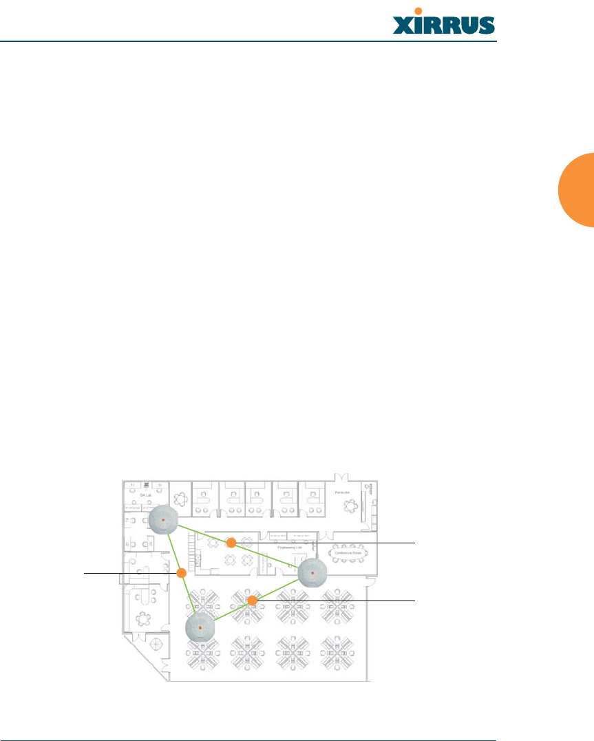
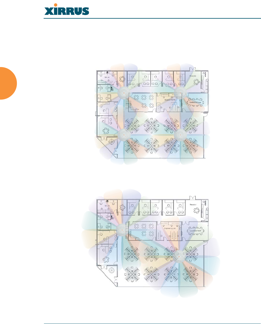
Deployment Examples
The following examples employ 802.11a cells, each offering minimum
throughputs of 54 Mbps, 36 Mbps, and 18 Mbps per sector respectively, and
assume a floor plan covering a total area of about 60,000 square feet.
Figure 18. Deployment Scenario (54 Mbps)—Per Sector
Figure 19. Deployment Scenario (36 Mbps)—Per Sector
Wireless LAN Array
Installing the Xirrus Array 33
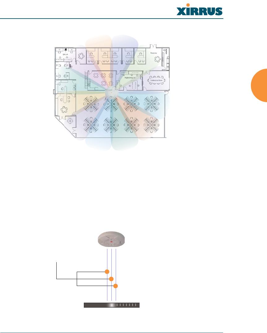
Figure 20. Deployment Scenario (18 Mbps)—Per Sector
Failover Planning
This section discusses failover protection at the unit and port levels.
Port Failover Protection
To ensure that service is continued in the event of a port failure, you can utilize
the Gigabit 1 and Gigabit 2 ports simultaneously.
Figure 21. Port Failover Protection
Ethernet switch
Multiple port connections
Wireless LAN Array
34 Installing the Xirrus Array
In addition, the Array has full failover protection between the Gigabit 1 and
Gigabit 2 Ethernet ports (see following table).
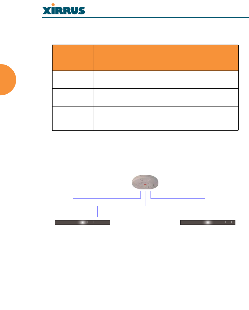
Switch Failover Protection
To ensure that service is continued in the event of a switch failure, you can
connect Arrays to more than one Ethernet switch (not a hub).
Figure 22. Switch Failover Protection
Interface Bridges
data?
Bridges
mgmt
traffic?
Fails over
to: IP address
Fast Ethernet No Yes None DHCP or
static
Gigabit 1 Yes Yes Gigabit 2 DHCP or
static
Gigabit 2 Yes Yes Gigabit 1 Assumes the
IP address of
Gigabit 1
#Gigabit Ethernet connections must be on the same subnet.
Ethernet switch Backup switch
Ethernet connections

Wireless LAN Array
Installing the Xirrus Array 35
Power Planning
This section discusses the AC and DC power options.
AC Power
The AC power option requires a direct connection between the Array and a
dedicated AC power outlet. The power cord is provided with the unit.
Remote Distributed DC Power
To deliver DC power to the Array, you must have the optional Xirrus Remote DC
Power System (XP-3100) and a Xirrus Array that supports DC power—see
Figure 4 on page 8 . The XP-3100 provides DC power to multiple Arrays from a
single source, and requires only one AC power outlet.
Depending on the type of cable used, Arrays can be located up to 1,000 feet from
the XP-3100. In addition, the XP-3100 can be plugged into a UPS to prevent power
failure to all Arrays in the network.
Security Planning
This section offers some useful guidelines for defining your preferred encryption
and authentication method. For additional information, go to the Security section
of “Frequently Asked Questions” on page 222.
Wireless Encryption
Encryption ensures that no user can decipher another user’s data transmitted
over the airwaves. There are three encryption options available to you, including:
zWEP-40bit or WEP-128bit
Because WEP is vulnerable to cracks, we recommend that you only use
this for legacy devices that cannot support a stronger encryption type.
zWi-Fi Protected Access
This is much more secure than WEP and uses TKIP for encryption.
#When using CAT5 cable, DC power can be provided up to a distance of 300
feet.

Wireless LAN Array
36 Installing the Xirrus Array
zWi-Fi Protected Access with AES
This is government-grade encryption—available on most new client
adapters—and uses the AES–CCM encryption mode (Advanced
Encryption Standard–Counter Mode).
Authentication
Authentication ensures users are who they say they are, and occurs when users
attempt to join the wireless network and periodically there after. The following
authentication methods are available with the XS-3900:
zRADIUS 802.1x
802.1x uses a remote RADIUS server to authenticate large numbers of
clients, and can handle different authentication methods (EAP-TLS, EAP-
TTLS EAP-PEAP).
zXirrus internal RADIUS server
Includes all the core functionality of a full RADIUS server built into the
Xirrus Array. Recommended for smaller numbers of users (about 100 or
less).
zPre-Shared Key
Uses a pass-phrase or key that is manually distributed to all authorized
users. The same passphrase is given to client devices and entered into
each Array.
zMAC Access Control Lists (ACLs)
MAC access control lists provide a list of client adapter MAC addresses
that are allowed or denied access to the wireless network, and can be
used in addition to any of the above authentication methods. ACLs are
good for embedded devices, like printers and bar-code scanners (though
MAC addresses can be spoofed). The Xirrus Array supports 512 ACL
entries.

Wireless LAN Array
Installing the Xirrus Array 37
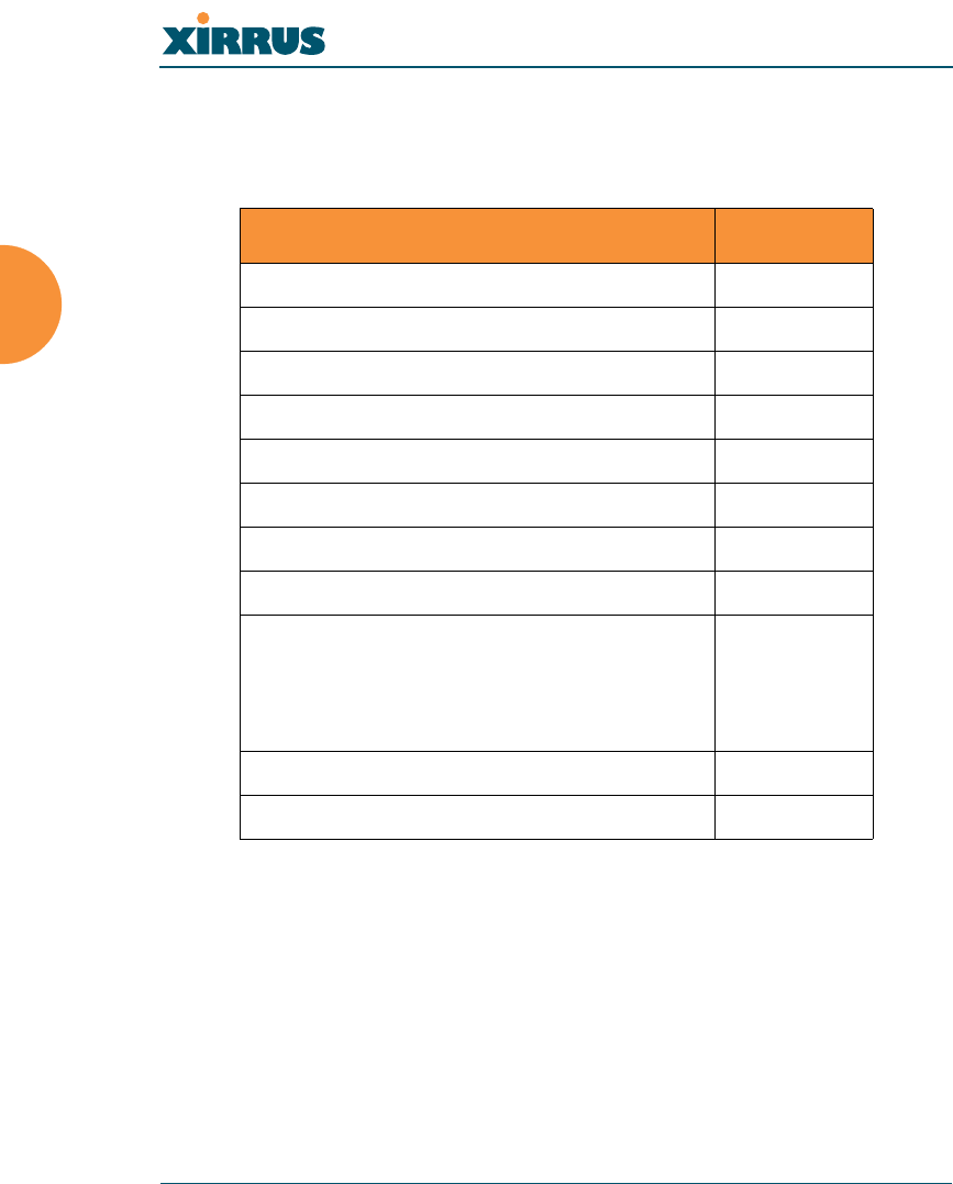
Network Management Planning
Network management can be performed using any of the following methods:
zCommand Line Interface, using an SSH (Secure Shell) utility, like PuTTY.
zWeb-based management, using the Array’s embedded Web Management
Interface (WMI). This method provides configuration and basic
monitoring tools, and is good for small deployments (one or two units).
zWeb-based management, using the optional Xirrus Wireless Management
System (XM-3300). The XM-3300 is used for managing large Array
deployments from a centralized Web-based interface and offers the
following features:
Layer 3 appliance
Globally manage large numbers of Arrays
Seamless view of the entire wireless network
Easily configure large numbers of Arrays
Rogue AP monitoring
Easily manage system-wide firmware updates
Monitor performance and trends
Aggregation of alerts and alarms
Wireless LAN Array
38 Installing the Xirrus Array
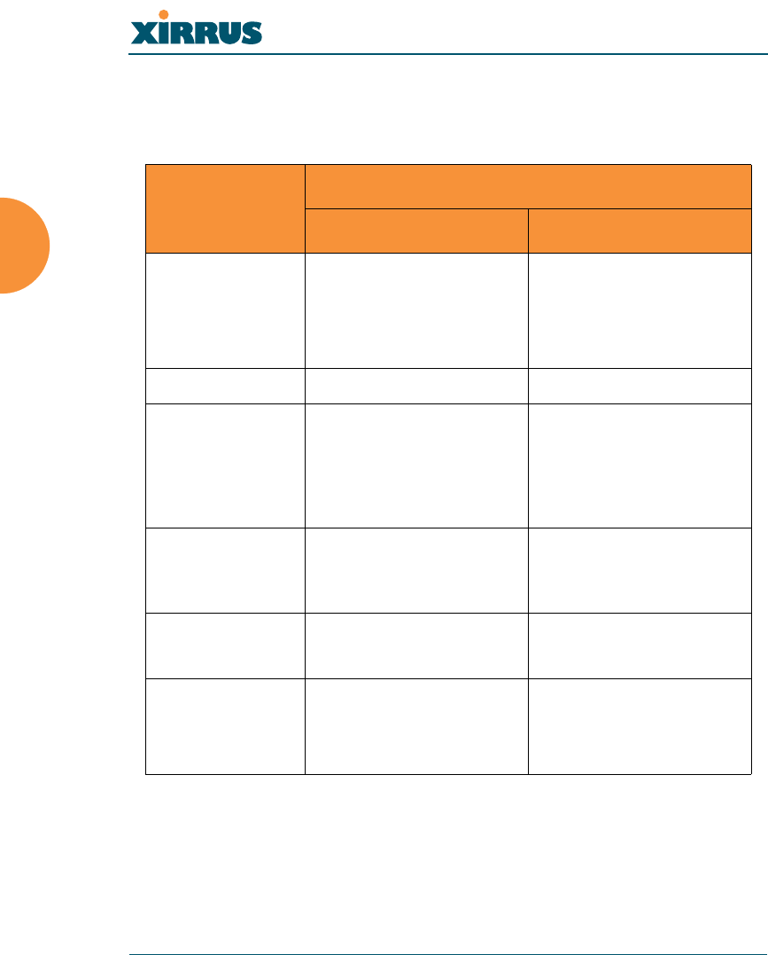
Deployment Summary
The following table summarizes your deployment options for small and large
deployments.
Function
Number of Xirrus Arrays
One or Two Three or More
Power AC
DC (with XP-3100)
AC
DC (with XP-3100)
UPS backup
(recommended)
Failover Recommended Highly recommended
VLANs Optional Optional use,
Can be used to put all
APs on one VLAN or
map to existing VLAN
scheme
Encryption WPA with TKIP
(recommended)
PSK or 802.1x
WPA with AES
(recommended)
802.1x keying
Authentication Internal RADIUS server
Pre-Shared Key
External RADIUS server
Management Internal WMI
Internal CLI
XM-3300
XM-3300
Wireless LAN Array
Installing the Xirrus Array 39
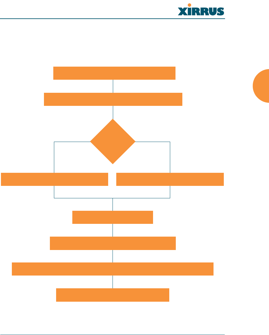
Installation Workflow
This workflow illustrates the steps that are required to install and configure your
Xirrus Array successfully. Review this flowchart before attempting to install the
unit on a customer’s network.
Figure 23. Installation Workflow
Determine the number of Arrays needed
Choose the location(s) for your Xirrus Arrays
AC DC
Install the mounting plate
Connect the cables and turn on the power
Verify that the Ethernet link and radio LEDs are functioning correctly
Perform the Express Setup procedure
Run AC power and Ethernet cables Run DC power and Ethernet cables
AC or DC
power?
Wireless LAN Array
40 Installing the Xirrus Array
Unpacking the Xirrus Array
When you unpack your Xirrus Array, you will find the following items in the
carton:
Item Quantity
Xirrus Wireless LAN Array 1
AC power cord 1
Console cable 1
Mounting plate 1
Mounting screws 4
Tile grid mounting clamps 4
Clamp nuts 4
Mounting template 1
CD-ROM containing:
This User’s Guide in PDF format
End User License Agreement (EULA)
README file
1
Quick Install Guide 1
Registration Card 1
Wireless LAN Array
Installing the Xirrus Array 41
Installing Your Xirrus Wireless LAN Array
This section provides instructions for installing your Xirrus Wireless LAN Array.
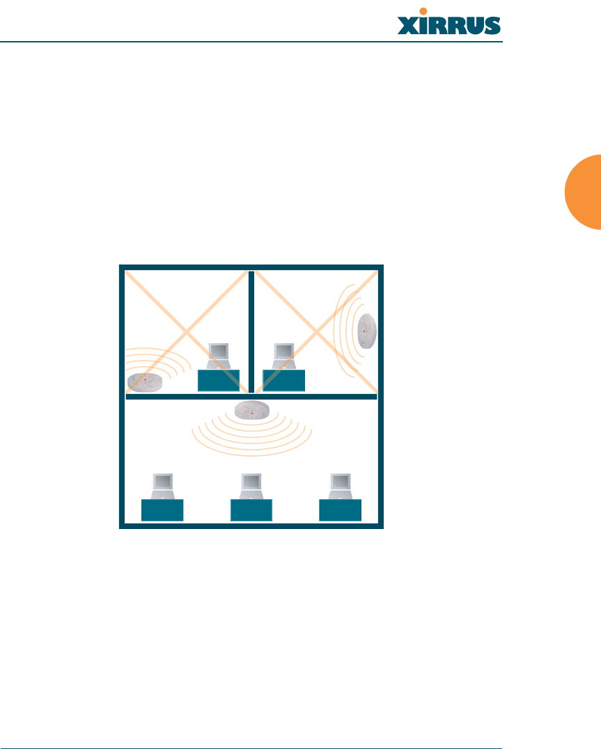
Choosing a Location
Based on coverage, capacity and deployment examples discussed earlier in this
chapter, choose a location for the Array that will provide the best results for your
needs. The Xirrus Array was designed to be mounted on a ceiling where the unit
is unobtrusive and wireless transmissions can travel unimpeded throughout open
plan areas. Choose a location that is central to your users (see the following
diagram for correct placement.
Figure 24. Array Placement
WR
ONG
CORRECT
R
ORRE
R
ORREC
WR
ONG
G
G
O
ON
R
O
R
ON
ON
R
O
R
ON

Wireless LAN Array
42 Installing the Xirrus Array
Wiring Considerations
Unless you are using the Xirrus Remote DC Power System (XP-3100) with the DC
version of the Array, an AC power outlet must be available to the Array (an AC
power cord is provided with each unit). If you are using the XP-3100 to distribute
DC power to multiple Arrays, go to “Remote DC Power System (Optional)” on
page 8.
Once you have determined the best location for your Xirrus Array, you must run
cables to the location for the following services:
Power
zDedicated AC power
zDC power (if using the XP-3100)
Network
zGigabit 1
zGigabit 2 (optional, not available on the XS-3500)
zFast Ethernet (optional, not available on the XS-3500)
zSerial cable

Wireless LAN Array
Installing the Xirrus Array 43
Important Notes About Network Connections
Read the following notes before making any network connections.
Mounting the Unit
Most offices have drop-down acoustical ceiling tiles set into a standard grid. The
Xirrus Array has been designed to enable mounting to a tiled ceiling via a
mounting plate and clamps that attach to the grid. Once the mounting plate is
attached, the Array simply rotates onto the plate (similar to a smoke detector).
Once the unit is mounted it can be removed and re-attached easily, without the
need for tools or modifications to the original installation.
This section assumes that you are mounting the Array to a tiled ceiling. If your
ceiling is not tiled, the mounting plate can be attached directly to the ceiling with
the screws and anchors provided (without using the tile grid mounting clamps).
!The Array’s Ethernet ports should be plugged into an Ethernet switch,
not an Ethernet hub—if a hub is used, we recommend that you connect
only one Ethernet port.
!The Gigabit1 Ethernet interface is the primary port for both data and
management traffic. If a single Ethernet connection is used, it must be
connected to the Gigabit1 Ethernet interface.
The 10/100 Ethernet Port can be used for managing the Array, and will
only bridge management traffic. See also, “Port Failover Protection” on
page 33.
#When the unit’s IP address is unknown or a network connection has not
been established, the serial cable is used for connecting directly with the
Command Line Interface (CLI) via HyperTerminal. When a network
connection is established, the Array can be managed from any of the
available network connections, either Fast Ethernet, Gigabit 1 or
Gigabit 2.
Wireless LAN Array
44 Installing the Xirrus Array
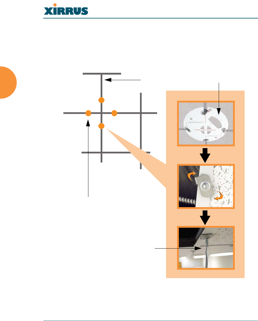
Attaching the T-Bar Clips
The T-bar clips are used to create four mounting points on the ceiling tile grid for
the Array mounting plate. Use the mounting template (provided) to find the
correct location for all four clamps. To attach the clamps, simply twist the clamps
onto the grid and tighten the screw post with a screwdriver.
Figure 25. Attaching the T-Bar Clips
Ceiling tile grid
T-bar clips (4 places)
Tighten the screw post
Template
Wireless LAN Array
Installing the Xirrus Array 45
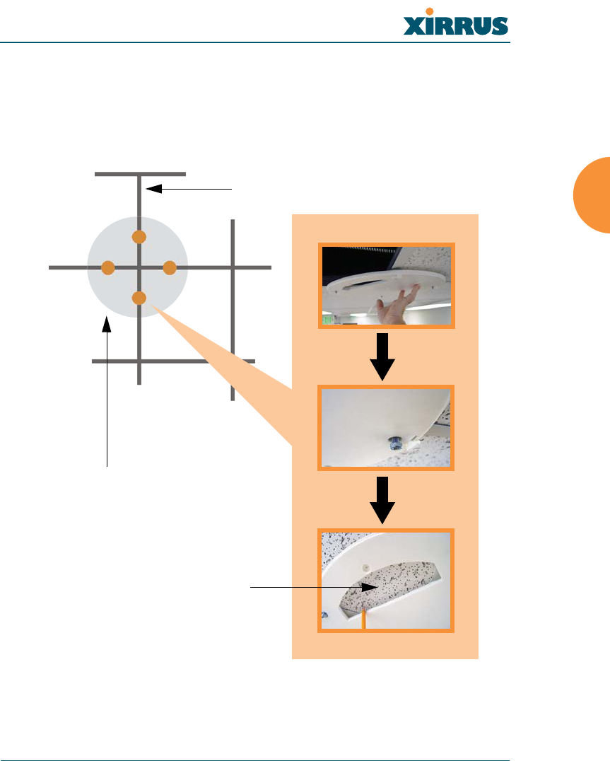
Installing the Mounting Plate
If necessary, orient the mounting plate (see “Attaching the T-Bar Clips” on
page 44) and locate the plate on the four screw posts. Secure the mounting plate to
the four clamps using the nuts provided. Once the mounting plate is secured, cut
an access hole in the ceiling tile for the cables.
Figure 26. Installing the Mounting Plate (XS-3900 shown)
Tile grid
Mounting Plate
Cut an access hole here
Wireless LAN Array
46 Installing the Xirrus Array
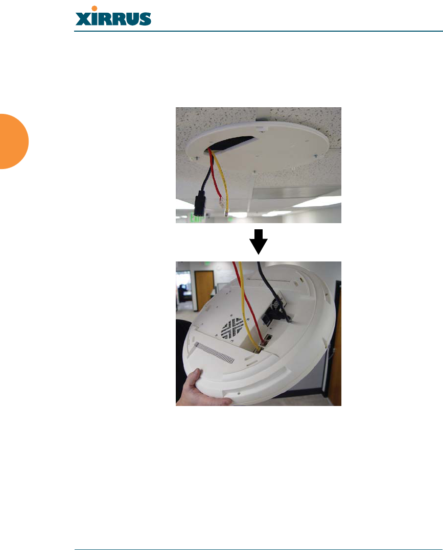
Connecting the Cables
Feed the power and Ethernet cables through the access hole in the tile and the
mounting plate (XS-3900), then connect the cables to the unit. See also, “Wiring
Considerations” on page 42.
Figure 27. Connecting the Cables
When the cables are connected, turn on the power switch—before attaching the
unit to the mounting plate (next step). Verify that the Ethernet link LED lights and
the LED boot sequence begins. The radio LEDs on the front of the unit will
illuminate in rotation, indicating that the Xirrus Array software is loading and the
unit is functioning correctly.
Wireless LAN Array
Installing the Xirrus Array 47
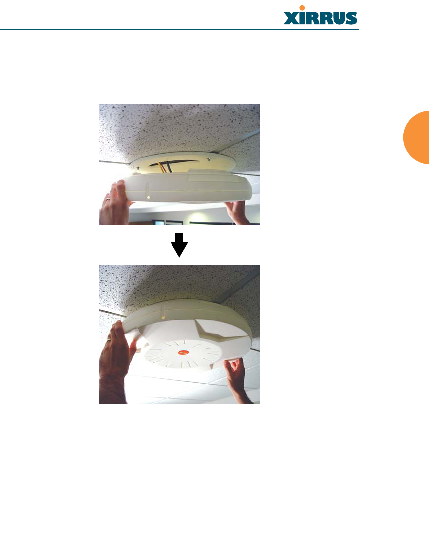
Attaching the Array to the Mounting Plate (XS-3900)
Align the port recess on the Array with the access hole in the mounting plate, then
connect the Array with the lugs on the mounting plate (4 places) and turn the
Array clockwise to lock the unit into place (similar to a smoke detector).
Figure 28. Attaching the Unit (XS-3900)
Wireless LAN Array
48 Installing the Xirrus Array
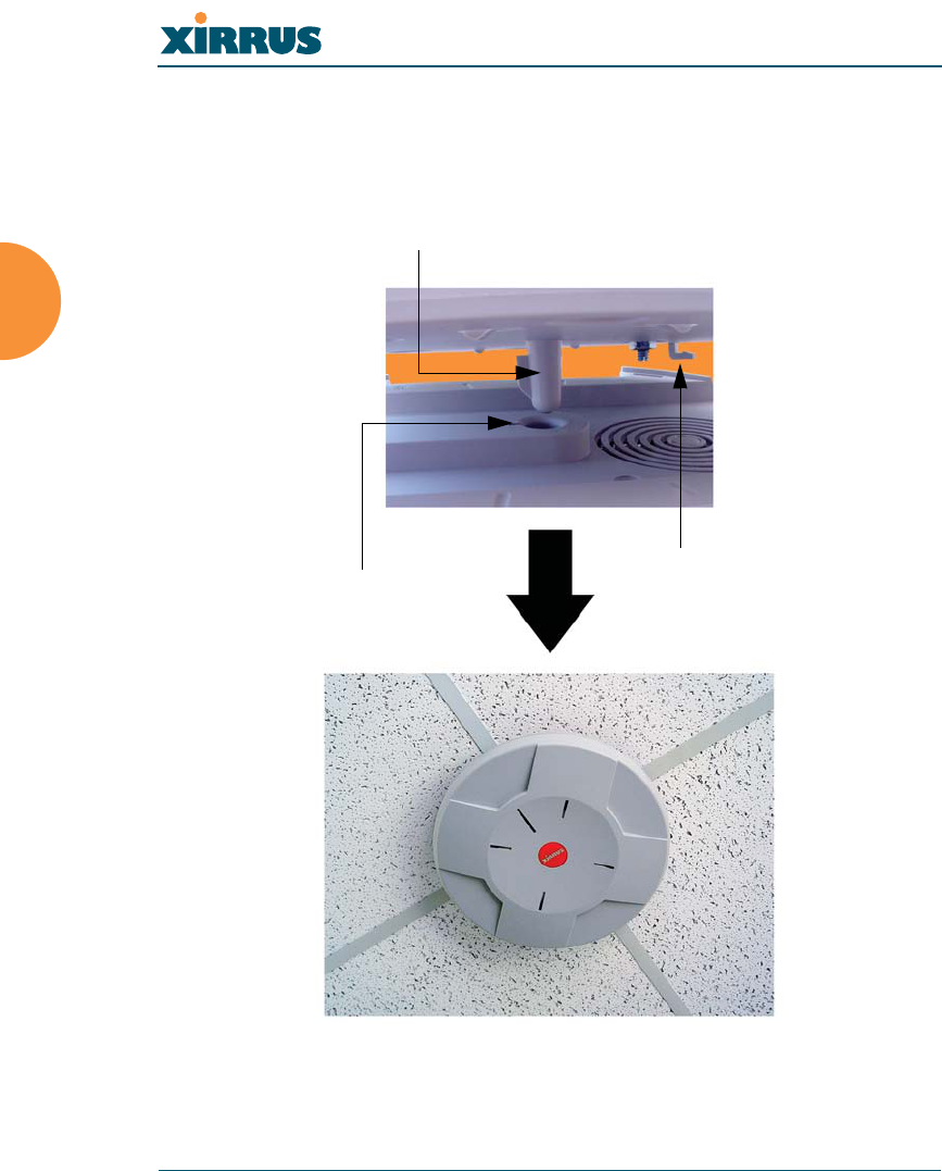
Attaching the Array to the Mounting Plate (XS-3500)
Align the XS-3500 Wireless LAN Array with the key post on the mounting plate,
then turn the Array to the right to lock the unit into place at the 4 lugs—similar to
a smoke detector.
Figure 29. Attaching the Unit (XS-3500)
Key post
Lug
Alignment hole
Wireless LAN Array
Installing the Xirrus Array 49
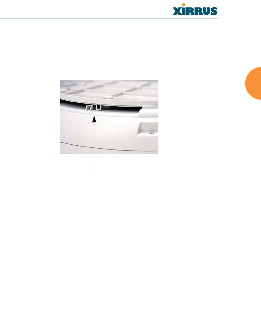
Securing the Array
For added security, there is a locking bracket incorporated into the mounting
plate, which will accept a small luggage-style padlock (if desired). There is also a
Kensington lock slot located near the Ethernet ports. In addition, the mounting
plate incorporates a positive locking tab that prevents the unit from being
inadvertently released.
Figure 30. Securing the Array
Now that the Array is physically installed, you must run the Express Setup
procedure from the unit’s Web Management Interface to enable the radios and
establish initial system configuration settings. Go to “Powering Up the Xirrus
Wireless LAN Array” on page 51.
Locking bracket
Wireless LAN Array
50 Installing the Xirrus Array
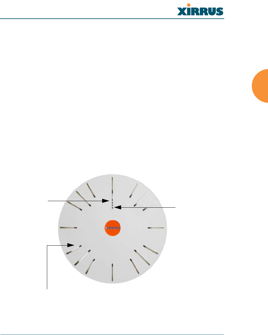
Dismounting the Array
To dismount the Array, place your fingers so as to increase the space between the
Array and the mounting plate at the positions indicated by the decals on the
mounting plate—these are aligned with IAPs (radios) abg1 and abg3, as indicated
on the clock-face of the Array.
Figure 31. IAP Positions (XS-3900)
a1
abg1
a2
a3
a4
abg2
a5
a6
a7
abg3
a8
a9
a10
abg4
a11
a12
Wireless LAN Array
Installing the Xirrus Array 51
Powering Up the Xirrus Wireless LAN Array
When powering up, the Array follows a specific sequence of LED patterns
showing the boot progress, and following a successful boot will provide extensive
status information. The normal boot sequence is as follows:
1. The green status LED will light first, showing a steady flashing while the
unit boots. In the event of a boot failure, this LED will change to flashing
red.
2. The Ethernet Link/Activity LEDs on the underside of the Array will light
for those ports connected to the network.
3. All IAP radio LEDs will light simultaneously.
4. While the Array is booting, a sequential LED pattern will cycle through
all the radio LEDs.
5. When the Array completes boot, the status LED will show a steady green,
and all radio lights will show the current state of those radios.
Figure 32. LED Locations (XS-3900)
Status LED
IAP LEDs (x16)
Ethernet
Activity LEDs
Wireless LAN Array
52 Installing the Xirrus Array
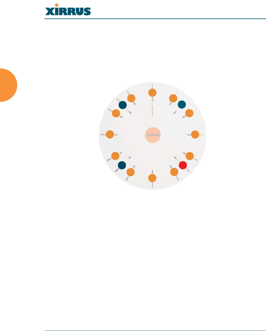
Once the unit is fully booted the default IAP LED display will be as follows:
zIAP radio LEDs that are enabled will show a steady orange for 802.11a
radios, or green for 802.11b/g radios.
zOnce a client associates with an individual IAP, that LED will show a
slow flash (heartbeat) pattern.
zWhen data is transmitted or received by an IAP, that IAP’s LED will flash.
The rate of flashing changes with the number of packets sent or received
per second—the LED will flash more quickly with a greater number of
packets per second and more slowly with lower numbers of packets per
second.
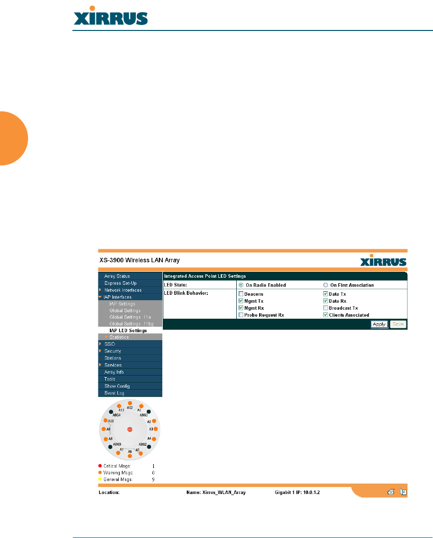
These settings may be altered or disabled entirely for diagnostic purposes or for
personal preference. Changes are made via the Array’s Command Line Interface
or the Web Management Interface—refer to “IAP LED Settings” on page 102.
Figure 33. WMI: IAP LED Settings Page
Wireless LAN Array
Installing the Xirrus Array 53
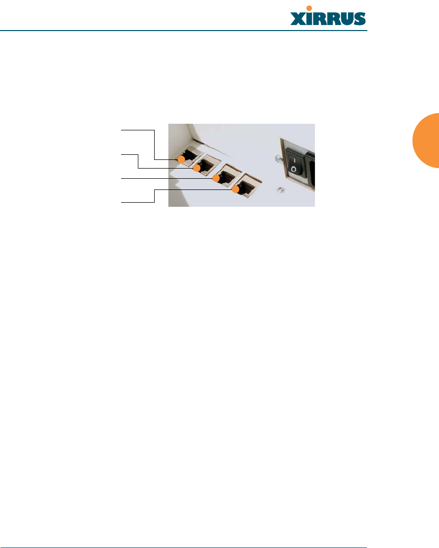
Establishing Communication with the Array
The Array can be configured through the Command Line Interface (CLI) or the
graphical Web Management Interface (WMI). You can use the CLI via the serial
management port, the Fast Ethernet port, or either of the Gigabit Ethernet ports.
You can use the WMI via any of the Array’s Ethernet ports.
Figure 34. Network Interface Ports
Using the Serial Port
If using the serial port to make your connection, use serial settings of 8 bits, no
parity, 1 stop bit (8N1) and a speed setting of 115200 baud. Use the
communication package of your choice.
Using the Ethernet Ports
If the Array is booted and does not receive DHCP addresses on either the Fast
Ethernet or Gigabit Ethernet ports, the Fast Ethernet port will default to an IP
address of 10.0.0.1 and both Gigabit Ethernet ports will default to 10.0.1.1 and
10.0.2.1 respectively. If the Array is connected to a network that provides DHCP
addresses, the IP address can be determined by the following two methods:
1. Examine the DHCP tables on the server and find the addresses assigned
to the Array (Xirrus MAC addresses begin with 000F7D).
2. Query the Array using the CLI via the serial port. Use the show ethernet
command to view the IP addresses assigned to each port.
Logging In
When logging in to the Array, use the default user name and password—the
default user name is admin, and the default password is admin.
Serial
Fast Ethernet
Gigabit 1
Gigabit 2
Wireless LAN Array
54 Installing the Xirrus Array
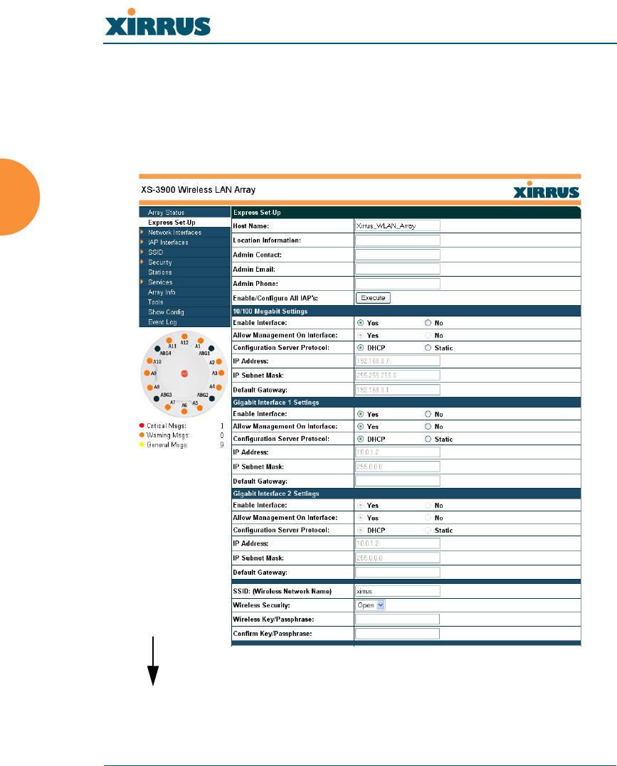
Performing the Express Setup Procedure
The Express Setup procedure allows you to establish global configuration settings
that will enable basic Array functionality. Any changes you make on this page
will affect all radios. When finished, click on the Apply button to apply the new
settings to this session, then click on the Save button to save your changes.
Figure 35. WMI: Express Setup Page (Part 1)
more ...
Wireless LAN Array
Installing the Xirrus Array 55
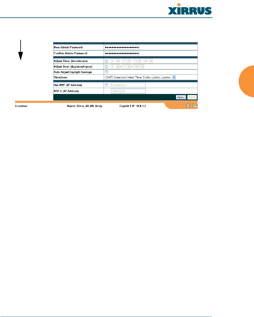
Figure 36. WMI: Express Setup Page (Part 2)
Procedure for Performing an Express Setup
1. Host Name: Specify a unique host name for this Array. The host name is
used to identify the Array on the network. Use a name that will be
meaningful within your network environment, up to 64 alphanumeric
characters.
2. Location Information: Enter a brief but meaningful description that
accurately defines the physical location of the Array. In an environment
where multiple units are installed, clear definitions for their locations are
important if you want to identify a specific unit.
3. Admin Contact: Enter the name and contact information of the person
who is responsible for administering the Array at the designated location.
4. Admin Email: Enter the email address of the admin contact you entered
in Step 3.
5. Admin Phone: Enter the telephone number of the admin contact you
entered in Step 3.
6. Enable/Configure All IAPs: Click on the Execute button to enable and
auto configure all IAPs (a message displays the countdown time—in
seconds—to complete the auto-configuration task).
... continued

Wireless LAN Array
56 Installing the Xirrus Array
7. Configure the Fast Ethernet (10/100 Megabit), Gigabit 1 and Gigabit 2
network interfaces. The fields for each of these interfaces are the same,
and include:
a. Enable Interface: Choose Yes to enable this network interface, or
choose No to disable the interface.
b. Allow Management on Interface: Choose Yes to allow management
of the Array via this network interface, or choose No to deny all
management privileges for this interface.
c. Configuration Server Protocol: Choose DHCP to instruct the Array
to use DHCP to assign IP addresses to the Array’s Ethernet interfaces,
or choose Static IP if you intend to enter IP addresses manually. If
you choose the Static IP option, you must enter the following
information:
zIP Address: Enter a valid IP address for this Array. To use
any of the remote connections (Web, SNMP, or SSH), a valid
IP address must be used.
zIP Subnet Mask: Enter a valid IP address for the subnet
mask (the default is 255.255.255.0). The subnet mask defines
the number of IP addresses that are available on the routed
subnet where the Array is located.
zDefault Gateway: Enter a valid IP address for the default
gateway. This is the IP address of the router that the Array
uses to forward data to other networks.
8. SSID (Wireless Network Name): The SSID (Service Set Identifier) is a
unique name that identifies a wireless network. All devices attempting to
connect to a specific WLAN must use the same SSID. The default for this
field is “xirrus.”
For additional information about SSIDs, go to the Multiple SSIDs section
of “Frequently Asked Questions” on page 222.

Wireless LAN Array
Installing the Xirrus Array 57
9. Wireless Security: Select the desired wireless security scheme (Open,
WEP or WPA). Make your selection from the choices available in the pull-
down list.
Open
This option offers no data encryption and is not recommended,
though you might choose this option if clients are required to use a
VPN connection through a secure SSH utility, like PuTTy.
WEP (Wired Equivalent Privacy)
An optional IEEE 802.11 function that offers frame transmission
privacy similar to a wired network. WEP generates secret shared
encryption keys that both source and destination stations can use to
alter frame bits to avoid disclosure to eavesdroppers.
WPA (Wi-Fi Protected Access)
A Wi-Fi Alliance standard that contains a subset of the IEEE 802.11i
standard, using TKIP or AES as an encryption method and 802.1X for
authentication. WPA is the stronger of the two wireless security
schemes.
For more information about security, including a full review of all
security options and settings, go to “Security Management” on page 113.
10. Wireless Key/Passphrase: Depending on the wireless security scheme
you selected, enter a unique WEP key or WPA passphrase.
a. Confirm Key/Passphrase: If you entered a WEP key or WPA
passphrase, confirm it here.
11. New Admin Password: If desired, enter a new administration password
for managing this Array. Choose a password that is not obvious, and one
that you can remember. If you forget your password, you must reset the
Array to its factory defaults so that the password is reset to admin (its
default setting).
#Security settings will only take effect if they are assigned to a specific
SSID. Refer to “SSID” on page 107.
Wireless LAN Array
58 Installing the Xirrus Array
a. Confirm Admin Password: If you entered a new administration
password, confirm the new password here.
12. Adjust Time (hrs:min:sec): Check this box if you want to adjust the
current system time. When the box is checked, the time fields become
active. Enter the revised time (hours, minutes, seconds, am/pm) in the
corresponding fields. If you don’t want to adjust the current time, this box
should be left unchecked (default).
13. Adjust Date (day/month/year): Check this box if you want to adjust the
current system date. When the box is checked, the date fields become
active. Enter the revised date (day, month, year) in the corresponding
fields. If you don’t want to adjust the current date, this box should be left
unchecked (default).
14. Auto Adjust Daylight Savings: Check this box if you want the system to
adjust for daylight savings automatically, otherwise leave this box
unchecked (default).
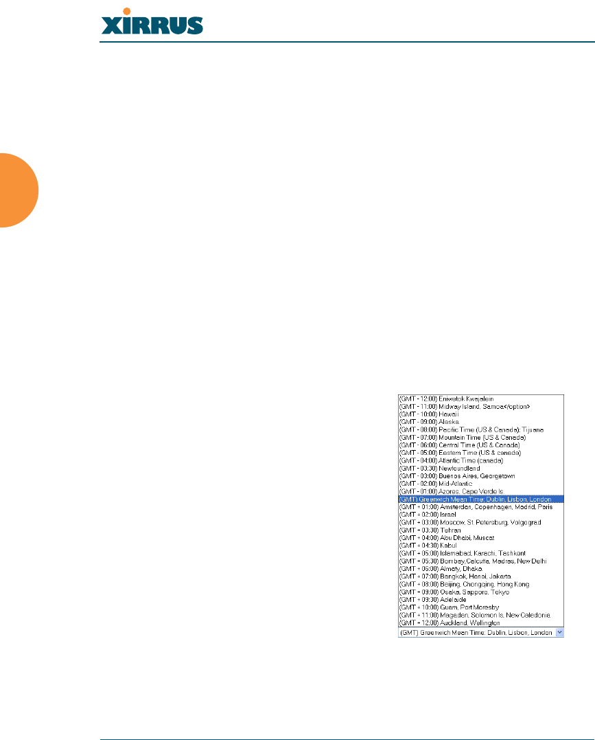
15. Time Zone: Select a time zone
from the choices available in the
pull-down list.
Figure 37. WMI: Time Zones
Wireless LAN Array
Installing the Xirrus Array 59
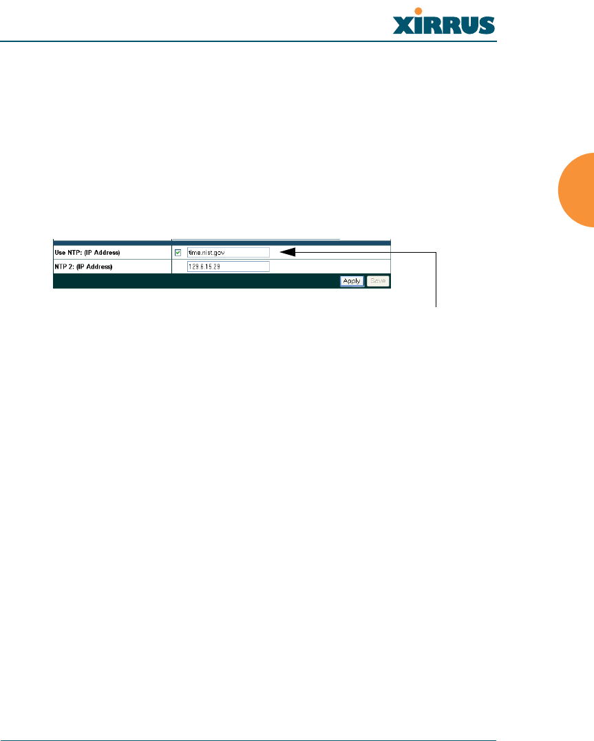
16. Use NTP (IP Address): Check this box if you want to use an NTP
(Network Time Protocol) server to synchronize the Array’s clock. This
ensures that syslog time-stamping is maintained across all units. Without
an NTP server assigned (no universal clock), each Array will use its own
internal clock and stamp times accordingly, which may result in
discrepancies. When this box is checked, the NTP and NTP 2 IP address
fields become active. If you don’t want to use an NTP server, leave this
box unchecked (default), otherwise enter the IP address or DNS name of
the NTP server.
Figure 38. Enabling the NTP Feature
a. NTP 2 (IP Address): If you enabled the NTP option and the site is
using a secondary NTP server, enter the IP address or DNS name of
the secondary NTP server.
17. Click on the Apply button to apply the new settings to this session
18. Click on the Save button to save your changes (otherwise your new
settings will not take effect).
This ends the Express Setup procedure.
NTP enabled

Wireless LAN Array
60 Installing the Xirrus Array
Installing the XS-3900 Wall Mount Assembly
The wall mounting assembly is used to mount the XS-3900 Wireless LAN Array
on a wall, instead of the traditional ceiling mount—where mounting the Array on
the ceiling may be impractical at your location.
Kit Contents
The Wall Mounting Assembly kit includes the following items:
z8 x SNAPTOGGLE™ toggle bolts (for attaching the wall bracket to the
wall)
z4 x 1/4 inch bolt assemblies (for attaching the mounting plate to the wall
bracket)
zWall Mounting Bracket
Tools Required
zPower drill
z1/2 inch (13mm) drill bit
zCross head screwdriver
z1/4 inch nut wrench
zPencil
zLevel
Wireless LAN Array
Installing the Xirrus Array 61
Mark the Wall Position
1. Use the Wall Mounting Bracket as a template and mark the locations on
the wall for the mounting holes.
Figure 39. Wall Mount—Marking the Holes
When marking the holes, ensure that the mounting plate is level—you
may need assistance.
#The bracket must be secured to the wall in at least 5 places, using a minimum
of the top 3 holes and the 2 outside holes at the bottom. For maximum strength,
use all 8 mounting points (8 toggle bolts are provided).
Mark holes (at least 5 places)
Wireless LAN Array
62 Installing the Xirrus Array
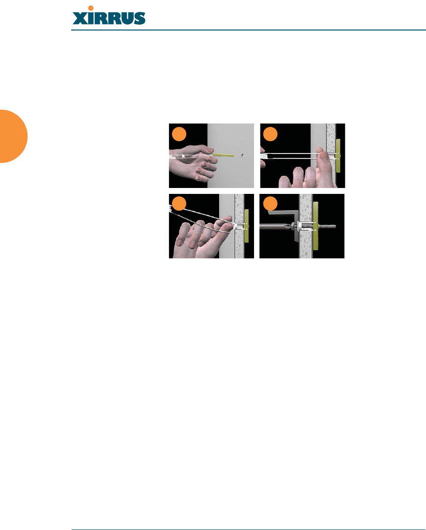
Install the SNAPTOGGLE™ Toggle Bolts
2. At the locations you marked in Step 1, drill a 1/2 inch (13mm) hole (there
must be a minimum clearance behind the wall of 1 7/8 inches (48mm).
3. (Refer to graphic A) Hold the metal channel flat alongside the plastic
straps and slide the channel through the hole.
Figure 40. Installing the Toggle Bolts
4. (Refer to graphic B) Hold the strap handle between your thumb and
forefinger and pull towards you until the metal channel rests flush
behind the wall.
To achieve the maximum shear holding capability for the toggle bolt, orient the
metal channel so that the channel is vertical to the floor.
Using your other hand, now slide the plastic cap along the straps until the
flange of the cap is flush with wall.
The straps provide a one-way ratcheting mechanism (similar to a cable tie).
Ensure that the toggle bolt assembly is oriented correctly (vertical to the floor)
before sliding the plastic cap along the straps.
5. (Refer to graphic C) Break the straps at the wall, flush with the flange of
the cap. The straps can be broken by pushing them from side-to-side and
simply snapping them off.
AB
C D
Wireless LAN Array
Installing the Xirrus Array 63
Graphic D shows a cutaway example of how the toggle bolt is used to
secure an item to the wall (in our case, the item is the Wall Mounting
Bracket—secured to the wall with a minimum of 5 toggle bolts.
Do not attach the Wall Mounting Bracket to the wall at this time.
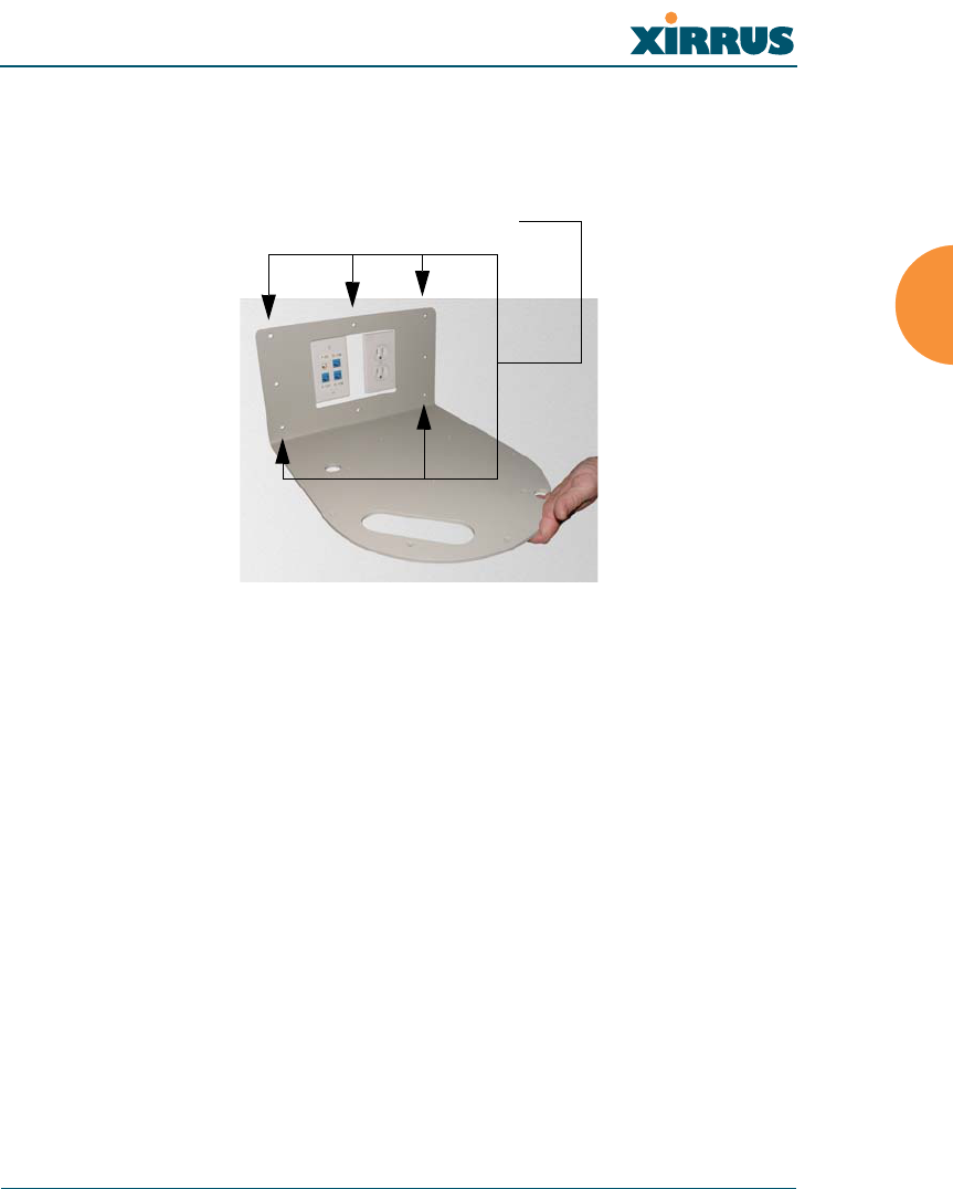
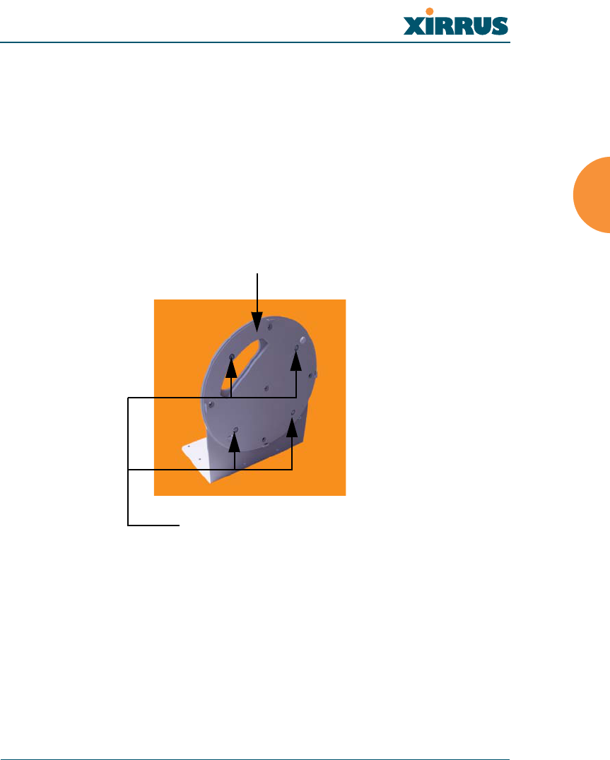
Attach the Mounting Plate to the Wall Mounting Bracket
Secure the Wireless LAN Array’s mounting plate to the Wall Mounting
Bracket (4 places)—tighten the 4 bolt assemblies to a torque of 10–12 lbf.ft
(1.38–1.66 kgf.m). Do not overtighten the bolts.
Figure 41. Attaching the Wall Mounting Plate
Attach the Wall Mounting Bracket/Plate Assembly to the Wall
6. Secure the Wall Mounting Bracket (with attached Mounting Plate) to the
wall at the toggle bolt anchors you created in Steps 2 through 5—a
minimum of 5 places.
Mounting Plate
Secure (x4 bolt assemblies)
Wireless LAN Array
64 Installing the Xirrus Array
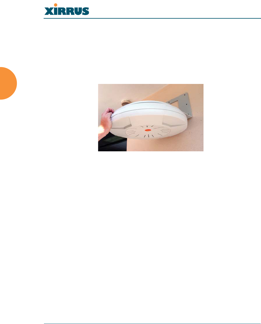
Mount the Array
The image opposite shows the orientation of the Wireless LAN Array when
mounted on a wall. It is not intended to show a fully installed Array.
7. Mount the Wireless LAN Array to the Wall Mounting Bracket in the same
way that you would mount the Array to a ceiling mount (the procedure is
identical).
Figure 42. Mounting the Array on a Wall
Wireless LAN Array
The Web Management Interface 65
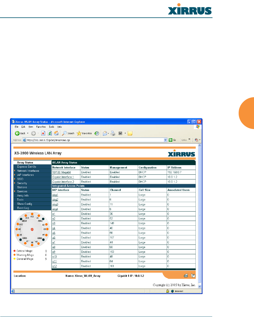
The Web Management Interface
This chapter provides an overview of the XS-3900’s embedded Web Management
Interface (WMI), used for establishing your network’s configuration settings and
wireless operating parameters.
An Overview
The WMI is an easy-to-use graphical interface to your Xirrus Array. It allows you
to configure the product to suit your individual requirements and ensure that the
unit functions efficiently and effectively.
Figure 43. Web Management Interface

Wireless LAN Array
66 The Web Management Interface
Content
The content of the WMI has been organized by function and hierarchy, shown
here in list form. You can click on any item in the list to jump to the referenced
destination.
Array Status
Express Setup
Network Interfaces
Network Settings
Network Statistics
DHCP Settings
DNS Settings
IAP Interfaces
IAP Settings
Global Settings
Global Settings .11a
Global Settings .11bg
IAP LED Settings
Statistics
(Individual IAP Statistics)
SSID
SSID Management
Security
Security Management
Radius Server
Radius User
MAC Access List
Admin Management
Rogue AP List
Rogue Control List
Stations
Services
Time Settings
System Log
SNMP
Array Info
Tools
Show Config
Event Log
Wireless LAN Array
The Web Management Interface 67
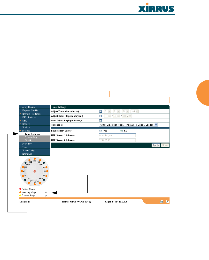
Structure
The WMI has been designed with simplicity in mind, making navigation quick
and easy. In the following example, you’ll see that pages are divided into left and
right frames. The left frame contains configuration elements organized by
function (for example, radio interfaces, security, etc.), and where these functions
are sub-divided there is an associated pull-down menu. Also included in the left
frame are three counters that provide a running total of messages generated by
the syslog subsystem during your session—organized into Critical, Warning and
Event messages.
Figure 44. WMI: Frames
The right frame contains the configuration parameters for the Array. This is
where you input data (if you want to make changes) or review the Array’s current
status and activity.
Left frame Right frame
Pull-down menu
Message counters
Wireless LAN Array
68 The Web Management Interface
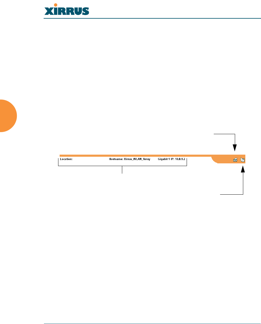
Status Bar
Below the configuration frames you will find a status bar containing information
about this Array, including:
zLocation—displays the location information assigned to the unit.
zHost name—the host name assigned to this unit.
zNetwork interface IP address—the IP address of the network interface
that is currently being used.
Also included in the status bar is a Print button and a Help button. Click on the
Print button to send a print file of the active page to your local printer, or click on
the Help button to go to the Array’s online help system.
Figure 45. WMI: Status Bar
Applying Configuration Changes
When you have defined all your settings on any WMI configuration page, you
must click on the Apply button for the changes to take effect in the current
session. Click on the Save button to write your changes (for future sessions).
Character Restrictions
When inputting strings in the WMI (for example, assigning SSIDs, host name,
password, etc.), use only common alphanumeric characters. Do not use any of the
following characters:
&<>' “/ \
Status information
Print button
Help button