Chamberlain Group The 8389 Overhead Door and Gate Operator User Manual 01 37718 indd

Chamberlain Group Inc, The Overhead Door and Gate Operator 01 37718 indd

User Manual_20160711_v1 - User Manual pt3 HCTDCU
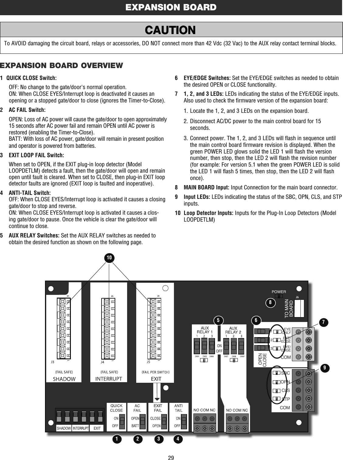
25ABCDRESET BUTTONThe reset button is located on the side of the control box and serves several functions:•   Press the reset button to stop a moving gate/door during a normal open/close cycle, like a stop button.•   Press the reset button once while the gate/door is in open position to disable the Timer-to-Close. The gate/door will stay in the open position. To restart the Timer-to-Close either press the reset button or activate the gate/door with a programmed remote control.•  Press the reset button to shut off the alarm and reset the operator.OPERATOR ALARMIf a contact sensor detects an obstruction twice consecutively the alarm will sound (up to 5 minutes) and the operator will need to be reset. If a command is given after the initial 5 minutes the operator will beep. The operator alarm will beep 3 times with a command if the battery is low.When the inherent force of the operator (RPM/current sensor) detects the following (twice consecutively) the alarm will sound (up to 5 minutes) and the operator will need to be reset:A. The gate/door hits an obstruction.B. The gate/door has a broken wheel(s) or damaged track.C. The gate/door has broken springs or hardware.D. Trolley is hitting the chassis or an unwanted object.Remove any obstructions. Toggle the reset switch to shut off the alarm and reset the operator. After the operator is reset, normal functions will resume. ADJUSTABLE OPEN SPEEDThe HCTDCU provides a high speed open option to help flow in high traffic areas. Select the open speed using the BIPART DELAY switch.BIPART DELAY OFF (default) = 8 in./sec. open speedBIPART DELAY ON (fast) = 11 in./sec. open speedNOTE: After changing the open speed, the force will need to be reset to account for the change of power used, see page 17.REMOTE CONTROLSINGLE BUTTON CONTROL (SBC) FUNCTIONALITYOnce the remote control has been programmed the operator will operate as follows:When gate/door is in the closed position, activation of the remote control button will open the gate/door. During the open cycle another activation of the remote control will stop the gate/door and the next activation of the remote control will close the gate/door.When the gate/door is in the open position, activation of the remote control button will close the gate/door. If the remote control is activated while the gate/door is closing, the gate/door will stop and the next activation will open the gate/door.OPERATIONReset Button
26 MANUAL DISCONNECTInsert key and turn to unlock position.The trolley will automatically re-engage when power is restored and run command is given. When the cylinder lock is in the locked position, the release ring will not disengage. If the cylinder lock is in the unlocked position, the release ring will always be accessible to disengage.Lift the gate/door up until fully open.Pull down the release ring.STEP 1 STEP 2STEP 3OPERATIONTo reduce the risk of SERIOUS INJURY or DEATH from a falling gate/door:•   If possible, use manual release to disengage trolley ONLY when gate/door is CLOSED. Weak or broken springs or unbalanced gate/door could result in an open gate/door falling rapidly and/or unexpectedly.•  NEVER use emergency release unless gate/door is clear of persons and obstructions.
27OUTInterruptLoopOUTExitLoopINShadowLoopOUTInterruptLoopOUTExitLoopINShadowLoopACCESSORY WIRINGComComComExitShadow(control board)InterruptEXTERNAL CONTROL DEVICESEXIT (2 Terminals)This input is a soft open command (maintained switch does not override external safeties and does not reset alarm condition). Used for exit probe, telephone entry, external exit loop detector, or any device that would command the gate/door to open.•   Opens a closing gate/door and holds open an open gate/door, if maintained, pauses Timer-to-Close at OPEN limit.SHADOW (2 Terminals)This input is used for external shadow loop detector when loop is positioned under the swing of the gate/door.•  Holds open gate/door at open limit•   Only active when the gate/door is at the OPEN limit, disregarded at all other times•  Pauses Timer-to-Close at OPEN limitINTERRUPT (2 Terminals)This input is used for photoelectric sensors and external interrupt loop detector when loop is on the outside of the gate/door.•  Holds open gate/door at OPEN limit•  Stops and reverses a closing gate/door to OPEN limit•   Pauses Timer-to-Close at OPEN limit, activates quick close and anti-tailgate features when enabled on the expansion boardEXTERNAL RESET BUTTONThe externally located reset button serves several functions:•   Press the reset button to stop a moving gate/door during a normal open/close cycle, like a stop button.•   Press the reset button once while the gate/door is in open position to disable the Timer-to-Close. The gate/door will stay in the open position. To restart the Timer-to-Close either press the reset button or activate the gate/door with a programmed remote control.•   Press the reset button to shut off the alarm and reset the operator.WIRING•   STOP and COM: Stops a moving gate/door.Hard stop (maintained switch overrides Open and Close commands and resets alarm condition). Cancels/resets Timer-to-Close at OPEN limit. Overrides Open and Close commands (within line-of-sight).RESETRESETCom(main control board)Stop
28ACCESSORY WIRINGMISCELLANEOUS WIRINGTHREE BUTTON CONTROL STATION (4 Terminals)•  OPEN and COM: Opens a closed gate/door.Hard open (maintained switch overrides external safeties and resets alarm condition). If maintained, pauses Timer-to-Close at OPEN limit. Opens a closing gate/door and holds open an open gate/door (within line-of-sight).•  CLOSE and COM: Closes an open gate/door.Hard close (maintained switch overrides external safeties and resets alarm condition within line-of-sight)•  STOP and COM: Stops a moving gate/door.Hard stop (maintained switch overrides Open and Close commands and resets alarm condition). Cancels/resets Timer-to-Close at OPEN limit. Overrides Open and Close commands (within line-of-sight).FIRE DEPARTMENT OPEN INPUT (2 Terminals)Acts as hard open. Hard open (maintained switch overrides external safeties and resets alarm condition). If maintained, pauses Timer-to-Close at OPEN limit.Opens a closing gate/door and holds open an open gate/door (within line-of-sight). Bypasses any pre-warning delay.ACCESSORY POWER 24 VDC, MAX 500 MA (4 Terminals)•  SWITCHED: Switched ON when the gate/door is in motion. Turns off after a 5 second delay when the gate/door stops. The power will remain ON at the open limit when Timer-to-Close is enabled and when the Timer-to-Close is counting down.•  UNSWITCHED: 24 Vdc voltage out to power accessories, always ON.ComOpen(Main control board)Three Button Control StationFire DepartmentComFire DeptAcc Power +24 VdcCom (-)(Main control board)Accessory Power UnswitchedAccessory Power SwitchedAcc Power +24 VdcCom (-)CloseStop N.C.
29EXPANSION BOARDEXPANSION BOARD OVERVIEWSBCOPNCLSSTPCOMEYEONLYEYE/EDGEEYE/EDGECOM123OPENCLOSETO MAINBOARDPOWER101 2 3 45 6 798To AVOID damaging the circuit board, relays or accessories, DO NOT connect more than 42 Vdc (32 Vac) to the AUX relay contact terminal blocks.1   QUICK CLOSE Switch:OFF: No change to the gate/door's normal operation.ON: When CLOSE EYES/Interrupt loop is deactivated it causes an opening or a stopped gate/door to close (ignores the Timer-to-Close). 2   AC FAIL Switch:OPEN: Loss of AC power will cause the gate/door to open approximately 15 seconds after AC power fail and remain OPEN until AC power is restored (enabling the Timer-to-Close).BATT: With loss of AC power, gate/door will remain in present position and operator is powered from batteries.3   EXIT LOOP FAIL Switch:   When set to OPEN, if the EXIT plug-in loop detector (Model LOOPDETLM) detects a fault, then the gate/door will open and remain open until fault is cleared. When set to CLOSE, then plug-in EXIT loop detector faults are ignored (EXIT loop is faulted and inoperative).4  ANTI-TAIL Switch:OFF: When CLOSE EYES/Interrupt loop is activated it causes a closing gate/door to stop and reverse.ON: When CLOSE EYES/Interrupt loop is activated it causes a clos-ing gate/door to pause. Once the vehicle is clear the gate/door will continue to close.5   AUX RELAY Switches: Set the AUX RELAY switches as needed to obtain the desired function as shown on the following page.6  EYE/EDGE Switches: Set the EYE/EDGE switches as needed to obtain the desired OPEN or CLOSE functionality.7   1, 2, and 3 LEDs: LEDs indicating the status of the EYE/EDGE inputs. Also used to check the firmware version of the expansion board:  1.  Locate the 1, 2, and 3 LEDs on the expansion board.  2.  Disconnect AC/DC power to the main control board for 15 seconds.  3.  Connect power. The 1, 2, and 3 LEDs will flash in sequence until the main control board firmware revision is displayed. When the green POWER LED glows solid the LED 1 will flash the version number, then stop, then the LED 2 will flash the revision number (for example: For version 5.1 when the green POWER LED is solid the LED 1 will flash 5 times, then stop, then the LED 2 will flash once).8   MAIN BOARD Input: Input Connection for the main board connector.9  Input LEDs: LEDs indicating the status of the SBC, OPN, CLS, and STP inputs. 10   Loop Detector Inputs: Inputs for the Plug-In Loop Detectors (Model LOOPDETLM)
30CYCLE COUNT*  First, note the current Aux Relay switch positions. To determine the actual cycles that the gate/door operator has run (in thousands), set all three Aux Relay switches to the ON setting for Aux Relay 1. The Expansion Board’s 1, 2, and 3 LEDs will blink out the cycle count, with 1 LED blinking 1000’s, 2 LED blinking 10,000’s, 3 LED blinking 100,000’s, and simultaneously all three LED’s blink 1,000,000’s (e.g. 1 LED blinks 3 times, 2 LED blinks 6 times, and 3 LED blinks once. Cycle count is 163,000.). Cycle count displayed is between 1,000 and 9,999,000 cycles. After servicing, set Aux Relay switches back to their appropriate positions. Cycle count cannot be reset or changed. If under 1,000 cycles the 1, 2, and 3 LEDs will turn on for 10 seconds, then turn off.NOTE: The expansion board will flash the cycle count 3 times then all the LEDs will turn on solid for 10 seconds then turn off.EXPANSION BOARDAUX RELAY WIRING EXAMPLEAUXILIARY RELAYSAUX RELAY SETTING SWITCH SETTINGS AUX RELAY 1 AUX RELAY 2123Off (no feature selected) OFF OFF OFF Relay always off. Use this Aux Relay setting to conserve battery power.Open Limit Switch OFF OFF ON Energizes at open limit. Use with SAMS (Sequenced Access Management System, jointly with barrier gate).Close Limit Switch OFF ON OFF Energizes when not at close limit. For an additional audible or visual display, connect an external light (low voltage).Gate/door Motion OFF ON ON Energizes when motor is on (gate/door in motion). For an additional audible or visual display, connect an external buzzer or light (low voltage).Pre-Motion Delay ON OFF OFF Energizes 3 seconds before gate/door motion and remains energized during gate/door motion. The onboard alarm will sound. For an additional audible or visual display, connect an external buzzer or light (low voltage).Energizes 3 seconds before gate/door motion and remains energized during gate/door motion. For an additional audible or visual display, connect an external buzzer or light (low voltage).Power ON ON OFF Energizes when AC power or solar power is present. There is approximately a 10-12 second delay before relay cutoff, after AC shutdown. Energizes when on battery power. There is approximately a 10-12 second delay before relay cutoff, after AC shutdown.Tamper ON OFF ON Energizes if gate/door is manually tampered with by being pushed off of close limit. For an additional audible or visual display, connect an external buzzer or light (low voltage).Energizes if gate/door is manually tampered with by being pushed off of close limit. For an additional audible or visual display, connect an external buzzer or light (low voltage).Cycle Quantity Feedback* ON ON ON The 1, 2, and 3 LEDs will blink out the cycle count (cycle count is stored on the control board). See below. Red/green light functionality, see below.AUX RELAY 1 AND 2Normally Open (N.O.) and Normally Closed (N.C.) relay contacts to control external devices, for connection of Class 2, low voltage (42 Vdc [34 Vac] max 5 Amps) power sources only. Function of relay contact activation determined by switch settings.Aux RelayClass 2 Power Source (42 Vdc [34 Vac],5 A max)Warning LightCOMN.C.N.O.+_SHADOW   INTERUPT      EXITSBCOPNCLSSTPCOMEYEONLYEYE/EDGEEYE/EDGECOM123OPENCLOSETO MAINBOARDPOWER SHADOW   INTERRUPT      EXITAUX RELAY 1 AUX RELAY 2AUX Relay 2 N.C.ComAUX Relay 2 N.O.AUX Relay 1 N.C.ComAUX Relay 1 N.O.AUXILIARY RELAY WIRING EXAMPLERED/GREEN LIGHT FUNCTIONALITYRed light wired to AUX RELAY 1. Green light wired to AUX RELAY 2.Gate/door STATE AUX RELAY 1 SWITCHES AUX RELAY 2 SWITCHES1 OFF 2 OFF 3 OFF 1 ON 2 ON 3 ONClosed Red light OFF*  Green light OFFOpening Red light ON/Flash Green light OFFOpen Red light OFF Green light ONClosing Red light ON/Flash Green light OFFDefined Mid Stop n/a n/aUndefined Mid Stop Red light ON Green light OFFTimer more than 5 seconds Red light OFF Green light ONTimer less than 5 seconds Red light ON/Flash Green light OFF*  For red light ON when gate/door is closed, set switch 1 on AUX RELAY 1 to ON
31EXPANSION BOARDWIRING ACCESSORIES TO THE EXPANSION BOARDAEntrapment Protection Device Inputs (4 terminals total), Open or Close Direction based on switch setting next to inputsEYES ONLY Input: Open or Close Direction Photoelectric Sensors, Close: reverses fully, Open: stops gate/doorEYES/EDGE Input(s): Open or Close Direction Photoelectric Sensors, Infra-red detector wired or Edge Sensor, Close: reverses fully, Open: stops gate/doorBSingle Button Control, SBC (2 terminals) Gate/door command sequence - Open, Stop, Close, Stop, ...Soft Open ,Soft Close, Soft Stop (maintained switch does not override external safeties and does not reset alarm condition)COpen Input (& common) (3-Button Control Station, 4 terminals total) Open command - opens a closed gate/door.Soft open (maintained switch does not override external safeties and does not reset alarm condition)If maintained, pauses Timer-to-Close at OPEN limit.Opens a closing gate/door and holds open an open gate/door.DClose Input (& common) (3-Button Control Station, 4 terminals total) Close command - closes an open gate/door.Soft close (maintained switch does not override external safeties and does not reset alarm condition)EStop Input (& common)(3-PB station, 4 terminals total) Stop command - stops a moving gate/door.Hard stop (maintained switch overrides Open and Close commands and resets alarm condition)If maintained, pauses Timer-to-Close at OPEN limit.Overrides an Open or Close command.FExit Loop Input (2 terminals) Loop wire connection for plug-in loop detector when loop is inside secured area near gate/door.Open command - opens a closed gate/door.Soft open (maintained switch does not override external safeties and does not reset alarm condition)If maintained, pauses Timer-to-Close at OPEN limit.Opens a closing gate/door and holds open an open gate/door.GShadow Loop Input (2 terminals) Loop wire connection for plug-in loop detector when loop is positioned under the gate/door.  - Holds open gate/door at open limit  - Disregarded during gate/door motion   - Pauses Timer-to-Close at Open LimitHInterrupt Loop Input (2 terminals) Loop wire connection for plug-in loop detector when loop is along the side of the gate/door.  - Holds open gate/door at open limit  - Stops and reverses a closing gate/door  - Pauses Timer-to-Close at Open Limit  - Activates quick close and anti-tail features if enabledRefer to the chart below and the corresponding image for a description of the expansion board inputs.SBCOPNCLSSTPCOMEYEONLYEYE/EDGEEYE/EDGECOM123OPENCLOSETO MAINBOARDPOWERGFHECDBAPhotoelectric SensorPhotoelectric Sensor or EdgePhotoelectric Sensor or EdgeExit LoopInterrupt LoopShadow LoopN.C.
32MAINTENANCETo reduce the risk of SEVERE INJURY or DEATH:•  READ AND FOLLOW ALL INSTRUCTIONS.•  ALL maintenance MUST be performed by a LiftMaster professional.•   ANY maintenance to the operator or in the area near the operator MUST NOT be performed until disconnecting the electrical power (AC or solar and battery) and locking-out the power via the operator power switch. Upon completion of maintenance the area MUST be cleared and secured, at that time the unit may be returned to service.•   NEVER let children operate or play with gate/door controls. Keep the remote control away from children.•   ALWAYS keep people and objects away from the gate/door. NO ONE SHOULD CROSS THE PATH OF THE MOVING GATE/DOOR.•   The entrance is for vehicles ONLY. Pedestrians MUST use separate entrance.•   Test the gate/door operator monthly. The gate/door MUST reverse on contact with a rigid object or reverse when an object activates the non-contact sensors. After adjusting the force or the limit of travel, retest the gate/door operator. Failure to adjust and retest the gate/door operator properly can increase the risk of INJURY or DEATH.•   Use the manual disconnect release ONLY when the gate/door is not moving.•   KEEP GATES/DOORS PROPERLY MAINTAINED. Read the owner’s manual. Have a qualified service person make repairs to gate/door hardware.•   Activate gate/door ONLY when it can be seen clearly, is properly adjusted and there are no obstructions to gate/door travel.•   To reduce the risk of FIRE or INJURY to persons use ONLY LiftMaster part 29-NP712 for replacement batteries.•   SAVE THESE INSTRUCTIONS.•   ALWAYS wear protective gloves and eye protection when changing the battery or working around the battery compartment.IMPORTANT SAFETY INFORMATIONMAINTENANCE CHARTDisconnect all power (AC, solar, battery) to the operator before servicing. The operator's AC Power switch ONLY turns off AC power to the control board and DOES NOT turn off battery power. ALWAYS disconnect the batteries to service the operator.BATTERIESBatteries will degrade over time depending on temperature and usage. The operator alarm will beep 3 times with a command if the battery is low. Batteries do not perform well in extremely cold temperatures. For best performance, the batteries should be replaced every 3 years. Use only LiftMaster part 29-NP712 for replacement batteries. The operator comes with two 7AH batteries. The batteries contain lead and need to be disposed of properly. DESCRIPTION TASK CHECK AT LEAST ONCE EVERYMONTH 6 MONTHS 3 YEARSEntrapment Protection Devices Check and test for proper operation XWarning Signs Make sure they are present XManual Disconnect Check and test for proper operation XGate/door Make sure the gate/door operates smoothly without the operator. XGate/door Track Make sure the gate/door track runs smoothly. XAccessories Check all for proper operation XElectrical Inspect all wire connections XOperator Inspect for wear or damage XChain For chain maintenance, adjust the turnbuckle. XBatteries Replace X
33TROUBLESHOOTINGDIAGNOSTICS DISPLAY OPEN, CLOSE, & STOP BUTTONSTo protect against fire and electrocution:•   DISCONNECT power (AC or solar and battery) BEFORE installing or servicing operator.For continued protection against fire:•  Replace ONLY with fuse of same type and rating.Press and hold the STOP button......then press and hold the CLOSE button...TO VIEW THE CODESThe codes will show on the diagnostic display.TO SCROLL THROUGH THE SAVED CODESPress the OPEN button to cycle to the most recent code ("01"). Press the CLOSE button to cycle to the oldest code (up to "20").A SECOND LATER....The operator will only keep track of up to 20 codes, then will start saving over the oldest codes as new codes occur. The operator will show the code sequence number followed by the code number:NOTE: When cycling or disconnecting power (ac/dc) to the control board, it is recommended that you unplug the J15 plug....then press and hold the OPEN button until "Er" shows on the display.CODE NUMBERThe second number shown after the code sequence number is the code itself (31-99, example" "31"). Refer to the chart on the following page for an explanation of each code.CODE SEQUENCE NUMBERThe first number shown is the most recent code (example: "01"). The display will show the sequence of codes that occurred starting with "01" and going up to code "20". TO EXITPress and release the STOP button to exit. The display will also time out after two minutes of inactivity.TO RESET THE CODE HISTORY1.   Press and hold the STOP button for six seconds. The display will show "Er" then "CL" alternately for six seconds.2.   Release the STOP button. The code history has now been reset and the display will show "- -" until a new code occurs.3.  Press and release the STOP button to exit.DIAGNOSTIC CODES
34TROUBLESHOOTINGDIAGNOSTIC CODESSome codes are saved in the code history and some are not. If a code is not saved it will briefly appear on the display as it occurs, then disappear.Code Meaning Solution Saved31 Main control board has experienced an internal failure. Disconnect all power, wait 15 seconds, then reconnect power (reboot). If issue continues, replace main control board. NO34 Absolute Position Encoder Error, not getting position information from encoder Check APE assembly and wiring connections. Replace the APE assembly if necessary. YES35 Max-Run-Time Exceeded Error Check for an obstruction, then reprogram the limits. YES36 Product ID Error Was the control board just replaced? If so, erase limits, enter limit setup mode and set limits. If not, disconnect all power, wait 15 seconds, then reconnect power before changing product ID harness. YES37 Product ID Failure Unplug product ID harness then plug back in. Disconnect all power, wait 15 seconds, then reconnect power before replacing product ID harness. YES38 Hard Stop Limit Limit may be set too tightly against a non-resilient hard stop (re-adjust limit). Operator may be at end of travel (re-adjust mounting). NO40 Battery overvoltage Too much voltage on the battery. Check harness. Make sure there is NOT a 24V battery on a 12V system. YES41 Battery overcurrent Possible short of the battery charge harness. Check harness. Make sure you do NOT have a 12V battery on a 24V system. YES42 No battery at boot up Check battery connections and installation. Replace batteries if depleted to less than 20V on a 24V system or less than 10V on a 12V system. Make sure there is NOT a single 12V battery on a 24V system. YES43 Exit Loop Error Failure or missing loop (SHORT or OPEN - LiftMaster Plug-in Loop Detector only) Check loop wiring throughout connection. May be a short in the loop, or an open connection in the loop. YES44 Shadow Loop Error 45 Interrupt Loop Error 46 Wireless edge battery low Replace batteries in wireless edge. YES50 Door out of balance detected Check counterbalance spring condition and setting. YES53 Brownout occurred AC/DC board supply dipped below allowable level. Review power supply and wiring. If rebooting, ensure enough time for discharge of power to force a fresh boot. YESLiftMaster System Installed System Informational External Entrapment ProtectionInherent Entrapment Protection
35TROUBLESHOOTINGDIAGNOSTIC CODESSome codes are saved in the code history and some are not. If a code is not saved it will briefly appear on the display as it occurs, then disappear.Code Meaning Solution Saved60 Minimum number of monitored entrapment protection devices (one) not installed. Review monitored entrapment protection device connections. A minimum of one monitored entrapment protection device protecting the close direction must be installed to allow operation. NO61 CLOSE EYE/INTERRUPT held more than 3 minutes  Check wired input on main control board; check for alignment or obstruction. YES62 CLOSE EDGE held more than 3 minutes63 OPEN EYE/EDGE held more than 3 minutes64 CLOSE EYE/INTERRUPT held more than 3 minutes Check wired input on expansion board; check for alignment or obstruction. YES65 CLOSE EYE/EDGE held more than 3 minutes66 OPEN EYE/EDGE held more than 3 minutes67 Wireless edge triggered more than 3 minutes Check wired input for wiring issue or obstruction. YES68 Wireless edge loss of monitoring Check wireless edge inputs. YES69 Wireless edge triggered IF an obstruction occurred, no action required. If an obstruction did NOT occur, check inputs and wiring. NO70 CLOSE EYE/INTERRUPT triggered, causing reversal, preventing close, or resetting TTCIF an obstruction occurred, no action required. If an obstruction did NOT occur, check alignment, inputs, and wiring on main control board. NO71 CLOSE EDGE triggered, causing reversal, preventing close, or canceling TTC72 OPEN EYE/EDGE triggered, causing reversal or preventing opening73 CLOSE EYE/INTERRUPT triggered, causing reversal, preventing close, or resetting TTCIF an obstruction occurred, no action required. If an obstruction did NOT occur, check alignment, inputs, and wiring on expansion board. NO74 CLOSE EYE/EDGE triggered, causing reversal and preventing close or canceling TTC75 OPEN EYE/EDGE triggered, causing reversal or preventing opening82 Close input (EYE/EDGE) communication fault (expansion board) Check the connections between the main board and the expansion board.  YES83 Open input (EYE/EDGE) communication fault (expansion board)91 Force Reversal Check for obstruction. If no obstruction, check that the mechanical assembly is engaged and free to move. See section on Limit and Force Adjustment, and Obstruction Test. YES93 RPM / STALL Reversal Check for obstruction. If no obstruction, check the operator wiring and that the mechanical assembly is engaged and free to move. Replace APE assembly. YES99 Normal Operation No action required YESLiftMaster System Installed System Informational External Entrapment ProtectionInherent Entrapment Protection
36TROUBLESHOOTINGCONTROL BOARD LEDSSTATUS LEDS INPUT LEDSINPUT LEDSOPEN, CLOSE, & STOP INPUT OFF Input inactiveON Input activeBLINK Input active on other operatorFIRE DEPT INPUT OFF Input inactiveON Input activeBLINK Input active on other operatorEXIT OFF Input inactiveON Input activeBLINK Input active on other operatorSHADOW OFF Input inactiveON Input activeBLINK Input active on other operatorCLOSE EYES/INTERRUPT OFF Input inactiveON Input activeBLINK Input active on other operatorCLOSE EDGE OFF Input inactiveON Input activeBLINK Input active on other operatorOPEN EYES/EDGE OFF Input inactiveON Input activeBLINK Input active on other operatorLOCK OFF Maglock relay inactiveON Maglock relay activeSTATUS LEDSINPUT POWER OFF OFF stateON AC charger or Solar power availableBATT CHARGING OFF Not chargingON Three stage battery chargingTIMER OFF The timer is disabledON The timer is enabledMEDIUM BLINK (1 blink per second) The timer is runningFAST BLINK (2 blinks per second) The timer is pausedFASTEST BLINK (8 blinks per second) The timer is canceledGATE/DOOR MOVINGOFF The gate/door is stoppedON The gate/door is opening or closingMEDIUM BLINK (1 blink per second) Operator is in E1 (single entrapment)FASTEST BLINK (8 blinks per second) The operator is in E2 (double entrapment)BATT LOW OFF No battery errorON Battery lowBLINK (1 blink per second) Battery critically lowACC PWR OVLD OFF OFF stateON Accessory overload protector opened

Navigation menu