Chamberlain Group The 8389 Overhead Door and Gate Operator User Manual 01 37718 indd
Chamberlain Group Inc, The Overhead Door and Gate Operator 01 37718 indd
Contents
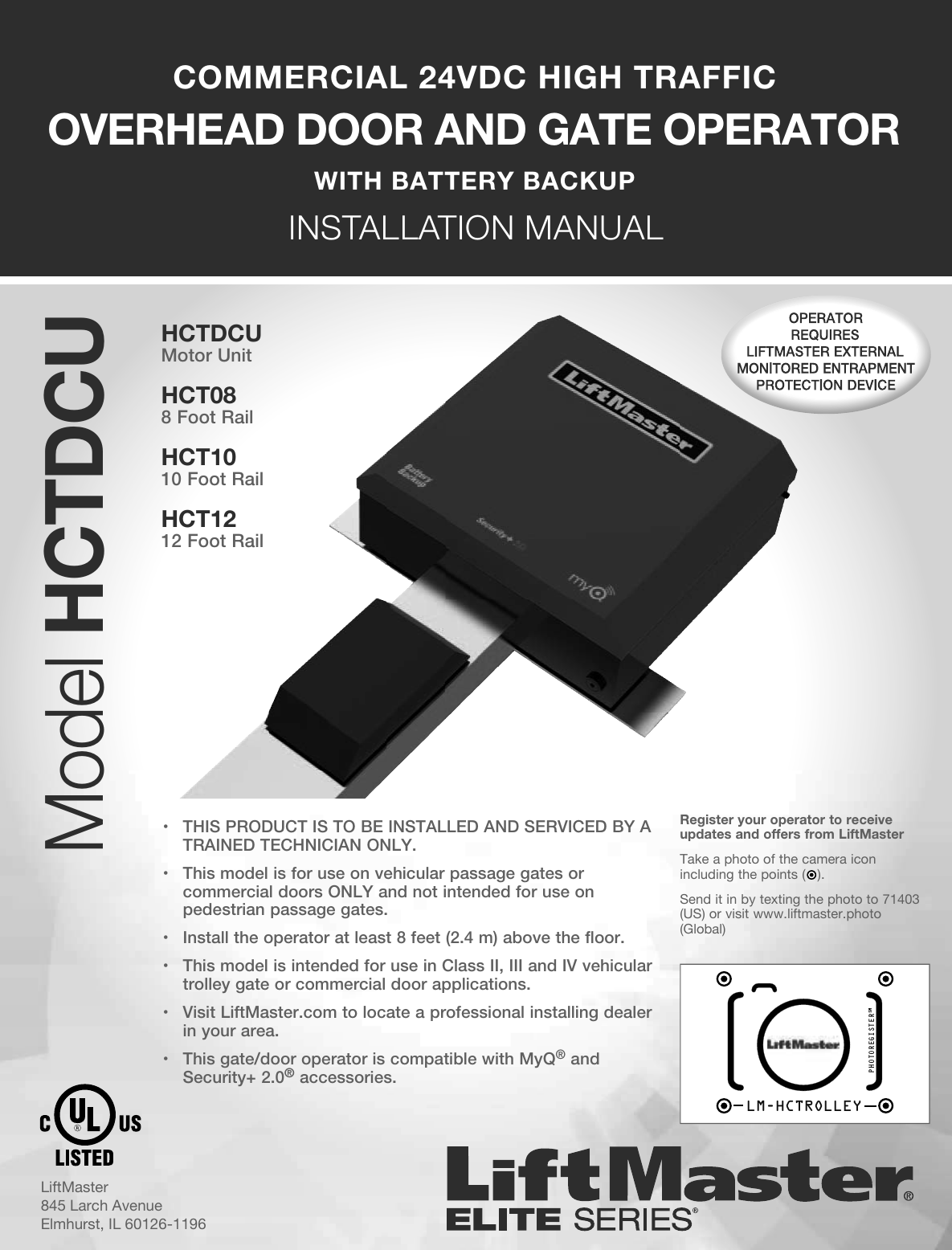
- 1. User Manual_20160711_v1 - User Manual pt1 HCTDCU
- 2. User Manual_20160711_v1 - User Manual pt2 HCTDCU
- 3. User Manual_20160711_v1 - User Manual pt3 HCTDCU
- 4. User Manual_20160711_v1 - User Manual pt4 HCTDCU
- 5. User Manual_20160711_v1 - User Manual pt5 HCTDCU
- 6. User Manual_20160711_v1 - User Manual pt6 HCTDCU
- 7. User Manual_20160711_v1 - User Manual pt7 HCTDCU
- 8. User Manual_20160711_v1 - User Manual pt8 HCTDCU
User Manual_20160711_v1 - User Manual pt1 HCTDCU