Chantry Networks APXXX1 HiPATH WIRELESS ACCESS POINT (AP) User Manual HiPath Wireless Standalone Access Point User Guide
Chantry Networks Inc. (a Siemens Company) HiPATH WIRELESS ACCESS POINT (AP) HiPath Wireless Standalone Access Point User Guide
Contents
USERS MANUAL 2

HiPath Wireless
Standalone Access Point, V1.0
User Guide

*1PA31003-W1110-U100-1-7619*
1P A31003-W1110-U100-1-7619
The information provided in this document contains merely general descriptions or
characteristics of performance which in case of actual use do not always apply as
described or which may change as a result of further development of the products.
An obligation to provide the respective characteristics shall only exist if expressly
agreed in the terms of contract. The trademarks used are owned by Siemens Enterprise
Communications GmbH & Co. KG or their respective owners.
Warning
Hackers who unlawfully gain access to customer telecommunications systems are criminals.
Currently, we do not know of any telecommunications system that is immune to this type of
criminal activity. Siemens Enterprise Communications GmbH & Co. KG will not accept liability
for any damages which result from unauthorized use. Although Siemens has designed
security features into its products, it is your sole responsibility to use the security features and
to establish security practices within your company, including training, security awareness,
and call auditing.
Siemens sales and service personnel, as well as Siemens business partners, are available
to work with you to help you guard against this unauthorized use of your telecommunications
system.
February 2007
No part of this publication may be reproduced, stored in a retrieval system, or transmitted, in
any form or by any means, mechanical, electronic, photocopying, recording, or otherwise,
without prior written permission of Siemens. The software described in this publication is
furnished under a license agreement and may be used only in accordance with the terms of
that agreement.
Request Siemens publications from your Siemens representative or the Siemens branch
serving you.
Copyright © 2007 Siemens Enterprise Communications GmbH & Co. KG. All rights reserved.
© Siemens Enterprise Communications GmbH & Co. KG 2007,
Hofmannstraße 51, D-81359 München, Germany
Reference No.: A31003-W1110-U100-1-7619
Subject to availability. Right of modification reserved.

HiPath_Wireless_StandaloneTOC.fm
A31003-W1110-U100-1-7619, DRAFT February 2007
HiPath Wireless Standalone Access Point V1.0, User Guide 3
Nur für den internen Gebrauch Content
Content 0
1 Welcome . . . . . . . . . . . . . . . . . . . . . . . . . . . . . . . . . . . . . . . . . . . . . . . . . . . . . . . . . . . . . . 5
1.1 About this user guide . . . . . . . . . . . . . . . . . . . . . . . . . . . . . . . . . . . . . . . . . . . . . . . . . . . . 5
1.2 Who should use this user guide?. . . . . . . . . . . . . . . . . . . . . . . . . . . . . . . . . . . . . . . . . . . 5
1.3 Chapter descriptions . . . . . . . . . . . . . . . . . . . . . . . . . . . . . . . . . . . . . . . . . . . . . . . . . . . . 6
1.4 Related documentation . . . . . . . . . . . . . . . . . . . . . . . . . . . . . . . . . . . . . . . . . . . . . . . . . . 7
1.5 Formatting conventions . . . . . . . . . . . . . . . . . . . . . . . . . . . . . . . . . . . . . . . . . . . . . . . . . . 7
1.6 Package contents . . . . . . . . . . . . . . . . . . . . . . . . . . . . . . . . . . . . . . . . . . . . . . . . . . . . . . 7
2 Regulatory information . . . . . . . . . . . . . . . . . . . . . . . . . . . . . . . . . . . . . . . . . . . . . . . . . . 9
2.1 AP2630 Internal Antenna AP, AP2640 External Antenna AP . . . . . . . . . . . . . . . . . . . . 10
2.1.1 United States – FCC Declaration of Conformity Statement . . . . . . . . . . . . . . . . . . 11
2.1.2 Canada - Department of Communications Compliance Statement. . . . . . . . . . . . . 19
2.1.3 European Community . . . . . . . . . . . . . . . . . . . . . . . . . . . . . . . . . . . . . . . . . . . . . . . 26
2.1.4 Certifications of Other Countries . . . . . . . . . . . . . . . . . . . . . . . . . . . . . . . . . . . . . . . 38
2.2 Country support list . . . . . . . . . . . . . . . . . . . . . . . . . . . . . . . . . . . . . . . . . . . . . . . . . . . . 39
3 About the HiPath Wireless Standalone Access Point . . . . . . . . . . . . . . . . . . . . . . . . . 45
3.1 Understanding conventional wireless LANs. . . . . . . . . . . . . . . . . . . . . . . . . . . . . . . . . . 45
3.2 Understanding the Standalone Access Point . . . . . . . . . . . . . . . . . . . . . . . . . . . . . . . . 46
3.3 Standalone Access Point and your network . . . . . . . . . . . . . . . . . . . . . . . . . . . . . . . . . 46
3.3.1 Standalone Access Point network components . . . . . . . . . . . . . . . . . . . . . . . . . . . 46
3.3.2 About network security . . . . . . . . . . . . . . . . . . . . . . . . . . . . . . . . . . . . . . . . . . . . . . 47
3.3.3 About Quality of Service . . . . . . . . . . . . . . . . . . . . . . . . . . . . . . . . . . . . . . . . . . . . . 48
3.4 About clustering . . . . . . . . . . . . . . . . . . . . . . . . . . . . . . . . . . . . . . . . . . . . . . . . . . . . . . . 48
3.4.1 Forming a cluster. . . . . . . . . . . . . . . . . . . . . . . . . . . . . . . . . . . . . . . . . . . . . . . . . . . 48
4 Installing and configuring the Standalone Access Point . . . . . . . . . . . . . . . . . . . . . . 49
4.1 Installing a Standalone Access Point. . . . . . . . . . . . . . . . . . . . . . . . . . . . . . . . . . . . . . . 49
4.2 Connecting and powering the Standalone Access Point . . . . . . . . . . . . . . . . . . . . . . . . 50
4.3 Understanding Standalone Access Point LED status . . . . . . . . . . . . . . . . . . . . . . . . . . 51
4.4 Restoring the factory default settings . . . . . . . . . . . . . . . . . . . . . . . . . . . . . . . . . . . . . . 52
5 Getting started with a Standalone Access Point . . . . . . . . . . . . . . . . . . . . . . . . . . . . . 53
5.1 About the interface. . . . . . . . . . . . . . . . . . . . . . . . . . . . . . . . . . . . . . . . . . . . . . . . . . . . . 53
5.2 Logging on to the Standalone Access Point . . . . . . . . . . . . . . . . . . . . . . . . . . . . . . . . . 53
5.3 Changing passwords . . . . . . . . . . . . . . . . . . . . . . . . . . . . . . . . . . . . . . . . . . . . . . . . . . . 55
5.4 Downloading the firmware . . . . . . . . . . . . . . . . . . . . . . . . . . . . . . . . . . . . . . . . . . . . . . . 56
5.5 Setting the interface language . . . . . . . . . . . . . . . . . . . . . . . . . . . . . . . . . . . . . . . . . . . . 57
5.6 Changing the host IP address . . . . . . . . . . . . . . . . . . . . . . . . . . . . . . . . . . . . . . . . . . . . 58
5.7 Accessing help. . . . . . . . . . . . . . . . . . . . . . . . . . . . . . . . . . . . . . . . . . . . . . . . . . . . . . . . 59
6 Configuring a Standalone Access Point. . . . . . . . . . . . . . . . . . . . . . . . . . . . . . . . . . . . 61
6.1 Configuring the LAN settings . . . . . . . . . . . . . . . . . . . . . . . . . . . . . . . . . . . . . . . . . . . . . 61

Content Nur für den internen Gebrauch
A31003-W1110-U100-1-7619, DRAFT February 2007
4HiPath Wireless Standalone Access Point V1.0, User Guide
HiPath_Wireless_StandaloneTOC.fm
6.2 Configuring the wireless settings . . . . . . . . . . . . . . . . . . . . . . . . . . . . . . . . . . . . . . . . . 63
6.2.1 Configuring the wireless basic settings . . . . . . . . . . . . . . . . . . . . . . . . . . . . . . . . . 64
6.2.2 Configuring the wireless filter settings . . . . . . . . . . . . . . . . . . . . . . . . . . . . . . . . . . 65
6.2.3 Configuring the advanced 802.11b/g settings . . . . . . . . . . . . . . . . . . . . . . . . . . . . 67
6.2.4 Configuring the advanced 802.11a settings . . . . . . . . . . . . . . . . . . . . . . . . . . . . . . 71
6.2.5 Configuring the wireless Quality of Service (QoS) settings . . . . . . . . . . . . . . . . . . 74
6.3 Configuring VNS for the Standalone Access Point . . . . . . . . . . . . . . . . . . . . . . . . . . . . 75
6.3.1 Configuring the general VNS configuration . . . . . . . . . . . . . . . . . . . . . . . . . . . . . . 75
6.3.2 Configuring VNS radio frequency settings . . . . . . . . . . . . . . . . . . . . . . . . . . . . . . . 77
6.3.3 Configuring VNS security settings . . . . . . . . . . . . . . . . . . . . . . . . . . . . . . . . . . . . . 78
6.3.4 Configuring VNS QoS settings . . . . . . . . . . . . . . . . . . . . . . . . . . . . . . . . . . . . . . . . 82
6.4 Managing configuration. . . . . . . . . . . . . . . . . . . . . . . . . . . . . . . . . . . . . . . . . . . . . . . . . 87
6.4.1 Saving a configuration . . . . . . . . . . . . . . . . . . . . . . . . . . . . . . . . . . . . . . . . . . . . . . 87
6.4.2 Restoring a configuration . . . . . . . . . . . . . . . . . . . . . . . . . . . . . . . . . . . . . . . . . . . . 88
6.4.3 Restoring the factory default settings . . . . . . . . . . . . . . . . . . . . . . . . . . . . . . . . . . . 89
6.4.4 Upgrading the BootROM . . . . . . . . . . . . . . . . . . . . . . . . . . . . . . . . . . . . . . . . . . . . 90
7 Troubleshooting the Standalone Access Point . . . . . . . . . . . . . . . . . . . . . . . . . . . . . 93
7.1 Rebooting . . . . . . . . . . . . . . . . . . . . . . . . . . . . . . . . . . . . . . . . . . . . . . . . . . . . . . . . . . . 93
7.2 Viewing status information . . . . . . . . . . . . . . . . . . . . . . . . . . . . . . . . . . . . . . . . . . . . . . 94
7.3 Viewing log status information . . . . . . . . . . . . . . . . . . . . . . . . . . . . . . . . . . . . . . . . . . . 95
7.4 Viewing LAN status information . . . . . . . . . . . . . . . . . . . . . . . . . . . . . . . . . . . . . . . . . . 97
7.5 Viewing 802.11b/g status information . . . . . . . . . . . . . . . . . . . . . . . . . . . . . . . . . . . . . . 98
7.6 Viewing 802.11a status information . . . . . . . . . . . . . . . . . . . . . . . . . . . . . . . . . . . . . . . 99
7.7 Viewing the client status information. . . . . . . . . . . . . . . . . . . . . . . . . . . . . . . . . . . . . . 100
7.8 Viewing the cluster status information. . . . . . . . . . . . . . . . . . . . . . . . . . . . . . . . . . . . . 101
8 Glossary: Networking terms and abbreviations . . . . . . . . . . . . . . . . . . . . . . . . . . . . 103
A Appendix: Log codes and messages . . . . . . . . . . . . . . . . . . . . . . . . . . . . . . . . . . . . . 117
B Appendix: Supported standards . . . . . . . . . . . . . . . . . . . . . . . . . . . . . . . . . . . . . . . . . 119
B.1 RFC list. . . . . . . . . . . . . . . . . . . . . . . . . . . . . . . . . . . . . . . . . . . . . . . . . . . . . . . . . . . . 119
B.2 802.11 standards list. . . . . . . . . . . . . . . . . . . . . . . . . . . . . . . . . . . . . . . . . . . . . . . . . . 120

HSAAP_Pref.fm
A31003-W1110-U100-1-7619, DRAFT February 2007
HiPath Wireless Standalone Access Point V1.0, User Guide 5
Welcome
About this user guide
1 Welcome
This manual contains instructions for the installation and configuration of the HiPath Wireless
Standalone Access Point.
●The HiPath Wireless Standalone Access Point is intended for home and office use.
●Never open the HiPath Wireless Standalone Access Point. If you encounter problems,
please contact qualified personnel.
●Only use genuine accessories. The use of any other accessories is dangerous and will void
both the warranty and the CE mark.
●Ensure that the HiPath Wireless Standalone Access Point does not come into contact with
any liquids including tea, coffee, juice, or soft drinks.
1.1 About this user guide
The Standalone Access Point is a wireless LAN access point using the 802.11 wireless
standards (802.11a+b/g) for network communications. Also, the Standalone Access Point
bridges network traffic to an Ethernet LAN. The Standalone Access Point is physically
connected to a LAN infrastructure. The Standalone Access Point radios can be enabled or
disabled in the user interface.
The HiPath Wireless Standalone Access Point User Guide describes how to install, configure,
and manage the HiPath Wireless Standalone Access Point.
1.2 Who should use this user guide?
The HiPath Wireless Standalone Access Point User Guide is intended for install technicians or
others in your organization who are responsible for installing and configuring the Standalone
Access Point.
>Please read the following safety instructions and the entire HiPath Wireless
Standalone Access Point Getting Started Guide before first use. Please also ensure
that any children who have access to the HiPath Wireless Standalone Access Point
are informed of these safety instructions.
>The Standalone Access Point will operate on the radio bands available in your
country. For more information, see Chapter 2, “Regulatory information”.

Welcome
A31003-W1110-U100-1-7619, DRAFT February 2007
6HiPath Wireless Standalone Access Point V1.0, User Guide
HSAAP_Pref.fm
Chapter descriptions
1.3 Chapter descriptions
This user guide contains the following chapters:
●Chapter 1, “Welcome”, describes the target audience, the content of the user guide, and
the formatting conventions used in it.
●Chapter 2, “Regulatory information”, provides the regulatory information for the Standalone
Access Point.
●Chapter 3, “About the HiPath Wireless Standalone Access Point”, provides an overview of
the product and its features and functionality, including creating a cluster.
●Chapter 4, “Installing and configuring the Standalone Access Point”, discusses how to
install the Standalone Access Point, how to connect and power the unit, and provides a
reference on the LED displays and their significance.
●Chapter 5, “Getting started with a Standalone Access Point”, discusses how to log on to
the user interface as well as other procedures, including downloading firmware, changing
passwords, and getting help.
●Chapter 6, “Configuring a Standalone Access Point”, provides information on configuring
LAN settings, as well as saving and restoring configurations, and upgrading the BootROM.
●Chapter 7, “Troubleshooting the Standalone Access Point”, provides information on
rebooting the Standalone Access Point and how to view status information for the
Standalone Access Point.
●Chapter 8, “Glossary: Networking terms and abbreviations”, is a glossary of standard
industry terms used in this user guide.
●Appendix A, “Appendix: Log codes and messages”, provides a reference list of the codes
and messages logged by the Standalone Access Point.
●Appendix B, “Appendix: Supported standards”, provides a reference list of the RFCs that
are supported by the Standalone Access Point.

HSAAP_Pref.fm
A31003-W1110-U100-1-7619, DRAFT February 2007
HiPath Wireless Standalone Access Point V1.0, User Guide 7
Welcome
Related documentation
1.4 Related documentation
The following manual contains additional information about the HiPath Wireless Standalone
Access Point:
●HiPath Wireless Standalone Getting Started Guide provided on the system CD delivered
with the Standalone Access Point, describes how to install and configure the HiPath
Wireless Standalone Access Point.
1.5 Formatting conventions
The following formatting conventions are used in this guide:
Bold
This font identifies HiPath Wireless Standalone Access Point components, window and dialog
box titles, and item names.
Italics
This font identifies references to related documentation.
Monospace Font
This font distinguishes text that you should type, or that the computer displays in a message.
1.6 Package contents
The HiPath Wireless Standalone Access Point package includes:
●The Standalone Access Point
●The HiPath Wireless Standalone Access Point Getting Started Guide
●The Standalone Access Point brackets
●One LAN Ethernet connecting cable
A power supply unit can be ordered separately. (The power supply unit is necessary if PoE is
not supported.)
>Notes identify useful information that is not essential, such as reminders, tips, or
other ways to perform a task.
7Warnings identify information that is essential. Ignoring a warning can adversely
affect the operation of the application.

Welcome
A31003-W1110-U100-1-7619, DRAFT February 2007
8HiPath Wireless Standalone Access Point V1.0, User Guide
HSAAP_Pref.fm
Package contents

HSAAP_Regulatory.fm
A31003-W1110-U100-1-7619, DRAFT February 2007
HiPath Wireless Standalone Access Point V1.0, User Guide 9
Regulatory information
2 Regulatory information
This chapter provides the regulatory information for the Standalone Access Point—AP2630
and AP2640 (AP26XX series).
Configuration of the Standalone Access Point frequencies and power output are controlled by
the regional software license and proper selection of the country during initial installation and
set-up. Customers are only allowed to select the proper country from their licenced regulatory
domain related to that customer’s geographic location, thus allowing the proper set-up of
Standalone Access Points in accordance with local laws and regulations. The Standalone
Access Point must not be operated until properly configured with the correct country setting or
it may be in violation of the local laws and regulations.
7Warnings identify essential information. Ignoring a warning can lead to problems
with the application.
7Changes or modifications made to the Standalone Access Point which are not
expressly approved by Siemens could void the user's authority to operate the
equipment.
Only authorized Siemens service personnel are permitted to service the system.
Procedures that should be performed only by Siemens personnel are clearly
identified in this guide.

Regulatory information
A31003-W1110-U100-1-7619, DRAFT February 2007
10 HiPath Wireless Standalone Access Point V1.0, User Guide
HSAAP_Regulatory.fm
AP2630 Internal Antenna AP, AP2640 External Antenna AP
2.1 AP2630 Internal Antenna AP, AP2640 External Antenna AP
Optional Approved 3rd Party External Antennas
The AP2640 External Antenna Standalone Access Point can also be used with optional
certified external antennas.
Antenna Diversity
There are some limitations for using different antennas and Tx/Rx diversity:
●If Best antenna diversity is used for Tx or Rx, then the same antenna model must be used
as left and right antennas. In addition, if cables are used to connect external antennas, the
cables must be of the same length and similar attenuation. If these rules are not respected,
antenna diversity will not function properly and there will be degradation in the link budget
in both directions.
●You can choose to install only one antenna provided that both Tx and Rx diversity are
configured to use that antenna and only that antenna. You can choose to install one
antenna for 11b/g band and one antenna for 11a band, provided that the antenna diversity
is configured appropriately on both radios.
>Operation in the European Community and rest of the world may be dependant on
securing local licenses, certifications, and regulatory approvals.

HSAAP_Regulatory.fm
A31003-W1110-U100-1-7619, DRAFT February 2007
HiPath Wireless Standalone Access Point V1.0, User Guide 11
Regulatory information
AP2630 Internal Antenna AP, AP2640 External Antenna AP
2.1.1 United States – FCC Declaration of Conformity Statement
This device complies with Part 15 of the FCC Rules. Operation is subject to the following two
conditions:
●This device may not cause harmful interference.
●This device must accept any interference received, including interference that may cause
undesired operation.
This equipment has been tested and found to comply with the limits for a Class B digital device,
pursuant to Part 15 of the FCC Rules. These limits are designed to provide reasonable
protection against harmful interference when the equipment is operated in a residential and
business environment. This equipment generates, uses, and radiates radio frequency energy,
and if not installed and used in accordance with instructions, may cause harmful interference.
However, there is no guarantee that interference will not occur. If this equipment does cause
harmful interference, which can be determined by turning the equipment off and on, the user is
encouraged to try to correct the interference by one or more of the following measures:
●Reorient or relocate the receiving antenna.
●Increase the separation between the equipment or devices.
●Connect the equipment to an outlet other than the receiver's.
●Consult a dealer or an experienced radio/TV technician for suggestions.
This equipment meets the following conformance standards:
USA Conformance Standards
Safety
●UL 60950-1
●UL 2043 Plenum Rated as part of UL 60950-1. Suitable for use in environmental air space
in accordance with Section 300.22.C of the National Electrical Code.
EMC
●FCC CFR 47 Part 15, Class B
Radio Transceiver
●FCC ID: REB-APXXX1
●CFR 47 Part 15.247, Subpart C (2.4 GHz)
●CFR 47 Part 15.407, Subpart E (5 GHz)

Regulatory information
A31003-W1110-U100-1-7619, DRAFT February 2007
12 HiPath Wireless Standalone Access Point V1.0, User Guide
HSAAP_Regulatory.fm
AP2630 Internal Antenna AP, AP2640 External Antenna AP
Other
●IEEE 802.11a (5 Ghz)
●IEEE 802.11b/g (2.4 GHz)
●IEEE 802.3af (PoE)
2.1.1.1 FCC RF Radiation Exposure Statement
The Standalone Access Point—AP2630 and AP2640 (AP26XX series) complies with FCC RF
radiated exposure limits set forth for an uncontrolled environment. End users must follow the
specific operating instructions for satisfying RF exposure compliance. This device has been
tested and has demonstrated compliance when simultaneously operated in the 2.4 GHz and 5
GHz frequency ranges. This device must not be co-located or operated in conjunction with any
other antenna or transmitter.
>The Standalone Access Point must be installed and used in strict accordance with
the manufacturer's instructions as described in this guide and the related
documentation for the device to which the Standalone Access Point is connected.
Any other installation or use of the product violates FCC Part 15 regulations.
Operation of the Standalone Access Point is restricted for indoor use only,
specifically in the UNII 5.15 - 5.25 GHz band in accordance with 47 CFR 15.407(e).
This Part 15 radio device operates on a non-interference basis with other devices
operating at the same frequency when using antennas provided or other Siemens
certified antennas. Any changes or modification to the product not expressly
approved by Siemens could void the user's authority to operate this device.
>The radiated output power of the AP26XX Standalone Access Point is far below the
FCC radio frequency exposure limits as specified in "Guidelines for Human
Exposure to Radio Frequency Electromagnetic Fields" (OET Bullet 65, Supplement
C). This equipment should be installed and operated with a minimum distance of 20
centimeters (8 inches) between the radiator and your body or other co-located
operating antennas.

HSAAP_Regulatory.fm
A31003-W1110-U100-1-7619, DRAFT February 2007
HiPath Wireless Standalone Access Point V1.0, User Guide 13
Regulatory information
AP2630 Internal Antenna AP, AP2640 External Antenna AP
2.1.1.2 Optional 3rd Party External Antennas
The AP2640 Standalone Access Point can also be used with optional certified 3rd party
antennas. However, in order to comply with the local laws and regulations, an approval may be
required by the local regulatory authorities. The following optional antennas have been tested
and approved for use with the External Antenna model.
>●When using an approved 3rd party external antenna (other than the default), the
power must be adjusted according to these tables.
●This device must be professionally installed. The following are the requirements
of professional installation:
Equipment marketing
●The device cannot be sold retail to the general public or by mail order. It must be
sold to dealers.
Professional installation:
●Installation must be controlled.
●Installed by licensed professionals (equipment sold to dealers who hire
installers)
●Installation requires special training (special programming and antenna and
cable installations)
Application
●The intended use is generally not for the general public. Instead, it is generally
for industry/commercial use.

Regulatory information
A31003-W1110-U100-1-7619, DRAFT February 2007
14 HiPath Wireless Standalone Access Point V1.0, User Guide
HSAAP_Regulatory.fm
AP2630 Internal Antenna AP, AP2640 External Antenna AP
# Model Application Shape Gain
(dBi)
Frequency
(MHz)
Coax Cable
Length/Type
Connector
Type
Cushcraft
#1 SR240513
5Dxxxxxx
indoor Directional 5 2400-2500 3 feet /
19AWG
CMP(ETL)
C(ETL)
9700851
RPSMA
#2 S24493DS
xxxxxx
indoor Omni,
2 inputs
3 2400-2500
4900-5990
3 feet /
19AWG
CMP(ETL)
C(ETL)
9700851
RPSMA,
2ea.
#3 SL24513P
xxxxxx
indoor Omni 3 2400-2500
5150-5350
3 feet /
19AWG
CMP(ETL)
C(ETL)
9700851
RPSMA
#4 S24497Px
xxxxx
indoor Directional 7 2400-2500
4900-5990
3 feet /
19AWG
CMP(ETL)
C(ETL)
9700851
RPSMA
Hyperlink Tech
#5 HG2458C
Uxxx
indoor Omni 3 2300-2600
4900-6000
1 foot /
20AWG
Coleman
Cable
921021
N-female
Maxrad
#6 MDO2400
5PTxxxxxx
indoor Omni,
2 inputs
5.2 2400-2485 3 feet /
19AWG
CMP(ETL)
C(ETL)
9700851
RPSMA,
2ea.
Table 1 List of FCC approved antennas

HSAAP_Regulatory.fm
A31003-W1110-U100-1-7619, DRAFT February 2007
HiPath Wireless Standalone Access Point V1.0, User Guide 15
Regulatory information
AP2630 Internal Antenna AP, AP2640 External Antenna AP
>The qualification testing and results are based on above described antennas, cable
types, lengths, and connector types. Other cable lengths and connector types are
also available which are specified by the suffix part of the part numbers (ex.
SR2405135Dxxxxxx, where the xxxxxx suffix represents cable length and/or
connector type). The antenna feedline used in testing are the mininum cable length.
Longer cable may be used with losses greater than or equal to the cables used for
testing. The maximum power settings must be adjusted according to these tables.
>If one of the following antenna is used, you must select an operating channel (on the
Advanced 802.11b/g and Advanced 802.11a tabs ) and the corresponding allowed
max power from the values listed in Table 2. DO NOT select a higher power than the
value listed in Table 2.
Antenna
Antenna
#1
Cushcraft
SR2405135
Dxxxxxx
Antenna
#2
Cushcraft
S24493DSx
xxxxx
Antenna
#3
Cushcraft
SL24513Px
xxxxx
Antenna
#4
Cushcraft
S24497Pxx
xxxx
Antenna
#5 Hyperlink
Tech
HG2458CUxx
x
Antenna
#6
Maxrad
MDO24005PT
xxxxxx
Frequency
(MHz)
Ch. No. Power limit
(dBm)
Power limit
(dBm)
Power limit
(dBm)
Power limit
(dBm)
Power limit
(dBm)
Power limit
(dBm)
11b
241211618 171617 17
241721717 171617 17
242231818 181818 18
242741818 181818 18
243251818 181818 18
243761818 181818 18
244271818 181818 18
244781818 181818 18
245291818 181818 18
2457 10 18 18 18 18 18 18
2462 11 18 18 18 18 18 18
Table 2 FCC Antenna channel-power information

Regulatory information
A31003-W1110-U100-1-7619, DRAFT February 2007
16 HiPath Wireless Standalone Access Point V1.0, User Guide
HSAAP_Regulatory.fm
AP2630 Internal Antenna AP, AP2640 External Antenna AP
11g 2412 1 10 13 13 10 12 13
2417 2 14 15 15 14 15 14
2422 3 15 16 16 15 16 16
2427 4 16 18 18 16 17 17
2432 5 16 18 18 17 18 18
2437 6 16 18 18 17 18 18
2442 7 18 18 18 18 18 18
2447 8 18 18 18 18 18 18
2452 9 18 18 18 18 18 18
2457 10 17 17 17 17 17 18
2462 11 14 14 14 14 14 14
Antenna
Antenna
#1
Cushcraft
SR2405135
Dxxxxxx
Antenna
#2
Cushcraft
S24493DSx
xxxxx
Antenna
#3
Cushcraft
SL24513Px
xxxxx
Antenna
#4
Cushcraft
S24497Pxx
xxxx
Antenna
#5 Hyperlink
Tech
HG2458CUxx
x
Antenna
#6
Maxrad
MDO24005PT
xxxxxx
Frequency
(MHz)
Ch. No. Power limit
(dBm)
Power limit
(dBm)
Power limit
(dBm)
Power limit
(dBm)
Power limit
(dBm)
Power limit
(dBm)
Table 2 FCC Antenna channel-power information

HSAAP_Regulatory.fm
A31003-W1110-U100-1-7619, DRAFT February 2007
HiPath Wireless Standalone Access Point V1.0, User Guide 17
Regulatory information
AP2630 Internal Antenna AP, AP2640 External Antenna AP
11a
5180 36 N/S 17 17 17 17 N/S
5200 40 N/S 17 17 17 17 N/S
5220 44 N/S 17 17 17 17 N/S
5240 48 N/S 17 17 17 17 N/S
5260 52 N/S 18 18 18 18 N/S
5280 56 N/S 18 18 18 18 N/S
5300 60 N/S 18 18 18 18 N/S
5320 64 N/S 18 18 18 18 N/S
5745 149 N/S 15 N/S 15 15 N/S
5765 153 N/S 15 N/S 15 15 N/S
5785 157 N/S 14 N/S 14 14 N/S
5805 161 N/S 14 N/S 14 14 N/S
5825 165 N/S 14 N/S 14 14 N/S
>Channels designated as N/S are not supported by the antenna and must not be
selected from the Advanced 802.11b/g and Advanced 802.11a tabs.
7For antenna #3 (Cushcraft SL24513Pxxxxxx), do not select the Auto channel
selection (on the Advanced 802.11a tab) for the 11a radio. Instead, only select a
channel from the listed supported channels in Table 2.
Operating on a channel that is NOT supported (N/S) is in violation of the law.
>If you select the Auto channel selection (on the Advanced 802.11b/g and
Advanced 802.11a tabs), you must also select the power values listed in Table 3.
DO NOT select a higher power than the value listed in Table 3.
Antenna
Antenna
#1
Cushcraft
SR2405135
Dxxxxxx
Antenna
#2
Cushcraft
S24493DSx
xxxxx
Antenna
#3
Cushcraft
SL24513Px
xxxxx
Antenna
#4
Cushcraft
S24497Pxx
xxxx
Antenna
#5 Hyperlink
Tech
HG2458CUxx
x
Antenna
#6
Maxrad
MDO24005PT
xxxxxx
Frequency
(MHz)
Ch. No. Power limit
(dBm)
Power limit
(dBm)
Power limit
(dBm)
Power limit
(dBm)
Power limit
(dBm)
Power limit
(dBm)
Table 2 FCC Antenna channel-power information

Regulatory information
A31003-W1110-U100-1-7619, DRAFT February 2007
18 HiPath Wireless Standalone Access Point V1.0, User Guide
HSAAP_Regulatory.fm
AP2630 Internal Antenna AP, AP2640 External Antenna AP
RF Safety Distance
The antennas used for this transmitter must be installed to provide a separation distance of at
least 20 cm from all persons and must not be co-located or operating in conjunction with
another antenna or transmitter.
Antenna 11a (dBm) 11b/g (dBm)
#1 N/S 10
#2 14 13
#3 17 13
#4 14 10
#5 14 12
#6 N/S 13
Table 3 Auto channel selection

HSAAP_Regulatory.fm
A31003-W1110-U100-1-7619, DRAFT February 2007
HiPath Wireless Standalone Access Point V1.0, User Guide 19
Regulatory information
AP2630 Internal Antenna AP, AP2640 External Antenna AP
2.1.2 Canada - Department of Communications Compliance Statement
This digital apparatus does not exceed the Class B limits for radio noise emissions from digital
apparatus as set out in the interference-causing equipment standard entitled "Digital
Apparatus," ICES-003 of the Department of Communications.
Cet appareil numerique respecte les limites de bruits radioelectriques applicables aux
appareils numeriques de Classe B prescrites dans la norme sur le materiel brouilleur:
"Appareils Numeriques," NMB-003 edictee par le ministere des Communications.
This device complies with Part 15 of the FCC Rules and Canadian Standard RSS-210.
Operation is subject to the following conditions:
●This device may not cause harmful interference.
●This device must accept any interference received, including interference that may cause
undesired operation.
●This Class B digital apparatus complies with Canadian ICES-003.
●Operation in the 5150-5250 MHz band is only for indoor usage to reduce potential for
harmful interference to co-channel mobile satellite systems.
●The maximum antenna gain permitted for operation in the 5250-5350 MHz band to comply
with the e.i.r.p. limit is 4.3 dBi for the internal antenna and 5 dBi for the default external
antenna that is shipped with the unit. To comply with the e.i.r.p. limit with the optional
external antennas, refer to Table 5.
●The maximum antenna gain permitted for operation in the 5725-5825 MHz band to comply
with the e.i.r.p. limit is 4.3 dBi for the internal antenna and 5 dBi for the default external
antenna that is shipped with the unit. To comply with the e.i.r.p. limit with the optional
external antennas, refer to Table 5.
●Please note that high power radars are allocated as primary users (meaning they have
priority) of 5250-5350 MHz and 5650-5850 MHz and these radars could cause interference
to LE-LAN devices.

Regulatory information
A31003-W1110-U100-1-7619, DRAFT February 2007
20 HiPath Wireless Standalone Access Point V1.0, User Guide
HSAAP_Regulatory.fm
AP2630 Internal Antenna AP, AP2640 External Antenna AP
This equipment meets the following conformance standards:
Canada Conformance Standards
Safety
●C22.2 No.60950-1-03
●UL 2043 Plenum Rated as part of UL 60950-1. Suitable for use in environmental air space
in accordance with Sections 2-128, 12-010(3) and 12-100 of the Canadian Electrical Code,
Part 1, C22.1
EMC
●ICES-003, Class B
Radio Transceiver
●IC: 4702A-APXXXX
●RSS-210 (2.4 GHz and 5GHz)
Other
●IEEE 802.11a (5 GHz)
●IEEE 802.11b/g (2.4 GHz)
●IEEE 802.3af (PoE)

HSAAP_Regulatory.fm
A31003-W1110-U100-1-7619, DRAFT February 2007
HiPath Wireless Standalone Access Point V1.0, User Guide 21
Regulatory information
AP2630 Internal Antenna AP, AP2640 External Antenna AP
2.1.2.1 Optional 3rd Party External Antennas
The AP2640 Standalone Access Point can also be used with optional certified 3rd party
antennas. However, in order to comply with the local laws and regulations, an approval may be
required by the local regulatory authorities. The following optional antennas have been tested
and approved for use with the External Antenna model.
>●When using an approved 3rd party external antenna (other than the default), the
power must be adjusted according to these tables.
●This device must be professionally installed. The following are the requirements
of professional installation:
Equipment marketing
●The device cannot be sold retail to the general public or by mail order. It must be
sold to dealers.
Professional installation:
●Installation must be controlled.
●Installed by licensed professionals (equipment sold to dealers who hire
installers)
●Installation requires special training (special programming and antenna and
cable installations)
Application
●The intended use is generally not for the general public. Instead, it is generally
for industry/commercial use.

Regulatory information
A31003-W1110-U100-1-7619, DRAFT February 2007
22 HiPath Wireless Standalone Access Point V1.0, User Guide
HSAAP_Regulatory.fm
AP2630 Internal Antenna AP, AP2640 External Antenna AP
# Model* Application Shape Gain (dBi) Frequency
(MHz)
Coax Cable
Length/Type
Connector
Type
Cushcraft
#1 SR240513
5Dxxxxxx
indoor Directional 5 2400-2500 3 feet /
19AWG
CMP(ETL)
C(ETL)
9700851
RPSMA
#2 S24493DS
xxxxxx
indoor Omni,
2 inputs
3 2400-2500
4900-5990
3 feet /
19AWG
CMP(ETL)
C(ETL)
9700851
RPSMA,
2ea.
#3 SL24513P
xxxxxx
indoor Omni 3 2400-2500
5150-5350
3 feet /
19AWG
CMP(ETL)
C(ETL)
9700851
RPSMA
#4 S24497Px
xxxxx
indoor Directional 7 2400-2500
4900-5990
3 feet /
19AWG
CMP(ETL)
C(ETL)
9700851
RPSMA
Hyperlink Tech
#5 HG2458C
Uxxx
indoor Omni 3 2300-2600
4900-6000
1 foot /
20AWG
Coleman
Cable
921021
N-female
Maxrad
#6 MDO2400
5PTxxxxxx
indoor Omni,
2 inputs
5.2 2400-2485 3 feet /
19AWG
CMP(ETL)
C(ETL)
9700851
RPSMA,
2ea.
Table 4 List of IC (Industry Canada) approved antennas

HSAAP_Regulatory.fm
A31003-W1110-U100-1-7619, DRAFT February 2007
HiPath Wireless Standalone Access Point V1.0, User Guide 23
Regulatory information
AP2630 Internal Antenna AP, AP2640 External Antenna AP
>The qualification testing and results are based on above described antennas, cable
types, lengths, and connector types. Other cable lengths and connector types are
also available which are specified by the suffix part of the part numbers (ex.
SR2405135Dxxxxxx, where the xxxxxx suffix represents cable length and/or
connector type). The antenna feedline used in testing are the mininum cable length.
Longer cable may be used with losses greater than or equal to the cables used for
testing. The maximum power settings must be adjusted according to these tables.
>If one of the following antenna is used, you must select an operating channel (on the
Advanced 802.11b/g and Advanced 802.11a tabs) and the corresponding allowed
max power from the values listed in Table 5. DO NOT select a higher power than the
value listed in Table 5.
Antenna
Antenna
#1
Cushcraft
SR2405135D
xxxxxx
Antenna
#2
Cushcraft
S24493DSxx
xxxx
Antenna
#3
Cushcraft
SL24513Pxx
xxxx
Antenna
#4
Cushcraft
S24497Pxx
xxxx
Antenna
#5 Hyperlink
Tech
HG2458CUxxx
Antenna
#6
Maxrad
MDO24005P
Txxxxxx
Frequency
(MHz)
Ch.
No.
Power limit
(dBm)
Power limit
(dBm)
Power limit
(dBm)
Power limit
(dBm)
Power limit
(dBm)
Power limit
(dBm)
11b
241211618171617 17
241721717171617 17
242231818181818 18
242741818181818 18
243251818181818 18
243761818181818 18
244271818181818 18
244781818181818 18
245291818181818 18
2457 10 18 18 18 18 18 18
2462 11 18 18 18 18 18 18
Table 5 IC Antenna channel-power information

Regulatory information
A31003-W1110-U100-1-7619, DRAFT February 2007
24 HiPath Wireless Standalone Access Point V1.0, User Guide
HSAAP_Regulatory.fm
AP2630 Internal Antenna AP, AP2640 External Antenna AP
11g
2412 1 10 13 13 10 12 13
2417 2 14 15 15 14 15 14
2422 3 15 16 16 15 16 16
2427 4 16 18 18 16 17 17
2432 5 16 18 18 17 18 18
2437 6 16 18 18 17 18 18
2442 7 18 18 18 18 18 18
2447 8 18 18 18 18 18 18
2452 9 18 18 18 18 18 18
2457 10 17 17 17 17 17 18
2462 11 14 14 14 14 14 14
11a
5180 36 N/S 17 17 17 17 N/S
5200 40 N/S 17 17 17 17 N/S
5220 44 N/S 17 17 17 17 N/S
5240 48 N/S 17 17 17 17 N/S
5260 52 N/S 18 18 18 18 N/S
5280 56 N/S 18 18 18 18 N/S
5300 60 N/S 18 18 18 18 N/S
5320 64 N/S 18 18 18 18 N/S
5745 149 N/S 15 N/S 15 15 N/S
5765 153 N/S 15 N/S 15 15 N/S
5785 157 N/S 14 N/S 14 14 N/S
5805 161 N/S 14 N/S 14 14 N/S
5825 165 N/S 14 N/S 14 14 N/S
Antenna
Antenna
#1
Cushcraft
SR2405135D
xxxxxx
Antenna
#2
Cushcraft
S24493DSxx
xxxx
Antenna
#3
Cushcraft
SL24513Pxx
xxxx
Antenna
#4
Cushcraft
S24497Pxx
xxxx
Antenna
#5 Hyperlink
Tech
HG2458CUxxx
Antenna
#6
Maxrad
MDO24005P
Txxxxxx
Frequency
(MHz)
Ch.
No.
Power limit
(dBm)
Power limit
(dBm)
Power limit
(dBm)
Power limit
(dBm)
Power limit
(dBm)
Power limit
(dBm)
Table 5 IC Antenna channel-power information

HSAAP_Regulatory.fm
A31003-W1110-U100-1-7619, DRAFT February 2007
HiPath Wireless Standalone Access Point V1.0, User Guide 25
Regulatory information
AP2630 Internal Antenna AP, AP2640 External Antenna AP
RF Safety Distance
The antennas used for this transmitter must be installed to provide a separation distance of at
least 20 cm from all persons and must not be co-located or operating in conjunction with
another antenna or transmitter.
>Channels designated as N/S are not supported by the antenna and must not be
selected from the Advanced 802.11b/g and Advanced 802.11a tabs.
7For antenna #3 (Cushcraft SL24513Pxxxxxx), do not select the Auto channel
selection (on the Advanced 802.11a tab) for the 11a radio. Instead, only select a
channel from the listed supported channels in Table 2.
Operating on a channel that is NOT supported (N/S) is in violation of the law.
>If you select the Auto channel selection (on the Advanced 802.11b/g and
Advanced 802.11a tabs), you must also select the power values listed in Table 6.
DO NOT select a higher power than the value listed in Table 6.
Antenna 11a (dBm) 11b/g (dBm)
#1 N/S 10
#2 14 13
#3 17 13
#4 14 10
#5 14 12
#6 N/S 13
Table 6 Auto channel selection
Regulatory information
A31003-W1110-U100-1-7619, DRAFT February 2007
26 HiPath Wireless Standalone Access Point V1.0, User Guide
HSAAP_Regulatory.fm
AP2630 Internal Antenna AP, AP2640 External Antenna AP
2.1.3 European Community
The Standalone Access Point—AP2630 and AP2640 (AP26XX series) is designed for use in
the European Union and other countries with similar regulatory restrictions where the end user
or installer is allowed to configure the Standalone Access Point for operation by entry of a
country code relative to a specific country. During configuration the software will prompt the
user to select a country code. After the country code is selected, the Standalone Access Point
will be set up with the proper frequencies and power outputs for that country code.
Although outdoor use may be allowed and may be restricted to certain frequencies and/or may
require a license for operation, the Standalone Access Point is intended for indoor use and
must be installed in a proper indoor location. Use the installation utility to ensure proper set-up
in accordance with all European spectrum usage rules. Contact local Authority for procedure
to follow and regulatory information. For more details on legal combinations of frequencies,
power levels and antennas, contact Siemens.
Declaration of Conformity with R&TTE Directive of the European Union 1999/5/EC
The following symbol indicates compliance with the Essential Requirements of the R&TTE
Directive of the European Union (1999/5/EC).
7The Standalone Access Point is in compliance with the European Directive 2002/95/
EC on the restriction of the use of certain hazardous substances (RoHS) in electrical
and electronic equipment.

HSAAP_Regulatory.fm
A31003-W1110-U100-1-7619, DRAFT February 2007
HiPath Wireless Standalone Access Point V1.0, User Guide 27
Regulatory information
AP2630 Internal Antenna AP, AP2640 External Antenna AP
2.1.3.1 Declaration of Conformity in Languages of the European Community
English Hereby, Siemens, declares that this Radio LAN device is in compliance with the
essential requirements and other relevant provisions of Directive 1999/5/EC.
Finnish Valmistaja Siemens vakuuttaa täten että Radio LAN device tyyppinen laite on
direktiivin 1999/5/EY oleellisten vaatimusten ja sitä koskevien direktiivin muiden
ehtojen mukainen.
Dutch Hierbij verklaart Siemens dat het toestel Radio LAN device in overeenstemming
is met de essentiële eisen en de andere relevante bepalingen van richtlijn 1999/
5/EG.
Bij deze verklaart Siemens dat deze Radio LAN device voldoet aan de
essentiële eisen en aan de overige relevante bepalingen van Richtlijn 1999/5/
EC.
French Par la présente Siemens déclare que l'appareil Radio LAN device est conforme
aux exigences essentielles et aux autres dispositions pertinentes de la directive
1999/5/CE.
Par la présente, Siemens déclare que ce Radio LAN device est conforme aux
exigences essentielles et aux autres dispositions de la directive 1999/5/CE qui
lui sont applicables.
Swedish Härmed intygar Siemens att denna Radio LAN device står I överensstämmelse
med de väsentliga egenskapskrav och övriga relevanta bestämmelser som
framgår av direktiv 1999/5/EG.
Danish Undertegnede Siemens erklærer herved, at følgende udstyr Radio LAN device
overholder de væsentlige krav og øvrige relevante krav i direktiv 1999/5/EF.
German Hiermit erklärt Siemens die Übereinstimmung des "WLAN Wireless Controller
bzw. Access Points" mit den grundlegenden Anforderungen und den anderen
relevanten Festlegungen der Richtlinie 1999/5/EG.
Greek ΜΕ ΤΗΝ ΠΑΡΟΥΣΑ Siemens ΔΗΛΩΝΕΙ ΟΤΙ Radio LAN device
ΣΥΜΜΟΡΦΩΝΕΤΑΙ ΠΡΟΣ ΤΙΣ ΟΥΣΙΩΔΕΙΣ ΑΠΑΙΤΗΣΕΙΣ ΚΑΙ ΤΙΣ ΛΟΙΠΕΣ
ΣΧΕΤΙΚΕΣ ΔΙΑΤΑΞΕΙΣ ΤΗΣ ΟΔΗΓΙΑΣ 1999/5/ΕΚ.
Icelandic Siemens lysir her med yfir að thessi bunadur, Radio LAN device, uppfyllir allar
grunnkrofur, sem gerdar eru i R&TTE tilskipun ESB nr 1999/5/EC.
Italian Con la presente Siemens dichiara che questo Radio LAN device è conforme ai
requisiti essenziali ed alle altre disposizioni pertinenti stabilite dalla direttiva
1999/5/CE.
Spanish Por medio de la presente Siemens declara que el Radio LAN device cumple con
los requisitos esenciales y cualesquiera otras disposiciones aplicables o
exigibles de la Directiva 1999/5/CE.

Regulatory information
A31003-W1110-U100-1-7619, DRAFT February 2007
28 HiPath Wireless Standalone Access Point V1.0, User Guide
HSAAP_Regulatory.fm
AP2630 Internal Antenna AP, AP2640 External Antenna AP
New Member States requirements of Declaration of Conformity
Portuguese Siemens declara que este Radio LAN device está conforme com os requisitos
essenciais e outras disposições da Directiva 1999/5/CE.
Malti Hawnhekk, Siemens, jiddikjara li dan Radio LAN device jikkonforma mal-htigijiet
essenzjali u ma provvedimenti ohrajn relevanti li hemm fid-Dirrettiva 1999/5/EC.
Estonian Käesolevaga kinnitab Siemens seadme Radio LAN device vastavust direktiivi
1999/5/EÜ põhinõuetele ja nimetatud direktiivist tulenevatele teistele
asjakohastele sätetele.
Hungary Alulírott, Siemens nyilatkozom, hogy a Radio LAN device megfelel a vonatkozó
alapvetõ követelményeknek és az 1999/5/EC irányelv egyéb elõírásainak.
Slovak Siemens týmto vyhlasuje, že Radio LAN device spĺňa základné požiadavky a
všetky príslušné ustanovenia Smernice 1999/5/ES.
Czech Siemens tímto prohlašuje, že tento Radio LAN device je ve shodě se základními
požadavky a dalšími příslušnými ustanoveními směrnice 1999/5/ES."
Slovenian Šiuo Siemens deklaruoja, kad šis Radio LAN device atitinka esminius
reikalavimus ir kitas 1999/5/EB Direktyvos nuostatas.
Latvian Ar šo Siemens deklarē, ka Radio LAN device atbilst Direktīvas 1999/5/EK
būtiskajām prasībām un citiem ar to saistītajiem noteikumiem
Lithuanian Siemens deklaruoja, kad Radio LAN device atitinka 1999/5/EC Direktyvos
esminius reikalavimus ir kitas nuostatas".
Polish Niniejszym, Siemens, deklaruję, że Radio LAN device spełnia wymagania
zasadnicze oraz stosowne postanowienia zawarte Dyrektywie 1999/5/EC.

HSAAP_Regulatory.fm
A31003-W1110-U100-1-7619, DRAFT February 2007
HiPath Wireless Standalone Access Point V1.0, User Guide 29
Regulatory information
AP2630 Internal Antenna AP, AP2640 External Antenna AP
European Conformance Standards
Safety
●73/23/EEC Low Voltage Directive (LVD)
●EN 60950-1
EMC (Emissions / Immunity)
●89/336/EEC EMC Directive
●EN 55011/CISPR 11, Class B, Group 1 ISM
●EN 55022/CISPR 22, Class B
●EN 55024:1998 Class A, includes IEC/EN 61000-4-2,3,4,5,6,11
●EN 61000-3-2 and -3-3 (Harmonics and Flicker)
●EN 60601-1-2 (EMC immunity for medical equipment)
●EN 50385 (EMF)
●EN/ETSI 301 489-1 & -17
Radio Transceiver
●R&TTE Directive 1999/5/EC
●ETSI/EN 300 328-2 2003-04 (2.4 GHz)
●ETSI/EN 301 893-1 2002-07 (5 GHz)
Other
●IEEE 802.11a (5 Ghz)
●IEEE 802.11b/g (2.4 GHz)
●IEEE 802.3af (PoE)
RoHS
●European Directive 2002/95/EC

Regulatory information
A31003-W1110-U100-1-7619, DRAFT February 2007
30 HiPath Wireless Standalone Access Point V1.0, User Guide
HSAAP_Regulatory.fm
AP2630 Internal Antenna AP, AP2640 External Antenna AP
2.1.3.2 Optional 3rd Party External Antennas
The AP2640 Standalone Access Point can also be used with optional certified 3rd party
antennas. However, in order to comply with the local laws and regulations, an approval may be
required by the local regulatory authorities. The following optional antennas have been tested
and approved for use with the External Antenna model.
>●When using an approved 3rd party external antenna (other than the default), the
power must be adjusted according to these tables.
●This device must be professionally installed. The following are the requirements
of professional installation:
Equipment marketing
●The device cannot be sold retail to the general public or by mail order. It must be
sold to dealers.
Professional installation:
●Installation must be controlled.
●Installed by licensed professionals (equipment sold to dealers who hire
installers)
●Installation requires special training (special programming and antenna and
cable installations)
Application
●The intended use is generally not for the general public. Instead, it is generally
for industry/commercial use.

HSAAP_Regulatory.fm
A31003-W1110-U100-1-7619, DRAFT February 2007
HiPath Wireless Standalone Access Point V1.0, User Guide 31
Regulatory information
AP2630 Internal Antenna AP, AP2640 External Antenna AP
# Model Location Type Gain
(dBi)
Frequency
(MHz)
Huber+Suhner
#1 SOA
2454/360/7/20/DF
outdoor-
capable
Omni 6
8
2400-2500
4900-5875
#2 SPA
2456/75/9/0/DF
outdoor-
capable
Planar
2 or 1 inputs
9 2400-2500
5150-5875
#3 SPA
2400/80/9/0/DS
outdoor-
capable
Planar
2 inputs
8.5 2300-2500
#4 SWA
0859/360/4/10/V
outdoor-
capable
Omni 7 2400-5875
#5 SOA
2400/360/4/0/DS
outdoor-
capable
Omni 3.5 2400-2500
#6 SPA
2400/40/14/0/DS
outdoor-
capable
Planar
2 inputs
13.5 2400-2500
#7 SWA
2459/360/4/45/V
outdoor-
capable
Omni >4 2400-5875
Table 7 Approved antenna list for Europe
>If one of the following antenna is used, you must select an operating channel (on the
Advanced 802.11b/g and Advanced 802.11a tabs) and the corresponding allowed
max power from the values listed in Table 8. DO NOT select a higher power than the
value listed in Table 8.

Regulatory information
A31003-W1110-U100-1-7619, DRAFT February 2007
32 HiPath Wireless Standalone Access Point V1.0, User Guide
HSAAP_Regulatory.fm
AP2630 Internal Antenna AP, AP2640 External Antenna AP
Antenna
Antenna
#1
Huber
+Suhner
SOA 2454/
360/7/20/
DF
Antenna
#2
Huber
+Suhner
SPA 2456/
75/9/0/DF
Antenna
#3
Huber
+Suhner
SPA 2400/
80/9/0/DS
Antenna
#4
Huber
+Suhner
SWA 0859/
360/4/10/V
Antenna
#5
Huber
+Suhner
SOA 2400/
360/4/0/DS
Antenna
#6
Huber
+Suhner
SPA 2400/
40/14/0/DS
Antenna
#7
Huber
+Suhner
SWA 2459/
360/4/45/V
Frequency
(MHz)
Ch.
No.
Power
limit
(dBm)
Power
limit
(dBm)
Power
limit
(dBm)
Power
limit
(dBm)
Power
limit
(dBm)
Power
limit
(dBm)
Power
limit
(dBm)
11b
2412 1 15 14 14 15 15 9 15
2417 2 15 14 14 15 15 9 15
2422 3 15 14 14 15 15 9 15
2427 4 15 14 14 15 15 9 15
2432 5 15 14 14 15 15 9 15
2437 6 15 14 14 15 15 9 15
2442 7 15 14 14 15 15 9 15
2447 8 15 14 14 15 15 9 15
2452 9 15 14 14 15 15 9 15
2457 10 15 14 14 15 15 9 15
2462 11 15 14 14 15 15 9 15
2467 12 15 14 14 15 15 9 15
2472 13 15 14 15 15 15 10 15
Table 8 ETSI Antenna channel-power information

HSAAP_Regulatory.fm
A31003-W1110-U100-1-7619, DRAFT February 2007
HiPath Wireless Standalone Access Point V1.0, User Guide 33
Regulatory information
AP2630 Internal Antenna AP, AP2640 External Antenna AP
11g
2412 1 15 13 14 15 15 9 15
2417 2 15 13 14 15 15 9 15
2422 3 15 13 14 15 15 9 15
2427 4 15 13 14 15 15 9 15
2432 5 15 13 14 15 15 9 15
2437 6 15 13 14 15 15 9 15
2442 7 15 14 14 15 15 10 15
2447 8 15 14 14 15 15 10 15
2452 9 15 14 14 15 15 10 15
2457 10 15 14 14 15 15 10 15
2462 11 15 14 14 15 15 10 15
2467 12 15 14 14 15 15 10 15
2472 13 15 13 13 15 15 9 15
Antenna
Antenna
#1
Huber
+Suhner
SOA 2454/
360/7/20/
DF
Antenna
#2
Huber
+Suhner
SPA 2456/
75/9/0/DF
Antenna
#3
Huber
+Suhner
SPA 2400/
80/9/0/DS
Antenna
#4
Huber
+Suhner
SWA 0859/
360/4/10/V
Antenna
#5
Huber
+Suhner
SOA 2400/
360/4/0/DS
Antenna
#6
Huber
+Suhner
SPA 2400/
40/14/0/DS
Antenna
#7
Huber
+Suhner
SWA 2459/
360/4/45/V
Frequency
(MHz)
Ch.
No.
Power
limit
(dBm)
Power
limit
(dBm)
Power
limit
(dBm)
Power
limit
(dBm)
Power
limit
(dBm)
Power
limit
(dBm)
Power
limit
(dBm)
Table 8 ETSI Antenna channel-power information

Regulatory information
A31003-W1110-U100-1-7619, DRAFT February 2007
34 HiPath Wireless Standalone Access Point V1.0, User Guide
HSAAP_Regulatory.fm
AP2630 Internal Antenna AP, AP2640 External Antenna AP
11a
5180 36 16 16 N/S 16 N/S N/S 16
5200 40 16 16 N/S 16 N/S N/S 16
5200 44 16 16 N/S 16 N/S N/S 16
5240 48 16 16 N/S 16 N/S N/S 16
5260 52 16 16 N/S 16 N/S N/S 16
5280 56 16 16 N/S 16 N/S N/S 16
5300 60 16 16 N/S 16 N/S N/S 16
5320 64 16 16 N/S 16 N/S N/S 16
5500 100 20 19 N/S 20 N/S N/S 20
5520 104 20 19 N/S 20 N/S N/S 20
5540 108 20 19 N/S 20 N/S N/S 20
5560 112 20 19 N/S 20 N/S N/S 20
5580 116 20 19 N/S 20 N/S N/S 20
5600 120 20 19 N/S 20 N/S N/S 20
5620 124 20 19 N/S 20 N/S N/S 20
5640 128 20 19 N/S 20 N/S N/S 20
5660 132 20 19 N/S 20 N/S N/S 20
5680 136 20 19 N/S 20 N/S N/S 20
5700 140 20 19 N/S 20 N/S N/S 20
>Channels designated as N/S are not supported by the antenna and must not be
selected from the Advanced 802.11b/g and Advanced 802.11a tabs.
Antenna
Antenna
#1
Huber
+Suhner
SOA 2454/
360/7/20/
DF
Antenna
#2
Huber
+Suhner
SPA 2456/
75/9/0/DF
Antenna
#3
Huber
+Suhner
SPA 2400/
80/9/0/DS
Antenna
#4
Huber
+Suhner
SWA 0859/
360/4/10/V
Antenna
#5
Huber
+Suhner
SOA 2400/
360/4/0/DS
Antenna
#6
Huber
+Suhner
SPA 2400/
40/14/0/DS
Antenna
#7
Huber
+Suhner
SWA 2459/
360/4/45/V
Frequency
(MHz)
Ch.
No.
Power
limit
(dBm)
Power
limit
(dBm)
Power
limit
(dBm)
Power
limit
(dBm)
Power
limit
(dBm)
Power
limit
(dBm)
Power
limit
(dBm)
Table 8 ETSI Antenna channel-power information

HSAAP_Regulatory.fm
A31003-W1110-U100-1-7619, DRAFT February 2007
HiPath Wireless Standalone Access Point V1.0, User Guide 35
Regulatory information
AP2630 Internal Antenna AP, AP2640 External Antenna AP
RF Safety Distance
The antennas used for this transmitter must be installed to provide a separation distance of at
least 20 cm from all persons and must not be co-located or operating in conjunction with
another antenna or transmitter.
2.1.3.3 Conditions of Use in the European Community
The Standalone Access Point—AP2630 and AP2640 (AP26XX series) with Internal and
External antennas are designed and intended to be used indoors. Some EU countries allow
outdoor operation with limitations and restrictions, which are described in this section. It is the
responsibility of the end user to ensure operation in accordance with these rules, frequencies,
and transmitter power output. The Standalone Access Point must not be operated until properly
configured for the customer’s geographic location.
>If you select the Auto channel selection (on the Advanced 802.11b/g and
Advanced 802.11a tabs), you must also select the power values listed in Table 9.
DO NOT select a higher power than the value listed in Table 9.
Antenna 11a (dBm) 11b/g (dBm)
#1 16 15
#2 16 13
#3 N/S 13
#4 16 15
#5 N/S 15
#6 N/S 9
#7 16 15
Table 9 Auto channel selection

Regulatory information
A31003-W1110-U100-1-7619, DRAFT February 2007
36 HiPath Wireless Standalone Access Point V1.0, User Guide
HSAAP_Regulatory.fm
AP2630 Internal Antenna AP, AP2640 External Antenna AP
7The user or installer is responsible to ensure that the Standalone Access Point is
operated according to channel limitations, indoor/outdoor restrictions, license
requirements, and within power level limits for the current country of operation. A
configuration utility has been provided with the Standalone Access Point to allow the
end user to check the configuration and make necessary configuration changes to
ensure proper operation in accordance with the spectrum usage rules for
compliance with the European R&TTE directive 1999/5/EC.
The Standalone Access Point with Internal and External antennas are designed to
be operated only indoors within all countries of the European Community. Some
countries require limited channels of operation. These restrictions are described in
this section.
> Please follow the instructions in this user guide to properly configure the Standalone
Access Point.
●The Standalone Access Point requires the end user or installer to ensure that
they have a valid license prior to operating the Standalone Access Point. The
license contains the region and the region exposes the country codes which
allow for proper configuration in conformance with European National spectrum
usage laws.
●There is a default group of settings in each Standalone Access Point. There is
the ability to change these settings. The user or installer is responsible to ensure
that each Standalone Access Point is properly configured.
●The software within the Standalone Access Point will automatically limit the
allowable channels and output power determined by the selected country code.
Selecting the incorrect country of operation or identifying the proper antenna
used, may result in illegal operation and may cause harmful interference to other
systems.
●This device employs a radar detection feature required for European
Community operation in the 5 GHz band. This feature is automatically enabled
when the country of operation is correctly configured for any European
Community country. The presence of nearby radar operation may result in
temporary interruption of operation of this device. The radar detection feature
will automatically restart operation on a channel free of radar.
●The 5 GHz Turbo Mode feature is not enabled for use on the Standalone Access
Point.
●The Auto channel setting of the 5 GHz described in this user guide must always
remain enabled to ensure that automatic 5 GHz channel selection complies with
European requirements.

HSAAP_Regulatory.fm
A31003-W1110-U100-1-7619, DRAFT February 2007
HiPath Wireless Standalone Access Point V1.0, User Guide 37
Regulatory information
AP2630 Internal Antenna AP, AP2640 External Antenna AP
●The 5150- 5350 MHz band, channels 36, 40, 44, 48, 52, 56, 60, or 64, are
restricted to indoor use only.
●The Standalone Access Point with external antenna must be used only with the
antennas that are certified by Siemens.
●The 2.4 GHz band, channels 1 - 13, may be used for indoor or outdoor use but
there may be some channel restrictions.
●In Italy, the end user must apply for a license from the national spectrum
authority to operate outdoors.
●In Belgium, outdoor operation is only permitted using the 2.46 - 2.4835 GHz
band: Channel 13.
●In France, outdoor operation is only permitted using the 2.4 - 2.454 GHz band:
Channels 1 - 7.

Regulatory information
A31003-W1110-U100-1-7619, DRAFT February 2007
38 HiPath Wireless Standalone Access Point V1.0, User Guide
HSAAP_Regulatory.fm
AP2630 Internal Antenna AP, AP2640 External Antenna AP
2.1.4 Certifications of Other Countries
The Standalone Access Point—AP2630 and AP2640 (AP26XX series) has been certified for
use in the countries listed in the table below. When the Standalone Access Point is configured,
the user is prompted to select a country code. Once the correct country code is selected, the
Standalone Access Point is set up with the proper frequencies and power outputs for that
country code.
Optional 3rd Party External Antennas
The AP2640 Standalone Access Point can also be used with optional certified 3rd party
antennas. However, in order to comply with the local laws and regulations, an approval may be
required by the local regulatory authorities.
Other Country Specific Compliance Standards, Approvals and Declarations
Australia and New Zealand
●AS/NZS 4288 (Radio via EU standards)
●AS/NZS 60950.1 (Safety)
●AS/NZS 3548 (Emissions via EU standards – ACMA)
●IEEE 802.11a/b/g
●IEEE 802.3af (PoE)
●EN 300 328-2:2003-04 (2.4 GHz)
●EN 301 893-1:2003-08 (5 GHz)
●EN 301 489-17:2002-08 (RLAN)
>It is the responsibility of the end user to select the proper country code for the
country the device will be operated within or run the risk violating local laws and
regulations.

HSAAP_Regulatory.fm
A31003-W1110-U100-1-7619, DRAFT February 2007
HiPath Wireless Standalone Access Point V1.0, User Guide 39
Regulatory information
Country support list
2.2 Country support list
Spectrum 11b/g Band 1
2.4-2.472/
2.4835 GHz
11a Band 1
5.15-5.25
GHz
11a Band 2
5.25-5.35
GHz
11a Band 3
5.47-5.725
GHz
11a Band 4
5.725-5.825/
5.850 GHz
Channel # 1-11/13 36, 40, 44, 48 52, 56, 60, 64 100, 104,
108, 112,
116, 120,
124, 128,
132, 136,
140
149, 153,
157, 161
(165)
Argentina 11b & g
11 channels
Not supported 4 channels Not supported 4 channels
Australia 11b & g
13 channels
4 channels 4 channels Not supported 4 channels
Austria 11b & g
13 channels
4 channels 4 channels 11 channels Not supported
Belgium 11b & g
13 channels
4 channels 4 channels 11 channels Not supported
Bosnia &
Herzegovina
11b & g
13 channels
4 channels 4 channels 11 channels Not supported
Brazil 11b & g
13 channels
4 channels 4 channels 11 channels 5 channels
Bulgaria 11b & g
|13 channels
4 channels 2 channels 11 channels Not supported
Canada 11b & g
11 channels
4 channels 4 channels Not supported 5 channels
Chile 11b & g
13 channels
4 channels 4 channels Not supported 5 channels
China 11b & g
13 channels
Not supported Not supported Not supported 5 channels
Croatia 11b & g
13 channels
4 channels 4 channels 11 channels Not supported
Cyprus 11b & g
13 channels
4 channels 4 channels 11 channels Not supported
Czech Rep. 11b & g
13 channels
4 channels 4 channels 11 channels Not supported
Table 10 Country support list

Regulatory information
A31003-W1110-U100-1-7619, DRAFT February 2007
40 HiPath Wireless Standalone Access Point V1.0, User Guide
HSAAP_Regulatory.fm
Country support list
Denmark 11b & g
13 channels
4 channels 4 channels 11 channels Not supported
Estonia 11b & g
13 channels
4 channels 4 channels 11 channels Not supported
Finland 11b & g
13 channels
4 channels 4 channels 11 channels Not supported
France 11b & g
13 channels
4 channels 4 channels Not supported Not supported
Germany 11b & g
13 channels
4 channels 4 channels 11 channels Not supported
Greece 11b & g
13 channels
4 channels 4 channels 11 channels Not supported
Hong Kong 11b & g
13 channels
4 channels 4 channels Not supported 5 channels
Hungary 11b & g
13 channels
4 channels 4 channels 11 channels Not supported
Iceland 11b & g
13 channels
4 channels 4 channels 11 channels Not supported
India 11b & g
13 channels
4 channels 4 channels Not supported 5 channels
Ireland 11b & g
13 channels
4 channels 4 channels 11 channels Not supported
Israel 11b & g
13 channels
4 channels 4 channels Not supported Not supported
Italy 11b & g
13 channels
4 channels 4 channels 11 channels Not supported
Japan 11b 14 channels
11g 13 channels
4 channels 4 channels Not supported Not supported
Korea
(South)
11b & g
13 channels
4 channels 4 channels 5 channels 4 channels
Spectrum 11b/g Band 1
2.4-2.472/
2.4835 GHz
11a Band 1
5.15-5.25
GHz
11a Band 2
5.25-5.35
GHz
11a Band 3
5.47-5.725
GHz
11a Band 4
5.725-5.825/
5.850 GHz
Channel # 1-11/13 36, 40, 44, 48 52, 56, 60, 64 100, 104,
108, 112,
116, 120,
124, 128,
132, 136,
140
149, 153,
157, 161
(165)
Table 10 Country support list

HSAAP_Regulatory.fm
A31003-W1110-U100-1-7619, DRAFT February 2007
HiPath Wireless Standalone Access Point V1.0, User Guide 41
Regulatory information
Country support list
Kuwait 11b & g
13 channels
Not supported Not supported Not supported Not supported
Latvia 11b & g
13 channels
4 channels 4 channels 11 channels Not supported
Lithuania 11b & g
13 channels
4 channels 4 channels 11 channels Not supported
Luxembourg 11b & g
13 channels
4 channels 4 channels 11 channels Not supported
Macau 11b & g
13 channels
Not supported Not supported Not supported 5 channels
Malaysia 11b & g
13 channels
Not supported 4 channels Not supported 5 channels
Malta 11b & g
13 channels
4 channels 4 channels 11 channels Not supported
Mexico 11b & g
13 channels
4 channels 4 channels Not supported Not supported
Netherlands 11b & g
13 channels
4 channels 4 channels 11 channels Not supported
New Zealand 11b & g
13 channels
4 channels 4 channels Not supported 5 channels
Norway 11b & g
13 channels
4 channels 4 channels 11 channels Not supported
Pakistan 11b
13 channels
Not supported Not supported Not supported Not supported
Poland 11b & g
13 channels
4 channels 4 channels 11 channels Not supported
Portugal 11b & g
13 channels
4 channels 4 channels 11 channels Not supported
Puerto Rico
(USA)
11b & g
11 channels
4 channels 4 channels Not supported 5 channels
Spectrum 11b/g Band 1
2.4-2.472/
2.4835 GHz
11a Band 1
5.15-5.25
GHz
11a Band 2
5.25-5.35
GHz
11a Band 3
5.47-5.725
GHz
11a Band 4
5.725-5.825/
5.850 GHz
Channel # 1-11/13 36, 40, 44, 48 52, 56, 60, 64 100, 104,
108, 112,
116, 120,
124, 128,
132, 136,
140
149, 153,
157, 161
(165)
Table 10 Country support list

Regulatory information
A31003-W1110-U100-1-7619, DRAFT February 2007
42 HiPath Wireless Standalone Access Point V1.0, User Guide
HSAAP_Regulatory.fm
Country support list
Qatar 11b
13 channels
Not supported Not supported Not supported Not supported
Romania 11b & g
13 channels
4 channels 4 channels 11 channels Not supported
Russia 11b
13 channels
Not supported Not supported Not supported Not supported
Serbia &
Montenegro
11b & g
13 channels
4 channels 4 channels 11 channels Not supported
Singapore 11b & g
13 channels
4 channels 4 channels Not supported 5 channels
Slovakia 11b & g
13 channels
4 channels 4 channels 11 channels Not supported
Slovenia 11b & g
13 channels
4 channels 4 channels 11 channels Not supported
South Africa 11b & g
13 channels
4 channels 4 channels 11 channels Not supported
Spain 11b & g
13 channels
4 channels 4 channels 11 channels Not supported
Sweden 11b & g
13 channels
4 channels 4 channels 11 channels Not supported
Switzerland
&
Liechtenstein
11b & g
13 channels
4 channels 4 channels 11 channels Not supported
Taiwan 11b & g
11 channels
Not supported 3 channels 11 channels 4 channels
Thailand 11b & g
13 channels
Not supported Not supported Not supported Not supported
Turkey 11b & g
13 channels
4 channels 4 channels Not supported Not supported
Spectrum 11b/g Band 1
2.4-2.472/
2.4835 GHz
11a Band 1
5.15-5.25
GHz
11a Band 2
5.25-5.35
GHz
11a Band 3
5.47-5.725
GHz
11a Band 4
5.725-5.825/
5.850 GHz
Channel # 1-11/13 36, 40, 44, 48 52, 56, 60, 64 100, 104,
108, 112,
116, 120,
124, 128,
132, 136,
140
149, 153,
157, 161
(165)
Table 10 Country support list

HSAAP_Regulatory.fm
A31003-W1110-U100-1-7619, DRAFT February 2007
HiPath Wireless Standalone Access Point V1.0, User Guide 43
Regulatory information
Country support list
UAE 11b
13 channels
Not supported Not supported Not supported Not supported
UK 11b & g
13 channels
4 channels 4 channels 11 channels Not supported
USA 11b & g
11 channels
4 channels 4 channels Not supported 5 channels
Venezuela 11b & g
13 channels
Not supported Not supported Not supported Not supported
Vietnam 11b & g
13 channels
Not supported Not supported Not supported Not supported
Spectrum 11b/g Band 1
2.4-2.472/
2.4835 GHz
11a Band 1
5.15-5.25
GHz
11a Band 2
5.25-5.35
GHz
11a Band 3
5.47-5.725
GHz
11a Band 4
5.725-5.825/
5.850 GHz
Channel # 1-11/13 36, 40, 44, 48 52, 56, 60, 64 100, 104,
108, 112,
116, 120,
124, 128,
132, 136,
140
149, 153,
157, 161
(165)
Table 10 Country support list

Regulatory information
A31003-W1110-U100-1-7619, DRAFT February 2007
44 HiPath Wireless Standalone Access Point V1.0, User Guide
HSAAP_Regulatory.fm
Country support list

HSAAP_Intro.fm
A31003-W1110-U100-1-7619, DRAFT February 2007
HiPath Wireless Standalone Access Point V1.0, User Guide 45
About the HiPath Wireless Standalone Access Point
Understanding conventional wireless LANs
3 About the HiPath Wireless Standalone Access
Point
The Standalone Access Point provides high quality and reliable wireless communication.
Based on a third generation WLAN topology, the Standalone Access Point makes wireless
practical for small and medium-scale enterprises (SME). This solution provides the security
and manageability required by enterprises and service providers alike.
The Standalone Access Point is a dual-band access point, with IEEE 802.11a+b/g radios,
which implements the following features:
●A standalone access point entry solution for the SME market
●End-to-end solution for wireless real-time IP communication and HiPath integration
●Seamless mobility
●Best-in-class voice quality, multimedia enabled
●Strong SME level security
●Ease of deployment and operation
3.1 Understanding conventional wireless LANs
Wireless communication between two or more computers requires that each computer is
equipped with a receiver/transmitter—a WLAN Network Interface Card (NIC)—capable of
exchanging digital information over a common radio frequency. This is called an ad hoc
configuration. An ad hoc network allows wireless devices to communicate with each other. This
is known as an Independent Basic Service Set (IBSS).
An alternative to the ad hoc configuration is the use of an access point. This may be a dedicated
hardware router or a computer running special software. Computers and other wireless devices
communicate with each other through this access point. The IEEE 802.11 standard defines an
access point as a device that allows other wireless devices to communicate with a distribution
system. This is known as a Basic Service Set (BSS) or an infrastructure network.
For the wireless devices to communicate with computers on a wired network, the access points
must be connected into the wired network, and provide access to the networked computers.
This is called bridging. Clearly, there are security issues and management scalability issues in
this arrangement.

About the HiPath Wireless Standalone Access Point
A31003-W1110-U100-1-7619, DRAFT February 2007
46 HiPath Wireless Standalone Access Point V1.0, User Guide
HSAAP_Intro.fm
Understanding the Standalone Access Point
3.2 Understanding the Standalone Access Point
The Standalone Access Point is a wireless LAN access point. The Standalone Access Point
also provides local processing such as encryption. In addition to the Standalone Access Point,
the solution provides an optional DHCP Server component, which is standard for enterprise
and service provider networks. Standalone Access Points are cost-effective, easy to manage,
and easy to deploy.
Here are some advantages the Standalone Access Point offers:
3.3 Standalone Access Point and your network
Using the Standalone Access Point requires an understanding of its components and security
features.
3.3.1 Standalone Access Point network components
Each wireless device sends IP packets in the IEEE 802.11 standard to the Standalone Access
Point. The Standalone Access Point bridges the traffic between the wireless device and the
network.
Enhanced
security
The Standalone Access Point user interface is secured by user IDs and
passwords, as well as forms-based authentication. The Standalone
Access Point also allows the user to select no security, WEP security, or
WPA-PSK security.
Roaming within
the subnet
The Standalone Access Point offers the creation and maintenance of a
roaming cluster, ensuring fast handover of mobile clients within the
roaming cluster.
Troubleshooting
capability
The Standalone Access Point logs system and session activity and
provides reports to aid in troubleshooting analysis.
Table 11 Advantages of the Standalone Access Point
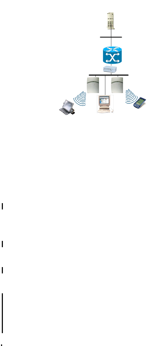
HSAAP_Intro.fm
A31003-W1110-U100-1-7619, DRAFT February 2007
HiPath Wireless Standalone Access Point V1.0, User Guide 47
About the HiPath Wireless Standalone Access Point
Standalone Access Point and your network
Figure 1 Network traffic flow diagram
For more information on the DHCP Server, refer to the HiPath Wireless documentation.
3.3.2 About network security
The Standalone Access Point provides features and functionality to control network access.
These are based on standard wireless network security practices. Current wireless network
security methods provide a degree of protection. These methods include an open system that
rely on Service Set Identifiers (SSIDs).
The Standalone Access Point supports the following encryption approaches:
●Wired Equivalent Privacy (WEP) – A security protocol for wireless local area networks
defined in the IEEE 802.11b standard that provides static key management, and WEP 40-
bit, 104-bit, and 128-bit ciphers. The WEP protocol provides minimal security.
●Wi-Fi Protected Access version 1 (WPA v.1) – A security protocol with Temporal Key
Integrity Protocol (TKIP) that provides Pre-shared Master Key management, and a WEP
128-bit cipher. The WPA v.1 protocol provides good security.
●Wi-Fi Protected Access version 2 (WPA v.2) – A security protocol with Advanced
Encryption Standard (AES) that provides Pre-shared Master Key management, and an
AES 128-bit cipher. The WPA v.2 protocol provides the best security. It is highly
recommended to use WPA v.2.
●Media Access Control address(MAC) – In addition, MAC address filters are used in
securing the network. Authentication by MAC address provides a method of access control
for a user as it associates with the access point based on the device's MAC address.
802.11 IP
packet
transmission
802.11 beacon
& probe,
wireless device
associates with
a Standalone
Access Point by
its SSID
DHCP Server
Ethernet Switch
Router
Wireless Device Wireless Device
Standalone Access
Point

About the HiPath Wireless Standalone Access Point
A31003-W1110-U100-1-7619, DRAFT February 2007
48 HiPath Wireless Standalone Access Point V1.0, User Guide
HSAAP_Intro.fm
About clustering
3.3.3 About Quality of Service
The Standalone Access Point provides advanced Quality of Service (QoS) management in
order to provide better network traffic flow. Such standards include:
●WMM (Wi-Fi Multimedia) – Enabled per VNS on the Standalone Access Point. For
devices with WMM or 802.1e enabled, the standard provides multimedia enhancements
for audio, video, and voice applications. WMM and 802.11e shorten the time between
transmitting packets for higher priority traffic.
●IP ToS (Type of Service) or DSCP (Diffserve Codepoint) – The ToS/DSCP field in the
IP header of a frame is used to indicate the priority and QoS for each frame.
●802.11e – If enabled, the Standalone Access Point will accept 802.11e client associations,
and will classify and prioritize the downlink traffic for all 802.11e clients. 802.11e clients will
also classify and prioritize the uplink traffic.
When Priority Override is enabled, the configured User Priority will determine the transmit
queue and the user priority for the wireless QoS packets (WMM or 802.11e) in the downlink
direction. The User Priority value is also used to tag the VLAN Priority field for the uplink
traffic if the VLAN tagging is enabled for this VNS.
3.4 About clustering
The Standalone Access Point must operate in cluster setup. The purpose of the cluster is to
limit the number of access points in it, and to enable roaming. Secure Inter-Access Point
Protocol (SIAPP) is used to build cluster information in each access point. All access points in
the same roaming cluster must be on the same subnet.
3.4.1 Forming a cluster
A cluster is formed when an access point is connected with one or more additional access
points. A cluster is identified by the cluster name, based on the SSID. All Standalone Access
Points within the cluster have a common cluster name. An access point can have a state of
either Master, Slave, or Register. In a cluster, one access point must be in the Master state. The
number of access points in the cluster at any time cannot be larger than ten, including the
Master and Slave state access points, and their radios are enabled. The radios are disabled for
all Register state access points.
The access point in the Master state broadcasts an update packet periodically, which contains
the list of the access points currently registered with the cluster. The first access point listed is
the Master, then the first Slave, the second Slave, and so on.

HSAAP_Installing.fm
A31003-W1110-U100-1-7619, DRAFT February 2007
HiPath Wireless Standalone Access Point V1.0, User Guide 49
Installing and configuring the Standalone Access Point
Installing a Standalone Access Point
4 Installing and configuring the Standalone Access
Point
Prior to using the Standalone Access Point, it must be properly installed and configured.
4.1 Installing a Standalone Access Point
To install the Standalone Access Point:
1. Unpack the Standalone Access Point from its shipment carton, and check that all parts are
present. For more information, see HiPath Wireless Standalone Access Point Getting
Started Guide delivered with the device.
2. Mount the wall bracket, using 3 screws, near the LAN Ethernet cable plug on the wall.
Figure 2 Wall bracket and rearview of Standalone Access Point
3. Press the back of the Standalone Access Point onto the bracket, aligning it with the open
notches in the bracket. Then slide it downward until the security spring clip holds it in place.
To remove the Standalone Access Point, release the spring clip by inserting an Allen key
(or other similar tool) into the small hole at the bottom of the bracket. Then slide the case
up the bracket and lift off the Standalone Access Point.
4. Insert the plastic spreading rivet through the hole at the bottom of the bracket and into the
Standalone Access Point case. Then screw in the plastic screw. This spreads the rivet and
locks the case to the bracket. To remove the Standalone Access Point, use a screwdriver
to remove the screw.
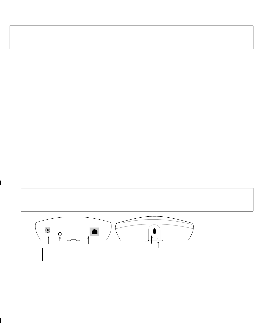
Installing and configuring the Standalone Access Point
A31003-W1110-U100-1-7619, DRAFT February 2007
50 HiPath Wireless Standalone Access Point V1.0, User Guide
HSAAP_Installing.fm
Connecting and powering the Standalone Access Point
4.2 Connecting and powering the Standalone Access Point
You can connect the LAN and power up the Standalone Access Points in one of three ways:
●Power over Ethernet (PoE) – If your network is already set up with PoE, attach the LAN
ethernet cable to the RJ45 ethernet connector at the top of the Standalone Access Point.
For this method you can use a regular Ethernet cable.
●Power over Ethernet: Adding a PoE injector – If your network is not set up with PoE, you
can provide power to the LAN ethernet cable with a PoE injector. The PoE injector must be
802.3af compliant. The PoE injector is not provided with the Standalone Access Point. If
you are using a PoE injector, refer to the manufacturer’s documentation for the necessary
requirements.
●Power by AC adaptor – An AC adaptor for the Standalone Access Point is offered
separately. The specifications are:
●Input: 120-240 VAC
●Output Voltage: DC +6V, max amps 1.50, max watts 10
If you are using a direct connection to the Standalone Access Point you must use a cross-
over Ethernet cable.
Figure 3 Top and bottom views of Standalone Access Point
7This device must not be connected to a LAN segment with outdoor wiring.
Ensure that all cables are run correctly to avoid strain. Replace the power supply
adapter immediately, if it shows any signs of damage.
>To use an adaptor, install the Standalone Access Point within six feet (two
meters) of a wall outlet, attach the adaptor to the Standalone Access Point and
then plug the adaptor into the wall outlet.
power
connector LAN Ethernet
port opening for
rivet opening for
Allen key
reset
button

HSAAP_Installing.fm
A31003-W1110-U100-1-7619, DRAFT February 2007
HiPath Wireless Standalone Access Point V1.0, User Guide 51
Installing and configuring the Standalone Access Point
Understanding Standalone Access Point LED status
4.3 Understanding Standalone Access Point LED status
The description below assumes the software uses a timer and multiple phases to simulate LED
"blinking" on all three LEDs. For example, an LED status of "Red" means that the LED is solid-
colored "Red", and an LED status of “Off/Green/Off” indicates that the LED is “Off” for the first
phase, is “Green” for the second phase, and is “Off” for the third phase.
Table 12 Standalone Access Point LED status definitions
Left LED
Status
Center
LED
Status
Right LED
Status
Access Point Status
Off Off Off Powered-off
Off Green Off Beginning of Power-On-Self-Test (POST) (0.5s)
Off Off Off POST
Off Red Off Failure during POST
Green Off Green Random delay (state shown only after a vulnerable reset)
Green/Off Off/Green Green/Off Vulnerable time interval (the Standalone Access Point
resets to factory default if powered-off for three
consecutive times during this state). No vulnerable
period when Standalone Access Point is resetting to
factory defaults.
Green/Off/
Off
Off/
Green/Off
Off/Off/
Green
Resetting to factory defaults announcement (replaces
vulnerable period). This pattern is repeated twice to
notify the operator when the factory configuration is
restored.
Off Orange
(Green +
Red)/
Green
Off Attempting to obtain IP address via DHCP
Off Off/Green Off Obtained IP address, attempting to join the cluster
Green
when
802.11b/g
enabled
Off
otherwise
Green Green when
802.11a
enabled
Off
otherwise
Member of cluster, radios enabled per user settings

Installing and configuring the Standalone Access Point
A31003-W1110-U100-1-7619, DRAFT February 2007
52 HiPath Wireless Standalone Access Point V1.0, User Guide
HSAAP_Installing.fm
Restoring the factory default settings
4.4 Restoring the factory default settings
There are three different methods for restoring the Standalone Access Point factory default
settings:
●Vulnerable time interval – The Standalone Access Point boot-up sequence includes a
vulnerable time interval. During the vulnerable time interval (2 seconds), the LEDs flash in
a particular sequence to indicate that the Standalone Access Point is in the vulnerable time
interval. For more information, see Table 12 on page 51.
If you power up the Standalone Access Point and interrupt the power during the vulnerable
time interval three consecutive times, the next time the Standalone Access Point reboots,
it will restore its factory defaults including the user password and the default IP settings.
●Reset button (Hardware) – Press and hold the Reset button on the Standalone Access
Point for approximately five seconds. The Standalone Access Point is rebooted and the
factory defaults are restored.
●Restore Factory Defaults (Graphical User Interface) – Use the Restore Factory
Defaults button on the Tools > Configuration screen to restore the factory defaults via
the Standalone Access Point GUI. For more information, see Section 6.4.3, “Restoring the
factory default settings”, on page 89.
To restore factory default settings using the vulnerable time interval:
1. Reboot the Standalone Access Point.
2. Depower and power the Standalone Access Point during the vulnerable time interval.
3. Repeat Step 2 twice.
When the Standalone Access Point reboots for the fourth time, after having its power
supply interrupted three consecutive times, it restores its factory default settings.
>Random delays do not occur during normal reboot. Random delay only occurs after
vulnerable period power-down.
>The restoration of factory default settings does not erase the non-volatile log.

HSAAP_Getting_Started.fm
A31003-W1110-U100-1-7619, DRAFT February 2007
HiPath Wireless Standalone Access Point V1.0, User Guide 53
Getting started with a Standalone Access Point
About the interface
5 Getting started with a Standalone Access Point
You access the Standalone Access Point through a Web browser.
5.1 About the interface
The Standalone Access Point supports two types of users:
●Administrator – The case-sensitive user ID is admin. The default password is admin.
●General User – The case-sensitive user ID is user. The default password is user.
There are two main states for every user:
●Logging on – The user is presented with a form that accepts their ID and password.
●Logged on – The user has access to a two-level menu that provides navigation through
the entire user interface.
If you are logged in as an Administrator, the top level menu has the following options:
●Status – Provides access to the following screens: Info, Logs, LAN, 802.11b/g, 802.11a,
Clients, and Cluster.
●Configuration – Provides access to the following screens: LAN and Wireless. The
Wireless screen provides access to one Basic configuration tab and four advanced tabs:
Filters, Advanced 802.11b/g, Advanced 802.11a, and QoS. In addition, configuration
tabs are also available for each individual VNS: General, RF, Security, and QoS.
●Tools – Provides access to the following screens: Passwords, Configuration,
Firmware/Language, and BootROM.
●Help – Provides access to online help for each user interface screen.
●Logout – Logs the current user out of the Standalone Access Point user interface.
If you are logged in as a General User, the top level menu offers the following options:
●Status – Provides access to the following screens: Info, Logs, LAN, 802.11b/g, 802.11a,
Clients, and Cluster.
●Help – Provides access to online help for each user interface screen.
●Logout – Logs the current user out of the Standalone Access Point user interface.
5.2 Logging on to the Standalone Access Point
To access the Standalone Access Point, you must log on using a valid user ID and password.
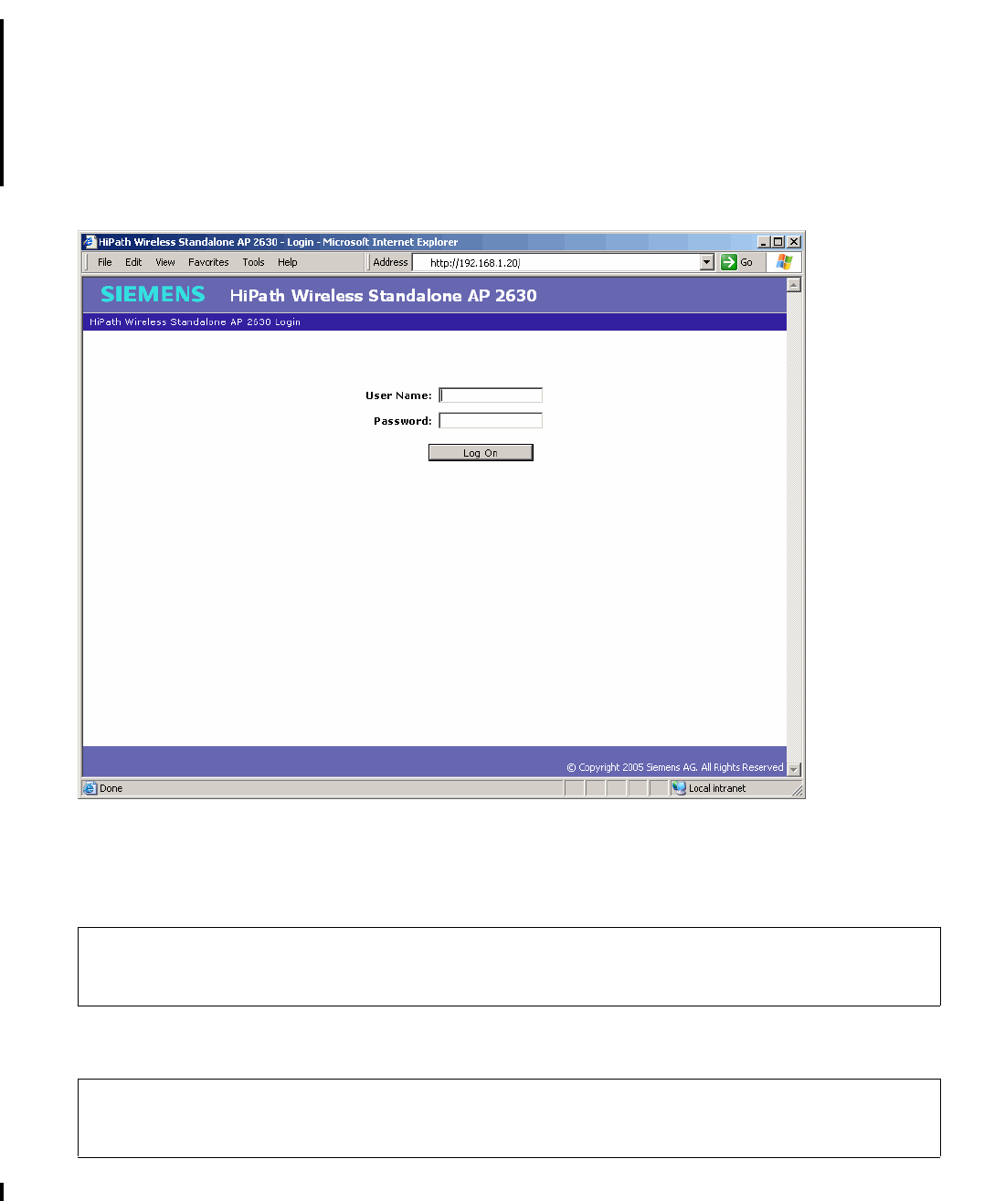
Getting started with a Standalone Access Point
A31003-W1110-U100-1-7619, DRAFT February 2007
54 HiPath Wireless Standalone Access Point V1.0, User Guide
HSAAP_Getting_Started.fm
Logging on to the Standalone Access Point
By default, the Standalone Access Point is DHCP enabled. To log on, use the IP address
according to your network DHCP IP address assignment. If the Standalone Access Point
cannot get an IP address by DHCP, use the default 192.168.1.20 IP address.
To log on to the Standalone Access Point:
1. In a Web browser, type the following:
http://192.168.1.20
2. In the User Name box, type your assigned unique user ID.
3. In the Password box, type the password corresponding to your user ID.
4. Click Log On.
>It is strongly recommended that you change your password the first time you log
on.
>The Web session will time out after 900 seconds (15 minutes) of non-activity.
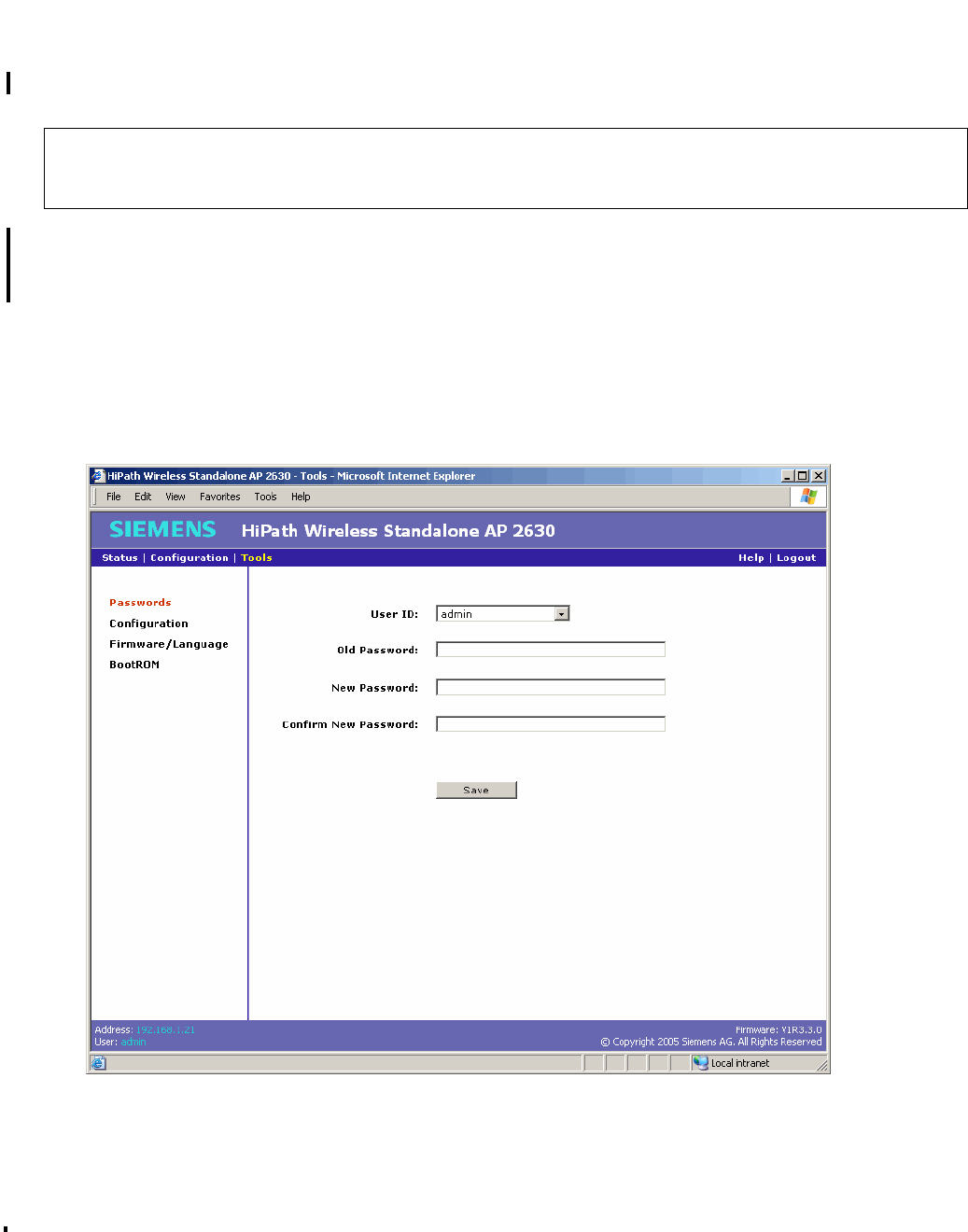
HSAAP_Getting_Started.fm
A31003-W1110-U100-1-7619, DRAFT February 2007
HiPath Wireless Standalone Access Point V1.0, User Guide 55
Getting started with a Standalone Access Point
Changing passwords
5.3 Changing passwords
Use the Passwords screen to change passwords.
The User ID drop-down list allow you to select between an Administrator or a General User. To
ensure proper security, the old password for the selected user is required to be entered
regardless of which user is logged in and which User ID is selected.
To change a password:
1. On the menu bar, click Tools.
2. In the left pane, click Passwords.
3. From the User ID drop-down list, select the user whose password you want to change.
4. In the Old Password box, type the password currently in use.
>You must have Administrator access to change a password.
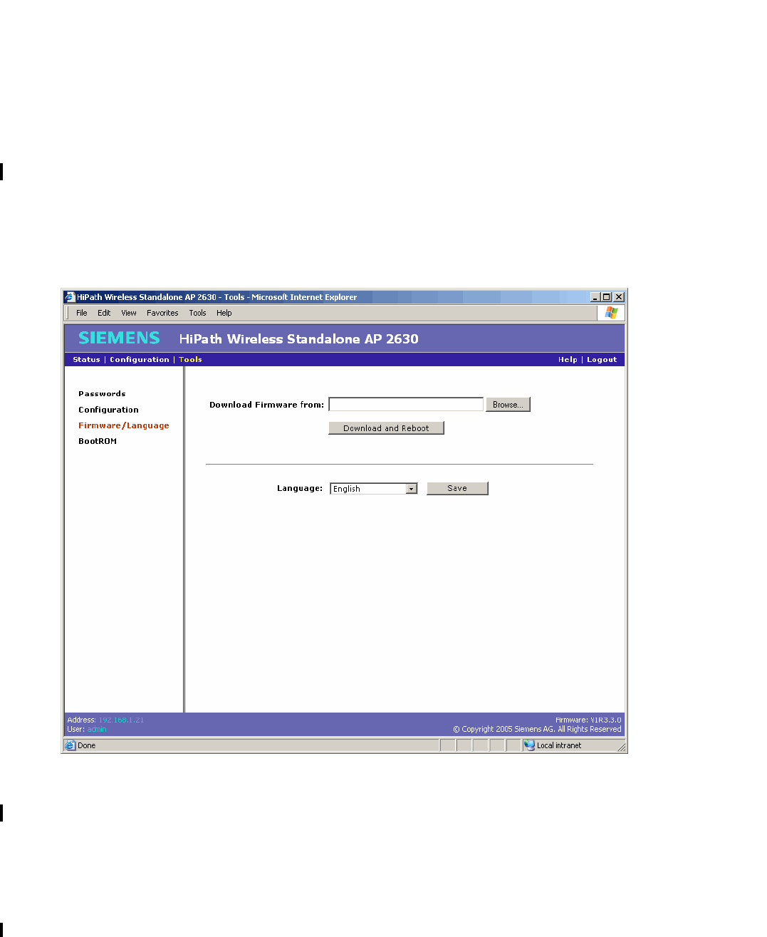
Getting started with a Standalone Access Point
A31003-W1110-U100-1-7619, DRAFT February 2007
56 HiPath Wireless Standalone Access Point V1.0, User Guide
HSAAP_Getting_Started.fm
Downloading the firmware
5. In the New Password box, type the new password.
6. In the Confirm New Password box, re-type the new password.
7. To save your changes, click Save.
5.4 Downloading the firmware
Use the Firmware/Language screen to download Standalone Access Point firmware.
To download firmware:
1. On the menu bar, click Tools.
2. In the left pane, click Firmware/Language.
3. In the Download Firmware from section, click Browse to navigate to the appropriate file.
4. Select the file to download, and then click Open in the Choose file dialog box. The
directory location is displayed in the Download Firmware from box.
5. Click Download and Reboot. The selected file is downloaded and the Standalone Access
Point is rebooted.
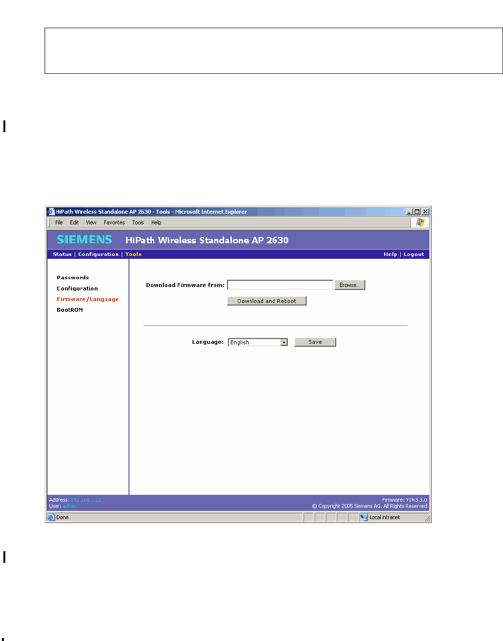
HSAAP_Getting_Started.fm
A31003-W1110-U100-1-7619, DRAFT February 2007
HiPath Wireless Standalone Access Point V1.0, User Guide 57
Getting started with a Standalone Access Point
Setting the interface language
5.5 Setting the interface language
Use the Firmware/Language screen to set the interface language.
To change the interface language setting:
1. On the menu bar, click Tools.
2. In the left pane, click Firmware/Language.
3. From the Language drop-down list, select the appropriate language for the user interface.
The available language selections are English and German. The default is English.
>The Standalone Access Point will automatically reboot using the new
downloaded firmware version. For more information, see Section 7.1,
“Rebooting”, on page 93.
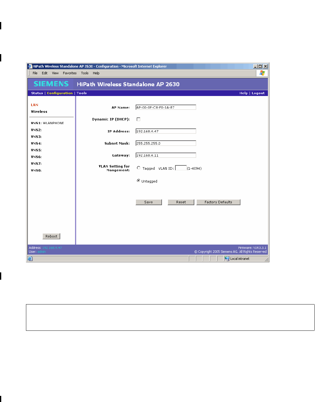
Getting started with a Standalone Access Point
A31003-W1110-U100-1-7619, DRAFT February 2007
58 HiPath Wireless Standalone Access Point V1.0, User Guide
HSAAP_Getting_Started.fm
Changing the host IP address
5.6 Changing the host IP address
Use the LAN screen to change the IP address for the Standalone Access Point.
To change the host IP address:
1. On the menu bar, click Configuration. The LAN screen is displayed.
2. In the IP Address box, type the static IP address. The default is 192.168.1.20.
3. To save your changes, click Save.
For more details on the LAN settings on this screen, see Section 6.1, “Configuring the LAN
settings”, on page 61.
>The Reboot button is available on this screen. For more information, see
Section 7.1, “Rebooting”, on page 93.
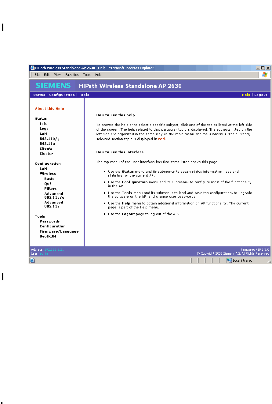
HSAAP_Getting_Started.fm
A31003-W1110-U100-1-7619, DRAFT February 2007
HiPath Wireless Standalone Access Point V1.0, User Guide 59
Getting started with a Standalone Access Point
Accessing help
5.7 Accessing help
Use the Help menu to access the online help.
To access help:
1. On the menu bar, click Help.
2. In the left pane, click the appropriate Help topic. The related Help content is displayed.

Getting started with a Standalone Access Point
A31003-W1110-U100-1-7619, DRAFT February 2007
60 HiPath Wireless Standalone Access Point V1.0, User Guide
HSAAP_Getting_Started.fm
Accessing help

HSAAP_Configuring.fm
A31003-W1110-U100-1-7619, DRAFT February 2007
HiPath Wireless Standalone Access Point V1.0, User Guide 61
Configuring a Standalone Access Point
Configuring the LAN settings
6 Configuring a Standalone Access Point
6.1 Configuring the LAN settings
Use the LAN screen to view and define the Standalone Access Point LAN configuration,
including the following:
●Access point name
●Dynamic or static IP
●Static IP settings
●VLAN Setting for Management
7Configuration changes may be delayed up to 60 seconds before being saved into the
compact flash. If power interruption occurs during that period, the configuration
changes are lost. Configuration changes will also be lost if the power for the
Standalone Access Point is reset instead of clicking the Reboot button. For more
information, see ”Rebooting”, on page 93.
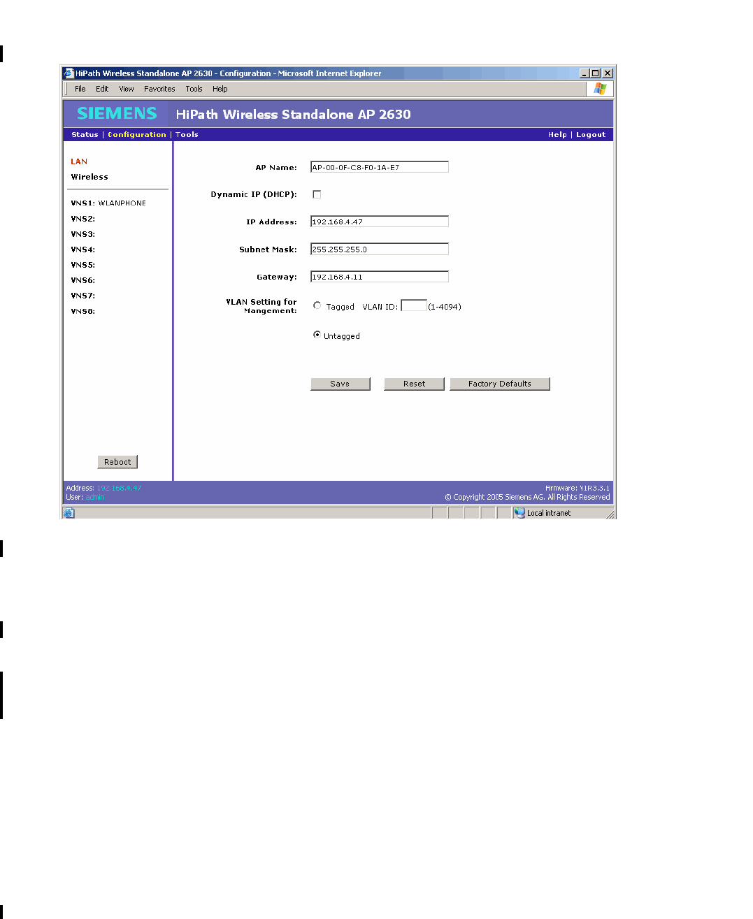
Configuring a Standalone Access Point
A31003-W1110-U100-1-7619, DRAFT February 2007
62 HiPath Wireless Standalone Access Point V1.0, User Guide
HSAAP_Configuring.fm
Configuring the LAN settings
To configure the LAN:
1. On the menu bar, click Configuration. The LAN screen is displayed.
2. In the AP Name box, type the name for the access point. The default is AP-<MAC
address>, where <MAC address> is the MAC address.
3. Do one of the following:
●To use a static IP address, clear the Dynamic IP (DHCP) check box.
●To use a dynamic IP address, select the Dynamic IP (DHCP) check box. The default
is enabled.
To use a static IP address, do the following:
●In the IP Address box, type the static IP address to be used. The default is
192.168.1.20.
●In the Subnet Mask box, type the subnet mask associated with the static IP
address to be used. The default is 255.255.255.0.
●In the Gateway box, type the gateway associated with the static IP address to be
used. The default is 192.168.1.1.

HSAAP_Configuring.fm
A31003-W1110-U100-1-7619, DRAFT February 2007
HiPath Wireless Standalone Access Point V1.0, User Guide 63
Configuring a Standalone Access Point
Configuring the wireless settings
4. For the VLAN Setting for Management options, do one of the following:
●Tagged – Select to tag all IP management packets for this Standalone Access Point.
●VLAN ID – Type the VLAN ID value you want to use as the tag.
●Untagged – Select for all IP management packets for the Standalone Access Point to
be untagged. The default is Untagged.
To enable VLAN, it is recommended that the Standalone Access Point is first connected in
an environment where there is no VLAN, enable the VLAN , and then move the Standalone
Access Point into an environment where the VLAN is required and reboot the Standalone
Access Point. The Standalone Access Point LAN configuration takes effect only after the
Standalone Access Point is rebooted and therefore the Standalone Access Point can only
be accessed in an environment having the consistent VLAN setting.
5. To save your changes, click Save.
6. To restore the settings displayed in this screen to the most recent saved values, click
Reset.
7. To restore the factory defaults for the settings on this screen, click Factory Defaults.
6.2 Configuring the wireless settings
You can configure the Standalone Access Point wireless settings. Configuring the Standalone
Access Point wireless settings includes defining the following:
●Basic settings
●Filters configuration
●802.11b/g radio settings
●802.11a radio settings
●QoS admission control thresholds
>Changing either the DHCP, IP, or VLAN settings requires a reboot of the
Standalone Access Point. The new settings only take effect after the reboot has
completed. Clicking Save will not lose the connection, but a reboot may cause
a connection loss. During the reboot, a screen will inform the you that:
The IP/VLAN setting has been changed. Please login again after the
reboot.
>The Reboot button is available on this screen. For more information, see
”Rebooting”, on page 93.
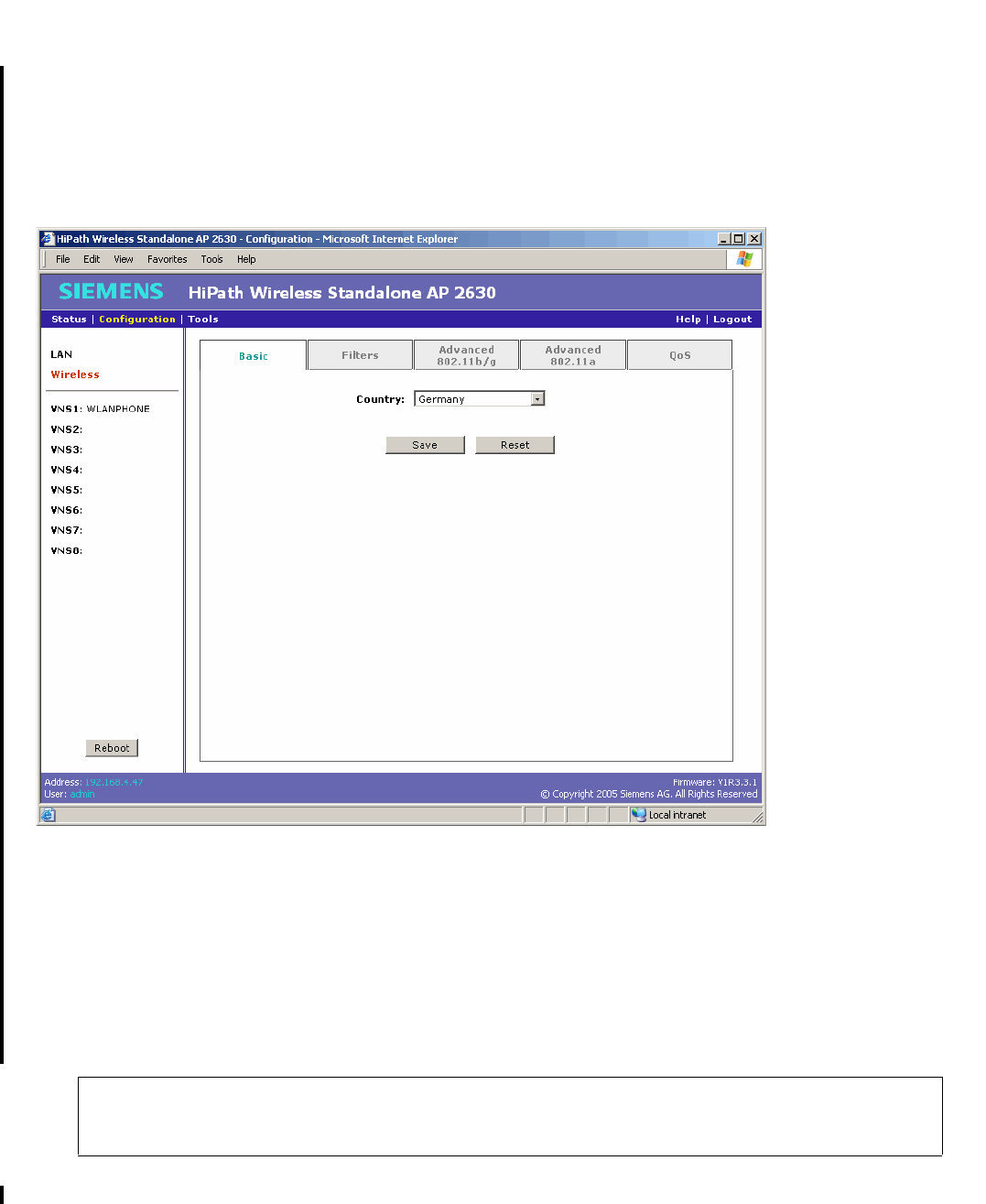
Configuring a Standalone Access Point
A31003-W1110-U100-1-7619, DRAFT February 2007
64 HiPath Wireless Standalone Access Point V1.0, User Guide
HSAAP_Configuring.fm
Configuring the wireless settings
6.2.1 Configuring the wireless basic settings
Use the Basic tab to select the country of operation for the Standalone Access Point.
To configure the wireless basic settings:
1. On the menu bar, click Configuration.
2. In the left pane, click Wireless. The Basic tab is displayed.
3. From the Country drop-down list, select the country of operation.
Selecting the correct country is essential to receiving proper service. In addition, it is illegal
to operate with the incorrect country setting.
4. To save your changes, click Save.
5. To restore the settings displayed in this screen to the most recent saved values, click
Reset.
>The Reboot button is available on this screen. For more information, see
”Rebooting”, on page 93.
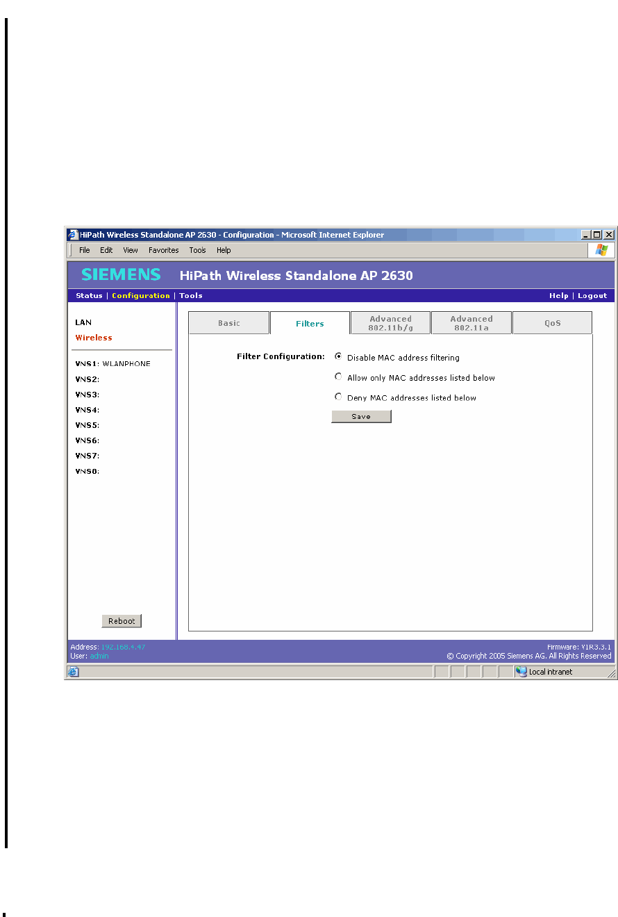
HSAAP_Configuring.fm
A31003-W1110-U100-1-7619, DRAFT February 2007
HiPath Wireless Standalone Access Point V1.0, User Guide 65
Configuring a Standalone Access Point
Configuring the wireless settings
6.2.2 Configuring the wireless filter settings
Use the Filters tab to configure client filtering based on a MAC address. The default is no MAC
address in the list and MAC address filtering is disabled.
To configure the wireless Filter settings:
1. On the menu bar, click Configuration.
2. In the left pane, click Wireless.
3. Click the Filters tab.
4. In the Filter Configuration area, do one of the following:
●Disable MAC address filtering – Select to disable filtering.
●Allow only MAC addresses listed below – Select to allow only those MAC
addresses that are listed to connect.
●Deny MAC addresses listed below – Select to deny those MAC addresses that are
listed to connect.

Configuring a Standalone Access Point
A31003-W1110-U100-1-7619, DRAFT February 2007
66 HiPath Wireless Standalone Access Point V1.0, User Guide
HSAAP_Configuring.fm
Configuring the wireless settings
5. To save your changes, click Save.
6. To create either a list of MAC addresses to allow or a list of MAC addresses to deny, type
the new MAC address in the Add MAC Address box, and then click Add. The message
Update successful is displayed. The new MAC address is displayed in the MAC Address
list when you click the applicable filter configuration option.
7. To delete MAC addresses from the list, select the Select check box for each of the MAC
addresses you want to delete, and then click Delete Selected Items. The deleted MAC
addresses will be removed from the MAC Address list.
8. To delete all MAC addresses from the list, click Delete All. All MAC addresses will be
removed from the MAC Address list.
>The Allow and Deny filters are mutually exclusive. You can create either a list of
MAC addresses to allow or a list of MAC addresses to deny. It is not possible to
maintain both lists at the same time.
>If necessary, click Reset Selections to clear all selected check boxes in the
MAC Address list.
>The Reboot button is available on this screen. For more information, see
”Rebooting”, on page 93.
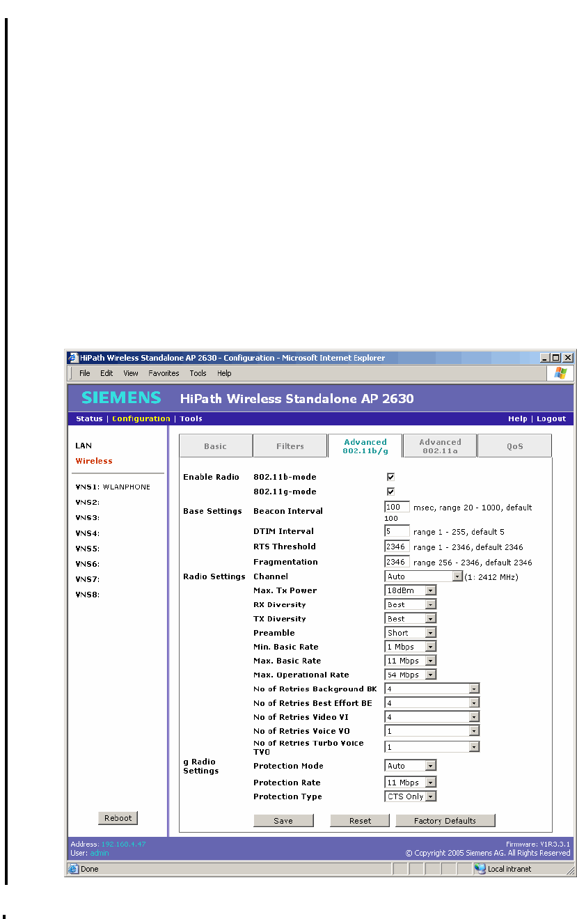
HSAAP_Configuring.fm
A31003-W1110-U100-1-7619, DRAFT February 2007
HiPath Wireless Standalone Access Point V1.0, User Guide 67
Configuring a Standalone Access Point
Configuring the wireless settings
6.2.3 Configuring the advanced 802.11b/g settings
Use the Advanced 802.11b/g tab to configure the advanced 802.11b/g radio settings,
including the following:
●Enable radio controls
●Base settings
●Radio settings
●g radio settings
To configure the 802.11b/g advanced settings:
1. On the menu bar, click Configuration.
2. In the left pane, click Wireless.
3. Click the Advanced 802.11b/g tab.

Configuring a Standalone Access Point
A31003-W1110-U100-1-7619, DRAFT February 2007
68 HiPath Wireless Standalone Access Point V1.0, User Guide
HSAAP_Configuring.fm
Configuring the wireless settings
4. In the Enable Radio section, do the following:
●802.11b – Select to enable the b/g radio for b-only mode.
●802.11g – Select to enable the b/g radio for g-only mode.
●To enable the b/g radio for mixed mode, select both the 802.11b and 802.11g check
boxes.
●To disable the b/g radio, clear both the 802.11b and 802.11g check boxes.
5. In the Base Settings section, do the following:
●Beacon Interval – Type the desired time, in milliseconds, between beacon
transmissions. The default is 100 milliseconds.
●DTIM Interval – Type the desired DTIM (Delivery Traffic Indication Map) period—the
number of beacon intervals between two DTIM beacons. To ensure the best client
power savings, use a large number. For example, 5. Use a small number to reduce
broadcast and multicast delay. The default is 5.
●RTS Threshold – Type the packet size threshold, in bytes, above which the packet will
be preceded by an RTS/CTS (Request to Send/Clear to Send) handshake. The default
is 2346, which means all packets are sent without RTS/CTS. Reduce this value only if
necessary.
●Fragmentation – Type the fragment size threshold, in bytes, above which the packets
will be fragmented by the Standalone Access Point prior to transmission. The default
is 2346, which means all packets are sent unfragmented. Reduce this value only if
necessary.
6. In the Radio Settings section, do the following:
●Channel – Select the wireless channel that the Standalone Access Point will use to
communicate with wireless devices. Depending on the regulatory domain (based on
country), some channels may be restricted. The Auto selection allows the Standalone
Access Point to select the appropriate channel automatically. If Auto is selected, the
current selected channel is displayed next to the Channel drop-down list. The default
is Auto.
●Max. Tx Power – Select the Tx power level for the Standalone Access Point: 8 through
18 dBm. The default is 18 dBm.
>Reduce the Tx Power setting if two or more neighboring access points are
operating on the same channel.

HSAAP_Configuring.fm
A31003-W1110-U100-1-7619, DRAFT February 2007
HiPath Wireless Standalone Access Point V1.0, User Guide 69
Configuring a Standalone Access Point
Configuring the wireless settings
●RX Diversity – Select Best for the best signal from both antennas, or Left or Right to
choose either of the two diversity antennas. The default and recommended selection
is Best. If only one antenna is connected, use the corresponding Left or Right
diversity setting. Do not use Best if two identical antennas are not used.
●TX Diversity – Select Best for the best signal from both antennas, or Left or Right to
choose either of the two diversity antennas. The default is Best, which maximizes
performance for most clients. However, some clients may behave oddly with Tx
Diversity set to Best. Under those circumstances, it is recommended to use either Left
or Right for Tx Diversity. If only one antenna is connected, use the corresponding Left
or Right diversity setting. Do not use Best if two identical antennas are not used.
●Preamble – Select Short to allow each packet to use less wireless bandwidth, thus
increasing overall throughput, or select Long to provide better protection. The default
is Short.
●Min. Basic Rate – Select the minimum data rate that must be supported by all stations
in a BSS: 1, 2, 5.5, or 11 Mbps for 11b and 11b+11g modes. Select 1, 2, 5.5, 6, 11,
12, or 24 Mbps for 11g-only mode. If necessary, the Max Basic Rate choices adjust
automatically to be higher or equal to the Min Basic Rate; the Max. Operational Rate
choices adjust automatically to be higher or equal to the Max. Basic Rate. If both Min
Basic Rate and Max Basic Rate are set to an 11g-specific (OFDM) rate, (for example,
6, 12, or 24 Mbps) all basic rates will be 11g-specific.
●Max. Basic Rate – Select the maximum data rate that must be supported by all
stations in a BSS: 1, 2, 5.5, or 11 Mbps for 11b and 11b+11g modes. Select 1, 2, 5.5,
6, 11, 12, or 24 Mbps for 11g-only mode. If necessary, the Max. Operational Rate
choices adjust automatically to be higher or equal to the Max Basic Rate. If both Min
Basic Rate and Max Basic Rate are set to an 11g-specific (OFDM) rate, (for example,
6, 12, or 24 Mbps) all basic rates will be 11g-specific.
●Max. Operational Rate – Select the maximum data rate that clients can operate at
while associated with the Standalone Access Point: 1, 2, 5.5, 11 Mbps for 11b-only
mode. Select 1, 2, 5.5, 6, 9, 11, 12, 18, 24, 36, 48, or 54 Mbps for 11b+11g mode and
11g-only mode. If necessary, the Max Operational Rate choices adjust automatically
to be higher or equal to the Max. Basic Rate.
●No of Retries Background BK – Select the number of retries for the Background
transmission queue. The default is 4. The recommended setting is adaptive (multi-
rate).
●No of Retries Best Effort BE – Select the number of retries for the Best Effort
transmission queue. The default is 4. The recommended setting is adaptive (multi-
rate).
●No of Retries Video VI – Select the number of retries for the Video transmission
queue. The default is 4. The recommended setting is adaptive (multi-rate).

Configuring a Standalone Access Point
A31003-W1110-U100-1-7619, DRAFT February 2007
70 HiPath Wireless Standalone Access Point V1.0, User Guide
HSAAP_Configuring.fm
Configuring the wireless settings
●No of Retries Voice VO – Select the number of retries for the Voice transmission
queue. The default is 1. The recommended setting is adaptive (multi-rate).
●No of Retries Turbo Voice TVO – Select the number of retries for the Turbo Voice
transmission queue. The default is 1. The recommended setting is adaptive (multi-
rate).
7. If the b/g radio 802.11g- mode is enabled, do the following:
●Protection Mode – Select a protection mode: None, Auto, or Always. The default and
recommended setting is Auto. Select None if 11b access points and clients are not
expected. Select Always if you expect many 11b-only clients.
●Protection Rate – Select a protection rate: 1, 2, 5.5, or 11 Mbps. The default and
recommended setting is 11 Mbps. Only reduce the rate if there are many 11b clients
in the environment or if the deployment has areas with poor coverage. For example,
rates lower than 11 Mbps are required to ensure coverage.
●Protection Type – Select a protection type: CTS Only or RTS CTS. The default and
recommended setting is CTS Only. Select RTS CTS only if an 11b access point that
operates on the same channel is detected in the neighborhood, or if there are many
11-only clients in the environment.
8. To save your changes, click Save.
9. To restore the settings displayed in this screen to the most recent saved values, click
Reset.
10. To restore the factory defaults for the settings on this screen, click Factory Defaults.
>Certain client cards or applications may require modification of the default
settings. If so, follow the manufacturer’s instructions.
>The Reboot button is available on this screen. For more information, see
”Rebooting”, on page 93.
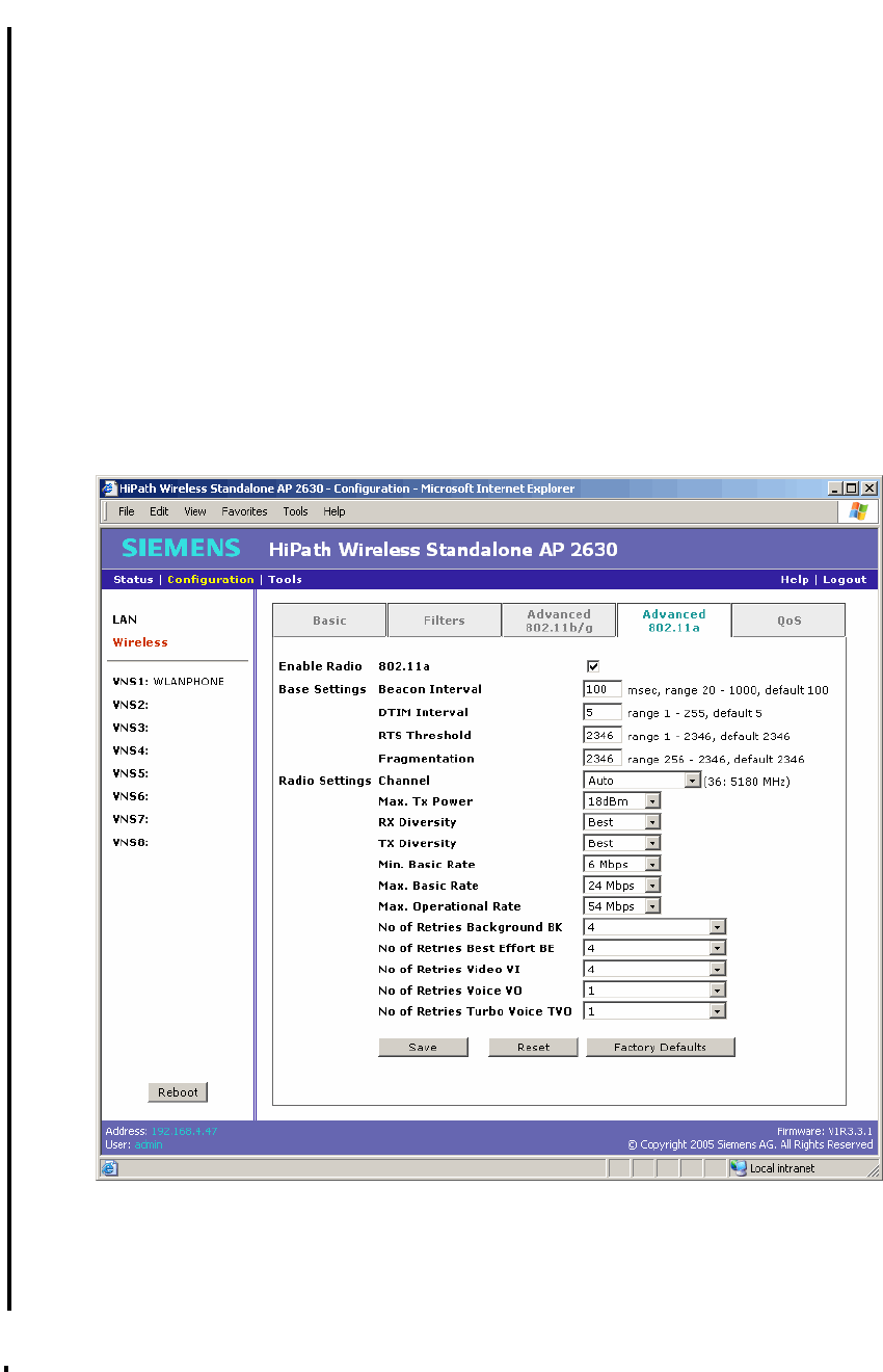
HSAAP_Configuring.fm
A31003-W1110-U100-1-7619, DRAFT February 2007
HiPath Wireless Standalone Access Point V1.0, User Guide 71
Configuring a Standalone Access Point
Configuring the wireless settings
6.2.4 Configuring the advanced 802.11a settings
Use the Advanced 802.11a tab to configure the advanced 802.11a settings, including the
following:
●Enable radio controls
●Base settings
●Radio settings
To configure the 802.11a advanced settings:
1. On the menu bar, click Configuration.
2. In the left pane, click Wireless.
3. Click the Advanced 802.11a tab.
4. In the Enable Radio section, select the 802.11a check box to enable the radio. Clear the
check box to disable the radio. The default is enabled.
5. In the Base Settings section, do the following:

Configuring a Standalone Access Point
A31003-W1110-U100-1-7619, DRAFT February 2007
72 HiPath Wireless Standalone Access Point V1.0, User Guide
HSAAP_Configuring.fm
Configuring the wireless settings
●Beacon Interval – Type the desired time, in milliseconds, between beacon
transmissions. The default is 100 milliseconds.
●DTIM Interval – Type the desired DTIM (Delivery Traffic Indication Map) period—the
number of beacon intervals between two DTIM beacons. To ensure the best client
power savings, use a large number. For example, 5. Use a small number to reduce
broadcast and multicast delay. The default is 5.
●RTS Threshold – Type the packet size threshold, in bytes, above which the packet will
be preceded by an RTS/CTS (Request to Send/Clear to Send) handshake. The default
is 2346, which means all packets are sent without RTS/CTS. Reduce this value only if
necessary.
●Fragmentation – Type the fragment size threshold, in bytes, above which the packets
will be fragmented by the Standalone Access Point prior to transmission. The default
is 2346, which means all packets are sent unfragmented. Reduce this value only if
necessary.
6. In the Radio Settings section, do the following:
●Channel – Select the wireless channel that the wireless access point will use to
communicate with wireless devices. Depending on the regulatory domain (based on
country), some channels may be restricted. The default is based on North America.
The Auto selection allows the Standalone Access Point to select the appropriate
channel automatically. If Auto is selected, the applicable channel is displayed next to
the Channel drop-down list. The default is Auto.
●Max. Tx Power – Select the Tx power level for the Standalone Access Point: 0 through
18 dBm. The default is 18 dBm.
●RX Diversity – Select Best for the best signal from both antennas, or Left or Right to
choose either of the two diversity antennas. The default and recommended selection
is Best. If only one antenna is connected, use the corresponding Left or Right
diversity setting. Do not use Best if two identical antennas are not used.
●TX Diversity – Select Best for the best signal from both antennas, or Left or Right to
choose either of the two diversity antennas. The default is Best, which maximizes
performance for most clients. However, some clients may behave oddly with Tx
Diversity set to Best. Under those circumstances, it is recommended to use either Left
or Right for Tx Diversity. If only one antenna is connected, use the corresponding Left
or Right diversity setting. Do not use Best if two identical antennas are not used.
>Reduce the Tx Power setting if two or more neighboring access points are
operating on the same channel.

HSAAP_Configuring.fm
A31003-W1110-U100-1-7619, DRAFT February 2007
HiPath Wireless Standalone Access Point V1.0, User Guide 73
Configuring a Standalone Access Point
Configuring the wireless settings
●Min. Basic Rate – Select the minimum data rate that must be supported by all stations
in a BSS: 6, 12, or 24 Mbps. If necessary, the Max Basic Rate choices adjust
automatically to be higher or equal to the Min Basic Rate; the Max. Operational Rate
choices adjust automatically to be higher or equal to the Max. Basic Rate.
●Max. Basic Rate – Select the maximum data rate that must be supported by all
stations in a BSS: 6, 12, or 24 Mbps. If necessary, the Max Basic Rate choices adjust
automatically to be higher or equal to the Min Basic Rate. If necessary, the Max.
Operational Rate choices adjust automatically to be higher or equal to the Max. Basic
Rate.
●Max. Operational Rate – Select the maximum data rate that clients can operate at
while associated with the Standalone Access Point: 6, 9, 12, 18, 24, 36, 48, or 54
Mbps. If necessary, the Max Operational Rate choices adjust automatically to be
higher or equal to the Max Basic Rate.
●No of Retries Background BK – Select the number of retries for the Background
transmission queue. The default is 4. The recommended setting is adaptive (multi-
rate).
●No of Retries Best Effort BE – Select the number of retries for the Best Effort
transmission queue. The default is 4. The recommended setting is adaptive (multi-
rate).
●No of Retries Video VI – Select the number of retries for the Video transmission
queue. The default is 4. The recommended setting is adaptive (multi-rate).
●No of Retries Voice VO – Select the number of retries for the Voice transmission
queue. The default is 1. The recommended setting is adaptive (multi-rate).
●No of Retries Turbo Voice TVO – Select the number of retries for the Turbo Voice
transmission queue. The default is 1. The recommended setting is adaptive (multi-
rate).
7. To save your changes, click Save.
8. To restore the settings displayed in this screen to the most recent saved values, click
Reset.
9. To restore the factory defaults for the settings on this tab, click Factory Defaults.
>Certain client cards or applications may require modification of the default
settings. If so, follow the manufacturer’s instructions.
>The Reboot button is available on this screen. For more information, see
”Rebooting”, on page 93.
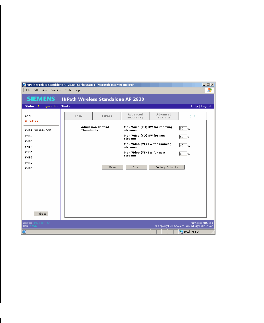
Configuring a Standalone Access Point
A31003-W1110-U100-1-7619, DRAFT February 2007
74 HiPath Wireless Standalone Access Point V1.0, User Guide
HSAAP_Configuring.fm
Configuring the wireless settings
6.2.5 Configuring the wireless Quality of Service (QoS) settings
Use the QoS tab to view and define the admission control thresholds. Admission control
thresholds protect admitted traffic against overloads, and provide distinct thresholds for VO and
VI, and distinct thresholds for roaming and new streams.
To configure the QoS settings:
1. On the menu bar, click Configuration.
2. In the left pane, click Wireless.
3. Click the QoS tab.
4. Using the Admission control thresholds drop-down lists, define the thresholds for the
following:
●Max Voice (VO) BW for roaming streams – The maximum allowed overall bandwidth
on the new Standalone Access Point when a client with an active voice stream
requests admission for the voice stream. The default is 80%.
●Max Voice (VO) BW for new streams – The maximum allowed overall bandwidth on
the Standalone Access Point when an already associated client requests admission
for a new voice stream. The default is 60%.

HSAAP_Configuring.fm
A31003-W1110-U100-1-7619, DRAFT February 2007
HiPath Wireless Standalone Access Point V1.0, User Guide 75
Configuring a Standalone Access Point
Configuring VNS for the Standalone Access Point
●Max Video (VI) BW for roaming streams – The maximum allowed overall bandwidth
on the Standalone Access Point when a client with an active video stream requests
admission for the video stream. The default is 60%.
●Max Video (VI) BW for new streams – The maximum allowed overall bandwidth on
an access point when an already associated client requests admission for a new video
stream. The default is 40%.
5. To save your changes, click Save.
6. To restore the settings displayed in this screen to the most recent saved values, click
Reset.
7. To restore the factory defaults for the settings in this tab, click Factory Defaults.
6.3 Configuring VNS for the Standalone Access Point
The Standalone Access Point can support up to 8 VNSs. For each VNS the following can be
configured:
●Radio enabling
●SSID information
●VLAN settings
●Radio frequency
●Security assignment
●Quality of service
6.3.1 Configuring the general VNS configuration
Use the General tab to configure the radio, SSID, and VLAN settings for a VNS. By default, the
SSID for the first VNS is WLANPHONE and is enabled; all other VNSs are disabled.
To configure the VNS general settings:
1. On the menu bar, click Configuration.
2. In the left pane, click the VNS you want to configure. The General tab is displayed.
>The Reboot button is available on this screen. For more information, see
”Rebooting”, on page 93.
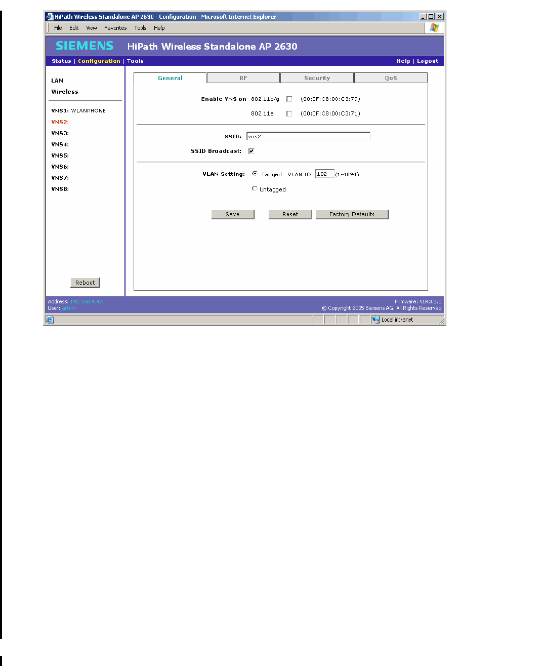
Configuring a Standalone Access Point
A31003-W1110-U100-1-7619, DRAFT February 2007
76 HiPath Wireless Standalone Access Point V1.0, User Guide
HSAAP_Configuring.fm
Configuring VNS for the Standalone Access Point
3. In the Enable VNS on section, do the following:
●802.11b/g – Select to enable the VNS on 802.11b/g radio.
●802.11a – Select to enable the VNS on 802.11a radio.
4. In the SSID box, type the name for the VNS.
5. Do one of the following:
●To enable SSID broadcasting by the Standalone Access Point, select the SSID
Broadcast check box. The default is enabled.
●To disable SSID broadcasting by the Standalone Access Point, clear the SSID
Broadcast check box.
6. For the VLAN Setting options, do one of the following:
●Tagged – Select to tag all IP packets for this VNS. The default is Tagged.
●VLAN ID – Type the VLAN ID value you want to use as the tag.
●Untagged – Select for all IP packets for the VNS to be untagged. The default is
Untagged.
By default, the first VNS is Untagged and the other VNSs are Tagged.
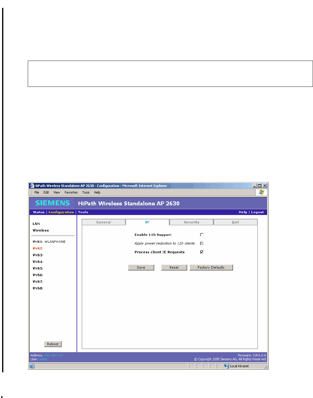
HSAAP_Configuring.fm
A31003-W1110-U100-1-7619, DRAFT February 2007
HiPath Wireless Standalone Access Point V1.0, User Guide 77
Configuring a Standalone Access Point
Configuring VNS for the Standalone Access Point
7. To save your changes, click Save.
8. To restore the settings displayed in this screen to the most recent saved values, click
Reset.
9. To restore the factory defaults for the settings on this tab, click Factory Defaults.
6.3.2 Configuring VNS radio frequency settings
Use the RF tab to configure VNS radio frequency settings.
To configure the VNS radio frequency:
1. On the menu bar, click Configuration.
2. In the left pane, click the VNS you want to configure.
3. Click the RF tab.
>The Reboot button is available on this screen. For more information, see
”Rebooting”, on page 93.

Configuring a Standalone Access Point
A31003-W1110-U100-1-7619, DRAFT February 2007
78 HiPath Wireless Standalone Access Point V1.0, User Guide
HSAAP_Configuring.fm
Configuring VNS for the Standalone Access Point
4. Do the following:
●Enable 11h Support – Select to enable 802.11h support for this VNS. The default is
disabled. It is recommended to enable this option.
●Apply power reduction to 11h clients – Select to enable the Standalone Access
Point to use reduced power (as does the 11h client) for this VNS. The default is
disabled. It is recommended to enable this option.
●Process client IE Requests – Select to enable the Standalone Access Point to accept
IE requests sent by clients via Probe Request frames and responds by including the
requested IE’s in the corresponding Probe Response frames for this VNS. The default
is enabled. It is recommended to enable this option.
5. To save your changes, click Save.
6. To restore the settings displayed in this screen to the most recent saved values, click
Reset.
7. To restore the factory defaults for the settings on this tab, click Factory Defaults.
6.3.3 Configuring VNS security settings
Use the Security tab to configure VNS security.
To configure VNS security:
1. On the menu bar, click Configuration.
2. In the left pane, click the VNS you want to configure.
3. Click the Security tab.
>The Reboot button is available on this screen. For more information, see
”Rebooting”, on page 93.
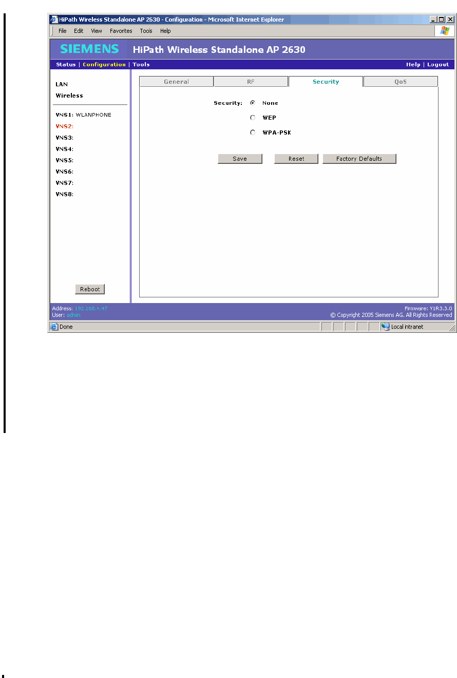
HSAAP_Configuring.fm
A31003-W1110-U100-1-7619, DRAFT February 2007
HiPath Wireless Standalone Access Point V1.0, User Guide 79
Configuring a Standalone Access Point
Configuring VNS for the Standalone Access Point
4. To configure VNS security, do one of the following:
●None – Select to disable security. The default is None.
●WEP – Select to enable WEP (Static Wired Equivalent Privacy) as the security
protocol for the VNS. WEP security selection allows the configuration of authentication
type, input method, key length, and the WEP key.
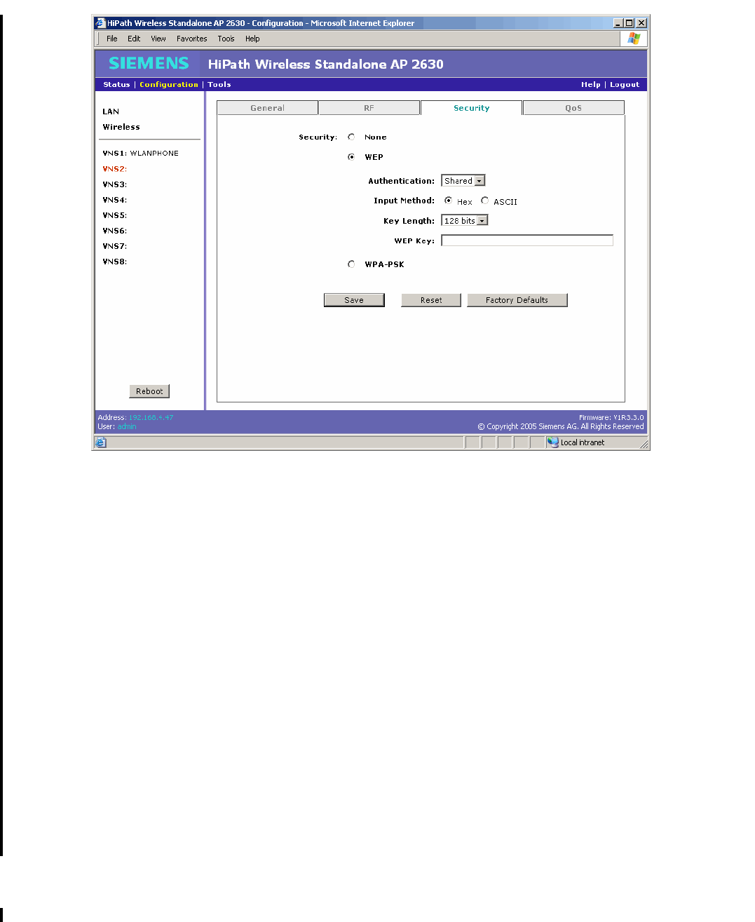
Configuring a Standalone Access Point
A31003-W1110-U100-1-7619, DRAFT February 2007
80 HiPath Wireless Standalone Access Point V1.0, User Guide
HSAAP_Configuring.fm
Configuring VNS for the Standalone Access Point
●Authentication – Select the authentication type to use. The available
authentication types are Open (no authentication), Shared (use the pre-shared
key to authenticate), and Auto (accept authentication using Open or Shared). The
default is Shared.
●To define the input method, select Hex for a hexidecimal key format or ASCII for
an ASCII key format. The default is Hex.
●Key Length – Select the length (bits) for the key. The available key lengths are 40,
104, and 128. The default is 128.
●WEP Key – Type the key. This key is verified for format and length when you save
your changes.
●WPA-PSK – Select to enable WPA-PSK (Wi-Fi Protected Access Pre-Shared key) as
the security protocol for the VNS. WPA-PSK security selection allows the configuration
of WPA v.1, WPA v.2, and the pre-shared key. You can select both WPA v.1 and WPA
v.2 to allow different clients to associate with WPA v.1 or WPA v.2.
WPA-PSK adds authentication to enhanced WEP encryption and key management.
WPA-PSK mode does not require an authentication server. It is suitable for home or
small office.
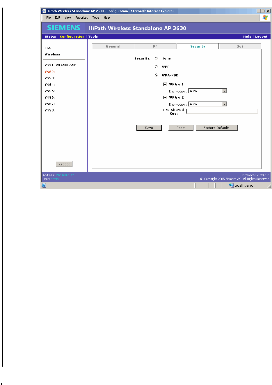
HSAAP_Configuring.fm
A31003-W1110-U100-1-7619, DRAFT February 2007
HiPath Wireless Standalone Access Point V1.0, User Guide 81
Configuring a Standalone Access Point
Configuring VNS for the Standalone Access Point
●WPA v.1 – Select to enable the pre-802.11i solution mode. The default is enabled.
●Encryption – Select the encryption type Auto or TKIP Only. The default is Auto.
If Auto is selected, the Standalone Access Point will advertise both TKIP and
CCMP (Counter Mode with Cipher Block Chaining Message Authentication Code
Protocol) for WPAv1. CCMP is an IEEE 802.11i encryption protocol that uses the
encryption cipher AES (Advanced Encryption Standard). If TKIP Only is selected,
the Standalone Access Point will advertise TKIP as an available encryption
protocol for WPAv1. It will not advertise CCMP.
●WPA v.2 – Select to enable the 802.11i solution mode. The default is enabled.
●Encryption – Select the encryption type Auto or AES Only. The default is Auto.
If Auto is selected, the Standalone Access Point will advertise both TKIP and
CCMP (Counter Mode with Cipher Block Chaining Message Authentication Code
Protocol) for WPAv2. CCMP is an IEEE 802.11i encryption protocol that uses the
encryption cipher AES (Advanced Encryption Standard). If AES Only is selected,
the Standalone Access Point will advertise AES as an available encryption
protocol for WPAv2. It will not advertise TKIP.
●Pre-shared Key – Type the ASCII password used to generate the key.
5. To save your changes, click Save.

Configuring a Standalone Access Point
A31003-W1110-U100-1-7619, DRAFT February 2007
82 HiPath Wireless Standalone Access Point V1.0, User Guide
HSAAP_Configuring.fm
Configuring VNS for the Standalone Access Point
6. To restore the settings displayed in this screen to the most recent saved values, click
Reset.
7. To restore the factory defaults for the settings on this tab, click Factory Defaults.
6.3.4 Configuring VNS QoS settings
Use the Qos tab to configure VNS QoS settings. The tab provides QoS configuration
information, including:
●WMM Priority – If enabled, the Standalone Access Point will accept WMM client
associations, and will classify and prioritize the downlink traffic for all WMM clients. WMM
clients will also classify and prioritize the uplink traffic.
●802.11e – If enabled, the Standalone Access Point will accept 802.11e client associations,
and will classify and prioritize the downlink traffic for all 802.11e clients. 802.11e clients will
also classify and prioritize the uplink traffic. WMM is the pre-802.11e standard established
by the WiFi alliance.
●Legacy – If enabled, the Standalone Access Point will classify and prioritize the downlink
traffic for all clients according to the same rules used for the WMM and 802.11e.
●Turbo Voice – If any of the above QoS modes are enabled, the Turbo Voice mode is
available. If enabled, all all downlink traffic that is classified to the Voice (VO) AC and
belongs to that VNS to be transmitted by the Standalone Access Point via a queue called
Turbo Voice (TVO) instead of the normal Voice (VO) queue. When Turbo Voice is enabled
together with WMM or 802.11e, the WMM and/or 802.11e clients in that VNS are instructed
by the Standalone Access Point to transmit all traffic classified to VO AC with special
contention parameters tailored to maximize voice performance and capacity.
To configure VNS QoS:
1. On the menu bar, click Configuration.
2. In the left pane, click the VNS you want to configure.
3. Click the QoS tab.
>The Reboot button is available on this screen. For more information, see
”Rebooting”, on page 93.
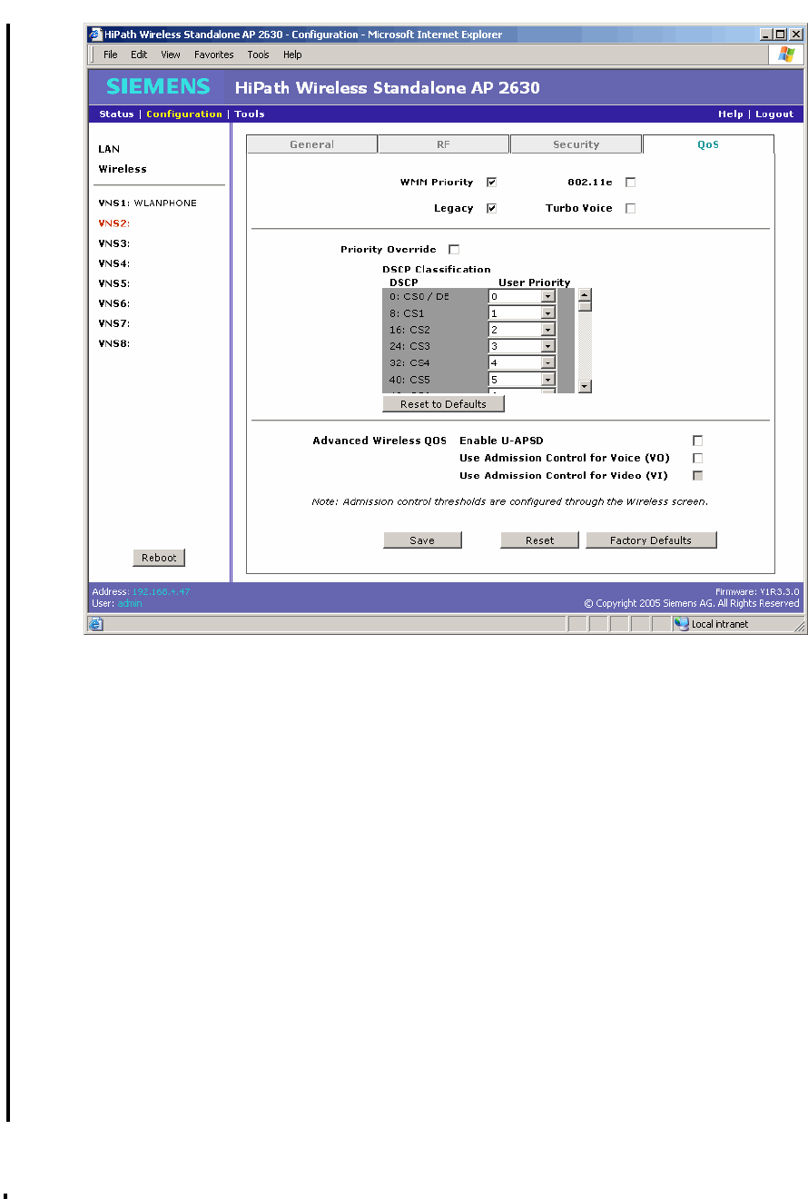
HSAAP_Configuring.fm
A31003-W1110-U100-1-7619, DRAFT February 2007
HiPath Wireless Standalone Access Point V1.0, User Guide 83
Configuring a Standalone Access Point
Configuring VNS for the Standalone Access Point
4. Do the following:
●WMM Priority – Select to enable the Standalone Access Point to accept WMM client
associations, and classify and prioritize the downlink traffic for all WMM clients. WMM
clients will also classify and prioritize the uplink traffic. WMM is part of the 802.11e
standard for QoS. If selected, the Turbo Voice option is available.
●Legacy – Select if your VNS will support legacy devices that do not support WMM or
802.11e for prioritizing voice traffic. If selected, the Turbo Voice option is available.
●802.11e – Select to enable the Standalone Access Point to accept 802.11e client
associations, and classify and prioritize the downlink traffic for all 802.11e clients. The
802.11e clients will also classify and prioritize the uplink traffic. If selected, the Turbo
Voice option is available.
●Turbo Voice – Select to enable all downlink traffic that is classified to the Voice (VO)
AC and belongs to that VNS to be transmitted by the Standalone Access Point via a
queue called Turbo Voice (TVO) instead of the normal Voice (VO) queue. When Turbo
Voice is enabled together with WMM or 802.11e, the WMM and/or 802.11e clients in
that VNS are instructed by the Standalone Access Point to transmit all traffic classified

Configuring a Standalone Access Point
A31003-W1110-U100-1-7619, DRAFT February 2007
84 HiPath Wireless Standalone Access Point V1.0, User Guide
HSAAP_Configuring.fm
Configuring VNS for the Standalone Access Point
to VO AC with special contention parameters tailored to maximize voice performance
and capacity. The Turbo Voice option is only available if either of the WMM, 802.11e,
or Legacy options are selected.
5. Do one of the following:
●To define the priority level for the VNS, select the Priority Override checkbox. The
User Priority drop-down list is displayed. From the User Priority drop-down list,
select the appropriate priority level. You can select one of the eight priority levels:
●7, 6 – Voice Traffic.
●5, 4 – Video Traffic
●3, 0 – Best Effort
●2, 1 – Background Traffic
●If you want to assign a priority level to each DSCP marking, clear the Priority Override
checkbox and define the DSCP service class priorities in the DSCP Classification
table.
Use the DSCP Classification table to classify downlink traffic by mapping the IP
DSCP to the specific User Priority that is defined for each IP DSCP value. However,
when Priority Override is enabled, the configured User Priority will be used instead.
The final User Priority will determine the transmit queue and the user priority for the
wireless QoS packets (WMM or 802.11e) in the downlink direction. The User Priority
value is also used to tag the VLAN Priority field for the uplink traffic if the VLAN tagging
is enabled for this VNS. The Standalone Access Point does not override the DSCP in
the IP header of the user packet in either the downlink or the uplink direction.

HSAAP_Configuring.fm
A31003-W1110-U100-1-7619, DRAFT February 2007
HiPath Wireless Standalone Access Point V1.0, User Guide 85
Configuring a Standalone Access Point
Configuring VNS for the Standalone Access Point
6. The Advanced Wireless QoS options are only displayed if the WMM Priority or 802.11e
checkboxes are selected:
●Enable U-APSD – Select to enable the Unscheduled Automatic Power Save Delivery
(U-APSD) feature. This feature can be used by mobile devices to efficiently sustain
one or more real-time streams while being in power-save mode. This feature works in
conjunction with WMM and/or 802.11e, and it is automatically disabled if both WMM
and 802.11e are disabled.
●Use Global Admission Control for Voice (VO) – Select to enable admission control
for Voice. With admission control, clients are forced to request admission in order to
use the high priority access categories in both downlink and uplink direction.
Admission control protects admitted traffic against new bandwidth demands.
●Use Global Admission Control for Video (VI) – This feature is only available if
admission control is enabled for Voice. Select to enable admission control for Video.
With admission control, clients are forced to request admission in order to use the high
priority access categories in both downlink and uplink direction. Admission control
protects admitted traffic against new bandwidth demands.
7. To save your changes, click Save.
8. To restore the settings displayed in this screen to the most recent saved values, click
Reset.
9. To restore the factory defaults for the settings on this tab, click Factory Defaults.
>The Reboot button is available on this screen. For more information, see
”Rebooting”, on page 93.

Configuring a Standalone Access Point
A31003-W1110-U100-1-7619, DRAFT February 2007
86 HiPath Wireless Standalone Access Point V1.0, User Guide
HSAAP_Configuring.fm
Configuring VNS for the Standalone Access Point
The following table provides detailed information on setting the QoS feature.
Table 13 Setting QoS Classification
Classification Mode
WMM
Priority
support
Legacy
Priority
support
WMM or
802.11e
client
Non-WMM/
Non-802.11e
client
Disable Disable No No All the clients will be associated as non-
QoS enable. All the Tx frames will be
assigned to AC_BE and sent without a
IEEE 802.11 QoS control header.
Enable Disable Yes No The WMM or 802.11e client will be
associated as QoS enabled. Each Tx
frame will be properly classified and
assigned to the appropriate queue. The
frame will be sent with QoS control
header. For the non-WMM/802.11e client,
the Tx frame will not be classified and will
be sent via AC_BE without a QoS control
field.
Disable Enable N/A Yes All the clients will be associated as non-
QoS enable. Each Tx frame will be
properly classified and assigned to the
appropriate queue. The frame will be sent
without a QoS control header.
Enable Enable Yes Yes The WMM or 802.11e client will be
associated as QoS enabled. Each Tx
frame will be properly classified and
assigned to the appropriate queue. The
frame will be sent with/without a QoS
control header depending upon whether
the client is associated with QoS enable or
not.
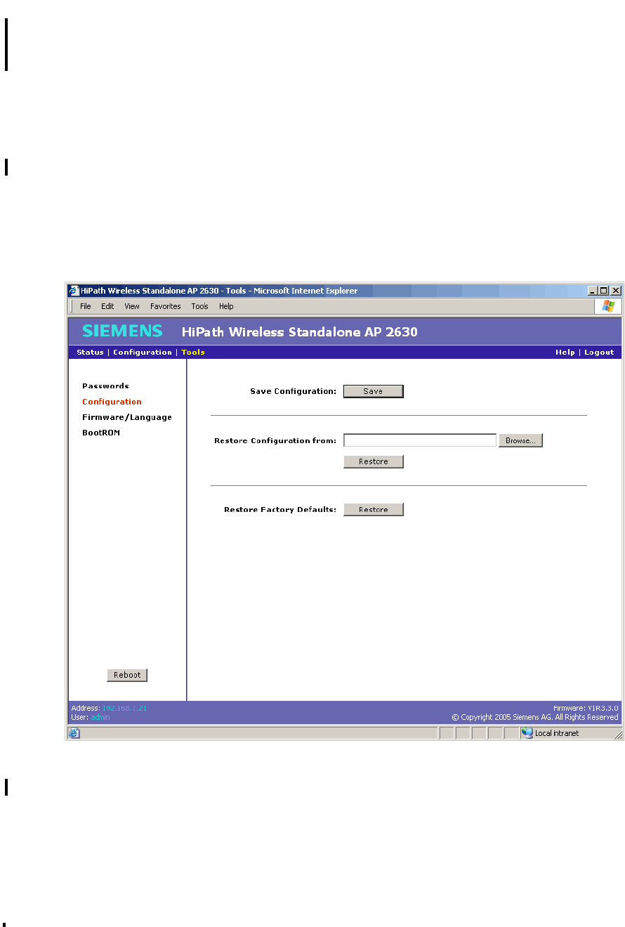
HSAAP_Configuring.fm
A31003-W1110-U100-1-7619, DRAFT February 2007
HiPath Wireless Standalone Access Point V1.0, User Guide 87
Configuring a Standalone Access Point
Managing configuration
6.4 Managing configuration
The Standalone Access Point allows you to save Standalone Access Point configurations and
then restore them at a later time. You can also restore factory default settings.
6.4.1 Saving a configuration
Use the Configuration screen to save a Standalone Access Point configuration to a file.
To save a configuration:
1. On the menu bar, click Tools.
2. In the left pane, click Configuration.
3. To save the current configuration, click Save in the Save Configuration section. The File
Download dialog box is displayed.
4. In the File Download dialog box, click Save.
5. In the Save As dialog box, navigate to a directory location.
6. In the File name box, type the name for the configuration (.cfg) file.
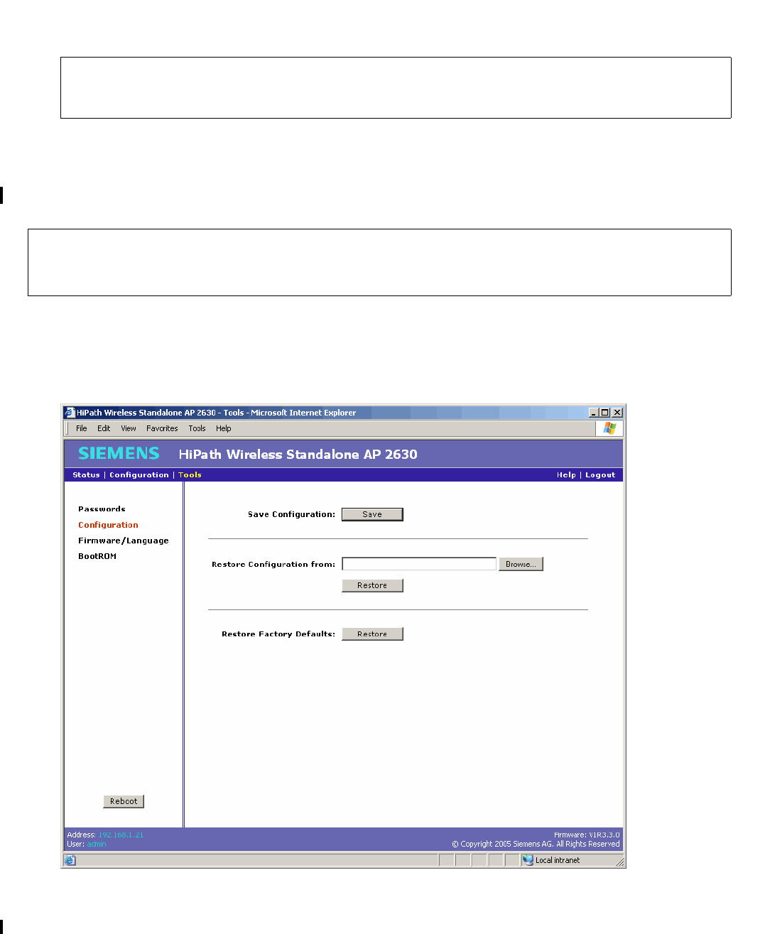
Configuring a Standalone Access Point
A31003-W1110-U100-1-7619, DRAFT February 2007
88 HiPath Wireless Standalone Access Point V1.0, User Guide
HSAAP_Configuring.fm
Managing configuration
7. To save the configuration file in the selected directory location, click Save.
6.4.2 Restoring a configuration
Use the Configuration screen to restore a Standalone Access Point configuration from a file.
To restore a configuration:
1. On the menu bar, click Tools.
2. In the left pane, click Configuration.
>The Reboot button is available on this screen. For more information, see
”Rebooting”, on page 93.
>When the configuration is restored, the software first resets all configuration
parameters to manufacturing default settings. Then the software applies the
commands in the specified configuration file.

HSAAP_Configuring.fm
A31003-W1110-U100-1-7619, DRAFT February 2007
HiPath Wireless Standalone Access Point V1.0, User Guide 89
Configuring a Standalone Access Point
Managing configuration
3. In the Restore Configuration from section, click Browse to navigate to the appropriate
configuration file.
4. Select the file to download, and then click Open in the Choose file dialog box. The
directory location is displayed in the Restore Configuration from box.
5. In the Restore Configuration from section, click Restore.
6.4.3 Restoring the factory default settings
Use the Configuration screen to restore all Standalone Access Point settings to the factory
defaults.
To restore all factory default settings:
1. On the menu bar, click Tools.
2. In the left pane, click Configuration.
>The Standalone Access Point will automatically reboot after restoring a
configuration. For more information, see ”Rebooting”, on page 93.
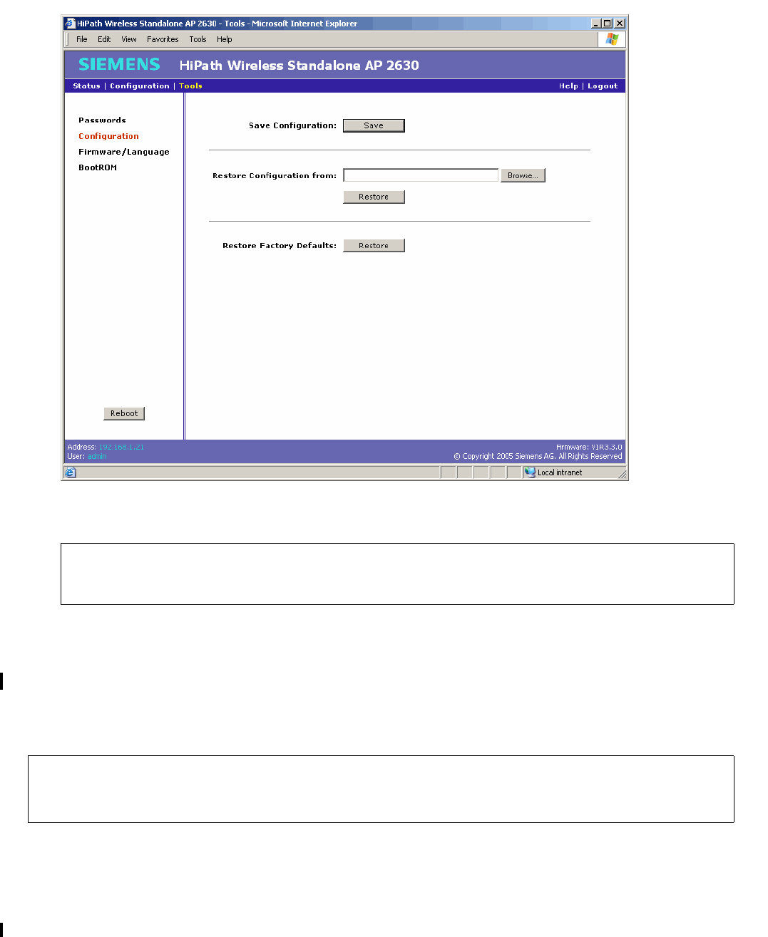
Configuring a Standalone Access Point
A31003-W1110-U100-1-7619, DRAFT February 2007
90 HiPath Wireless Standalone Access Point V1.0, User Guide
HSAAP_Configuring.fm
Managing configuration
3. In the Restore Factory Defaults section, click Restore.
6.4.4 Upgrading the BootROM
Use the BootROM screen to upgrade the BootROM. You can enter or select a path on the host
running the Web client from which to download the new BootROM. The new BootROM is
installed over the existing BootROM.
>The Standalone Access Point will automatically reboot after restoring all factory
default settings. For more information, see ”Rebooting”, on page 93.
7Upgrading the BootROM is an extremely dangerous operation. If the upgrade fails
for any reason, such as a power outage or an incorrect file, the unit requires factory
services.
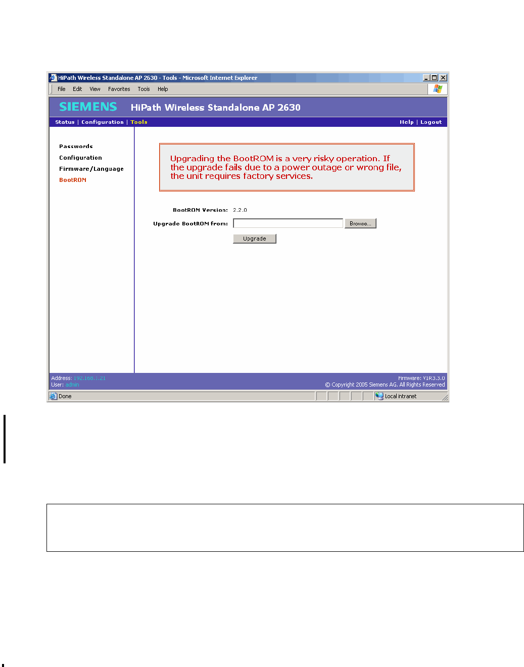
HSAAP_Configuring.fm
A31003-W1110-U100-1-7619, DRAFT February 2007
HiPath Wireless Standalone Access Point V1.0, User Guide 91
Configuring a Standalone Access Point
Managing configuration
To upgrade the BootROM:
1. On the menu bar, click Tools.
2. In the left pane, click BootROM.
3. In the Upgrade BootROM from section, click Browse to navigate to the appropriate file.
4. Select the file to download, and then click Open in the Choose file dialog box. The
directory location is displayed in the Upgrade BootROM from box.
5. Click Upgrade. The selected file is downloaded.
>The Standalone Access Point will automatically reboot using the new
downloaded BootROM version after the new BootROM is downloaded. For more
information, see ”Rebooting”, on page 93.

Configuring a Standalone Access Point
A31003-W1110-U100-1-7619, DRAFT February 2007
92 HiPath Wireless Standalone Access Point V1.0, User Guide
HSAAP_Configuring.fm
Managing configuration
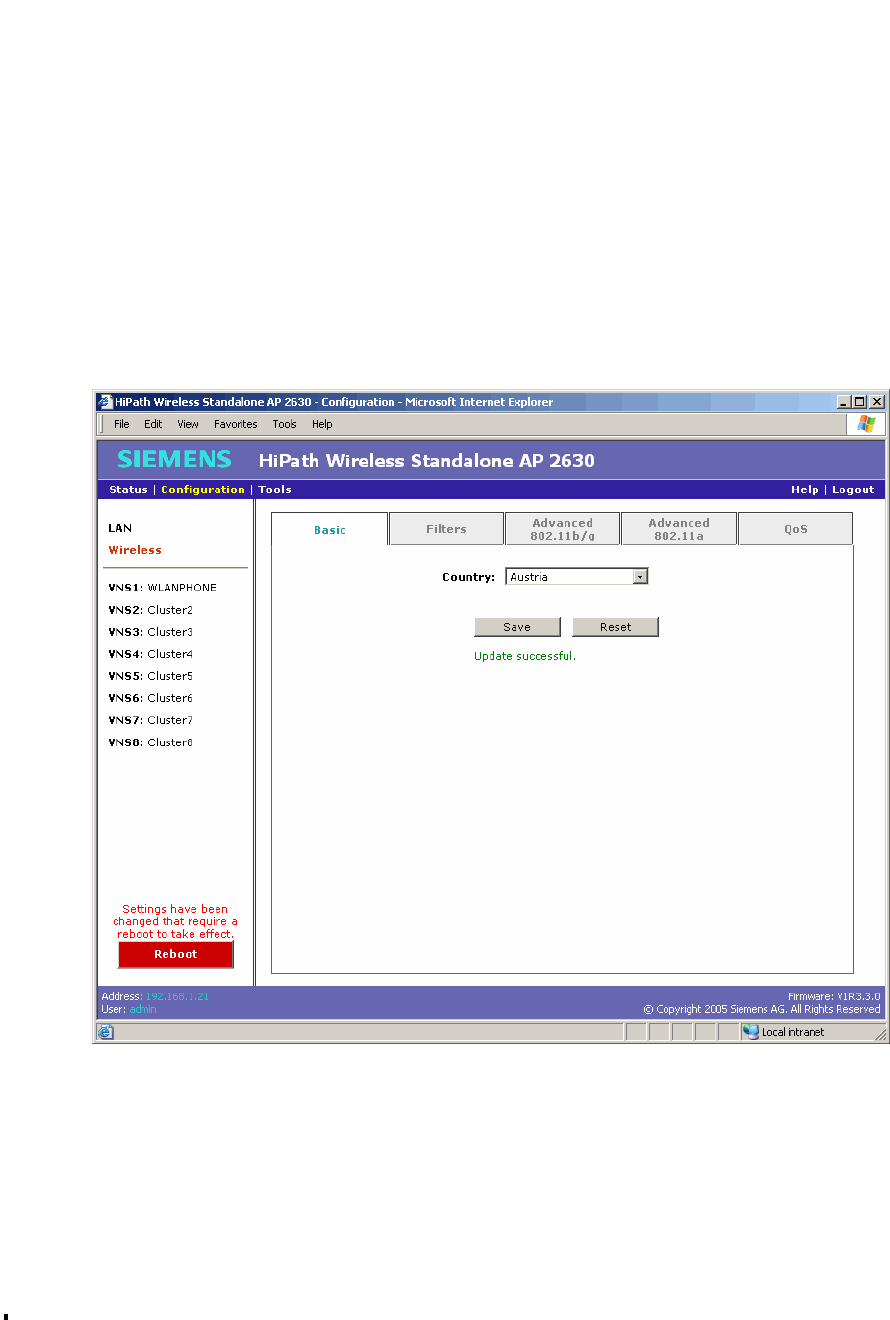
HSAAP_Troubleshooting.fm
A31003-W1110-U100-1-7619, DRAFT February 2007
HiPath Wireless Standalone Access Point V1.0, User Guide 93
Troubleshooting the Standalone Access Point
Rebooting
7 Troubleshooting the Standalone Access Point
7.1 Rebooting
You can click Reboot to restart the Standalone Access Point. Whenever the configuration has
been changed and a reboot is required, the Reboot button changes from grey to red and
displays the following message:
Settings have been changed that require a reboot to take effect.
To reboot the Standalone Access Point:
1. In the left pane, click Reboot. The Standalone Access Point is rebooted.
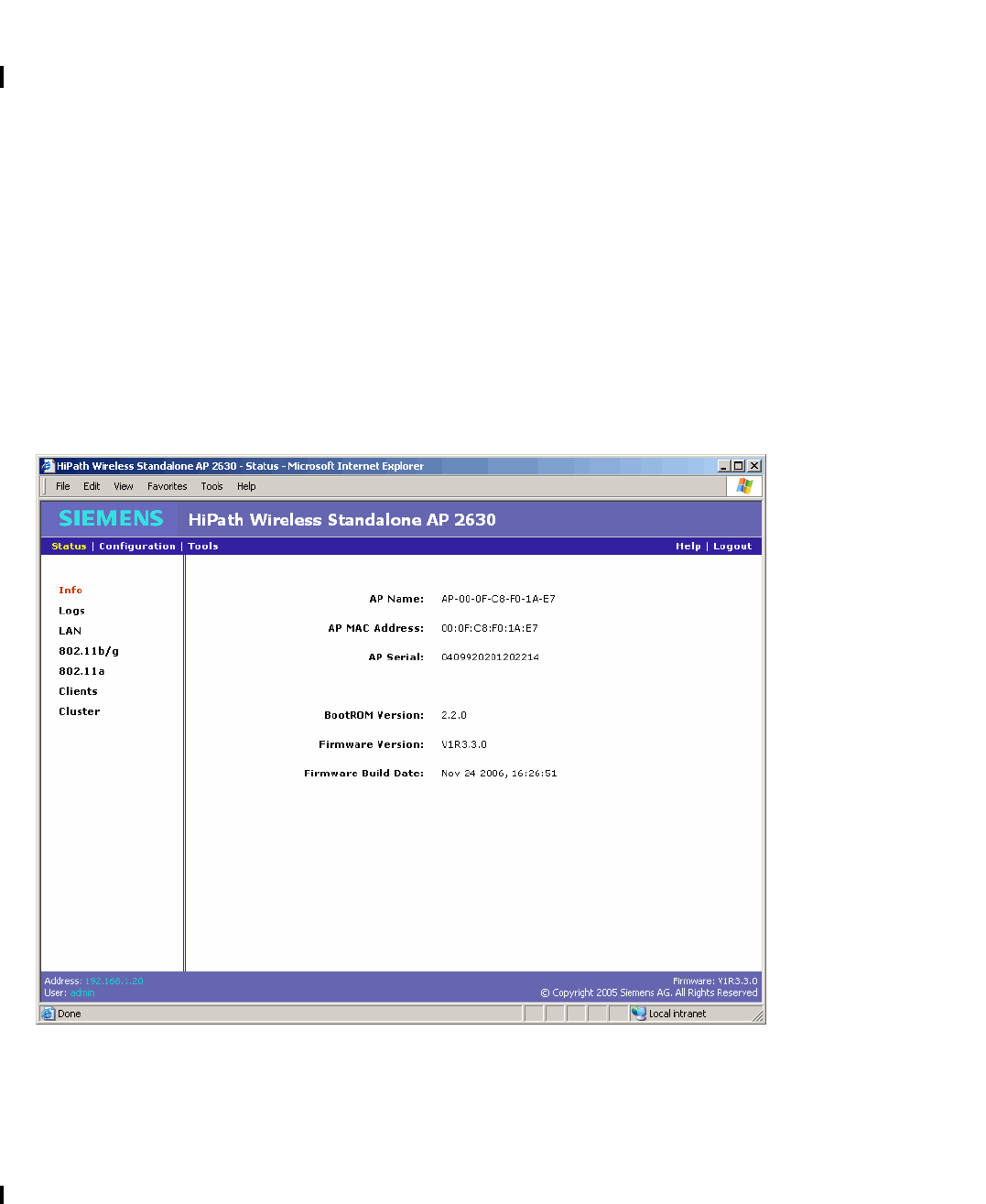
Troubleshooting the Standalone Access Point
A31003-W1110-U100-1-7619, DRAFT February 2007
94 HiPath Wireless Standalone Access Point V1.0, User Guide
HSAAP_Troubleshooting.fm
Viewing status information
7.2 Viewing status information
Use the Info screen to view Standalone Access Point system status information. The screen
displays the following:
●Access point name
●Access point MAC address
●Access point serial number
●BootROM version
●Firmware version
●Firmware build date
To view system status information:
On the menu bar, click Status. The Info screen is displayed.

HSAAP_Troubleshooting.fm
A31003-W1110-U100-1-7619, DRAFT February 2007
HiPath Wireless Standalone Access Point V1.0, User Guide 95
Troubleshooting the Standalone Access Point
Viewing log status information
7.3 Viewing log status information
Use the Logs screen to view Standalone Access Point log status information. The screen
displays the contents of the flash-based log file in an easy-to-read format. Each log entry is
displayed on a separate line. You can view the following log status information:
●A unique session number, incremented on every reboot of the Standalone Access Point.
This number wraps at 255.
●The timestamp within the session, displayed in days, hours, minutes and seconds since the
session started.
●An event code.
●A log message event description containing text and optional parameters. For example,
MAC and IP addresses.
For more information, see Appendix A, “Appendix: Log codes and messages”.
To view log status information:
1. On the menu bar, click Status.
2. In the left pane, click Logs.
>The log displays only the last 50 events.
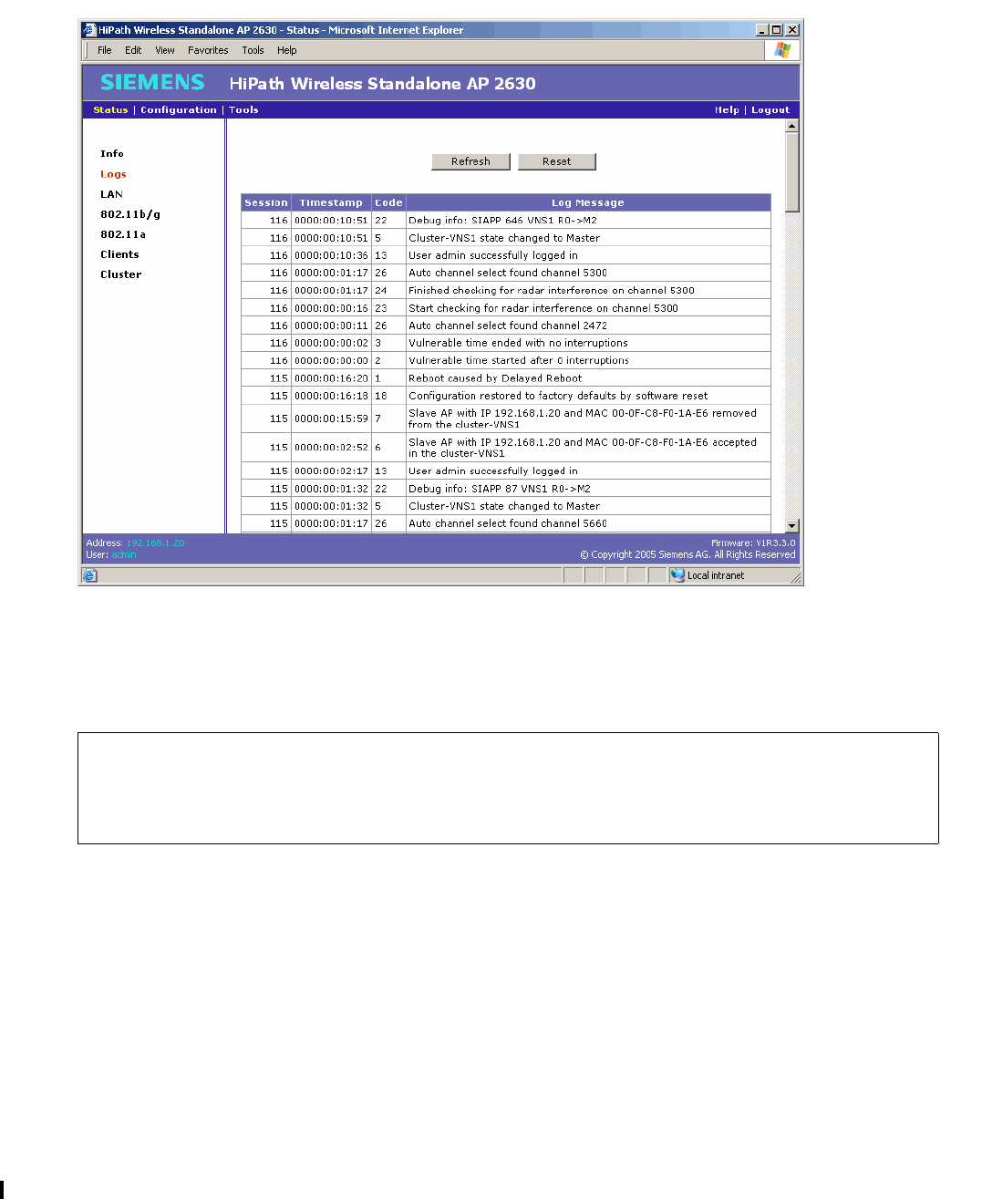
Troubleshooting the Standalone Access Point
A31003-W1110-U100-1-7619, DRAFT February 2007
96 HiPath Wireless Standalone Access Point V1.0, User Guide
HSAAP_Troubleshooting.fm
Viewing log status information
3. To update the log data displayed to the most current data, click Refresh.
4. To clear all entries from the log, click Reset. This button is disabled for users with read-only
privileges.
>Restoring the factory default settings by either hardware or software does not
clear the log. Both events are recorded in the log using different codes. For more
information, see 3.1"Resetting to factory default settings" on page 15 or
5.2.3"Restoring the factory default settings" on page 41.
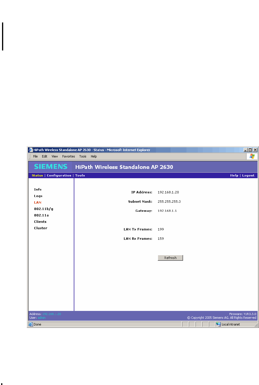
HSAAP_Troubleshooting.fm
A31003-W1110-U100-1-7619, DRAFT February 2007
HiPath Wireless Standalone Access Point V1.0, User Guide 97
Troubleshooting the Standalone Access Point
Viewing LAN status information
7.4 Viewing LAN status information
Use the LAN screen to view Standalone Access Point LAN status information. The screen
displays the following:
●IP address
●Subnet mask
●Gateway
●Number of LAN Tx frames
●Number of LAN Rx frames
To view the LAN status information:
1. On the menu bar, click Status.
2. In the left pane, click LAN.
3. To update the LAN data displayed to the most current data, click Refresh.
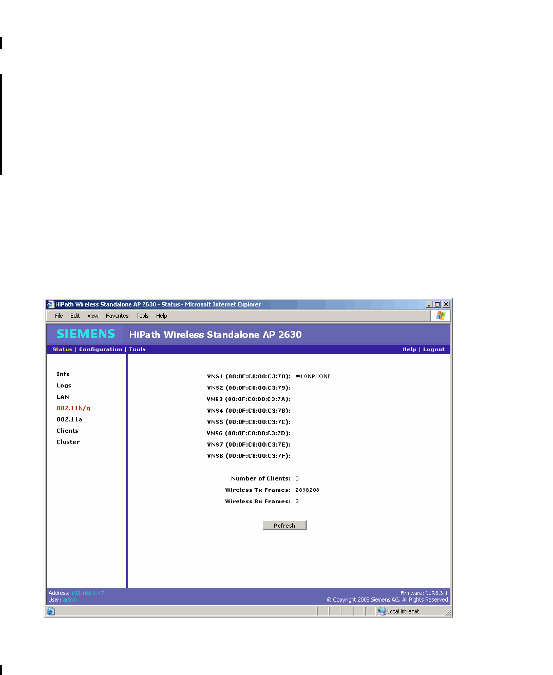
Troubleshooting the Standalone Access Point
A31003-W1110-U100-1-7619, DRAFT February 2007
98 HiPath Wireless Standalone Access Point V1.0, User Guide
HSAAP_Troubleshooting.fm
Viewing 802.11b/g status information
7.5 Viewing 802.11b/g status information
Use the 802.11b/g screen to view the Standalone Access Point 802.11b/g status information.
The screen displays the following:
●Radio status of the VNS. Note that if the Standalone Access Point is not in the cluster, the
radio will always be disabled. BSSID – A 48bit identifier used to identify a particular BSS
(Basic Service Set) is always displayed. For each enabled VNS, the SSID name is
displayed.
●VNS (SSID) name and status
●Number of clients currently associated with this Standalone Access Point on this radio
●Number of wireless Tx frames
●Number of wireless Rx frames
To view the 802.11b/g status information:
1. On the menu bar, click Status.
2. In the left pane, click 802.11b/g.
3. To update the data displayed to the most current data, click Refresh.
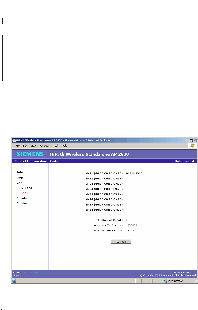
HSAAP_Troubleshooting.fm
A31003-W1110-U100-1-7619, DRAFT February 2007
HiPath Wireless Standalone Access Point V1.0, User Guide 99
Troubleshooting the Standalone Access Point
Viewing 802.11a status information
7.6 Viewing 802.11a status information
Use the 802.11a screen to view the Standalone Access Point 802.11a status information. The
screen displays the following:
●Radio status of the VNS. Note that if the Standalone Access Point is not in the cluster, the
radio will always be disabled. BSSID – A 48bit identifier used to identify a particular BSS
(Basic Service Set) is always displayed. For each enabled VNS, the SSID name is
displayed.
●VNS (SSID) name and status
●Number of clients currently associated with this Standalone Access Point on this radio
●Number of wireless Tx frames
●Number of wireless Rx frames
To view the 802.11a status information:
1. On the menu bar, click Status.
2. In the left pane, click 802.11a.
3. To update the data displayed to the most current data, click Refresh.
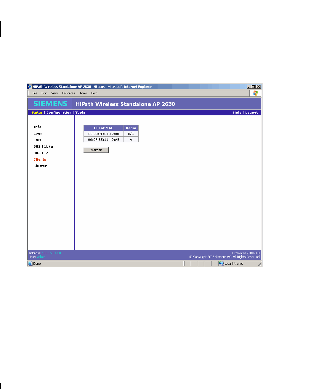
Troubleshooting the Standalone Access Point
A31003-W1110-U100-1-7619, DRAFT February 2007
100 HiPath Wireless Standalone Access Point V1.0, User Guide
HSAAP_Troubleshooting.fm
Viewing the client status information
7.7 Viewing the client status information
Use the Clients screen to view the Standalone Access Point client status information. The
screen displays the MAC address of the client and the radio being used.
To view the client status information:
1. On the menu bar, click Status.
2. In the left pane, click Clients.
3. To update the client data displayed to the most current data, click Refresh.

HSAAP_Troubleshooting.fm
A31003-W1110-U100-1-7619, DRAFT February 2007
HiPath Wireless Standalone Access Point V1.0, User Guide 101
Troubleshooting the Standalone Access Point
Viewing the cluster status information
7.8 Viewing the cluster status information
Use the Cluster screen to view the Standalone Access Point cluster information. The screen
displays the list of Standalone Access Points that are currently registered in the cluster. For
each enabled VNS, the SSID name is displayed in the drop-down list. Each Standalone Access
Point is displayed showing the following:
●Rank within the cluster
●IP address
●MAC address
●Name
●Number of clients currently associated with the Standalone Access Point
The Standalone Access Points are listed in their ranking order. For more information, see
3.4"About clustering", on page 48. If the current Standalone Access Point is not part of the
cluster, the screen lists the cluster without the current Standalone Access Point.
To view the cluster status information:
1. On the menu bar, click Status.
2. In the left pane, click Clusters.
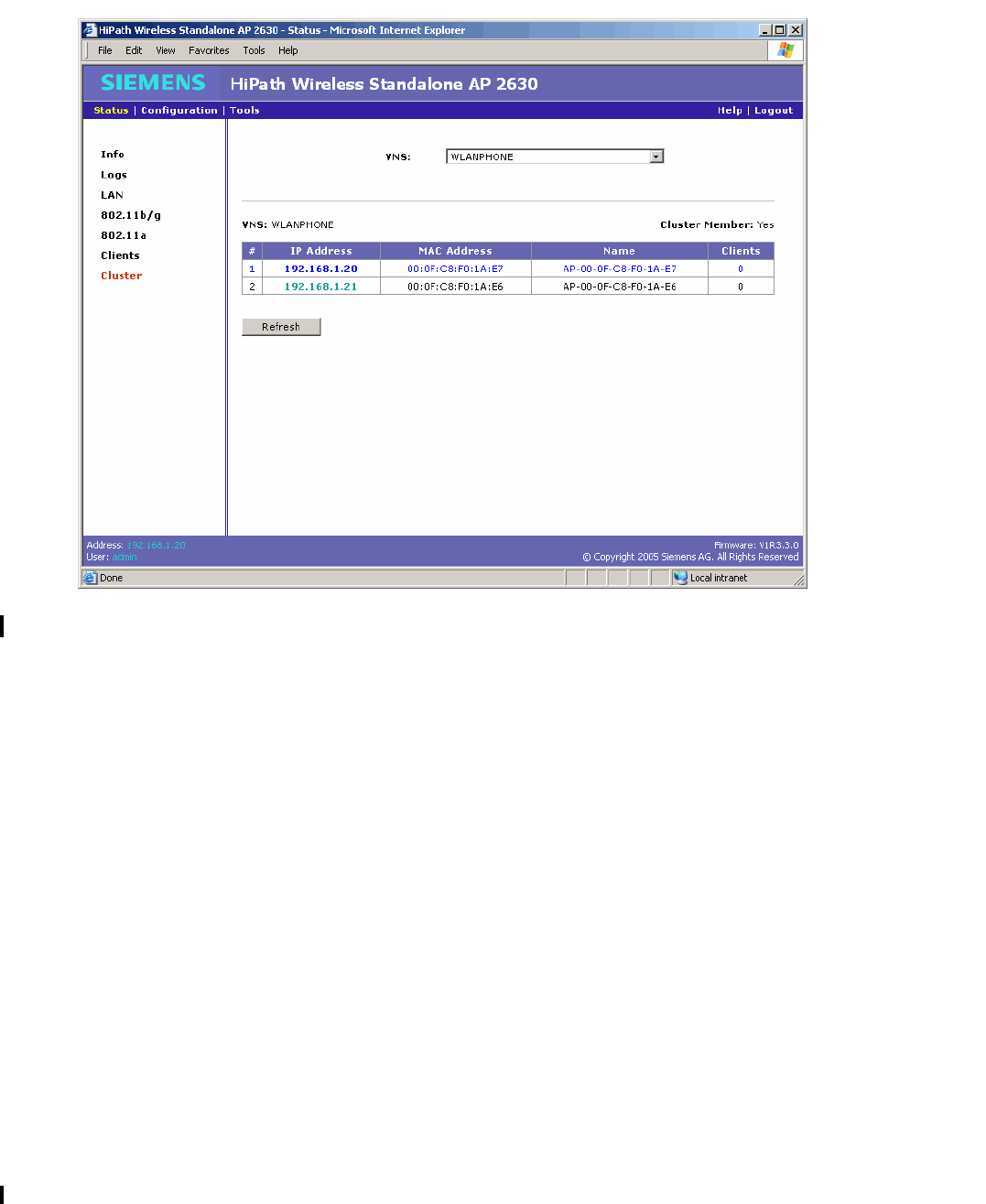
Troubleshooting the Standalone Access Point
A31003-W1110-U100-1-7619, DRAFT February 2007
102 HiPath Wireless Standalone Access Point V1.0, User Guide
HSAAP_Troubleshooting.fm
Viewing the cluster status information
3. From the VNS drop-down list, click the VNS/SSID you want to view.
4. To update the cluster data displayed to the most current data, click Refresh.

HSAAP_Glossary.fm
A31003-W1110-U100-1-7619, DRAFT February 2007
HiPath Wireless Standalone Access Point V1.0, User Guide 103
Glossary: Networking terms and abbreviations
8 Glossary: Networking terms and abbreviations
Term Definition
AAA Authentication, Authorization and Accounting.
A system in IP-based networking to control what computer resources users
have access to and to keep track of the activity of users over a network.
AC Access Class
AC_BE Access Class - Best Effort
Access Point
(AP)
The Standalone Access Point is a wireless LAN access point (IEEE 802.11)
provided with unique software that allows it to communicate only with an
access point. (A thin access point handles the radio frequency (RF)
communication but relies on a controller to handle WLAN elements such as
authentication.) The Standalone Access Point also provides local processing
such as encryption. The Standalone Access Point is a dual-band access
point, with 802.11a+b/g radios.
Ad-hoc mode An 802.11 networking framework in which devices or stations communicate
directly with each other, without the use of an access point (AP). (Compare
Infrastructure Mode)
AES Advanced Encryption Standard (AES)
An algorithm for encryption that works at multiple network layers
simultaneously. As a block cipher, AES encrypts data in fixed-size blocks of
128 bits. AES was created by the National Institute of Standards and
Technology (NIST). AES is a privacy transform for IPSec and Internet Key
Exchange (IKE). AES has a variable key length - the algorithm can specify a
128-bit key (the default), a 192-bit key, or a 256-bit key.
For the WPA2/802.11i implementation of AES, a 128 bit key length is used.
AES encryption includes 4 stages that make up one round. Each round is
then iterated 10, 12 or 14 times depending upon the bit-key size. For the
WPA2/802.11i implementation of AES, each round is iterated 10 times.
AES-CCMP AES uses the Counter-Mode/CBC-MAC Protocol (CCMP). CCM is a new
mode of operation for a block cipher that enables a single key to be used for
both encryption and authentication. The two underlying modes employed in
CCM include Counter mode (CTR) that achieves data encryption and Cipher
Block Chaining Message Authentication Code (CBC-MAC) to provide data
integrity.

Glossary: Networking terms and abbreviations
A31003-W1110-U100-1-7619, DRAFT February 2007
104 HiPath Wireless Standalone Access Point V1.0, User Guide
HSAAP_Glossary.fm
ARP Address Resolution Protocol.
A protocol used to obtain the physical addresses (such as MAC addresses) of
hardware units in a network environment. A host obtains such a physical
address by broadcasting an ARP request, which contains the IP address of the
target hardware unit. If the request finds a unit with that IP address, the unit
replies with its physical hardware address.
Association A connection between a wireless device and an access point.
BSS Basic Service Set.
A wireless topology consisting of one Access Point connected to a wired
network and a set of wireless devices. Also called an infrastructure network.
See also IBSS.
Collision Two Ethernet packets attempting to use the medium simultaneously. Ethernet
is a shared media, so there are rules for sending packets of data to avoid
conflicts and protect data integrity. When two nodes at different locations
attempt to send data at the same time, a collision will result. Segmenting the
network with bridges or switches is one way of reducing collisions in an
overcrowded network.
Datagram A datagram is "a self-contained, independent entity of data carrying sufficient
information to be routed from the source to the destination computer without
reliance on earlier exchanges between this source and destination computer
and the transporting network." (RFC1594). The term has been generally
replaced by the term packet. Datagrams or packets are the message units
that the Internet Protocol deals with and that the Internet transports.
DHCP Dynamic Host Configuration Protocol.
A protocol for assigning dynamic IP addresses to devices on a network. With
dynamic addressing, a device can have a different IP address every time it
connects to the network. In some systems, the device's IP address can even
change while it is still connected. DHCP also supports a mix of static and
dynamic IP addresses.
DHCP consists of two components: a protocol for delivering host-specific
configuration parameters from a DHCP server to a host and a mechanism for
allocation of network addresses to hosts. (IETF RFC1531.)
Option 78 specifies the location of one or more SLP Directory Agents. Option
79 specifies the list of scopes that a SLP Agent is configured to
use.(RFC2610 - DHCP Options for Service Location Protocol)
Term Definition

HSAAP_Glossary.fm
A31003-W1110-U100-1-7619, DRAFT February 2007
HiPath Wireless Standalone Access Point V1.0, User Guide 105
Glossary: Networking terms and abbreviations
DSSS Direct-Sequence Spread Spectrum.
A transmission technology used in Wireless Local Area Network (WLAN)
transmissions where a data signal at the sending station is combined with a
higher data rate bit sequence, or chipping code, that divides the user data
according to a spreading ratio. The chipping code is a redundant bit pattern
for each bit that is transmitted, which increases the signal's resistance to
interference. If one or more bits in the pattern are damaged during
transmission, the original data can be recovered due to the redundancy of the
transmission. (Compare FHSS)
DTIM Delivery Traffic Indication Message (in 802.11 standard)
EAP-TLS
EAP-TTLS
EAP-TLS Extensible Authentication Protocol - Transport Layer Security. A
general protocol for authentication that also supports multiple authentication
methods, such as token cards, Kerberos, one-time passwords, certificates,
public key authentication and smart cards. IEEE 802.1x specifies how EAP
should be encapsulated in LAN frames.
In wireless communications using EAP, a user requests connection to a
WLAN through an access point, which then requests the identity of the user
and transmits that identity to an authentication server such as RADIUS. The
server asks the access point for proof of identity, which the access point gets
from the user and then sends back to the server to complete the
authentication.
EAP-TLS provides for certificate-based and mutual authentication of the
client and the network. It relies on client-side and server-side certificates to
perform authentication and can be used to dynamically generate user-based
and session-based WEP keys.
EAP-TTLS (Tunneled Transport Layer Security) is an extension of EAP-TLS
to provide certificate-based, mutual authentication of the client and network
through an encrypted tunnel, as well as to generate dynamic, per-user, per-
session WEP keys. Unlike EAP-TLS, EAP-TTLS requires only server-side
certificates.
(See also PEAP)
ELA (OPSEC) Event Logging API (Application Program Interface) for OPSEC, a module in
Check Point used to enable third-party applications to log events into the
Check Point VPN-1/FireWall-1 management system.
ESS Extended Service Set (ESS). Several Basic Service Sets (BSSs) can be
joined together to form one logical WLAN segment, referred to as an
extended service set (ESS). The SSID is used to identify the ESS. (See BSS
and SSID.)
Term Definition

Glossary: Networking terms and abbreviations
A31003-W1110-U100-1-7619, DRAFT February 2007
106 HiPath Wireless Standalone Access Point V1.0, User Guide
HSAAP_Glossary.fm
FHSS Frequency-Hopping Spread Spectrum. A transmission technology used in
Wireless Local Area Network (WLAN) transmissions where the data signal is
modulated with a narrowband carrier signal that "hops" in a random but
predictable sequence from frequency to frequency as a function of time over
a wide band of frequencies. This technique reduces interference. If
synchronized properly, a single logical channel is maintained. (Compare
DSSS)
Fit, thin and fat
APs
A thin AP architecture uses two components: an access point that is
essentially a stripped-down radio and a centralized management controller
that handles the other WLAN system functions. Wired network switches are
also required.
A fit AP, a variation of the thin AP, handles the RF and encryption, while the
central management controller, aware of the wireless users' identities and
locations, handles secure roaming, quality of service, and user
authentication. The central management controller also handles AP
configuration and management.
A fat (or thick) AP architecture concentrates all the WLAN intelligence in the
access point. The AP handles the radio frequency (RF) communication, as
well as authenticating users, encrypting communications, secure roaming,
WLAN management, and in some cases, network routing.
FTP File Transfer Protocol
Gateway In the wireless world, an access point with additional software capabilities
such as providing NAT and DHCP. Gateways may also provide VPN support,
roaming, firewalls, various levels of security, etc.
GUI Graphical User Interface
Host (1) A computer (usually containing data) that is accessed by a user working
on a remote terminal, connected by modems and telephone lines.
(2) A computer that is connected to a TCP/IP network, including the Internet.
Each host has a unique IP address.
HTTP Hypertext Transfer Protocol is the set of rules for transferring files (text,
graphic images, sound, video, and other multimedia files) on the World Wide
Web. A Web browser makes use of HTTP. HTTP is an application protocol
that runs on top of the TCP/IP suite of protocols. (RFC2616: Hypertext
Transfer Protocol -- HTTP/1.1)
IAPP Inter-Access Point Protocol
IBSS Independent Basic Service Set. See BSS. An IBSS is the 802.11 term for an
adhoc network. See adhoc network.
Term Definition

HSAAP_Glossary.fm
A31003-W1110-U100-1-7619, DRAFT February 2007
HiPath Wireless Standalone Access Point V1.0, User Guide 107
Glossary: Networking terms and abbreviations
ICMP Internet Control Message Protocol, an extension to the Internet Protocol (IP)
defined by RFC792. ICMP supports packets containing error, control, and
informational messages. The PING command, for example, uses ICMP to
test an Internet connection.
ICV ICV (Integrity Check Value) is a 4-byte code appended in standard WEP to
the 802.11 message. Enhanced WPA inserts an 8-byte MIC just before the
ICV. (See WPA and MIC)
IE Internet Explorer.
IEEE Institute of Electrical and Electronics Engineers, a technical professional
association, involved in standards activities.
IETF Internet Engineering Task Force, the main standards organization for the
Internet.
Infrastructure
Mode
An 802.11 networking framework in which devices communicate with each
other by first going through an access point (AP). In infrastructure mode,
wireless devices can communicate with each other or can communicate with
a wired network. (See ad-hoc mode and BSS.)
Internet or IP
telephony
IP or Internet telephony are communications, such as voice, facsimile, voice-
messaging applications, that are transported over the Internet, rather than the
public switched telephone network (PSTN). IP telephony is the two-way
transmission of audio over a packet-switched IP network (TCP/IP network).
An Internet telephone call has two steps: (1) converting the analog voice
signal to digital format, (2) translating the signal into Internet protocol (IP)
packets for transmission over the Internet. At the receiving end, the steps are
reversed. Over the public Internet, voice quality varies considerably. Protocols
that support Quality of Service (QoS) are being implemented to improve this.
IP Internet Protocol is the method or protocol by which data is sent from one
computer to another on the Internet. Each computer (host) on the Internet has
at least one IP address that uniquely identifies it. Internet Protocol specifies
the format of packets, also called datagrams, and the addressing scheme.
Most networks combine IP with a higher-level protocol called Transmission
Control Protocol (TCP), which establishes a virtual connection between a
destination and a source.
Isochronous
data
Isochronous data is data (such as voice or video) that requires a constant
transmission rate, where data must be delivered within certain time
constraints. For example, multimedia streams require an isochronous
transport mechanism to ensure that data is delivered as fast as it is displayed
and to ensure that the audio is synchronized with the video. Compare:
asynchronous processes in which data streams can be broken by random
intervals, and synchronous processes, in which data streams can be
delivered only at specific intervals.
Term Definition

Glossary: Networking terms and abbreviations
A31003-W1110-U100-1-7619, DRAFT February 2007
108 HiPath Wireless Standalone Access Point V1.0, User Guide
HSAAP_Glossary.fm
ISP Internet Service Provider.
IV IV (Initialization Vector), part of the standard WEP encryption mechanism that
concatenates a shared secret key with a randomly generated 24-bit
initialization vector. WPA with TKIP uses 48-bit IVs, an enhancement that
significantly increases the difficulty in cracking the encryption. (See WPA and
TKIP)
LAN Local Area Network.
MAC Media Access Control layer. One of two sublayers that make up the Data Link
Layer of the OSI model. The MAC layer is responsible for moving data packets
to and from one Network Interface Card (NIC) to another across a shared
channel.
MAC address Media Access Control address. A hardware address that uniquely identifies
each node of a network.
MIC Message Integrity Check or Code (MIC), also called "Michael", is part of WPA
and TKIP. The MIC is an additional 8-byte code inserted before the standard
4-byte integrity check value (ICV) that is appended in by standard WEP to the
802.11 message. This greatly increases the difficulty in carrying out forgery
attacks.
Both integrity check mechanisms are calculated by the receiver and
compared against the values sent by the sender in the frame. If the values
match, there is assurance that the message has not been tampered with.
(See WPA, TKIP and ICV).
MTU Maximum Transmission Unit. The largest packet size, measured in bytes, that
a network interface is configured to accept. Any messages larger than the
MTU are divided into smaller packets before being sent.
MU Mobile Unit, a wireless device such as a PC laptop.
multicast,
broadcast,
unicast
Multicast: transmitting a single message to a select group of recipients.
Broadcast: sending a message to everyone connected to a network. Unicast:
communication over a network between a single sender and a single receiver.
Netmask In administering Internet sites, a netmask is a string of 0's and 1's that mask
or screen out the network part of an IP address, so that only the host
computer part of the address remains. A frequently-used netmask is
255.255.255.0, used for a Class C subnet (one with up to 255 host
computers). The ".0" in the "255.255.255.0" netmask allows the specific host
computer address to be visible.
NIC Network Interface Card.
An expansion board in a computer that connects the computer to a network.
Term Definition

HSAAP_Glossary.fm
A31003-W1110-U100-1-7619, DRAFT February 2007
HiPath Wireless Standalone Access Point V1.0, User Guide 109
Glossary: Networking terms and abbreviations
NMS Network Management System.
The system responsible for managing a network or a portion of a network.
The NMS talks to network management agents, which reside in the managed
nodes.
OFDM Orthogonal frequency division multiplexing, a method of digital modulation in
which a signal is split into several narrowband channels at different
frequencies. OFDM is similar to conventional frequency division multiplexing
(FDM). The difference lies in the way in which the signals are modulated and
demodulated. Priority is given to minimizing the interference, or crosstalk,
among the channels and symbols comprising the data stream. Less
importance is placed on perfecting individual channels.
OFDM is used in European digital audio broadcast services. It is also used in
wireless local area networks.
OS Operating system.
OSI Open System Interconnection. An ISO standard for worldwide
communications that defines a networking framework for implementing
protocols in seven layers. Control is passed from one layer to the next,
starting at the application layer in one station, down through the presentation,
session, transport, network, data link layer to the physical layer at the bottom,
over the channel to the next station and back up the hierarchy.
OSI Layer 2 At the Data Link layer (OSI Layer 2), data packets are encoded and decoded
into bits. The data link layer has two sublayers:
●the Logical Link Control (LLC) layer controls frame synchronization, flow
control and error checking
●The Media Access Control (MAC) layer controls how a computer on the
network gains access to the data and permission to transmit it.
OSI Layer 3 The Network layer (OSI Layer 3) provides switching and routing technologies,
creating logical paths, known as virtual circuits, for transmitting data from
node to node. Routing and forwarding are functions of this layer, as well as
addressing, internetworking, error handling, congestion control and packet
sequencing.
OUI Organizationally Unique Identifier (used in MAC addressing).
Term Definition

Glossary: Networking terms and abbreviations
A31003-W1110-U100-1-7619, DRAFT February 2007
110 HiPath Wireless Standalone Access Point V1.0, User Guide
HSAAP_Glossary.fm
Packet The unit of data that is routed between an origin and a destination on the
Internet or any other packet-switched network. When any file is sent from one
place to another on the Internet, the Transmission Control Protocol (TCP)
layer of TCP/IP divides the file into packets. Each packet is separately
numbered and includes the Internet address of the destination. The individual
packets for a given file may travel different routes through the Internet. When
they have all arrived, they are reassembled into the original file (by the TCP
layer at the receiving end).
PDU Protocol Data Unit. A data object exchanged by protocol machines (such as
management stations, SMUX peers, and SNMP agents) and consisting of both
protocol control information and user data. PDU is sometimes used as a
synonym for "packet''.
PKI Public Key Infrastructure
PoE Power over Ethernet. The Power over Ethernet standard (802.3af) defines
how power can be provided to network devices over existing Ethernet
connection, eliminating the need for additional external power supplies.
POST Power On Self Test, a diagnostic testing sequence performed by a computer
to determine if its hardware elements are present and powered on. If so, the
computer begins its boot sequence.
push-to-talk
(PTT)
The push-to-talk (PTT) is feature on wireless telephones that allows them to
operate like a walkie-talkie in a group, instead of standard telephone
operation. The PTT feature requires that the network be configured to allow
multicast traffic.
A PTT call is initiated by selecting a channel and pressing the "talk" key on
the wireless telephone. All wireless telephones on the same network that are
monitoring the channel will hear the transmission. On a PTT call you hold the
button to talk and release it to listen.
QoS Quality of Service. A term for a number of techniques that intelligently match
the needs of specific applications to the network resources available, using
such technologies as Frame Relay, Asynchronous Transfer Mode (ATM),
Ethernet and 802.1 networks, SONET, and IP-routed networks. QoS features
provide better network service by supporting dedicated bandwidth, improving
loss characteristics, avoiding and managing network congestion, shaping
network traffic, setting traffic priorities across the network.
Quality-of-Service (QoS): A set of service requirements to be met by the
network while transporting a flow. (RFC2386)
Term Definition

HSAAP_Glossary.fm
A31003-W1110-U100-1-7619, DRAFT February 2007
HiPath Wireless Standalone Access Point V1.0, User Guide 111
Glossary: Networking terms and abbreviations
RADIUS Remote Authentication Dial-In User Service. An authentication and
accounting system that checks User Name and Password and authorizes
access to a network. The RADIUS specification is maintained by a working
group of the IETF (RFC2865 RADIUS, RFC2866 RADIUS Accounting,
RFC2868 RADIUS Attributes for Tunnel Protocol Support).
RF Radio Frequency, a frequency in the electromagnetic spectrum associated with
radio wave propagation. When an RF current is supplied to an antenna, an
electromagnetic field is created that can propagate through space. These
frequencies in the electromagnetic spectrum range from Ultra-low frequency
(ULF) -- 0-3 Hz to Extremely high frequency (EHF) -- 30GHz - 300 GHz. The
middle ranges are: Low frequency (LF) -- 30 kHz - 300 kHz, Medium frequency
(MF) -- 300 kHz - 3 MHz, High frequency (HF) -- 3MHz - 30 MHz, Very high
frequency (VHF) -- 30 MHz - 300 MHz, Ultra-high frequency (UHF)-- 300MHz
- 3 GHz.
RFC Request for Comments, a series of notes about the Internet, submitted to the
Internet Engineering Task Force (IETF) and designated by an RFC number,
that may evolve into an Internet standard. The RFCs are catalogued and
maintained on the IETF RFC website: www.ietf.org/rfc.html.
Roaming In 802.11, roaming occurs when a wireless device (a station) moves from one
access point to another (or BSS to another) in the same Extended Service
Set (ESS) -identified by its SSID.
RP-SMA Reverse Polarity-Subminiature version A, a type of connector used with
wireless antennas
RSN Robust Security Network. A new standard within IEEE 802.11 to provide
security and privacy mechanisms. The RSN (and related TSN) both specify
IEEE 802.1x authentication with Extensible Authentication Protocol (EAP).
RSSI RSSI received signal strength indication (in 802.11 standard)
RTS / CTS RTS request to send, CTS clear to send (in 802.11 standard)
Segment In ethernet networks, a section of a network that is bounded by bridges,
routers or switches. Dividing a LAN segment into multiple smaller segments
is one of the most common ways of increasing available bandwidth on the
LAN.
SIAPP Siemens Inter-Access Point Protocol
Term Definition

Glossary: Networking terms and abbreviations
A31003-W1110-U100-1-7619, DRAFT February 2007
112 HiPath Wireless Standalone Access Point V1.0, User Guide
HSAAP_Glossary.fm
SSID Service Set Identifier
A 32-character unique identifier attached to the header of packets sent over
a Wireless LAN that acts as a password when a wireless device tries to
connect to the Basic Service Set (BSS). Several BSSs can be joined together
to form one logical WLAN segment, referred to as an extended service set
(ESS). The SSID is used to identify the ESS.
In 802.11 networks, each access point advertises its presence several times
per second by broadcasting beacon frames that carry the ESS name (SSID).
Stations discover APs by listening for beacons, or by sending probe frames
to search for an access point with a desired SSID. When the station locates
an appropriately-named access point, it sends an associate request frame
containing the desired SSID. The access point replies with an associate
response frame, also containing the SSID.
Some APs can be configured to send a zero-length broadcast SSID in
beacon frames instead of sending their actual SSID. The access point must
return its actual SSID in the probe response.
Subnet mask (See netmask)
Subnets Portions of networks that share the same common address format. A subnet
in a TCP/IP network uses the same first three sets of numbers (such as
198.63.45.xxx), leaving the fourth set to identify devices on the subnet. A
subnet can be used to increase the bandwidth on the network by breaking the
network up into segments.
SVP SpectraLink Voice Protocol, a protocol developed by SpectraLink to be
implemented on access points in order to facilitate voice prioritization over an
802.11 wireless LAN that will carry voice packets from SpectraLink wireless
telephones.
Switch In networks, a device that filters and forwards packets between LAN
segments. Switches operate at the data link layer (layer 2) and sometimes the
network layer (layer 3) of the OSI Reference Model and therefore support any
packet protocol. LANs that use switches to join segments are called switched
LANs or, in the case of Ethernet networks, switched Ethernet LANs.
TCP / IP Transmission Control Protocol.
TCP, together with IP (Internet Protocol), is the basic communication
language or protocol of the Internet. Transmission Control Protocol manages
the assembling of a message or file into smaller packets that are transmitted
over the Internet and received by a TCP layer that reassembles the packets
into the original message. Internet Protocol handles the address part of each
packet so that it gets to the right destination.
TCP/IP uses the client/server model of communication in which a computer
user (a client) requests and is provided a service (such as sending a Web
page) by another computer (a server) in the network.
Term Definition

HSAAP_Glossary.fm
A31003-W1110-U100-1-7619, DRAFT February 2007
HiPath Wireless Standalone Access Point V1.0, User Guide 113
Glossary: Networking terms and abbreviations
TFTP Trivial File Transfer Protocol.
An Internet software utility for transferring files that is simpler to use than the
File Transfer Protocol (FTP) but less capable. It is used where user
authentication and directory visibility are not required. TFTP uses the User
Datagram Protocol (UDP) rather than the Transmission Control Protocol
(TCP). TFTP is described formally in Request for Comments (RFC) 1350.
TKIP Temporal Key Integrity Protocol (TKIP) is an enhancement to the WEP
encryption technique that uses a set of algorithms that rotates the session
keys. TKIP's enhanced encryption includes a per-packet key mixing function,
a message integrity check (MIC), an extended initialization vector (IV) with
sequencing rules, and a re-keying mechanism. The encryption keys are
changed (rekeyed) automatically and authenticated between devices after
the rekey interval (either a specified period of time, or after a specified number
of packets has been transmitted).
ToS / DSCP ToS (Type of Service) / DSCP (Diffserve Codepoint). The ToS/DSCP field
contained in the IP header of a frame is used by applications to indicate the
priority and Quality of Service (QoS) for each frame. The level of service is
determined by a set of service parameters which provide a three way trade-
off between low-delay, high-reliability, and high-throughput. The use of
service parameters may increase the cost of service.
TSN Transition Security Network.
A subset of Robust Security Network (RSN), which provides an enhanced
security solution for legacy hardware. The Wi-Fi Alliance has adopted a
solution called Wireless Protected Access (WPA), based on TSN. RSN and
TSN both specify IEEE 802.1x authentication with Extensible Authentication
Protocol (EAP).
Tunnelling Tunnelling (or encapsulation) is a technology that enables one network to
send its data via another network's connections. Tunnelling works by
encapsulating packets of a network protocol within packets carried by the
second network. The receiving device then decapsulates the packets and
forwards them in their original format.
UDP User Datagram Protocol.
A connectionless protocol that, like TCP, runs on top of IP networks. Unlike
TCP/IP, UDP/IP provides very few error recovery services, offering instead a
direct way to send and receive packets over an IP network. It is used primarily
for broadcasting messages over a network.
Term Definition

Glossary: Networking terms and abbreviations
A31003-W1110-U100-1-7619, DRAFT February 2007
114 HiPath Wireless Standalone Access Point V1.0, User Guide
HSAAP_Glossary.fm
U-NII Unlicensed National Information Infrastructure.
Designated to provide short-range, high-speed wireless networking
communication at low cost, U-NII consists of three frequency bands of 100
MHz each in the 5 GHz band: 5.15-5.25GHz (for indoor use only), 5.25-5.35
GHz and 5.725-5.825GHz. The three frequency bands were set aside by the
FCC in 1997 initially to help schools connect to the Internet without the need
for hard wiring. U-NII devices do not require licensing.
URL Uniform Resource Locator.
The unique global address of resources or files on the World Wide Web. The
URL contains the name of the protocol to be used to access the file resource,
the IP address or the domain name of the computer where the resource is
located, and a pathname -- a hierarchical description that specifies the
location of a file in that computer.
VLAN Virtual Local Area Network.
A network of computers that behave as if they are connected to the same wire
when they may be physically located on different segments of a LAN. VLANs
are configured through software rather than hardware, which makes them
extremely flexible. When a computer is physically moved to another location,
it can stay on the same VLAN without any hardware reconfiguration.
The standard is defined in IEEE 802.1Q - Virtual LANs, which states that
"IEEE 802 Local Area Networks (LANs) of all types may be connected
together with Media Access Control (MAC) Bridges, as specified in ISO/IEC
15802-3. This standard defines the operation of Virtual LAN (VLAN) Bridges
that permit the definition, operation and administration of Virtual LAN
topologies within a Bridged LAN infrastructure."
VoIP Voice Over Internet Protocol.
An internet telephony technique. With VoIP, a voice transmission is cut into
multiple packets, takes the most efficient path along the Internet and is
reassembled when it reaches the destination.
VPN Virtual Private Network.
A private network that is constructed by using public wires to connect nodes.
These systems use encryption and other security mechanisms to ensure that
only authorized users can access the network and that the data cannot be
intercepted.
WEP Wired Equivalent Privacy.
A security protocol for wireless local area networks (WLANs) defined in the
802.11b standard. WEP aims to provide security by encrypting data over
radio waves so that it is protected as it is transmitted from one end point to
another.
Term Definition

HSAAP_Glossary.fm
A31003-W1110-U100-1-7619, DRAFT February 2007
HiPath Wireless Standalone Access Point V1.0, User Guide 115
Glossary: Networking terms and abbreviations
Wi-Fi Wireless fidelity.
A term referring to any type of 802.11 network, whether 802.11b, 802.11a,
dual-band, etc. Used in reference to the Wi-Fi Alliance, a nonprofit
international association formed in 1999 to certify interoperability of wireless
Local Area Network products based on IEEE 802.11 specification.
WINS Windows Internet Naming Service.
A system that determines the IP address associated with a particular network
computer, called name resolution. WINS supports network client and server
computers running Windows and can provide name resolution for other
computers with special arrangements. WINS supports dynamic addressing
(DHCP) by maintaining a distributed database that is automatically updated
with the names of computers currently available and the IP address assigned
to each one.
DNS is an alternative system for name resolution suitable for network
computers with fixed IP addresses.
WLAN Wireless Local Area Network.
WMM Wi-Fi Multimedia (WMM), a Wi-Fi Alliance certified standard that provides
multimedia enhancements for Wi-Fi networks that improve the user experience
for audio, video, and voice applications. This standard is compliant with the
IEEE 802.11e Quality of Service (QoS) extensions for 802.11 networks. WMM
provides prioritized media access by shortening the time between transmitting
packets for higher priority traffic. WMM is based on the Enhanced Distributed
Channel Access (EDCA) method.
WPA Wireless Protected Access, or Wi-Fi Protected Access.
Is a security solution adopted by the Wi-Fi Alliance that adds authentication
to WEP's basic encryption. For authentication, WPA specifies IEEE 802.1x
authentication with Extensible Authentication Protocol (EAP). For encryption,
WPA uses the Temporal Key Integrity Protocol (TKIP) mechanism, which
shares a starting key between devices, and then changes their encryption key
for every packet. Certificate Authentication (CA) can also be used. Also part
of the encryption mechanism are 802.1X for dynamic key distribution and
Message Integrity Check (MIC) a.k.a. "Michael".
WPA requires that all computers and devices have WPA software.
WPA-PSK Wi-Fi Protected Access with Pre-Shared Key, a special mode of WPA for
users without an enterprise authentication server. Instead, for authentication,
a Pre-Shared Key is used. The PSK is a shared secret (passphrase) that must
be entered in both the wireless access point or router and the WPA clients.
This preshared key should be a random sequence of characters at least 20
characters long or hexadecimal digits (numbers 0-9 and letters A-F) at least
24 hexadecimal digits long. After the initial shared secret, the Temporal Key
Integrity Protocol (TKIP) handles the encryption and automatic rekeying.
Term Definition

Glossary: Networking terms and abbreviations
A31003-W1110-U100-1-7619, DRAFT February 2007
116 HiPath Wireless Standalone Access Point V1.0, User Guide
HSAAP_Glossary.fm

HSAAP_Appendix_log_codes.fm
A31003-W1110-U100-1-7619, DRAFT February 2007
HiPath Wireless Standalone Access Point V1.0, User Guide 117
Appendix: Log codes and messages
A Appendix: Log codes and messages
Listed below are the log codes and messages provided by the Standalone Access Point.
Event
Code (1
byte)
GUI Log Message Comments
1 Reboot caused by "power loss" / "watchdog
timeout" / "software crash" / "Cli
Command." / …
Gives out access point reboot reason
2 Vulnerable time started after "2"
interruptions
Start of Vulnerable time, with previous
power interrupt during 2 consecutive
vulnerable time
3 Vulnerable time ended with no interruptions End of Vulnerable time
4 Configuration restored to factory defaults by
hardware reset
5 Cluster-VNS1 state changed to "Master" /
"Slave" / "Registering"
SIAPP major state change
6 Slave AP with IP "10.2.102.10" and MAC
"00-0F-C8-F0-1A-E6" accepted in the
cluster-VNS1
Master reports new slave accepted
7 Slave AP with IP "10.2.102.10" and MAC
"00-0F-C8-F0-1A-E6" removed from the
cluste-VNS1
Master reports slave removed
8 Client "00-0F-DD-F0-1A-E6" associated
with VNS1 BSSID "00-0F-C8-F0-1A-E8"
9 Client "00-0F-DD-F0-1A-E6" disassociated
from VNS1 BSSID "00-0F-C8-F0-1A-E8"
10 Client "00-0F-DD-F0-1A-E6"
(re)association denied by VNS1 BSSID "00-
0F-C8-F0-1A-E8"
11 Client "00-0F-DD-F0-1A-E6" reassociated
with VNS1 BSSID "00-0F-C8-F0-1A-E8" on
this AP from BSSID "00-0F-C8-F0-1A-D0"
12 Client "00-0F-DD-F0-1A-E6" moved from
VNS1 BSSID "00-0F-C8-F0-1A-E8" on this
AP to BSSID "00-0F-C8-F0-1A-D0"
13 User "admin" successfully logged in
14 User "admin" denied log in
Appendix

Appendix: Log codes and messages
A31003-W1110-U100-1-7619, DRAFT February 2007
118 HiPath Wireless Standalone Access Point V1.0, User Guide
HSAAP_Appendix_log_codes.fm
Table 14 Log codes and messages
15 Password for user "admin" successfully
changed
16 Configuration changed successfully
17 Configuration downloaded successfully Bulk configuration downloaded
18 Configuration restored to factory defaults by
software reset
19 Firmware upgraded successfully
20 BootROM upgraded successfully
21 Non-volatile log cleared
22 Debug info: “SIAPP 87 R0->M2”
23 Start checking for radar interference on
channel 5300
24 Finished checking for radar interference on
channel 5300
25 Radar detected. Switch to auto channel
select
26 Auto channel select found channel 5300
27 AP crash reaches a limit of 4 times
Event
Code (1
byte)
GUI Log Message Comments

HSAAP_Appendix_lists_of_standards.fm
A31003-W1110-U100-1-7619, DRAFT February 2007
HiPath Wireless Standalone Access Point V1.0, User Guide 119
Appendix: Supported standards
RFC list
B Appendix: Supported standards
B.1 RFC list
Listed below are the Internet Engineering Task Force (IETF) Request for Comments (RFC)
standards supported by the Standalone Access Point.
The Request for Comments, a series of notes about the Internet, is submitted to the Internet
Engineering Task Force (IETF) and designated by an RFC number, that may evolve into an
Internet standard. The RFCs are catalogued and maintained on the IETF RFC
website:www.ietf.org/rfc.html.
Table 15 List of Standalone Access Point supported RFCs
RFC
Number
Title
RFC 791 IPv4
RFC 1812 Minimum Router Requirements
RFC 793 Transport Control Protocol (TCP)
RFC 768 User Datagram Protocol (UDP)
RFC 792 Internet Control Message Protocol (ICMP)
RFC 826 Address Resolution Protocol (ARP)
RFC 2131 Dynamic Host Configuration Protocol (DHCP)
RFC 1155 Structure and identification of management information for TCP/IP-based
Internets.
RFC 959 File Transfer Protocol. (FTP)
RFC 2616 The HyperText Transfer Protocol (HTTP)
Appendix

Appendix: Supported standards
A31003-W1110-U100-1-7619, DRAFT February 2007
120 HiPath Wireless Standalone Access Point V1.0, User Guide
HSAAP_Appendix_lists_of_standards.fm
802.11 standards list
B.2 802.11 standards list
Also supported are the IEEE 802.11 standards listed below:
Table 16 List of 802.11 standards supported
Standard Name Comment
802.11 Wireless LAN MAC and PHY
Specifications
802.11a Wireless LAN High Speed Physical Layer in 5 GHz band
802.11b Wireless LAN High Speed Physical Layer in 2.4 GHz band
802.11d 802.11 Extensions to Operate in
Additional Regulatory Domains
802.11g Wireless LAN Further High Data Rate Extensions in 2.4 GHz
band
802.11i WLAN security and provide
better network access control
802.11e MAC Enhancements for Quality
of Service (future)
802.3af DTE Power via MDI (Power over
Ethernet)
802.3 CSMA/CD (Ethernet)
802.3i 10Base-T
802.3u 100Base-T
802.3x Full Duplex
802.1d MAC bridges

HiPath_Wireless_StandaloneIX.fm
A31003-W1110-U100-1-7619, DRAFT February 2007
HiPath Wireless Standalone Access Point V1.0, User Guide 1
Nur für den internen Gebrauch Index
Index Z
Numerics
802.11e 48
A
access point
advantages 46
components 46
configuring 61
connecting 50
features 45
installing 49
logging on 53
powering 50
user interface 53
administrator 53
B
BootROM 90
C
cluster 48
configuration
managing 87
saving 87
upgrading BootROM 90
D
Diffserve Codepoint (DSCP) 48
E
encryption approaches 47
F
factory default settings
restoring 52
firmware
downloading 56
G
general user 53
L
LAN settings
configuring 61
LED status 51
M
menu
administrator 53
general user 53
N
network security 47
P
passwords
changing 55
default 53
Power by AC adaptor 50
Power over Ethernet (PoE) 50
adding a PoE injector 50
Q
QoS
VNS 48
Quality of Service (QoS) 48
R
random delays 51, 52
S
Secure Inter Access Point Protocol (SIAPP)
48
T
Type of Service (IP ToS) 48
U
user interface 53
user states 53
user types 53

Index Nur für den internen Gebrauch
A31003-W1110-U100-1-7619, DRAFT February 2007
2HiPath Wireless Standalone Access Point V1.0, User Guide
HiPath_Wireless_StandaloneIX.fm
V
VNS 75
configuring 75
configuring QoS 82
configuring radio frequency 77
configuring security 78
vulnerable time interval 51, 52
W
Wi-Fi Multimedia (WMM) 48
wireless settings
802.11a advanced configuring 71
802.11b/g advanced configuring 67
configuring 63
filter configuring 65
QoS configuring 74

© Siemens Enterprise Communications GmbH & Co. KG •
Hofmannstraße 51 • D-81359 München, Germany
Reference No.: A31003-W1110-U100-1-7619
Subject to availability. Right of modification reserved.
www.siemens.com/hipath