Chantry Networks APXXX1 HiPATH WIRELESS ACCESS POINT (AP) User Manual
Chantry Networks Inc. (a Siemens Company) HiPATH WIRELESS ACCESS POINT (AP)
Contents
User Manual

P/N 9034530-09
Enterasys® Wireless
Convergence Software
User Guide
Version 8.11
DRAFT
DRAFT
i
Notice
Enterasys Networks reserves the right to make changes in specifications and other information contained in this document and
its web site without prior notice. The reader should in all cases consult Enterasys Networks to determine whether any such
changes have been made.
The hardware, firmware, or software described in this document is subject to change without notice.
IN NO EVENT SHALL ENTERASYS NETWORKS BE LIABLE FOR ANY INCIDENTAL, INDIRECT, SPECIAL, OR
CONSEQUENTIAL DAMAGES WHATSOEVER (INCLUDING BUT NOT LIMITED TO LOST PROFITS) ARISING OUT OF
OR RELATED TO THIS DOCUMENT, WEB SITE, OR THE INFORMATION CONTAINED IN THEM, EVEN IF
ENTERASYS NETWORKS HAS BEEN ADVISED OF, KNEW OF, OR SHOULD HAVE KNOWN OF, THE POSSIBILITY OF
SUCH DAMAGES.
Enterasys Networks, Inc.
50 Minuteman Road
Andover, MA 01810
© 2012 Enterasys Networks, Inc. All rights reserved.
Part Number: 9034530-09 March 2012
ENTERASYS, ENTERASYS NETWORKS, ENTERASYS SECURE NETWORKS, DRAGON, ENTERASYS DRAGON,
NETSIGHT, ENTERASYS NETSIGHT, and any logos associated therewith, are trademarks or registered trademarks of
Enterasys Networks, Inc., in the United States and/or other countries. For a complete list of Enterasys trademarks, see
http://www.enterasys.com/company/trademarks.aspx.
All other product names mentioned in this manual may be trademarks or registered trademarks of their respective companies.
Documentation URL: https://extranet.enterasys.com/downloads/
DRAFT
ii
Enterasys Networks, Inc. Software License Agreement
This document is an agreement (“Agreement”) between You, the end user, and Enterasys Networks, Inc. on behalf of itself and
its Affiliates (“Enterasys”) that sets forth your rights and obligations with respect to the software contained in CD-ROM or
other media. “Affiliates” means any person, partnership, corporation, limited liability company, or other form of enterprise that
directly or indirectly through one or more intermediaries, controls, or is controlled by, or is under common control with the
party specified. BY INSTALLING THE ENCLOSED PRODUCT, YOU ARE AGREEING TO BECOME BOUND BY THE TERMS
OF THIS AGREEMENT, WHICH INCLUDES THE LICENSE AND THE LIMITATION OF WARRANTY AND DISCLAIMER
OF LIABILITY. IF YOU DO NOT AGREE TO THE TERMS OF THIS AGREEMENT, RETURN THE UNOPENED PRODUCT TO
ENTERASYS OR YOUR DEALER, IF ANY, WITHIN TEN (10) DAYS FOLLOWING THE DATE OF RECEIPT FOR A FULL
REFUND.
IF YOU HAVE ANY QUESTIONS ABOUT THIS AGREEMENT, CONTACT ENTERASYS NETWORKS, INC. (978) 684-1000.
Attn: Legal Department.
Enterasys will grant You a non-transferable, non-exclusive license to use the machine-readable form of software (the “Licensed
Software”) and the accompanying documentation (the Licensed Software, the media embodying the Licensed Software, and the
documentation are collectively referred to in this Agreement as the “Licensed Materials”) on one single computer if You agree
to the following terms and conditions:
1. TERM. This Agreement is effective from the date on which You open the package containing the Licensed Materials. You
may terminate the Agreement at any time by destroying the Licensed Materials, together with all copies, modifications and
merged portions in any form. The Agreement and your license to use the Licensed Materials will also terminate if You fail to
comply with any term or condition herein.
2. GRANT OF SOFTWARE LICENSE. The license granted to You by Enterasys when You open this sealed package
authorizes You to use the Licensed Software on any one, single computer only, or any replacement for that computer, for internal
use only. A separate license, under a separate Software License Agreement, is required for any other computer on which You or
another individual or employee intend to use the Licensed Software. YOU MAY NOT USE, COPY, OR MODIFY THE LICENSED
MATERIALS, IN WHOLE OR IN PART, EXCEPT AS EXPRESSLY PROVIDED IN THIS AGREEMENT.
3. RESTRICTION AGAINST COPYING OR MODIFYING LICENSED MATERIALS. Except as expressly permitted in this
Agreement, You may not copy or otherwise reproduce the Licensed Materials. In no event does the limited copying or
reproduction permitted under this Agreement include the right to decompile, disassemble, electronically transfer, or reverse
engineer the Licensed Software, or to translate the Licensed Software into another computer language.
The media embodying the Licensed Software may be copied by You, in whole or in part, into printed or machine readable
form, in sufficient numbers only for backup or archival purposes, or to replace a worn or defective copy. However, You agree
not to have more than two (2) copies of the Licensed Software in whole or in part, including the original media, in your
possession for said purposes without Enterasys’ prior written consent, and in no event shall You operate more than one copy of
the Licensed Software. You may not copy or reproduce the documentation. You agree to maintain appropriate records of the
location of the original media and all copies of the Licensed Software, in whole or in part, made by You. You may modify the
machine-readable form of the Licensed Software for (1) your own internal use or (2) to merge the Licensed Software into other
program material to form a modular work for your own use, provided that such work remains modular, but on termination of
this Agreement, You are required to completely remove the Licensed Software from any such modular work. Any portion of the
Licensed Software included in any such modular work shall be used only on a single computer for internal purposes and shall
remain subject to all the terms and conditions of this Agreement.
You agree to include any copyright or other proprietary notice set forth on the label of the media embodying the Licensed
Software on any copy of the Licensed Software in any form, in whole or in part, or on any modification of the Licensed Software
or any such modular work containing the Licensed Software or any part thereof.
4. TITLE AND PROPRIETARY RIGHTS.
(a) The Licensed Materials are copyrighted works and are the sole and exclusive property of Enterasys, any company or a
division thereof which Enterasys controls or is controlled by, or which may result from the merger or consolidation
with Enterasys (its “Affiliates”), and/or their suppliers. This Agreement conveys a limited right to operate the Licensed
Materials and shall not be construed to convey title to the Licensed Materials to You. There are no implied rights. You
shall not sell, lease, transfer, sublicense, dispose of, or otherwise make available the Licensed Materials or any portion
thereof, to any other party.
(b) You further acknowledge that in the event of a breach of this Agreement, Enterasys shall suffer severe and irreparable
damages for which monetary compensation alone will be inadequate. You therefore agree that in the event of a breach
of this Agreement, Enterasys shall be entitled to monetary damages and its reasonable attorney’s fees and costs in
enforcing this Agreement, as well as injunctive relief to restrain such breach, in addition to any other remedies available
to Enterasys.
DRAFT
iii
5. PROTECTION AND SECURITY. In the performance of this Agreement or in contemplation thereof, You and your
employees and agents may have access to private or confidential information owned or controlled by Enterasys relating to the
Licensed Materials supplied hereunder including, but not limited to, product specifications and schematics, and such
information may contain proprietary details and disclosures. All information and data so acquired by You or your employees or
agents under this Agreement or in contemplation hereof shall be and shall remain Enterasys’ exclusive property, and You shall
use your best efforts (which in any event shall not be less than the efforts You take to ensure the confidentiality of your own
proprietary and other confidential information) to keep, and have your employees and agents keep, any and all such information
and data confidential, and shall not copy, publish, or disclose it to others, without Enterasys’ prior written approval, and shall
return such information and data to Enterasys at its request. Nothing herein shall limit your use or dissemination of information
not actually derived from Enterasys or of information which has been or subsequently is made public by Enterasys, or a third
party having authority to do so.
You agree not to deliver or otherwise make available the Licensed Materials or any part thereof, including without
limitation the object or source code (if provided) of the Licensed Software, to any party other than Enterasys or its employees,
except for purposes specifically related to your use of the Licensed Software on a single computer as expressly provided in this
Agreement, without the prior written consent of Enterasys. You agree to use your best efforts and take all reasonable steps to
safeguard the Licensed Materials to ensure that no unauthorized personnel shall have access thereto and that no unauthorized
copy, publication, disclosure, or distribution, in whole or in part, in any form shall be made, and You agree to notify Enterasys
of any unauthorized use thereof. You acknowledge that the Licensed Materials contain valuable confidential information and
trade secrets, and that unauthorized use, copying and/or disclosure thereof are harmful to Enterasys or its Affiliates and/or
its/their software suppliers.
6. MAINTENANCE AND UPDATES. Updates and certain maintenance and support services, if any, shall be provided to
You pursuant to the terms of an Enterasys Service and Maintenance Agreement, if Enterasys and You enter into such an
agreement. Except as specifically set forth in such agreement, Enterasys shall not be under any obligation to provide Software
Updates, modifications, or enhancements, or Software maintenance and support services to You.
7. DEFAULT AND TERMINATION. In the event that You shall fail to keep, observe, or perform any obligation under this
Agreement, including a failure to pay any sums due to Enterasys, or in the event that You become insolvent or seek protection,
voluntarily or involuntarily, under any bankruptcy law, Enterasys may, in addition to any other remedies it may have under
law, terminate the License and any other agreements between Enterasys and You.
(a) Immediately after any termination of the Agreement or if You have for any reason discontinued use of Software, You
shall return to Enterasys the original and any copies of the Licensed Materials and remove the Licensed Software from
any modular works made pursuant to Section 3, and certify in writing that through your best efforts and to the best of
your knowledge the original and all copies of the terminated or discontinued Licensed Materials have been returned
to Enterasys.
(b) Sections 4, 5, 7, 8, 9, 10, 11, and 12 shall survive termination of this Agreement for any reason.
8. EXPORT REQUIREMENTS. You understand that Enterasys and its Affiliates are subject to regulation by agencies of the
U.S. Government, including the U.S. Department of Commerce, which prohibit export or diversion of certain technical products
to certain countries, unless a license to export the product is obtained from the U.S. Government or an exception from obtaining
such license may be relied upon by the exporting party.
If the Licensed Materials are exported from the United States pursuant to the License Exception CIV under the U.S. Export
Administration Regulations, You agree that You are a civil end user of the Licensed Materials and agree that You will use the
Licensed Materials for civil end uses only and not for military purposes.
If the Licensed Materials are exported from the United States pursuant to the License Exception TSR under the U.S. Export
Administration Regulations, in addition to the restriction on transfer set forth in Section 4 of this Agreement, You agree not to
(i) reexport or release the Licensed Software, the source code for the Licensed Software or technology to a national of a country
in Country Groups D:1 or E:2 (Albania, Armenia, Azerbaijan, Belarus, Cambodia, Cuba, Georgia, Iraq, Kazakhstan, Kyrgyzstan,
Laos, Libya, Macau, Moldova, Mongolia, North Korea, the People’s Republic of China, Russia, Tajikistan, Turkmenistan,
Ukraine, Uzbekistan, Vietnam, or such other countries as may be designated by the United States Government), (ii) export to
Country Groups D:1 or E:2 (as defined herein) the direct product of the Licensed Software or the technology, if such foreign
produced direct product is subject to national security controls as identified on the U.S. Commerce Control List, or (iii) if the
direct product of the technology is a complete plant o r any major component of a plant, export to Country Groups D:1 or E:2
the direct product of the plant or a major component thereof, if such foreign produced direct product is subject to national
security controls as identified on the U.S. Commerce Control List or is subject to State Department controls under the U.S.
Munitions List.
DRAFT
iv
9. UNITED STATES GOVERNMENT RESTRICTED RIGHTS. The Licensed Materials (i) were developed solely at private
expense; (ii) contains “restricted computer software” submitted with restricted rights in accordance with section 52.227-19 (a)
through (d) of the Commercial Computer Software-Restricted Rights Clause and its successors, and (iii) in all respects is
proprietary data belonging to Enterasys and/or its suppliers. For Department of Defense units, the Licensed Materials are
considered commercial computer software in accordance with DFARS section 227.7202-3 and its successors, and use,
duplication, or disclosure by the U.S. Government is subject to restrictions set forth herein.
10. LIMITED WARRANTY AND LIMITATION OF LIABILITY. The only warranty Enterasys makes to You in connection
with this license of the Licensed Materials is that if the media on which the Licensed Software is recorded is defective, it will be
replaced without charge, if Enterasys in good faith determines that the media and proof of payment of the license fee are
returned to Enterasys or the dealer from whom it was obtained within ninety (90) days of the date of payment of the license fee.
NEITHER ENTERASYS NOR ITS AFFILIATES MAKE ANY OTHER WARRANTY OR REPRESENTATION, EXPRESS OR
IMPLIED, WITH RESPECT TO THE LICENSED MATERIALS, WHICH ARE LICENSED "AS IS". THE LIMITED WARRANTY
AND REMEDY PROVIDED ABOVE ARE EXCLUSIVE AND IN LIEU OF ALL OTHER WARRANTIES, INCLUDING
IMPLIED WARRANTIES OF MERCHANTABILITY OR FITNESS FOR A PARTICULAR PURPOSE, WHICH ARE EXPRESSLY
DISCLAIMED, AND STATEMENTS OR REPRESENTATIONS MADE BY ANY OTHER PERSON OR FIRM ARE VOID. ONLY
TO THE EXTENT SUCH EXCLUSION OF ANY IMPLIED WARRANTY IS NOT PERMITTED BY LAW, THE DURATION OF
SUCH IMPLIED WARRANTY IS LIMITED TO THE DURATION OF THE LIMITED WARRANTY SET FORTH ABOVE. YOU
ASSUME ALL RISK AS TO THE QUALITY, FUNCTION AND PERFORMANCE OF THE LICENSED MATERIALS. IN NO
EVENT WILL ENTERASYS OR ANY OTHER PARTY WHO HAS BEEN INVOLVED IN THE CREATION, PRODUCTION OR
DELIVERY OF THE LICENSED MATERIALS BE LIABLE FOR SPECIAL, DIRECT, INDIRECT, RELIANCE, INCIDENTAL OR
CONSEQUENTIAL DAMAGES, INCLUDING LOSS OF DATA OR PROFITS OR FOR INABILITY TO USE THE LICENSED
MATERIALS, TO ANY PARTY EVEN IF ENTERASYS OR SUCH OTHER PARTY HAS BEEN ADVISED OF THE POSSIBILITY
OF SUCH DAMAGES. IN NO EVENT SHALL ENTERASYS OR SUCH OTHER PARTY'S LIABILITY FOR ANY DAMAGES
OR LOSS TO YOU OR ANY OTHER PARTY EXCEED THE LICENSE FEE YOU PAID FOR THE LICENSED MATERIALS.
Some states do not allow limitations on how long an implied warranty lasts and some states do not allow the exclusion or
limitation of incidental or consequential damages, so the above limitation and exclusion may not apply to You. This limited
warranty gives You specific legal rights, and You may also have other rights which vary from state to state.
11. JURISDICTION. The rights and obligations of the parties to this Agreement shall be governed and construed in
accordance with the laws and in the State and Federal courts of the Commonwealth of Massachusetts, without regard to its rules
with respect to choice of law. You waive any objections to the personal jurisdiction and venue of such courts. None of the 1980
United Nations Convention on the Limitation Period in the International Sale of Goods, and the Uniform Computer Information
Transactions Act shall apply to this Agreement.
12. GENERAL.
(a) This Agreement is the entire agreement between Enterasys and You regarding the Licensed Materials, and all prior
agreements, representations, statements, and undertakings, oral or written, are hereby expressly superseded and
canceled.
(b) This Agreement may not be changed or amended except in writing signed by both parties hereto.
(c) You represent that You have full right and/or authorization to enter into this Agreement.
(d) This Agreement shall not be assignable by You without the express written consent of Enterasys, The rights of
Enterasys and Your obligations under this Agreement shall inure to the benefit of Enterasys’ assignees, licensors, and
licensees.
(e) Section headings are for convenience only and shall not be considered in the interpretation of this Agreement.
(f) The provisions of the Agreement are severable and if any one or more of the provisions hereof are judicially determined
to be illegal or otherwise unenforceable, in whole or in part, the remaining provisions of this Agreement shall
nevertheless be binding on and enforceable by and between the parties hereto.
(g) Enterasys’ waiver of any right shall not constitute waiver of that right in future. This Agreement constitutes the entire
understanding between the parties with respect to the subject matter hereof, and all prior agreements, representations,
statements and undertakings, oral or written, are hereby expressly superseded and canceled. No purchase order shall
supersede this Agreement.
(h) Should You have any questions regarding this Agreement, You may contact Enterasys at the address set forth below.
Any notice or other communication to be sent to Enterasys must be mailed by certified mail to the following address:
ENTERASYS NETWORKS, INC., 50 Minuteman Road, Andover, MA 01810 Attn: Manager - Legal Department.
DRAFT

v
Contents
About This Guide
Intended Audience ............................................................................................................................................xv
How to Use This Guide .....................................................................................................................................xv
Formatting Conventions ..................................................................................................................................xvi
Additional Documentation ............................................................................................................................... xvii
Getting Help .................................................................................................................................................... xvii
Safety Information ......................................................................................................................................... xviii
Sicherheitshinweise .........................................................................................................................................xix
Consignes De Sécurité .....................................................................................................................................xx
Chapter 1: Overview of the Enterasys Wireless Convergence Software Solution
Introduction ..................................................................................................................................................... 1-1
The Enterasys Wireless System .............................................................................................................. 1-1
Conventional Wireless LANs .......................................................................................................................... 1-2
Elements of the Enterasys Wireless Convergence Software Solution ........................................................... 1-3
Enterasys NetSight Suite Integration ....................................................................................................... 1-6
Enterasys Wireless Convergence Software and Your Network ..................................................................... 1-7
Network Traffic Flow ................................................................................................................................ 1-8
Network Security ...................................................................................................................................... 1-9
Virtual Network Services ........................................................................................................................ 1-11
VNS Components .................................................................................................................................. 1-14
Routing ................................................................................................................................................... 1-16
Mobility and Roaming ............................................................................................................................. 1-16
Network Availability ................................................................................................................................ 1-17
Quality of Service (QoS) ........................................................................................................................ 1-17
Enterasys Wireless Controller Product Family ............................................................................................. 1-17
Chapter 2: Configuring the Enterasys Wireless Controller
System Configuration Overview ..................................................................................................................... 2-1
Logging on to the Enterasys Wireless Controller ........................................................................................... 2-4
Wireless Assistant Home Screen ................................................................................................................... 2-4
Working with the Basic Installation Wizard ..................................................................................................... 2-7
Configuring the Enterasys Wireless Controller for the First Time ................................................................. 2-12
Changing the Administrator Password ................................................................................................... 2-13
Applying Product License Keys .............................................................................................................. 2-13
Setting Up the Data Ports ...................................................................................................................... 2-16
Setting Up Internal VLAN ID and Multicast Support ............................................................................... 2-22
Setting Up Static Routes ........................................................................................................................ 2-23
Setting Up OSPF Routing ...................................................................................................................... 2-24
Configuring Filtering at the Interface Level ............................................................................................ 2-27
Protecting the Controller’s Interfaces and Internal Captive Portal Page ................................................ 2-30
Configuring the Login Authentication Mode ........................................................................................... 2-35
Configuring SNMP ................................................................................................................................. 2-45
Configuring Network Time ...................................................................................................................... 2-48
Configuring Secure Connections ........................................................................................................... 2-51
Configuring DNS Servers for Resolving Host Names of NTP and RADIUS Servers ............................. 2-52
Using an AeroScout/Ekahau Location-Based Solution ................................................................................ 2-53
Additional Ongoing Operations of the System .............................................................................................. 2-56
DRAFT
vi
Chapter 3: Configuring the Wireless AP
Wireless AP Overview .................................................................................................................................... 3-1
Enterasys Standard Wireless AP ............................................................................................................. 3-2
Enterasys Wireless Outdoor APs ............................................................................................................. 3-4
Enterasys Wireless 802.11n AP ............................................................................................................... 3-5
Wireless AP International Licensing ......................................................................................................... 3-9
Wireless AP Default IP Address and First-time Configuration ................................................................. 3-9
Assigning a Static IP Address to the Wireless AP ................................................................................. 3-10
Discovery and Registration Overview ........................................................................................................... 3-10
Wireless AP Discovery ........................................................................................................................... 3-10
Registration After Discovery ................................................................................................................... 3-11
Understanding the Wireless AP LED Status .......................................................................................... 3-12
Configuring the Wireless APs for the First Time .................................................................................... 3-25
Defining Properties for the Discovery Process ....................................................................................... 3-26
Connecting and Initiating the Wireless AP Discovery and Registration Process ................................... 3-28
Adding and Registering a Wireless AP Manually ......................................................................................... 3-28
Configuring Wireless AP Settings ................................................................................................................. 3-29
Modifying a Wireless AP’s Status .......................................................................................................... 3-30
Configuring a Wireless AP’s Properties ................................................................................................. 3-31
AP Properties Tab Configuration ........................................................................................................... 3-31
Assigning Wireless AP Radios to a VNS ............................................................................................... 3-35
Configuring Wireless AP Radio Properties ............................................................................................ 3-36
Setting Up the Wireless AP Using Static Configuration ......................................................................... 3-61
Configuring Telnet/SSH Access ............................................................................................................. 3-64
Configuring VLAN Tags for Wireless APs .................................................................................................... 3-65
Setting Up 802.1x Authentication for a Wireless AP .............................................................................. 3-66
Setting Up 802.1x Authentication for Wireless APs Using Multi-edit ..................................................... 3-73
Configuring the Default Wireless AP Settings ........................................................................................ 3-76
Modifying a Wireless AP’s Properties Based on a Default AP Configuration ............................................. 3-107
Modifying the Wireless AP’s Default Setting Using the Copy to Defaults Feature ..................................... 3-108
Configuring Multiple Wireless APs Simultaneously .................................................................................... 3-108
Configuring Co-located APs in Load Balance Groups ................................................................................ 3-111
How Availability Affects Load Balancing .............................................................................................. 3-116
Load Balance Group Statistics ............................................................................................................. 3-116
Configuring an AP Cluster .......................................................................................................................... 3-117
Converting the Wireless AP to Standalone Mode ...................................................................................... 3-118
Configuring an AP as a Sensor .................................................................................................................. 3-119
Performing Wireless AP Software Maintenance ......................................................................................... 3-121
Chapter 4: Configuring Topologies
Topology Overview ......................................................................................................................................... 4-1
Configuring a Basic Topology ......................................................................................................................... 4-2
Enabling Management Traffic ......................................................................................................................... 4-3
Layer 3 Configuration ..................................................................................................................................... 4-4
IP Address Configuration ......................................................................................................................... 4-4
DHCP Configuration ................................................................................................................................. 4-6
Defining a Next Hop Route and OSPF Advertisement ............................................................................. 4-8
Exception Filtering .......................................................................................................................................... 4-9
Multicast Filtering .......................................................................................................................................... 4-13
Chapter 5: Configuring Policies
Policy Overview .............................................................................................................................................. 5-1
Configuring VLAN and Class of Service for a Policy ...................................................................................... 5-1
Filtering Rules ................................................................................................................................................. 5-3
Filtering Rules for a Non-Authenticated Filter .......................................................................................... 5-3
DRAFT
vii
Non-authenticated Filter Examples .......................................................................................................... 5-4
Authenticated Filter Examples ................................................................................................................. 5-5
ICMP Type Enforcement .......................................................................................................................... 5-5
Filtering Rules for a Default Filter ............................................................................................................. 5-5
Defining Filter Rules for Wireless APs ..................................................................................................... 5-6
Configuring Filter Rules ............................................................................................................................ 5-7
Chapter 6: Configuring WLAN Services
WLAN Services Overview .............................................................................................................................. 6-1
Third-party AP WLAN Service Type ............................................................................................................... 6-2
Configuring a Basic WLAN Service ................................................................................................................ 6-2
Configuring Privacy ........................................................................................................................................ 6-8
About Wi-Fi Protected Access (WPA V1 and WPA V2) ........................................................................... 6-9
Wireless 802.11n APs and WPA Authentication ....................................................................................6-10
WPA Key Management Options ............................................................................................................ 6-11
Configuring WLAN Service Privacy ........................................................................................................ 6-11
Configuring Accounting and Authentication .................................................................................................. 6-14
Vendor Specific Attributes ...................................................................................................................... 6-14
Defining Accounting Methods for a WLAN Service ................................................................................ 6-15
Configuring Authentication for a WLAN Service .................................................................................... 6-17
MAC-Based Authentication for a WLAN Service ................................................................................... 6-18
Assigning RADIUS Servers for Authentication ....................................................................................... 6-18
Defining the RADIUS Server Priority for RADIUS Redundancy ............................................................. 6-20
Configuring Assigned RADIUS Servers ................................................................................................. 6-20
Defining a WLAN Service with No Authentication .................................................................................. 6-23
Configuring Captive Portal for Internal or External Authentication ......................................................... 6-24
Configuring the QoS Policy .......................................................................................................................... 6-34
Defining Priority Level and Service Class .............................................................................................. 6-36
Defining the Service Class ..................................................................................................................... 6-36
Configuring the Priority Override ............................................................................................................ 6-37
QoS Modes ............................................................................................................................................ 6-37
Chapter 7: Configuring a VNS
High Level VNS Configuration Flow ............................................................................................................... 7-1
Controller Defaults ................................................................................................................................... 7-2
VNS Global Settings ....................................................................................................................................... 7-3
Defining RADIUS Servers and MAC Address Format ............................................................................. 7-4
Configuring Dynamic Authorization Server Support ................................................................................. 7-8
Defining Wireless QoS Admission Control Thresholds ............................................................................ 7-9
Working with Bandwidth Control Profiles ............................................................................................... 7-11
Configuring the Global Default Policy .................................................................................................... 7-12
Configuring Egress Filtering Mode ......................................................................................................... 7-14
Using the Sync Summary ....................................................................................................................... 7-16
Methods for Configuring a VNS .................................................................................................................... 7-17
Manually Creating a VNS ............................................................................................................................. 7-18
Creating a VNS Using the Wizard ................................................................................................................ 7-19
Creating a NAC VNS Using the VNS Wizard ......................................................................................... 7-19
Creating a Voice VNS Using the VNS Wizard ....................................................................................... 7-22
Creating a Data VNS Using the VNS Wizard ......................................................................................... 7-25
Creating a Captive Portal VNS Using the VNS Wizard .......................................................................... 7-30
Enabling and Disabling a VNS ..................................................................................................................... 7-47
Renaming a VNS .......................................................................................................................................... 7-48
Deleting a VNS ............................................................................................................................................. 7-48
DRAFT
viii
Chapter 8: Configuring Classes of Service
Classes of Service Overview .......................................................................................................................... 8-1
Configuring Classes of Service ...................................................................................................................... 8-1
CoS Rule Classification .................................................................................................................................. 8-4
Priority and ToS/DSCP Marking ..................................................................................................................... 8-5
Configuring ToS/DSCP Marking .............................................................................................................. 8-5
Rate Limiting ................................................................................................................................................... 8-6
Chapter 9: Working with a Mesh Network
About Mesh .................................................................................................................................................... 9-1
Simple Mesh Configuration ............................................................................................................................ 9-2
Wireless Repeater Configuration .................................................................................................................... 9-2
Wireless Bridge Configuration ........................................................................................................................ 9-3
Examples of Deployment ................................................................................................................................ 9-4
Mesh WLAN Services ..................................................................................................................................... 9-4
Mesh Setup with a Single Mesh WLAN Service ...................................................................................... 9-5
Mesh Setup with Multiple Mesh WLAN Services ..................................................................................... 9-6
Key Features of Mesh .................................................................................................................................... 9-7
Self-Healing Network ............................................................................................................................... 9-7
Tree-like Topology ................................................................................................................................... 9-8
Radio Channels ........................................................................................................................................ 9-9
Multi-Root Mesh Topology ....................................................................................................................... 9-9
Link Security ............................................................................................................................................. 9-9
Deploying the Mesh System ......................................................................................................................... 9-10
Planning the Mesh Topology .................................................................................................................. 9-10
Provisioning the Mesh Wireless APs ..................................................................................................... 9-10
Mesh Deployment Overview .................................................................................................................. 9-10
Connecting the Mesh Wireless APs to the Enterprise Network for Discovery and Registration ............ 9-11
Configuring the Mesh Wireless APs Through the Enterasys Wireless Controller .................................. 9-11
Connecting the Mesh Wireless APs to the Enterprise Network for Provisioning ................................... 9-15
Moving the Mesh Wireless APs to the Target Location ......................................................................... 9-15
Changing the Pre-shared Key in a Mesh WLAN Service .............................................................................9-15
Chapter 10: Working with a Wireless Distribution System
About WDS ................................................................................................................................................... 10-1
Simple WDS Configuration ........................................................................................................................... 10-2
Wireless Repeater Configuration .................................................................................................................. 10-2
Wireless Bridge Configuration ...................................................................................................................... 10-3
Examples of Deployment .............................................................................................................................. 10-4
WDS WLAN Services ................................................................................................................................... 10-4
WDS Setup with a Single WDS WLAN Service ..................................................................................... 10-5
WDS Setup with Multiple WDS WLAN Services .................................................................................... 10-6
Key Features of WDS ................................................................................................................................... 10-7
Tree-like Topology ................................................................................................................................. 10-7
Radio Channels ...................................................................................................................................... 10-9
Multi-Root WDS Topology ...................................................................................................................... 10-9
Automatic Discovery of Parent and Backup Parent Wireless APs ....................................................... 10-10
Link Security ......................................................................................................................................... 10-10
Deploying the WDS System ....................................................................................................................... 10-11
Planning the WDS Topology ................................................................................................................ 10-11
Provisioning the WDS Wireless APs .................................................................................................... 10-11
WDS Deployment Overview ................................................................................................................. 10-11
Connecting the WDS Wireless APs to the Enterprise Network for Discovery and Registration .......... 10-12
Configuring the WDS Wireless APs Through the Enterasys Wireless Controller ................................ 10-12
Assigning the Satellite Wireless APs’ Radios to the Network WLAN Services .................................... 10-17
DRAFT
ix
Connecting the WDS Wireless APs to the Enterprise Network for Provisioning .................................. 10-18
Moving the WDS Wireless APs to the Target Location ........................................................................ 10-18
Changing the Pre-shared Key in a WDS WLAN Service ............................................................................ 10-19
Chapter 11: Availability and Session Availability
Availability ..................................................................................................................................................... 11-1
Events and Actions in Availability ........................................................................................................... 11-2
Availability Prerequisites ........................................................................................................................ 11-3
Configuring Availability Using the Availability Wizard ............................................................................ 11-3
Configuring Availability Manually ........................................................................................................... 11-5
Session Availability ....................................................................................................................................... 11-9
Events and Actions in Session Availability ........................................................................................... 11-11
Enabling Session Availability ............................................................................................................... 11-11
Viewing the Wireless AP Availability Display .............................................................................................. 11-17
Viewing SLP Activity ................................................................................................................................... 11-18
Chapter 12: Configuring Mobility
Mobility Overview ......................................................................................................................................... 12-1
Mobility Domain Topologies ......................................................................................................................... 12-3
Configuring Mobility Domain ......................................................................................................................... 12-4
Designating a Mobility Manager ............................................................................................................. 12-4
Designating a Mobility Agent .................................................................................................................. 12-5
Chapter 13: Working with Third-party APs
Define Authentication by Captive Portal for the Third-party AP WLAN Service ........................................... 13-1
Define the Third-party APs List ..................................................................................................................... 13-1
Define Filtering Rules for the Third-party APs .............................................................................................. 13-2
Chapter 14: Working with the Mitigator
Mitigator Overview ........................................................................................................................................ 14-1
Analysis Engine Overview ............................................................................................................................ 14-2
Enabling the Analysis and Data Collector Engines ...................................................................................... 14-2
Viewing the Mitigator Logs ........................................................................................................................... 14-4
Running Mitigator Scans .............................................................................................................................. 14-5
Working with Mitigator Scan Results ............................................................................................................ 14-7
Viewing Mitigator Scan Results .............................................................................................................. 14-7
Adding an AP from the Scan Results to the List of Friendly APs ........................................................... 14-9
Deleting an AP from the Scan Results ................................................................................................... 14-9
Working with Friendly APs .......................................................................................................................... 14-10
Viewing Friendly APs ........................................................................................................................... 14-10
Adding Friendly APs Manually ............................................................................................................. 14-10
Deleting Friendly APs ........................................................................................................................... 14-11
Modifying Friendly APs ........................................................................................................................ 14-11
Maintaining the Mitigator List of APs .......................................................................................................... 14-11
Viewing the Scanner Status Report ............................................................................................................ 14-12
Chapter 15: Working with Reports and Displays
Available Reports and Displays .................................................................................................................... 15-1
Viewing Reports and Displays ...................................................................................................................... 15-2
Viewing the Wireless AP Availability Display ................................................................................................ 15-3
Viewing Statistics for Wireless APs .............................................................................................................. 15-4
Viewing Load Balance Group Statistics ........................................................................................................ 15-8
About Radio Preference/Load Control Statistics .................................................................................... 15-8
DRAFT
x
About Client Balancing Statistics Reports .............................................................................................. 15-9
Viewing the System Information and Manufacturing Information Displays ................................................. 15-10
Viewing Displays for the Mobility Manager ................................................................................................. 15-12
Viewing Reports ......................................................................................................................................... 15-14
Call Detail Records (CDRs) ........................................................................................................................ 15-17
CDR File Naming Convention .............................................................................................................. 15-18
CDR File Types .................................................................................................................................... 15-18
CDR File Format .................................................................................................................................. 15-18
Viewing CDRs ...................................................................................................................................... 15-20
Backing Up and Copying CDR Files to a Remote Server .................................................................... 15-20
Chapter 16: Performing System Administration
Performing Wireless AP Client Management ............................................................................................... 16-1
Disassociating a Client ........................................................................................................................... 16-1
Blacklisting a Client ................................................................................................................................ 16-2
Defining Enterasys Wireless Assistant Administrators and Login Groups ................................................... 16-5
Chapter 17: Logs, Traces, Audits and DHCP Messages
Enterasys Wireless Controller Messages ..................................................................................................... 17-1
Working with Logs ........................................................................................................................................ 17-1
Log Severity Levels ................................................................................................................................ 17-2
Viewing the Enterasys Wireless Controller Logs ................................................................................... 17-2
Viewing Wireless AP Logs ..................................................................................................................... 17-4
Viewing Login Logs ................................................................................................................................ 17-5
Working with a Tech Support File .......................................................................................................... 17-6
Viewing Wireless AP Traces ........................................................................................................................ 17-8
Viewing the Wireless 802.11n AP Traces .............................................................................................. 17-9
Viewing Audit Messages .............................................................................................................................. 17-9
Viewing the DHCP Messages .................................................................................................................... 17-10
Viewing the NTP Messages ....................................................................................................................... 17-11
Viewing Software Upgrade Messages ........................................................................................................ 17-12
Viewing Configuration Restore/Import Messages ...................................................................................... 17-13
Chapter 18: Working with GuestPortal Administration
About GuestPortals ...................................................................................................................................... 18-1
Adding New Guest Accounts ........................................................................................................................ 18-2
Enabling or Disabling Guest Accounts ......................................................................................................... 18-4
Editing Guest Accounts ................................................................................................................................ 18-5
Removing Guest Accounts ........................................................................................................................... 18-6
Importing and Exporting a Guest File ........................................................................................................... 18-7
Viewing and Printing a GuestPortal Account Ticket ..................................................................................... 18-9
Working with the GuestPortal Ticket Page ................................................................................................. 18-11
Working with a Custom GuestPortal Ticket Page ................................................................................ 18-11
Activating a GuestPortal Ticket Page ................................................................................................... 18-12
Uploading a Custom GuestPortal Ticket Page .....................................................................................18-12
Deleting a Custom GuestPortal Ticket Page ........................................................................................ 18-12
Configuring Web Session Timeouts ........................................................................................................... 18-12
Appendix A: Glossary
Networking Terms and Abbreviations .............................................................................................................A-1
Wireless Controller Terms and Abbreviations ..............................................................................................A-15
Appendix B: Regulatory Information
Enterasys Wireless Controller C25/C20/C4110/C5110 ..................................................................................B-2
DRAFT
xi
Rack Mounting Your System ....................................................................................................................B-2
Wireless APs 26XX, 36XX, and 37XX ............................................................................................................B-3
Wi-Fi Certification .....................................................................................................................................B-3
AP2620 External Antenna AP ..................................................................................................................B-4
AP3620 External Antenna AP ..................................................................................................................B-4
United States ............................................................................................................................................B-4
Canada .....................................................................................................................................................B-7
European Community ..............................................................................................................................B-8
Certifications of Other Countries ............................................................................................................B-14
AP2620 Approved External Antennas ....................................................................................................B-14
AP3620 Approved External Antennas ....................................................................................................B-15
Certified 3rd Party Antennas ..................................................................................................................B-16
Appendix C: Default GuestPortal Source Code
Ticket Page .....................................................................................................................................................C-1
Placeholders Used in the Default GuestPortal Ticket Page .....................................................................C-1
Default GuestPortal Ticket Page Source Code ........................................................................................C-2
GuestPortal Sample Header Page .................................................................................................................C-4
GuestPortal Sample Footer Page ...................................................................................................................C-5
Tables
1-1 WLAN and NAC Integration Steps ................................................................................................... 1-13
1-2 Enterasys Wireless Controller Product Families .............................................................................. 1-18
2-1 Wireless Assistant Home Screen Headings ....................................................................................... 2-6
2-2 Platform Type / Wireless APs Allowed by Permanent Activation Key .............................................. 2-14
2-3 Supported Certificate and CA Formats............................................................................................. 2-31
2-4 Topologies Page: Certificates Tab Fields and Buttons..................................................................... 2-33
2-5 Generate Certificate Signing Request Page - Fields and Buttons.................................................... 2-35
3-1 Enterasys Standard Wireless AP Models........................................................................................... 3-2
3-2 Available Antennas for the AP4102/4102C ........................................................................................ 3-4
3-3 Center LED and Wireless AP’s Status ............................................................................................. 3-13
3-4 Left LED and Wireless AP’s High-level State ................................................................................... 3-13
3-5 Left and Right LEDs and Wireless AP’s Detailed State.................................................................... 3-13
3-6 Composite View of Three LED Lights............................................................................................... 3-14
3-7 AP2610 and AP2620 LEDs Indicating Signal Strength .................................................................... 3-15
3-8 AP3660 LED Status Indicators ......................................................................................................... 3-16
3-9 Enterasys Wireless Outdoor AP LED Status.................................................................................... 3-17
3-10 AP2650 and AP2660 LEDs Indicating Signal Strength .................................................................... 3-18
3-11 LED Color Codes.............................................................................................................................. 3-19
3-12 LED L1 and Wireless AP’s Status .................................................................................................... 3-19
3-13 LEDs L3, L4 and L1, and Wireless 802.11n AP’s Detailed State ..................................................... 3-20
3-14 LEDs L3 and L4, and Corresponding Radio State ........................................................................... 3-21
3-15 LED L2 and Ethernet Port’s Status................................................................................................... 3-21
3-16 AP3610 and AP3620 LEDs Indicating Signal Strength .................................................................... 3-21
3-17 AP4102 and AP2605 Status Indicators ............................................................................................ 3-22
3-18 AP4102 and AP2605 Initialization and Discovery Indicators............................................................ 3-22
3-19 AP4102 and AP2605 Composite View of LEDs ............................................................................... 3-23
3-20 AP4102 and AP2605 LEDs Indicating Signal Strength .................................................................... 3-23
3-21 LED Operational Modes ................................................................................................................... 3-24
3-22 Connecting and Powering a Wireless AP......................................................................................... 3-28
3-23 Add Wireless AP window.................................................................................................................. 3-29
3-24 Static Configuration .......................................................................................................................... 3-63
3-25 Maximum Number of Load Balance Groups .................................................................................. 3-112
4-1 Exception Filters page - Fields and Buttons ..................................................................................... 4-11
DRAFT
xii
5-1 VLAN & Class of Service Tab - Fields and Buttons............................................................................ 5-2
5-2 Filter Types......................................................................................................................................... 5-3
5-3 Non-authenticated Filter Example A................................................................................................... 5-4
5-4 Non-authenticated Filter Example B................................................................................................... 5-4
5-5 Filtering Rules Example A .................................................................................................................. 5-5
5-6 Filtering Rules Example B .................................................................................................................. 5-5
5-7 Default Filter Example A..................................................................................................................... 5-6
5-8 Default Filter Example B..................................................................................................................... 5-6
5-9 Rules Between Two Wireless Devices ............................................................................................... 5-6
5-10 HWC and AP Filters tabs - Fields and Buttons................................................................................... 5-9
6-1 WLAN Services Configuration Page................................................................................................... 6-4
6-2 Advanced WLAN Service Configuration Page ................................................................................... 6-7
6-3 WLAN Services Privacy Tab - Fields and Buttons ........................................................................... 6-12
6-4 Vendor Specific Attributes ................................................................................................................ 6-15
6-5 Configure Internal Captive Portal Page - Fields and Buttons ........................................................... 6-27
6-6 External Captive Portal Page - Fields and Buttons .......................................................................... 6-28
6-7 Message Configuration page - Fields and Buttons........................................................................... 6-30
6-8 Captive Portal Editor Fields and Buttons.......................................................................................... 6-32
6-9 DSCP Code-Points........................................................................................................................... 6-35
6-10 Service classes................................................................................................................................. 6-36
6-11 Relationship between service class and 802.1D UP ........................................................................ 6-37
6-12 QoS mode combinations .................................................................................................................. 6-38
6-13 Queues............................................................................................................................................. 6-38
6-14 Traffic Prioritization........................................................................................................................... 6-39
7-1 Enterasys Wireless Controller Active and Defined VNS Support ..................................................... 7-47
8-1 General Tab - Fields and Buttons....................................................................................................... 8-3
10-1 Wireless APs and Their Roles........................................................................................................ 10-15
15-1 AP Inventory Report Columns ........................................................................................................ 15-15
15-2 CDR Records and Their Description .............................................................................................. 15-18
18-1 Guest Account Import and Export .csv File Values .......................................................................... 18-7
A-1 Networking Terms and Abbreviations.................................................................................................A-1
A-2 Wireless Controller Terms and Abbreviations ..................................................................................A-15
B-1 Wireless AP Wi-Fi Certification ID ......................................................................................................B-3
B-2 European Spectrum Usage Rules ....................................................................................................B-12
B-3 List of FCC/IC/ETSI Approved Antennas — AP2620 .......................................................................B-15
B-4 List of FCC/IC/ETSI Approved Antennas — AP3620 .......................................................................B-16
B-5 Certified 3rd Party Antennas for Use with AP2620, AP260-1, AP3620 and AP3620-1 Models .......B-16
C-1 Default GuestPortal Ticket Page Template Placeholders ..................................................................C-1
Figures
1-1 Standard Wireless Network Solution Example ...................................................................................1-2
1-2 Enterasys Wireless Controller Solution .............................................................................................. 1-4
1-3 Traffic Flow Diagram .......................................................................................................................... 1-9
1-4 VNS as a Binding of Reusable Components.................................................................................... 1-11
1-5 WLAN and NAC Integration with External Captive Portal Authentication......................................... 1-13
2-1 Wireless Assistant Top Menu Bar ...................................................................................................... 2-5
2-2 Wireless Assistant Home Screen ....................................................................................................... 2-5
2-3 Generate Certificate Signing Request Window ................................................................................ 2-35
3-1 Enterasys Standard Wireless APs Baseband .................................................................................... 3-3
3-2 MIMO in Enterasys Wireless 802.11n AP .......................................................................................... 3-6
3-3 Enterasys Wireless 802.11n AP’s Baseband .....................................................................................3-8
3-4 Enterasys Wireless AP LEDs ........................................................................................................... 3-12
3-5 AP3660 Bottom View........................................................................................................................ 3-16
3-6 Enterasys Wireless Outdoor AP LEDs ............................................................................................. 3-17
3-7 Enterasys Wireless 802.11n AP LEDs ............................................................................................. 3-19
DRAFT
xiii
5-1 VLAN & Class of Service Tab............................................................................................................. 5-2
5-2 Filter Rules Page - HWC Filters Tab .................................................................................................. 5-8
5-3 Filter Rules Page - AP Filters Tab ...................................................................................................... 5-8
6-1 Captive Portal Page Configuration Page for Internal and Guest Splash Modes .............................. 6-26
6-2 Captive Portal Page for External and 802.1x Modes........................................................................ 6-26
6-3 Captive Portal Page for Guest Portal Mode ..................................................................................... 6-27
7-1 VNS Configuration Flow ..................................................................................................................... 7-1
8-1 Rate Limiter Example ......................................................................................................................... 8-6
9-1 Simple Mesh Configuration ................................................................................................................ 9-2
9-2 Wireless Repeater Configuration........................................................................................................ 9-3
9-3 Wireless Bridge Configuration ............................................................................................................ 9-3
9-4 Examples of Mesh Deployment.......................................................................................................... 9-4
9-5 Deployment Example ......................................................................................................................... 9-5
9-6 Mesh Setup with a Single Mesh WLAN Service................................................................................. 9-6
9-7 Mesh Setup with Multiple Mesh WLAN Services................................................................................ 9-7
9-8 Parent-Child Relationship Between Wireless APs in Mesh Configuration ......................................... 9-8
9-9 Multiple-Root Mesh Topology............................................................................................................. 9-9
9-10 Mesh Deployment............................................................................................................................. 9-12
10-1 Simple WDS Configuration............................................................................................................... 10-2
10-2 Wireless Repeater Configuration...................................................................................................... 10-3
10-3 Wireless Bridge Configuration .......................................................................................................... 10-3
10-4 Examples of WDS Deployment ........................................................................................................ 10-4
10-5 Deployment Example ....................................................................................................................... 10-5
10-6 WDS Setup with a Single WDS WLAN Service................................................................................ 10-6
10-7 WDS Setup with Multiple WDS WLAN Services .............................................................................. 10-7
10-8 Parent-Child Relationship Between Wireless APs in WDS Configuration........................................ 10-8
10-9 Multiple-root WDS Topology........................................................................................................... 10-10
10-10 WDS Deployment ........................................................................................................................... 10-13
11-1 AP Fail Over to 2ndary Controller When Primary Goes Down ......................................................... 11-9
11-2 AP Fail Over to 2ndary Controller When Connectivity to Primary Fails............................................ 11-9
11-3 Session Availability Mode............................................................................................................... 11-10
12-1 Mobility Domain with Fast Failover and Session Availability Features............................................. 12-3
15-1 Sample .dat File.............................................................................................................................. 15-22
DRAFT
xiv
DRAFT

User Guide, V8.01 xv
About This Guide
Thisguidedescribeshowtoinstall,configure,andmanagetheEnterasysWirelessConvergence
Softwaresystem.Thisguideisalsoavailableasanonlinehelpsystem.
To Access the Online Help System:
1. IntheEnterasysWirelessAssistantTopMenubar,clickHelp.
2. Theonlinehelpsystemislaunched.
Intended Audience
ThisguideisareferenceforsystemadministratorswhoinstallandmanagetheEnterasysWireless
system.
Anyadministratorperformingtasksdescribedinthisguidemusthaveanaccountwith
administrativeprivileges.
How to Use This Guide
Thisprefaceprovidesanoverviewofthisguideandabriefsummaryofeachchapter,definesthe
conventionsusedinthisdocument;andinstructshowtoobtaintechnicalsupportfromEnterasys
Networks.Tolocateinformationaboutvarioussubjectsinthisguide,refertothefollowingtable.
For... Refer to...
An overview of the product, its features and functionality. Chapter 1, Overview of the Enterasys
Wireless Convergence Software Solution
Information about how to perform the installation, first time
setup and configuration of the Enterasys Wireless Controller,
as well as configuring the data ports and defining routing.
Chapter 2, Configuring the Enterasys
Wireless Controller
Information on how to install the Wireless AP, how it
discovers and registers with the Enterasys Wireless
Controller, and how to view and modify radio configuration.
Chapter 3, Configuring the Wireless AP
An overview of topologies and provides detailed information
about how to configure them.
Chapter 4, Configuring Topologies
An overview of policies and provides detailed information
about how to configure them.
Chapter 5, Configuring Policies
An overview of WLAN services and provides detailed
information about how to configure them.
Chapter 6, Configuring WLAN Services
An overview of Virtual Network Services (VNS), provides
detailed instructions in how to configure a VNS, either using
the Wizards or by manually creating the component parts of a
VNS.
Chapter 7, Configuring a VNS
DRAFT

Formatting Conventions
xvi About This Guide
Formatting Conventions
TheEnterasysWirelessConvergenceSoftwaredocumentationusesthefollowingformatting
conventionstomakeiteasiertofindinformationandfollowprocedures:
•Boldtextisusedtoidentifycomponentsofthemanagementinterface,suchasmenuitems
andsectionofpages,aswellasthenamesofbuttonsandtextboxes.
Forexample:ClickLogout.
Information about configuring Classes of Service (CoS) which
are a configuration entity containing QoS Marking (802.1p
and ToS/DSCP), Inbound/Outbound Rate Limiting and
Transmit Queue Assignments.
Chapter 8, Configuring Classes of Service
An overview of Mesh networks and provides detailed
information about how to create a Mesh network.
Chapter 9, Working with a Mesh Network
An overview of a Wireless Distribution System (WDS)
network configuration and provides detailed information about
how to create a Mesh network.
Chapter 10, Working with a Wireless
Distribution System
Information on how to set up the features that maintain
service availability in the event of a Enterasys Wireless
Controller failover.
Chapter 11, Availability and Session
Availability
Information on how to set up the mobility domain that
provides mobility for a wireless device user when the user
roams from one Wireless AP to another in the mobility
domain.
Chapter 12, Configuring Mobility
Information on how to use the Enterasys Wireless
Convergence Software features with third-party wireless
access points.
Chapter 13, Working with Third-party APs
Information on the security tool that scans for, detects, and
reports on rogue APs.
Chapter 14, Working with the Mitigator
Information on the various reports and displays available in
the Enterasys Wireless Convergence Software system.
Chapter 15, Working with Reports and
Displays
Information on system administration activities, such as
performing Wireless AP client management, defining
management users, configuring the network time, and
configuring Web session timeouts.
Chapter 16, Performing System
Administration
Information on how to view and interpret the logs, traces,
audits and DHCP messages.
Chapter 17, Logs, Traces, Audits and
DHCP Messages
Information on how to configure GuestPortal accounts using
the Enterasys Wireless Convergence Software.
Chapter 18, Working with GuestPortal
Administration
A list of terms and definitions for the Enterasys Wireless
Controller and the Wireless AP as well as standard industry
terms used in this guide.
Appendix A, Glossary
Regulatory information for the Enterasys Wireless Controller
and the Enterasys Wireless Access Points (APs).
Appendix B, Regulatory Information
The default GuestPortal ticket page source code. Appendix C, Default GuestPortal Source
Code
For... Refer to...
DRAFT
Additional Documentation
User Guide, V8.01 xvii
•Monospace fontisusedincodeexamplesandtoindicatetextthatyoutype.
Forexample:Typehttps://<hwc-address>[:mgmt-port]
•Thefollowingnotesareusedtodrawyourattentiontoadditionalinformation:
Additional Documentation
Toaccessrelatedinformation,seetheEnterasysWirelessConvergenceSoftwareUserGuide.Enterasys
WirelessControllerdocumentationisavailableat:
https://extranet.enterasys.com/downloadswww.siemens.com/automation/service&support
Getting Help
Foradditionalsupportrelatedtotheproductorthisdocument,contactEnterasysNetworksusing
oneofthefollowingmethods:
BeforecontactingEnterasysNetworksfortechnicalsupport,havethefollowinginformation
ready:
•YourEnterasysNetworksservicecontractnumber
•Adescriptionofthefailure
•Adescriptionofanyaction(s)alreadytakentoresolvetheproblem(forexample,changing
modeswitchesorrebootingtheunit)
•TheserialandrevisionnumbersofallinvolvedEnterasysNetworksproductsinthenetwork
•Adescriptionofyournetworkenvironment(suchaslayout,cabletype,otherrelevant
environmentalinformation)
•Networkloadandframesizeatthetimeoftrouble(ifknown)
Note: Notes identify useful information, such as reminders, tips, or other ways to perform a task.
Caution: Cautionary notes identify essential information, which if ignored can adversely affect the
operation of your equipment or software.
Warning: Warning notes identify essential information, which if ignored can lead to personal injury
or harm.
World Wide Web www.enterasys.com/support
Phone 1-800-872-8440 (toll-free in U.S. and Canada)
or 1-978-684-1000
To find the Enterasys Networks Support toll-free number in your country:
www.enterasys.com/support
Internet mail support@enterasys.com
To expedite your message, type Enterasys Wireless in the subject line
To send comments concerning this document to the Technical Publications Department:
techpubs@www.enterasys.com
Please include the document part number in your email message.
DRAFT

Safety Information
xviii About This Guide
•Thedevicehistory(forexample,whetheryouhavereturnedthedevicebefore,orwhetherthis
isarecurringproblem)
•AnypreviousReturnMaterialAuthorization(RMA)numbers
Safety Information
Dangers
•Replacethepowercableimmediatelyifitshowsanysignofdamage.
•Replaceanydamagedsafetyequipment(covers,labelsandprotectivecables)immediately.
•Useonlyoriginalaccessoriesorcomponentsapprovedforthesystem.Failuretoobservethese
instructionsmaydamagetheequipmentorevenviolatesafetyandEMCregulations.
•OnlyauthorizedEnterasysservicepersonnelarepermittedtoservicethesystem.
Warnings
•ThisdevicemustnotbeconnectedtoaLANsegmentwithoutdoorwiring.
•Ensurethatallcablesareruncorrectlytoavoidstrain.
•Replacethepowersupplyadapterimmediatelyifitshowsanysignofdamage.
• Disconnectallpowerbeforeworkingnearpowersuppliesunlessotherwiseinstructedbya
maintenanceprocedure.
•ExercisecautionwhenservicinghotswappableEnterasysWirelessControllercomponents:
powersuppliesorfans.Rotatingfanscancauseseriouspersonalinjury.
•Thisunitmayhavemorethanonepowersupplycord.Toavoidelectricalshock,disconnectall
powersupplycordsbeforeservicing.Inthecaseofunitfailureofoneofthepowersupply
modules,themodulecanbereplacedwithoutinterruptionofpowertotheEnterasysWireless
Controller.However,thisproceduremustbecarriedoutwithcaution.Wearglovestoavoid
contactwiththemodule,whichwillbeextremelyhot.
•Thereisariskofexplosionifalithiumbatteryisnotcorrectlyreplaced.Thelithiumbattery
mustbereplacedonlybyanidenticalbatteryoronerecommendedbythemanufacturer.
•Alwaysdisposeoflithiumbatteriesproperly.
•Donotattempttoliftobjectsthatyouthinkaretooheavyforyou.
Cautions
•Checkthenominalvoltagesetfortheequipment(operatinginstructionsandtypeplate).High
voltagescapableofcausingshockareusedinthisequipment.Exercisecautionwhen
measuringhighvoltagesandwhenservicingcards,panels,andboardswhilethesystemis
poweredon.
•Onlyusetoolsandequipmentthatareinperfectcondition.Donotuseequipmentwithvisible
damage.
•Toprotectelectrostaticsensitivedevices(ESD),wearawristbandbeforecarryingoutany
workonhardware.
•Laycablessoastopreventanyriskofthembeingdamagedorcausingaccidents,suchas
tripping.
DRAFT

Sicherheitshinweise
User Guide, V8.01 xix
Sicherheitshinweise
Gefahrenhinweise
•SolltedasNetzkabelAnzeichenvonBeschädigungenaufweisen,tauschenSieessofortaus.
•TauschenSiebeschädigteSicherheitsausrüstungen(Abdeckungen,Typenschilderund
Schutzkabel)sofortaus.
•VerwendenSieausschließlichOriginalzubehörodersystemspezifischzugelassene
Komponenten.DieNichtbeachtungdieserHinweisekannzurBeschädigungderAusrüstung
oderzurVerletzungvonSicherheits‐undEMV‐Vorschriftenführen.
•DasSystemdarfnurvonautorisiertemEnterasys‐Servicepersonalgewartetwerden.
Warnhinweise
•DiesesGerätdarfnichtüberAußenverdrahtunganeinLAN‐Segmentangeschlossenwerden.
•StellenSiesicher,dassalleKabelkorrektgeführtwerden,umZugbelastungzuvermeiden.
•SolltedasNetzteilAnzeichenvonBeschädigungaufweisen,tauschenSieessofortaus.
• TrennenSiealleStromverbindungen,bevorSieArbeitenimBereichderStromversorgung
vornehmen,soferndiesnichtfüreineWartungsprozedurandersverlangtwird.
•GehenSievorsichtigvor,wennSieanHotswap‐fähigenWirelessController‐Komponenten
(StromversorgungenoderLüftern)Servicearbeitendurchführen.RotierendeLüfterkönnen
ernsthafteVerletzungenverursachen.
•DiesesGerätistmöglicherweiseübermehralseinNetzkabelangeschlossen.UmdieGefahr
eineselektrischenSchlageszuvermeiden,solltenSievorDurchführungvonServicearbeiten
alleNetzkabeltrennen.FallseinesderStromversorgungsmoduleausfällt,kannes
ausgetauschtwerden,ohnedieStromversorgungzumWirelessControllerzuunterbrechen.
BeidieserProzeduristjedochmitVorsichtvorzugehen.DasModulkannextremheißsein.
TragenSieHandschuhe,umVerbrennungenzuvermeiden.
•BeiunsachgemäßemAustauschderLithium‐BatteriebestehtExplosionsgefahr.DieLithium‐
BatteriedarfnurdurchidentischeodervomHändlerempfohleneTypenersetztwerden.
•AchtenSiebeiLithium‐BatterienaufdieordnungsgemäßeEntsorgung.
• VersuchenSieniemals,ohneHilfeschwereGegenständezuheben.
Vorsichtshinweise
• ÜberprüfenSiediefürdieAusrüstungfestgelegteNennspannung(Bedienungsanleitungund
Typenschild).DieseAusrüstungarbeitetmitHochspannung,diemitderGefahreines
elektrischenSchlagesverbundenist.GehenSiemitgroßerVorsichtvor,wennSiebei
eingeschaltetemSystemHochspannungenmessenoderKarten,SchalttafelnundBaugruppen
warten.
•VerwendenSienurWerkzeugeundAusrüstungineinwandfreiemZustand.VerwendenSie
keineAusrüstungmitsichtbarenBeschädigungen.
•TragenSiebeiArbeitenanHardwarekomponenteneinArmband,umelektrostatisch
gefährdeteBauelemente(EGB)vorBeschädigungenzuschützen.
•VerlegenSieLeitungenso,dasssiekeineUnfallquelle(Stolpergefahr)bildenundnicht
beschädigtwerden.
DRAFT

Consignes De Sécurité
xx About This Guide
Consignes De Sécurité
Dangers
•Silecordonderaccordementausecteurestendommagé,remplacez‐leimmédiatement.
• Remplacezsansdélaileséquipementsdesécuritéendommagés(caches,étiquetteset
conducteursdeprotection).
•Utilisezuniquementlesaccessoiresdʹorigineoulesmodulesagréésspécifiquesausystème.
Danslecascontraire,vousrisquezdʹendommagerlʹinstallationoudʹenfreindrelesconsignes
enmatièredesécuritéetdecompatibilitéélectromagnétique.
•SeullepersonneldeserviceEnterasysestautoriséàmaintenir/réparerlesystème.
Avertissements
•CetappareilnedoitpasêtreconnectéàunsegmentdeLANàlʹaidedʹuncâblageextérieur.
• Vérifiezquetouslescâblesfonctionnentcorrectementpouréviterunecontrainteexcessive.
•Silʹadaptateurdʹalimentationprésentedesdommages,remplacez‐leimmédiatement.
•Coupeztoujourslʹalimentationavantdetravaillersurlesalimentationsélectriques,saufsila
procéduredemaintenancementionnelecontraire.
•Preneztouteslesprécautionsnécessaireslorsdelʹentretien/réparationsdesmodulesdu
WirelessControllerpouvantêtrebranchésàchaud:alimentationsélectriquesou
ventilateurs.Lesventilateursrotatifspeuventprovoquerdesblessuresgraves.
• Cetteunitépeutavoirplusieurscordonsdʹalimentation.Pourévitertoutchocélectrique,
débrancheztouslescordonsdʹalimentationavantdeprocéderàlamaintenance.Encasde
pannedʹundesmodulesdʹalimentation,lemoduledéfectueuxpeutêtrechangésanséteindre
leWirelessController.Toutefois,ceremplacementdoitêtreeffectuéavecprécautions.Portez
desgantspouréviterdetoucherlemodulequipeutêtretrèschaud.
•L
eremplacementnonconformedelabatterieaulithiumpeutprovoqueruneexplosion.
Remplacezlabatterieaulithiumparunmodèleidentiqueouparunmodèlerecommandépar
lerevendeur.
•Samiseaurebutdoitêtreconformeauxprescriptionsenvigueur.
•Nʹessayezjamaisdesouleverdesobjetsquirisquentdʹêtretroplourdspourvous.
Précautions
• Contrôlezlatensionnominaleparamétréesurlʹinstallation(voirlemodedʹemploietlaplaque
signalétique).Destensionsélevéespouvantentraînerdeschocsélectriquessontutiliséesdans
cetéquipement.Lorsquelesystèmeestsoustension,preneztouteslesprécautionsnécessaires
lorsdelamesuredeshautestensionsetdelʹentretien/réparationdescartes,despanneaux,des
plaques.
•Nʹutilisezquedesappareilsetdesoutilsenparfaitétat.Nemettezjamaisenservicedes
appareilsprésentantdesdommagesvisibles.
•Pourprotégerlesdispositifssensiblesàlʹélectricitéstatique,portezunbraceletantistatique
lorsdutravailsurlematériel.
•Acheminezlescâblesdemanièreàcequʹilsnepuissentpasêtreendommagésetquʹilsne
constituentpasunesourcededanger(parexemple,enprovoquantlachutedepersonnes).
DRAFT
User Guide, V8.01 1-1
1
Overview of the Enterasys Wireless Convergence
Software Solution
ThischapterdescribesEnterasysWirelessConvergenceSoftwareconcepts,including:
Introduction
ThenextgenerationofEnterasyswirelessnetworkingdevicesprovidesatrulyscalableWLAN
solution.EnterasysWirelessAPsarefitaccesspointscontrolledthroughasophisticatednetwork
device,theEnterasysWirelessController.Thissolutionprovidesthesecurityandmanageability
requiredbyenterprisesandserviceproviders.
TheEnterasysWirelesssystemisahighlyscalableWirelessLocalAreaNetwork(WLAN)
solution.BasedonathirdgenerationWLANtopology,theEnterasysWirelesssystemmakes
wirelesspracticalforserviceprovidersaswellasmediumandlarge‐scaleenterprises.
TheEnterasysWirelesssystemprovidesasecure,highlyscalable,cost‐effectivesolutionbasedon
theIEEE802.11standard.Thesystemisintendedforenterprisenetworksoperatingonmultiple
floorsinmorethanonebuilding,andisidealforpublicenvironments,suchasairportsand
conventioncentersthatrequiremultipleaccesspoints.
ThischapterprovidesanoverviewofthefundamentalprinciplesoftheEnterasysWireless
system.
The Enterasys Wireless System
TheEnterasysWirelessControllerisanetworkdevicedesignedtointegratewithanexisting
wiredLocalAreaNetwork(LAN).Therack‐mountableEnterasysWirelessControllerprovides
centralizedmanagement,networkaccess,androutingtowirelessdevicesthatuseWirelessAPsto
accessthenetwork.Itcanalsobeconfiguredtohandledatatrafficfromthird‐partyaccesspoints.
TheEnterasysWirelessControllerprovidesthefollowingfunctionality:
• ControlsandconfiguresWirelessAPs,providingcentralizedmanagement
• AuthenticateswirelessdevicesthatcontactaWirelessAP
For information about... Refer to page...
Introduction 1-1
Conventional Wireless LANs 1-2
Elements of the Enterasys Wireless Convergence Software Solution 1-3
Enterasys Wireless Convergence Software and Your Network 1-7
Enterasys Wireless Controller Product Family 1-17
DRAFT
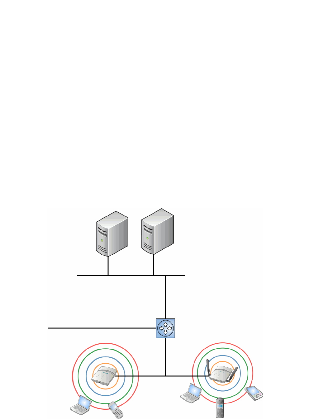
Conventional Wireless LANs
1-2 Overview of the Enterasys Wireless Convergence Software Solution
• AssignseachwirelessdevicetoaVNSwhenitconnects
•Routestrafficfromwirelessdevices,usingVNS,tothewirednetwork
•Appliesfilteringpoliciestothewirelessdevicesession
•Providessessionloggingandaccountingcapability
Conventional Wireless LANs
Wirelesscommunicationbetweenmultiplecomputersrequiresthateachcomputerbeequipped
withareceiver/transmitter—aWLANNetworkInterfaceCard(NIC)—capableofexchanging
digitalinformationoveracommonradiofrequency.Thisiscalledanadhocnetwork
configuration.Anadhocnetworkconfigurationallowswirelessdevicestocommunicatetogether.
Thissetupisdefinedasanindependentbasicserviceset(IBSS).
Analternativetotheadhocconfigurationistheuseofanaccesspoint.Thismaybeadedicated
hardwarebridgeoracomputerrunningspecialsoftware.Computersandotherwirelessdevices
communicatewitheachotherthroughthisaccesspoint.The802.11standarddefinesaccesspoint
communicationsasdevicesthatallowwirelessdevicestocommunicatewithadistribution
system.Thissetupisdefinedasabasicserviceset(BSS)orinfrastructurenetwork.
Toallowthewirelessdevicestocommunicatewithcomputersonawirednetwork,theaccess
pointsmustbeconnectedtothewirednetworkprovidingaccesstothenetworkedcomputers.
Thistopologyiscalledbridging.Withbridging,securityandmanagementscalabilityisoftena
concern.
Figure 1-1 Standard Wireless Network Solution Example
DHCP Server
RADIUS
Authentication
Server
Ethernet Router/Switch
Wireless AP
Wireless AP
Ethernet
Wireless
Devices Wireless
Devices
DRAFT

Elements of the Enterasys Wireless Convergence Software Solution
User Guide, V8.01 1-3
Thewirelessdevicesandthewirednetworkscommunicatewitheachotherusingstandard
networkingprotocolsandaddressingschemes.Mostcommonly,InternetProtocol(IP)addressing
isused.
Elements of the Enterasys Wireless Convergence Software
Solution
TheEnterasysWirelessConvergenceSoftwaresolutionconsistsoftwodevices:
•EnterasysWirelessController
•WirelessAPs
ThisarchitectureallowsasingleEnterasysWirelessControllertocontrolmanyWirelessAPs,
makingtheadministrationandmanagementoflargenetworksmucheasier.
TherecanbeseveralEnterasysWirelessControllersinthenetwork,eachwithasetofregistered
WirelessAPs.TheEnterasysWirelessControllerscanalsoactasbackupstoeachother,providing
stablenetworkavailability.
InadditiontotheEnterasysWirelessControllersandWirelessAPs,thesolutionrequiresthree
othercomponents,allofwhicharestandardforenterpriseandserviceprovidernetworks:
•RADIUSServer(RemoteAccessDial‐InUserService)orotherauthenticationserver
•DHCPServer(DynamicHostConfigurationProtocol).IfyoudonothaveaDHCPServeron
yournetwork,youcanenablethelocalDHCPServerontheEnterasysWirelessController.
ThelocalDHCPServerisusefulasageneralpurposeDHCPServerforsmallsubnets.For
moreinformation,seeStep 11of“SettingUptheDataPorts”onpage 2‐16.
•SLP(ServiceLocationProtocol)
DRAFT
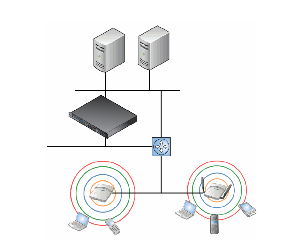
Elements of the Enterasys Wireless Convergence Software Solution
1-4 Overview of the Enterasys Wireless Convergence Software Solution
Figure 1-2 Enterasys Wireless Controller Solution
AsillustratedinFigure 1‐2,theEnterasysWirelessControllerappearstotheexistingnetworkasif
itwereanaccesspoint,butinfactoneEnterasysWirelessControllercontrolsmanyWirelessAPs.
TheEnterasysWirelessControllerhasbuilt‐incapabilitiestorecognizeandmanagetheWireless
APs.TheEnterasysWirelessController:
•Acti
vatestheWirelessAPs
•EnablesWirelessAPstoreceivewirelesstrafficfromwirelessdevices
•ProcessesthedatatrafficfromtheWirelessAPs
•Forwardsorroutestheprocesseddatatrafficouttothenetwork
• Authenticatesrequestsandappliesaccesspolicies
SimplifyingtheWirelessAPsmakesthemcost‐effective,easytomanage,andeasytodeploy.
PuttingcontrolonanintelligentcentralizedEnterasysWirelessControllerenables:
• Centralizedconfiguration,management,reporting,andmaintenance
•Highsecurity
•Flexibilitytosuitenterprise
•ScalableandresilientdeploymentswithafewEnterasysWirelessControllerscontrolling
hundredsofWirelessAPs
DHCP Server
RADIUS
Authentication
Server
Ethernet
Router/Switch
Wireless AP
Wireless AP
Ethernet
Wireless
Devices
Wireless
Devices
Wireless
Controller
DRAFT

Elements of the Enterasys Wireless Convergence Software Solution
User Guide, V8.01 1-5
TheEnterasysWirelesssystem:
•ScalesuptoEnterprisecapacity—EnterasysWirelessControllersarescalable:
– C5110—Upto525APs
– C4110—Upto250APs
–C20—Upto32APs
–C25—Upto48APs
– V2110—Upto120APs
Inturn,eachWirelessAPcanhandleupto254wirelessdevices,witheachradiosupportinga
maximumof127.WithadditionalEnterasysWirelessControllers,thenumberofwireless
devicesthesolutioncansupportcanreachintothethousands.
•Integrateswithexistingnetwork—AEnterasysWirelessControllercanbeaddedtoan
existingenterprisenetworkasanewnetworkdevice,greatlyenhancingitscapabilitywithout
interferingwithexistingfunctionality.IntegrationoftheEnterasysWirelessControllersand
WirelessAPsdoesnotrequireanyre‐configurationoftheexistinginfrastructure(forexample,
VLANs).
•IntegrateswiththeEnterasysNetSightSuiteofproducts.Formoreinformation,see
“EnterasysNetSightSuiteIntegration”onpage 1‐6.
Plug‐inapplicationsinclude:
–A
utomatedSecurityManager
–InventoryManager
–NACManager
–PolicyControlConsole
–PolicyManager
•Offerscentralizedmanagementandcontrol—AnadministratoraccessestheEnterasys
WirelessControllerinitscentralizedlocationtomonitorandadministertheentirewireless
network.FromtheEnterasysWirelessControllertheadministratorcanrecognize,configure,
andmanagetheWirelessAPsanddistributenewsoftwarereleases.
•ProvideseasydeploymentofWirelessAPs—TheinitialconfigurationoftheWirelessAPson
thecentralizedEnterasysWirelessControllercanbedonewithanautomatic“discovery”
technique.
•Providessecurityviauserauthentication—Usesexistingauthentication(AAA)serversto
authenticateandauthorizeusers.
•Providessecurityviafiltersandprivileges—Usesvirtualnetworkingtechniquestocreate
separatevirtualnetworkswithdefinedauthenticationandbillingservices,accesspolicies,and
privileges.
•Supportsseamlessmobilityandroaming—Supportsseamlessroamingofawirelessdevice
fromoneWirelessAPtoanotheronthesameEnterasysWirelessControlleroronadifferent
EnterasysWirelessController.
•Integratesthird‐partyaccesspoints—Usesacombinationofnetworkroutingand
authenticationtechniques.
•Preventsroguedevices—Unauthorizedaccesspointsaredetectedandidentifiedaseither
harmlessordangerousrogueAPs.
•Providesaccountingservices—Logswirelessusersessions,usergroupactivity,andother
activityreporting,enablingthegenerationofconsolidatedbillingrecords.
DRAFT

Elements of the Enterasys Wireless Convergence Software Solution
1-6 Overview of the Enterasys Wireless Convergence Software Solution
•Offerstroubleshootingcapability—Logssystemandsessionactivityandprovidesreports
toaidintroubleshootinganalysis.
•OffersdynamicRFmanagement—AutomaticallyselectschannelsandadjustsRadio
Frequency(RF)signalpropagationandpowerlevelswithoutuserintervention.
Enterasys NetSight Suite Integration
TheEnterasysWirelessConvergenceSoftwaresolutionnowintegrateswiththeEnterasys
NetSightSuiteofproducts.TheEnterasysNetSightSuiteofproductsprovidesacollectionoftools
tohelpyoumanagenetworks.Itsclient/serverarchitectureletsyoumanageyournetworkfroma
singleworkstationor,fornetworksofgreatercomplexity,fromoneormoreclientworkstations.It
isdesignedtofacilitatespecificnetworkmanagementtaskswhilesharingdataandproviding
commoncontrolsandaconsistentuserinterface.Formoreinformation,seehttp://
www.enterasys.com/products/visibility‐control/index.aspx
TheNetSightSuiteisafamilyofproductscomprisedofNetSightConsoleandasuiteofplug‐in
applications,including:
•AutomatedSecurityManager—AutomatedSecurityManagerisauniquethreatresponse
solutionthattranslatessecurityintelligenceintosecurityenforcement.Itprovides
sophisticatedidentificationandmanagementofthreatsandvulnerabilities.Forinformation
onhowtheEnterasysWirelessConvergenceSoftwaresolutionintegrateswiththeAutomated
SecurityManagerapplication,seetheEnterasysWirelessConvergenceSoftwareMaintenance
Guide.
•InventoryManager—InventoryManagerisatoolforefficientlydocumentingandupdating
thedetailsoftheever‐changingnetwork.ForinformationonhowtheEnterasysWireless
ConvergenceSoftwaresolutionintegrateswiththeAutomatedSecurityManagerapplication,
seetheEnterasysWirelessConvergenceSoftwareMaintenanceGuide.
•NACManager—NACManagerisaleading‐edgeNACsolutiontoensureonlytheright
usershaveaccesstotherightinformationfromtherightplaceattherighttime.TheEnterasys
NACsolutionperformsmulti‐user,multi‐methodauthentication,vulnerabilityassessment
andassistedremediation.ForinformationonhowtheEnterasysWirelessConvergence
SoftwaresolutionintegrateswiththeEnterasysNACsolution,see“NACintegrationwith
EnterasysWirelessWLAN”onpage 1‐12.
•PolicyManager—PolicyManagerrecognizestheEnterasysWirelessControllersuiteas
policycapabledevicesthatacceptpartialconfigurationfromPolicyManager.Currentlythis
integrationispartialinthesensethatNetSightisunabletocreateWLANservicesdirectly;The
WLANservicesneedtobedirectlyprovisionedonthecontrollerandarerepresentedtoPolicy
Manageraslogicalports.TheEnterasysWirelessControllerallowsPolicyManagerto:
– AttachTopologies(assignVLANtoport)totheEnterasysWirelessControllerphysical
ports(Console).
– Attachpolicytothelogicalports(WLANService/SSID),
– AssignaDefaultRole/PolicytoaWLANService,thuscreatingtheVNS.
–Performauthenticationoperationswhichcanthenreferencedefinedpoliciesforstation‐
specificpolicyenforcement.
Thiscanbeseenasathreestepprocess:
a. Deploythecontrollerandperformlocalconfiguration
‐TheEnterasysWirelessControllershipswithadefaultSSID,attachedbydefaulttoall
APradios,whenenabled.
DRAFT

Enterasys Wireless Convergence Software and Your Network
User Guide, V8.01 1-7
‐UsethebasicinstallationwizardtocompletetheEnterasysWirelessController
configuration.
b. UsePolicyManagerto:
‐PushtheVLANlisttotheEnterasysWirelessController(Topologies)
‐AttachVLANstoEnterasysWirelessControllerphysicalports(Console‐Complete
Topologydefinition)
‐PushRADIUSserverconfigurationtotheEnterasysWirelessController
‐PushpolicydefinitionstotheEnterasysWirelessController
‐AttachthedefaultpolicytocreateaVNS
c. Finetunecontrollersettings.Forexample,configuringfilteringatAPsandEnterasys
WirelessControllerforabridgedatcontrollerorroutedtopologiesandassociatedVNSs.
Enterasys Wireless Convergence Software and Your Network
ThissectionisasummaryofthecomponentsoftheEnterasysWirelessConvergenceSoftware
solutiononyourenterprisenetwork.Thefollowingaredescribedindetailinthisguide,unless
otherwisestated:
•EnterasysWirelessController—Arack‐mountablenetworkdevicethatprovidescentralized
controloverallaccesspointsandmanagesthenetworkassignmentofwirelessdeviceclients
associatingthroughaccesspoints.
•WirelessAP—AwirelessLANfitaccesspointthatcommunicateswithaEnterasysWireless
Controller.
•RADIUSServer(RemoteAccessDial‐InUserService)(RFC2865),orotherauthentication
server—AnauthenticationserverthatassignsandmanagesIDandPasswordprotection
throughoutthenetwork.Usedforauthenticationofthewirelessusersineither802.1xor
CaptivePortalsecuritymodes.TheRADIUSServersystemcanbesetupforcertainstandard
attributes,suchasfilterID,andfortheVendorSpecificAttributes(VSAs).Inaddition,
RADIUSDisconnect(RFC3576)whichpermitsdynamicadjustmentofuserpolicy(user
disconnect)issupported.
•DHCPServer(DynamicHostConfigurationProtocol)(RFC2131)—Aserverthatassigns
dynamicallyIPaddresses,gateways,andsubnetmasks.IPaddressassignmentforclientscan
bedonebytheDHCPserverinternaltotheEnterasysWirelessController,orbyexisting
serversusingDHCPrelay.ItisalsousedbytheWirelessAPstodiscoverthelocationofthe
EnterasysWirelessControllerduringtheinitialregistrationprocessusingOptions43,60,and
Option78.Options43and60specifythevendorclassidentifier(VCI)andvendorspecific
information.Option78specifiesthelocationofoneormoreSLPDirectoryAgents.ForSLP,
DHCPshouldhaveOption78enabled.
•ServiceLocationProtocol(SLP)(SLPRFC2608)—ClientapplicationsareUserAgentsand
servicesthatareadvertisedbyaServiceAgent.Inlargerinstallations,aDirectoryAgent
collectsinformationfromServiceAgentsandcreatesacentralrepository.TheEnterasys
solutionreliesonregistering“Enterasys”asanSLPServiceAgent.
•DomainNameServer(DNS)—Aserverusedasanalternatemechanism(ifpresentonthe
enterprisenetwork)fortheautomaticdiscoveryprocess.EnterasysWirelessController,
AccessPointsandConvergenceSoftwarereliesontheDNSforLayer3deploymentsandfor
Note: Complete information about integration with Policy Manager is outside the scope of this
document.
DRAFT

Enterasys Wireless Convergence Software and Your Network
1-8 Overview of the Enterasys Wireless Convergence Software Solution
staticconfigurationofWirelessAPs.ThecontrollercanberegisteredinDNS,toprovideDNS
assistedAPdiscovery.Inaddition,DNScanalsobeusedforresolvingRADIUSserver
hostnames.
•WebAuthenticationServer—AserverthatcanbeusedforexternalCaptivePortaland
externalauthentication.TheEnterasysWirelessControllerhasaninternalCaptiveportal
presentationpage,whichallowsWebauthentication(Webredirection)totakeplacewithout
theneedforanexternalCaptivePortalserver.
•RADIUSAccountingServer(RemoteAccessDial‐InUserService)(RFC2866)—Aserverthat
isrequiredifRADIUSAccountingisenabled.
•SimpleNetworkManagementProtocol(SNMP)—AManagerServerthatisrequiredif
forwardingSNMPmessagesisenabled.
•Networkinfrastructure—TheEthernetswitchesandroutersmustbeconfiguredtoallow
routingbetweenthevariousservicesnotedabove.Routingmustalsobeenabledbetween
multipleEnterasysWirelessControllersforthefollowingfeaturestooperatesuccessfully:
– Availability
– Mobility
– Mitigatorfordetectionofrogueaccesspoints
Somefeaturesalsorequirethedefinitionofstaticroutes.
•WebBrowser—AbrowserprovidesaccesstotheEnterasysWirelessControllerManagement
userinterfacetoconfiguretheEnterasysWirelessConvergenceSoftware.
•SSHEnabledDevice—AdevicethatsupportsSecureShell(SSH)isusedforremote(IP)shell
accesstothesystem.
•ZoneIntegrity—TheZoneintegrityserverenhancesnetworksecuritybyensuringclients
accessingyournetworkarecompliantwithyoursecuritypoliciesbeforegainingaccess.Zone
IntegrityRelease5issupported.
Network Traffic Flow
Figure 1‐3illustratesasimpleconfigurationwithasingleEnterasysWirelessControllerandtwo
WirelessAPs,eachsupportingawirelessdevice.ARADIUSserveronthenetworkprovides
authentication,andaDHCPserverisusedbytheWirelessAPstodiscoverthelocationofthe
EnterasysWirelessControllerduringtheinitialregistrationprocess.Networkinter‐connectivityis
providedbytheinfrastructureroutingandswitchingdevices.
DRAFT
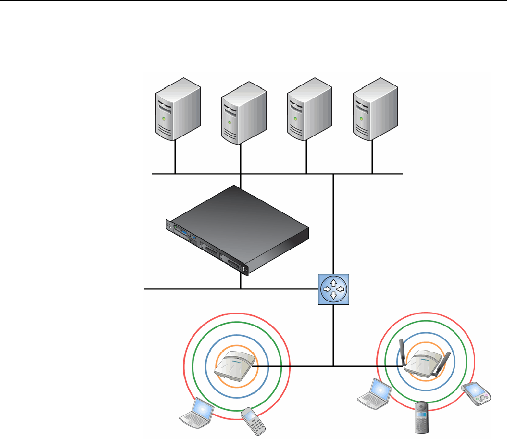
Enterasys Wireless Convergence Software and Your Network
User Guide, V8.01 1-9
Figure 1-3 Traffic Flow Diagram
EachwirelessdevicesendsIPpacketsinthe802.11standardtotheWirelessAP.TheWirelessAP
usesaUDP(UserDatagramProtocol)basedtunnellingprotocol.Intunneledmodeofoperation,it
encapsulatesthepacketsandforwardsthemtotheEnterasysWirelessController.TheEnterasys
WirelessControllerdecapsulatesthepacketsandroutesthesetodestinationsonthenetwork.Ina
typicalconfiguration,accesspointscanbeconfiguredtolocallybridgetraffic(toaconfigured
VLAN)directlyattheirnetworkpointofattachment.
TheEnterasysWirelessControllerfunctionslikeastandardL3routerorL2switch.Itisconfigured
toroutethenetworktrafficassociatedwithwirelessconnectedusers.TheEnterasysWireless
Controllercanalsobeconfiguredtosimplyforwardtraffictoadefaultorstaticrouteifdynamic
routingisnotpreferredoravailable.
Network Security
TheEnterasysWirelessConvergenceSoftwaresystemprovidesfeaturesandfunctionalityto
controlnetworkaccess.Thesearebasedonstandardwirelessnetworksecuritypractices.
Currentwirelessnetworksecuritymethodsprovideprotection.Thesemethodsinclude:
•SharedKeyauthenticationthatreliesonWiredEquivalentPrivacy(WEP)keys
Packet transmission
Control and Routing
> HWC authenticates wireless user
> HWC forwards IP packet to wired
network
Tunnelling
> AP sends data traffic to HWC
through UDP tunnel called WASSP
> HWC controls Wireless AP
through WASSP tunnel
> Using WASSP tunnels, HWC
allows wireless clients to roam to
Wireless APs on different HWCs
802.11 packet transmission
802.11 beacon and probe, wireless
device associates
with a Wireless AP
by its SSID
Wireless Devices
Router/Switch
Wireless
Controller
RADIUS
Authentication
Server External
CP Server
External Web
Authentication
Server
Wireless APs
DHCP
Server
DRAFT

Enterasys Wireless Convergence Software and Your Network
1-10 Overview of the Enterasys Wireless Convergence Software Solution
•OpenSystemthatreliesonServiceSetIdentifiers(SSIDs)
• 802.1xthatiscompliantwithWi‐FiProtectedAccess(WPA)
•CaptivePortalbasedonSecureSocketsLayer(SSL)protocol
TheEnterasysWirelessConvergenceSoftwaresystemprovidesthecentralizedmechanismby
whichthecorrespondingsecurityparametersareconfiguredforagroupofusers.
•WiredEquivalentPrivacy(WEP)isasecurityprotocolforwirelesslocalareanetworks
definedinthe802.11bstandard
•Wi‐FiProtectedAccessversion1(WPA1™)withTemporalKeyIntegrityProtocol(TKIP)
•Wi‐FiProtectedAccessversion2(WPA2™)withAdvancedEncryptionStandard(AES)and
CounterModewithCipherBlockChainingMessageAuthenticationCode(CCMP)
Authentication
TheEnterasysWirelessControllerreliesonaRADIUSserver,orauthenticationserver,onthe
enterprisenetworktoprovidetheauthenticationinformation(whethertheuseristobeallowedor
deniedaccesstothenetwork).ARADIUSclientisimplementedtointeractwithinfrastructure
RADIUSservers.
TheEnterasysWirelessControllerprovidesauthenticationusing:
•Capti
vePortal—abrowser‐basedmechanismthatforcesuserstoaWebpage
•RADIUS(usingIEEE802.1x)
The802.1xmechanismisastandardforauthenticationdevelopedwithinthe802.11standard.This
mechanismisimplementedatthewirelessport,blockingalldatatrafficbetweenthewireless
deviceandthenetworkuntilauthenticationiscomplete.Authenticationby802.1xstandarduses
ExtensibleAuthenticationProtocol(EAP)forthemessageexchangebetweentheEnterasys
WirelessControllerandtheRADIUSserver.
When802.1xisusedforauthentication,theEnterasysWirelessControllerprovidesthecapability
todynamicallyassignper‐wireless‐deviceWEPkeys(calledpersessionWEPkeysin802.11).In
thecaseofWPA,theEnterasysWirelessControllerisnotinvolvedinkeyassignment.Instead,the
controllerisinvolvedintheinformationexchangebetweenRADIUSserverandtheuser’swireless
devicetonegotiatetheappropriatesetofkeys.WithWPA2thematerialexchangeproducesa
PairwiseMasterKeywhichisusedbytheAPandtheusertoderivetheirtemporalkeys.(Thekeys
changeovertime.)
TheEnterasysWirelessConvergenceSoftwaresolutionprovideaRADIUSredundancyfeature
thatenablesyoutodefineafailoverRADIUSserverintheeventthattheactiveRADIUSserver
becomesunresponsive.
Privacy
Privacyisamechanismthatprotectsdataoverwirelessandwirednetworks,usuallyby
encryptiontechniques.
EnterasysWirelessConvergenceSoftwaresupportstheWiredEquivalentPrivacy(WEP)standard
commontoconventionalaccesspoints.
ItalsoprovidesWi‐FiProtectedAccessversion1(WPAv.1)encryption,basedonPairwiseMaster
Key(PMK)andTemporalKeyIntegrityProtocol(TKIP).Themostsecureencryptionmechanism
isWPAversion2,usingAdvancedEncryptionStandard(AES).
DRAFT
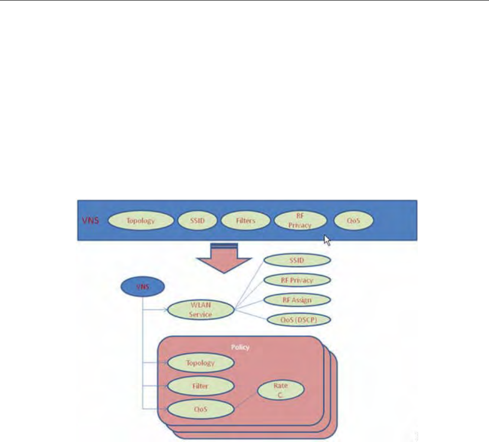
Enterasys Wireless Convergence Software and Your Network
User Guide, V8.01 1-11
Virtual Network Services
VirtualNetworkServices(VNS)provideaversatilemethodofmappingwirelessnetworkstothe
topologyofanexistingwirednetwork.
InreleasespriortoV7.0,aVNSwasacollectionofoperationalentities.StartingwithReleaseV7.0,
aVNSbecomesthebindingofreusablecomponents:
•WLANServicecomponentsthatdefinetheradioattributes,privacyandauthentication
settings,andQoSattributesoftheVNS
•Policycomponentsthatdefinethetopology(typicallyaVLAN),filterrules,andClassof
Serviceappliedtothetrafficofastation.
Figure 1‐4illustratesthetransitionoftheconceptofaVNStoabindingofreusablecomponents.
Figure 1-4 VNS as a Binding of Reusable Components
WLANServicecomponentsandPolicycomponentscanbeconfiguredseparatelyandassociated
withaVNSwhentheVNSiscreatedormodified.Alternatively,theycanbeconfiguredduringthe
processofcreatingaVNS.
Additionally,PoliciescanbecreatedusingtheEnterasysNetSightPolicyManagerorNetSight
WirelessManagerandpushedtotheEnterasysWirelessController.Policyassignmentensures
thatthecorrecttopologyandtrafficbehaviorareappliedtoauserregardlessofWLANservice
usedorVNSassignment.
WhenVNScomponentsaresetupontheEnterasysWirelessController,amongotherthings,a
rangeofIPaddressesissetasidefortheEnterasysWirelessController’sDHCPservertoassignto
wirelessdevices.
IftheOSPFroutingprotocolisenabled,theEnterasysWirelessControlleradvertisestherouted
topologiesasreachablesegmentstothewirednetworkinfrastructure.Thecontrollerroutestraffic
betweenthewirelessdevicesandthewirednetwork.
DRAFT

Enterasys Wireless Convergence Software and Your Network
1-12 Overview of the Enterasys Wireless Convergence Software Solution
TheEnterasysWirelessControlleralsosupportsVLAN‐bridgedassignmentforVNSs.Thisallows
thecontrollertodirectlybridgethesetofwirelessdevicesassociatedwithaWLANservice
directlytoaspecifiedcoreVLAN.
EachEnterasysWirelessControllermodelcansupportaspecifiednumberofactiveVNSs,as
listedbelow:
• C5110—Upto128VNSs
• C4110—Upto64VNSs
•C20—Upto8VNSs
•C25—Upto16VNSs
• V2110—Upto48VNSs
TheWirelessAPradioscanbeassignedtoeachoftheconfiguredWLANservicesand,therefore,
VNSsinasystem.EachWirelessAPcanbethesubjectof16serviceassignments—8assignments
perradio—whichcorrespondstothenumberofSSIDsitcansupport.Oncearadiohasall8slots
assigned,itisnolongereligibleforfurtherassignment.
NAC integration with Enterasys Wireless WLAN
EnterasysWirelessWLANsupportsintegrationwithaNAC(NetworkAdmissionControl)
Gateway.TheNACGatewaycanprovideyournetworkwithauthentication,registration,
assessment,remediation,andaccesscontrolformobileusers.
NACGatewayintegrationwithEnterasysWirelessWLANsupportsSSIDVNSswhenusedin
conjunctionwithMAC‐basedexternalcaptiveportalauthentication.
Figure 1‐5andTable 1‐1depictthetopologyandworkflowrelationshipbetweenEnterasys
WirelessWLANthatisconfiguredforexternalcaptiveportalandaNACGateway.Withthis
configuration,theNACGatewayactslikeaRADIUSproxyserver.Analternativeistoconfigure
theNACGatewaytoperformMAC‐basedauthenticationitself,usingitsowndatabaseofMAC
addressesandpermissions.Formoreinformation,see“CreatingaNACVNSUsingtheVNS
Wizard”onpage 7‐19.
DRAFT
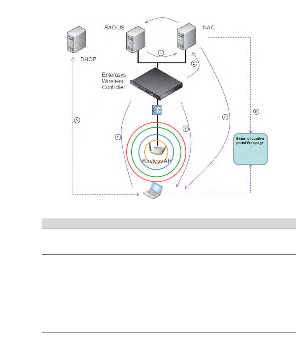
Enterasys Wireless Convergence Software and Your Network
User Guide, V8.01 1-13
Figure 1-5 WLAN and NAC Integration with External Captive Portal Authentication
Table 1-1 WLAN and NAC Integration Steps
Step Description
1 The client laptop connects to the Wireless AP.
The Wireless AP determines that authentication is required, and sends an association
request to the Enterasys Wireless Controller.
2 The Enterasys Wireless Controller forwards to the NAC Gateway an access-request
message for the client laptop, which is identified by its MAC address.
The NAC Gateway forwards the access-request to the RADIUS server. The NAC Gateway
acts like a RADIUS proxy server.
3 The RADIUS server evaluates the access-request and sends an Access-Accept message
back to the NAC.
The NAC receives the access-accept packet. Using its local database, the NAC determines
the correct policy to apply to this client laptop and updates the access-accept packet with the
policy assignment. The updated Access-Accept message is forwarded to the Enterasys
Wireless Controller and Wireless AP.
4 The Enterasys Wireless Controller and Wireless AP apply policy against the client laptop
accordingly. The Enterasys Wireless Controller assigns a set of filters to the client laptop’s
session and the Wireless AP allows the client laptop access to the network.
5 The client laptop interacts with a DHCP server to obtain an IP address.
DRAFT

Enterasys Wireless Convergence Software and Your Network
1-14 Overview of the Enterasys Wireless Convergence Software Solution
VNS Components
Thedistinctconstituenthigh‐levelconfigurableumbrellaelementsofaVNSare:
• Topology
•Policy
•ClassesofService
•WLANService
Topology
TopologiesrepresentthenetworkswithwhichtheEnterasysWirelessControlleranditsAPs
interact.Themainconfigurableattributesofatopologyare:
•Name‐astringofalphanumericcharactersdesignatedbytheadministrator.
•VLANID‐theVLANidentifierasspecifiedintheIEEE802.1Qdefinition.
•VLANtaggingoptions.
•PortofpresenceforthetopologyontheEnterasysWirelessController.(Thisattributeisnot
requiredforRoutedandBridgedatAPtopologies.)
•Interface.ThisattributeistheIP(L3)addressassignedtotheEnterasysWirelessControlleron
thenetworkdescribedbythetopology.(Optional.)
•Type.Thisattributedescribeshowtrafficisforwardedonthetopology.Optionsare:
– “Physical”‐thetopologyisthenativetopologyofadataplaneanditrepresentstheactual
Ethernetports
– “Management”‐thenativetopologyoftheEnterasysWirelessControllermanagement
port
–“Routed”‐thecontrolleristheroutinggatewayfortheroutedtopology.
–“BridgedatController”‐theusertrafficisbridged(intheL2sense)betweenwireless
clientsandthecorenetworkinfrastructure.
6 Eventually the client laptop uses its Web browser to access a Website.
• The Enterasys Wireless Controller determines that the target Website is blocked and that
the client laptop still requires authentication.
• The Enterasys Wireless Controller sends an HTTP redirect to the client laptop’s browser.
The redirect sends the browser to the Web server on the NAC Gateway.
• The NAC displays an appropriate Web page in the client laptop’s browser. The contents of
the page depend on the current policy assignment (enterprise, remediation, assessing,
quarantine, or unregistered) for the MAC address.
7 When the NAC determines that the client laptop is ready for a different policy assignment, it
sends a ‘disconnect message’ (RFC 3576) to the Enterasys Wireless Controller.
When the Enterasys Wireless Controller receives the ‘disconnect message’ sent by the NAC,
the Enterasys Wireless Controller terminates the session for the client laptop.
The Enterasys Wireless Controller forwards the command to terminate the client laptop’s
session to the Wireless AP, which disconnects the client laptop.
Table 1-1 WLAN and NAC Integration Steps (continued)
Step Description
DRAFT

Enterasys Wireless Convergence Software and Your Network
User Guide, V8.01 1-15
–“BridgedatAP”‐theusertrafficisbridgedlocallyattheAPwithoutbeingredirectedto
theEnterasysWirelessController.
•ExceptionFilters.SpecifieswhichtraffichasaccesstotheEnterasysWirelessControllerfrom
thewirelessclientsortheinfrastructurenetwork.
• Certificates.
•Multicastfilters.Definesthemulticastgroupsthatareallowedonaspecifictopologysegment.
Policy
APolicyisacollectionofattributesandrulesthatdetermineactionstakenusertrafficaccessesthe
wirednetworkthroughtheWLANservice(associatedtotheWLANServiceʹsSSID).Depending
uponitstype,aVNScanhavebetweenoneandthreeAuthorizationPoliciesassociatedwithit:
1. Defaultnon‐authorizedpolicy—Thisisamandatorypolicythatcoversalltrafficfrom
stationsthathavenotauthenticated.Attheadministratorʹsdiscretionthedefaultnon‐
authorizedpolicycanbeappliedtothetrafficofauthenticatedstationsaswell.
2. Defaultauthorizedpolicy—Thisisamandatorypolicythatappliestothetrafficof
authenticatedstationsforwhichnootherpolicywasexplicitlyspecified.Itcanbethesameas
thedefaultnon‐authorizedpolicy.
3. ThirdpartyAPpolicy—ThispolicyappliestothelistofMACaddressescorrespondingtothe
wiredinterfacesofthirdpartyAPsspecificallydefinedbytheadministratortobeproviding
theRFaccessasanAPWLANService.Thispolicyisonlyrelevantwhenappliedtothirdparty
APWLANServices.
Classes of Service
Ingeneral,ClassofService(CoS)referstoasetofattributesthatdefinetheimportanceofaframe
whileitisforwardedthroughthenetworkrelativetootherpackets,andtothemaximum
throughputpertimeunitthatastationorportassignedtoaspecificpolicyispermitted.TheCoS
definesactionstobetakenwhenratelimitsareexceeded.
AllincomingpacketsmayfollowthesestepstodetermineaCoS:
• Classification‐identifiesthefirstmatchingrulethatdefinesaCoS.
•Marking‐modifiestheL2802.1pand/orL3ToSbasedonCoSdefinition.
• Ratelimiting(drop)isset.
ThesystemlimitforthenumberofCoSprofilesonacontrollerisidenticaltothenumberof
policies.Forexample,themaximumnumberofCoSprofilesonaC5110is512.
WLAN Services
AWLANServicerepresentsalltheRF,authenticationandQoSattributesofawirelessaccess
serviceofferedbytheEnterasysWirelessControlleranditsAPs.AWLANServicecanbeoneof
thefollowingtypes:
• Standard—Aconventionalservice.OnlyAPsrunningEnterasysWirelesssoftwarecanbe
partofthisWLANService.ThistypeofservicecanbeusedasaBridgedatController,
BridgedatAP,orRoutedTopology.Thistypeofserviceprovidesaccessformobilestations.
PoliciescanbeassociatedwiththistypeofWLANservicetocreateaVNS.
•ThirdPartyAP—AWirelessServiceofferedbythirdpartyAPs.Thistypeofserviceprovides
accessformobilestations.PoliciescanbeassignedtothistypeofWLANservicetocreatea
VNS.
DRAFT

Enterasys Wireless Convergence Software and Your Network
1-16 Overview of the Enterasys Wireless Convergence Software Solution
• DynamicMeshandWDS(StaticMesh)—ThisistoconfigureagroupofAPsorganizedintoa
hierarchyforpurposesofprovidingaWirelessDistributionService.Thistypeofserviceisin
essenceawirelesstrunkingserviceratherthanaservicethatprovidesaccessforstations.As
such,thisservicecannothavepoliciesattachedtoit.
•Re
mote—Aservicethatresidesontheedge(foreign)EnterasysWirelessController.Pairinga
remoteservicewitharemoteableserviceonthedesignatedhomeEnterasysWireless
ControllerallowsyoutoprovisioncentralizedWLANServicesinthemobilitydomain.Thisis
knownascentralizedmobility.
AsofReleaseV7.0,thecomponentsofaWLANServicemaptothecorrespondingcomponentsof
aVNSinpreviousreleases.TheexceptionisthatWLANServicesarenotclassifiedasSSID‐based
orAAA‐based,aswasthecaseinpreviousreleases.Instead,theadministratormakesanexplicit
choiceofthetypeofauthenticationtouseontheWLANService.Ifhischoiceofauthentication
optionconflictswithanyofhisotherauthenticationorprivacychoices,theWLANServicecannot
beenabled.
Routing
RoutingcanbeusedontheEnterasysWirelessControllertosupporttheVNSdefinitions.
ThroughtheuserinterfaceyoucanconfigureroutingontheEnterasysWirelessControllertouse
oneofthefollowingroutingtechniques:
•Staticroutes—UsestaticroutestosetthedefaultrouteofaEnterasysWirelessControllerso
thatlegitimatewirelessdevicetrafficcanbeforwardedtothedefaultgateway.
•OpenShortestPathFirst(OSPF,version2)(RFC2328)—UseOSPFtoallowtheEnterasys
WirelessControllertoparticipateindynamicrouteselection.OSPFisaprotocoldesignedfor
mediumandlargeIPnetworkswiththeabilitytosegmentroutesintodifferentareasby
routinginformationsummarizationandpropagation.StaticRoutedefinitionandOSPF
dynamiclearningcanbecombined,andtheprecedenceofastaticroutedefinitionover
dynamicrulescanbeconfiguredbyselectingorclearingtheOverridedynamicroutesoption
checkbox.
•Next‐hoprouting—Usenext‐hoproutingtospecifyauniquegatewaytowhichtrafficona
VNSisforwarded.Defininganext‐hopforaVNSforcesallthetrafficintheVNStobe
forwardedtotheindicatednetworkdevice,bypassinganyroutingdefinitionsofthe
controllerʹsroutetable.
Mobility and Roaming
Intypicalsimpleconfigurations,APsaresetupasbridgesthatbridgewirelesstraffictothelocal
subnet.Inbridgingconfigurations,theuserobtainsanIPaddressfromthesamesubnetastheAP,
assumingnoVLANtrunkingfunctionality.IftheuserroamsbetweenAPsonthesamesubnet,itis
abletokeepusingthesameIPaddress.However,iftheuserroamstoanotherAPoutsideofthat
subnet,itsIPaddressisnolongervalid.TheuserʹsclientdevicemustrecognizethattheIPaddress
ithasisnolongervalidandre‐negotiateanewoneonthenewsubnet.Thismechanismdoesnot
mandateanyactionontheuser.Therecoveryprocedureisentirelyclientdevicedependent.Some
clientsautomaticallyattempttoobtainanewaddressonroam(whichaffectsroaminglatency),
whileotherswillholdontotheirIPaddress.ThislossofIPaddresscontinuityseriouslyaffectsthe
clientʹsexperienceinthenetwork,becauseinsomecasesitcantakeminutesforanewaddressto
benegotiated.
TheEnterasysWirelessConvergenceSoftwaresolutioncentralizestheuserʹsnetworkpointof
presence,thereforeabstractinganddecouplingtheuserʹsIPaddressassignmentfromthatofthe
APslocationsubnet.ThatmeansthattheuserisabletoroamacrossanyAPwithoutlosingitsown
IPaddress,regardlessofthesubnetonwhichtheservingAPsaredeployed.
DRAFT

Enterasys Wireless Controller Product Family
User Guide, V8.01 1-17
Inaddition,aEnterasysWirelessControllercanlearnaboutotherEnterasysWirelessControllers
onthenetworkandthenexchangeclientsessioninformation.Thisenablesawirelessdeviceuser
toroamseamlesslybetweendifferentWirelessAPsondifferentEnterasysWirelessControllers.
Network Availability
TheEnterasysWirelessConvergenceSoftwaresolutionprovidesavailabilityagainstWirelessAP
outages,EnterasysWirelessControlleroutages,andevennetworkoutages.TheEnterasys
WirelessControllerinaVLANbridgedtopologycanpotentiallyallowtheusertoretaintheIP
addressinafailoverscenario,iftheVNS/VLANiscommontobothcontrollers.Forexample,
availabilityisprovidedbydefiningapairedcontrollerconfigurationbywhicheachpeercanactas
thebackupcontrollerfortheotherʹsAPs.APsinonecontrollerareallowedtofailoverand
registerwiththealternatecontroller.
IfanEnterasysWirelessControllerfails,allofitsassociatedWirelessAPscanautomaticallyswitch
overtoanotherEnterasysWirelessControllerthathasbeendefinedasthesecondaryorbackup
EnterasysWirelessController.IftheAPreboots,theoriginalEnterasysWirelessControlleris
restored.TheoriginalEnterasysWirelessControllerisrestoredifitisactive.However,activeAPs
willcontinuetobeconnectedtothefailovercontrolleruntiltheadministratorreleasesthemback
totheoriginalhomecontroller.
Quality of Service (QoS)
EnterasysWirelessConvergenceSoftwaresolutionprovidesadvancedQualityofService(QoS)
managementtoprovidebetternetworktrafficflow.Suchtechniquesinclude:
•WMM(Wi‐FiMultimedia)—WMMisenabledperWLANservice.TheEnterasysWireless
ControllerprovidescentralizedmanagementoftheAPfeatures.FordeviceswithWMM
enabled,thestandardprovidesmultimediaenhancementsforaudio,video,andvoice
applications.WMMshortensthetimebetweentransmittingpacketsforhigherprioritytraffic.
WMMispartofthe802.11estandardforQoS.InthecontextoftheEnterasysWireless
Solution,theToS/DSCPfieldisusedforclassificationandproperclassofservicemapping,
outputqueueselection,andprioritytagging.
•IPToS(TypeofService)orDSCP(DiffservCodepoint)—TheToS/DSCPfieldintheIP
headerofaframeindicatesthepriorityandclassofserviceforeachframe.TheIPTOSand/or
DSCPismaintainedandtransportedwithinCTP(CAPWAPTunnelingProtocol)bycopying
theuserIPQoSinformationtotheCTPheader—thisisreferredtoasAdaptiveQoS.
•RateControl—RateControlforusertrafficcanalsobeconsideredasanaspectofQoS.As
partofPolicydefinition,theusercanspecify(default)policythatincludesIngressandEgress
ratecontrol.IngressratecontrolappliestotrafficgeneratedbywirelessclientsandEgressrate
controlappliestotraffictargetingspecificwirelessclients.Thebit‐ratescanbeconfiguredas
partofgloballyavailableprofileswhichcanbeusedbyanyparticularconfiguration.Aglobal
defaultisalsodefined.
QualityofService(QoS)managementisalsoprovidedby:
• AssigninghighprioritytoaWLANservice
•AdaptiveQoS(automaticandalltimefeature)
• SupportforlegacydevicesthatuseSpectraLinkVoiceProtocol(SVP)forprioritizingvoice
traffic(configurable)
Enterasys Wireless Controller Product Family
TheEnterasysWirelessControllerisavailableinthefollowingproductfamilies:
DRAFT

Enterasys Wireless Controller Product Family
1-18 Overview of the Enterasys Wireless Convergence Software Solution
Table 1-2 Enterasys Wireless Controller Product Families
Enterasys Wireless Controller
Model Number Specifications
C5110 • Three data ports supporting up to 525 Wireless APs
– 2 fiber optic SR (10Gbps)
– 1 Ethernet port GigE
• One management port (Ethernet) GigE
• One console port (DB9 serial)
• Four USB ports — two on each front and back panel (only one
port active at a time)
• Redundant dual power supply unit
C4110 • Four GigE ports supporting up to 250 Wireless APs
• One management port (Ethernet) GigE
• One console port (DB9 serial)
• Four USB ports (only one active at a time)
• Redundant dual power supply unit
C20 • Two GigE ports supporting up to 32 Wireless APs
• One management port GigE
• One console port (USB control)
• One USB port
• Power supply standard (R)
C25 • Two GigE ports supporting up to 48 Wireless APs
• One management port GigE
• One console port (DB9 serial)
• One USB port
V2110 • Two GigE ports supporting up to 120 Wireless APs
• One management port GigE
• One console port (DB9 serial)
• Four USB ports (only one active at a time)
DRAFT
User Guide, V8.01 2-1
2
Configuring the Enterasys Wireless Controller
Thischapterdescribesthestepsinvolvedintheinitialconfigurationandsetup,oftheEnterasys
WirelessController,including:
System Configuration Overview
Thefollowingsectionprovidesahigh‐leveloverviewofthestepsinvolvedintheinitial
configurationofyoursystem:
1. Beforeyoubegintheconfigurationprocess,researchthetypeofWLANdeploymentthatis
required.Forexample,topologyandVLANIDs,SSIDs,securityrequirements,andfilter
policies.
2. Preparethenetworkservers.Ensurethattheexternalservers,suchasDHCPandRADIUS
servers(ifapplicable)areavailableandappropriatelyconfigured.
3. InstalltheEnterasysWirelessController.Formoreinformation,seethedocumentationfor
yourEnterasysWirelessController.
4. PerformthefirsttimesetupoftheEnterasysWirelessControlleronthephysicalnetwork,
whichincludesconfiguringtheIPaddressesoftheinterfacesontheEnterasysWireless
Controller.
– CreateanewphysicaltopologyandprovidetheIPaddresstobetherelevantsubnetpoint
ofattachmenttotheexistingnetwork.
–TomanagetheEnterasysWirelessControllerthroughtheinterfaceconfiguredabove,
selecttheMgmtcheckboxontheInterfacestab.
– ConfigurethedataportinterfacestobeonseparateVLANs,matchingtheVLANs
configuredinStep3above.Ensurealsothatthetaggedvs.untaggedstateisconsistent
withtheswitchportconfiguration.
For information about... Refer to page...
System Configuration Overview 2-1
Logging on to the Enterasys Wireless Controller 2-4
Wireless Assistant Home Screen 2-4
Working with the Basic Installation Wizard 2-7
Configuring the Enterasys Wireless Controller for the First Time 2-12
Using an AeroScout/Ekahau Location-Based Solution 2-53
Additional Ongoing Operations of the System 2-56
DRAFT

2-2 Configuring the Enterasys Wireless Controller
– Configurethetimezone.BecausechangingthetimezonerequiresrestartingtheEnterasys
WirelessController,Enterasysrecommendsthatyouconfigurethetimezoneduringthe
initialinstallationandconfigurationoftheEnterasysWirelessControllertoavoid
networkinterruptions.Formoreinformation,see“ConfiguringNetworkTime”on
page 2‐48.
–Applyanactivationkeyfile.Ifanactivationkeyisnotapplied,theEnterasysWireless
Controllerfunctionswithsomefeaturesenabledindemonstrationmode.Notallfeatures
areenabledindemonstrationmode.Forexample,mobilityisnotenabledandcannotbe
used.
5. ConfiguretheEnterasysWirelessControllerforremoteaccess:
–Setupanadministrationstation(laptop)onsubnet192.168.10.0/24.Bydefault,the
EnterasysWirelessControllerʹsManagementinterfaceisconfiguredwiththestaticIP
address192.168.10.1.
– ConfiguretheEnterasysWirelessController’smanagementinterface.
– Configurethedatainterfaces.
–SetuptheEnterasysWirelessControlleronthenetworkbyconfiguringthephysicaldata
ports.
– Configuretheroutingtable.
– ConfigurestaticroutesorOSPFparameters,ifappropriatetothenetwork.
Formoreinformation,see“ConfiguringtheEnterasysWirelessControllerfortheFirstTime”
onpage 2‐12.
6. Configurethetraffictopologiesyournetworkmustsupport.Topologiesrepresentthe
Controller’spointsofnetworkattachment,andthereforeVLANsandportassignmentsneed
tobecoordinatedwiththecorrespondingnetworkswitchports.Formoreinformation,see
“ConfiguringaBasicTopology”onpage 4‐2.
7. Configurepolicies.Policiesaretypicallyboundtotopologies.Policyapplicationassignsuser
traffictothecorrespondingnetworkpoint.
– Policiesdefineuseraccessrights(filteringorACL)
–Policesreferenceuserʹsratecontrolprofile.
Formoreinformation,see“ConfiguringPolicies”onpage 5‐1.
8. ConfigureWLANservices.
–DefineSSIDandprivacysettingsforthewirelesslink.
–SelectthesetofAPs/Radiosonwhichtheserviceispresent.
– Configurethemethodofcredentialauthenticationforwirelessusers(None,InternalCP,
ExternalCP,GuestPortal,802.1x[EAP])
Formoreinformation,see“ConfiguringWLANServices”onpage 6‐1.
9. CreatetheVNSs.
Caution: Whenever the licensed region changes on the Enterasys Wireless Controller, all Wireless
APs are changed to Auto Channel Select to prevent possible infractions to local RF regulatory
requirements. If this occurs, all manually configured radio channel settings will be lost.
Installing the new license key before upgrading will prevent the Enterasys Wireless Controller from
changing the licensed region, and in addition, manually configured channel settings will be
maintained. For more information, see the Enterasys Wireless Convergence Software Maintenance
Guide.
DRAFT

User Guide, V8.01 2-3
AVNSbindsaWLANServicetoaPolicythatwillbeusedfordefaultassignmentupona
user’snetworkattachment.
Youcancreatetopologies,policies,andWLANservicesfirst,beforeconfiguringaVNS,oryou
canselectoneofthewizards(suchastheVNSwizard),oryoucansimplyselecttocreatenew
VNS.
TheVNSpagethenallowsforin‐placecreationanddefinitionofanydependencyitmay
require,suchas:
– CreatinganewWLANService
– Creatinganewpolicy
– Creatinganewclassofservice(withinapolicy)
– Creatinganewtopology(withinapolicy)
– Creatingnewratecontrols,andotherClassofServiceparameters
Thedefaultshippingconfigurationdoesnotshipanypre‐configuredWLANServices,VNSs,
orPolicies.
10. Install,register,andassignAPstotheVNS.
– Confirmthelatestfirmwareversionisloaded.Formoreinformation,see“Performing
WirelessAPSoftwareMaintenance”onpage 3‐121.
–DeployWirelessAPstotheircorrespondingnetworklocations.
–Ifapplicable,configureadefaultAPtemplateforcommonradioassignment,whereby
APsautomaticallyreceivecompleteconfiguration.FortypicaldeploymentswhereallAPs
aretohavethesameconfiguration,thisfeaturewillexpeditedeployment,asanAPwill
automaticallyreceivefullconfiguration(includingVNS‐relatedassignments)uponinitial
registrationwiththeEnterasysWirelessController.Ifapplicable,modifythepropertiesor
settingsoftheWirelessAPs.Formoreinformation,seeChapter 3,Configuringthe
WirelessAP.
– ConnecttheWirelessAPstotheEnterasysWirelessController.
–OncetheWirelessAPsarepoweredon,theyautomaticallybegintheDiscoveryprocessof
theEnterasysWirelessController,basedonfactorsthatinclude:
‐TheirRegistrationmode(ontheWirelessAPRegistrationscreen)
‐Theenterprisenetworkservicesthatwillsupportthediscoveryprocess
DRAFT
Logging on to the Enterasys Wireless Controller
2-4 Configuring the Enterasys Wireless Controller
Logging on to the Enterasys Wireless Controller
1. LaunchyourWebbrowser(InternetExplorerversion6.0orhigher,orFireFox).
SeetheV8.01releasenotesforthesupportedWebbrowsers.
2. Inthebrowseraddressbar,typethefollowing,usingtheIPaddressofyourcontroller:
https://192.168.10.1:5825
ThislaunchestheWirelessAssistant.Theloginscreenisdisplayed.
3. IntheUserNamebox,typeyourusername.
4. InthePasswordbox,typeyourpassword.
5. ClickLogin.TheWirelessAssistantHomeScreenisdisplayed.
Wireless Assistant Home Screen
TheWirelessAssistantHomeScreenprovidesreal‐timestatusinformationonthecurrentstateof
thewirelessnetwork.Informationisgroupedundermultiplefunctionalareas(NetworkStatus,
Adminsessions,andsoon)andprovidesagraphicalrepresentationofactiveAPinformation
(suchasthenumberofwiredpackets,stations,andtotalAPs).
ThetopmenubardisplaysacrosseachpagewithintheWirelessAssistant.Usingthetopmenu
bar,youcanaccessWirelessControllers,WirelessAPs,VNSConfigurations,theMitigatorand
onlinehelp.Figure 2‐1showstheWirelessAssistanttopmenubar.
Note: The Enterasys Wireless Controller default user name is admin. The default password is
abc123.
DRAFT
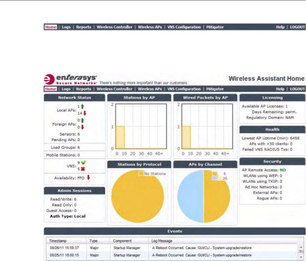
Wireless Assistant Home Screen
User Guide, V8.01 2-5
Figure 2-1 Wireless Assistant Top Menu Bar
Figure 2‐2showstheWirelessAssistantHomeScreen.Table 2‐1,describesthehomescreen
headingsanddescriptionswithlinkstosupportinformationwithintheonlinehelp.
Figure 2-2 Wireless Assistant Home Screen
DRAFT

Wireless Assistant Home Screen
2-6 Configuring the Enterasys Wireless Controller
Table 2-1 Wireless Assistant Home Screen Headings
Home Screen Heading Description
Network Status Includes real-time totals for the following components:
• Local APs - total number of active or inactive local APs. Click the number displayed to
open a separate dialog that lists the AP name, serial number, and IP address.
• Foreign APs - total number of active or inactive foreign APs. Click the number
displayed to open a separate dialog that lists the AP name, serial number, and IP
address.
• Sensors - total number of active sensors. Click the number displayed to open a
separate dialog that lists the sensor name, serial number, and IP address.
• Pending APs - total APs pending verification. Click the number displayed to open a
separate dialog that lists the AP name, serial number, and IP address.
• Load Groups - total active load groups. Click Load Groups to display the Active
Wireless Load Groups report.
• Mobile Stations - total number of active mobile stations. Click Mobile Stations to
display the All Active Client report. Within the report, Mobility Tunnels lists the total
number of mobility clients. If mobility is not enabled on the controller, then information
on Mobility Tunnels will not appear.
• VNS - total defined VNSs (enabled and disabled). Click VNS to display the total
number of enabled and disabled VNS assignments, respectively, configured on the
system.
• Availability - status of most recent session. Click Availability to display the state of
availability link (up or down) with indication if fast failover is enabled. If Availability is not
enabled on the controller, then information about Availability will not appear.
Admin Sessions Displays information on the total number of recent administrative activities including:
• Read/Write sessions - total number of currently active GUI and CLI (either SSH or
serial console ones) Read/Write sessions.
• Read-only sessions - total number of currently active GUI and CLI (either SSH or serial
console ones) Read only sessions.
• Guest Access sessions - total number of currently active GuestPortal Manager
sessions that can only be achieved through the GUI.
• Auth Type - lists the presently configured login mode.
Click each heading to access the Wireless Controller > Login Management screen. For
more information, see Configuring the Login Authentication Mode.
Stations by AP Displays a graphical representation of the total number of active stations and the number
of APs.
Click the Stations by AP heading to access the Active Clients by Wireless AP Report. For
more information, see Viewing Statistics for Wireless APs.
Stations by Protocol Displays a graphical representation of the total number of active stations grouped by
protocol.
Click the Stations by Protocol heading to access the All Active Clients Report. For more
information, see Viewing Statistics for Wireless APs.
Wired Packets by AP Displays a graphical representation of packet statistics including the total number of
packets sent and received, the total packets discarded, and the total number of unicast,
multicast, and broadcast packets.
Click the Wired Packets by AP heading to access the Wired Ethernet Statistics by
Wireless Report. For more information, see Viewing Statistics for Wireless APs.
DRAFT

Working with the Basic Installation Wizard
User Guide, V8.01 2-7
Working with the Basic Installation Wizard
TheEnterasysWirelessConvergenceSoftwaresystemprovidesabasicinstallationwizardthatcan
helpadministratorsconfiguretheminimumEnterasysWirelessControllersettingsthatare
necessarytodeployafunctioningEnterasysWirelesssolutiononanetwork.
AdministratorscanusethebasicinstallationwizardtoquicklyconfiguretheEnterasysWireless
Controllerfordeployment,andthenoncetheinstallationiscomplete,continuetorevisethe
EnterasysWirelessControllerconfigurationaccordingly.
Thebasicinstallationwizardisautomaticallylaunchedwhenanadministratorlogsontothe
EnterasysWirelessControllerforthefirsttime,includingwhenthesystemhasbeenresettothe
factorydefaultsettings.Inaddition,thebasicinstallationwizardcanalsobelaunchedatanytime
fromtheleftpaneoftheEnterasysWirelessControllerConfigurationscreen.
APs by Channel Displays a graphical representation of the total number of active APs grouped by channel.
Click the APs by Channel heading to access the Active Wireless APs Report. For more
information, see Viewing Statistics for Wireless APs.
Licensing Displays licensing information including:
• Available AP Licenses - total number of available licenses.
• Days Remaining - number of days remaining on this license key.
• Regulatory Domain - Domain information for this license period.
Click the Licensing heading to access the Wireless Controller > Software Maintenance
screen. For more information, see Installing the License Keys.
Health Displays network health statistics including:
• Local AP Uptime (min)
• APs with > 30 clients
• Failed VNS RADIUS Txs
Click each heading to access the Active Wireless APs Report. For more information, see
Viewing Statistics for Wireless APs.
Security Displays totals for the following security related statistics:
• AP remote access - click to access the Wireless APs > AP Registration page
• WLANs using WEP
• WLANs using TKIP
• Ad Hoc Networks - click to access the Mitigator > Rogue Detection page
• External APs - click to access the Mitigator > Rogue Detection page
• Rogue APs - click to access the Mitigator > Rogue Detection page
For more information, see Defining Properties for the Discovery Process, and Working
with Mitigator Scan Results.
Events Displays major events that impact network performance and efficiency. Each event listed
includes a timestamp of the event, the type or classification of the event, which
component is impacted by the event, and a log message providing specific information for
the event.
Click the Events heading to access the Logs > Logs & Traces page. For more
information, see Available Reports and Displays.
Table 2-1 Wireless Assistant Home Screen Headings (continued)
Home Screen Heading Description
DRAFT
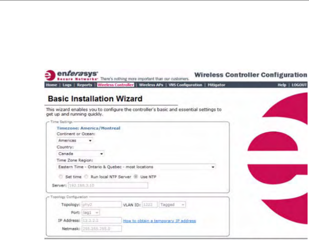
Working with the Basic Installation Wizard
2-8 Configuring the Enterasys Wireless Controller
To Configure the Enterasys Wireless Controller with the Basic Installation Wizard:
1. LogontotheEnterasysWirelessController.Formoreinformation,see“Loggingontothe
EnterasysWirelessController”onpage 2‐4.
2. Fromthetopmenu,clickWirelessController.TheWirelessControllerConfigurationscreen
isdisplayed.
3. Intheleftpane,clickInstallationWizard.TheBasicInstallationWizardscreenisdisplayed.
4. IntheTimeSettingssection,configuretheEnterasysWirelessControllertimezone:
–ContinentorOcean—Clicktheappropriatelarge‐scalegeographicgroupingforthetime
zone.
–Country—Clicktheappropriatecountryforthetimezone.Thecontentsofthedrop‐
downlistchange,basedontheselectionintheContinentorOceandrop‐downlist.
–TimeZoneRegion—Clicktheappropriatetimezoneregionfortheselectedcountry.
5. ToconfiguretheEnterasysWirelessController’stime,dooneofthefollowing:
–TomanuallysettheEnterasysWirelessControllertime,usetheYear,Month,Day,HR,
andMin.drop‐downliststospecifythetime.
–TousetheEnterasysWirelessControllerastheNTPtimeserver,selecttheRunlocalNTP
Serveroption.
–TouseNTPtosettheEnterasysWirelessControllertime,selecttheUseNTPoption,and
thentypetheIPaddressofanNTPtimeserverthatisaccessibleontheenterprise
network.
TheNetworkTimeProtocolisaprotocolforsynchronizingtheclocksofcomputersystems
overpacket‐switcheddatanetworks.
6. IntheTopologyConfigurationsection,clickthephysicalinterfaceoftheEnterasysWireless
Controlleryouwanttoassignasadataport.ThesystemassignsdefaultIPAddressand
DRAFT
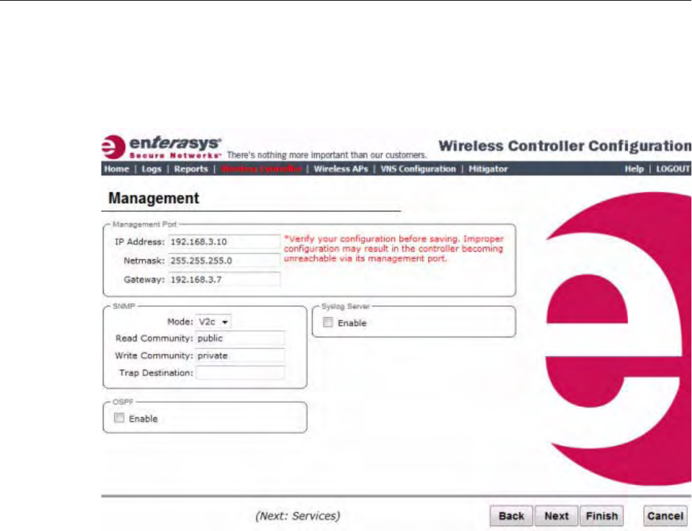
Working with the Basic Installation Wizard
User Guide, V8.01 2-9
Netmaskvaluesforthedataport.Ifapplicable,typeadifferentIPaddressandnetmaskfor
theselectedphysicalinterface.
ForinformationonhowtoobtainatemporaryIPaddressfromthenetwork,clickHowto
obtainatemporaryIPaddress.
7. ClickNext.TheManagementscreenisdisplayed.
8. IntheManagementPortsection,confirmtheportconfigurationvaluesthatweredefined
whentheEnterasysWirelessControllerwasphysicallydeployedonthenetwork.If
applicable,editthesevalues:
–IPAddress—DisplaystheIPaddressfortheEnterasysWirelessController’s
managementport.Revisethisasappropriatefortheenterprisenetwork.
–Netmask—DisplaystheappropriatesubnetmaskfortheIPaddresstoseparatethe
networkportionfromthehostportionoftheaddress.
–Gateway—Displaysthedefaultgatewayofthenetwork.
9. IntheSNMPsection,clickV2corV3intheModedrop‐downlisttoenableSNMP,if
applicable.Onlyonemodecanbesupportedonthecontrolleratatime.
IfyouselectedV2c,dothefollowing:
–ReadCommunity—Typethepasswordthatisusedforread‐onlySNMP
communication.
–WriteCommunity—TypethepasswordthatisusedforwriteSNMPcommunication.
–TrapDestination—TypetheIPaddressoftheserverusedasthenetworkmanagerthat
willreceiveSNMPmessages.
10. IntheOSPFsection,selecttheEnablecheckboxtoenableOSPF,ifapplicable.UseOSPFto
allowtheEnterasysWirelessControllertoparticipateindynamicrouteselection.OSPFisa
DRAFT
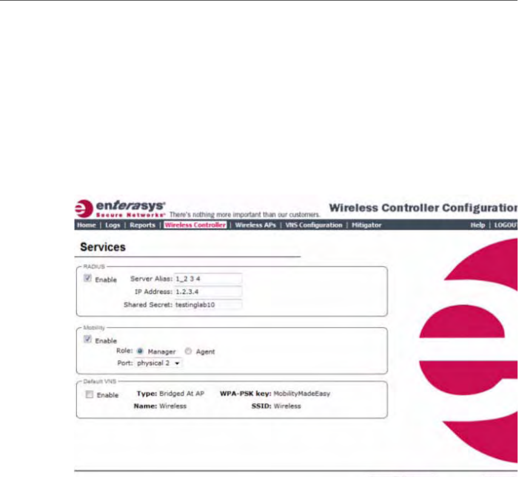
Working with the Basic Installation Wizard
2-10 Configuring the Enterasys Wireless Controller
protocoldesignedformediumandlargeIPnetworkswiththeabilitytosegmentroutesinto
differentareasbyroutinginformationsummarizationandpropagation.
Dothefollowing:
–Port—ClickthephysicalinterfaceoftheEnterasysWirelessControlleryouwantto
assignasarouterport.
–AreaID—Typethedesiredarea.Area0.0.0.0isthemainareainOSPF.
11. IntheSyslogServersection,selecttheEnablecheckboxtoenablethesyslogprotocolforthe
EnterasysWirelessController,ifapplicable.Syslogisaprotocolusedforthetransmissionof
eventnotificationmessagesacrossnetworks.
IntheIPAddressbox,typetheIPaddressofthesyslogserver.
12. ClickNext.TheServicesscreenisdisplayed.
13. IntheRADIUSsection,selecttheEnablecheckboxtoenableRADIUSloginauthentication,if
applicable.RADIUSloginauthenticationusesaRADIUSservertoauthenticateuserlogin
attempts.RADIUSisaclient/serverauthenticationandauthorizationaccessprotocolusedby
anetworkaccessserver(NAS)toauthenticateusersattemptingtoconnecttoanetwork
device.
Dothefollowing:
–ServerAlias—TypeanamethatyouwanttoassigntotheRADIUSserver.Youcantype
anameorIPaddressoftheserver.
–Hostname/IP—TypetheRADIUSserver’shostnameorIPaddress.
–SharedSecret—Typethepasswordthatwillbeusedtovalidatetheconnectionbetween
theEnterasysWirelessControllerandtheRADIUSserver.
14. IntheMobilitysection,selecttheEnablecheckboxtoenabletheEnterasysWireless
Controllermobilityfeature,ifapplicable.Mobilityallowsawirelessdeviceusertoroam
seamlesslybetweendifferentWirelessAPsonthesameordifferentEnterasysWireless
Controllers.
DRAFT

Working with the Basic Installation Wizard
User Guide, V8.01 2-11
AdialogisdisplayedinformingyouthatNTPisrequiredforthemobilityfeatureand
promptingyoutoconfirmyouwanttoenablemobility.
ClickOKtocontinue,andthendothefollowing:
Role—SelecttherolefortheEnterasysWirelessController,ManagerorAgent.One
EnterasysWirelessControlleronthenetworkisdesignatedasthemobilitymanagerandall
otherEnterasysWirelessControllersaredesignatedasmobilityagents.
Port—ClicktheinterfaceontheEnterasysWirelessControllertobeusedforcommunication
betweenmobilitymanagerandmobilityagent.Ensurethattheselectedinterfaceisroutable
onthenetwork.Formoreinformation,seeChapter 12,ConfiguringMobility.
ManagerIP—TypetheIPaddressofthemobilitymanagerportiftheEnterasysWireless
Controllerisconfiguredasthemobilityagent.
15. IntheDefaultVNSsection,selecttheEnablecheckboxtoenableadefaultVNSforthe
EnterasysWirelessController.ThedefaultVNSparametersaredisplayed.Referto“Virtual
NetworkServices”onpage 1‐11formoreinformationaboutthedefaultVNS.
16. ClickFinish.TheSuccessscreenisdisplayed.Enterasysrecommendsthatyouchangethe
factorydefaultadministratorpassword.Dothefollowing:
–NewPassword—Typeanewadministratorpassword.
–ConfirmPassword—Typethenewadministratorpasswordagain.
17. ClickSave.Yournewpasswordissaved.
18. ClickOK,andthenclickClose.TheEnterasysWirelessAssistanthomescreenisdisplayed.
Note: If the Enterasys Wireless Controller is configured as a mobility agent, it will act as an NTP
client and use the mobility manager as the NTP server. If the Enterasys Wireless Controller is
configured as a mobility manager, the Enterasys Wireless Controller’s local NTP will be enabled for
the mobility domain.
DRAFT
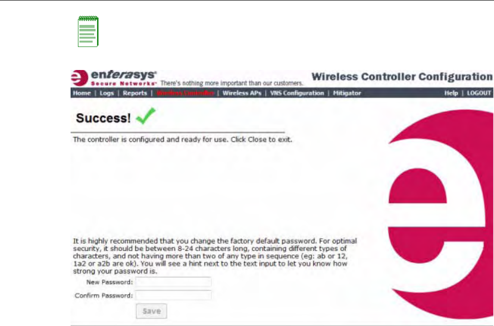
Configuring the Enterasys Wireless Controller for the First Time
2-12 Configuring the Enterasys Wireless Controller
Configuring the Enterasys Wireless Controller for the First Time
AssoonastheEnterasysWirelessControllerisdeployed,youshouldperformaseriesof
configurationtasks.Thesetasksinclude:
•ChangingtheAdministratorPassword
•ApplyingProductLicenseKeys
•SettingUptheDataPorts
•SettingUpInternalVLANIDandMulticastSupport
•SettingUpStaticRoutes
•SettingUpOSPFRouting
•ConfiguringFilteringattheInterfaceLevel
•ProtectingtheController’sInterfacesandInternalCaptivePortalPage
•ConfiguringtheLoginAuthenticationMode
•ConfiguringSNMP
•ConfiguringNetworkTime
•ConfiguringDNSServersforResolvingHostNamesofNTPandRADIUSServers
AlthoughthebasicinstallationwizardhasalreadyconfiguredsomeaspectsoftheEnterasys
WirelessControllerdeployment,youcancontinuetorevisetheEnterasysWirelessController
configurationaccordingtoyournetworkneeds.
Note: The Enterasys Wireless Controller reboots after you click Save if the time zone is changed
during the Basic Install Wizard. If the IP address of the management port is changed during the
configuration with the Basic Install Wizard, the Enterasys Wireless Assistant session is terminated
and you will need to log back in with the new IP address.
DRAFT

Configuring the Enterasys Wireless Controller for the First Time
User Guide, V8.01 2-13
Changing the Administrator Password
Enterasysrecommendsthatyouchangeyourdefaultadministratorpasswordonceyoursystemis
deployed.TheEnterasysWirelessControllerdefaultpasswordisabc123.WhentheEnterasys
WirelessControllerisinstalledandyouelecttochangethedefaultpassword,thenewpassword
mustbeaminimumofeightcharacters.
Theminimumeightcharacterpasswordlengthisnotappliedtoexistingpasswords.Forexample,
ifasixcharacterpasswordisalreadybeingusedandanupgradeofthesoftwareisperformed,the
softwaredoesnotrequirethepasswordtobechangedtoaminimumofeightcharacters.However,
oncetheupgradeiscompletedandanewaccountiscreated,orthepasswordofanexisting
accountischanged,thenewpasswordlengthminimumwillbeenforced.
To Change the Administrator Password:
1. Fromthetopmenu,clickWirelessController.TheWirelessControllerConfigurationscreen
isdisplayed.
2. Intheleftpane,clickLoginManagement.
3. IntheFullAdministratortable,clicktheadministratorusername.
4. InthePasswordbox,typethenewadministratorpassword.
5. IntheConfirmPasswordbox,typethenewadministratorpasswordagain.
6. ClickChangePassword.
Applying Product License Keys
TheEnterasysWirelessController’slicensesystemworksonsimplesoftware‐basedkeystrings.A
keystringconsistsofaseriesofnumbersand/orletters.Usingthesekeystrings,youcanlicense
thesoftware,andenhancethecapacityoftheEnterasysWirelessControllertomanageadditional
WirelessAPs.
Thekeystringscanbeclassifiedintothefollowingvariants:
•ActivationKey—Activatesthesoftware.Thiskeyisfurtherclassifiedintotwosub‐variants:
–TemporaryActivationKey—Activatesthesoftwareforatrialperiodof90days.
–PermanentActivationKey—Activatesthesoftwareforaninfiniteperiod.
•OptionKey—Activatestheoptionalfeature:
–CapacityEnhancementKey—EnhancesthecapacityoftheEnterasysWireless
ControllertomanageadditionalWirelessAPs.Youmayhavetoaddmultiplecapacity
enhancementkeystoreachtheEnterasysWirelessController’slimit.Dependingonthe
EnterasysWirelessControllermodel,acapacityenhancementkeyaddsthefollowing
WirelessAPs:
‐C5110—Adds25WirelessAPs
‐C4110—Adds25WirelessAPs
‐C20—Adds16WirelessAPs
‐C25—Adds16WirelessAPs
Note: The Enterasys Wireless Controller provides you with local login authentication mode, the
RADIUS-based login authentication mode, and combinations of the two authentication modes. The
local login authentication is enabled by default. For more information, see “Configuring the Login
Authentication Mode” on page 2-35.
DRAFT

Configuring the Enterasys Wireless Controller for the First Time
2-14 Configuring the Enterasys Wireless Controller
‐V2110—Adds16WirelessAPs
TheEnterasysWirelessControllercanbeinthefollowinglicensingmodes:
•Unlicensed—WhentheEnterasysWirelessControllerisnotlicensed,itoperatesin‘demo
mode.’In‘demomode,’theEnterasysWirelessControllerallowsyoutooperateasmany
WirelessAPsasyouwant,subjecttothemaximumlimitoftheplatformtype.Indemomode,
youcanuseonlytheb/gradio,withchannels6,11,andauto.11nsupportandMobilityare
disabledindemomode.
•Licensedwithatemporaryactivationkey—Atemporaryactivationkeycomeswitha
regulatorydomain.Withthetemporaryactivationkey,youcanselectacountryfromthe
domainandoperatetheWirelessAPsonanychannelpermittedbythecountry.Atemporary
activationkeyallowsyoutouseallsoftwarefeatures.YoucanoperateasmanyWirelessAPs
asyouwant,subjecttothemaximumlimitoftheplatformtype.
Atemporaryactivationkeyisvalidfor90days.Oncethe90daysareup,thetemporarykey
expires.YoumustgetapermanentactivationkeyandinstallitontheEnterasysWireless
Controller.Ifyoudonotinstallapermanentactivationkey,theEnterasysWirelessController
willstartgeneratingeventlogsevery15minutes,indicatingthatanappropriatelicenseis
requiredforthecurrentsoftwareversion.Inaddition,youwillnotbeabletoedittheVirtual
NetworkServices(VNS)parameters.
•Licensedwithpermanentactivationkey—Apermanentactivationkeyisvalidforan
infiniteperiod.Inaddition,unlikethetemporaryactivationkey,thepermanentactivationkey
allowsyoutooperateastipulatednumberoftheWirelessAPs,dependingupontheplatform
type.IfyouwanttoconnectadditionalWirelessAPs,youhavetoinstallacapacity
enhancementkey.Youmayevenhavetoinstallmultiplecapacityenhancementkeystoreach
theEnterasysWirelessController’slimit.
ThefollowingtableliststheplatformtypeandthecorrespondingnumberoftheWirelessAPs
allowedbythepermanentactivationkey.
IftheEnterasysWirelessControllerdetectsmultiplelicenseviolations,suchascapacity
enhancement,agraceperiodcounterwillstartfromthemomentthefirstviolationoccurred.The
EnterasysWirelessControllerwillgenerateeventlogsforeveryviolation.Theonlywaytoleave
thegraceperiodistoclearalloutstandinglicenseviolations.
Note: If you connect additional Wireless APs to a Enterasys Wireless Controller that has a
permanent activation key without installing a capacity enhancement key, a grace period of seven
days will start. You must install the correct key during the grace period. If you do not install the key,
the Enterasys Wireless Controller will start generating event logs every 15 minutes, indicating that
the key is required. In addition, you will not be able to edit the Virtual Network Services (VNS)
parameters.
Table 2-2 Platform Type / Wireless APs Allowed by Permanent Activation Key
Platform Wireless APs permitted by
permanent activation key Platform’s optimum
limit
Number of capacity
enhancement keys to reach
the optimum limit
C20 16 32 1
C25 16 48 2
C4110 50 250 8
C5110 150 525 15
V2110 8 120 7
DRAFT
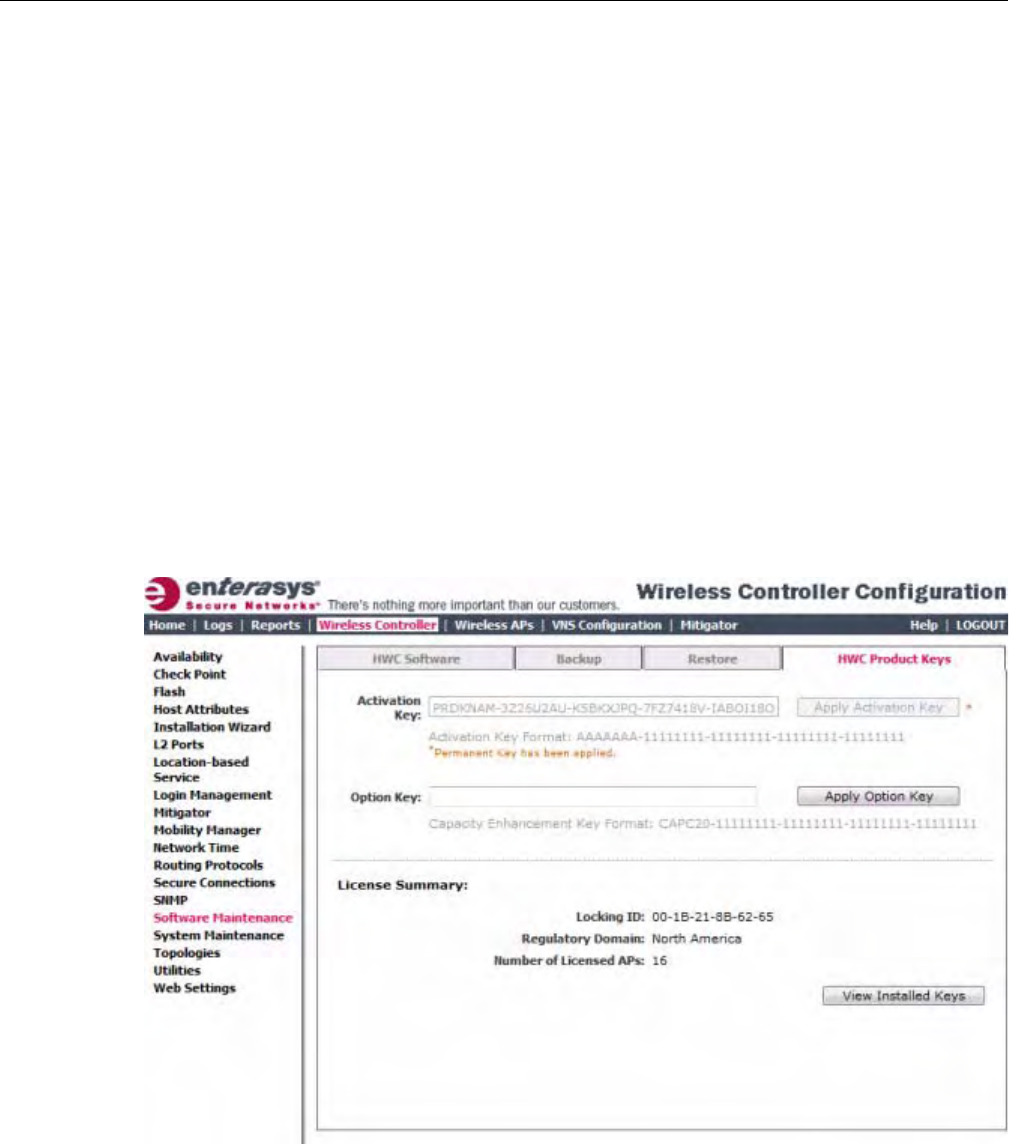
Configuring the Enterasys Wireless Controller for the First Time
User Guide, V8.01 2-15
TheEnterasysWirelessControllercanbeinanunlicensedstateforaninfiniteperiod.However,if
youinstallatemporaryactivationkey,theunlicensedstateisterminated.Afterthevalidityofa
temporaryactivationkeyandtherelatedgraceperiodexpire,theEnterasysWirelessController
willgenerateeventlogsevery15minutes,indicatingthatanappropriatelicenseisrequiredforthe
currentsoftwareversion.Inaddition,youwillnotbeabletoedittheVirtualNetworkServices
(VNS)parameters.
Installing the License Keys
ThissectiondescribeshowtoinstallthelicensekeyontheEnterasysWirelessController.Itdoes
notexplainhowtogeneratethelicensekey.Forinformationonhowtogeneratethelicensekey,
seetheEnterasysWirelessLicenseCertificate,whichissenttoyouviatraditionalmail.
YouhavetotypethelicensekeysontheEnterasysWirelessAssistantGUI.
To Install the License Keys:
1. Fromthetopmenu,clickWirelessController.TheWirelessControllerConfigurationscreen
isdisplayed.
2. Intheleftpane,clickSoftwareMaintenance.
3. ClicktheHWCProductKeystab.
Thebottompanedisplaysthelicensesummary.
4. Ifyouareinstallingatemporaryorpermanentactivationlicensekey,typethekeyinthe
ActivationKeybox,andthenclicktheApplyActivationKeybutton.
5. Ifyouareinstallingacapacityenhancement,typethekeyintheOptionKeybox,andthen
clicktheApplyOptionKeybutton.
6. Toviewinstalledkeys,clickViewInstalledKeys.
DRAFT
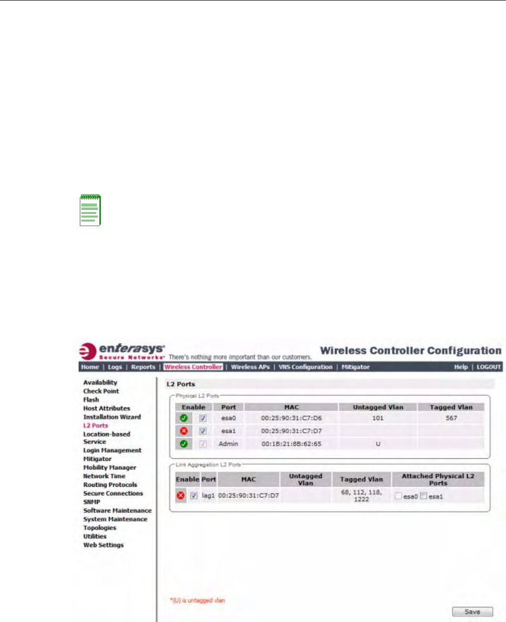
Configuring the Enterasys Wireless Controller for the First Time
2-16 Configuring the Enterasys Wireless Controller
Setting Up the Data Ports
AnewEnterasysWirelessControllerisshippedfromthefactorywithallitsdataportssetup.
Supportofmanagementtrafficisdisabledonalldataports.Bydefault,datainterfacestatesare
enabled.Adisabledinterfacedoesnotallowdatatoflow(receive/transmit).
PhysicalportsarerepresentedbytheL2(Ethernet)Ports.TheL2portcanbeaccessedfromL2
PortstabsunderEnterasysWirelessControllerConfiguration.TheL2Portscannotberemoved
fromthesystembuttheiroperationalstatuscanbechanged.RefertoViewingandChangingthe
L2PortsInformation.
LinkAggregationportsarerepresentedbytheL2(peer‐to‐peer)LAGPorts.TheL2portand
TopologyinformationcanbeaccessedfromL2PortsandTopologytabsunderEnterasysWireless
ControllerConfiguration.TheLAGL2Portscannotberemovedfromthesystembuttheir
operationalstatuscanbechanged.RefertoViewingandChangingtheL2PortsInformation.
Viewing and Changing the L2 Ports Information
To View and Change the L2 Port Information:
1. Fromthetopmenu,clickWirelessController.TheWirelessControllerConfigurationscreen
isdisplayed.
2. Intheleftpane,clickL2Ports.TheL2Portstabisdisplayed.
Note: You can redefine a data port to function as a Third-Party AP Port. Refer to Viewing and
Changing the Physical Topologies for more information.
DRAFT

Configuring the Enterasys Wireless Controller for the First Time
User Guide, V8.01 2-17
TheL2PortstabpresentsthePhysical(thatis,Ethernet)andLinkAggregationLAG(peerto
peer)dataportsthatexistontheEnterasysWirelessController.Theseportscannotbedeleted
andnewonescannotbecreated.
LAGportsarestaticallyconfiguredbyadding/removingphysicalportsfromtheLAG.
PhysicalportbelongtoatmostoneLAGatonetime.L2portattachedtoaLAGportdoesnot
haveanypropertiesandcouldnotbeattachedtoanytopology.TheL2portsattachedtoLAG
portscanbeenabledordisabled.Optional,ifchangesoccurtotheportphysicalparameters
(speed,halforfullduplex),awarningwillbedisplayedtoindicatethattheL2portdoesnot
meetLAGconditions.
Considerationsforattaching/detachingregularL2portstoLAGports:
•RegularL2portshouldnothaveanybridgedandphysicaltopologiesassociatedwiththe
port.
•RegularL2portshouldnotbedisabled.
•L2portscanbedetachedfromLAGportsregardlessofanytopologiesattachedtothe
LAGport.
•IftheL2portisthelastremaininginLAG,awarningwillbeissued.IflastportoftheLAG
hasbeendetached,theLAGshouldbeinoperationalDOWNstate.
•AfterdetachingtheL2port,itcouldbeattachedtoanybridgedorphysicaltopologyor
pointsviaaroutingtabletotheportanyroutedtopology.
AssigninganybridgedorphysicaltopologywithoutspecifyinganL2portisnotsupported.
However,youcanmoveanybridgedandphysicaltopologytoeitheraphysicalorLAGL2
port.
Physical:
–C5110—Threedataports,displayedasesa0,esa1,andesa2.
– C4110—Fourdataports,displayedasPort1,Port2,Port3,andPort4.
–C20—Twodataports,displayedasesa0andesa1.
–C25—Twodataports,displayedasesa0andesa1.
– V2110—Twodataports,displayedasesa0andesa1.
LinkAggregation:
– C5110—Onedataport,displayedaslag1
– C4110—Onedataport,displayedaslag1.
–C20—Onedataport,displayedlag1.
–C25—Onedataport,displayedaslag1.
Alsoan“A d m i n ” portiscreatedbydefault.Thisrepresentsaphysicalport,separatefromthe
otherdataports,beingusedformanagementconnectivity.
ParametersdisplayedfortheL2Portsare:
–Operationalstatus,representedgraphicallywithagreencheckmark(UP)orredX
(DOWN).Thisistheonlyconfigurableparameter.
–Portname,asdescribedabove.
–MACaddress,asperEthernetstandard.
– UntaggedVLAN,displaystheassociateduntaggedVLANID.ThisIDisuniqueamong
topologies.
–TaggedVLAN,displaystheassociatedtaggedVLANID.
DRAFT
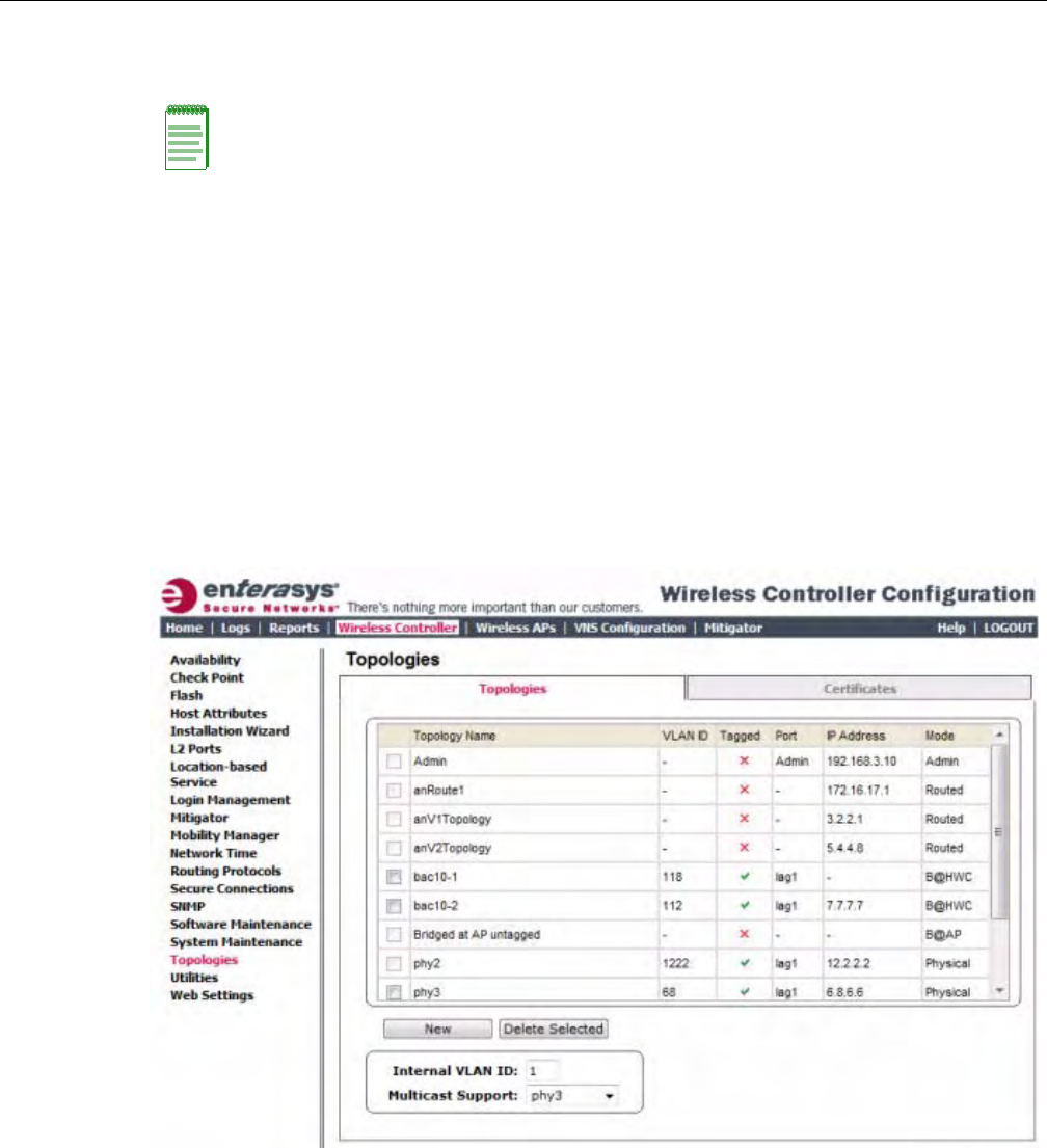
Configuring the Enterasys Wireless Controller for the First Time
2-18 Configuring the Enterasys Wireless Controller
– AttachedPhysicalL2Ports(LinkAggregationL2Portsonly)selectthephysicalL2ports
associatedwiththelinkaggregationL2Ports.
3. Ifdesired,changetheoperationalstatusbyclickingtheEnablecheckbox.
Youcanchangetheoperationalstateforeachport.Bydefault,datainterfacestatesare
enabled.Iftheyarenotenabled,youcanenablethemindividually.Adisabledinterfacedoes
notallowdatatoflow(receive/transmit).
Viewing and Changing the Physical Topologies
To View and Change the L2 Port Topologies:
1. Fromthetopmenu,clickWirelessController.TheWirelessControllerConfigurationscreen
isdisplayed.
2. Intheleftpane,clickTopologies.TheTopologiestabisdisplayed.
AnassociatedtopologyentryiscreatedbydefaultforeachL2Portwiththesamename.
Note: Refer to Viewing and Changing the Physical Topologies for more information about L2 port
topologies.
DRAFT
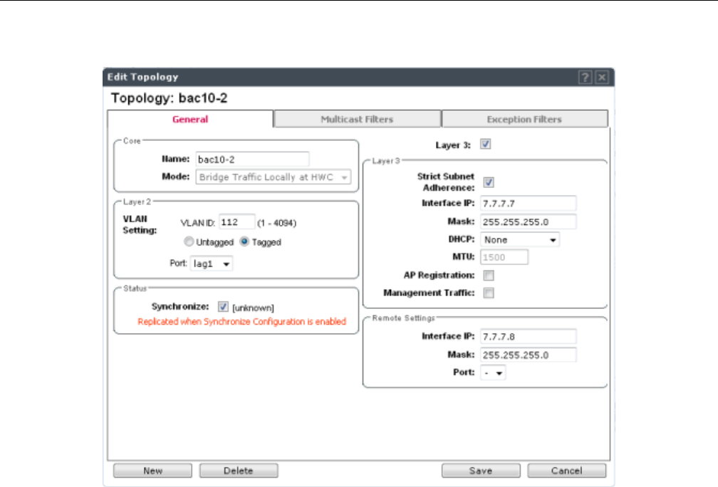
Configuring the Enterasys Wireless Controller for the First Time
User Guide, V8.01 2-19
3. Tochangeanyoftheassociatedparameters,clickonthetopologyentrytobemodified.An
“EditTopology”popupwindowappears.
Forthedataportspredefinedinthesystem,NameandModearenotconfigurable.
4. Optionally,configureoneofthephysicaltopologiesforThirdPartyAPconnectivityby
clickingthe3rdPartyAPTopologycheckbox.
Youmustconfigureatopologytowhichyouwillbeconnectingthird‐partyAPsbychecking
thisbox.Onlyonetopologycanbeconfiguredforthird‐partyAPs.
Third‐partyAPsmustbedeployedwithinasegregatednetworkforwhichtheEnterasys
WirelessControllerbecomesthesinglepointofaccess(i.e.,routinggateway).Whenyou
defineathird‐partyAPtopology,theinterfacesegregatesthethird‐partyAPfromthe
remainingnetwork.
5. ToconfigureaninterfaceforVLANassignment,configuretheVLANSettingsintheLayer2
box.
WhenyouconfigureaEnterasysWirelessControllerporttobeamemberofaVLAN,you
mustensurethattheVLANconfiguration(VLANID,taggedoruntaggedattribute,andPort
ID)ismatchedwiththecorrectconfigurationonthenetworkswitch.
6. Toreplicatetopologysettings,clickSynchronizeintheStatusbox.
7. IfthedesiredIPconfigurationisdifferentfromtheonedisplayed,changetheInterfaceIPand
MaskaccordinglyintheLayer3box.
Forthistypeofdatainterface,theLayer3checkboxisselectedautomatically.Thisallowsfor
IPInterfaceandsubnetconfigurationtogetherwithothernetworkingservices.
8. TheMTUvaluespecifiestheMaximumTransmissionUnitormaximumpacketsizeforthis
topology.Thefixedvalueis1500bytesforphysicaltopologies.
IfyouareusingOSPF,besurethattheMTUofalltheinterfacesintheOSPFlinkmatch.
DRAFT
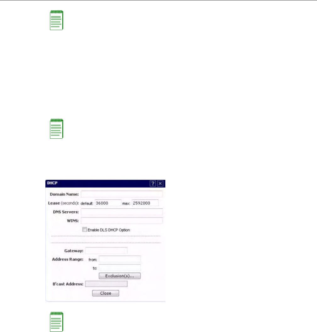
Configuring the Enterasys Wireless Controller for the First Time
2-20 Configuring the Enterasys Wireless Controller
9. ToenableAPregistrationthroughthisinterface,selecttheAPRegistrationcheckbox.
WirelessAPsusethisportfordiscoveryandregistration.Othercontrollerscanusethisportto
enableinter‐controllerdevicemobilityifthisportisconfiguredtouseSLPortheEnterasys
WirelessControllerisrunningasamanagerandSLPisthediscoveryprotocolusedbythe
agents.
10. Toenablemanagementtraffic,selecttheManagementTrafficcheckbox.Enabling
managementprovidesaccesstoSNMP(v2,V3,get),SSH,andHTTPsmanagementinterfaces.
11. ToenablethelocalDHCPServerontheEnterasysWirelessController,intheDHCPbox,
selectLocalServer.Then,clickontheConfigurebuttontoopentheDHCPconfigurationpop
upwindow.
a. IntheDomainNamebox,typethenameofthedomainthatyouwanttheWirelessAPsto
useforDNSServer’sdiscovery.
b. IntheLease(seconds)defaultbox,typethetimeperiodforwhichtheIPaddresswillbe
allocatedtotheWirelessAPs(oranyotherdevicerequestingit).
c. IntheLease(seconds)maxbox,typethemaximumtimeperiodinsecondsforwhichthe
IPaddresswillbeallocatedtotheWirelessAPs.
d. IntheDNSServersbox,typetheDNSServer’sIPaddressifyouhaveaDNSServer.
e. IntheWINSbox,typetheWINSServer’sIPaddressifyouhaveaWINSServer.
Note: If the routed connection to an AP traverses a link that imposes a lower MTU than the default
1500 bytes, the Enterasys Wireless Controller and AP participate in automatic MTU discovery and
adjust their settings accordingly.At the Enterasys Wireless Controller, MTU adjustments are tracked
on a per AP basis. If the Enterasys Wireless software cannot discover the MTU size, it enforces the
static MTU size.
Note: This option does not override the built-in protection filters on the port.
The built-in protection filters for the port, which are restrictive in the types of packets that are
allowed to reach the management plane, are extended with a set of definitions that allow for access
to system management services through that interface (SSH, SNMP, HTTPS:5825).
Note: The local DHCP Server is useful as a general-purpose DHCP Server for small subnets.
DRAFT
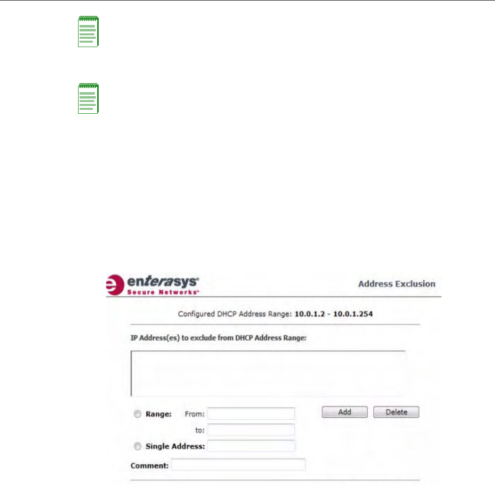
Configuring the Enterasys Wireless Controller for the First Time
User Guide, V8.01 2-21
f. IntheGatewaybox,typetheIPaddressofthedefaultgateway.
g. ConfiguretheaddressrangefromwhichthelocalDHCPServerwillallocateIPaddresses
totheWirelessAPs.
‐IntheAddressRange:frombox,typethestartingIPaddressoftheIPaddressrange.
‐IntheAddressRange:tobox,typetheendingIPaddressoftheIPaddressrange.
h. ClicktheExclusion(s)buttontoexcludeIPaddressesfromallocationbytheDHCPServer.
TheDHCPAddressExclusionwindowopens.
TheEnterasysWirelessControllerautomaticallyaddstheIPaddressesoftheInterfaces
(Ports),andthedefaultgatewaytotheexclusionlist.YoucannotremovetheseIP
addressesfromtheexclusionlist.
‐SelecttheRangeradiobutton.IntheFrombox,typethestartingIPaddressoftheIP
addressrangethatyouwanttoexcludefromtheDHCPallocation.
‐IntheTobox,typetheendingIPaddressoftheIPaddressrangethatyouwantto
excludefromtheDHCPallocation.
‐Toexcludeasingleaddress,selecttheSingleAddressradiobuttonandtypetheIP
addressintheadjacentbox.
‐IntheCommentbox,typeanyrelevantcomment.Forexample,youcantypethe
reasonforwhichacertainIPaddressisexcludedfromtheDHCPallocation.
‐ClickonAdd.TheexcludedIPaddressesaredisplayedintheIPAddress(es)to
excludefromDHCPAddressRangebox.
‐TodeleteaIPAddressfromtheexclusionlist,selectitintheIPAddress(es)to
excludefromDHCPRangebox,andthenclickDelete.
Note: You can type multiple entries in the DNS Servers and WINS boxes. Each entry must be
separate by a comma. These two fields are not mandatory to enable the local DHCP feature.
Note: Since the Enterasys Wireless Controller is not allowed to be the gateway for the segment,
including Wireless APs, you cannot use the Interface IP address as the gateway address for
physical and Bridged at Controller topology. For routed topology, the controller IP address must be
the gateway.
DRAFT
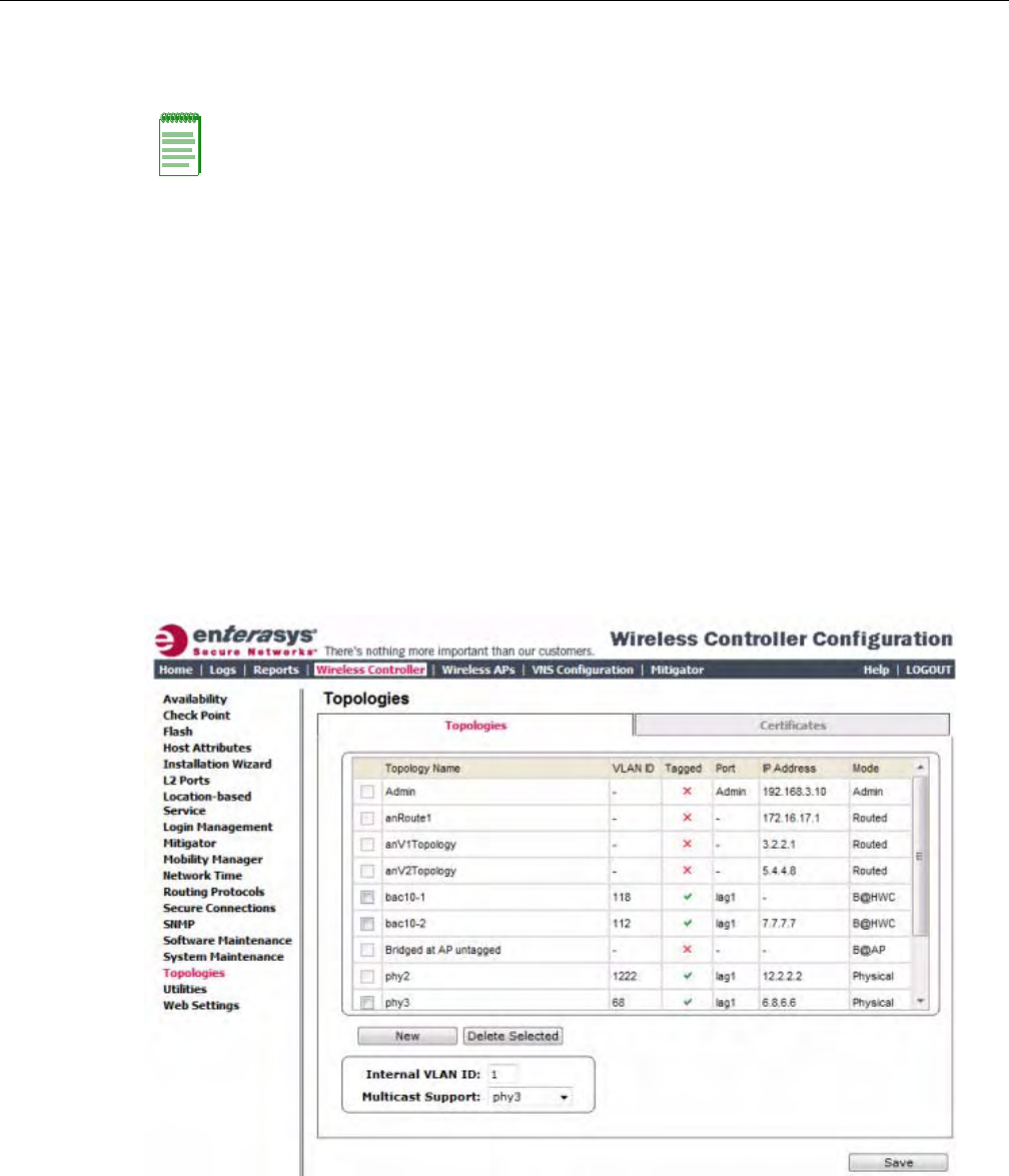
Configuring the Enterasys Wireless Controller for the First Time
2-22 Configuring the Enterasys Wireless Controller
‐Tosaveyourchanges,clickOK.
i. ClickClosetoclosetheDHCPconfigurationwindow.
12. YouarereturnedtotheL2porttopologyeditwindow.
Setting Up Internal VLAN ID and Multicast Support
YoucanconfiguretheInternalVLANID,andenablemulticastsupport.TheinternalVLANused
onlyinternallyandisnotvisibleontheexternaltraffic.Thephysicaltopologyusedformulticastis
representedbyaphysicaltopologyto/fromwhichthemulticasttrafficisforwardedinconjunction
withthevirtualroutedtopologies(andVNSs)configuredonthecontroller.Pleasenotethatno
multicastroutingisavailableatthistime.
ToconfiguretheInternalVLANIDandenablemulticastsupport:
1. Fromthetopmenu,clickWirelessController.TheWirelessControllerConfigurationscreen
isdisplayed.
2. Intheleftpane,clickTopologies.TheTopologiestabisdisplayed.
3. ClicktheInterfacestab.
4. IntheInternalVLANIDbox,typetheinternalVLANID.
5. FromtheMulticastSupportdrop‐downlist,selectthedesiredphysicaltopology.
6. Tosaveyourchanges,clickSave.
Note: The Broadcast (B’cast) Address field is view only. This field is computed from the mask and
the IP addresses.
DRAFT
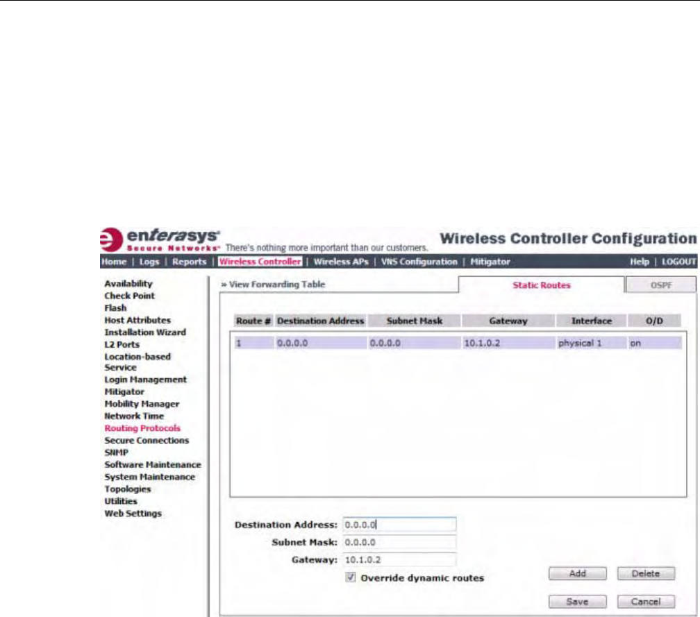
Configuring the Enterasys Wireless Controller for the First Time
User Guide, V8.01 2-23
Setting Up Static Routes
WhensettingupaEnterasysWirelessControllerroutingprotocol,youmustdefineadefaultroute
toyourenterprisenetwork,eitherwithastaticrouteorbyusingtheOSPFprotocol.Adefault
routeenablestheEnterasysWirelessControllertoforwardpacketstodestinationsthatdonot
matchamorespecificroutedefinition.
To Set a Static Route on the Enterasys Wireless Controller:
1. Fromthetopmenu,clickWirelessController.TheWirelessControllerConfigurationscreen
isdisplayed.
2. Intheleftpane,clickRoutingProtocols.TheStaticRoutestabisdisplayed.
3. Toaddanewroute,intheDestinationAddressboxtypethedestinationIPaddressofa
packet.
Todefineadefaultstaticrouteforanyunknownaddressnotintheroutingtable,type0.0.0.0.
4. IntheSubnetMaskbox,typetheappropriatesubnetmasktoseparatethenetworkportion
fromthehostportionoftheIPaddress(typically255.255.255.0).Todefinethedefaultstatic
routeforanyunknownaddress,type0.0.0.0.
5. IntheGatewaybox,typetheIPaddressoftheadjacentrouterportorgatewayonthesame
subnetastheEnterasysWirelessControllertowhichtoforwardthesepackets.ThisistheIP
addressofthenexthopbetweentheEnterasysWirelessControllerandthepacket’sultimate
destination.
6. ClickAdd.Thenewrouteisaddedtothelistofroutes.
7. SelecttheOverridedynamicroutescheckboxtogivepriorityovertheOSPFlearnedroutes,
includingthedefaultroute,whichtheEnterasysWirelessControllerusesforrouting.This
optionisenabledbydefault.
Toremovethispriorityforstaticroutes,sothatroutingiscontrolleddynamicallyatalltimes,
cleartheOverridedynamicroutescheckbox.
DRAFT
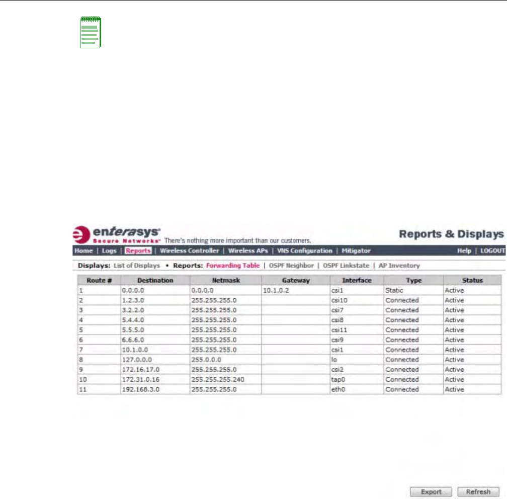
Configuring the Enterasys Wireless Controller for the First Time
2-24 Configuring the Enterasys Wireless Controller
8. Tosaveyourchanges,clickSave.
Viewing the Forwarding Table
Youcanviewthedefinedroutes,whetherstaticorOSPF,andtheircurrentstatusinthe
forwardingtable.
To View the Forwarding Table on the Enterasys Wireless Controller:
1. FromtheRoutingProtocolsStaticRoutestab,clickViewForwardingTable.TheForwarding
Tableisdisplayed.
2. Alternatively,fromthetopmenu,clickReports.TheReports&Displaysscreenisdisplayed.
Then,clickForwardingTable.TheForwardingTableisdisplayed.
Thisreportdisplaysalldefinedroutes,whetherstaticorOSPF,andtheircurrentstatus.
3. Toupdatethedisplay,clickRefresh.
Setting Up OSPF Routing
ToenableOSPF(OSPFRFC2328)routing,youmust:
•SpecifyatleastonetopologyonwhichOSPFisenabledonthePortSettingsoptionofthe
OSPFtab.ThisistheinterfaceonwhichyoucanestablishOSPFadjacency.
•EnableOSPFgloballyontheEnterasysWirelessController.
•DefinetheglobalOSPFparameters.
Note: If you enable dynamic routing (OSPF), the dynamic routes will normally have priority for
outgoing routing. For internal routing on the Enterasys Wireless Controller, the static routes
normally have priority.
DRAFT
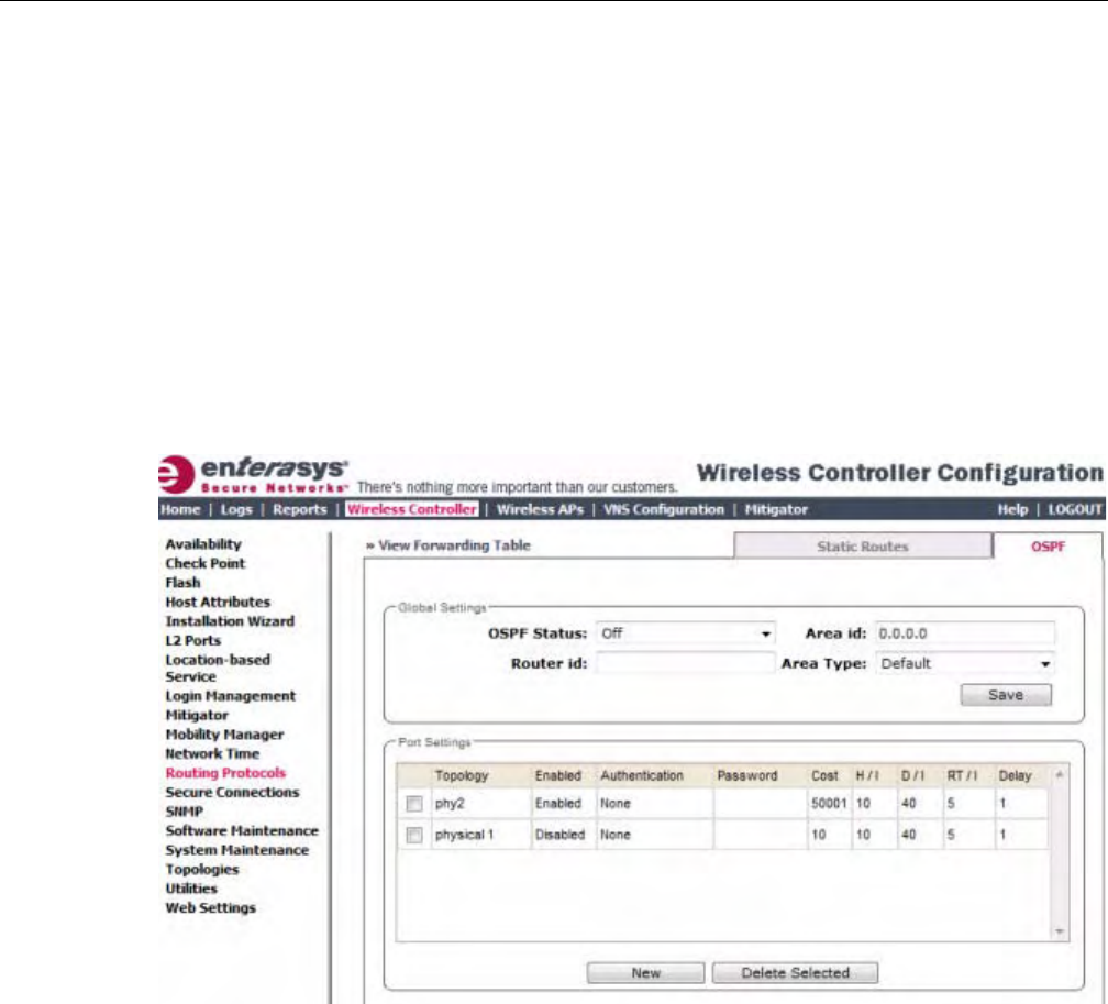
Configuring the Enterasys Wireless Controller for the First Time
User Guide, V8.01 2-25
EnsurethattheOSPFparametersdefinedherefortheEnterasysWirelessControllerareconsistent
withtheadjacentroutersintheOSPFarea.Thisconsistencyincludesthefollowing:
•Ifthepeerrouterhasdifferenttimersettings,theprotocoltimersettingsintheEnterasys
WirelessControllermustbechangedtomatchtoachieveOSPFadjacency.
•TheMTUoftheportsoneitherendofanOSPFlinkmustmatch.TheMTUforportsonthe
EnterasysWirelessControllerisfixedat1500.ThismatchesthedefaultMTUinstandard
routers.
To Set OSPF Routing Global Settings on the Enterasys Wireless Controller:
1. Fromthetopmenu,clickWirelessController.TheWirelessControllerConfigurationscreen
isdisplayed.
2. Intheleftpane,clickRoutingProtocols.TheStaticRoutestabisdisplayedbydefault.
3. ClicktheOSPFtab.
4. FromtheOSPFStatusdrop‐downlist,clickOntoenableOSPF.
IntheRouterIDbox,typetheIPaddressoftheEnterasysWirelessController.ThisIDmust
beuniqueacrosstheOSPFarea.Ifleftblank,theOSPFdaemonautomaticallypicksarouter
IDfromoneoftheEnterasysWirelessController’sinterfaceIPaddresses.
5. IntheAreaIDbox,typethearea.0.0.0.0isthemainareainOSPF.
6. IntheAreaTypedrop‐downlist,clickoneofthefollowing:
–Default—Thedefaultactsasthebackbonearea(alsoknownasareazero).Itformsthe
coreofanOSPFnetwork.Allotherareasareconnectedtoit,andinter‐arearouting
happensviaarouterconnectedtothebackbonearea.
–Stub—Thestubareadoesnotreceiveexternalroutes.Externalroutesaredefinedas
routeswhichweredistributedinOSPFviaanotherroutingprotocol.Therefore,stubareas
typicallyrelyonadefaultroutetosendtrafficroutesoutsidethepresentdomain.
–Not‐so‐stubby—Thenot‐so‐stubbyareaisatypeofstubareathatcanimport
autonomoussystem(AS)externalroutesandsendthemtothedefault/backbonearea,but
cannotreceiveASexternalroutesfromthebackboneorotherareas.
DRAFT
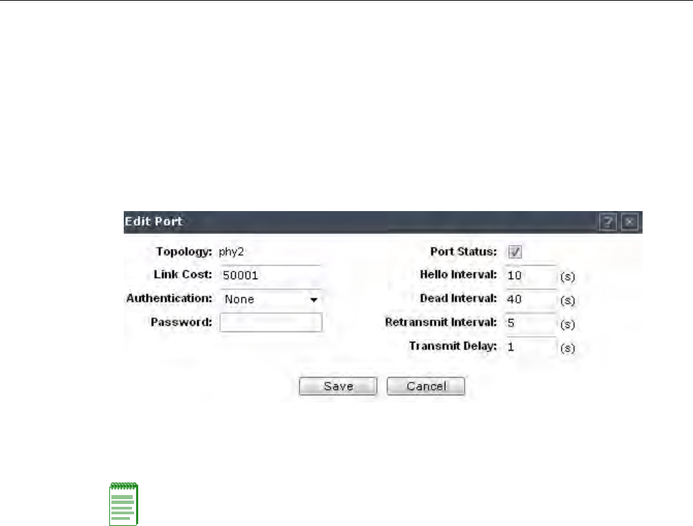
Configuring the Enterasys Wireless Controller for the First Time
2-26 Configuring the Enterasys Wireless Controller
7. Tosaveyourchanges,clickSave.
To Set OSPF Routing Port Settings on the Enterasys Wireless Controller:
1. Fromthetopmenu,clickWirelessController.TheWirelessControllerConfigurationscreen
isdisplayed.
2. Intheleftpane,clickRoutingProtocols.
3. ClicktheOSPFtab.
4. SelectaporttoconfigurebyclickingonthedesiredportinthePortSettingstable.TheEdit
Portdialogdisplays.
5. IntheLinkCostbox,typetheOSPFstandardvalueforyournetworkforthisport.Thisisthe
costofsendingadatapacketontheinterface.Thelowerthecost,themorelikelytheinterface
istobeusedtoforwarddatatraffic.
6. IntheAuthenticationdrop‐downlist,clicktheauthenticationtypeforOSPFonyournetwork:
NoneorPassword.ThedefaultsettingisNone.
7. IfPasswordisselectedastheauthenticationtype,inthePasswordbox,typethepassword.
IfNoneisselectedastheAuthenticationtype,leavethisboxempty.Thispasswordmust
matchoneitherendoftheOSPFconnection.
8. Typethefollowing:
–Hello‐Interval—Specifiesthetimeinseconds(displaysOSPFdefault).Thedefaultsetting
is10seconds.
–Dead‐Interval—Specifiesthetimeinseconds(displaysOSPFdefault).Thedefault
settingis40seconds.
–Retransmit‐Interval—Specifiesthetimeinseconds(displaysOSPFdefault).Thedefault
settingis5seconds.
–TransmitDelay—Specifiesthetimeinseconds(displaysOSPFdefault).Thedefault
settingis1second.
9. Tosaveyourchanges,clickSave.
To Confirm That Ports Are Set for OSPF:
1. ToconfirmthattheportsaresetupforOSPF,andthatadvertisedroutesfromtheupstream
routerarerecognized,clickViewForwardingTable.TheForwardingTableisdisplayed.
Note: If more than one port is enabled for OSPF, it is important to prevent the Enterasys Wireless
Controller from serving as a router for other network traffic (other than the traffic from wireless
device users on routed topologies controlled by the Enterasys Wireless Controller). For more
information, see “Filtering Rules” on page 5-3.
DRAFT

Configuring the Enterasys Wireless Controller for the First Time
User Guide, V8.01 2-27
ThefollowingadditionalreportsdisplayOSPFinformationwhentheprotocolisinoperation:
–OSPFNeighbor—DisplaysthecurrentneighborsforOSPF(routersthathaveinterfaces
toacommonnetwork)
–OSPFLinkstate—DisplaystheLinkStateAdvertisements(LSAs)receivedbythe
currentlyrunningOSPFprocess.TheLSAsdescribethelocalstateofarouterornetwork,
includingthestateoftherouter’sinterfacesandadjacencies.
2. Toupdatethedisplay,clickRefresh.
Configuring Filtering at the Interface Level
TheEnterasysWirelesssolutionhasanumberofbuilt‐infiltersthatprotectthesystemfrom
unauthorizedtraffic.ThesefiltersarespecificonlytotheEnterasysWirelessController.These
filtersareappliedatthenetworkinterfacelevelandareautomaticallyinvoked.Bydefault,these
filtersprovidestringent‐levelrulestoallowonlyaccesstothesystemʹsexternallyvisibleservices.
Inadditiontothesebuilt‐infilters,theadministratorcandefinespecificexceptionfiltersatthe
interface‐leveltocustomizenetworkaccess.ThesefiltersdependonTopologyModesandthe
configurationofanL3interfaceforthetopology.
ForBridgedatControllertopologies,exceptionfiltersaredefinedonlyifL3(IP)interfacesare
specified.ForPhysical,Routed,and3rdPartyAPtopologies,exceptionfilteringisalways
configuredsincetheyallhaveanL3interfacepresence.
Built-in Interface-based Exception Filters
OntheEnterasysWirelessController,variousinterface‐basedexceptionfiltersarebuiltinand
invokedautomatically.ThesefiltersprotecttheEnterasysWirelessControllerfromunauthorized
accesstosystemmanagementfunctionsandservicesviatheinterfaces.Accesstosystem
managementfunctionsisgrantediftheadministratorselectstheallowmanagementtrafficoption
inaspecifictopology.
AllowmanagementtrafficispossibleonthetopologiesthathaveL3IPinterfacedefinitions.For
example,ifmanagementtrafficisallowedonaphysicaltopology(esa0),onlyusersconnected
throughESA0willbeabletogetaccesstothesystem.Usersconnectingonanyothertopology,
suchasRoutedorBridgedLocallyatController,willnolongerbeabletotargetESA0togain
managementaccesstothesystem.Toallowaccessforusersconnectedonsuchatopology,the
giventopologyconfigurationitselfmusthaveallowmanagementtrafficenabledanduserswill
onlybeabletotargetthetopologyinterfacespecifically.
OntheEnterasysWirelessController’sL3interfaces(associatedwitheitherphysical,Routed,or
BridgedLocallyatControllertopologies),thebuilt‐inexceptionfilterprohibitsinvokingSSH,
HTTPS,orSNMP.However,suchtrafficisallowed,bydefault,onthemanagementport.
Ifmanagementtrafficisexplicitlyenabledforanyinterface,accessisimplicitlyextendedtothat
interfacethroughanyoftheotherinterfaces(VNS).Onlytrafficspecificallyallowedbythe
interface’sexceptionfilterisallowedtoreachtheEnterasysWirelessControlleritself.Allother
trafficisdropped.Exceptionfiltersaredynamicallyconfiguredandregeneratedwheneverthe
systemʹsinterfacetopologychanges(forexample,achangeofIPaddressforanyinterface).
Enablingmanagementtrafficonaninterfaceaddsadditionalrulestotheexceptionfilter,which
opensupthewell‐knownIP(TCP/UDP)ports,correspondingtotheHTTPS,SSH,andSNMP
applications.
Theinterface‐basedbuilt‐inexceptionfilteringrules,inthecaseoftrafficfromwirelessusers,are
applicabletotraffictargeteddirectlyforthetopologyL3interface.Forexample,afilterspecified
byaPolicymaybegenericenoughtoallowtrafficaccesstotheEnterasysWirelessControllerʹs
management(forexample,AllowAll[*.*.*.*]).Exceptionfilterrulesareevaluatedaftertheuserʹs
DRAFT
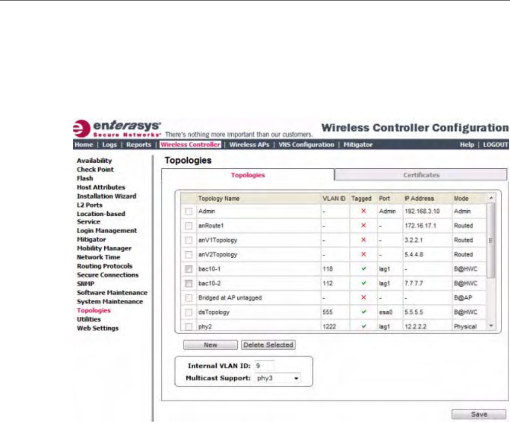
Configuring the Enterasys Wireless Controller for the First Time
2-28 Configuring the Enterasys Wireless Controller
assignedfilterpolicy,assuch,itispossiblethatthepolicyallowstheaccesstomanagement
functionsthattheexceptionfilterdenies.Thesepacketsaredropped.
To Enable SSH, HTTPS, or SNMP Access Through a Physical Data Interface:
1. Fromthetopmenu,clickWirelessController.TheWirelessControllerConfigurationscreen
isdisplayed.
2. Intheleftpane,clickTopologies.TheTopologiestabisdisplayed.
3. OntheTopologiestab,clicktheappropriatedataporttopology.TheEditTopologywindow
displays.
4. SelecttheManagementTrafficcheckboxifthetopologyhasspecifiedanL3IPinterface
presence.
5. Tosaveyourchanges,clickSave.
Working with Administrator-defined Interface-based Exception Filters
Youcanaddspecificfilteringrulesattheinterfacelevelinadditiontothebuilt‐inrules.Suchrules
giveyouthecapabilityofrestrictingaccesstoaport,forspecificreasons,suchasaDenialof
Service(DoS)attack.
ThefilteringrulesaresetupinthesamemannerasfilteringrulesdefinedforaPolicy—specifyan
IPaddress,selectaprotocolifapplicable,andtheneitherallowordenytraffictothataddress.For
moreinformation,see“FilteringRules”onpage 5‐3.
Therulesdefinedforportexceptionfiltersareprependedtothenormalsetofrestrictiveexception
filtersandhaveprecedenceoverthesystemʹsnormalprotectionenforcement(thatis,theyare
evaluatedfirst).
DRAFT
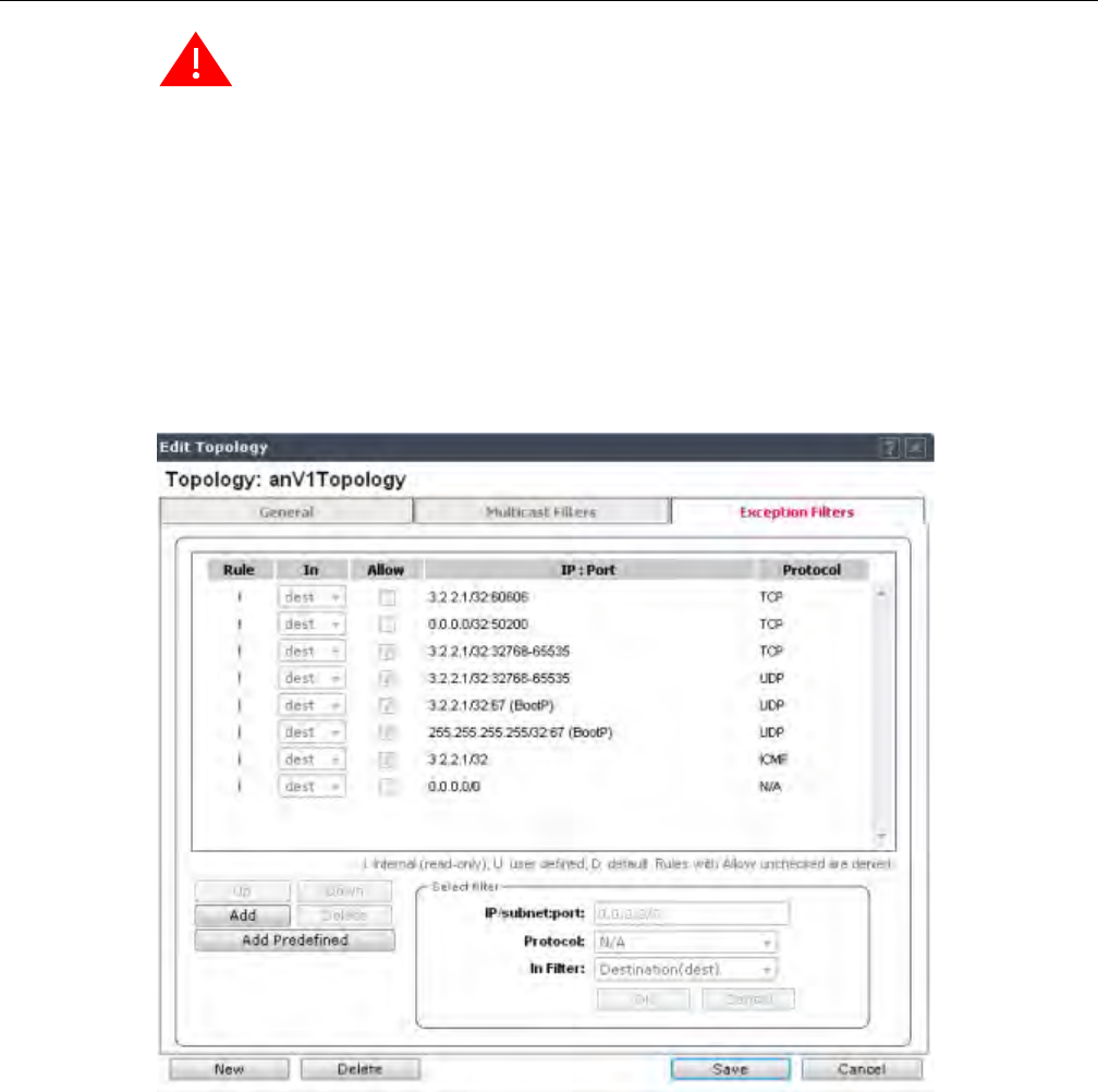
Configuring the Enterasys Wireless Controller for the First Time
User Guide, V8.01 2-29
To Define Interface Exception Filters:
1. Fromthetopmenu,clickWirelessController.TheWirelessControllerConfigurationscreen
isdisplayed.
2. Intheleftpane,clickTopologies.TheTopologiesscreenisdisplayed.
3. Selectatopologytobeconfigured.TheEditTopologywindowisdisplayed.
4. IfthetopologyhasanL3interfacedefined,anExceptionFilterstabisavailable.Selectthistab.
TheExceptionFilterrulesaredisplayed.
Warning: If defined improperly, user exception rules may seriously compromise the system’s
normal security enforcement rules. They may also disrupt the system's normal operation and even
prevent system functionality altogether. It is advised to only augment the exception-filtering
mechanism if absolutely necessary.
DRAFT
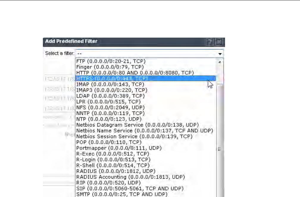
Configuring the Enterasys Wireless Controller for the First Time
2-30 Configuring the Enterasys Wireless Controller
5. Addrulesbyeither:
–ClickingtheAddPredefinedbutton,selectingafilterfromthedropdownlist,and
clickingAdd.
–ClickingtheAddbutton,fillinginthefollowingfields,thenclickingOK:
(1) IntheIP/subnet:portbox,typethedestinationIPaddress.YoucanalsospecifyanIP
range,aportdesignation,oraportrangeonthatIPaddress.
(2) IntheProtocoldrop‐downlist,clicktheprotocolyouwanttospecifyforthefilter.
ThislistmayincludeUDP,TCP,GRE,IPsec‐ESP,IPsec‐AH,ICMP.ThedefaultisN/
A.
6. Thenewfilterisdisplayedintheuppersectionofthescreen.
7. Clickthenewfilterentry.
8. Toallowtraffic,selecttheAllowcheckbox.
9. Toadjusttheorderofthefilteringrules,clickUporDowntopositiontherule.Thefiltering
rulesareexecutedintheorderdefinedhere.
10. Tosaveyourchanges,clickSave.
Protecting the Controller’s Interfaces and Internal Captive Portal Page
Bydefault,theEnterasysWirelessControllerisshippedwithaself‐signedcertificateusedto
performthefollowingtasks:
•ProtectallinterfacesthatprovideadministrativeaccesstotheEnterasysWirelessController
•ProtecttheinternalCaptivePortalpage
ThiscertificateisassociatedwithtopologiesthathaveaconfiguredL3(IP)interface.
IfyoucontinuetousethedefaultcertificatetosecuretheEnterasysWirelessControllerand
internalCaptivePortalpage,yourWebbrowserwilllikelyproducesecuritywarningsregarding
DRAFT
Configuring the Enterasys Wireless Controller for the First Time
User Guide, V8.01 2-31
thesecurityrisksoftrustingself‐signedcertificates.Toavoidthecertificate‐relatedWebbrowser
securitywarnings,youcaninstallcustomizedcertificatesontheEnterasysWirelessController.
Before Installing a Certificate
Beforeyoucreateandinstallacertificate:
1. Selectacertificateformattoinstall.TheEnterasysWirelessControllersupportsseveraltypes
ofcertificates,asshowninTable 2‐3.
2. Understandhowthecontrollermonitorstheexpirationdateofinstalledcertificates.
TheEnterasysWirelessControllergeneratesanentryintheeventsinformationlogasthe
certificateexpirydateapproaches,basedonthefollowingschedule:15,8,4,2,and1dayprior
toexpiration.Thelogmessagesceasewhenthecertificateexpires.Formoreinformation,see
theEnterasysWirelessConvergenceSoftwareMaintenanceGuide.
3. Understandhowthecontrollermanagescertificatesduringupgradesandmigrations.
InstalledcertificateswillbebackedupandrestoredwiththeEnterasysWirelessController
configurationdata.Installedcertificateswillalsobemigratedduringanupgradeandduringa
migration.
Installing a Certificate for a Enterasys Wireless Controller Interface
YoucaninstallacertificatefromtheCertificatestabavailableontheTopologiespage.
To Install a Certificate for a Enterasys Wireless Controller Data Interface:
1. Fromthetopmenu,clickWirelessController.TheWirelessControllerConfigurationscreen
isdisplayed.
2. Intheleftpane,clickTopologies.TheTopologiestabisdisplayed.
3. ClicktheCertificatestab.
Note: To avoid the certificate-related Web browser security warnings when accessing the
Enterasys Wireless Assistant, you must also import the customized certificates into your Web
browser application.
Table 2-3 Supported Certificate and CA Formats
Certificate Format Description
PKCS#12 The PKCS#12 certificate (.pfx) file contains both a certificate and
the corresponding private key.
The Enterasys Wireless Controller will accept the PKCS#12 file as
long as the format of the private key and certificate are valid.
PEM/DER The PEM/DER certificate (.crt) file requires a separate PEM/DER
private key (.key) file. The Enterasys Wireless Controller uses
OpenSSL PKCS12 command to convert the .crt and .key files into
a single .pfx PKCS#12 certificate file.
The Enterasys Wireless Controller will accept the PEM/DER file
as long as the format of the private key and certificate are valid.
PEM-formatted CA public certificate
file
If you choose to install this optional certificate, you must do so
when specifying the PCKCS#12 or PEM/DER certificates.
Note:WhengeneratingthePKCS#12certificatefileorPEM/DERcertificateandkeyfiles,
youmustensurethattheinterfaceidentifiedinthecertificatecorrespondstothe
EnterasysWirelessController’sinterfaceforwhichthecertificateisbeinginstalled.
DRAFT
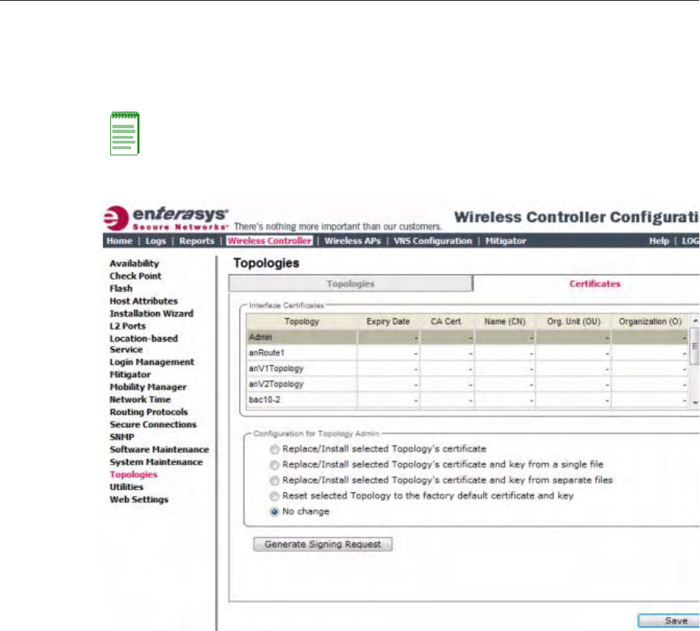
Configuring the Enterasys Wireless Controller for the First Time
2-32 Configuring the Enterasys Wireless Controller
4. IntheInterfaceCertificatestable,clicktoselectthetopology(whichhasanL3interface)for
whichyouwanttoinstallacertificate.
TheConfigurationforTopologiessectionandtheGenerateSigningRequestbuttonbecome
available.UsethefieldandbuttondescriptionsinTable 2‐4tocreateandinstallcertificates.
TheConfigurationforTopologiessectiondisplays.
Note: The interface identified in the certificate must correspond to the Enterasys Wireless
Controller’s interface for which the certificate is being installed.
DRAFT

Configuring the Enterasys Wireless Controller for the First Time
User Guide, V8.01 2-33
Table 2-4 Topologies Page: Certificates Tab Fields and Buttons
Field/Button Description
Interface Certificates
Topology Topology name
Expiry Date Date when the certificate expires
CA Cert. Identifies whether or not a CA certificate has been installed on the
topology.
Name (CN) The IP address of DNS address associated with the topology that
the certificate applies to.
Org Unit (OU) Name of the organization’s unit.
Organization Name of the organization
Configuration for Topology
Replace/Install selected Topology’s
certificate
To replace the existing port’s certificate and key using this option,
do the following:
1. From the click the Generate Signing Request button to create
the certificate and key.
2. Download the key and CSR when prompted.
3. Use a 3rd party certificate service to sign the CSR and create a
certificate and a Certificate Authority (CA) file.
4. Save the certificate on your computer.
5. Return to the Certificates tab on the Enterasys Wireless
Assistant UI.
6. Select the topology for which you created the certificate and
select Replace/Install selected Topologies certificate.
7. Click Browse next to the Signed certificate to install box.
8. Navigate to the certificate file you want to install for this port,
and then click Open. The certificate file name is displayed in
the Certificate file to install box.
9. (Optional) Click Browse next to the Optional:Enter PEM-
encoded CA public certificates file box. The Choose file
dialog is displayed.
10.(Optional) Navigate to the certificate file you want to install for
this port, and then click Open. The certificate file name is
displayed in the Optional:Enter PEM-encoded CA public
certificates file box.
Note: If you choose to install a CA public certificate, you must
install it when you install the PEM/DER certificate and key.
DRAFT

Configuring the Enterasys Wireless Controller for the First Time
2-34 Configuring the Enterasys Wireless Controller
Replace/Install selected Topology’s
certificate and key from a single file
To replace the existing port’s certificate and key using this option,
do the following:
1. Click Browse next to the PKCS #12 file to install box. The
Choose file dialog is displayed.
2. Navigate to the certificate file you want to install for this port,
and then click Open. The certificate file name is displayed in
the PKCS #12 file to install box.
3. In the Private key password box, type the password for the
key file. The key file is password protected.
4. (Optional) Click Browse next to the Optional:Enter PEM-
encoded CA public certificates file box. The Choose file
dialog is displayed.
5. (Optional) Navigate to the certificate file you want to install for
this port, and then click Open. The certificate file name is
displayed in the Optional:Enter PEM-encoded CA public
certificates file box.
Note: If you choose to install a CA public certificate, you must
install it when you install the PEM/DER certificate and key.
Replace/Install selected Topology’s
certificate and key from separate files
To replace the existing port’s certificate and key using this option,
do the following:
1. Click Browse next to the PKCS #12 file to install box. The
Choose file dialog is displayed.
2. Navigate to the certificate file you want to install for this port,
and then click Open. The certificate file name is displayed in
the PKCS #12 file to install box.
3. Click Browse next to the Private key file to install box. The
Choose file dialog is displayed.
4. Navigate to the key file you want to install for this port, and then
click Open. The key file name is displayed in the Private key
file to install box
5. In the Private key password box, type the password for the
key file. The key file is password protected.
6. (Optional) Click Browse next to the Optional:Enter PEM-
encoded CA public certificates file box. The Choose file
dialog is displayed.
7. (Optional) Navigate to the certificate file you want to install for
this port, and then click Open. The certificate file name is
displayed in the Optional:Enter PEM-encoded CA public
certificates file box.
Note: If you choose to install a CA public certificate, you must
install it when you install the PEM/DER certificate and key.
Reset selected Topology to the factory
default certificate and key
Select to assign the factory default certificate and key to the
interface.
No change The default setting.
Generate Signing Request TogenerateaCSRforthecontroller,clickGenerate
SigningRequest.TheGenerateCertificateSigning
Requestwindowdisplays(Figure 2‐3)
Save Click to save the changes to this Topology.
Table 2-4 Topologies Page: Certificates Tab Fields and Buttons (continued)
Field/Button Description
DRAFT
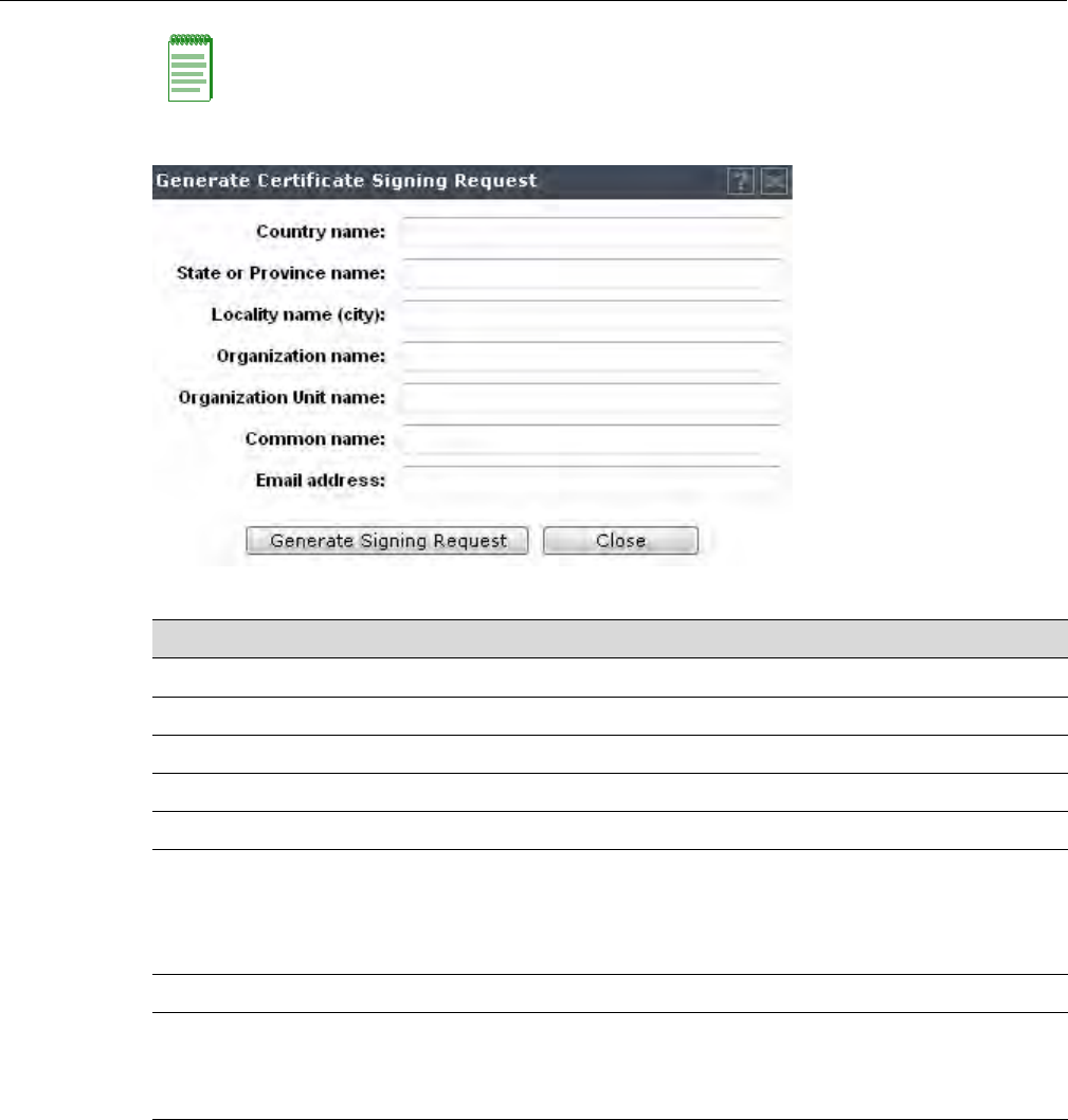
Configuring the Enterasys Wireless Controller for the First Time
User Guide, V8.01 2-35
Figure 2-3 Generate Certificate Signing Request Window
Configuring the Login Authentication Mode
Youcanconfigurethefollowingloginauthenticationmodestoauthenticateadministratorlogin
attempts:
•Localauthentication—TheEnterasysWirelessControlleruseslocallyconfiguredlogin
credentialsandpasswords.See“ConfiguringtheLocalLoginAuthenticationModeand
AddingNewUsers”onpage 2‐36.
•RADIUSauthentication—TheEnterasysWirelessControlleruseslogincredentialsand
passwordsconfiguredonaRADIUSserver.See“ConfiguringtheRADIUSLogin
AuthenticationMode”onpage 2‐38.
Note: To avoid the certificate-related Web browser security warnings when accessing the
Enterasys Wireless Assistant, you must also import the customized certificates into your Web
browser application.
Table 2-5 Generate Certificate Signing Request Page - Fields and Buttons
Field/Button Description
Country name The two-letter ISO abbreviation of the name of the country
State or Province name The name of the State/Province
Locality name (city) The name of the city.
Organization name The name of the organization
Organizational Unit name The name of the unit within the organization.
Common Name Set the common name to be one of the following:
the IP address of the interface that the CSR applies to.
a DNS address associated with the IP address of the interface that
the CSR applies to.
Email address The email address of the organization
Generate Signing Request Click to generate a signing request. A certificate request file is
generated (.csr file extension). The name of the file is the IP
address of the topology you created the CSR for. The File
Download dialog is displayed.
DRAFT
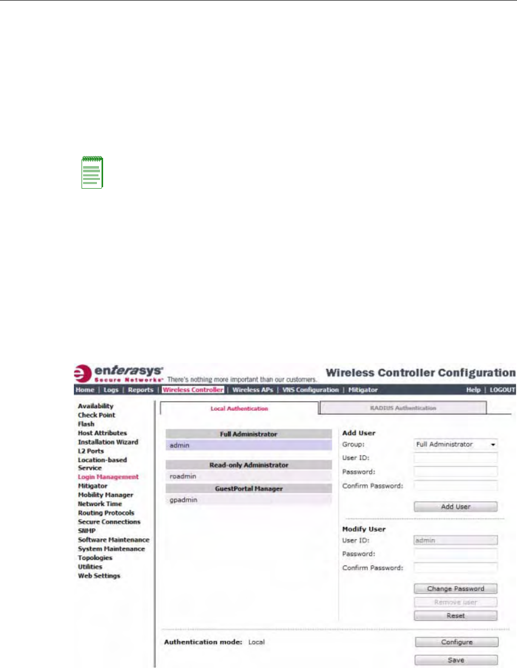
Configuring the Enterasys Wireless Controller for the First Time
2-36 Configuring the Enterasys Wireless Controller
•Localauthenticationfirst,thenRADIUSauthentication—TheEnterasysWirelessController
firstuseslocallyconfiguredlogincredentialsandpasswords.Ifthisloginfails,theEnterasys
WirelessControllerattemptstovalidatelogincredentialsandpasswordsconfiguredona
RADIUSserver.See“ConfiguringtheLocal,RADIUSLoginAuthenticationMode”on
page 2‐42.
•RADIUSauthenticationfirst,thenlocalauthentication—TheEnterasysWirelessController
firstuseslogincredentialsandpasswordsconfiguredonaRADIUSserver.Ifthisloginfails,
theEnterasysWirelessControllerattemptstovalidatelogincredentialsandpasswords
configuredlocally.See“ConfiguringtheRADIUS,LocalLoginAuthenticationMode”on
page 2‐44.
Configuring the Local Login Authentication Mode and Adding New Users
Localloginauthenticationmodeisenabledbydefault.Iftheloginauthenticationwaspreviously
settoanotherauthenticationmode,youcanchangeittothelocalauthentication.Youcanalsoadd
newusersandassignthemtoalogingroup—asfulladministrators,read‐onlyadministrators,or
asaGuestPortalmanagers.Formoreinformation,see“DefiningEnterasysWirelessAssistant
AdministratorsandLoginGroups”onpage 16‐5.
Toconfigurethelocalloginauthenticationmode:
1. Fromthetopmenu,clickWirelessController.TheWirelessControllerConfigurationscreen
isdisplayed.
2. Intheleftpane,clickLoginManagement.TheLoginManagementscreenisdisplayed.
3. IntheAuthenticationmodesection,clickConfigure.
Note: The Enterasys Wireless Convergence Software enables you to recover the Enterasys
Wireless Controller via the Rescue mode if you have lost its login password. For more information,
see the Enterasys Wireless Convergence Software Maintenance Guide.
DRAFT
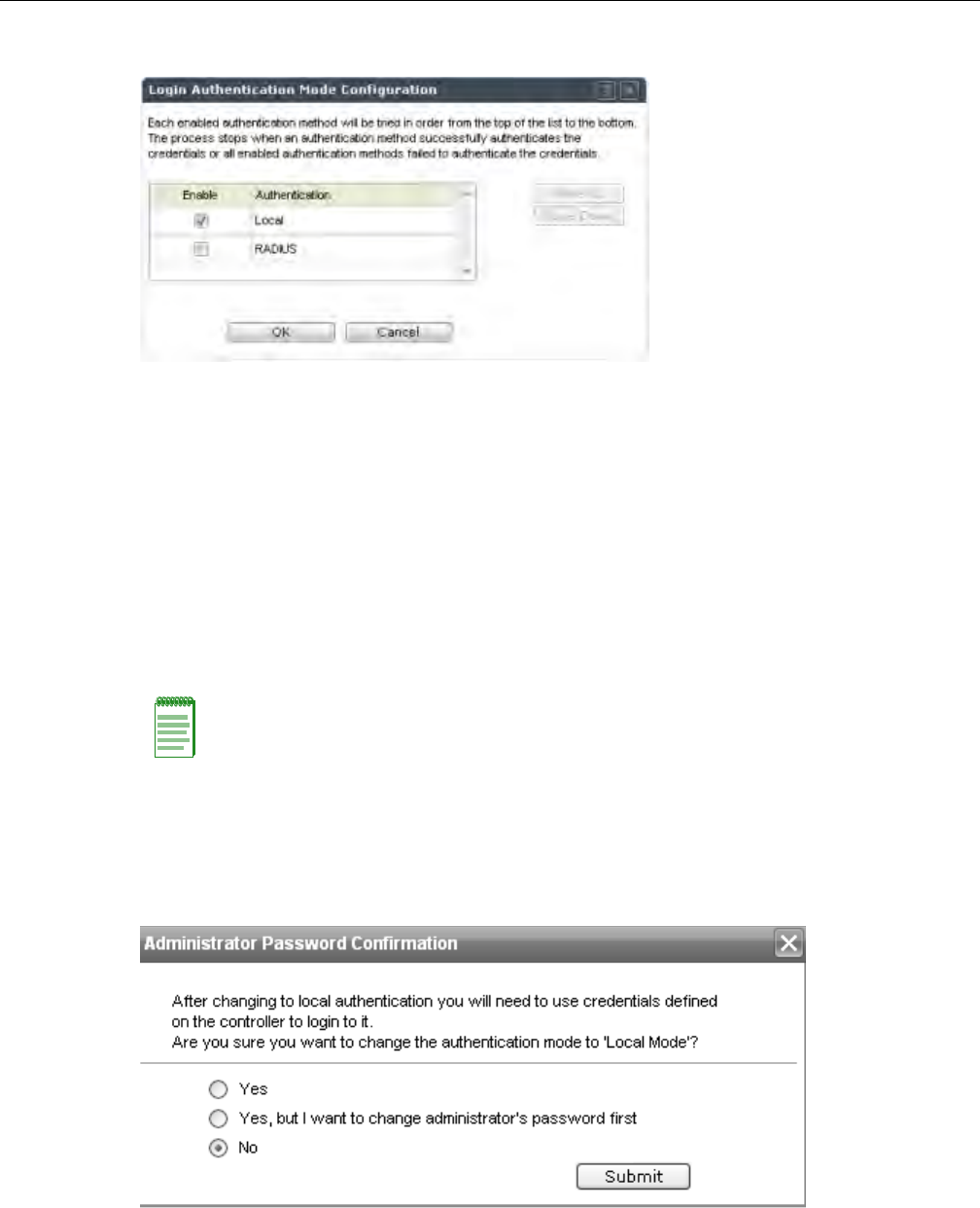
Configuring the Enterasys Wireless Controller for the First Time
User Guide, V8.01 2-37
TheLoginAuthenticationModeConfigurationwindowisdisplayed.
4. SelecttheLocalcheckbox.
IftheRADIUScheckboxisselected,deselectit.
5. ClickOK.
6. IntheAddUsersection,selectoneofthefollowingfromtheGroupdrop‐downlist:
–FullAdministrator—Grantstheadministrator’saccessrightstotheadministrator.
–Read‐onlyAdministrator—Grantsread‐onlyaccessrighttotheadministrator.
–GuestPortalManager—GrantstheuserGuestPortalmanagerrights.
7. IntheUserIDbox,typetheuser’sID.
8. InthePasswordbox,typetheuser’spassword.
9. IntheConfirmPasswordbox,re‐typethepassword.
10. Toaddtheuser,clickAddUser.Thenewuserisadded.
11. ClickSave.
TheAdministratorPasswordConfirmationwindowisdisplayed.
12. Selecttheappropriateoption.
–Yes—Changeauthenticationmodetolocal.Usetheadministratorpasswordcurrently
definedonthecontroller.
Note: The password must be 8 to 24 characters long.
DRAFT

Configuring the Enterasys Wireless Controller for the First Time
2-38 Configuring the Enterasys Wireless Controller
–Yes,butIwanttochangeadministrator’spasswordfirst—Changeauthenticationmode
tolocalandchangetheadministratorpasswordcurrentlydefinedonthecontroller.
–No—Donotchangetheauthenticationmodetolocal.
13. ClickSubmit.
14. IfyouchoseYes,butIwanttochangeadministrator’spasswordfirst,youarepromptedto
changetheadministrator’spassword.
Configuring the RADIUS Login Authentication Mode
Thelocalloginauthenticationmodeisenabledbydefault.Youcanchangethelocallogin
authenticationmodetoRADIUS‐basedauthentication.
RADIUSisaclient/serverauthenticationandauthorizationaccessprotocolusedbyanetwork
accessserver(NAS)toauthenticateusersattemptingtoconnecttoanetworkdevice.TheNAS
functionsasaclient,passinguserinformationtooneormoreRADIUSservers.TheNASpermits
ordeniesnetworkaccesstoauserbasedontheresponseitreceivesfromoneormoreRADIUS
servers.RADIUSusesUserDatagramProtocol(UDP)forsendingthepacketsbetweenthe
RADIUSclientandserver.
YoucanconfigureaRADIUSkeyontheclientandserver.Ifyouconfigureakeyontheclient,it
mustbethesameastheoneconfiguredontheRADIUSservers.TheRADIUSclientsandservers
usethekeytoencryptallRADIUSpacketstransmitted.IfyoudonotconfigureaRADIUSkey,
packetsarenotencrypted.Thekeyitselfisnevertransmittedoverthenetwork.
ToconfiguretheRADIUSloginauthenticationmode:
1. Fromthetopmenu,clickWirelessController.TheWirelessControllerConfigurationscreen
isdisplayed.
2. Intheleftpane,clickLoginManagement.TheLoginManagementscreenisdisplayed.
Note: Before you change the default local login authentication to RADIUS-based authentication,
you must configure the RADIUS Server on the Global Settings screen. For more information, see
“VNS Global Settings” on page 7-3.
Note: Before you configure the system to use RADIUS-based login authentication, you must
configure the Service-Type RADIUS attribute on the RADIUS server.
DRAFT
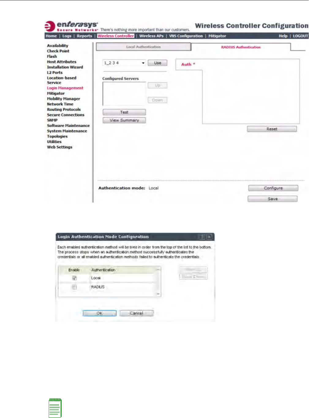
Configuring the Enterasys Wireless Controller for the First Time
User Guide, V8.01 2-39
3. ClicktheRADIUSAuthenticationtab.
4. IntheAuthenticationmodesection,clickConfigure.
TheLoginAuthenticationModeConfigurationwindowisdisplayed.
5. SelecttheRADIUScheckbox.
IftheLocalcheckboxisselected,deselectit.
6. ClickOK.
7. Fromthedrop‐downlist,locatednexttotheUsebutton,selecttheRADIUSServerthatyou
wanttousefortheRADIUSloginauthentication,andthenclickUse.TheRADIUSServer’s
nameisdisplayedintheConfiguredServersbox,andintheAuthsection,andthefollowing
defaultvaluesoftheRADIUSServeraredisplayed.
Note: The RADIUS Servers displayed in the list located against the Use button are defined on
Global Settings screen. For more information, see “VNS Global Settings” on page 7-3.
DRAFT
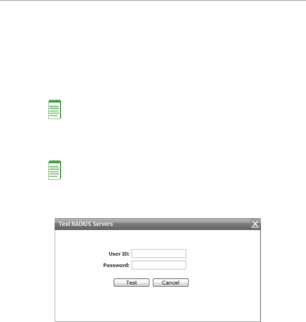
Configuring the Enterasys Wireless Controller for the First Time
2-40 Configuring the Enterasys Wireless Controller
Thefollowingvaluescanbeedited:
–NASIPaddress—TheIPaddressofNetworkAccessServer(NAS).
–NASIdentifier—TheNetworkAccessServer(NAS)identifier.TheNASidentifierisa
RADIUSattributethatidentifiestheserverresponsibleforpassinginformationto
designatedRADIUSservers,andthenactingontheresponsereturned.
–AuthType—Theauthenticationprotocoltype(PAP,CHAP,MS‐CHAP,orMS‐CHAP2).
–SetasPrimaryServer—SpecifiestheprimaryRADIUSserverwhentherearemultiple
RADIUSservers.
8. ToaddadditionalRADIUSservers,repeatStep 7.
9. ClickTesttotestconnectivitytotheRADIUSserver.
Thefollowingwindowisdisplayed.
10. IntheUserIDandthePasswordboxes,typetheuser’sIDandthepassword,whichwere
configuredontheRADIUSServer,andthenclickTest.TheRADIUSconnectivityresultis
displayed.
Note: You can add up to three RADIUS servers to the list of login authentication servers. When you
add two or more RADIUS servers to the list, you must designate one of them as the Primary server.
The Enterasys Wireless Controller first attempts to connect to the Primary server. If the Primary
Server is not available, it tries to connect to the second and third server according to their order in
the Configured Servers box. You can change the order of RADIUS servers in the Configured
Servers box by clicking on the Up and Down buttons.
Note: You can also test the connectivity to the RADIUS server after you save the configuration.
If you do not test the RADIUS server connectivity, and you have made an error in configuring the
RADIUS-based login authentication mode, you will be locked out of the Enterasys Wireless
Controller when you switch the login mode to the RADIUS login authentication mode. If you are
locked out, access Rescue mode via the console port to reset the authentication method to local.
DRAFT
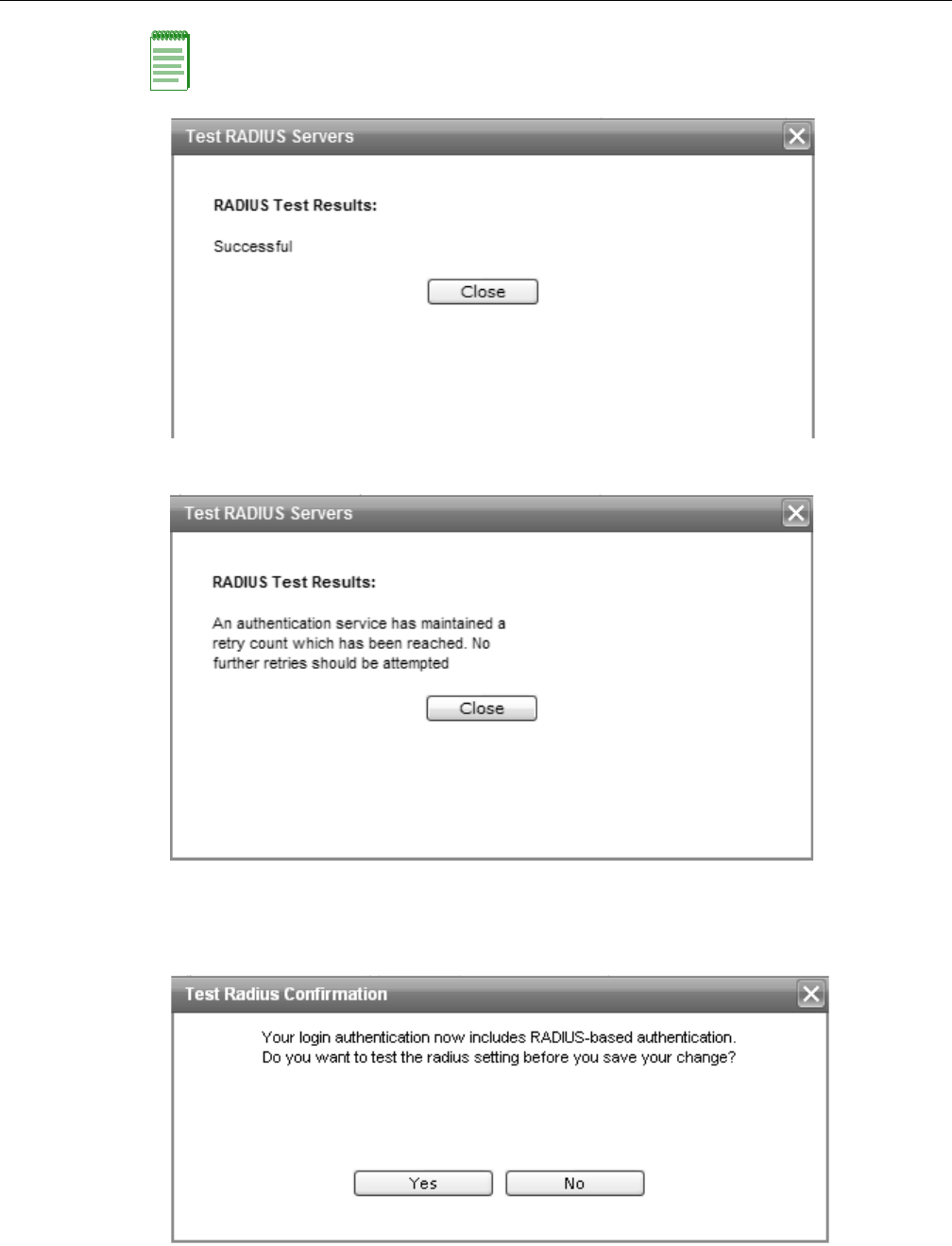
Configuring the Enterasys Wireless Controller for the First Time
User Guide, V8.01 2-41
.
Ifthetestisnotsuccessful,thefollowingmessagewillbedisplayed:
11. IftheRADIUSconnectivitytestdisplays“Successful”result,clickSaveontheRADIUS
Authenticationscreentosaveyourconfiguration.
Thefollowingwindowisdisplayed:
Note: To learn how to configure the User ID and the Password on the RADIUS server, refer to your
RADIUS server’s user guide.
DRAFT
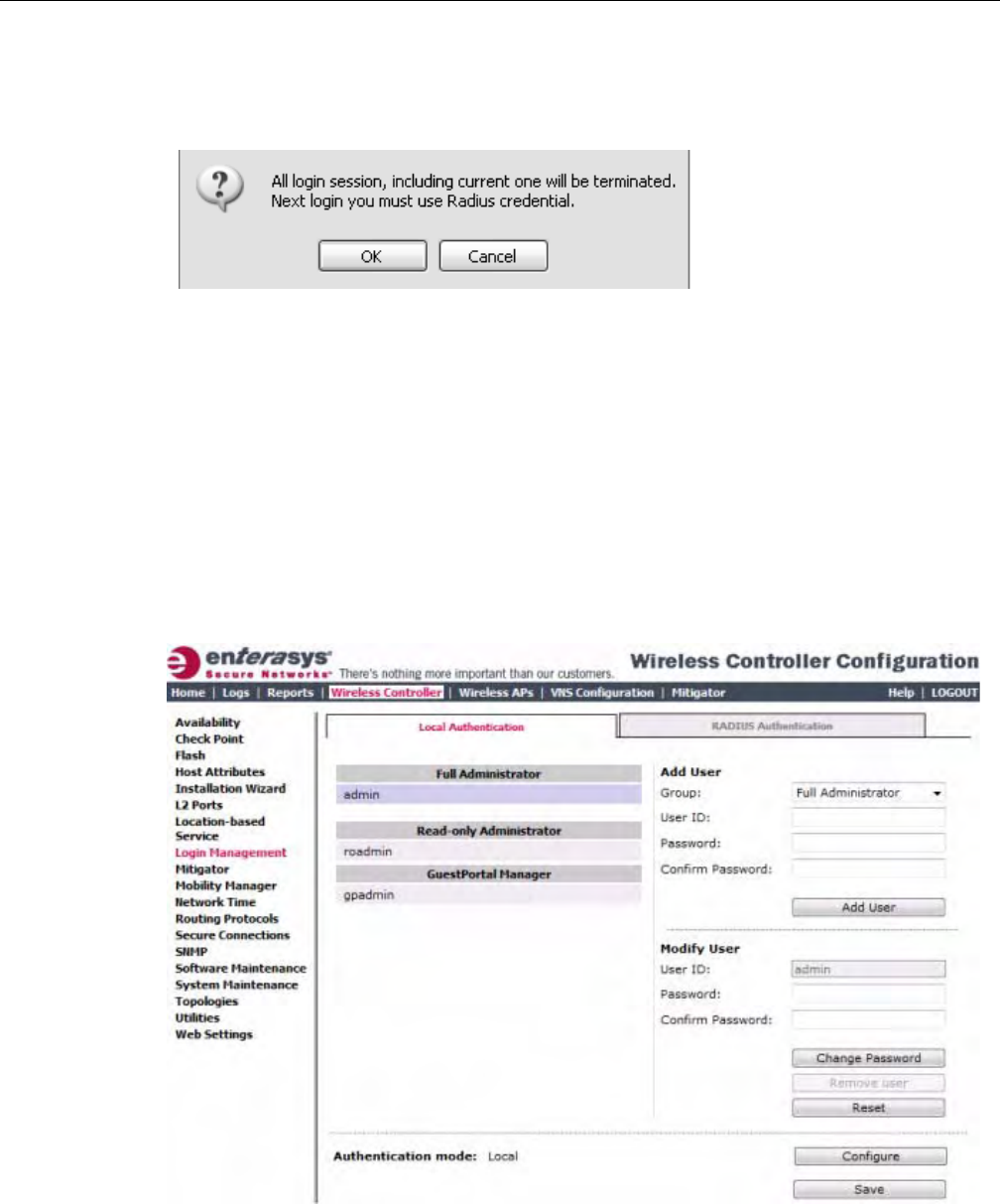
Configuring the Enterasys Wireless Controller for the First Time
2-42 Configuring the Enterasys Wireless Controller
12. IfyoutestedtheRADIUSserverconnectivityearlierinthisprocedure(Step 9andStep 10),
clickNo.IfyouclickYes,youwillbeaskedtoentertheRADIUSserveruserIDandpassword.
SeeStep 10formoreinformation.
Thefollowingmessageisdisplayed:
13. TochangetheauthenticationmodetoRADIUSauthentication,clickOK.
YouwillbeloggedoutoftheEnterasysWirelessControllerimmediately.Youmustusethe
RADIUSloginusernameandpasswordtologontheEnterasysWirelessController.
Tocanceltheauthenticationmodechanges,clickCancel.
Configuring the Local, RADIUS Login Authentication Mode
ToconfiguretheLocal,RADIUSloginauthenticationmode:
1. Fromthetopmenu,clickWirelessController.TheWirelessControllerConfigurationscreen
isdisplayed.
2. Intheleftpane,clickLoginManagement.TheLoginManagementscreenisdisplayed.
3. IntheAuthenticationmodesection,clickConfigure.
DRAFT
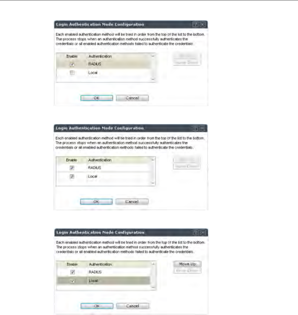
Configuring the Enterasys Wireless Controller for the First Time
User Guide, V8.01 2-43
TheLoginAuthenticationModeConfigurationwindowisdisplayed.
4. SelecttheLocalandRADIUScheckbox.
5. Ifnecessary,selectLocalandusetheMoveUpbuttontomoveLocaltothetopofthelist.
6. ClickOK.
7. OntheLoginManagementscreen,clickSave.
Forinformationonsettinglocalloginauthenticationsettings,see“ConfiguringtheLocalLogin
AuthenticationModeandAddingNewUsers”onpage 2‐36.
ForinformationonsettingRADIUSloginauthenticationsettings,see“ConfiguringtheRADIUS
LoginAuthenticationMode”onpage 2‐38.
DRAFT
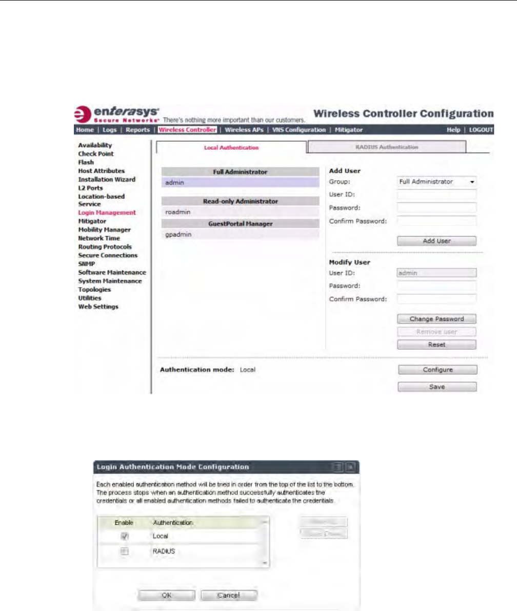
Configuring the Enterasys Wireless Controller for the First Time
2-44 Configuring the Enterasys Wireless Controller
Configuring the RADIUS, Local Login Authentication Mode
ToconfiguretheRADIUS,Localloginauthenticationmode:
1. Fromthetopmenu,clickWirelessController.TheWirelessControllerConfigurationscreen
isdisplayed.
2. Intheleftpane,clickLoginManagement.TheLoginManagementscreenisdisplayed.
3. IntheAuthenticationmodesection,clickConfigure.
TheLoginAuthenticationModeConfigurationwindowisdisplayed.
DRAFT
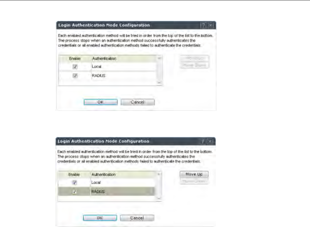
Configuring the Enterasys Wireless Controller for the First Time
User Guide, V8.01 2-45
4. SelecttheLocalandRADIUScheckbox.
5. Ifnecessary,selectRADIUSandusetheMoveUpbuttontomoveRADIUStothetopofthe
list.
6. ClickOK.
7. OntheLoginManagementscreen,clickSave.
ForinformationonsettingRADIUSloginauthenticationsettings,see“ConfiguringtheRADIUS
LoginAuthenticationMode”onpage 2‐38.
Forinformationonsettinglocalloginauthenticationsettings,see“ConfiguringtheLocalLogin
AuthenticationModeandAddingNewUsers”onpage 2‐36.
Configuring SNMP
TheEnterasysWirelessControllersupportstheSimpleNetworkManagementProtocol(SNMP)
forretrievingstatisticsandconfigurationinformation.IfyouenableSNMPontheEnterasys
WirelessController,youcanchooseeitherSNMPv3orSNMPv1/v2mode.Ifyouconfigurethe
EnterasysWirelessControllertouseSNMPv3,thenanyrequestotherthanSNMPv3requestis
rejected.ThesameistrueifyouconfiguretheEnterasysWirelessControllertouseSNMPv1/v2.
To Configure SNMP:
1. Fromthetopmenu,clickWirelessController.TheWirelessControllerConfigurationscreen
isdisplayed.
DRAFT
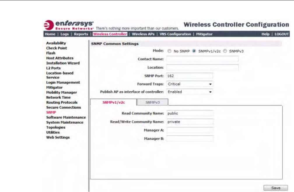
Configuring the Enterasys Wireless Controller for the First Time
2-46 Configuring the Enterasys Wireless Controller
2. Intheleftpane,clickSNMP.TheSNMPscreenisdisplayed.
3. IntheSNMPCommonSettingssection,configurethefollowing:
–Mode—SelectSNMPv1/v2corSNMPv3toenableSNMP.
–ContactName—ThenameoftheSNMPadministrator.
–Location—ThephysicallocationoftheEnterasysWirelessControllerrunningtheSNMP
agent.
–SNMPPort—ThedestinationportfortheSNMPtraps.Possibleportsare
0–65555.
–ForwardTraps—ThelowestseveritylevelofSNMPtrapthatyouwanttoforward.
–PublishAPasinterfaceofcontroller—EnableordisableSNMPpublishingoftheaccess
pointasaninterfacetotheEnterasysWirelessController.
4. ContinuewiththeappropriateprocedureforconfiguringSNMPv1/v2c‐specificorSNMPv3‐
specificparameters.
–ConfiguringSNMPv1/v2c‐specificParameters
–ConfiguringSNMPv3‐specificParameters
Configuring SNMPv1/v2c-specific Parameters
1. ConfigurethefollowingparametersontheSNMPv1/v2ctab:
–ReadCommunityName—Thepasswordthatisusedforread‐onlySNMP
communication.
–Read/WriteCommunityName—ThepasswordthatisusedforwriteSNMP
communication.
DRAFT

Configuring the Enterasys Wireless Controller for the First Time
User Guide, V8.01 2-47
–ManagerA—TheIPaddressoftheserverusedastheprimarynetworkmanagerthatwill
receiveSNMPmessages.
–ManagerB—TheIPaddressoftheserverusedasthesecondarynetworkmanagerthat
willreceiveSNMPmessages.
2. ClickSave.
Configuring SNMPv3-specific Parameters
1. ConfiguretheparametersfollowingontheSNMPv3tab:
–ContextString—AdescriptionoftheSNMPcontext.
–EngineID—TheSNMPv3engineIDfortheEnterasysWirelessControllerrunningthe
SNMPagent.TheengineIDmustbefrom5to32characterslong.
–RFC3411Compliant—TheengineIDwillbeformattedasdefinedbySnmpEngineID
textualconvention(thatis,theengineIDwillbeprependedwithSNMPagentsʹprivate
enterprisenumberassignedbyIANAasaformattedHEXtextstring).
2. ClickAddUserAccount.TheAddSNMPv3UserAccountwindowdisplays.
3. Configurethefollowingparameters:
–User—Enterthenameoftheuseraccount.
–SecurityLevel—Selectthesecuritylevelforthisuseraccount.Choicesare:authPriv,
authNoPriv,noAuthnoPriv.
–AuthProtocol—IfyouhaveselectedasecuritylevelofauthPrivorauthNoPriv,selectthe
authenticationprotocol.Choicesare:MD5,SHA,None.
–AuthPassword—IfyouhaveselectedasecuritylevelofauthPrivorauthNoPriv,enteran
authenticationpassword.
–PrivacyProtocol—IfyouhaveselectedthesecuritylevelofauthPriv,selecttheprivacy
protocol.Choicesare:DES,None
–PrivacyPassword—IfyouhaveselectedthesecuritylevelofauthPriv,enteraprivacy
password.
–EngineID—Ifdesired,enteranengineID.TheIDcanbebetween5and32byteslong,
withnospaces,controlcharacters,ortabs.
–TrapDestination—Ifdesired,entertheIPaddressofatrapdestination.
4. ClickOK.TheAddSNMPv3UserAccountwindowcloses.
5. Repeatsteps2through4toaddadditionalusers.
6. IntheTrap1andTrap2sections,configurethefollowingparameters:
–DestinationIP—TheIPaddressofthemachinemonitoringSNMPv3traps
–UserName—TheSNMPv3usertoconfigureforusewithSNMPv3traps
7. ClickSave.
Editing an SNMPv3 User
To Edit an SNMPv3 User:
1. Fromthetopmenu,clickWirelessController.TheWirelessControllerConfigurationscreen
isdisplayed.
2. Intheleftpane,clickSNMP.TheSNMPscreenisdisplayed.
DRAFT

Configuring the Enterasys Wireless Controller for the First Time
2-48 Configuring the Enterasys Wireless Controller
3. ClicktheSNMPv3tab.
4. SelectanSNMPuser.
5. ClickEditSelectedUser.TheEditSNMPv3UserAccountwindowdisplays.
6. Edittheuserconfigurationasdesired.
7. ClickOK.TheEditSNMPv3UserAccountwindowcloses.
8. ClickSave.
Deleting an SNMPv3 User
To Delete an SNMPv3 User:
1. Fromthetopmenu,clickWirelessController.TheWirelessControllerConfigurationscreen
isdisplayed.
2. Intheleftpane,clickSNMP.TheSNMPscreenisdisplayed.
3. ClicktheSNMPv3tab.
4. SelectanSNMPuser.
5. ClickDeleteSelectedUser.Youarepromptedtoconfirmthatyouwanttodeletetheselected
user.
6. ClickOK.
Configuring Network Time
YoushouldsynchronizetheclocksoftheEnterasysWirelessControllerandtheWirelessAPsto
ensurethatthelogsandreportsreflectaccuratetimestamps.Formoreinformation,see
Chapter 15,WorkingwithReportsandDisplays.
ThenormaloperationoftheEnterasysWirelessControllerwillnotbeaffectedifyoudonot
synchronizetheclock.Theclocksynchronizationisnecessarytoensurethatthelogsdisplay
accuratetimestamps.Inaddition,clocksynchronizationofnetworkelementsisaprerequisitefor
thefollowingconfiguration:
• MobilityManager
•SessionAvailability
Network Time Synchronization
Networktimeissynchronizedinoneoftwoways:
•Usingthesystem’stime—Thesystem’stimeistheEnterasysWirelessController’stime.
•UsingNetworkTimeProtocol(NTP)—TheNetworkTimeProtocolisaprotocolfor
synchronizingtheclocksofcomputersystemsoverpacket‐switcheddatanetworks.
TheEnterasysWirelessControllerautomaticallyadjustsforanytimechangeduetoDaylight
Savingstime.
Configuring the Network Time Using the System’s Time
To Configure the Network Time, Using the System’s Time:
1. Fromthetopmenu,clickWirelessController.TheWirelessControllerConfigurationscreen
isdisplayed.
DRAFT
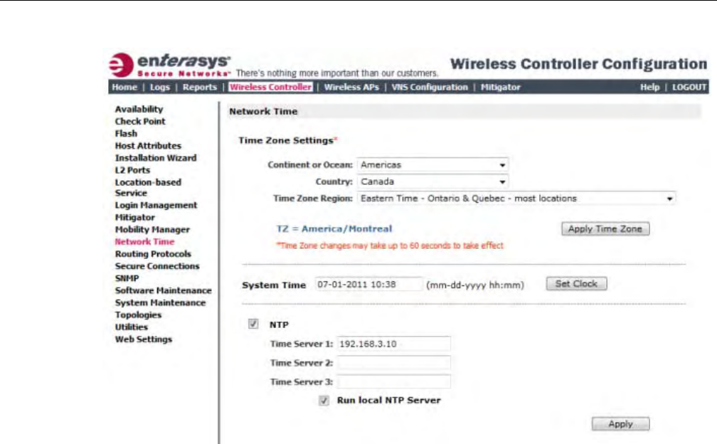
Configuring the Enterasys Wireless Controller for the First Time
User Guide, V8.01 2-49
2. Intheleftpane,clickNetworkTime.TheNetworkTimescreenisdisplayed.
3. FromtheContinentorOceandrop‐downlist,clicktheappropriatelarge‐scalegeographic
groupingforthetimezone.
4. FromtheCountrydrop‐downlist,clicktheappropriatecountryforthetimezone.The
contentsofthedrop‐downlistchange,basedontheselectionintheContinentorOceandrop‐
downlist.
5. FromtheTimeZoneRegiondrop‐downlist,clicktheappropriatetimezoneregionforthe
selectedcountry.
6. ClickApplyTimeZone.
7. IntheSystemTimebox,typethesystemtime.
8. ClickSetClock.
9. TheWLANnetworktimeissynchronizedinaccordancewiththeEnterasysWireless
Controller’stime.
Configuring the Network Time Using an NTP Server
ToconfigurethenetworktimeusinganNTPserver:
1. Fromthetopmenu,clickWirelessController.TheWirelessControllerConfigurationscreen
isdisplayed.
DRAFT
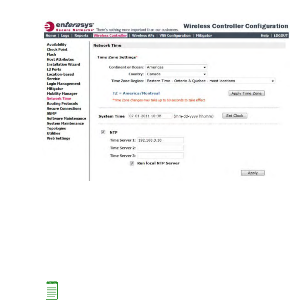
Configuring the Enterasys Wireless Controller for the First Time
2-50 Configuring the Enterasys Wireless Controller
2. Intheleftpane,clickNetworkTime.TheNetworkTimescreenisdisplayed.
3. FromtheContinentorOceandrop‐downlist,clicktheappropriatelarge‐scalegeographic
groupingforthetimezone.
4. FromtheCountrydrop‐downlist,clicktheappropriatecountryforthetimezone.The
contentsofthedrop‐downlistchange,basedontheselectionintheContinentorOceandrop‐
downlist.
5. FromtheTimeZoneRegiondrop‐downlist,clicktheappropriatetimezoneregionforthe
selectedcountry.
6. ClickApplyTimeZone.
7. IntheSystemTimebox,typethesystemtime.
8. SelecttheUseNTPcheckbox.
9. IntheTimeServer1textbox,typetheIPaddressorFQDN(FullQualifiedDomainName)of
anNTPtimeserverthatisaccessibleontheenterprisenetwork.
10. RepeatforTimeServer2andTimeServer3textboxes.
IfthesystemisnotabletoconnecttotheTimeServer1,itwillattempttoconnecttothe
additionalserversthathavebeenspecifiedinTimeServer2andTimeServer3textboxes.
11. ClickApply.
12. TheWLANnetworktimeissynchronizedinaccordancewiththespecifiedtimeserver.
Note: If you want to use the Enterasys Wireless Controller as the NTP Server, select the Run local
NTP Server checkbox, and then skip to Step 11.
DRAFT
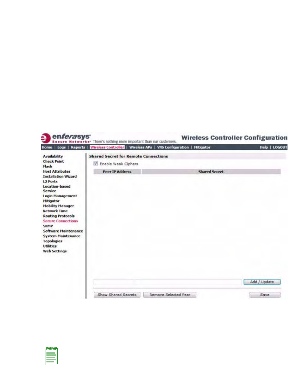
Configuring the Enterasys Wireless Controller for the First Time
User Guide, V8.01 2-51
Configuring Secure Connections
Thecontrollerscommunicateamongstthemselvesusingasecureprotocol.Amongotherthings,
thisprotocolisusedtosharebetweencontrollersthedatarequiredforhighavailability.Theyalso
usethisprotocoltocommunicatewithNMSWirelessManager.Theprotocolrequirestheuseofa
sharedsecretformutualauthenticationoftheendpoints.
BydefaultthecontrollersandNMSWirelessManageruseawellknownfactorydefaultshared
secret.Thismakesiteasytogetupandrunningbutisnotassecureassomesitesrequire.
ThecontrollersandNMSWirelessManagerallowtheadministratortochangethesharedsecret
usedbythesecureprotocol.InfactthecontrollersandWirelessManagercanuseadifferent
sharedsecretforeachindividualendpointtowhichtheyconnectwiththeprotocol.
Toconfigurethesharedsecretforaconnectiononthecontroller:
1. Fromthetopmenu,clickWirelessController.TheWirelessControllerConfigurationscreen
isdisplayed.
2. Intheleftpane,clickSecureConnections.TheSecureConnectionsscreenisdisplayed.
3. EntertheServerIPaddressoftheotherendofthesecureprotocoltunnelandthesharedsecret
touse.
4. ClickAdd/Update.
5. ClickSave.
Note: Configure the same shared secret onto the devices at each end of the connection.
Otherwise, the two controllers or controller and NMS Wireless Manager will not be able to
communicate.
DRAFT
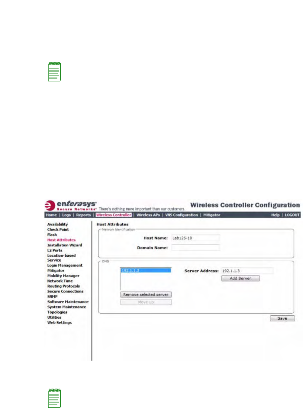
Configuring the Enterasys Wireless Controller for the First Time
2-52 Configuring the Enterasys Wireless Controller
Configuring DNS Servers for Resolving Host Names of NTP and
RADIUS Servers
SincetheGlobalSettingsscreen(topmenu>VNSConfiguration>GlobalSettings)allowsyou
tosetupNTPandRADIUSserversbydefiningtheirhostnames,youhavetoconfigureyourDNS
serverstoresolvethehostnamesofNTPandRADIUSserverstothecorrespondingIPaddresses.
YoucanconfigureuptothreeDNSserverstoresolveNTPandRADIUSserverhostnamestotheir
correspondingIPaddresses.
TheEnterasysWirelessControllersendsthehostnamequerytothefirstDNSserverinthestackof
threeconfiguredDNSservers.TheDNSserverresolvesthequerieddomainnametoanIPaddress
andsendstheresultbacktotheEnterasysWirelessController.
Ifforsomereason,thefirstDNSserverinthestackofconfiguredDNSserversisnotreachable,the
EnterasysWirelessControllersendsthehostnamequerytothesecondDNSserverinthestack.If
thesecondDNSserverisalsonotreachable,thequeryissenttothethirdDNSserverinthestack.
ToconfigureDNSserversforresolvinghostnamesofNTPandRADIUSservers:
1. Fromthetopmenu,clickWirelessController.TheWirelessControllerConfigurationscreen
isdisplayed.
2. Intheleftpane,clickHostAttributes.TheHostAttributesscreenisdisplayed.
3. IntheDNSbox,typetheDNSserver’sIPaddressintheServerAddressfieldandthenclick
AddServer.ThenewserverisdisplayedintheDNSservers’list.
Note: For more information on RADIUS server configuration, see “Defining RADIUS Servers and
MAC Address Format” on page 7-4.
Note: You can configure up to three DNS servers.
DRAFT

Using an AeroScout/Ekahau Location-Based Solution
User Guide, V8.01 2-53
4. Tosaveyourchanges,clickSave.
Using an AeroScout/Ekahau Location-Based Solution
YoucandeployyourEnterasysWirelessControllerandWirelessAPsaspartofanAeroScoutor
Ekahaulocation‐basedsolution.
OntheEnterasysWirelessController,youconfiguretheAeroScout/EkahauserverIPaddressand
enablethelocation‐basedservice.TheAeroScout/EkahauserverisawareonlyoftheEnterasys
WirelessControllerIPaddressandisnotifiedoftheoperationalAPsbytheController.
OntheAPsthatyouwanttoparticipateinthelocation‐basedservice,youenablethelocation‐
basedservice.
Onceyouhaveenabledthelocation‐basedserviceontheEnterasysWirelessControllerandthe
participatingWirelessAPs,atleastoneoftheparticipatingWirelessAPswillreceivereportsfrom
anAeroScout/EkahauWi‐FiRFIDtaginthe2.4GHZband.ThetagreportsarecollectedbytheAP
andforwardedtotheAeroScout/EkahauserverbyencapsulatingthetagreportsinaWASSP
tunnelandroutingthemasIPpacketsthroughtheEnterasysWirelessController.
AnAP’stagreportcollectionstatusisreportedintheWirelessAPInventoryreport.Formore
information,see“ViewingReports”onpage 15‐14.
Ifavailabilityisenabled,tagreporttransmissionpausesonfailedoverAPsuntiltheyare
configuredandnotifiedbytheAeroScout/Ekahauserver.
WhenAeroScout/EkahausupportisdisabledontheEnterasysWirelessController,theEnterasys
WirelessControllerdoesnotcommunicatewiththeAeroScout/EkahauserverandtheAPsdonot
performanyAeroScout/Ekahau‐relatedfunctionality.
EnsurethatyourAeroScout/Ekahautagsareconfiguredtotransmitonallnon‐overlapping
channels(1,6and11)andalsoonchannelsabove11forcountrieswherechannelsabove11are
allowed.RefertoAeroScout/EkahaudocumentationforproperdeploymentoftheAeroScout/
Ekahaulocation‐basedsolution.
To Configure a Enterasys Wireless Controller for Use with an AeroScout/Ekahau
Solution:
1. Fromthetopmenu,clickWirelessController.TheWirelessControllerConfigurationscreen
isdisplayed.
Note: Participating Wireless APs must use the 2.4 GHz band.
Note: Tag reports are marked with UP=CS5, and DSCP = 0xA0. On the Enterasys Wireless
Controller, tag reports are marked with UP=CS5 to the core (if 802.1p exists).
DRAFT
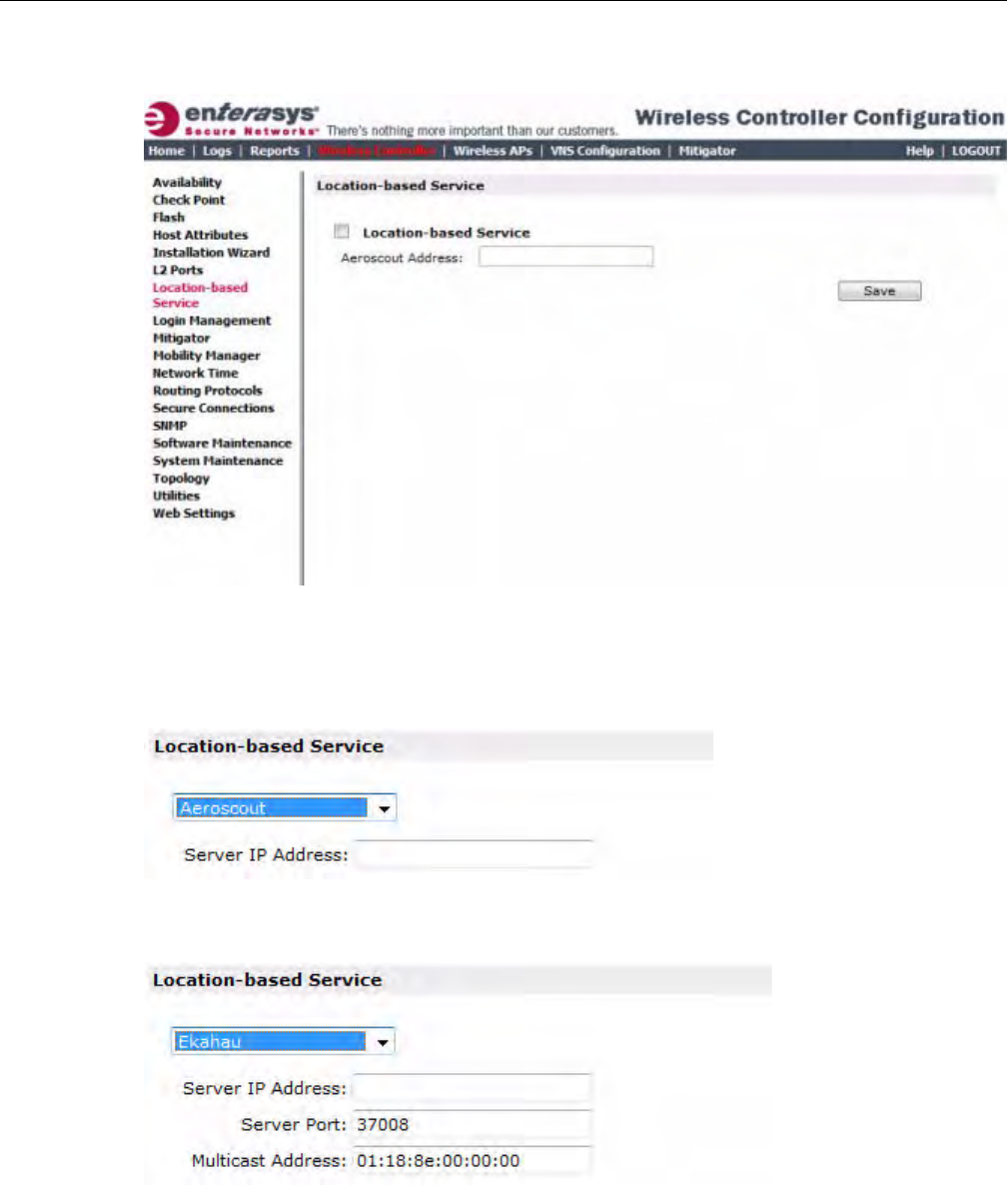
Using an AeroScout/Ekahau Location-Based Solution
2-54 Configuring the Enterasys Wireless Controller
2. Intheleftpane,clickLocation‐basedService.TheLocation‐basedServicescreenis
displayed.
3. FromtheLocation‐basedServicedrop‐downlist,clickthedesiredlocation‐basedservicefor
theEnterasysWirelessController.
4. IfAeroscoutisselected,entertheServerIPAddressoftheAeroScoutserverintheAeroscout
Addressfield.
5. IfEkahauisselected,entertheServerIPAddress,ServerPort,andMulticastAddressofthe
EkahauserverontheEkahauAddressfield.
6. ClickSave.
YoumustnowassignWirelessAPstoparticipateinthelocation‐basedservice.
DRAFT
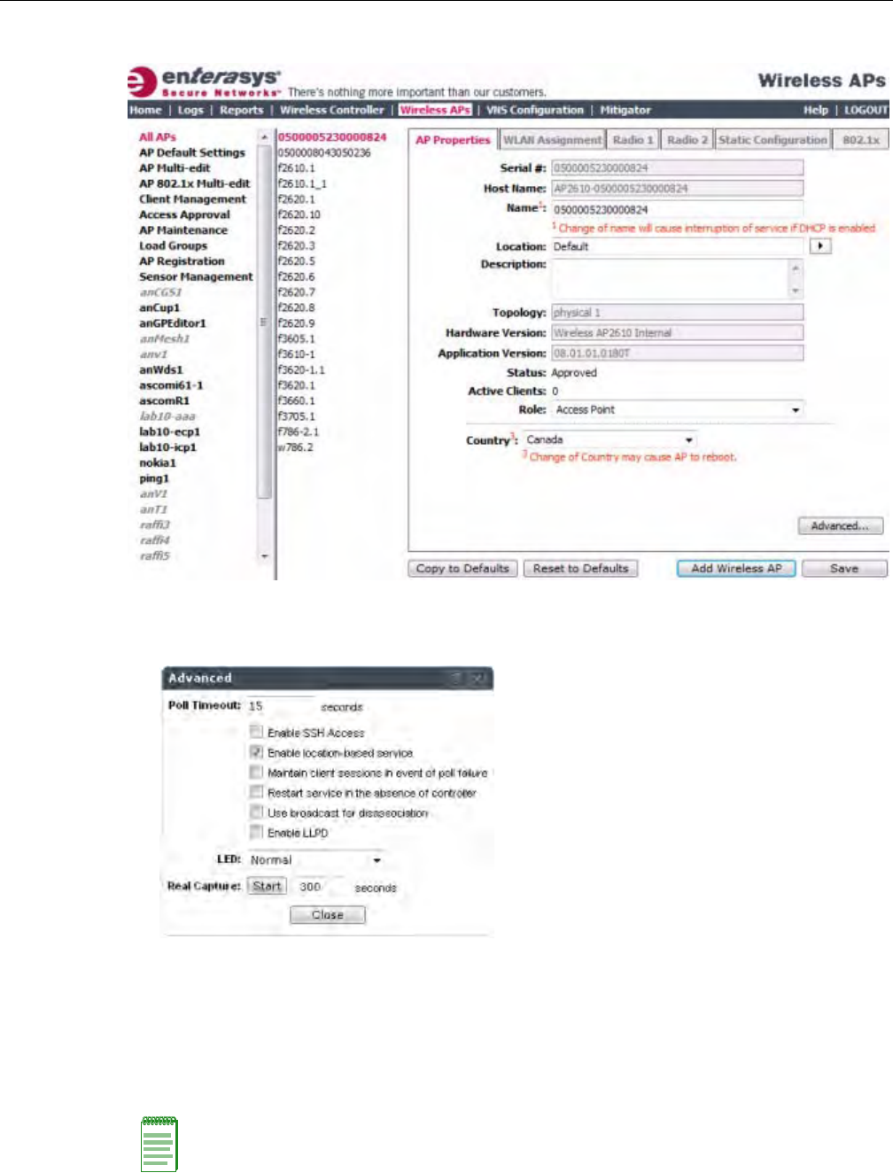
Using an AeroScout/Ekahau Location-Based Solution
User Guide, V8.01 2-55
7. Fromthetopmenu,clickWirelessAPs.TheAllAPsscreenisdisplayed.
8. SelectanAP.
9. ClickAdvanced.TheAdvancedwindowdisplays.
10. SelecttheEnablelocation‐basedservicefield.
11. ClickClose.TheAdvancedwindowcloses.
12. Repeatssteps7through10foreachadditionalAPthatyouwanttoparticipateinthelocation‐
basedservice.
13. ClickSave.
Note: You can also enable location-based service on APs through the Location-based service
field on the AP Multi-edit screen and the Advanced window of the AP Default Settings screen.
DRAFT

Additional Ongoing Operations of the System
2-56 Configuring the Enterasys Wireless Controller
Additional Ongoing Operations of the System
OngoingoperationsoftheEnterasysWirelessConvergenceSoftwaresystemcanincludethe
following:
•EnterasysWirelessControllerSystemMaintenance
•WirelessAPMaintenance
•ClientDisassociate
•LogsandTraces
•ReportsandDisplays
Formoreinformation,seeChapter 16,PerformingSystemAdministrationortheEnterasys
WirelessConvergenceSoftwareMaintenanceGuide.
DRAFT

User Guide, V8.01 3-1
3
Configuring the Wireless AP
ThischapterdescribestheWirelessAccessPoint(AP)andtheEnterasysWirelessConvergence
Softwaresolution,including:
Wireless AP Overview
TheWirelessAPusesthe802.11wirelessstandards(802.11a/b/g/n)fornetworkcommunications
andbridgesnetworktraffictoanEthernetLAN.TheWirelessAPrunsproprietarysoftwarethat
allowsittocommunicateonlywiththeEnterasysWirelessController.
TheWirelessAPphysicallyconnectstoaLANinfrastructureandestablishesanIPconnectionto
theEnterasysWirelessController,whichmanagestheWirelessAPconfigurationthroughthe
EnterasysWirelessAssistant.TheEnterasysWirelessControlleralsoprovidescentralized
management(verificationandupgrade)oftheWirelessAPfirmwareimage.
AUDP‐basedprotocolenablescommunicationbetweentheWirelessAPandtheEnterasys
WirelessController.TheUDP‐basedprotocolencapsulatesIPtrafficfromtheWirelessAPand
directsittotheEnterasysWirelessController.TheEnterasysWirelessControllerdecapsulatesthe
packetsandroutesthemtotheappropriatedestinations,whilemanagingsessionsandapplying
policies.
For information about... Refer to page...
Wireless AP Overview 3-1
Discovery and Registration Overview 3-10
Adding and Registering a Wireless AP Manually 3-28
Configuring Wireless AP Settings 3-29
Configuring VLAN Tags for Wireless APs 3-65
Modifying a Wireless AP’s Properties Based on a Default AP Configuration 3-107
Modifying the Wireless AP’s Default Setting Using the Copy to Defaults
Feature
3-108
Configuring Multiple Wireless APs Simultaneously 3-108
Configuring Co-located APs in Load Balance Groups 3-111
Configuring an AP Cluster 3-117
Converting the Wireless AP to Standalone Mode 3-118
Configuring an AP as a Sensor 3-119
Performing Wireless AP Software Maintenance 3-121
DRAFT
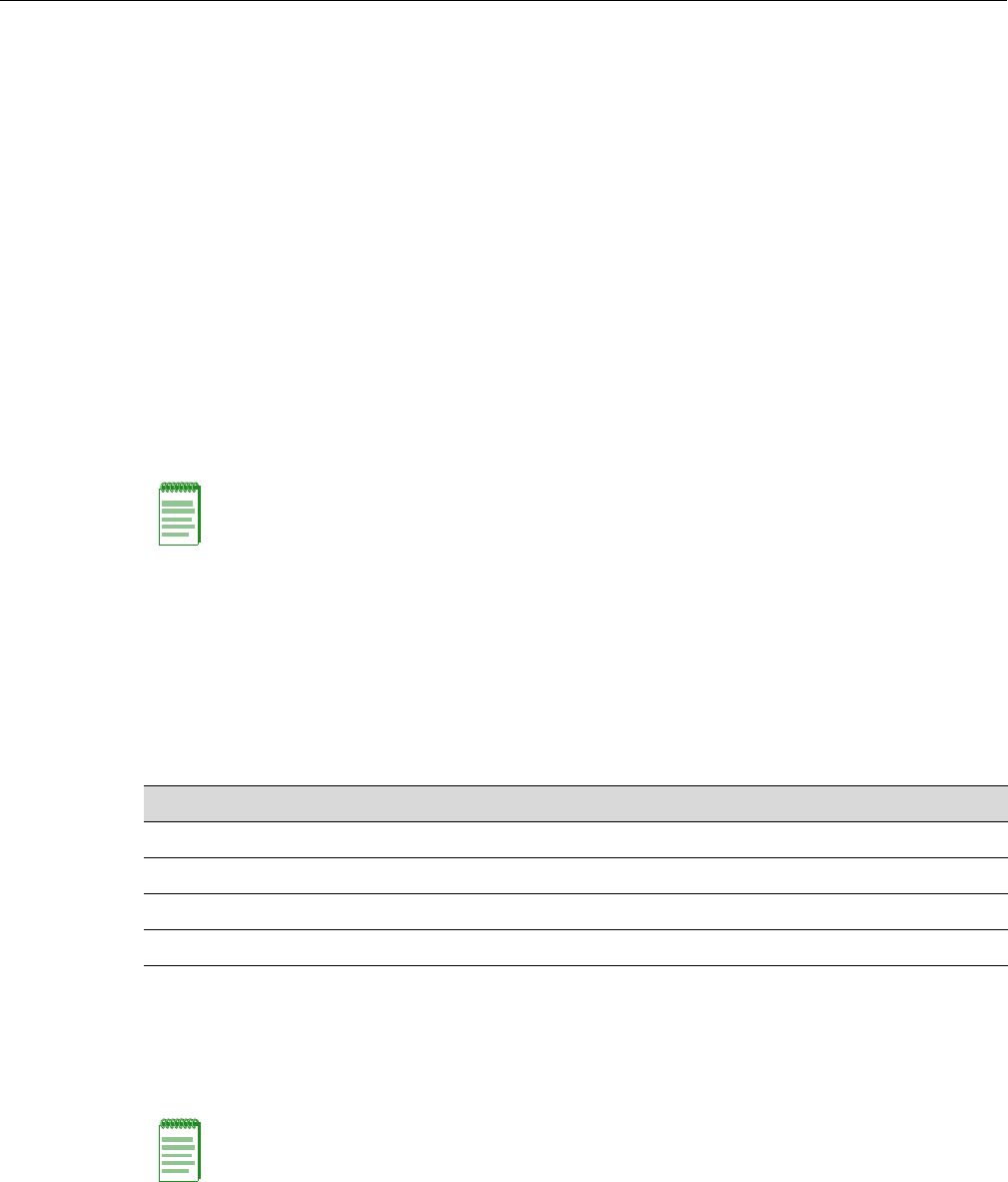
3-2 Configuring the Wireless AP
Deploying a Wireless AP with External Antennas
SomeWirelessAPmodelssupportexternalantennas.Theexternalantennasareindividually
certifiedanddeterminetheavailablechannellistandthemaximumtransmittingpowerforthe
countryinwhichtheWirelessAPisdeployed.Foralistoftheexternalantennasthatcanbeused
witheachantennamodelandhowtoinstallthem,refertotheEnterasysWirelessExternalAntenna
SitePreparationandInstallationGuide.
ThefollowingWirelessAPmodelssupportexternalantennas:
•AP2620—anEnterasysStandardWirelessAPmodel.
•AP2660—anEnterasysWirelessOutdoorAPmodel.
•AP3620—anEnterasysWireless802.11nAPmodel.
•AP3640—anEnterasysWirelessStandaloneAPmodel.
•AP3660—anEnterasysWireless802.11nOutdoorAPmodel.
•W78xC—anEnterasysWireless802.11nOutdoorAPmodel.
ConfiguretheWirelessAPtoindicatewhichexternalantennaisconnectedateachantennaport.
DeployingaWirelessAPwithexternalantennasispartoftheWirelessAPconfigurationprocess.
Formoreinformation,see“ConfiguringWirelessAPSettings”onpage 3‐29.
Enterasys Standard Wireless AP
TheEnterasysStandardWirelessAPisavailableinthefollowingmodels:
Eachmodelhastworadios—Radio1andRadio2.Figure 3‐1showsablockdiagramofthe
EnterasysStandardWirelessAPequippedwithexternalantennas.
Enterasys Standard Wireless AP Radios
TheEnterasysStandardWirelessAPisequippedwithtworadios—Radio1andRadio2.
•Radio1supportsthe5GHzradio,withradiomodea.
•Radio2supportsthe2.4GHzradio,withradiomodesb,g,andb/g.
Radio1andRadio2areconnectedtobothexternalantennas—EA1andEA2.
Note: An individual Enterasys Wireless AP cannot support an indoor mounted antenna and an
outdoor mounted antenna simultaneously. The AP4102/4102C, however, can support both indoor
and outdoor antennas simultaneously.
Table 3-1 Enterasys Standard Wireless AP Models
AP Model Description
AP2610 Internal antenna, internal dual (multimode) diversity antennas
AP2620 External antenna (dual external antennas), RP-SMA connectors
AP2605 Two external, non-detachable antennas
AP4012/4102C Integrated and external antenna
Note: The following access point radio discussion does not apply to the AP4102/4102C access
points. For more information on the AP4102/4102C access points, see “AP4102/4102C Access
Points” on page 3-4.
DRAFT
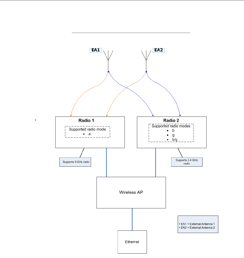
User Guide, V8.01 3-3
ThefollowingisablockdiagramoftheEnterasysStandardWirelessAPequippedwithexternal
antennas.
Figure 3-1 Enterasys Standard Wireless APs Baseband
Figure 3‐1illustratesthefollowing:
•TheEnterasysStandardWirelessAPhastworadios—Radio1andRadio2.
•Radio1supportsthe5GHzradio,withradiomodea.
•Radio2supportsthe2.4GHzradio,withradiomodesb,g,andb/g.
•Radio1andRadio2areconnectedtobothexternalantennas—EA1andEA2.
5GHzradiosupportingthe802.11astandard—The802.11astandardisanextensionto802.11
thatappliestowirelessLANsandprovidesupto54Mbpsinthe5‐GHzband.The802.11a
standardusesanorthogonalfrequencydivisionmultiplexingencodingscheme,ratherthan
Frequency‐HoppingSpreadSpectrum(FHSS)orDirect‐SequenceSpreadSpectrum(DSSS).
DRAFT

3-4 Configuring the Wireless AP
2.4GHzradiosupportingthe802.11b/gstandards—The802.11gstandardappliestowireless
LANsandspecifiesatransmissionrateof54Mbps.The802.11b(HighRate)standardisan
extensionto802.11thatspecifiesatransmissionrateof11Mbps.Since802.11gusesthesame
communicationfrequencyrangeas802.11b(2.4GHz),802.11gdevicescanco‐existwith802.11b
devicesonthesamenetwork.
TheradiosareenabledordisabledthroughtheEnterasysWirelessController.Bothradioscanbe
enabledtoofferservicesimultaneously.Formoreinformation,see“ModifyingWirelessAP2610/
2620RadioProperties”onpage 3‐52.
TheUnlicensedNationalInformationInfrastructure(U‐NII)bandsallliewithinthe5‐GHzband,
designedforshort‐range,high‐speed,wirelessnetworkingcommunication.
TheWirelessAPsupportsthefullrangeof802.11a:
•5.15to5.25GHz—U‐NIILowBand
•5.25to5.35GHz—U‐NIIMiddleBand
•5.47to5.725GHz—UNII2+
•5.725to5.825GHz—U‐NIIHighBand
AP4102/4102C Access Points
TheAP4102andAP4102CaccesspointsareEnterasysmanufacturedaccesspointsthatrun
EnterasysWLANsoftware.TheAP4102/4102Caccesspointhas2integrateddual‐bandantennas.
Diversity,whichistheuseoftwoantennastoincreasetheoddsthatabetterradiostreamis
receivedoneitheroftheantennas,issupportedonlywithintegratedantennas.
TheavailableexternalantennasfortheAP4102/4102CaccesspointarelistedinTable 3‐2.
Theantennaselectionautomaticallyrestrictschannelsandrespectivepowersettingsaccordingto
certifications.
Enterasys Wireless Outdoor APs
TheEnterasysWirelessOutdoorAPenablesyoutoextendyourWirelessLANbeyondthe
confinesofindoorlocations.TheEnterasysWirelessOutdoorAPisresistanttoharshoutdoor
conditionsandextremetemperatures.Usingtheadvancedwirelessdistributionfeatureofthe
EnterasysWirelessLAN,theEnterasysWirelessOutdoorAPcanextendyourWirelessLANto
outdoorlocationswithoutEthernetcabling.Amountingbracketisavailabletoenablequickand
easymountingoftheEnterasysWirelessOutdoorAPstowalls,rails,andpoles.
TheEnterasysWirelessOutdoorAPsupports802.11a,802.11g,802.11n(AP3660only),andfull
backwardcompatibilitywithlegacy802.11bdevices.
Table 3-2 Available Antennas for the AP4102/4102C
Left Antennas Right Antennas
RBT4K - AG - IA, 2 dBi RBT4K - AG - IA, 4 dBi
RBTES - BG - M08M, 8dBi RBTES - AH - M10M, 110 dBi
RBTES - BG - P18M, 18 dBi RBTES - AH - P23M, 23 dBi
RBTES - BG - S1490M, 14 dBi RBTES - AM - M10M, 10 dBi
RBTES - AW - S1590M, 15 dBi 90 Deg
RBTES - AW - S1590M, 16 dBi 60 Deg
DRAFT

User Guide, V8.01 3-5
TheEnterasysWirelessOutdoorAPisavailableinthreemodels:
•AP2650—Internalantenna,internaldual(multimode)diversityantennas
•AP2660—Externalantenna(dualexternalantennas),RP‐SMAconnectors
•AP3660—Externalantenna(dualexternalantennas),RP‐SMAconnectors
Enterasys Wireless 802.11n AP
TheEnterasysWireless802.11nAPdeliverstotaldataratesofupto300Mbps,dependingonits
configuration.Theimprovedthroughputof300Mbpsisspreadoveranumberofsimultaneous
userssothattheWireless802.11nAPprovides300mobileuserswithanexperiencesimilartothat
ofawired100MbpsEthernetconnection—thestandardfordesktopconnectivity.
ToconfiguretheEnterasysWireless802.11nAPtoachievethishighlinkrate,see“AchievingHigh
ThroughputwiththeWireless802.11nAP”onpage 3‐50.
MIMO
Themainstayof802.11APisMIMO(multipleinput,multipleoutput)—atechnologythatuses
advancedsignalprocessingwithmultipleantennastoimprovethethroughput.MIMOtakes
advantageofmultipathpropagationtodecreasepacketretriestoimprovethefidelityofthe
wirelessnetwork.
The802.11nAP’sMIMOradiosendsoutoneortworadiosignalsthroughitsthreeantennas.Each
ofthesesignalsiscalledaspatialstream.Becausethelocationoftheantennasonthe802.11nAPis
spacedout,eachspatialstreamfollowsaslightlydifferentpathtotheclientdevice.Furthermore,
thetwospatialstreamsgetmultipliedintoseveralstreamsastheybounceofftheobstructionsin
thevicinity.Thisphenomenoniscalledmultipath.Sincethesestreamsarebouncedfromdifferent
surfaces,theyfollowdifferentpathstotheclientdevice.Theclientdevice,whichisalso802.11n
compliant,alsohasmultipleantennas.Eachoftheantennasindependentlydecodesthearriving
signal.Theneachantenna’sdecodedsignaliscombinedwiththedecodedsignalsfromtheother
antennas.Thesoftwarealgorithmusestheredundancytoextractoneortwospatialstreamsand
enhancesthestreamsʹsignaltonoiseratio.
Theclientdevicetoosendsoutoneortwospatialstreamsthroughitsmultipleantennas.These
spatialstreamsgetmultipliedintoseveralsteamsastheybounceofftheobstructionsinthe
vicinityenroutetothe802.11nAP.The802.11nAPʹsMIMOreceiverreceivesthesemultiple
streamswiththreeantennas.Eachofthethreeantennasindependentlydecodesthearriving
signal.Theneachantennasʹsdecodedsignaliscombinedwiththedecodedsignalsfromtheother
antennas.The802.11nAPʹsMIMOreceiveragainusestheredundancytoextractoneortwo
spatialstreamsandenhancesthestreamsʹsignaltonoiseratio.
Byusingthemultiplestreams,MIMOdoublesthethroughput.
Note: Any Outdoor AP model number in the Hardware Version box on the AP Properties tab that
ends with -1 is an Outdoor AP that contains the new radio card. For example, the Enterasys
Wireless AP2650-1 Internal.
Note: The Wireless 802.11n AP is backward-compatible with existing
802.11a/b/g networks.
DRAFT
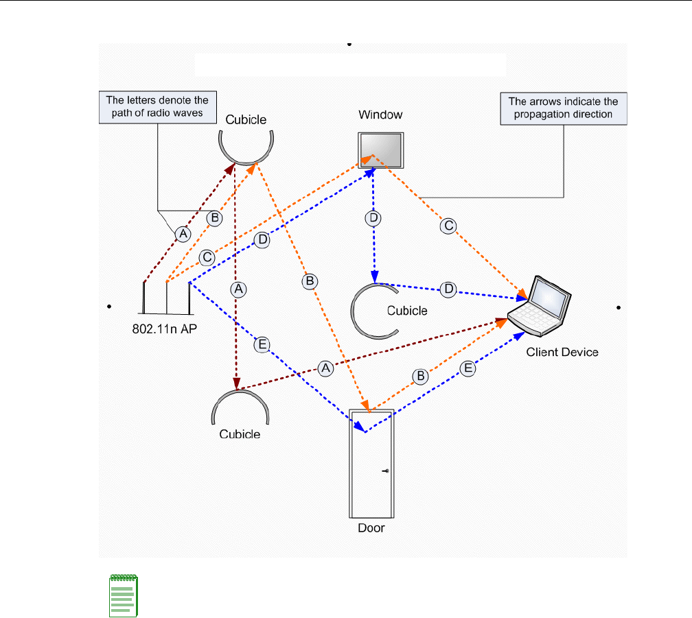
3-6 Configuring the Wireless AP
Figure 3-2 MIMO in Enterasys Wireless 802.11n AP
Becausethe802.11nAPoperateswithmultipleantennas,itiscapableofpickingupeventhe
weakestsignalsfromtheclientdevices.
Channel Bonding
InadditiontoMIMOtechnology,the802.11nAPmakesanumberofadditionalchangestothe
radiotoincreasetheeffectivethroughputoftheWirelessLAN.TheradiosofregularEnterasys
WirelessAPsuseradiochannelsthatare20MHzwide.Thismeansthatthechannelsmustbe
spacedat20MHztoavoidinterference.Theradiosof802.11nAPcanusetwochannelsatthe
sametimetocreatea40MHzwidechannel.Byusingthetwo20MHzchannelsinthismanner,the
802.11nAPachievesmorethandoublethethroughput.The40‐MHzchannelsin802.11naretwo
adjacent20‐MHzchannels,bondedtogether.Thistechniqueofusingtwochannelsatthesame
timeiscalledchannelbonding.
Note: MIMO should not be confused with the Diversity feature. While Diversity is the use of two
antennas to increase the odds that a better radio stream is received on either of the antennas,
MIMO antennas radiate and receive multi-streams of the same packet to achieve the increased
throughput.
The Diversity feature is meant to offset the liability of RF corruption, arising out of multipath,
whereas MIMO converts the liability of multipath to its advantage.
DRAFT

User Guide, V8.01 3-7
Shortened Guard Interval
Thepurposeoftheguardintervalistointroduceimmunitytopropagationdelays,echoesand
reflectionsofsymbolsinorthogonalfrequencydivisionmultiplexing(OFDM)—amethodby
whichinformationistransmittedviaaradiosignalinWirelessAPs.
InOFDM,thebeginningofeachsymbolisprecededbyaguardinterval.Aslongastheechoesfall
withinthisinterval,theywillnotaffectthesafedecodingoftheactualdata,asdataareonly
interpretedoutsidetheguardinterval.Longerguardperiodsreducethechannelefficiency.The
802.11nAPprovidesreducedguardperiods,therebyincreasingthethroughput.
MAC Enhancements
The802.11nAPalsohasanimprovedMAClayerprotocolthatreducesoverhead(intheMAC
layerprotocol)andcontentionlosses.Thisresultsinincreasedthroughput.
Models
TheWireless802.11nAPisavailableinthefollowingmodels:
•ModelAP3605—Threeinternalantennas
•ModelAP3610—Threeinternalantennas
•ModelAP3620—Threeexternalantennas
•ModelAP3630—Threeinternalantennas
•ModelAP3640—Threeexternalantennas
•ModelAP3660—Sixexternalantennas
Environment
WiththeexceptionoftheAP3660,Wireless802.11nAPscannotbedeployedinanoutdoor
environment.
Enterasys Wireless 802.11n AP’s Radios
TheEnterasysWireless802.11nAPisequippedwithtworadios—Radio1andRadio2.The
followingisablockdiagramoftheEnterasysWireless802.11nAPequippedwithexternal
antennas.
DRAFT
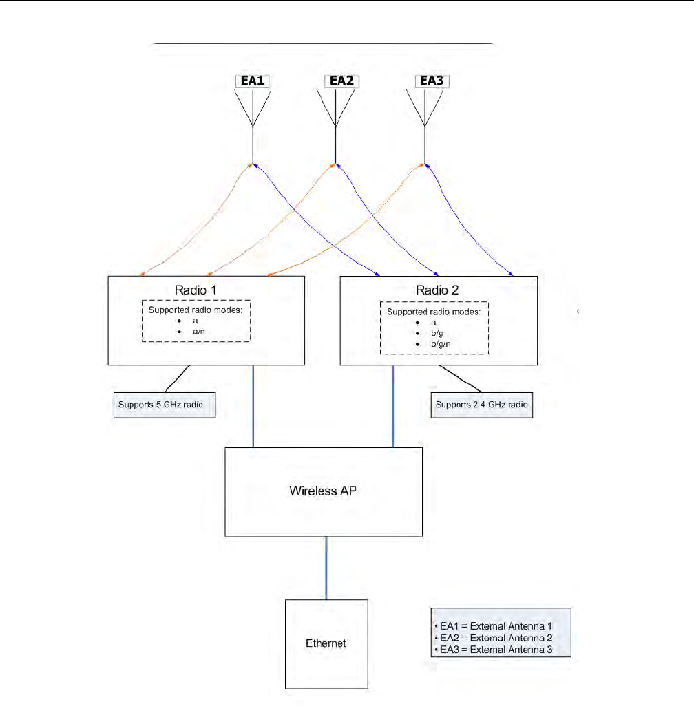
3-8 Configuring the Wireless AP
Figure 3-3 Enterasys Wireless 802.11n AP’s Baseband
Figure 3‐3illustratesthefollowing:
•TheEnterasysWireless802.11nAPhastworadios—Radio1andRadio2.
•Radio1supportsthe5GHzradio,withradiomodesa,a/n,andn‐strict.
•Radio2supportsthe2.4GHzradio,withradiomodesb,g,b/g,b/n,b/g/n,andn‐strict.
•Radio1andRadio2areconnectedtoallthreeantennas—EA1,EA2,andEA3
5GHzradiosupportingthe802.11a/nstandard—Wheninlegacy802.11amode,theAP36xx
supportsdataratesupto54Mbps,identicaltotheAP26xx.ThemodulationusedisOFDM.In
802.11nmodetherearetwosupportedchannelbandwidths,20MHzand40MHz.The802.11nAP
supportsupto300Mbpsin40MHzchannelsand130Mbpsin20MHzchannels.Themodulation
usedisMIMO‐OFDMwithoneortwospatialstreams.
DRAFT

User Guide, V8.01 3-9
2.4GHzradiosupportingthe802.11b/g/nstandard—Wheninlegacy802.11b/gmode,the
AP36xxAPssupportdataratesupto54Mbps,identicaltotheAP26xxAPs.Themodulationused
isOFDMfor11gandCCKfor11b.In802.11nmodetherearetwosupportedchannelbandwidths,
20MHzand40MHz.TheAP36xxAPssupportupto300Mbpsin40MHzchannelsand130Mbpsin
20MHzchannels.ThemodulationusedisMIMO‐OFDMwithoneortwospatialstreams.
TheradiosareenabledordisabledthroughtheEnterasysWirelessAssistant.Formore
information,see“ModifyingWireless802.11nAP3605/3610/3620/3660/W78xCRadioProperties”
onpage 3‐38.
TheUnlicensedNationalInformationInfrastructure(U‐NII)bandsallliewithinthe5‐GHzband,
designedforshort‐range,high‐speed,wirelessnetworkingcommunication.
The802.11nAPsupportsthefullrangeoffrequenciesavailableinthe5GHzband:
• 5150to5250MHz‐U‐NIILowband
• 5250to5350MHz‐U‐NIIMiddleBand
• 5470to5700MHz‐U‐NIIWorldwide
• 5725to5825MHz‐U‐NIIHighBand
Wireless AP International Licensing
TheWirelessAPmustbeconfiguredtooperateontheappropriateradiobandinaccordancewith
theregulationsofthecountryinwhichitisbeingused.Formoreinformation,seeAppendix B.
Toconfiguretheappropriateradiobandaccordingtothecountryofoperation,usetheEnterasys
WirelessController.Formoreinformation,see“ConfiguringWirelessAPSettings”onpage 3‐29.
Wireless AP Default IP Address and First-time Configuration
TheWirelessAPsareshippedfromthefactorywithadefaultIPaddress—192.168.1.20.The
defaultIPaddresssimplifiesthefirst‐timeIPaddressconfigurationprocessforWirelessAPs.If
theWirelessAPfailsinitsdiscoveryprocess,itreturnstoitsdefaultIPaddress.ThisWirelessAP
behaviorensuresthatonlyoneWirelessAPatatimecanusethedefaultIPaddressonasubnet.
Formoreinformation,see“DiscoveryandRegistrationOverview”onpage 3‐10.
TheWirelessAPscanacquiretheirIPaddressesbyoneoftwomethods:
•DHCPassignment—WhentheWirelessAPispoweredon,itattemptstoreachtheDHCP
serveronthenetworktoacquiretheIPaddress.IftheWirelessAPissuccessfulinreachingthe
DHCPserver,theDHCPserverassignsanIPaddresstotheWirelessAP.
–IftheDHCPassignmentisnotsuccessfulinthefirst60seconds,theWirelessAPreturns
toitsdefaultIPaddress.
–TheWirelessAPwaitsfor30secondsindefaultIPaddressmodebeforeagainattempting
toacquireanIPaddressfromtheDHCPserver.
–TheprocessrepeatsitselfuntiltheDHCPassignmentissuccessful,oruntilan
administratorassignstheWirelessAPanIPaddress,usingstaticconfiguration.
Note: The Wireless 802.11n AP can achieve link rates of up to 300Mbps. To achieve this level of
high link rates, specific items need to be configured through the Enterasys Wireless Controller. For
more information, see “Achieving High Throughput with the Wireless 802.11n AP” on page 3-50.
Note: DHCP assignment is the default method for the Wireless AP configuration. DHCP
assignment is part of the discovery process. For more information, see “Discovery and Registration
Overview” on page 3-10.
DRAFT

Discovery and Registration Overview
3-10 Configuring the Wireless AP
•Staticconfiguration—YoucanassignastaticIPaddresstotheWirelessAP,usingthestatic
configurationoption.Formoreinformation,seethefollowingsection.
Assigning a Static IP Address to the Wireless AP
Dependinguponthenetworkcondition,youcanassignastaticIPaddresstotheWirelessAP
usingtheEnterasysWirelessAssistant(Controller’sGUI).Referto“SettingUptheWirelessAP
UsingStaticConfiguration”onpage 3‐61formoreinformation.
Discovery and Registration Overview
WhentheWirelessAPispoweredon,itautomaticallybeginsadiscoveryprocesstodetermineits
ownIPaddressandtheIPaddressoftheEnterasysWirelessController.Whenthediscovery
processissuccessful,theWirelessAPregisterswiththeEnterasysWirelessController.
Wireless AP Discovery
WirelessAPsdiscovertheIPaddressofaEnterasysWirelessControllerusingasequenceof
mechanismsthatallowforthepossibleservicesavailableontheenterprisenetwork.Thediscovery
processissuccessfulwhentheWirelessAPsuccessfullylocatesaEnterasysWirelessControllerto
whichitcanregister.
Ensurethattheappropriateservicesonyourenterprisenetworkarepreparedtosupportthe
discoveryprocess.Thefollowingstepssummarizethediscoveryprocess:
1. UsetheIPaddressoftheEnterasysWirelessControllertowhichtheAPlastconnected
successfully
OnceaWirelessAPhassuccessfullyregisteredwithaEnterasysWirelessController,itrecalls
thatcontrollerʹsIPaddress,andusesthataddressonsubsequentreboots.TheWirelessAP
bypassesdiscoveryandgoesstraighttoregistration.
Ifthisdiscoverymethodfails,itcyclesthroughtheremainingsteps.
2. UsethepredefinedstaticIPaddressesfortheEnterasysWirelessControllersonthenetwork
(ifconfigured).
YoucanspecifyalistofstaticIPaddressesoftheEnterasysWirelessControllersonyour
network.OntheStaticConfigurationtab,addtheaddressestotheWirelessController
SearchList.
Note: You can establish a telnet or SSH session with the Wireless AP during the time window of 30
seconds when the Wireless AP returns to its default IP address mode. If a static IP address is
assigned during this period, you must reboot the Wireless AP for the configuration to take effect.
For more information, see “Assigning a Static IP Address to the Wireless AP” on page 3-10.
Warning: Only use power supplies that are recommended by Enterasys. For example, for the
Wireless 802.11n AP use WS-PS361020-MR (AP3610/AP3620 AC Power Supply-Multi-Region).
Caution: Wireless APs configured with a static Wireless Controller Search List can only connect to
Enterasys Wireless Controllers in the list. Improperly configured Wireless APs cannot connect to a
non-existent Enterasys Wireless Controller address, and therefore cannot receive a corrected
configuration.
DRAFT

Discovery and Registration Overview
User Guide, V8.01 3-11
3. UseDynamicHostConfigurationProtocol(DHCP)Option60toquerytheDHCPserverfor
availableEnterasysWirelessControllers.TheDHCPserverwillrespondtotheWirelessAP
withOption43,whichwilllisttheavailableEnterasysWirelessControllers.
FortheDHCPservertorespondtoaWirelessAP’sOption60request,youmustconfigurethe
DHCPserverwiththevendorclassidentifier(VCI)foreachWirelessAP.Youmustalso
configuretheDHCPserverwiththeIPaddressesoftheEnterasysWirelessControllers.For
moreinformation,refertoEnterasysWirelessConvergenceSoftwareGettingStartedGuide.
4. UseaDomainNameServer(DNS)lookupforthehostnameController.domain‐name.
TheWirelessAPtriestheDNSserverifitisconfiguredinparallelwithSLPunicastandSLP
multicast.
Ifyouusethismethodfordiscovery,placeanArecordintheDNSserverfor
Controller.<domain‐name>.The<domain‐name>isoptional,butifused,ensureitislisted
withtheDHCPserver.
5. UseamulticastSLPrequesttofindSLPSAs
TheWirelessAPsendsamulticastSLPrequest,lookingforanySLPServiceAgentsproviding
theEnterasysservice.
TheWirelessAPwilltrySLPmulticastinparallelwithotherdiscoverymethods.
6. UseDHCPOption78tolocateaServiceLocationProtocol(SLP)DirectoryAgent(DA),
followedbyaunicastSLPrequesttotheDirectoryAgent.
TousetheDHCPandunicastSLPdiscoverymethod,youmustensurethattheDHCPserver
onyournetworksupportsOption78(DHCPforSLPRFC2610).TheWirelessAPsusethis
methodtodiscovertheEnterasysWirelessController.
Thissolutiontakesadvantageoftwoservicesthatarepresentonmostnetworks:
–DHCP—ThestandardisameansofprovidingIPaddressesdynamicallytodevicesona
network.
–SLP—Ameansofallowingclientapplicationstodiscovernetworkserviceswithout
knowingtheirlocationbeforehand.DevicesadvertisetheirservicesusingaServiceAgent
(SA).Inlargerinstallations,aDirectoryAgent(DA)collectsinformationfromSAsand
createsacentralrepository(SLPRFC2608).
TheEnterasysWirelessControllercontainsanSLPSAthat,whenstarted,queriestheDHCP
serverforOption78andiffound,registersitselfwiththeDAasservicetypeEnterasys.The
EnterasysWirelessControllercontainsaDA(SLPD).
TheWirelessAPqueriesDHCPserversforOption78tolocateanyDAs.TheWirelessAPs’
SLPUserAgentthenqueriestheDAsforalistofEnterasysSAs.
Option78mustbesetforthesubnetsconnectedtotheportsoftheEnterasysWireless
ControllerandthesubnetsconnectedtotheWirelessAPs.Thesesubnetsmustcontainan
identicallistofDAIPaddresses.
Registration After Discovery
Anyofthediscoverysteps2through6caninformtheWirelessAPofalistofmultipleIP
addressestowhichtheWirelessAPmayattempttoconnect.OncetheWirelessAPhasdiscovered
theseaddresses,itsendsoutconnectionrequeststoeachofthem.Theserequestsaresent
simultaneously.TheWirelessAPwillattempttoregisteronlywiththefirstwhichrespondstoits
request.
DRAFT
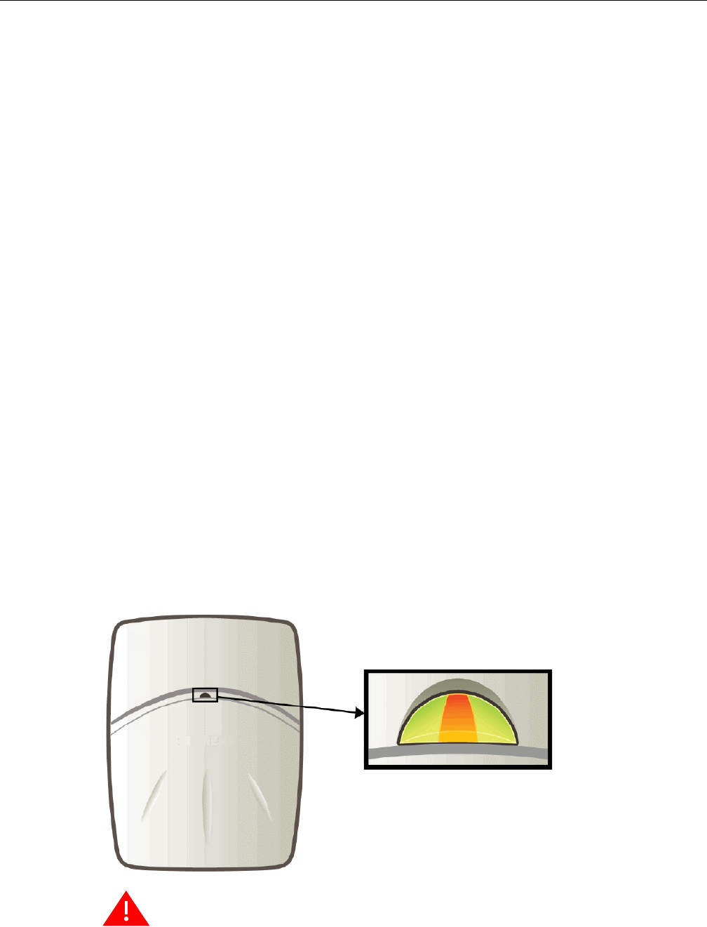
Discovery and Registration Overview
3-12 Configuring the Wireless AP
WhentheWirelessAPobtainstheIPaddressoftheEnterasysWirelessController,itconnectsand
registers,sendingitsserialnumberidentifiertotheEnterasysWirelessController,andreceiving
fromtheEnterasysWirelessControlleraportIPaddressandbindingkey.
OncetheWirelessAPisregisteredwithaEnterasysWirelessController,youmustconfigurethe
WirelessAP.AftertheWirelessAPisregisteredandconfigured,youcanassignittooneormore
VirtualNetworkServices(VNS)tohandlewirelesstraffic.
Default Wireless AP Configuration
DefaultWirelessAPconfigurationactsasaconfigurationtemplatethatcanbeautomatically
assignedtonewregisteringWirelessAPs.ThedefaultWirelessAPconfigurationallowsyouto
specifycommonsetsofradioconfigurationparametersandVNSassignmentsforWirelessAPs.
Formoreinformation,see“ConfiguringtheDefaultWirelessAPSettings”onpage 3‐76.
Understanding the Wireless AP LED Status
WhenyoupoweronandboottheWirelessAP,youcanfollowitsprogressthroughthe
registrationprocessbyobservingtheLEDsequenceasdescribedinthefollowingsections:
•EnterasysWirelessAPLEDStatus
•EnterasysWirelessOutdoorAP3660LEDIndicators
•EnterasysWirelessOutdoorAP2660LEDStatus
•EnterasysWireless802.11nAPLEDStatus
•AP4102andAP2605LEDStatus
AfteryoupoweronandboottheWirelessAPforthefirsttime,youcanconfigureLEDbehavioras
describedinConfiguringWirelessAPLEDBehavior.
Enterasys Wireless AP LED Status
ThefollowingfiguredepictsthelocationofthethreeLEDsontheEnterasysWirelessAP.
Figure 3-4 Enterasys Wireless AP LEDs
Warning: Never disconnect a Wireless AP from its power supply during a firmware upgrade.
Disconnecting a Wireless AP from its power supply during a firmware upgrade may cause firmware
corruption rendering the AP unusable.
Left LED
2.4 GHz
radio activity
Right LED
5 GHz radio
activity
Status
LED
DRAFT

Discovery and Registration Overview
User Guide, V8.01 3-13
LED Color Codes
TheAPLEDsindicate“normal‐operation”,“warning/special”,or“failed”stateoftheWirelessAP
inthefollowingcolorcodes:
•Green—Indicatesthenormal‐operationstate.
•Orange/Amber—Indicatesthewarning,orspecialstatesuchasWDS.
•Red—Indicatestheerrorstate.
•Blinking—Indicatesthatthestate,suchasinitialization,ordiscoveryisinprogress.
•Stea
dy—Indicatesthatthestateisstable/completed.Forexample,initializationfinished,or
discoverycompleted.
Center LED
TheCenterLEDindicatesthegeneralstatusoftheWirelessAP:
Left LED
TheLeftLEDindicatesthehigh‐levelstateoftheWirelessAPduringtheinitializationand
discoveryprocess:
Left and Right LEDs
TheRightLEDindicatesthedetailedstateduringtheinitializationanddiscoveryprocesses:
Table 3-3 Center LED and Wireless AP’s Status
Center LED Enterasys Wireless AP’s status
Blinking Green Initialization and discovery in progress via Ethernet link
Blinking Orange/Amber Initialization and discovery in progress via WDS link
Blinking Red Error during initialization/discovery process
Solid Red Irrecoverable error
Solid Green Discovery finished via Ethernet link
Solid Orange/Amber Discovery finished via WDS link
Table 3-4 Left LED and Wireless AP’s High-level State
Left LED Enterasys Wireless AP’s high-level state
Off Initialization
Blinking Green Network Discovery
Solid Green Connecting with the Enterasys Wireless Controller
Table 3-5 Left and Right LEDs and Wireless AP’s Detailed State
Left LED Right LED Enterasys Wireless AP’s detailed state
Off Off Initialization: Power-on self-test (POST)
Blinking Green Initialization: Random delay
Solid Green Initialization: Vulnerable period
DRAFT

Discovery and Registration Overview
3-14 Configuring the Wireless AP
Composite View of the Three LEDs
TheCenter,LeftandtheRightLEDsworkinconjunctiontoindicatethegeneral,high‐levelstate
andthedetailedstaterespectively.
Table 3‐6providesacompositeviewofthethreeLEDlightsoftheWirelessAP’sstate:
Blinking Green Off Network Discovery: 802.1x authentication
Blinking Green Network Discovery: Attempting to obtain IP address via
DHCP
Solid Green Network Discovery: Discovered Enterasys Wireless
Controller
Solid Green Off Connecting to Enterasys Wireless Controller: Attempting
to register with the Enterasys Wireless Controller
Blinking Green Connecting to Enterasys Wireless Controller: Upgrading
to higher version
Solid Green Connecting to Enterasys Wireless Controller: Configuring
itself
Table 3-6 Composite View of Three LED Lights
Left LED Right LED Center LED Enterasys Wireless AP’s Detailed state
Off Off Blinking Green Initialization: Power-on self-test (POST)
Blinking Green Blinking Green Initialization: Random delay
Blinking Red Initialization: Neither Ethernet nor WDS
link
Solid Green Blinking Green Initialization: Vulnerable period
Blinking Red Reset to factory defaults
Blinking Orange WDS scanning
Blinking Green Off Blinking Green/
Orange
Network discovery: 802.1x authentication
Blinking Red Failed 802.1x authentication
Blinking Green Blinking Green/
Orange
Network discovery: DHCP
Blinking Red Default IP address
Solid Green Blinking Green/
Orange
Network discovery: HWC discovery /
connect
Blinking Red Discovery failed
Table 3-5 Left and Right LEDs and Wireless AP’s Detailed State (continued)
Left LED Right LED Enterasys Wireless AP’s detailed state
DRAFT
Discovery and Registration Overview
User Guide, V8.01 3-15
LEDs Indicating WDS Strength for AP2610 and AP2620
TheAPindicatestheWDSsignalstrengthasabargraph.ToavoidconfusionwithstartupLED
behavior,thepatternsgofromrighttoleftandanLEDisalwaysblinkingatleasttwiceasfastas
theLEDsinnormalmode.
Table 3‐7illustratesthebehaviorofthethreeLEDlightsoftheWirelessAP’sWDSstrength.
Enterasys Wireless Outdoor AP3660 LED Indicators
TheAP3660providesfourLEDindicators(seeFigure 3‐5).TheLEDsprovidestatusinformation
(seeTable 3‐8onpage 3‐16)onthecurrentstateoftheAP3660.
Solid Green Off Blinking Green/
Orange
Connecting with Enterasys Wireless
Controller: Registration
Blinking Red Registration failed
Blinking Green Blinking Green/
Orange
Connecting with Enterasys Wireless
Controller: Image upgrade
Solid Green/
Orange
AP operating normally: Forced image
upgrade
Blinking Red Image upgrade failed
Solid Green Blinking Green/
Orange
Connecting with Enterasys Wireless
Controller: Configuration
Blinking Red Configuration failed
Note: The Left and Right LEDs turn on after the Center LED. This allows you to distinguish easily
between the Center LED and the Left/Right LEDs.
Note: If the Center LED begins blinking RED, it indicates that the Wireless AP’s state has failed.
Note: Random delays do not occur during normal reboot. A random delay only occurs after a
vulnerable period power-down.
The Wireless AP can be reset to its factory default settings. For more information, see the
Enterasys Wireless Convergence Software Maintenance Guide.
Table 3-7 AP2610 and AP2620 LEDs Indicating Signal Strength
RSS (dBm) Left LED Middle LED Right LED
RSS < -84 Off Off Blinking green
-84 < RSS < -77 Off Off Fast Blinking green
-77 < RSS < -70 Off Blinking green Solid green
-70 < RSS < -63 Blinking green Solid green Solid green
RSS < -63 Fast Blinking green Solid green Solid green
Table 3-6 Composite View of Three LED Lights (continued)
Left LED Right LED Center LED Enterasys Wireless AP’s Detailed state
DRAFT
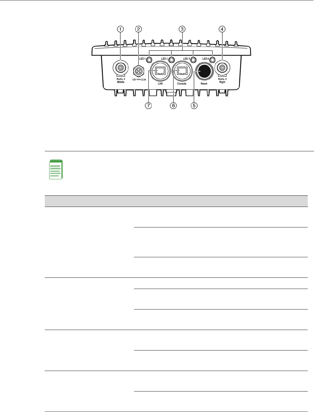
Discovery and Registration Overview
3-16 Configuring the Wireless AP
Figure 3-5 AP3660 Bottom View
1Radio 2 - Middle Antenna 5Reset Switch
212V DC Connector 6Console Port (RJ45)
3Status LEDs 7LAN Port (RJ45)
4Radio 2 - Right Antenna
Note: The AP3660 provides six external antenna ports. The network administrator determines
which antenna port will be used based on the external antenna selected. The AP3660 can also be
configured to select the antenna that provides the best possible data transmission (diversity).
Table 3-8 AP3660 LED Status Indicators
LED Status Description
1 (Power) On Green Indicates the AP3660 is working
normally.
Flashing Green Indicates:
• running a self test
• loading software program
On Red Indicates a CPU or system failure.
2 (Ethernet Link) On Blue Indicates a valid 1Gbps Ethernet link.
On Green Indicates a valid 100Mbps Ethernet link.
On Red Indicates a valid 10Mbps Ethernet link.
3 (Wireless Link) On Green Indicates Radio 1 (5GHz) is enabled.
Flashing Green Indicates the AP3660 is transmitting or
receiving data.
4 (Wireless Link) On Green Indicates Radio 2 (2.4GHz) is enabled.
Flashing Green Indicates the AP3660 is transmitting or
receiving data.
DRAFT
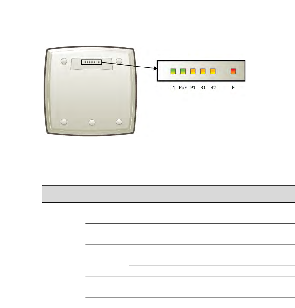
Discovery and Registration Overview
User Guide, V8.01 3-17
Enterasys Wireless Outdoor AP2660 LED Status
ThefollowingfiguredepictsthelocationoftheLEDsontheEnterasysWirelessOutdoorAP.
Figure 3-6 Enterasys Wireless Outdoor AP LEDs
TheR1,R2andFLEDsworkinconjunctiontoindicatethegeneral,high‐levelanddetailedstate
respectively.TheremainingLEDsindicatelinkstatus.
Table 3‐9providesacompositeviewoftheR1,R2andFLEDs:
Table 3-9 Enterasys Wireless Outdoor AP LED Status
R1 LED R2 LED F LED Enterasys Wireless Outdoor AP’s detailed
status
Off Off Blinking Red Initialization: Power-on-self test (POST)
Blinking Green Blinking Red Initialization: Random delay
Solid Green Blinking Red Initialization: Vulnerable Period
Solid Red Reset to factory defaults
Solid Green Blinking Red WDS scanning
Blinking Green/
Yellow
Off Blinking Red Network discovery: 802.1x authentication
Solid Red Failed 802.1x authentication
Blinking Green/
Yellow
Blinking Red Network discovery: DHCP
Solid Red Default IP address
Solid Green/
Yellow
Blinking Red Network discovery: HWC discovery/connect
Solid Red Discovery failed
DRAFT
Discovery and Registration Overview
3-18 Configuring the Wireless AP
LEDS Indicating WDS Strength for AP2650 and AP2660
TheAPindicatestheWDSsignalstrengthasabargraph.ToavoidconfusionwithstartupLED
behavior,thepatternsgofromrighttoleftandanLEDisalwaysblinkingatleasttwiceasfastas
theLEDsinnormalmode.
Table 3‐10illustratesthebehavioroftheLEDinWDSSignalStrengthforAPmodelsAP2650and
AP2660.
Solid Green Off Blinking Red Connecting with HWC: Registration
Solid Red Registration failed
Blinking Green/
Yellow
Blinking Red Connecting with HWC: Image upgrade
Solid Red Image upgrade failed
Solid Green/
Yellow
Blinking Red Connecting with HWC: Configuration
Solid Red Configuration failed
Blinking Green/
Yellow
Off AP operating and running normally: Forced
image upgrade
Solid Red Image upgrade failed
Note: After discovery is finished, the Left and Right LEDs will be Green for Ethernet uplink, and
Yellow for WDS uplink.
Note: If a fatal AP error occurs, the Status LED will be solid Red.
Table 3-9 Enterasys Wireless Outdoor AP LED Status (continued)
R1 LED R2 LED F LED Enterasys Wireless Outdoor AP’s detailed
status
Table 3-10 AP2650 and AP2660 LEDs Indicating Signal Strength
RSS (dBm) LED
L1 PoE P1 R1 R2 F
RSS < -84 Off Off Off Off Off Blinking green
-84 < RSS < -77 Off Off Off Off Off Fast Blinking
green
-77 < RSS < -70 Off Off Off Off Blinking green Solid green
-70 < RSS < -63 Off Off Off Blinking green Solid green Solid green
-63 < RSS < -56 Off Off Blinking green Solid green Solid green Solid green
-56 < RSS < -49 Off Blinking
green
Solid green Solid green Solid green Solid green
-49 < RSS < -42 Blinking green Solid green Solid green Solid green Solid green Solid green
RSS < -42 Fast Blinking
green
Solid green Solid green Solid green Solid green Solid green
DRAFT
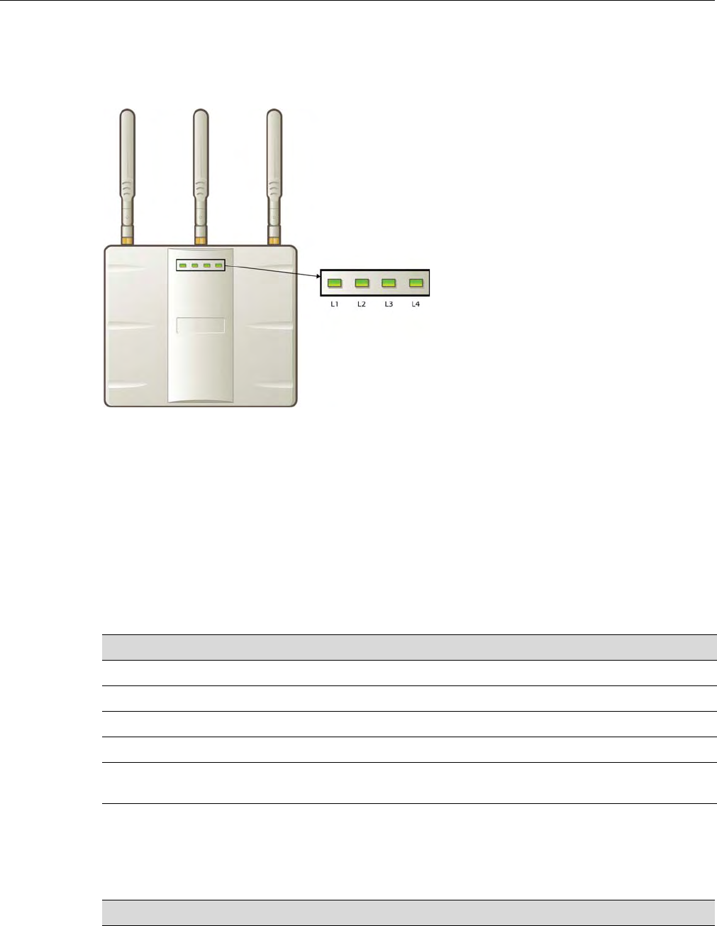
Discovery and Registration Overview
User Guide, V8.01 3-19
Enterasys Wireless 802.11n AP LED Status
Figure 3‐7depictsthelocationoftheLEDsontheEnterasysWireless802.11n.
Figure 3-7 Enterasys Wireless 802.11n AP LEDs
LEDsL1,L3,andL4workinconjunctiontoindicatethegeneral,high‐level,anddetailedstate
respectively.LEDL2indicatesthestatusoftheEthernetport.
Afterinitializationanddiscoveryiscompletedandthe802.11nAPisconnectedtotheEnterasys
WirelessController,LEDsL3andL4indicatethestateofthecorrespondingradio—L3forRadio
5GHz,andL4forRadio2.4GHz.
LEDs Color Codes
The802.11nAPLEDsindicate“normal‐operation”,“warning/special”,or“failed”stateofthe
WirelessAPinthefollowingcolorcodes:
LED L1
LEDL1indicatesthegeneralstateofthe802.11nAP:
Table 3-11 LED Color Codes
LED Color/State Description
Green Normal operational state.
Orange/amber Warning or special state, such as WDS.
Blinking AP state, such as initialization or discovery, is in progress.
Red Error state
Steady color AP state is stable; process is completed. For example, initialization is
finished or discovery completed.
Table 3-12 LED L1 and Wireless AP’s Status
L1 Enterasys Wireless 802.11n AP’s general state
Blink Green Initialization and discovery in progress via Ethernet
DRAFT

Discovery and Registration Overview
3-20 Configuring the Wireless AP
LEDs L3 and L4
LEDsL3andL4indicatethedetailedstateoftheWirelessAP.LEDsL1,L3,andL4workin
conjunctiontoindicatethegeneralanddetailedstateofthe802.11nAP.
Table 3‐13providesacompositeviewofthethreeLEDsandthecorrespondingstateofthe802.11n
AP:
Blink Amber Initialization and discovery in progress via WDS
Blink Red Error during initialization and discovery
Solid Green Discovery finished via Ethernet
Solid Amber Discovery finished via WDS
Table 3-13 LEDs L3, L4 and L1, and Wireless 802.11n AP’s Detailed State
L3 L4 L1 Enterasys Wireless 802.11n AP’s detailed state
Off Off Blink Green Initialization: Power-on self test (POST)
Blink Green Blink Green
Blink Red
Solid Green Blink Green
Blink Red
Blink Amber
Blink Green Off Blink Green /
Orange
Network discovery: 802.1x authentication
Blink Red Failed 802.1x authentication
Blink Green Blink Green /
Amber
Network discovery: DHCP
Blink Red Default IP address
Solid Green Blink Green /
Amber
Network discovery: HWC discovery / connect
Blink Red Discovery failed
Solid Green Off Blink Green /
Amber
Connecting to HWC: Registration
Blink Red Registration failed
Blink Green Blink Green
Amber
Connecting to HWC: Image upgrade
Solid Green /
Amber
AP operating normally: Forced image upgrade
Blink Red Image upgrade failed
Solid Green Blink Green /
Amber
Connecting to HWC: Configuration
Blink Red Configuration failed
Table 3-12 LED L1 and Wireless AP’s Status (continued)
L1 Enterasys Wireless 802.11n AP’s general state
DRAFT
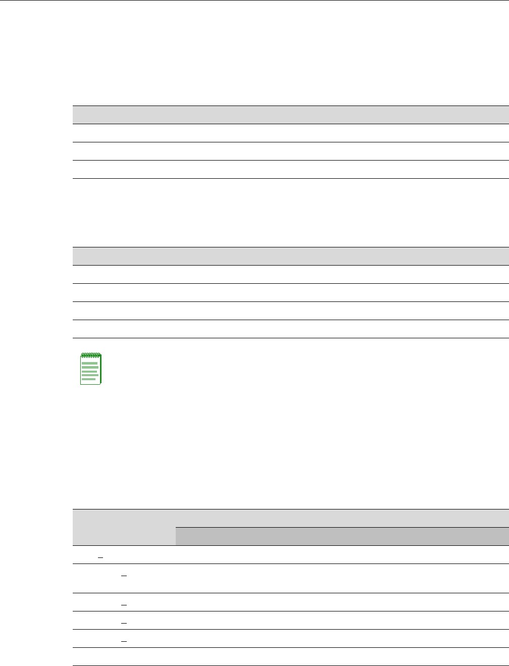
Discovery and Registration Overview
User Guide, V8.01 3-21
Afterinitializationanddiscoveryiscompletedandthe802.11nAPisconnectedtotheEnterasys
WirelessController,theLEDsL3andL4indicatethestateofthecorrespondingradio—L3for
Radio5GHz,andL4forRadio2.4GHz.
Figure 3‐14providesaviewoftheLEDsL3andL4andthecorrespondingradiostateafterthe
discoveryiscompleted.
LED L2
TheLEDL2indicatesthestatusoftheEthernetport:
LEDS Indicating WDS Strength for AP3610 and AP3620
TheAPindicatestheWDSsignalstrengthasabargraph.ToavoidconfusionwithstartupLED
behavior,thepatternsgofromrighttoleftandanLEDisalwaysblinkingatleasttwiceasfastas
theLEDsinnormalmode.
Table 3‐16illustratesthebehavioroftheLEDbehaviorinWDSSignalStrengthmodeforAP
modelsAP3610andAP3620.
Table 3-14 LEDs L3 and L4, and Corresponding Radio State
L3/L4 Radio status
Off Radio off
Solid Blue Radio in HT mode
Solid Green Radio in legacy mode
Table 3-15 LED L2 and Ethernet Port’s Status
L2 Ethernet port’s status
Off No Ethernet connection: WDS is enabled
Solid Blue 1 Gb Ethernet connection
Solid Green 100 Mb Ethernet connection
Solid Amber 10 Mb Ethernet connection
Note: A 10 Mb Ethernet connection is considered a warning state since it is not sufficient to sustain
a single radio in the legacy 11g or 11a modes.
Table 3-16 AP3610 and AP3620 LEDs Indicating Signal Strength
RSS (dBm)
LED
L1 L2 L3 L4
RSS < -84 Off Off Off Blinking green
-84 < RSS < -77 Off Off Off Fast Blinking
green
-77 < RSS < -70 Off Off Blinking green Solid green
-70 < RSS < -63 Off Blinking green Solid green Solid green
-63 < RSS < -56 Blinking green Solid green Solid green Solid green
RSS < -56 Fast Blinking green Solid green Solid green Solid green
DRAFT
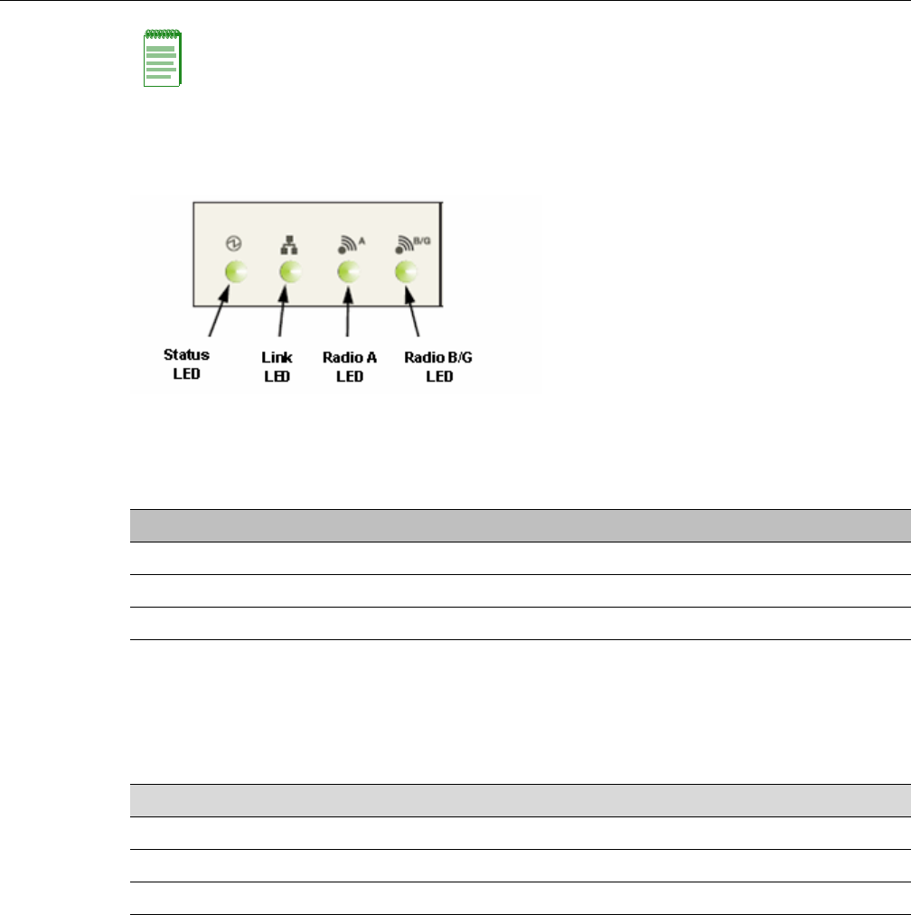
Discovery and Registration Overview
3-22 Configuring the Wireless AP
AP4102 and AP2605 LED Status
ThefollowingfigureshowstheLEDsontheAP4102andAP2605AccessPoints.
Status LED
TheStatusLEDindicatesthegeneralstatusoftheaccesspoint.
Radio B/G LED
TheRadioB/GLEDwillshowthegeneralhigh‐levelstateduringinitializationanddiscoveryfor
theaccesspoint.
Composite View of LEDs
ThefollowingtablesummarizesallLEDsduringtheinitializationanddiscovery.
ThesestateswillbeshowntogetherwithastatusLEDblinkinggreenororange.IfthestatusLED
isblinkinggreen,thestatewillbetheoneexecutedbytheAPinthatmoment.IfthestatusLEDis
blinkingorange,thestatewillbetheonethattheAPfailed.
ThestatusandradioLEDswillblinkwith1/3pulsewidth,buttheradioLEDswillturnonafter
thestatusLED.ThissolutionalsoallowstheusertodistinguisheasilybetweenthestatusLEDand
theradioLEDs.
Note: The LEDs on the AP3605 do not indicate WDS signal strength.
Table 3-17 AP4102 and AP2605 Status Indicators
Status LED AP Status
Blink green Initialization and discovery in progress via Ethernet or WDS link
Blink amber Error during initialization and discovery
Solid green Discovery finished via Ethernet or WDS link
Table 3-18 AP4102 and AP2605 Initialization and Discovery Indicators
Radio B/G LED AP High-Level State
Off Initialization
Blink green Network discovery
Solid green Connecting with Enterasys Wireless Controller
DRAFT

Discovery and Registration Overview
User Guide, V8.01 3-23
LEDs Indicating WDS Strength for AP4102 and AP2605
TheAPindicatestheWDSsignalstrengthasabargraph.ToavoidconfusionwithstartupLED
behavior,thepatternsgofromrighttoleftandanLEDisalwaysblinkingatleasttwiceasfastas
theLEDsinnormalmode.
Table 3‐20illustratestheLEDbehaviorinWDSSignalStrengthmodeforAPmodelsAP4102and
AP2605.
Table 3-19 AP4102 and AP2605 Composite View of LEDs
Radio B/G
LED Radio A
LED Status
LED AP Detailed State
Off Off Blink green Initialization: Power-on self test (POST)
Blink green Blink green Initialization: Random delay
Blink orange Initialization: No Ethernet nor WDS link
Solid green Blink green Initialization: Vulnerable period
Blink orange Reset to factory defaults
Solid green Blink green WDS scanning
Blink green Off Blink green Network discovery: 802.1x authentication
Blink orange Failed 802.1x authentication
Blink green Blink green Network discovery: DHCP
Blink orange Default IP address
Solid green Blink green Network discovery: HWC discovery /
connect
Blink orange Discovery failed
Solid Green Off Blink green Connecting with HWC: Registration
Blink orange Registration failed
Blink green Blink green Connecting with HWC: Image upgrade
Blink orange Image upgrade failed
Solid green Blink green Connecting with HWC: Configuration
Blink orange Configuration failed
Blink green Solid green AP up and running: Forced image upgrade
Blink orange Image upgrade failed
Table 3-20 AP4102 and AP2605 LEDs Indicating Signal Strength
RSS (dBm) LED
Status Link Radio A Radio B/G
RSS < -84 Off Eth state Off Blinking green
-84 < RSS < -77 Off Eth state Off Fast Blinking
green
-77 < RSS < -70 Off Eth state Blinking green Solid green
-70 < RSS < -63 Blinking green Eth state Solid green Solid green
DRAFT
Discovery and Registration Overview
3-24 Configuring the Wireless AP
Configuring Wireless AP LED Behavior
YoucanconfigurethebehavioroftheLEDssothattheyprovidethefollowinginformation:
YoucanconfiguretheAPLEDmodewhenyouconfigure:
•AnindividualWirelessAP.
•MultipleWirelessAPssimultaneously.
•DefaultWirelessAPbehavior.
To Configure the AP LED Operational Mode When Configuring an Individual
Wireless AP:
1. Fromthetopmenu,clickWirelessAPs.TheWirelessAPscreendisplays.
2. Intheleft‐handpane,clickAllAPs.TheAPConfigurationpagedisplayswiththeAP
Propertiestabexposed.
3. Inthesecondcolumnfromtheleft,selecttheappropriateAP.
4. OntheAPPropertiestab,clicktheAdvancedbutton.TheAdvancedwindowdisplays.
5. IntheLEDfield,clickthearrowandselectanLEDoperationalmode.SeeTable 3‐21fora
descriptionofeachoption.
To Set the AP LED Operational Mode When Using the AP Mulit-edit Feature:
1. Fromthetopmenu,clickWirelessAPs.TheWirelessAPwindowdisplays.
2. Intheleft‐handpane,clickAPMulti‐edit.TheAPMulti‐editwindowdisplays.
RSS < -63 Fast Blinking green Eth state Solid green Solid green
Table 3-20 AP4102 and AP2605 LEDs Indicating Signal Strength (continued)
RSS (dBm) LED
Status Link Radio A Radio B/G
Table 3-21 LED Operational Modes
LED Mode Information Displayed
Off Displays fault patterns only. LEDs do not light when the AP is fault
free and the discovery is complete.
Normal Identifies the AP status during the registration process during power
on and boot process.
Identify All LEDs blink simultaneously approximately two to four times every
second.
WDS Signal Strength Indicates the WDS signal strength as a bar graph. See Table 3-7,
Table 3-10, Table 3-16, and Table 3-20 for a description of LED
behavior.
This setting helps to align external antennas in WDS deployments by
correlating the WDS link RSS with the LED pattern. Use this setting
only if the AP operates in WDS mode by being a member of a WDS
VNS.
Note: You can configure all four AP LED modes if you configure an individual Wireless AP or
multiple Wireless APs simultaneously. If you configure the default
Wireless AP behavior, the only LED modes available are Off and Normal.
DRAFT

Discovery and Registration Overview
User Guide, V8.01 3-25
3. IntheWirelessAPsection,selectoneormoreWirelessAPs.TheAPConfigurationscreen
displays.
4. IntheAPConfigurationsection,locatetheLEDfield.ClickthearrowandselectanLED
operationalmode.SeeTable 3‐21foradescriptionofeachoption.
To Set the AP LED Operational Mode When Configuring Default AP Behavior:
1. Fromthetopmenu,clickWirelessAPs.TheWirelessAPscreenisdisplayed.
2. Intheleftpane,clickAPDefaultSettings.TheAPDefaultSettingspagedisplayswiththe
CommonConfigurationtabexposed.
3. ClicktheAPtabthatcorrespondstothetypeofAPthatyouwanttoconfigure.TheAP
PropertiesandRadiosettingsbecomeavailable.
4. ClicktheAdvancedbutton.TheAdvancedwindowdisplays.
5. IntheLEDfield,clickthearrowandselectanLEDoperationalmode.SeeTable 3‐21fora
descriptionofeachoption.
Configuring the Wireless APs for the First Time
BeforetheWirelessAPisconfiguredforthefirsttime,youmustfirstconfirmthatthefollowing
hasalreadyoccurred:
•TheEnterasysWirelessControllerhasbeensetup.Formoreinformation,seeChapter 2,
ConfiguringtheEnterasysWirelessController.
•TheEnterasysWirelessControllerhasbeenconfigured.Formoreinformation,seeChapter 2,
ConfiguringtheEnterasysWirelessController.
•TheWirelessAPshavebeeninstalled.
IfyouareinstallingtheEnterasysWirelessAP,seetheEnterasysWirelessAPInstallation
Instructions.
–IfyouareinstallingtheEnterasysWireless802.11nAP,seetheEnterasysWireless802.11n
APInstallationInstructions.
–IfyouareinstallingtheEnterasysWirelessOutdoorAP,seetheEnterasysWireless
OutdoorAPInstallationInstructionsandtheEnterasysWirelessOutdoorAPInstallation
Guide.
Oncetheinstallationsarecompleted,youcanthencontinuewiththeWirelessAPinitial
configuration.TheWirelessAPinitialconfigurationinvolvestwosteps:
1. Defineparametersforthediscoveryprocess.Formoreinformation,see“DefiningProperties
fortheDiscoveryProcess”onpage 3‐26.
2. ConnecttheWirelessAPtoapowersourcetoinitiatethediscoveryandregistrationprocess.
Formoreinformation,see“ConnectingandInitiatingtheWirelessAPDiscoveryand
RegistrationProcess”onpage 3‐28.
Adding a Wireless AP Manually Option
AnalternativetotheautomaticdiscoveryandregistrationprocessoftheWirelessAPisto
manuallyaddandregisteraWirelessAPtotheEnterasysWirelessController.Formore
information,see“AddingandRegisteringaWirelessAPManually”onpage 3‐28.
DRAFT

Discovery and Registration Overview
3-26 Configuring the Wireless AP
Defining Properties for the Discovery Process
BeforeaWirelessAPisconfigured,youmustdefinethefollowingpropertiesforthediscovery
process:
•SecurityMode
•DiscoveryTimers
ThediscoveryprocessistheprocessbywhichtheWirelessAPsdeterminetheIPaddressofthe
EnterasysWirelessController.
Security Mode
SecuritymodedefineshowtheEnterasysWirelessControllerbehaveswhenregisteringnew,
unknowndevices.Duringtheregistrationprocess,theEnterasysWirelessController’sapprovalof
theWirelessAP’sserialnumberdependsonthesecuritymodethathasbeenset:
•AllowallWirelessAPstoconnect
–IftheEnterasysWirelessControllerdoesnotrecognizetheregisteringserialnumber,a
newregistrationrecordisautomaticallycreatedfortheAP(ifwithinMDLlicenselimit).
TheAPreceivesadefaultconfiguration.Thedefaultconfigurationcanbethedefault
templateassignment.
–IftheEnterasysWirelessControllerrecognizestheserialnumber,itindicatesthatthe
registeringdeviceispre‐registeredwiththecontroller.Thecontrollerusestheexisting
registrationrecordtoauthenticatetheAPandtheexistingconfigurationrecordto
configuretheAP.
•AllowonlyapprovedWirelessAPstoconnect(thisisalsoknownassecuremode)
–IfEnterasysWirelessControllerdoesnotrecognizetheAP,theAPʹsregistrationrecordis
createdinpendingstate(ifwithinMDLlimits).Theadministratorisrequiredtomanually
approveapendingAPforittoprovideactiveservice.ThependingAPreceivesminimum
configuration,whichonlyallowsittomaintainanactivelinkwiththecontrollerforfuture
statechange.TheAPʹsradiosarenotconfiguredorenabled.PendingAPsarenoteligible
forconfigurationoperations(VNSAssignment,defaulttemplate,Radioparameters)until
approved.
–IftheEnterasysWirelessControllerrecognizestheserialnumber,thecontrollerusesthe
existingregistrationrecordtoauthenticatetheAP.Followingsuccessfulauthentication,
theAPisconfiguredaccordingtoitsstoredconfigurationrecord.
Note: During the initial setup of the network, Enterasys recommends that you select the Allow all
Wireless APs to connect option. This option is the most efficient way to get a large number of
Wireless APs registered with the Enterasys Wireless Controller.
Once the initial setup is complete, Enterasys recommends that you reset the security mode to the
Allow only approved Wireless APs to connect option. This option ensures that no unapproved
Wireless APs are allowed to connect. For more information, see “Configuring Wireless AP Settings”
on page 3-29.
DRAFT
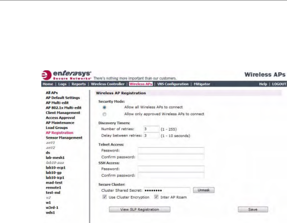
Discovery and Registration Overview
User Guide, V8.01 3-27
Discovery Timers
Thediscoverytimerparametersdictatethenumberofretryattemptsandthetimedelaybetween
eachattempt.
To Define the Discovery Process Parameters:
1. Fromthetopmenu,clickWirelessAPs.TheWirelessAPscreenisdisplayed.
2. Intheleftpane,clickAPRegistration.TheWirelessAPRegistrationscreenisdisplayed.
3. IntheSecurityModesection,selectoneofthefollowing:
–AllowallWirelessAPstoconnect
–AllowonlyapprovedWirelessAPstoconnect
TheAllowallWirelessAPstoconnectoptionisselectedbydefault.Formoreinformation,see
“SecurityMode”onpage 3‐26.
4. IntheDiscoveryTimerssection,typethediscoverytimervaluesinthefollowingboxes:
–Numberofretries
–Delaybetweenretries
Thenumberofretriesislimitedto255forthediscovery.Thedefaultnumberofretriesis3,and
thedefaultdelaybetweenretriesis3seconds.
5. Tosaveyourchanges,clickSave.
Oncethediscoveryparametersaredefined,youcanconnecttheWirelessAPtoapowersource.
DRAFT

Adding and Registering a Wireless AP Manually
3-28 Configuring the Wireless AP
Connecting and Initiating the Wireless AP Discovery and Registration
Process
WhenaWirelessAPispoweredon,itautomaticallybeginsthediscoveryandregistrationprocess
withtheEnterasysWirelessController.
Table 3‐22liststhewaysinwhichWirelessAPscanbeconnectedandpowered.
Adding and Registering a Wireless AP Manually
YoucanmanuallyaddandregisteraWirelessAPtothecontrollerinsteadofusingtheautomatic
discoveryandregistration.WhenyoumanuallyaddandregisteranAP,thesystemappliesthe
defaultsettingstotheAP.AfterthesystemregisterstheAP,youcangoinandeditits
configurationsettings.Formoreinformation,seeConfiguringWirelessAPSettings.
ToaddandregisteraWirelessAPmanually:
1. Fromthetopmenu,clickWirelessAPs.TheWirelessAPscreenisdisplayed.
Regardlessofthetabyouclickon,theAddWirelessButtondisplaysatthebottomofthepage.
2. ClicktheAddWirelessAPbutton.
Table 3-22 Connecting and Powering a Wireless AP
Wireless AP Method of Connecting and Powering
Enterasys Wireless AP • Power over Ethernet (802.3af):
– PoE enabled switch port
– PoE Injector
• Power by AC adaptor
Enterasys Wireless
Outdoor AP
• Power over Ethernet (802.3af)
– PoE enabled switch port
–PoE Injector
• Power by 48VDC (Direct Current)
• 110-230 VAC (Alternating Current)
For more information, see the Enterasys Wireless Outdoor Access Point
Installation Guide.
Enterasys Wireless
802.11n AP
• Power over Ethernet (802.3af)
– PoE enabled switch port
–PoE Injector
Note: Use a 1 GB PoE injector to ensure optimum performance of the
Enterasys Wireless 802.11n AP.
• Power by AC adaptor
DRAFT
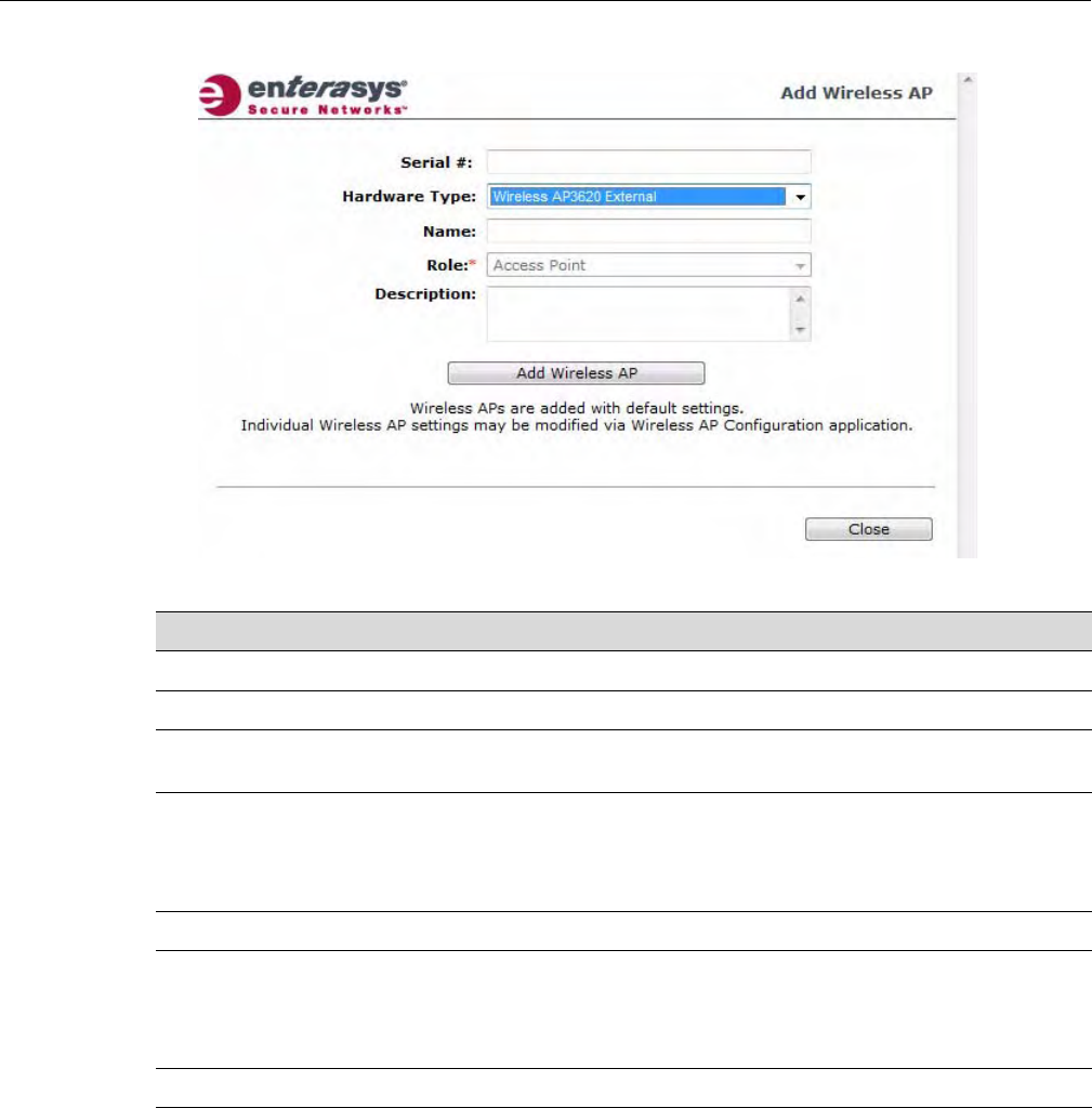
Configuring Wireless AP Settings
User Guide, V8.01 3-29
TheAddWirelessAPscreendisplays.
Configuring Wireless AP Settings
WirelessAPsareaddedwithdefaultsettings,whichyoucanadjustandconfigureaccordingto
yournetworkrequirements.Inaddition,youcanmodifythepropertiesandthesettingsforeach
radioontheWirelessAP.
YoucanalsolocateandselectWirelessAPsinspecificregistrationstatestomodifytheirsettings.
Forexample,thisfeatureisusefulwhenapprovingpendingWirelessAPswhentherearealarge
numberofotherWirelessAPsthatarealreadyregistered.OntheAccessApprovalscreen,click
PendingtoselectallpendingWirelessAPs,thenclickApprovetoapproveallselectedWireless
APs.
Table 3-23 Add Wireless AP window
Field Description
Serial # Type the Wireless AP’s unique identifier.
Hardware Type Select the hardware model of this AP from the drop-down menu
Name Type a unique name for the Wireless AP that identifies the access
point. The default value is the Wireless AP’s serial number.
Role Select the role for this AP: access point or sensor.
If the hardware type you select only supports the access point
role, the items in the drop-down list may be view-only. Not all
Wireless AP hardware types support the sensor role. .
Description Enter a description of this AP.
Add Wireless AP Click to add the Wireless AP with default settings. You can later
modify these settings.
When a Wireless AP is added manually, it is added to the
controller database only and does not get assigned.
Close Click to close this window.
DRAFT
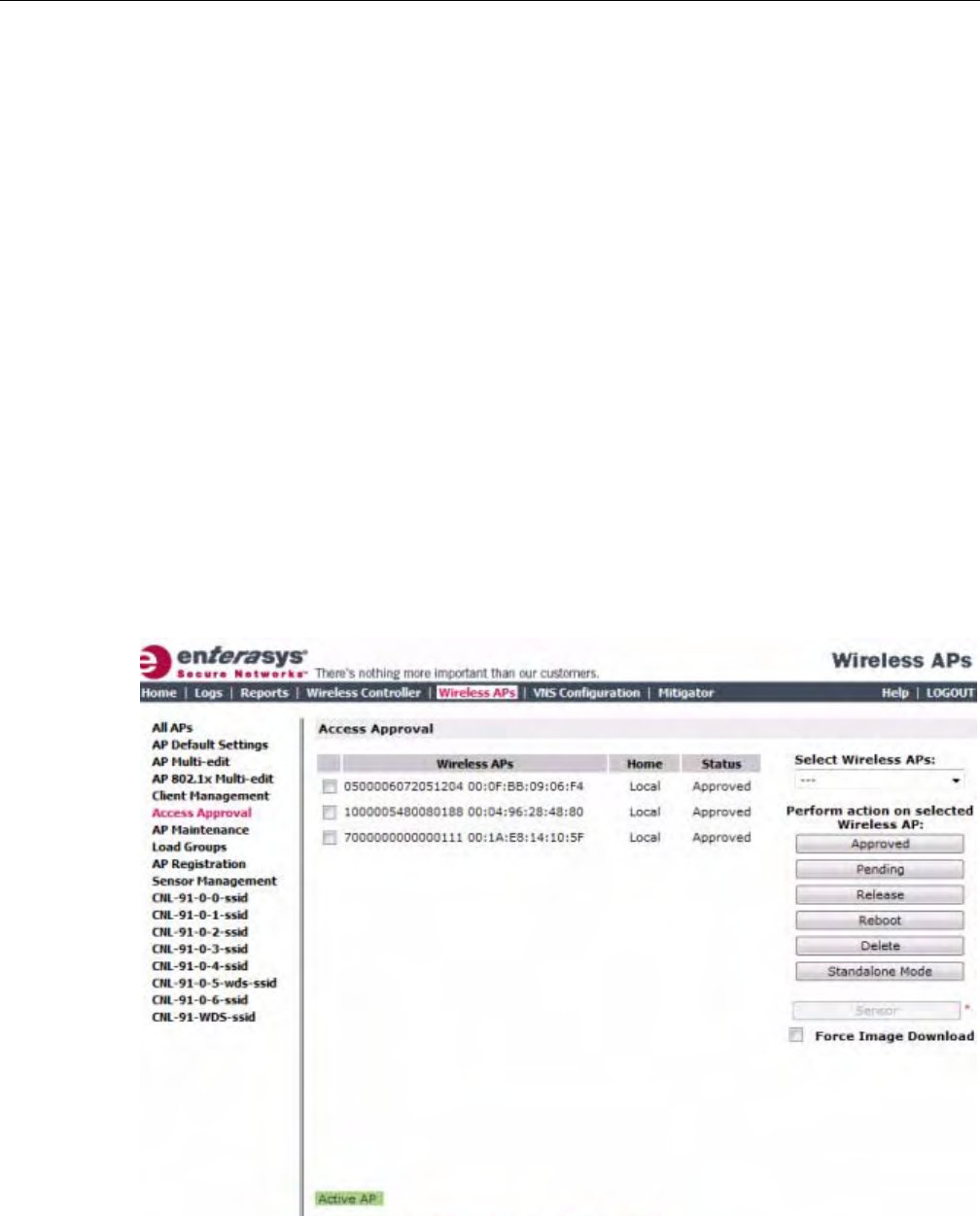
Configuring Wireless AP Settings
3-30 Configuring the Wireless AP
ConfiguringWirelessAPsettingscanincludethefollowingprocesses:
•ModifyingaWirelessAP’sStatus
•ConfiguringaWirelessAP’sProperties
•ConfiguringWirelessAPRadioProperties
•SettingUptheWirelessAPUsingStaticConfiguration
•SettingUp802.1xAuthenticationforaWirelessAP
WhenconfiguringWirelessAPs,youcanchoosetoconfigureindividualWirelessAPsor
simultaneouslyconfigureagroupofWirelessAPs.Formoreinformation,see“Configuring
MultipleWirelessAPsSimultaneously”onpage 3‐108.
Modifying a Wireless AP’s Status
Ifduringthediscoveryprocess,theEnterasysWirelessControllersecuritymodewasAllowonly
approvedWirelessAPstoconnect,thenthestatusoftheWirelessAPisPending.Youmust
modifythesecuritymodetoAllowallWirelessAPstoconnect.Formoreinformation,see
“SecurityMode”onpage 3‐26.
To Modify a Wireless AP's Registration Status:
1. Fromthetopmenu,clickWirelessAPs.TheWirelessAPscreenisdisplayed.
2. Intheleftpane,clickAccessApproval.TheAccessApprovalscreenisdisplayed,alongwith
theregisteredWirelessAPsandtheirstatus.
3. ToselecttheWirelessAPsforstatuschange,dooneofthefollowing:
–ForaspecificWirelessAP,selectthecorrespondingcheckbox.
–ForWirelessAPsbycategory,clickoneoftheSelectWirelessAPsoptions.
DRAFT

Configuring Wireless AP Settings
User Guide, V8.01 3-31
ToclearyourWirelessAPselections,clickDeselectAll.
4. ClicktheappropriatePerformactiononselectedWirelessAPsoption:
–Approved—ChangeaWirelessAPʹsstatustoApproved—aWirelessAPʹsstatus
changesfromPendingtoApprovediftheAPRegistrationscreenwasconfiguredto
registeronlyapprovedWirelessAPs.
–Pending—APisremovedfromtheActivelist,andisforcedintodiscovery.
–Release—ReleaseforeignWirelessAPsafterrecoveryfromafailover.ReleasinganAP
correspondstotheAvailabilityfunctionality.Formoreinformation,seeChapter 11,
AvailabilityandSessionAvailability.
–Reboot—ReboottheAPwithoutusingTelnetorSSHtoaccessit.
–Delete—ReleasestheWirelessAPfromtheEnterasysWirelessControlleranddeletesthe
WirelessAP’sentryintheEnterasysWirelessControllerʹsmanagementdatabase.
–StandaloneMode—The802.11nAPrunningV7.31orlaterconvertsfromfitmodeto
standalonemode.Formoreinformation,see“ConvertingtheWirelessAPtoStandalone
Mode”onpage 3‐1180.
Configuring a Wireless AP’s Properties
OnceaWirelessAPhassuccessfullyregistered,youcanthencontinuetoconfigureitsproperties.
ConfiguringWirelessAPpropertiesincludesworkingwiththefollowingWirelessAPtabs:
•APproperties
•VNSAssignment
•Radio1
•Radio2
•StaticConfiguration
• 802.1x
AP Properties Tab Configuration
UsetheAPPropertiestabtoviewandconfigurebasicWirelessAPproperties.Someofthe
WirelessAPpropertiescanbeviewedandconfiguredviatheAdvanceddialog.Thefollowing
WirelessAPpropertiesonthistabareread‐only:
•Serial#—Displaysauniqueidentifierthatisassignedduringthemanufacturingprocess.
•HostName—Thisvalue,whichisbasedonAPName,cannotbedirectlyedited.Thisvalue
depictstheAPHost‐Namevalue.IftheAPNamevaluedoesbeginwithanumber,for
examplewhenitistheAPʹsserialnumber,theAPʹsmodelisprependedtothevalue.This
valueisusedfortrackingpurposesontheDHCPserver.
•Port—DisplaystheEthernetportoftheEnterasysWirelessControllertowhichtheWireless
APisconnected.
•HardwareVersio n—DisplaysthecurrentversionoftheWirelessAPhardware.
•ApplicationVer sion—DisplaysthecurrentversionoftheWirelessAPsoftware.
•Status:
–Approved—IndicatesthattheWirelessAPhasreceiveditsbindingkeyfromthe
EnterasysWirelessControllerafterthediscoveryprocess.
DRAFT
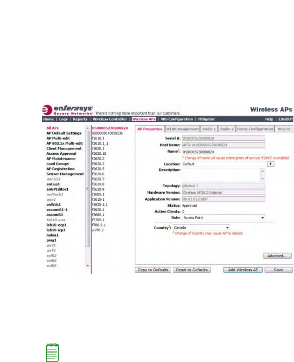
Configuring Wireless AP Settings
3-32 Configuring the Wireless AP
–Ifnostatusisshown,thatindicatesthattheWirelessAPhasnotyetsuccessfullybeen
approvedforaccesswiththesecureEnterasysWirelessController.
YoucanmodifythestatusofaWirelessAPontheAccessApprovalscreen.Formore
information,see“ModifyingaWirelessAP’sStatus”onpage 3‐30.
•ActiveClients—Displaysthenumberofwirelessdevicescurrentlyassociatedwiththe
WirelessAP.
To Modify a Wireless AP’s Properties
1. Fromthetopmenu,clickWirelessAPs.TheWirelessAPscreenisdisplayed.
2. IntheWirelessAPlist,clicktheWirelessAPwhosepropertiesyouwanttomodify.TheAP
PropertiestabdisplaysWirelessAPinformation.
3. ModifytheWirelessAP’sinformation:
–Name—TypeauniquenamefortheWirelessAPthatidentifiestheaccesspoint.The
defaultvalueistheWirelessAP’sserialnumber.
–Location—ThelocationoftheWirelessAP.
–Description—TypecommentsfortheWirelessAP.
–APEnvironment—ClicktheWirelessAP’senvironment—IndoororOutdoor.
–Country—Clickthecountryofoperation.Thisoptionisonlyavailablewithsome
licenses.
Note: The AP Environment drop-down is displayed on the AP Properties tab only if the selected
Wireless AP is the Enterasys Outdoor Wireless AP.
The Enterasys Outdoor Wireless AP can be deployed in both indoor and outdoor environments.
DRAFT

Configuring Wireless AP Settings
User Guide, V8.01 3-33
Untilyouselectarealantennatype,theexternalantennatypesaresetasfollows:
–NoAntenna—ThisantennasettingisinplacefornewexternalantennaAPsaddedtoa
newinstallationorfornewexternalantennaAPsaddedtoanexistinginstallation.The
radioisoff,evenifaVNSisconfiguredontheAP/radio.
–Default—Thisantennasettingisinplaceforexistinginstallationsupgradedfrompre‐
V7.21installations.Aslongasthissettingisinplace,youcannotchangetheMaxTx
Powersetting.
Afteryouselectarealantenna,youcansettheantennatypebacktoNoAntenna,butyou
cannotsettheantennatypebacktoDefault.
4. TomodifyWirelessAPadvancedsettings,clickAdvanced.TheAdvanceddialogisdisplayed.
–PollTimeout—Typethetimeoutvalue,inseconds,fortheWirelessAPtore‐establishthe
linkwiththeEnterasysWirelessControllerifit(WirelessAP)doesnotgetananswertoits
polling.Thedefaultvalueis10seconds.
–TelnetAccess/SSHAccess—ClicktoenableordisabletelnetoraccesstotheWirelessAP.
–Location‐based‐service—EnableordisabletheAeroScoutorEkahaulocation‐based
servicefortheWirelessAP.
–Maintainclientsessionineventofpollfailure—Selectthisoption(ifusingabridgedat
APVNS)iftheWirelessAPshouldremainactiveifalinklosswiththecontroller
occurs.Thisoptionisenabledbydefault.
–Restartserviceintheabsenceofcontroller—Selectthisoption(ifusingabridgedatAP
VNS)toensuretheWirelessAP’sradioscontinueprovidingserviceiftheWirelessAP’s
connectiontotheEnterasysWirelessControllerislost.Ifthisoptionisenabled,itallows
theWirelessAPtostartabridgedatAPVNSevenintheabsenceofaEnterasysWireless
Controller.
–Usebroadcastfordisassociation—SelectthisoptionifyouwanttheWirelessAPtouse
broadcastdisassociationwhendisconnectingallclients,insteadofdisassociatingeach
clientonebyone.ThiswillaffectthebehavioroftheWirelessAPunderthefollowing
conditions:
‐IftheWirelessAPispreparingtorebootortoenteroneofthespecialmodes(DRM
initialchannelselection).
‐IfaBSSIDisdeactivatedorremovedontheWirelessAP.
Thisoptionisdisabledbydefault.
–LLDP—ClicktoenableordisabletheWirelessAPfrombroadcastingLLDPinformation.
Thisoptionisdisabledbydefault.
Note: The antenna you select determines the available channel list and the maximum transmitting
power for the country in which the Wireless AP is deployed.
Note: If you are configuring session availability, the Poll Timeout value should be 1.5 to 2 times the
Detect link failure value on the AP Properties screen. For more information, see “Session
Availability” on page 11-9.
Note: The name of this field depends on type of Wireless AP that you have selected.
DRAFT
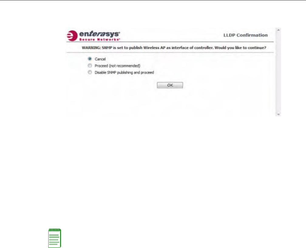
Configuring Wireless AP Settings
3-34 Configuring the Wireless AP
IfSNMPisenabledontheEnterasysWirelessControllerandyouenableLLDP,theLLDP
Confirmationdialogisdisplayed.
–Selectoneofthefollowing:
‐Proceed(notrecommended)—SelectthisoptiontoenableLLDPandkeepSNMP
running,andthenclickOK.
‐DisableSNMPpublishing,andproceed—SelectthisoptiontoenableLLDPand
disableSNMP,andthenclickOK.
FormoreinformationonenablingSNMP,seetheEnterasysWirelessConvergence
SoftwareMaintenanceGuide.
–AnnouncementInterval—IfLLDPisenabled,typehowoftentheWirelessAPadvertises
itsinformationbysendinganewLLDPpacket.Thisvalueismeasuredinseconds.
IftherearenochangestotheWirelessAPconfigurationthatimpacttheLLDP
information,theWirelessAPsendsanewLLDPpacketaccordingtothisschedule.
–AnnouncementDelay—IfLLDPisenabled,typetheannouncementdelay.Thisvalueis
measuredinseconds.IfachangetotheWirelessAPconfigurationoccurswhichimpacts
theLLDPinformation,theWirelessAPsendsanupdatedLLDPpacket.The
announcementdelayisthelengthoftimethatdelaysthenewpacketdelivery.The
announcementdelayhelpsminimizeLLDPpackettraffic.
–RealCapture—ClickStarttostartrealcaptureserverontheAP.Thisfeaturecanbe
enabledforeachAPindividually.Statisticsarecapturedusinganexternalconnectiontoa
WindowsWireSharkclient.InWireshark,byselectingtheremoteAPs’IPaddressand
nullauthentication,thewiredandenabledwirelessinterfacesarelistedasavailablefor
capture.Defaultcaptureservertimeoutissetto300secondsandthemaximum
configurabletimeoutis1hour.CapturestatisticsarefoundontheActiveWirelessAPs
report(seeViewingStatisticsforWirelessAPs).
5. ClickClose.TheAdvanceddialogisclosed.
6. Tosaveyourchanges,clickSave.
To Modify a Wireless AP’s Properties as a Sensor:
1. Fromthetopmenu,clickWirelessAPs.TheWirelessAPscreenisdisplayed.
Note: The Time to Live value cannot be directly edited. The Time to Live value is calculated as
four times the Announcement Interval value.
DRAFT
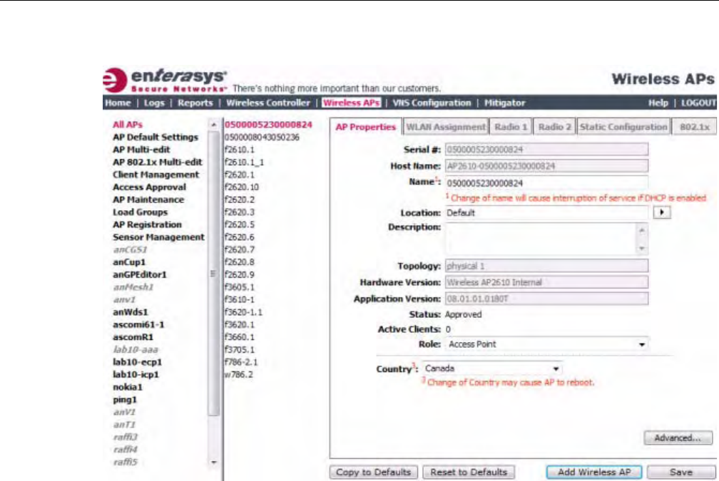
Configuring Wireless AP Settings
User Guide, V8.01 3-35
2. IntheWirelessAPlist,clicktheWirelessAPwhosepropertiesyouwanttomodify.TheAP
PropertiestabdisplaysWirelessAPinformation.
3. ModifytheWirelessAP’sinformation:
–Name—TypeauniquenamefortheWirelessAPthatidentifiestheAP.Thedefaultvalue
istheWirelessAP’sserialnumber.
–HostName—Thisvalue,whichisbebasedonAPName,cannotbedirectlyedited.This
valuedepictstheAPHost‐Namevalue.IftheAPNamevaluedoesbeginwithanumber,
forexamplewhenitistheAPʹsserialnumber,theAPʹsmodelisprependedtothevalue.
ThisvalueisusedfortrackingpurposesontheDHCPserver.
–Location—ThelocationoftheWirelessAP.
–Description—TypecommentsfortheWirelessAP.
–Role—ClicktherolefortheAP,eitherAccessPointorSensor.OncetheAPisconfigured
asaSensor,theAPnolongerperformsRFservicesandisnolongermanagedbythe
EnterasysWirelessController.Formoreinformation,see“ConfiguringanAPasaSensor”
onpage 3‐119.
4. Tosaveyourchanges,clickSave.
Assigning Wireless AP Radios to a VNS
TherearethreemethodsofassigningWirelessAPradiostoaVNS:
•VNSconfiguration—WhenaVNSisconfigured,youcanassignWirelessAPradiostothe
VNSthroughitsassociatedWLANService.Formoreinformation,see“ConfiguringWLAN
Services”onpage 6‐1.
DRAFT
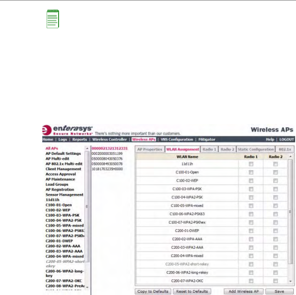
Configuring Wireless AP Settings
3-36 Configuring the Wireless AP
•APMulti‐edit—WhenyouconfiguremultipleWirelessAPssimultaneously,youcanusethe
APMulti‐editfeature.Formoreinformation,see“ConfiguringMultipleWirelessAPs
Simultaneously”onpage 3‐108.
•WirelessAPconfiguration—WhenyouconfigureanindividualWirelessAP,youcanassign
itsradiostoaspecificWLANService.
To Assign Wireless AP Radios When Configuring an Individual Wireless AP:
1. Fromthetopmenu,clickWirelessAPs.TheWirelessAPscreenisdisplayed.
2. ClicktheappropriateWirelessAPinthelist.TheAPPropertiestabisdisplayed.
3. ClicktheWLANAssignmenttab.
4. IntheRadio1andRadio2columns,selecttheWirelessAPradiosthatyouwanttoassignfor
eachWLANService.
5. Tosaveyourchanges,clickSave.
Configuring Wireless AP Radio Properties
ModifyingWirelessAPradiopropertiescanvarysignificantlydependingonthemodelofthe
WirelessAPyourareconfiguring:
•ForspecificinformationonmodifyingaWireless802.11nAP,see“ModifyingWireless
802.11nAP3605/3610/3620/3660/W78xCRadioProperties”onpage 3‐38.
•ForspecificinformationonmodifyingaWirelessAP2610/2620orEnterasysWirelessOutdoor
AP,see“ModifyingWirelessAP2610/2620RadioProperties”onpage 3‐52.
Note: To configure foreign Wireless AP radios to a VNS, use the VNS configuration method.
Foreign Wireless APs are only listed and available for VNS assignment from the WLAN Services
tab. For more information, see Chapter 7, Configuring a VNS.
DRAFT

Configuring Wireless AP Settings
User Guide, V8.01 3-37
Dynamic Radio Management (DRM)
WhenyoumodifyaWirelessAP’sradioproperties,theDynamicRadioManagement(DRM)
functionalityoftheEnterasysWirelessControllercanbeusedtohelpestablishtheoptimumradio
configurationforyourWirelessAPs.DRMisenabledbydefault.TheEnterasysWireless
Controller’sDRM:
•AdjuststransmitpowerlevelstobalancecoveragebetweenWirelessAPsassignedtothesame
RFdomainandoperatingonthesamechannel.
•ScansandcoordinateswithotherWirelessAPstoselectanoptimaloperatingchannel.
TheDRMfeatureconsistsofthreefunctions:
•AutoChannelSelection(ACS)—ACSprovidesaneasywaytooptimizechannel
arrangementbasedonthecurrentsituationinthefield.ACSprovidesanoptimalsolution
onlyifitistriggeredonallWirelessAPsinadeployment.TriggeringACSonasingleWireless
APoronasubsetofWirelessAPsprovidesausefulbutsuboptimalsolution.Also,ACSonly
reliesontheinformationobservedatthetimeitistriggered.OnceaWirelessAPhasselecteda
channel,itwillremainoperatingonthatchanneluntiltheuserchangesthechannelortriggers
ACS.
ACScanbetriggeredbyoneofthefollowingevents:
–AnewWirelessAPregisterswiththeEnterasysWirelessControllerandtheAPDefault
SettingschannelisAuto.
–AuserselectsAutofromtheRequestNewChanneldrop‐downlistontheWirelessAP’s
radioconfigurationtabs.
–AuserselectsAutofromtheChanneldrop‐downlistontheAPMulti‐editscreen.
–IfDynamicChannelSelection(DCS)isenabledinactivemodeandaDCSthresholdis
exceeded.
–AWirelessAPdetectsradaronitscurrentoperatingchannelanditemploysACStoselect
anewchannel.
–ChannelPlan—IfACSisenabled,youcandefineachannelplanfortheWirelessAP.
Definingachannelplanallowsyoutolimitwhichchannelsareavailableforuseduringan
ACSscan.Forexample,youmaywanttoavoidusingspecificchannelsbecauseoflow
power,regulatorydomain,orradarinterference.Selectfromthefollowingoptions:
Dependingontheradioused,whendefiningachannelplanyoucaneithercreateyour
customizedchannelplanbyselectingindividualchannelsoryoucanselectadefault3or4
channelplan.
Youcanusethechannelplantoavoidtransmissionoverlapon40MHzchannelsofthe
Wireless802.11nAPs.ToavoidchanneloverlapbetweenWireless802.11nAPsthat
operateon40MHzchannels,configurethechannelplanforthe5GHzradiobandtouse
everyotherchannelavailable.
Ifusinghalfoftheavailablechannelsisnotanoptionforyourenvironment,donot
configureachannelplan.Instead,allowACStoselectfromallavailablechannels.This
alternatesolutionmaycontributetoincreasedcongestionontheextensionchannels.
Note: ACS in the 2.4GHz radio band with 40MHz channels is not recommended due to severe co-
channel interference.
DRAFT

Configuring Wireless AP Settings
3-38 Configuring the Wireless AP
•DynamicChannelSelection(DCS)—DCSallowsaWirelessAPtomonitortrafficandnoise
levelsonthechannelonwhichtheWirelessAPiscurrentlyoperating.DCScanoperateintwo
modes:
–Monitor—WhenDCSisenabledinmonitormodeandtrafficornoiselevelsexceedthe
configuredDCSthresholds,analarmistriggeredandaninformationlogisgenerated.
TheDCSmonitoralarmisusedforevaluatingtheRFenvironmentofyourdeployed
WirelessAPs.
–Active—WhenDCSisenabledinactivemodeandtrafficornoiselevelsexceedthe
configuredDCSthresholds,analarmistriggeredandaninformationlogisgenerated.In
addition,theWirelessAPwillceaseoperatingonthecurrentchannelandACSwillbe
employedtoselectanalternatechannelfortheWirelessAPtooperateon.DCSwillnot
triggerchannelchangesonneighboringWirelessAPs.
•AutoTxPowerControl(ATPC)—ATPCguaranteesyourLANastableRFenvironmentby
automaticallyadaptingtransmissionpowersignalsaccordingtothecoverageprovidedbythe
WirelessAPs.ATPCcanbeeitherenabledordisabled.
WhenyoudisableATPC,youaregiventheoptionofautomaticallyadjustingtheMaxTx
PowersettingtomatchtheCurrentTxPowerLevel.InthecaseofAPMulti‐edit,ifyoureply
yes,theneachindividualWirelessAPʹsMaxTxPowersettingwillbeadjustedtocorrespond
withitsCurrentTxPowerLevelinthedatabase.
Modifying Wireless 802.11n AP 3605/3610/3620/3660/W78xC Radio Properties
TheWireless802.11nAP3605/3610/3620/3660/W78xCare802.11n‐compliantaccesspoints.The
followingsectiondescribeshowtomodifyaWireless802.11nAP.
ForinformationonhowtomodifyaWirelessAP2610/2620ortheEnterasysWirelessOutdoorAP,
see“ModifyingWirelessAP2610/2620RadioProperties”onpage 3‐52.
Channel Bonding
ChannelbondingimprovestheeffectivethroughputofthewirelessLAN.Incontrasttothe
WirelessAP26xxwhichusesradiochannelspacingsthatareonly20MHzwide,theWireless
802.11nAPcanusetwochannelsatthesametimetocreatea40MHzwidechannel.Toachievea
40MHzchannelwidth,theWireless802.11nAPemployschannelbonding—two20MHz
channelsatthesametime.
The40MHzchannelwidthisachievedbybondingtheprimarychannel(20MHz)withan
extensionchannelthatiseither20MHzabove(bondingup)or20MHzbelow(bondingdown)of
theprimarychannel.
DependingontheRadio,channelbondingcanbepredefined:
•Radio1—Bondingpairsarepredefined.
•Radio2—Channelscanbondupordownaslongasthebandedgeisnotexceeded,butsome
channelshavepredefinedbondingdirections.
ChannelbondingisenabledbyselectingtheChannelWidthontheRadiotabs.Whenselecting
ChannelWidth,thefollowingoptionsareavailable:
•20MHz—Channelbondingisnotenabled:
– 802.11nclientsusetheprimarychannel(20MHz)
Note: If DCS is enabled, DCS statistics can be viewed in the Wireless Statistics by Wireless APs
display. For more information, see Chapter 15, Working with Reports and Displays.
DRAFT

Configuring Wireless AP Settings
User Guide, V8.01 3-39
–Non‐802.11nclients,aswellasbeaconsandmulticasts,usethe802.11a/b/gradio
protocols.
•40MHz—Channelbondingisenabled:
– 802.11nclientsthatsupportthe40MHzfrequencycanuse40MHz,20MHz,orthe802.11a/
b/gradioprotocols.
– 802.11nclientsthatdonotsupportthe40MHzfrequencycanuse20MHzorthe802.11a/b/
gradioprotocols.
–Non‐802.11nclients,beacons,andmulticastsusethe802.11a/b/gradioprotocols.
–Iftheprimarychannelallowsforbothbondingtypes(upanddown),youcanselectthe
channelbondingtypefromtheChannelBondingdrop‐downlist.
–Iftheprimarychannelallowsforonlyoneofthebondingtypes(upordown),that
channelbondtypeisdisplayedintheChannelBondingdrop‐downlist.
•Auto—Channelbondingisautomaticallyenabledordisabled,switchingbetween20MHz
and40MHz,dependingonhowbusytheextensionchannelis.Iftheextensionchannelisbusy
aboveaprescribedthresholdpercentage,whichisdefinedinthe40MHzChannelBusy
Thresholdbox,channelbondingisdisabled.
Channel Selection — Primary and Extension
TheprimarychanneloftheWireless802.11nAPisselectedfromtheRequestNewChanneldrop‐
downlist.Ifautoisselected,theACSfeatureselectstheprimarychannel.Dependingonthe
primarychannelthatisselected,channelbondingmaybeallowed:upordown.
Guard Interval
Theguardintervalsensurethatindividualtransmissionsdonotinterferewithoneanother.The
Wireless802.11nAPprovidesashorterguardintervalthatincreasesthechannelthroughput.
Whena40MHzchannelisused,youcanselecttheguardintervaltoimprovethechannel
efficiency.TheguardintervalisselectedfromtheGuardIntervaldrop‐downlist.Longerguard
periodsreducethechannelefficiency.
Aggregate MSDU and MPDU
TheWireless802.11nAPprovidesaggregateMacServiceDataUnit(MSDU)andaggregateMac
ProtocolDataUnit(MPDU)functionality,whichcombinesmultipleframestogetherintoone
largerframeforasingledelivery.Thisaggregationreducestheoverheadofthetransmissionand
resultsinincreasedthroughput.Theaggregatemethodsareenabledanddefinedselectedfromthe
AggregateMSDUsandAggregateMPDUsdrop‐downlists.
DRAFT
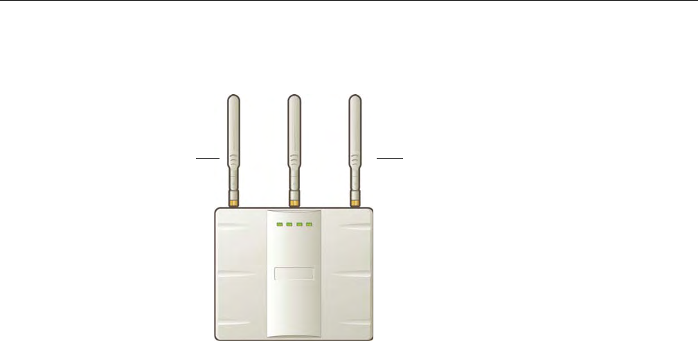
Configuring Wireless AP Settings
3-40 Configuring the Wireless AP
Antenna Selection
TheWireless802.11nAPhasthreeantennas:left,middle,andright.Theillustrationbelow
identifiestheleftandrightantennasfortheAP3620.
TheWireless802.11nAPisconfigured,bydefault,totransmitonallthreeantennas.Dependingon
yourdeploymentrequirements,youcanconfiguretheWireless802.11nAPtotransmitonspecific
antennas.YoucanconfiguretheWireless802.11nAPtotransmitonspecificantennasforboth
radios,includingalltheavailablemodes:
•Radio1—a,a/nmodes
•Radio2—b,b/g,b/g/nmodes
WhenyouconfiguretheWireless802.11nAPtousespecificantennas,thefollowingoccurs:
• Transmissionpowerisrecalculated—TheCurrentTxPowerLevelvaluefortheradiois
automaticallyadjustedtoreflecttherecentantennaconfiguration.Ittakesapproximately30
secondsforthechangetotheCurrentTxPowerLevelvaluetobereflectedintheEnterasys
WirelessAssistant.
•Radioisreset—Theradioisresetcausingclientconnectionsonthisradiotobelost.
To Modify Wireless 802.11n AP Radio Properties:
1. Fromthetopmenu,clickWirelessAPs.TheEnterasysWirelessAPscreenisdisplayed.
2. ClicktheappropriateWireless802.11nAPinthelist.TheAPPropertiestabisdisplayed.
3. ClicktheRadiotabyouwanttomodify.
EachRadiotabdisplaystheradiosettingsforeachradioontheWirelessAP.IftheRadiohas
beenassignedtoaWLANService,theWLANServicenamesandMACaddressesare
displayedintheBaseSettingssection.TheWirelessAPradioscanbeassignedtoeachofthe
configuredWLANServicesinasystem.EachradiocansupporteightWLANassignments,
correspondingtothenumberofSSIDsitcansupport.Oncearadiohasall8slotsassigned,itis
nolongereligibleforfurtherassignment.
TheBSSInfosectionisview‐only.AfterWLANServiceconfiguration,theBasicServiceSet
(BSS)sectiondisplaystheMACaddressontheWirelessAPforeachWLANServiceaswellas
theSSIDsoftheWLANServicestowhichthisradiohasbeenassigned.
Left antenna Right antenna
DRAFT
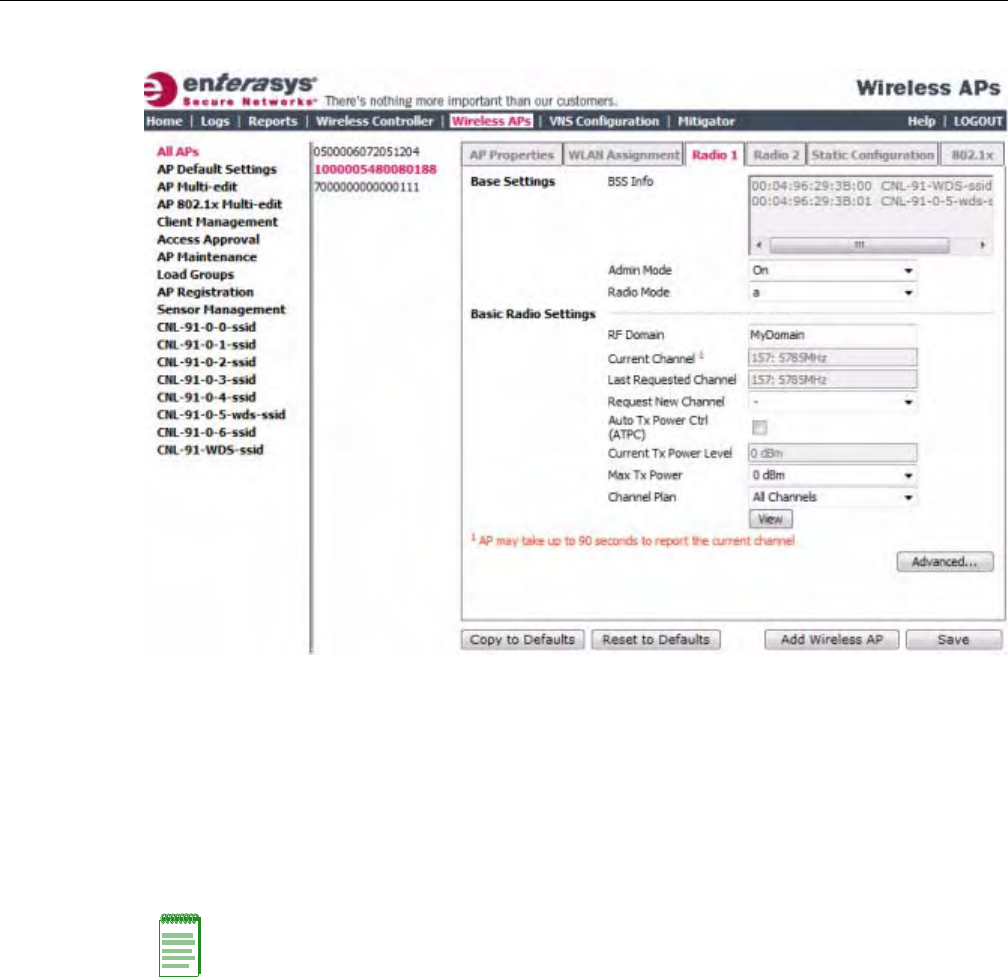
Configuring Wireless AP Settings
User Guide, V8.01 3-41
4. Ifapplicable,clicktheRadio1tab.
5. IntheBaseSettingssection,dothefollowing:
–AdminMode—SelectOntoenabletheradio;selectOfftodisabletheradio.
–RadioMode—Clickoneofthefollowingradiooptions:
‐a—Clicktoenablethe802.11amodeofRadio1without802.11ncapability.
‐a/n—Clicktoenablethe802.11amodeofRadio1with802.11ncapability.
‐n‐strict—Clicktoenablethe802.11amodeofRadio1with802.11nstrictcapability
–ChannelWidth—Clickthechannelwidthfortheradio:
‐20MHz—Clicktoallow802.11nclientstousetheprimarychannel(20MHz)andnon‐
802.11nclients,aswellasbeaconsandmulticasts,tousethe802.11b/gradioprotocols.
‐40MHz—Clicktoallow802.11nclientsthatsupportthe40MHzfrequencytouse
40MHz,20MHz,orthe802.11b/gradioprotocols.802.11nclientsthatdonotsupport
the40MHzfrequencycanuse20MHzorthe802.11b/gradioprotocolsandnon‐
802.11nclients,beacons,andmulticastsusethe802.11b/gradioprotocols.
‐Auto—Clicktoautomaticallyswitchbetween20MHzand40MHzchannelwidths,
dependingonhowbusytheextensionchannelis.
Note: Depending on the radio modes you select, some of the radio settings may not be available for
configuration. The Wireless AP hardware version dictates the available radio modes.
DRAFT

Configuring Wireless AP Settings
3-42 Configuring the Wireless AP
6. IntheBasicRadioSettingssection,dothefollowing:
–RFDomain—TypeastringthatuniquelyidentifiesagroupofAPsthatcooperatein
managingRFchannelsandtransmissionpowerlevels.Themaximumlengthofthestring
is16characters.TheRFDomainisusedtoidentifyagroupofWirelessAPs.
–RequestNewChannel—ClickthewirelesschannelyouwanttheWireless802.11nAPto
usetocommunicatewithwirelessdevices.
ClickAutotorequesttheACStosearchforanewchannelfortheWirelessAP,usinga
channelselectionalgorithm.ThisforcestheWirelessAPtogothroughtheauto‐channel
selectionprocessagain.
Dependingontheregulatorydomain(basedoncountry),somechannelsmaybe
restricted.ThedefaultvalueisbasedonNorthAmerica.Formoreinformation,see
Appendix B.
–AutoTxPowerCtrl(ATPC)—SelecttoenableATPC.ATPCautomaticallyadapts
transmissionpowersignalsaccordingtothecoverageprovidedbytheWirelessAPs.After
aperiodoftime,thesystemwillstabilizeitselfbasedontheRFcoverageofyourWireless
APs.
–ChannelBonding—Clickthebondingmethod,UporDown.Theprimarychannel
(20MHz)isbondedwithanextensionchannelthatiseither20MHzabove(bondingup)or
20MHzbelow(bondingdown)oftheprimarychannel.Notethattheavailablechoicesfor
ChannelBondinginthedrop‐downlistmaydependonthechannelfirstselectedin
RequestNewChannel.
–GuardInterval—Clickaguardinterval,LongorShort,whena40MHzchannelisused.
Enterasysrecommendsthatyouuseashortguardintervalinsmallrooms(forexample,a
smallofficespace)andalongguardintervalinlargerooms(forexample,aconference
hall).
–MaxTxPower—ClickthemaximumTxpowerleveltowhichtherangeoftransmit
powercanbeadjusted:0to24dBm.Enterasysrecommendsthatyouselect24dBmtouse
theentirerangeofpotentialTxpower.
–MinTxPower—IfATPCisenabled,clicktheminimumTxpowerleveltowhichthe
rangeoftransmitpowercanbeadjusted.Enterasysrecommendsthatyouselectthe
lowestvalueavailabletousetheentirerangeofpotentialTxpower.
–AutoTxPowerCtrlAdjust—IfATPCisenabled,clicktheTxpowerlevelthatcanbe
usedtoadjusttheATPCpowerlevelsthatthesystemhasassigned.Enterasys
recommendsthatyoutouse0dBduringyourinitialconfiguration.IfyouhaveanRFplan
Note: ACS in the 2.4GHz radio band with 40MHz channels is not recommended due to severe co-
channel interference.
Note: If you disable ATPC, you can still choose to maintain using the current Tx power setting
ATPC had established. If you elect to maintain using the ATPC power setting, the displayed Current
Tx Power Level value becomes the new Max Tx Power value for the Wireless AP.
Note: In reality, the lowest achievable power level is 5 dBm for the Wireless 802.11n AP 3610 and 2
dBm for the Wireless 802.11n AP 3620. If you assign a lower value, it will automatically default to
the lowest achievable level.
Note: The Minimum Tx Power level is subject to the regulatory compliance requirement for the
selected country.
DRAFT
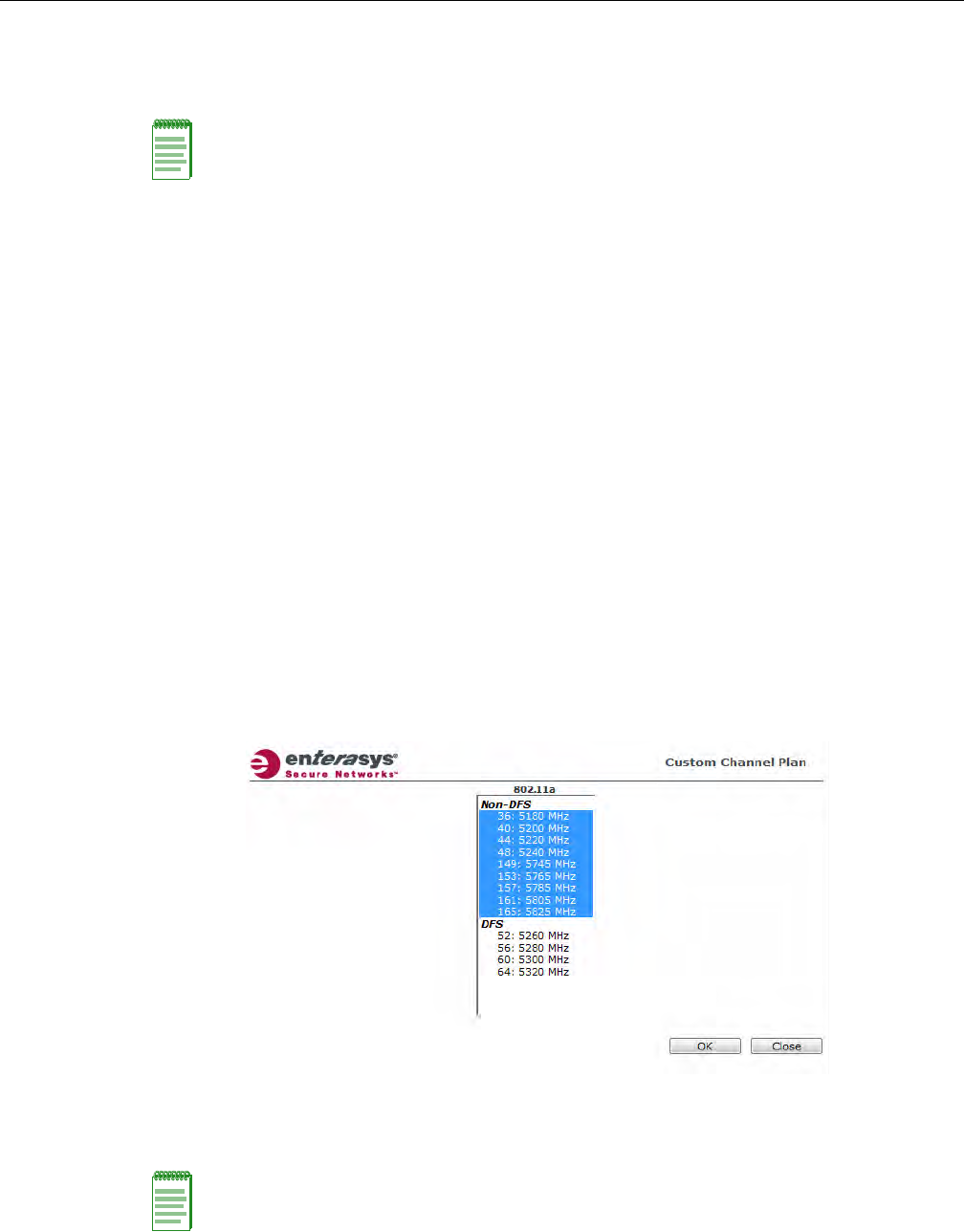
Configuring Wireless AP Settings
User Guide, V8.01 3-43
thatrecommendedTxpowerlevelsforeachWirelessAP,comparetheactualTxpower
levelsyoursystemhasassignedagainsttherecommendedvaluesyourRFplanhas
provided.UsetheAutoTxPowerCtrlAdjustvaluetoachievetherecommendedvalues.
–ChannelPlan—IfACSisenabled,youcandefineachannelplanfortheWirelessAP.
Definingachannelplanallowsyoutolimitwhichchannelsareavailableforuseduringan
ACSscan.Forexample,youmaywanttoavoidusingspecificchannelsbecauseoflow
power,regulatorydomain,orradarinterference.Clickoneofthefollowing:
‐Allchannels—ACSscansallchannelsforanoperatingchannelandreturnsboth
DFSandnon‐DFSchannels,ifavailable.
‐AllNon‐DFSChannels—ACSscansallnon‐DFSchannelsforanoperatingchannel.
Thisselectionisalwaysavailable,butiftherearenoDFSChannelsavailable,thelistis
thesameastheAllChannelslist.
‐Custom—ToconfigureindividualchannelsfromwhichtheACSwillselectan
operatingchannel,clickConfigure.TheCustomChannelPlandialogdisplays.By
default,allchannelsparticipateinthechannelplan.Clicktheindividualchannelsyou
wanttoincludeinthechannelplan.Toselectcontiguouschannels,usetheShiftkey.
Toselectmultiple,non‐contiguouschannelsinthelist,usetheCTRLkey.ClickOKto
savetheconfiguration.
–AntennaSelection—Clicktheantenna,orantennacombination,youwanttoconfigure
onthisradio.
Note: The following fields are view only.
• Current Channel — The actual channel the ACS has assigned to the Wireless AP radio. The
Current Channel value and the Last Requested Channel value may be different because the
ACS automatically assigns the best available channel to the Wireless AP, ensuring that a Wireless
AP’s radio is always operating on the best available channel.
• Last Requested Channel — The last wireless channel that you had selected to communicate
with the wireless devices.
• Current Tx Power Level — The actual Tx power level used by the Wireless AP radio.
Note: When you configure the Wireless 802.11n AP to use specific antennas, the transmission
power is recalculated; the Current Tx Power Level value for the radio is automatically adjusted to
reflect the recent antenna configuration. It takes approximately 30 seconds for the change to the
Current Tx Power Level value to be reflected in the Enterasys Wireless Assistant. Also, the radio
is reset which may cause client connections on this radio to be lost.
DRAFT

Configuring Wireless AP Settings
3-44 Configuring the Wireless AP
7. TomodifyRadio1advancedsettings,clickAdvanced.TheAdvanceddialogisdisplayed.
8. IntheAdvanceddialogRadioSettingssection,dothefollowing:
–DTIMPeriod—TypethedesiredDTIM(DeliveryTrafficIndicationMessage)period—
thenumberofbeaconintervalsbetweentwoDTIMbeacons.Toensurethebestclient
powersavings,usealargenumber.Useasmallnumbertominimizebroadcastand
multicastdelay.Thedefaultvalueis5.
–BeaconPeriod—Typethedesiredtime,inmilliseconds,betweenbeacontransmissions.
Thedefaultvalueis100milliseconds.
–RTS/CTSThreshold—Typethepacketsizethreshold,inbytes,abovewhichthepacket
willbeprecededbyanRTS/CTS(RequesttoSend/CleartoSend)handshake.Thedefault
valueis2346,whichmeansallpacketsaresentwithoutRTS/CTS.Reducethisvalueonlyif
necessary.
–Frag.Threshold—Typethefragmentsizethreshold,inbytes,abovewhichthepackets
willbefragmentedbytheWirelessAPpriortotransmission.Thedefaultvalueis2346,
whichmeansallpacketsaresentunfragmented.Reducethisvalueonlyifnecessary.
–Max%ofnon‐unicasttrafficperBeaconperiod—Enterthemaximumpercentageof
timethattheAPwilltransmitnon‐unicastpackets(broadcastandmulticasttraffic)for
eachconfiguredBeaconPeriod.Foreachnon‐unicastpackettransmitted,thesystem
calculatestheairtimeusedbyeachpacketanddropsallpacketsthatexceedthe
configuredmaximumpercentage.Byrestrictingnon‐unicasttraffic,youlimittheimpact
ofbroadcastsandmulticastsonoverallsystemperformance.
–MaximumDistance—Enteravaluefrom100to15,000metersthatidentifiesthe
maximumlinkdistancebetweenAPsthatparticipateinaWDS.Thisvalueensuresthat
theacknowledgementofcommunicationbetweenAPsdoesnotexceedthetimeoutvalue
predefinedbythe802.11standard.Thedefaultvalueis100meters.Ifthelinkdistance
betweenAPsisgreaterthan100meters,configurethemaximumdistanceupto15,000
meterssothatthesoftwareincreasesthetimeoutvalueproportionallywiththedistance
betweenAPs.
Donotchangethedefaultsettingfortheradiothatprovidesserviceto802.11clientsonly.
–DynamicChannelSelection—ToenableDynamicChannelSelection,clickoneofthe
following:
‐MonitorMode—IftrafficornoiselevelsexceedtheconfiguredDCSthresholds,an
alarmistriggeredandaninformationlogisgenerated.
‐ActiveMode—IftrafficornoiselevelsexceedtheconfiguredDCSthresholds,an
alarmistriggeredandaninformationlogisgenerated.Inaddition,theWirelessAP
willceaseoperatingonthecurrentchannelandACSisemployedtoautomatically
selectanalternatechannelfortheWirelessAPtooperateon.
–DCSNoiseThreshold—Typethenoiseinterferencelevel,measuredindBm,afterwhich
ACSwillscanforanewoperatingchannelfortheWirelessAPifthethresholdis
exceeded.
–DCSChannelOccupancyThreshold—Typethechannelutilizationlevel,measuredasa
percentage,afterwhichACSwillscanforanewoperatingchannelfortheWirelessAPif
thethresholdisexceeded.
–DCSUpdatePeriod—Typethetime,measuredinminutesthatdeterminestheperiod
duringwhichtheWirelessAPaveragestheDCSNoiseThresholdandDCSChannel
OccupancyThresholdmeasurements.Ifeitheroneofthesethresholdsisexceeded,then
theWirelessAPwilltriggerACS.
DRAFT

Configuring Wireless AP Settings
User Guide, V8.01 3-45
–ProtectionMode—Clickaprotectionmode:None,Auto,orAlways.Thedefaultand
recommendedsettingisAuto.ClickNoneif11bAPsandclientsarenotexpected.Click
Alwaysifyouexpectmany11b‐onlyclients.
–ProtectionType—Clickaprotectiontype,CTSOnlyorRTS‐CTS,whena40MHz
channelisused.Thisprotectshighthroughputtransmissionsonextensionchannelsfrom
interferencefromnon‐11nAPsandclients.
–Min.BasicRate—Clickaminimumbasicrate,6Mbps,12Mbps,or24Mbps.
9. IntheAdvanceddialog11nSettingssection,dothefollowing:
–ProtectionMode—Clickaprotectionmode:None,Auto,orAlways.Thedefaultand
recommendedsettingisAuto.ClickNoneif11bAPsandclientsarenotexpected.Click
Alwaysifyouexpectmany11b‐onlyclients.
–ProtectionType—Clickaprotectiontype,CTSOnlyorRTS‐CTS,whena40MHz
channelisused.Thisprotectshighthroughputtransmissionsonextensionchannelsfrom
interferencefromnon‐11nAPsandclients.
–40MHzChannelBusyThreshold—Typetheextensionchannelthresholdpercentage,
whichifexceeded,willdisabletransmissionsontheextensionchannel(40MHz).
–AggregateMSDUs—ClickanaggregateMSDUmode:EnabledorDisabled.Aggregate
MSDUincreasesthemaximumframetransmissionsize.
–AggregateMPDUs—ClickanaggregateMPDUmode:EnabledorDisabled.Aggregate
MPDUprovidesasignificantimprovementinthroughput.
–AggregateMPDUMaxLength—TypethemaximumlengthoftheaggregateMPDU.The
valuerangeis1024‐65535bytes.
–Agg.MPDUMax#ofSub‐frames—Typethemaximumnumberofsub‐framesofthe
aggregateMPDU.Thevaluerangeis2‐64.
–ADDBASupport—ClickanADDBAsupportmode:EnabledorDisabled.ADDBA,or
blockacknowledgement,providesacknowledgementofagroupofframesinsteadofa
singleframe.ADDBASupportmustbeenabledifAggregateAPDUisenable.
–LDPC—ClickanLDPCmode:EnabledorDisabled.LDPCincreasesthereliabilityofthe
transmissionresultingina2dBincreasedperformancecomparedtotraditional11n
coding.
–STBC—ClickanSTBCmode:EnabledorDisabled.STBCisasimpleopenlooptransmit
diversityscheme.Whenenabled,STBCconfigurationis2x1(onespatialstreamsplitinto
twospace‐timestreams).TXBFwilloverrideSTBCifbothareenabledforsinglestream
rates.
–TXBF—ClickanTXBFmode:EnabledorDisabled.TxBeamFormingfocuses
transmissionbeamsdirectlyattheintendedreceiverwhilereducingtheoverall
interferencegeneratedbythetransmitter.
10. ClickClose.TheAdvanceddialogisclosed.
11. ClickSavetosaveyourchanges.
12. Ifapplicable,clicktheRadio2tab.
13. IntheBaseSettingssection,dothefollowing:
–AdminMode—SelectOntoenabletheradio;selectOfftodisabletheradio.
–RadioMode—Clickoneofthefollowingradiooptions:
‐b—Clicktoenablethe802.11b‐onlymodeofRadio2.Ifselected,theAPwilluseonly
11b(CCK)rateswithallassociatedclients.
DRAFT

Configuring Wireless AP Settings
3-46 Configuring the Wireless AP
‐g—Clicktoenablethe802.11g‐onlymodeofRadio2.
‐b/g—Clicktoenableboththe802.11gmodeandthe802.11bmodeofRadio2.If
selected,theAPwilluse11b(CCK)and11g‐specific(OFDM)rateswithallofthe
associatedclients.TheAPwillnottransmitorreceive11nrates.
‐g/n—Clicktoenableboththe802.11gmodeandthe802.11nbmodeofRadio2.If
selected,theAPwilluse11nand11g‐specific(OFDM)rateswithalloftheassociated
clients.TheAPwillnottransmitorreceive11brates.
‐b/g/n—Clicktoenableb/g/nmodesofRadio2.Ifselected,theAPwilluseall
available11b,11g,and11nrates.
‐n‐strict—Clicktoenablethe802.11n‐strictmodeofRadio2.Ifselected,theAPcanbe
configuredtouse11n‐strictrateswithalloftheassociatedclients.TheAPwillnot
transmitorreceive11bor11grates.
–ChannelWidth—Clickthechannelwidthfortheradio:
‐20MHz—Clicktoallow802.11nclientstousetheprimarychannel(20MHz)andnon‐
802.11nclients,beacons,andmulticaststousethe802.11b/gradioprotocols.
‐40MHz—Clicktoallow802.11nclientsthatsupportthe40MHzfrequencytouse
40MHz,20MHz,orthe802.11b/gradioprotocols.802.11nclientsthatdonotsupport
the40MHzfrequencycanuse20MHzorthe802.11b/gradioprotocolsandnon‐
802.11nclients,beacons,andmulticastsusethe802.11b/gradioprotocols.
‐Auto—Clicktoautomaticallyswitchbetween20MHzand40MHzchannelwidths,
dependingonhowbusytheextensionchannelis.
14. IntheBasicRadioSettingssection,dothefollowing:
–RFDomain—TypeastringthatuniquelyidentifiesagroupofAPsthatcooperatein
managingRFchannelsandtransmissionpowerlevels.Themaximumlengthofthestring
is16characters.TheRFDomainisusedtoidentifyagroupofWirelessAPs.
–RequestNewChannel—ClickthewirelesschannelyouwanttheWireless802.11nAPto
usetocommunicatewithwirelessdevices.
ClickAutotorequesttheACStosearchforanewchannelfortheWireless802.11nAP,
usingachannelselectionalgorithm.ThisforcestheWireless802.11nAPtogothroughthe
auto‐channelselectionprocessagain.
Dependingontheregulatorydomain(basedoncountry),somechannelsmaybe
restricted.Formoreinformation,seeAppendix B.
–AutoTxPowerCtrl(ATPC)—SelecttoenableATPC.ATPCautomaticallyadapts
transmissionpowersignalsaccordingtothecoverageprovidedbytheWirelessAPs.After
aperiodoftime,thesystemwillstabilizeitselfbasedontheRFcoverageofyourWireless
APs.
Note: Depending on the radio modes you select, some of the radio settings may not be available for
configuration.
Note: ACS in the 2.4GHz radio band with 40MHz channels is not recommended due to severe co-
channel interference.
Note: If you disable ATPC, you can still choose to maintain using the current Tx power setting
ATPC had established. If you elect to maintain using the ATPC power setting, the displayed Current
Tx Power Level value becomes the new Max Tx Power value for the Wireless AP.
DRAFT

Configuring Wireless AP Settings
User Guide, V8.01 3-47
–ChannelBonding—Clickthebondingmethod,UporDown.Theprimarychannel
(20MHz)isbondedwithanextensionchannelthatiseither20MHzabove(bondingup)or
20MHzbelow(bondingdown)oftheprimarychannel.Notethattheavailablechoicesfor
ChannelBondinginthedrop‐downlistmaydependonthechannelfirstselectedin
RequestNewChannel.
–GuardInterval—Clickaguardinterval,LongorShort,whena40MHzchannelisused.
Enterasysrecommendsthatyouuseashortguardintervalinsmallrooms(forexample,a
smallofficespace)andalongguardintervalinlargerooms(forexample,aconference
hall).
–MaxTxPower—ClickthemaximumTxpowerleveltowhichtherangeoftransmit
powercanbeadjusted:0to23dBm.Enterasysrecommendsthatyouselect23dBmtouse
theentirerangeofpotentialTxpower.
–MinTxPower—IfATPCisenabled,clicktheminimumTxpowerleveltowhichthe
rangeoftransmitpowercanbeadjusted.Enterasysrecommendsthatyouselectthe
lowestvalueavailabletousetheentirerangeofpotentialTxpower.
–AutoTxPowerCtrlAdjust—IfATPCisenabled,clicktheTxpowerlevelthatcanbe
usedtoadjusttheATPCpowerlevelsthatthesystemhasassigned.Enterasys
recommendsthatyouuse0dBduringyourinitialconfiguration.IfyouhaveanRFplan
thatrecommendsTxpowerlevelsforeachWirelessAP,comparetheactualTxpower
levelsyoursystemhasassignedagainsttherecommendedvaluesyourRFplanhas
provided.UsetheAutoTxPowerCtrlAdjustvaluetoachievetherecommendedvalues.
–ChannelPlan—IfACSisenabled,youcandefineachannelplanfortheWirelessAP.
Definingachannelplanallowsyoutolimitwhichchannelsareavailableforuseduringan
ACSscan.Forexample,youmaywanttoavoidusingspecificchannelsbecauseoflow
power,regulatorydomain,orradarinterference.Clickoneofthefollowing:
‐3ChannelPlan—ACSwillscanthefollowingchannels:1,6,and11inNorth
America,and1,7,and13inmostotherpartsoftheworld.
‐4ChannelPlan—ACSwillscanthefollowingchannels:1,4,7,and11inNorth
America,and1,5,9,and13inmostotherpartsoftheworld.
‐Auto—ACSwillscanthedefaultchannelplanchannels:1,6,and11inNorth
America,and1,5,9,and13inmostotherpartsoftheworld.
Note: The lowest Max Tx Power level that can be assigned is 5 dBm for the Wireless 802.11n AP
3610 and 4 dBm for the Wireless 802.11n AP 3620; a lower Max Tx Power level assignment will
automatically default to the lowest allowed levels.
Note: The Minimum Tx Power level is subject to the regulatory compliance requirement for the
selected country.
Note: The following fields are view only.
• Current Channel — The actual channel the ACS has assigned to the Wireless AP radio. The
Current Channel value and the Last Requested Channel value may be different because the
ACS automatically assigns the best available channel to the Wireless AP, ensuring that a Wireless
AP’s radio is always operating on the best available channel.
• Last Requested Channel — The last wireless channel that you had selected to communicate
with the wireless devices.
• Current Tx Power Level — The actual Tx power level assigned to the Wireless AP radio.
DRAFT
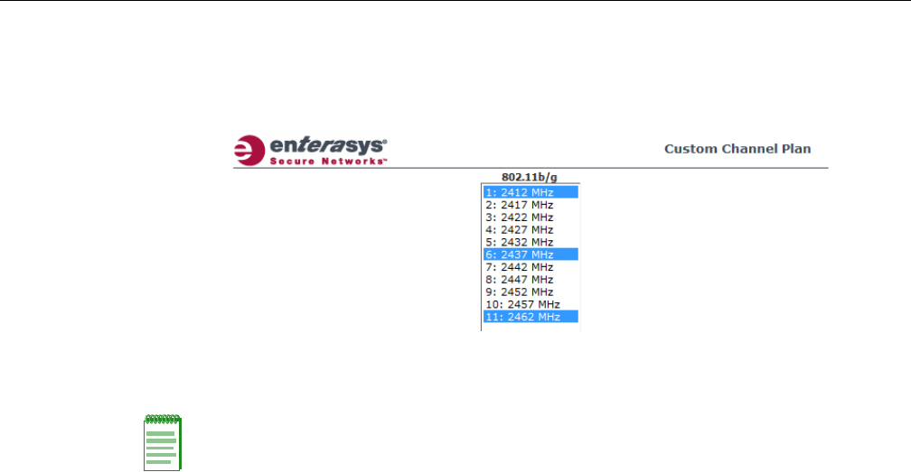
Configuring Wireless AP Settings
3-48 Configuring the Wireless AP
‐Custom—IfyouwanttoconfigureindividualchannelsfromwhichtheACSwill
selectanoperatingchannel,clickConfigure.TheAddChannelsdialogisdisplayed.
Clicktheindividualchannelsyouwanttoaddtothechannelplanwhilepressingthe
CTRLkey,andthenclickOK.
–AntennaSelection—Clicktheantenna,orantennacombination,youwanttoconfigure
onthisradio.
15. TomodifyRadio2advancedsettings,clickAdvanced.TheAdvanceddialogisdisplayed.
16. IntheAdvanceddialogBaseSettingssection,dothefollowing:
–DTIMPeriod—TypethedesiredDTIM(DeliveryTrafficIndicationMessage)period—
thenumberofbeaconintervalsbetweentwoDTIMbeacons.Toensurethebestclient
powersavings,usealargenumber.Useasmallnumbertominimizebroadcastand
multicastdelay.Thedefaultvalueis5.
–BeaconPeriod—Typethedesiredtime,inmilliseconds,betweenbeacontransmissions.
Thedefaultvalueis100milliseconds.
–RTS/CTSThreshold—Typethepacketsizethreshold,inbytes,abovewhichthepacket
willbeprecededbyanRTS/CTS(RequesttoSend/CleartoSend)handshake.Thedefault
valueis2346,whichmeansallpacketsaresentwithoutRTS/CTS.Reducethisvalueonlyif
necessary.
–Frag.Threshold—Typethefragmentsizethreshold,inbytes,abovewhichthepackets
willbefragmentedbytheWirelessAPpriortotransmission.Thedefaultvalueis2346,
whichmeansallpacketsaresentunfragmented.Reducethisvalueonlyifnecessary.
–Max%ofnon‐unicasttrafficperBeaconperiod—Enterthemaximumpercentageof
timethattheAPwilltransmitnon‐unicastpackets(broadcastandmulticasttraffic)for
eachconfiguredBeaconPeriod.Foreachnon‐unicastpackettransmitted,thesystem
calculatestheairtimeusedbyeachpacketanddropsallpacketsthatexceedthe
configuredmaximumpercentage.Byrestrictingnon‐unicasttraffic,youlimittheimpact
ofbroadcastsandmulticastsonoverallsystemperformance.
–MaximumDistance—Enteravaluefrom100to15,000metersthatidentifiesthe
maximumlinkdistancebetweenAPsthatparticipateinaWDS.Thisvalueensuresthat
theacknowledgementofcommunicationbetweenAPsdoesnotexceedthetimeoutvalue
predefinedbythe802.11standard.Thedefaultvalueis100meters.Ifthelinkdistance
betweenAPsisgreaterthan100meters,configurethemaximumdistanceupto15,000
meterssothatthesoftwareincreasesthetimeoutvalueproportionallywiththedistance
betweenAPs.
Note: When you configure the Wireless 802.11n AP to use specific antennas, the transmission
power is recalculated; the Current Tx Power Level value for the radio is automatically adjusted to
reflect the recent antenna configuration. It takes approximately 30 seconds for the change to the
Current Tx Power Level value to be reflected in the Enterasys Wireless Assistant. Also, the radio
is reset which may cause client connections on this radio to be lost.
DRAFT

Configuring Wireless AP Settings
User Guide, V8.01 3-49
–MinBasicRate—Clicktheminimumdataratethatmustbesupportedbyallstationsina
BSS:6,12,or24Mbps.Ifnecessary,theMaxBasicRatechoicesadjustautomaticallytobe
higherorequaltotheMinBasicRate.
Donotchangethedefaultsettingfortheradiothatprovidesserviceto802.11clientsonly.
17. IntheAdvanceddialogBasicRadioSettingssection,dothefollowing:
–DynamicChannelSelection—ToenableDynamicChannelSelection,clickoneofthe
following:
‐MonitorMode—IftrafficornoiselevelsexceedtheconfiguredDCSthresholds,an
alarmistriggeredandaninformationlogisgenerated.
‐ActiveMode—IftrafficornoiselevelsexceedtheconfiguredDCSthresholds,an
alarmistriggeredandaninformationlogisgenerated.Inaddition,theWirelessAP
willceaseoperatingonthecurrentchannelandACSisemployedtoautomatically
selectanalternatechannelfortheWirelessAPtooperateon.
‐DCSNoiseThreshold—Typethenoiseinterferencelevel,measuredindBm,after
whichACSwillscanforanewoperatingchannelfortheWirelessAPifthethreshold
isexceeded.
‐DCSChannelOccupancyThreshold—Typethechannelutilizationlevel,measured
asapercentage,afterwhichACSwillscanforanewoperatingchannelforthe
WirelessAPifthethresholdisexceeded.
‐DCSUpdatePeriod—Typethetime,measuredinminutesthatdeterminesthe
periodduringwhichtheWirelessAPaveragestheDCSNoiseThresholdandDCS
ChannelOccupancyThresholdmeasurements.Ifeitheroneofthesethresholdsis
exceeded,thentheWirelessAPwilltriggerACS.
18. IntheAdvanceddialog11bSettingssection,dothefollowing:
–Preamble—Clickapreambletypefor11b‐specific(CCK)rates:ShortorLong.Click
Shortifyouaresurethatthereisnopre‐11bAPoraclientinthevicinityofthisWireless
802.11nAP.ClickLongifcompatibilitywithpre‐11bclientsisrequired.
19. IntheAdvanceddialog11gSettingssection,dothefollowing:
–ProtectionMode—Clickaprotectionmode:None,Auto,orAlways.Thedefaultand
recommendedsettingisAuto.ClickNoneif11bAPsandclientsarenotexpected.Click
Alwaysifyouexpectmany11b‐onlyclients.
–ProtectionRate—Clickaprotectionrate:1,2,5.5,or11Mbps.Thedefaultand
recommendedsettingis11.Onlyreducetherateiftherearemany11bclientsinthe
environmentorifthedeploymenthasareaswithpoorcoverage.Forexample,rateslower
than11Mbpsarerequiredtoensurecoverage.
–ProtectionType—Clickaprotectiontype:CTSOnlyorRTSCTS.Thedefaultand
recommendedsettingisCTSOnly.ClickRTSCTSonlyifan11bAPthatoperatesonthe
samechannelisdetectedintheneighborhood,oriftherearemany11b‐onlyclientsinthe
environment.
Note: The overall throughput is reduced when Protection Mode is enabled due to the additional
overhead caused by the RTS/CTS. The overhead is minimized by setting Protection Type to CTS
Only and Protection Rate to 11 Mbps. The overhead causes the overall throughput to be
sometimes lower than if just 11b mode is used. If there are many 11b clients, Enterasys
recommends that you disable 11g support (11g clients are backward compatible with 11b APs).
An alternate approach, although potentially a more expensive method, is to dedicate all APs on a
channel for 11b (for example, disable 11g on these APs) and disable 11b on all other APs. The
difficulty with this method is that the number of APs must be increased to ensure coverage
separately for 11b and 11g clients.
DRAFT

Configuring Wireless AP Settings
3-50 Configuring the Wireless AP
20. IntheAdvanceddialog11nSettingssection,dothefollowing:
–ProtectionMode—Clickaprotectionmode:None,Auto,orAlways.Thedefaultand
recommendedsettingisAuto.ClickNoneif11bAPsandclientsarenotexpected.Click
Alwaysifyouexpectmany11b‐onlyclients.
–ProtectionType—Clickaprotectiontype,CTSOnlyorRTS‐CTS,whena40MHz
channelisused.Thisprotectshighthroughputtransmissionsonextensionchannelsfrom
interferencefromnon‐11nAPsandclients.
–40MHzProt.ChannelOffset—Selecta20MHzchanneloffsetifthedeploymentisusing
channelsthatare20MHzapart(forexample,usingchannels1,5,9,and13)ora25MHz
channeloffsetifthedeploymentisusingchannelsthatare25MHzapart(forexample,
usingchannels1,6,and11).
–40MHzChannelBusyThreshold—Typetheextensionchannelthresholdpercentage,
whichifexceeded,willdisabletransmissionsontheextensionchannel(40MHz).
–AggregateMSDUs—ClickanaggregateMSDUmode:EnabledorDisabled.Aggregate
MSDUincreasesthemaximumframetransmissionsize.
–AggregateMPDUs—ClickanaggregateMPDUmode:EnabledorDisabled.Aggregate
MPDUprovidesasignificantimprovementinthroughput.
–AggregateMPDUMaxLength—TypethemaximumlengthoftheaggregateMPDU.The
valuerangeis1024‐65535bytes.
–Agg.MPDUMax#ofSub‐frames—Typethemaximumnumberofsub‐framesofthe
aggregateMPDU.Thevaluerangeis2‐64.
–ADDBASupport—ClickanADDBAsupportmode:EnabledorDisabled.ADDBA,or
blockacknowledgement,providesacknowledgementofagroupofframesinsteadofa
singleframe.ADDBASupportmustbeenabledifAggregateMPDUisenabled.
–LDPC—ClickanLDPCmode:EnabledorDisabled.LDPCincreasesthereliabilityofthe
transmissionresultingina2dBincreasedperformancecomparedtotraditional11n
coding.
–STBC—ClickanSTBCmode:EnabledorDisabled.STBCisasimpleopenlooptransmit
diversityscheme.Whenenabled,STBCconfigurationis2x1(onespatialstreamsplitinto
twospace‐timestreams).TXBFwilloverrideSTBCifbothareenabledforsinglestream
rates.
–TXBF—ClickanTXBFmode:EnabledorDisabled.TxBeamFormingfocuses
transmissionbeamsdirectlyattheintendedreceiverwhilereducingtheoverall
interferencegeneratedbythetransmitter.
21. ClickClose.TheAdvanceddialogisclosed.
22. Tosaveyourchanges,clickSave.
Achieving High Throughput with the Wireless 802.11n AP
Toachievelinkratesofupto300MbpswiththeWireless802.11nAP,configureyoursystemas
describedinthefollowingsection.
Note: Maximum throughput cannot be achieved if both 802.11n and legacy client devices are to be
supported.
Note: Some client devices will choose a 2.4GHz radio even when a 5GHz high-speed radio
network is available; you may need to force those client devices to use only 5GHz if you have
configured high throughput only on the 5GHz radio.
DRAFT

Configuring Wireless AP Settings
User Guide, V8.01 3-51
To Achieve High Throughput with the Wireless 802.11n AP:
1. Fromthetopmenu,clickWirelessAPs.TheWirelessAPscreenisdisplayed.
2. IntheWirelessAPlist,clicktheWireless802.11nAPyouwanttoconfigure.
3. ClicktheRadio2tab,andthendothefollowing:
–IntheRadioModedrop‐downlist,clickb/g/n.
–IntheChannelWidthdrop‐downlist,click40MHz.
–IntheGuardIntervaldrop‐downlist,clickShort.
–Inthe11gSettingssection,clickNoneintheProtectionModedrop‐downlist.
–Ifonly802.11ndevicesarepresent,youmustdisable11nprotectionand40Mzprotection:
‐ProtectionMode—ClickNone.
‐ProtectionType—ClickCTSonlyorRTSCTS.
–AggregateMSDUs—ClickEnabled.
–AggregateMPDU—ClickEnabled.
–AggregateMPDUMaxLength—Click65535
–Agg.MPDUMax#ofSub‐frames—Type64.
–ADDBASupport—ClickEnabled.
4. ClicktheRadio1tab,andthendothefollowing:
–IntheAdminModedrop‐downlist,clicktheOnoption.
–I
ntheRadioModedrop‐downlist,clickthea/noption.
–IntheChannelWidthdrop‐downlist,click40MHz.
–IntheGuardIntervaldrop‐downlist,clickShort.
–Ifonly802.11ndevicesarepresent,youmustdisable11nprotectionand40Mzprotection:
‐ProtectionMode—ClickNone.
‐ProtectionType—ClickCTSonlyorRTSCTS.
–AggregateMSDUs—ClickEnabled.
–AggregateMPDU—ClickEnabled.
–AggregateMPDUMaxLength—ClickEnabled.
–Agg.MPDUMax#ofSub‐frames—Type64.
–ADDBASupport—ClickEnabled.
Note: Some client devices do not support 40MHz in b/g/n mode. To accommodate these clients,
you must enable a/n mode on the Radio 1 tab. Otherwise, the client device will connect at only
130Mbps.
Note: Do not disable 802.11g protection mode if you have 802.11b or 802.11g client devices using
this Wireless AP; instead, configure only Radio 1 for high throughput unless it is acceptable to
achieve less than maximum 802.11n throughput on Radio 2.
Note: Do not disable 802.11n protection mode if you have 802.11b or 802.11g client devices using
this Wireless AP; instead, configure only Radio 1 for high throughput unless it is acceptable to
achieve less than maximum 802.11n throughput on Radio 2.
DRAFT

Configuring Wireless AP Settings
3-52 Configuring the Wireless AP
5. Fromthetopmenu,clickVNSConfiguration.TheVirtualNetworkConfigurationscreenis
displayed.
6. IntheleftpaneVirtualNetworkslist,clicktheVNSyouwanttoconfigure.TheTopologytab
isdisplayed.
7. ClickthePrivacytab.Someclientdeviceswillnotuse802.11nmodeiftheyareusingWEPor
TKIPforsecurity.Therefore,dooneofthefollowing:
–SelectNone.
–SelectWPA‐PSK,andthencleartheWPAv.1 option:
‐SelectWPAv.2.
‐IntheEncryptiondrop‐downlist,clickAESonly.
8. ClicktheQoSPolicytab.
9. IntheWirelessQoSsection,selecttheWMMoption.Some802.11nclientdeviceswillremain
at54MbpsunlessWMMisenabled.
Modifying Wireless AP 2610/2620 Radio Properties
ThefollowingsectiondescribeshowtomodifyaWirelessAP2610/2620andtheEnterasys
WirelessOutdoorAP.ForinformationonhowtomodifyaWireless802.11nAP3605/3610/3620/
3660/W78xC,see“ModifyingWireless802.11nAP3605/3610/3620/3660/W78xCRadioProperties”
onpage 3‐38.
To Modify the Wireless AP’s Radio Properties:
1. Fromthetopmenu,clickWirelessAPs.TheWirelessAPscreenisdisplayed.
2. ClicktheappropriateWirelessAPinthelist.TheAPPropertiestabisdisplayed.
3. ClicktheRadiotabyouwanttomodify.
EachRadiotabdisplaystheradiosettingsforeachradioontheWirelessAP.Iftheradiohas
beenassignedtoaWLANService,theWLANServicenamesandMACaddressesare
displayedintheBaseSettingssection.TheWirelessAPradioscanbeassignedtoeachofthe
configuredWLANServicesinasystem.Eachradiocanbethesubjectof8WLANService
assignments(correspondingtothenumberofSSIDsitcansupport).Oncearadiohasall8
slotsassigned,itisnolongereligibleforfurtherassignment.
TheBSSInfosectionisviewonly.AfterWLANServiceconfiguration,theBasicServiceSet
(BSS)sectiondisplaystheMACaddressontheWirelessAPforeachWLANServiceandthe
SSIDsoftheWLANServicestowhichthisradiohasbeenassigned.
Note: To achieve the strongest encryption protection for your VNS, Enterasys recommends that
you use WPA v.2.
DRAFT
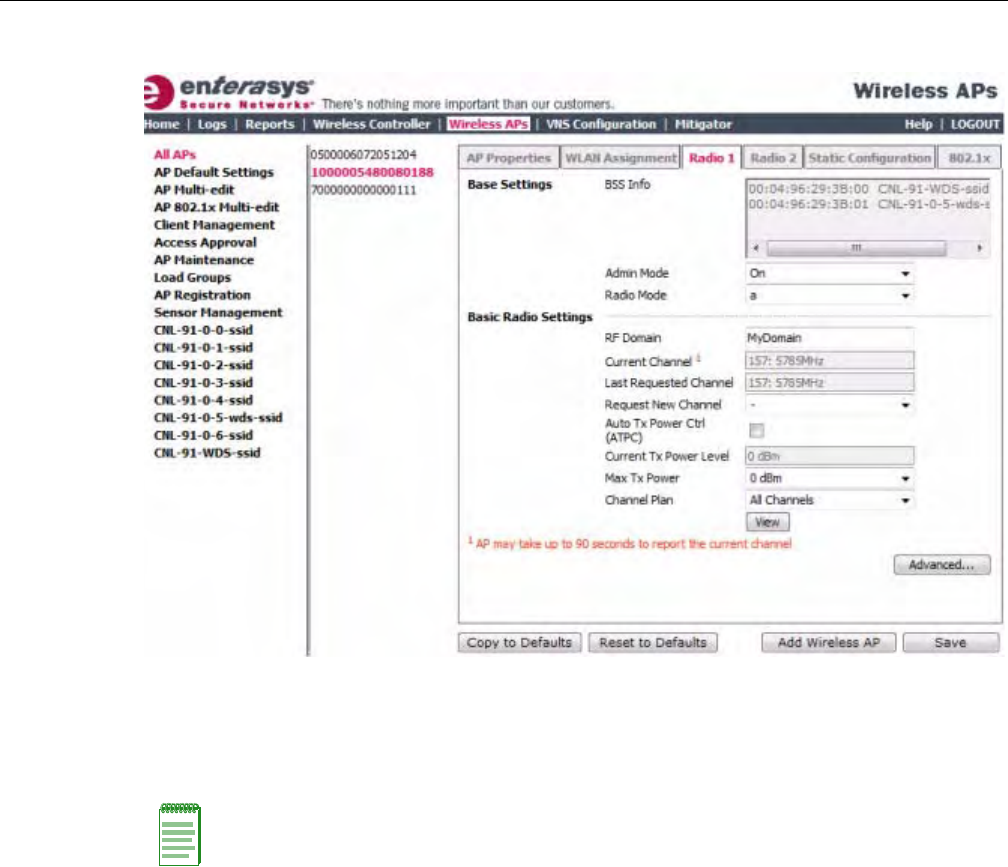
Configuring Wireless AP Settings
User Guide, V8.01 3-53
4. Ifapplicable,clicktheRadio1tab.
5. IntheBaseSettingssection,dothefollowing:
–AdminMode—SelectOntoenabletheradio;selectOfftodisabletheradio.
–RadioMode—Clickatoenable802.11amodeofRadio1.
6. IntheBasicRadioSettingssection,dothefollowing:
–RFDomain—TypeastringthatuniquelyidentifiesagroupofAPsthatcooperatein
managingRFchannelsandtransmissionpowerlevels.Themaximumlengthofthestring
is16characters.TheRFDomainisusedtoidentifyagroupofWirelessAPs.
–RequestNewChannel—ClickthewirelesschannelyouwanttheWirelessAPtouseto
communicatewithwirelessdevices.
ClickAutotorequesttheACStosearchforanewchannelfortheWirelessAP,usinga
channelselectionalgorithm.ThisforcestheWirelessAPtogothroughtheauto‐channel
selectionprocessagain.
Dependingontheregulatorydomain(basedoncountry),somechannelsmaybe
restricted.ThedefaultvalueisbasedonNorthAmerica.Formoreinformation,see
Appendix B.
–AutoTxPowerCtrl(ATPC)—SelecttoenableATPC.ATPCautomaticallyadapts
transmissionpowersignalsaccordingtothecoverageprovidedbytheWirelessAPs.After
aperiodoftime,thesystemwillstabilizeitselfbasedontheRFcoverageofyourWireless
APs.
Note: The Wireless AP hardware version dictates the available radio modes.
DRAFT

Configuring Wireless AP Settings
3-54 Configuring the Wireless AP
–MaxTxPower—ClickthemaximumTxpowerleveltowhichtherangeoftransmit
powercanbeadjusted:0to23dBm.Enterasysrecommendsthatyouselect23dBmtouse
theentirerangeofpotentialTxpower.
–MinTxPower—IfATPCisenabled,clicktheminimumTxpowerleveltowhichthe
rangeoftransmitpowercanbeadjusted.Enterasysrecommendsthatyouselectthe
lowestvalueavailabletousetheentirerangeofpotentialTxpower.
–AutoTxPowerCtrlAdjust—IfATPCisenabled,clicktheTxpowerlevelthatcanbe
usedtoadjusttheATPCpowerlevelsthatthesystemhasassigned.Enterasys
recommendsthatyouuse0dBduringyourinitialconfiguration.IfyouhaveanRFplan
thatrecommendsTxpowerlevelsforeachWirelessAP,comparetheactualTxpower
levelsyoursystemhasassignedagainsttherecommendedvaluesyourRFplanhas
provided.UsetheAutoTxPowerCtrlAdjustvaluetoachievetherecommendedvalues.
–ChannelPlan—IfACSisenabled,youcandefineachannelplanfortheWirelessAP.
Definingachannelplanallowsyoutolimitwhichchannelsareavailableforuseduringan
ACSscan.Forexample,youmaywanttoavoidusingspecificchannelsbecauseoflow
power,regulatorydomain,orradarinterference.Clickoneofthefollowing:
‐Allchannels—ACSscansallchannelsforanoperatingchannelandreturnsboth
DFSandnon‐DFSchannels,ifavailable.
‐AllNon‐DFSChannels—ACSscansallnon‐DFSchannelsforanoperatingchannel.
Thisselectionisalwaysavailable,butiftherearenoDFSChannelsavailable,thelistis
thesameastheAllChannelslist.
‐Custom—ToconfigureindividualchannelsfromwhichtheACSwillselectan
operatingchannel,clickConfigure.TheCustomChannelPlandialogdisplays.By
default,allchannelsparticipateinthechannelplan.Clicktheindividualchannelsyou
wanttoincludeinthechannelplan.Toselectcontiguouschannels,usetheShiftkey.
Note: If you disable ATPC, you can elect to maintain using the current Tx power setting ATPC had
established. If you elect to maintain using the ATPC power setting, the displayed Current Tx Power
Level value becomes the new Max Tx Power value for the Wireless AP.
Note: The Minimum Tx Power level is subject to the regulatory compliance requirement for the
selected country.
Note: The following fields are view only.
• Current Channel — The actual channel the ACS has assigned to the Wireless AP radio. The
Current Channel value and the Last Requested Channel value may be different because the
ACS automatically assigns the best available channel to the Wireless AP, ensuring that a Wireless
AP’s radio is always operating on the best available channel.
• Last Requested Channel — The last wireless channel that you had selected for the Wireless AP
to communicate with the wireless devices.
• Current Tx Power Level — The actual Tx power level assigned to the Wireless AP radio.
DRAFT
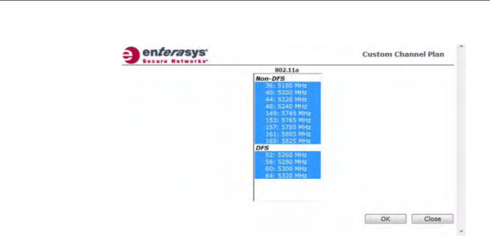
Configuring Wireless AP Settings
User Guide, V8.01 3-55
Toselectmultiple,non‐contiguouschannelsinthelist,usetheCTRLkey.ClickOKto
savetheconfiguration.
7. TomodifyRadio1advancedsettings,clickAdvanced.TheAdvanceddialogisdisplayed.
8. IntheAdvanceddialogBaseSettingssection,dothefollowing:
–DTIMPeriod—TypethedesiredDTIM(DeliveryTrafficIndicationMessage)period—
thenumberofbeaconintervalsbetweentwoDTIMbeacons.Toensurethebestclient
powersavings,usealargenumber.Forexample,5.Useasmallnumbertominimize
broadcastandmulticastdelay.Thedefaultvalueis5.
–BeaconPeriod—Typethedesiredtime,inmilliseconds,betweenbeacontransmissions.
Thedefaultvalueis100milliseconds.
–RTS/CTSThreshold—Typethepacketsizethreshold,inbytes,abovewhichthepacket
willbeprecededbyanRTS/CTS(RequesttoSend/CleartoSend)handshake.Thedefault
valueis2346,whichmeansallpacketsaresentwithoutRTS/CTS.Reducethisvalueonlyif
necessary.
–Frag.Threshold—Typethefragmentsizethreshold,inbytes,abovewhichthepackets
willbefragmentedbytheWirelessAPpriortotransmission.Thedefaultvalueis2346,
whichmeansallpacketsaresentunfragmented.Reducethisvalueonlyifnecessary.
–Max%ofnon‐unicasttrafficperBeaconperiod—Enterthemaximumpercentageof
timethattheAPwilltransmitnon‐unicastpackets(broadcastandmulticasttraffic)for
eachconfiguredBeaconPeriod.Foreachnon‐unicastpackettransmitted,thesystem
calculatestheairtimeusedbyeachpacketanddropsallpacketsthatexceedthe
configuredmaximumpercentage.Byrestrictingnon‐unicasttraffic,youlimittheimpact
ofbroadcastsandmulticastsonoverallsystemperformance.
–MaximumDistance—Enteravaluefrom100to15,000metersthatidentifiesthe
maximumlinkdistancebetweenAPsthatparticipateinaWDS.Thisvalueensuresthat
theacknowledgementofcommunicationbetweenAPsdoesnotexceedthetimeoutvalue
predefinedbythe802.11standard.Thedefaultvalueis100meters.Ifthelinkdistance
betweenAPsisgreaterthan100meters,configurethemaximumdistanceupto15,000
meterssothatthesoftwareincreasesthetimeoutvalueproportionallywiththedistance
betweenAPs.
Donotchangethedefaultsettingfortheradiothatprovidesserviceto802.11clientsonly.
DRAFT

Configuring Wireless AP Settings
3-56 Configuring the Wireless AP
–MinBasicRate—Clicktheminimumdataratethatmustbesupportedbyallstationsina
BSS:6,12,or24Mbps.Ifnecessary,theMaxBasicRatechoicesadjustautomaticallytobe
higherorequaltotheMinBasicRate.
–MaxBasicRate—Clickthemaximumdataratethatmustbesupportedbyallstationsin
aBSS:6,12,or24Mbps.Ifnecessary,theMaxBasicRatechoicesadjustautomaticallyto
behigherorequaltotheMinBasicRate.
–MaxOperationalRate—Clickthemaximumdataratethatclientscanoperateatwhile
associatedwiththeWirelessAP:24,36,48,or54Mbps.Ifnecessary,theMaxOperational
RatechoicesadjustautomaticallytobehigherorequaltotheMaxBasicRate.
9. IntheAdvanceddialogBasicRadioSettingssection,dothefollowing:
–DynamicChannelSelection—ToenableDynamicChannelSelection,clickoneofthe
following:
‐MonitorMode—IftrafficornoiselevelsexceedtheconfiguredDCSthresholds,an
alarmistriggeredandaninformationlogisgenerated.
‐ActiveMode—IftrafficornoiselevelsexceedtheconfiguredDCSthresholds,an
alarmistriggeredandaninformationlogisgenerated.Inaddition,theWirelessAP
willceaseoperatingonthecurrentchannelandACSisemployedtoautomatically
selectanalternatechannelfortheWirelessAPtooperateon.
‐DCSNoiseThreshold—Typethenoiseinterferencelevel,measuredindBm,after
whichACSwillscanforanewoperatingchannelfortheWirelessAPifthethreshold
isexceeded.
‐DCSChannelOccupancyThreshold—Typethechannelutilizationlevel,measured
asapercentage,afterwhichACSwillscanforanewoperatingchannelforthe
WirelessAPifthethresholdisexceeded.
‐DCSUpdatePeriod—Typethetime,measuredinminutesthatdeterminesthe
periodduringwhichtheWirelessAPaveragestheDCSNoiseThresholdandDCS
ChannelOccupancyThresholdmeasurements.Ifeitheroneofthesethresholdsis
exceeded,thentheWirelessAPwilltriggerACS.
–RxDiversity—ClickBestforthebestsignalfrombothantennas,orLeftorRightto
chooseeitherofthetwodiversityantennas.Thedefaultandrecommendedselectionis
Best.Ifonlyoneantennaeisconnected,usethecorrespondingLeftorRightdiversity
setting.DonotuseBestiftwoidenticalantennasarenotused.
–TxDiversity—ClickAlternateforthebestsignalfrombothantennas,orLeftorRightto
chooseeitherofthetwodiversityantennas.ThedefaultselectionisAlternatethat
maximizesperformanceformostclients.However,someclientsmaybehaveoddlywith
TxDiversitysettoAlternate.Underthosecircumstances,Enterasysrecommendsthatyou
useeitherLeftorRightforTxDiversity.Ifonlyoneantennaeisconnected,usethe
correspondingLeftorRightdiversitysetting.DonotuseAlternateiftwoidentical
antennasarenotused.
–Total#ofRetriesforBackgroundBK—ClickthenumberofretriesfortheBackground
transmissionqueue.Thedefaultvalueisadaptive(multi‐rate).Therecommendedsetting
isadaptive(multi‐rate).
–Total#ofRetriesforBestEffortBE—ClickthenumberofretriesfortheBestEffort
transmissionqueue.Thedefaultvalueisadaptive(multi‐rate).Therecommendedsetting
isadaptive(multi‐rate).
–Total#ofRetriesforVideoVI—ClickthenumberofretriesfortheVideotransmission
queue.Thedefaultvalueisadaptive(multi‐rate).Therecommendedsettingisadaptive
(multi‐rate).
DRAFT
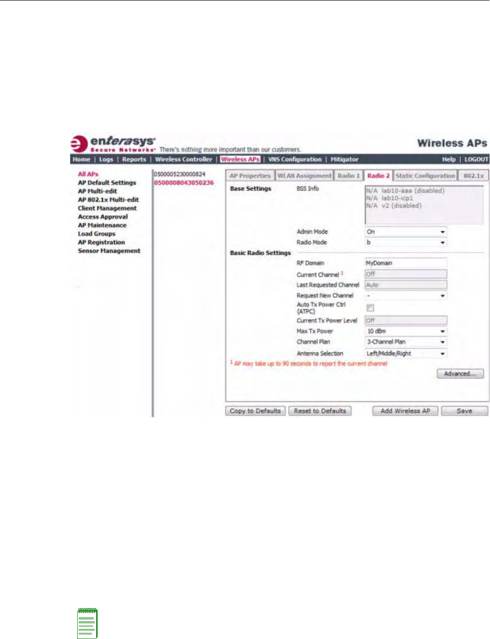
Configuring Wireless AP Settings
User Guide, V8.01 3-57
–Total#ofRetriesforVoic eVO—ClickthenumberofretriesfortheVoicetransmission
queue.Thedefaultvalueisadaptive(multi‐rate).Therecommendedsettingisadaptive
(multi‐rate).
–Total#ofRetriesforTurboVoic eTVO—ClickthenumberofretriesfortheTurboVoice
transmissionqueue.Thedefaultvalueisadaptive(multi‐rate).Therecommendedsetting
isadaptive(multi‐rate).
10. ClickClose.TheAdvanceddialogisclosed.
11. Ifapplicable,clicktheRadio2tab.
12. IntheBaseSettingssection,dothefollowing:
–AdminMode—SelectOntoenabletheradio;selectOfftodisabletheradio.
–RadioMode—Clickoneofthefollowingradiooptions:
‐b—Clicktoenablethe802.11b‐onlymodeofRadio2.Ifselected,theAPwilluseonly
11b(CCK)rateswithallassociatedclients.
‐g—Clicktoselectthe802.11g‐onlymodeofRadio2.Ifselected,theAPwillnot
acceptassociationsfrom11bclients,butitwillstilluseallCCKandOFDM11grates
withitsassociatedclients.TodisableCCKrates,usetheMin/MaxBasicRateand
MaxOperationRatecontrolstoselectOFDM‐onlyrates.
‐b/g—Clicktoenableboththe802.11gmodeandthe802.11bmodeofRadio2.If
selected,theAPwilluse11b(CCK)and11g‐specific(OFDM)rateswithallofthe
associatedclients.TheAPwillnottransmitorreceive11nrates.
Note: Depending on the radio modes you select, some of the radio settings may not be available for
configuration.
DRAFT

Configuring Wireless AP Settings
3-58 Configuring the Wireless AP
13. IntheBasicRadioSettingssection,dothefollowing:
–RFDomain—TypeastringthatuniquelyidentifiesagroupofAPsthatcooperatein
managingRFchannelsandtransmissionpowerlevels.Themaximumlengthofthestring
is16characters.TheRFDomainisusedtoidentifyagroupofWirelessAPs.
–RequestNewChannel—ClickthewirelesschannelyouwanttheWirelessAPtouseto
communicatewithwirelessdevices.
ClickAutotorequesttheACStosearchforanewchannelfortheWirelessAP,usinga
channelselectionalgorithm.ThisforcestheWirelessAPtogothroughtheauto‐channel
selectionprocessagain.
Dependingontheregulatorydomain(basedoncountry),somechannelsmaybe
restricted.ThedefaultvalueisbasedonNorthAmerica.Formoreinformation,see
Appendix B.
–AutoTxPowerCtrl(ATPC)—SelecttoenableATPC.ATPCautomaticallyadapts
transmissionpowersignalsaccordingtothecoverageprovidedbytheWirelessAPs.After
aperiodoftime,thesystemwillstabilizeitselfbasedontheRFcoverageofyourWireless
APs.
–MaxTxPower—ClickthemaximumTxpowerleveltowhichtherangeoftransmit
powercanbeadjusted:8to18dBm.Enterasysrecommendsthatyouselect18dBmtouse
theentirerangeofpotentialTxpower.
–MinTxPower—IfATPCisenabled,clicktheminimumTxpowerleveltowhichthe
rangeoftransmitpowercanbeadjusted.Enterasysrecommendsthatyouselectthe
lowestvalueavailabletousetheentirerangeofpotentialTxpower.
–AutoTxPowerCtrlAdjust—IfATPCisenabled,clicktheTxpowerlevelthatcanbe
usedtoadjusttheATPCpowerlevelsthatthesystemhasassigned.Enterasys
recommendsthatyouuse0dBduringyourinitialconfiguration.IfyouhaveanRFplan
thatrecommendsTxpowerlevelsforeachWirelessAP,comparetheactualTxpower
levelsyoursystemhasassignedagainsttherecommendedvaluesyourRFplanhas
provided.UsetheAutoTxPowerCtrlAdjustvaluetoachievetherecommendedvalues.
–ChannelPlan—IfACSisenabled,youcandefineachannelplanfortheWirelessAP.
Definingachannelplanallowsyoutolimitwhichchannelsareavailableforuseduringan
Note: If you disable ATPC, you can elect to maintain using the current Tx power setting ATPC had
established. If you elect to maintain using the ATPC power setting, the displayed Current Tx Power
Level value becomes the new Max Tx Power value for the Wireless AP.
Note: The Minimum Tx Power level is subject to the regulatory compliance requirement for the
selected country.
Note: The following fields are view only.
• Current Channel — The ACS has assigned to the Wireless AP radio. The Current Channel
value and the Last Requested Channel value may be different because the ACS automatically
assigns the best available channel to the Wireless AP, ensuring that a Wireless AP’s radio is always
operating on the best available channel.
• Last Requested Channel — The last wireless channel that you had selected for the Wireless AP
to communicate with the wireless devices.
• Current Tx Power Level — The actual Tx power level assigned to the Wireless AP radio.
DRAFT
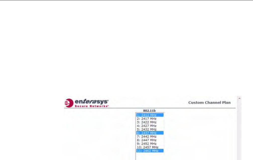
Configuring Wireless AP Settings
User Guide, V8.01 3-59
ACSscan.Forexample,youmaywanttoavoidusingspecificchannelsbecauseoflow
power,regulatorydomain,orradarinterference.Clickoneofthefollowing:
‐3ChannelPlan—ACSwillscanthefollowingchannels:1,6,and11intheUS,and1,
7,and13inEurope.
‐4ChannelPlan—ACSwillscanthefollowingchannels:1,4,7,and11intheUS,and
1,5,9,and13inEurope.
‐Auto—ACSwillscanthedefaultchannelplanchannels:1,6,and11intheUS,and1,
5,9,and13inEurope.
‐Custom—IfyouwanttoconfigureindividualchannelsfromwhichtheACSwill
selectanoperatingchannel,clickConfigure.TheAddChannelsdialogisdisplayed.
Clicktheindividualchannelsyouwanttoaddtothechannelplanwhilepressingthe
CTRLkey,andthenclickOK.
14. TomodifyRadio2advancedsettings,clickAdvanced.TheAdvanceddialogisdisplayed.
15. IntheAdvanceddialogBaseSettingssection,dothefollowing:
–DTIMPeriod—TypethedesiredDTIM(DeliveryTrafficIndicationMessage)period—
thenumberofbeaconintervalsbetweentwoDTIMbeacons.Toensurethebestclient
powersavings,usealargenumber.Forexample,5.Useasmallnumbertominimize
broadcastandmulticastdelay.Thedefaultvalueis5.
–BeaconPeriod—Typethedesiredtime,inmilliseconds,betweenbeacontransmissions.
Thedefaultvalueis100milliseconds.
–RTS/CTSThreshold—Typethepacketsizethreshold,inbytes,abovewhichthepacket
willbeprecededbyanRTS/CTS(RequesttoSend/CleartoSend)handshake.Thedefault
valueis2346,whichmeansallpacketsaresentwithoutRTS/CTS.Reducethisvalueonlyif
necessary.
–Frag.Threshold—Typethefragmentsizethreshold,inbytes,abovewhichthepackets
willbefragmentedbytheWirelessAPpriortotransmission.Thedefaultvalueis2346,
whichmeansallpacketsaresentunfragmented.Reducethisvalueonlyifnecessary.
–Max%ofnon‐unicasttrafficperBeaconperiod—Enterthemaximumpercentageof
timethattheAPwilltransmitnon‐unicastpackets(broadcastandmulticasttraffic)for
eachconfiguredBeaconPeriod.Foreachnon‐unicastpackettransmitted,thesystem
calculatestheairtimeusedbyeachpacketanddropsallpacketsthatexceedthe
configuredmaximumpercentage.Byrestrictingnon‐unicasttraffic,youlimittheimpact
ofbroadcastsandmulticastsonoverallsystemperformance.
–MaximumDistance—Enteravaluefrom100to15,000metersthatidentifiesthe
maximumlinkdistancebetweenAPsthatparticipateinaWDS.Thisvalueensuresthat
theacknowledgementofcommunicationbetweenAPsdoesnotexceedthetimeoutvalue
predefinedbythe802.11standard.Thedefaultvalueis100meters.Ifthelinkdistance
betweenAPsisgreaterthan100meters,configurethemaximumdistanceupto15,000
DRAFT

Configuring Wireless AP Settings
3-60 Configuring the Wireless AP
meterssothatthesoftwareincreasesthetimeoutvalueproportionallywiththedistance
betweenAPs.
–MinBasicRate—Clicktheminimumdataratethatmustbesupportedbyallstationsina
BSS:1,2,5.5,or11Mbps.Ifnecessary,theMaxBasicRatechoicesadjustautomaticallyto
behigherorequaltotheMinBasicRate.
–MaxBasicRate—Clickthemaximumdataratethatmustbesupportedbyallstationsin
aBSS:1,2,5.5,or11Mbps.Ifnecessary,theMaxBasicRatechoicesadjustautomatically
tobehigherorequaltotheMinBasicRate.
–MaxOperationalRate—Clickthemaximumdataratethatclientscanoperateatwhile
associatedwiththeWirelessAP:11,12,18,24,36,48,or54Mbps.Ifnecessary,theMax
OperationalRatechoicesadjustautomaticallytobehigherorequaltotheMaxBasic
Rate.
Donotchangethedefaultsettingfortheradiothatprovidesserviceto802.11clientsonly.
16. IntheAdvanceddialogBasicRadioSettingssection,dothefollowing:
–DynamicChannelSelection—ToenableDynamicChannelSelection,clickoneofthe
following:
‐MonitorMode—IftrafficornoiselevelsexceedtheconfiguredDCSthresholds,an
alarmistriggeredandaninformationlogisgenerated.
‐ActiveMode—IftrafficornoiselevelsexceedtheconfiguredDCSthresholds,an
alarmistriggeredandaninformationlogisgenerated.Inaddition,theWirelessAP
willceaseoperatingonthecurrentchannelandACSisemployedtoautomatically
selectanalternatechannelfortheWirelessAPtooperateon.
‐DCSNoiseThreshold—Typethenoiseinterferencelevel,measuredindBm,after
whichACSwillscanforanewoperatingchannelfortheWirelessAPifthethreshold
isexceeded.
‐DCSChannelOccupancyThreshold—Typethechannelutilizationlevel,measured
asapercentage,afterwhichACSwillscanforanewoperatingchannelforthe
WirelessAPifthethresholdisexceeded.
‐DCSUpdatePeriod—Typethetime,measuredinminutesthatdeterminesthe
periodduringwhichtheWirelessAPaveragestheDCSNoiseThresholdandDCS
ChannelOccupancyThresholdmeasurements.Ifeitheroneofthesethresholdsis
exceeded,thentheWirelessAPwilltriggerACS.
–RxDiversity—ClickBestforthebestsignalfrombothantennas,orLeftorRightto
chooseeitherofthetwodiversityantennas.Thedefaultandrecommendedselectionis
Best.Ifonlyoneantennaeisconnected,usethecorrespondingLeftorRightdiversity
setting.DonotuseBestiftwoidenticalantennasarenotused.
–TxDiversity—ClickAlternateforthebestsignalfrombothantennas,orLeftorRightto
chooseeitherofthetwodiversityantennas.ThedefaultselectionisAlternatethat
maximizesperformanceformostclients.However,someclientsmaybehaveoddlywith
TxDiversitysettoAlternate.Underthosecircumstances,Enterasysrecommendsthatyou
useeitherLeftorRightforTxDiversity.Ifonlyoneantennaeisconnected,usethe
correspondingLeftorRightdiversitysetting.DonotuseAlternateiftwoidentical
antennasarenotused.
–Total#ofRetriesforBackgroundBK—ClickthenumberofretriesfortheBackground
transmissionqueue.Thedefaultvalueisadaptive(multi‐rate).Therecommendedsetting
isadaptive(multi‐rate).
DRAFT

Configuring Wireless AP Settings
User Guide, V8.01 3-61
–Total#ofRetriesforBestEffortBE—ClickthenumberofretriesfortheBestEffort
transmissionqueue.Thedefaultvalueisadaptive(multi‐rate).Therecommendedsetting
isadaptive(multi‐rate).
–Total#ofRetriesforVideoVI—ClickthenumberofretriesfortheVideotransmission
queue.Thedefaultvalueisadaptive(multi‐rate).Therecommendedsettingisadaptive
(multi‐rate).
–Total#ofRetriesforVoic eVO—ClickthenumberofretriesfortheVoicetransmission
queue.Thedefaultvalueisadaptive(multi‐rate).Therecommendedsettingisadaptive
(multi‐rate).
–Total#ofRetriesforTurboVoic eTVO—ClickthenumberofretriesfortheTurboVoice
transmissionqueue.Thedefaultvalueisadaptive(multi‐rate).Therecommendedsetting
isadaptive(multi‐rate).
17. IntheAdvanceddialog11bSettingssection,selectthePreamble.Clickapreambletypefor
11b‐specific(CCK)rates:ShortorLong.ClickShortifyouaresurethatthereisnopre‐11bAP
oraclientinthevicinityofthisAP.ClickLongifcompatibilitywithpre‐11bclientsis
required.
18. IntheAdvanceddialog11gSettingssection,dothefollowing:
–ProtectionMode—Clickaprotectionmode:None,Auto,orAlways.Thedefaultand
recommendedsettingisAuto.ClickNoneif11bAPsandclientsarenotexpected.Click
Alwaysifyouexpectmany11b‐onlyclients.
–ProtectionRate—Clickaprotectionrate:1,2,5.5,or11Mbps.Thedefaultand
recommendedsettingis11.Onlyreducetherateiftherearemany11bclientsinthe
environmentorifthedeploymenthasareaswithpoorcoverage.Forexample,rateslower
than11Mbpsarerequiredtoensurecoverage.
–ProtectionType—Clickaprotectiontype:CTSOnlyorRTSCTS.Thedefaultand
recommendedsettingisCTSOnly.ClickRTSCTSonlyifan11bAPthatoperatesonthe
samechannelisdetectedintheneighborhood,oriftherearemany11b‐onlyclientsinthe
environment.
19. ClickClose.TheAdvanceddialogisclosed.
20. Tosaveyourchanges,clickSave.
Setting Up the Wireless AP Using Static Configuration
TheWirelessAPstaticconfigurationfeatureprovidestheEnterasysWirelessConvergence
Softwaresolutionwiththecapabilityforanetworkwitheitheracentralofficeorabranchoffice
model.Thestaticconfigurationsettingsassistinthesetupofbranchofficesupport.Thesesettings
arenotdependentofbranchtopology,butinsteadcanbeemployedatanytimeifrequired.Inthe
branchofficemodel,WirelessAPsareinstalledinremotesites,whiletheEnterasysWireless
Controllerisinacentraloffice.TheWirelessAPsmustbeabletointeractinboththelocalsite
networkandthecentralnetwork.Toachievethismodel,astaticconfigurationisused.
Note: The overall throughput is reduced when Protection Mode is enabled, due to the additional
overhead caused by the RTS/CTS. The overhead is minimized by setting Protection Type to CTS
Only and Protection Rate to 11 Mbps. The overhead causes the overall throughput to be
sometimes lower than if just 11b mode is used. If there are many 11b clients, Enterasys
recommends that you disable 11g support (11g clients are backward compatible with 11b APs).
An alternate approach, although a more expensive method, is to dedicate all APs on a channel for
11b (for example, disable 11g on these APs) and disable 11b on all other APs. The difficulty with this
method is that the number of APs must be increased to ensure coverage separately for 11b and 11g
clients.
DRAFT

Configuring Wireless AP Settings
3-62 Configuring the Wireless AP
To Set Up a Wireless AP Using Static Configuration:
1. Fromthetopmenu,clickWirelessAPs.TheWirelessAPscreenisdisplayed.
2. ClicktheappropriateWirelessAPinthelist.
3. ClicktheStaticConfigurationtab.TheStaticConfigurationpagedisplays.
4. ConfigurethesettingsontheStaticConfigurationpage.Youmust:
•SelectaVLANsettingfortheWirelessAP
•SelectamethodofIPaddressassignmentfortheWirelessAP.
Note: If a Wireless AP with a statically configured IP address (without a statically configured
Wireless Controller Search List) cannot register with the Enterasys Wireless Controller within the
specified number of retries, the Wireless AP will use SLP, DNS, and SLP multicast as a backup
mechanism.
Caution: Caution should be exercised when using this feature. For more information, see
“Configuring VLAN Tags for Wireless APs” on page 3-65.
If the Wireless AP VLAN is not configured properly (wrong tag), connecting to the Wireless AP may
not be possible. To recover from this situation, you will need to reset the Wireless AP to its factory
default settings. For more information, see the Enterasys Wireless Convergence Software
Maintenance Guide.
Note: For the initial configuration of a Wireless AP to use a static IP address assignment, the
following is recommended:
• Allow the Wireless AP to first obtain an IP address using DHCP. By default, Wireless APs are
configured to use the DHCP IP address configuration method.
• Allow the Wireless AP to connect to the Enterasys Wireless Controller using the DHCP assigned
IP address.
• After the Wireless AP has successfully registered to the Enterasys Wireless Controller, use the
Static Configuration tab to configure a static IP address for the Wireless AP, and then save the
configuration.
• Once the static IP address has been configured on the Wireless AP, the Wireless AP can then be
moved to its target location, if applicable. (A branch office scenario is an example of a setup that
may require static IP assignment.)
DRAFT
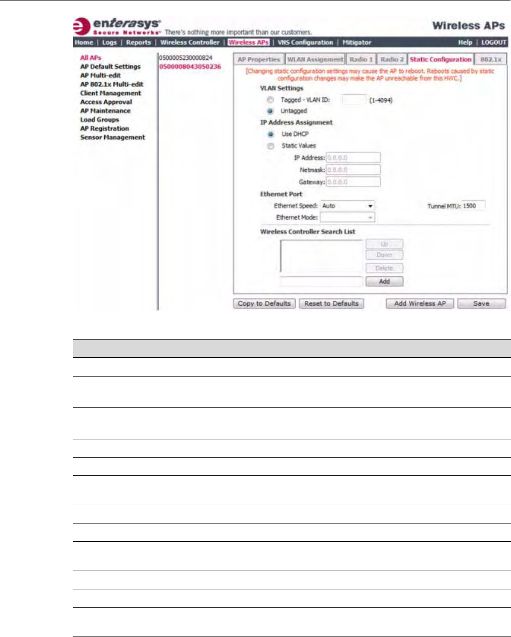
Configuring Wireless AP Settings
User Guide, V8.01 3-63
Table 3-24 Static Configuration
Field/Button Description
VLAN Settings
Tagged SelectifyouwanttoassignthisAPtoaspecificVLANandtypethevalue
inthebox.
Untagged SelectifyouwantthisAPtobeuntagged.Thisoptionisselectedby
default.
VLAN ID Enter a VLAN ID. Valid values are 1 to 4094
IP Address Assignment
Use DHCP Select to enable Dynamic Host Configuration Protocol (DHCP). This option is
enabled by default.
Static Values Select to specify the IP address of the Wireless AP.
IP Address Type the IP address of the AP.
Netmask Type the appropriate subnet mask to separate the network portion from the host
portion of the address.
Gateway Type the default gateway of the network.
Ethernet Port
Ethernet Speed If the Wireless AP has an Ethernet port, select values in the Ethernet Speed and
Ethernet Mode drop down lists.
Ethernet Mode If the Wireless AP has an Ethernet port, select values in the Ethernet Speed and
Ethernet Mode drop down lists.
DRAFT

Configuring Wireless AP Settings
3-64 Configuring the Wireless AP
Configuring Telnet/SSH Access
Telnetisusedforaccessinglegacy(non‐11n)AccessPoints.SSHisusedforaccessingNext‐
Generation(11n)AccessPoints.
ToenableordisabletelnetorSSHaccess:
1. Fromthetopmenu,clickWirelessAPs.TheWirelessAPsscreenisdisplayed.
2. IntheWirelessAPlist,clicktheWirelessAPforwhichyouwanttoenableordisabletelnet.
3. ClickAdvanced.TheAdvanceddialogisdisplayed.
Tunnel MTU Enter a static MTU value, from 600 to 1500, in the Tunnel MTU box. If the
Enterasys wireless software cannot discover the MTU size, it enforces the static
MTU size. Set the MTU size to allow the source to reduce the packet size and
avoid the need to fragment data packets in the tunnel.
Wireless Controller Search List
Up Select a controller and click the Up button to modify the order of the controllers.
When an AP searches for a controller to register with, it begins with the first
controller in the list.
Down Select a controller and click the Up button to modify the order of the controllers.
When an AP searches for a controller to register with, it begins with the first
controller in the list.
Delete Click to remove the controller from the list so that it can no longer control the
wireless AP.
Add In the Add box, type the IP address of the Enterasys Wireless Controller that will
control this Wireless AP then click the Add button to add the IP address is added
to the list. Repeat this process to add the IP addresses of up to three controllers.
This feature allows the Wireless AP to bypass the discovery process. If the
Wireless Controller Search List box is not populated, the Wireless AP will use
SLP unicast/multicast, DNS, or DHCP vendor option 43 to discover a Enterasys
Wireless Controller.
For the initial Wireless AP deployment, it is necessary to use one of the described
options in “Discovery and Registration Overview” on page 3-10.
Additional Buttons
Copy to Defaults To make this Wireless AP’s configuration be the system’s default AP settings,
click Copy to Defaults. A pop-up dialog asking you to confirm the configuration
change is displayed.To confirm resetting the system’s default Wireless AP
settings, click OK.
Reset to Defaults If you have a Wireless AP that is already configured with its own settings, but
would like the Wireless AP to be reset to use the system’s default AP settings,
use the Reset to Defaults feature
Add Wireless AP Click to manually add and register a Wireless AP to the Enterasys Wireless
Controller
Save Click to save your changes.
Table 3-24 Static Configuration (continued)
Field/Button Description
Note: The new telnet/SSH access password that you set up over the controller’s user interface
overrides the default access password. The process for setting up the new password is described
below.
DRAFT
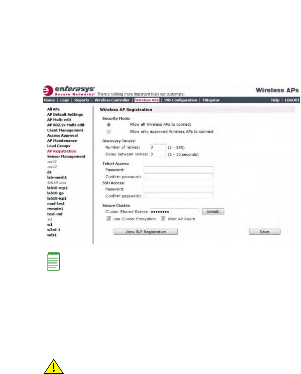
Configuring VLAN Tags for Wireless APs
User Guide, V8.01 3-65
4. IntheTelnetAccess/SSHAccessdrop‐downlist,clickoneofthefollowing:
–Enable—Enablestelnet/SSHaccess
–Disable—Disablestelnet/SSHaccess
5. Tosaveyourchanges,clickSave.
Tosetupanewtelnet/SSHaccesspassword:
1. Fromthetopmenu,clickWirelessAPs.TheWirelessAPsscreenisdisplayed.
2. Intheleftpane,clickAPRegistration.TheWirelessAPRegistrationscreenisdisplayed.
3. IfyouaresettingupanewtelnetaccesspasswordforeithertheWirelessAPorWireless
OutdoorAP,typethenewpasswordinthePasswordboxundertheTelnetAccesssection.If
youaresettingupanewSSHaccesspasswordfortheWireless802.11nAP,typethenew
passwordinthePasswordboxundertheSSHAccesssection.
4. IntheConfirmPasswordbox,re‐typethepassword.
5. Tosaveyourchanges,clickSave.
Configuring VLAN Tags for Wireless APs
ToconfiguretheVLANtagfortheWirelessAP,youmustconnecttheWirelessAPtoapointon
thecentralofficenetworkthatdoesnotrequireVLANtagging.IftheVLANtaggingisconfigured
correctlyandyouarestillonthecentralofficenetwork,theWirelessAPwillloseconnectionwith
Note: The SSH Access section on the AP Registration screen is applicable to the 11n Wireless
APs. The Telnet Access section is applicable to the Standard Wireless AP or the Enterasys
Wireless Outdoor AP.
Caution: You must exercise caution while configuring a VLAN ID tag. If a VLAN tag is not
configured properly, the connectivity between the Enterasys Wireless Controller and the Wireless
AP will be lost.
DRAFT

Configuring VLAN Tags for Wireless APs
3-66 Configuring the Wireless AP
theEnterasysWirelessControllerafteritisrebooted(theWirelessAPrebootswhenthe
configurationsettingsaresaved).
IftheWirelessAPdoesnotloseitsconnectionwiththeEnterasysWirelessControllerafterthe
reboot,theVLANIDhasnotbeenconfiguredcorrectly.AftertheVLANisconfiguredcorrectly,
youcanmovetheWirelessAPtothetargetlocation.
To Configure Wireless APs with a VLAN Tag:
1. ConnecttheWirelessAPinthecentralofficetotheEnterasysWirelessControllerport(ortoa
networkpoint)thatdoesnotrequireVLANtagging.
2. Fromthetopmenu,clickWirelessAPs.TheWirelessAPsscreenisdisplayed.
3. ClicktheStaticConfigurationtab.
4. IntheVLANSettingssection,selectTagged‐VLANID.
5. IntheTagged‐VLANIDtextbox,typetheVLANIDonwhichtheWirelessAPwilloperate.
6. Tosaveyourchanges,clickSave.TheWirelessAPrebootsandlosesconnectionwiththe
EnterasysWirelessController.
7. LogoutfromtheEnterasysWirelessController.
8. DisconnecttheWirelessAPfromthecentralofficenetworkandmoveittothetargetlocation.
9. PoweruptheWirelessAP.TheWirelessAPconnectstotheEnterasysWirelessController.
IftheWirelessAPdoesnotconnecttotheEnterasysWirelessController,theWirelessAPwas
notconfiguredproperly.Torecoverfromthissituation,youmustresettheWirelessAPtoits
factorydefaultsettings,andreconfigurethestaticIPaddress.Formoreinformation,seethe
EnterasysWirelessConvergenceSoftwareUserGuide.
Setting Up 802.1x Authentication for a Wireless AP
802.1xisanauthenticationstandardforwiredandwirelessLANs.The802.1xstandardcanbe
usedtoauthenticateaccesspointstotheLANtowhichtheyareconnected.802.1xsupport
providessecurityfornetworkdeploymentswhereaccesspointsareplacedinpublicspaces.
Tosuccessfullysetup802.1xauthenticationofaWirelessAP,theWirelessAPmustbeconfigured
for802.1xauthenticationbeforetheWirelessAPisconnectedtoa802.1xenabledswitchport.
802.1xauthenticationcredentialscanbeupdatedatanytime,whetherornottheWirelessAPis
connectedwithanactivesession.IftheWirelessAPisconnected,thenewcredentialsaresent
immediately.IftheWirelessAPisnotconnected,thenewcredentialsaredeliveredthenexttime
theWirelessAPconnectstotheEnterasysWirelessController.
Therearetwomainaspectstothe802.1xfeature:
•Credentialmanagement—TheEnterasysWirelessControllerandtheWirelessAPare
responsiblefortherequesting,creating,deleting,orinvalidatingthecredentialsusedinthe
authenticationprocess.
• Authentication—TheWirelessAPisresponsiblefortheactualexecutionoftheEAP‐TLSor
PEAPprotocol.
802.1xauthenticationcanbeconfiguredonaper‐APbasis.Forexample,802.1xauthenticationcan
beappliedtospecificWirelessAPsindividuallyorwithamulti‐editfunction.
Caution: If the switch port to which the Wireless AP is connected is not 802.1x enabled, the 802.1x
authentication will not take effect.
DRAFT

Configuring VLAN Tags for Wireless APs
User Guide, V8.01 3-67
The802.1xauthenticationsupportstwoauthenticationmethods:
•PEAP(ProtectedExtensibleAuthenticationProtocol)
–Istherecommended802.1xauthenticationmethod
–Requiresminimalconfigurationeffortandprovidesequalauthenticationprotectionto
EAP‐TLS
–UsesuserIDandpasswordsforauthenticationofaccesspoints
•EAP‐TLS
–Requiresmoreconfigurationeffort
–Requirestheuseofathird‐partyCertificateAuthenticationapplication
–Usescertificatesforauthenticationofaccesspoints
–EnterasysWirelessControllercanoperateineitherproxymodeorpassthroughmode.
‐Proxymode—TheEnterasysWirelessControllergeneratesthepublicandprivate
keypairusedinthecertificate.
‐Passthroughmode—Thecertificateandprivatekeyiscreatedbythethird‐party
CertificateAuthenticationapplication.
Configuring 802.1x PEAP Authentication
PEAPauthenticationusesuserIDandpasswordsforauthentication.Tosuccessfullyconfigure
802.1xauthenticationofaWirelessAP,theWirelessAPmustfirstbeconfiguredfor802.1x
authenticationbeforetheWirelessAPisdeployedona802.1xenabledswitchport.
To Configure 802.1x PEAP Authentication:
1. Fromthetopmenu,clickWirelessAPs.TheEnterasysWirelessAPscreendisplays.
2. IntheWirelessAPlist,clicktheWirelessAPforwhichyouwanttoconfigure802.1xPEAP
authentication.
PNote: Although a Wireless AP can support using both PEAP and EAP-TLS credentials
simultaneously, it is not recommended to do so. Instead, Enterasys recommends that you use only
one type of authentication and that you install the credentials for only that type of authentication on
the Wireless AP.
DRAFT
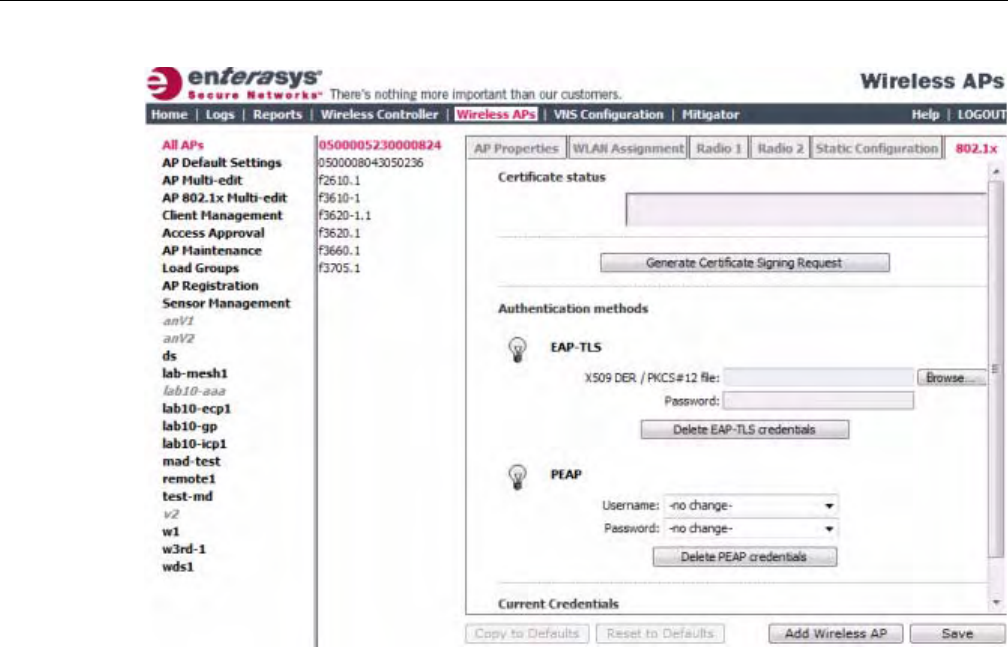
Configuring VLAN Tags for Wireless APs
3-68 Configuring the Wireless AP
3. Clickthe802.1xtab.
4. IntheUsernamedrop‐downlist,clickthevalueyouwanttoassignastheusername
credential:
–Name—ThenameoftheWirelessAP,whichisassignedontheAPPropertiestab.The
WirelessAPnamecanbeedited.
–Serial—TheserialnumberoftheWirelessAP.Thissettingcannotbeedited.
–MAC—TheMACaddressoftheWirelessAP.Thesettingcannotbeedited.
–Other—Clicktospecifyacustomvalue.Atextboxisdisplayed.Inthetextbox,typethe
valueyouwanttoassignastheusernamecredential.
5. InthePassworddrop‐downlist,clickthevalueyouwanttoassignasthepasswordcredential:
–Name—ThenameoftheWirelessAP,whichisassignedontheAPPropertiestab.The
WirelessAPnamecanbeedited.
–Serial—TheserialnumberoftheWirelessAP.Thesettingcannotbeedited.
–MAC—TheMACaddressoftheWirelessAP.Thesettingcannotbeedited.
–Other—Clicktospecifyacustomvalue.Atextboxisdisplayed.Inthetextbox,typethe
valueyouwanttoassignasthepasswordcredential.
6. Tosaveyourchanges,clickSave.
The802.1xPEAPauthenticationconfigurationisassignedtotheWirelessAP.TheWirelessAP
cannowbedeployedtoa802.1xenabledswitchport.
DRAFT
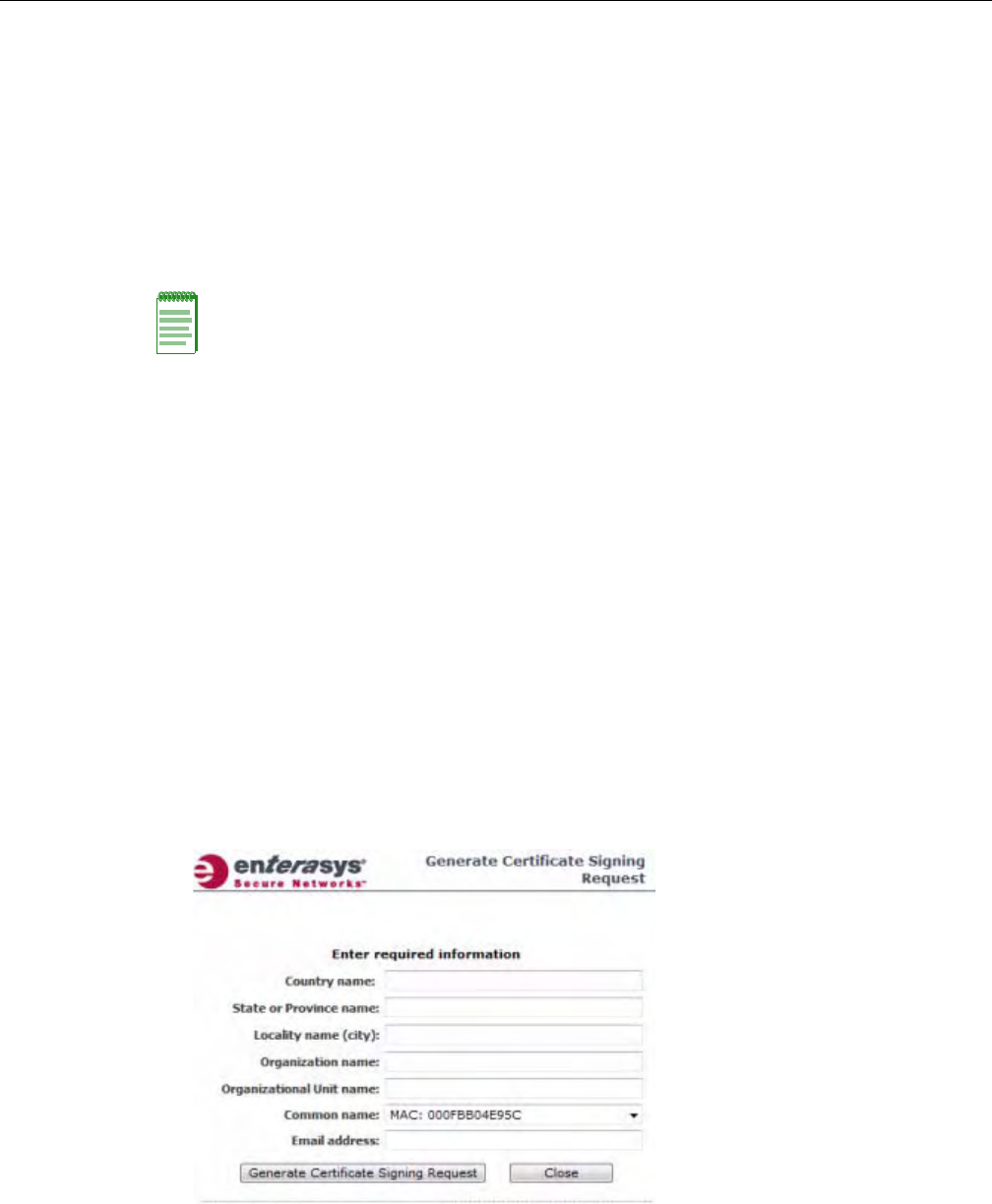
Configuring VLAN Tags for Wireless APs
User Guide, V8.01 3-69
Configuring 802.1x EAP-TLS Authentication
EAP‐TLSauthenticationusescertificatesforauthentication.Athird‐partyCertificate
AuthenticationapplicationisrequiredtoconfigureEAP‐TLSauthentication.Certificatescanbe
overwrittenwithnewonesatanytime.
WithEAP‐TLSauthentication,theEnterasysWirelessControllercanoperateinthefollowing
modes:
•ProxyMode
•PassThroughMode
Proxy Mode
Inproxymode,EnterasysWirelessControllergeneratesthepublicandprivatekeypairusedin
thecertificate.YoucanspecifythecriteriausedtocreatetheCertificateRequest.TheCertificate
RequestthatisgeneratedbytheEnterasysWirelessControlleristhenusedbythethird‐party
CertificateAuthenticationapplicationtocreatethecertificateusedforauthenticationofthe
WirelessAP.Tosuccessfullyconfigure802.1xauthenticationofaWirelessAP,theWirelessAP
mustfirstbeconfiguredfor802.1xauthenticationbeforetheWirelessAPisdeployedona802.1x
enabledswitchport.
To Configure 802.1x EAP-TLS Authentication in Proxy Mode:
1. Fromthetopmenu,clickWirelessAPs.TheWirelessAPscreenisdisplayed.
2. IntheWirelessAPlist,clicktheWirelessAPforwhichyouwanttoconfigure802.1xEAP‐TLS
authentication.
3. Clickthe802.1xtab.
4. ClickGenerateCertificateSigningRequest.TheGenerateCertificateSigningRequest
windowisdisplayed.
5. Typethecriteriatobeusedtocreatethecertificaterequest.Allfieldsarerequired:
–Countryname—Thetwo‐letterISOabbreviationofthenameofthecountry
–StateorProvincename—ThenameoftheState/Province
Note: When a Wireless AP configured with 802.1x EAP-TLS authentication is connected to a
Enterasys Wireless Controller, the Wireless AP begins submitting logs to the Enterasys Wireless
Controller thirty days before the certificate expires to provide administrators with a warning of the
impending expiry date.
DRAFT

Configuring VLAN Tags for Wireless APs
3-70 Configuring the Wireless AP
–Localityname(city)—Thenameofthecity
–Organizationname—Thenameoftheorganization
–OrganizationalUnitname—Thenameoftheunitwithintheorganization
–Commonname—Clickthevalueyouwanttoassignasthecommonnameofthe
WirelessAP:
‐Name—ThenameoftheWirelessAP,whichisassignedontheAPPropertiestab.
TheWirelessAPnamecanbeedited.
‐Serial—TheserialnumberoftheWirelessAP.Thesettingcannotbeedited.
‐MAC—TheMACaddressoftheWirelessAP.Thesettingcannotbeedited.
‐Other—Clicktospecifyacustomvalue.Atextboxisdisplayed.Inthetextbox,type
thevalueyouwanttoassignasthecommonnameoftheWirelessAP.
–Emailaddress—Theemailaddressoftheorganization
6. ClickGenerateCertificateSigningRequest.Acertificaterequestfileisgenerated(.csrfile
extension).ThenameofthefileistheWirelessAPserialnumber.TheFileDownloaddialogis
displayed.
7. ClickSave.TheSaveaswindowisdisplayed.
8. Navigatetothelocationonyourcomputerthatyouwanttosavethegeneratedcertificate
requestfile,andthenclickSave.
9. Inthethird‐partyCertificateAuthenticationapplication,usethecontentofthegenerated
certificaterequestfiletogeneratethecertificatefile(.cerfileextension).
10. Onthe802.1xtab,clickBrowse.TheChoosefilewindowisdisplayed.
11. Navigatetothelocationofthecertificatefile,andclickOpen.Thenameofthecertificatefileis
displayedintheX509DER/PKCS#12filebox.
12. Tosaveyourchanges,clickSave.
The802.1xEAP‐TLS(certificateandprivatekey)authenticationinproxymodeisassignedto
theWirelessAP.TheWirelessAPcannowbedeployedtoa802.1xenabledswitchport.
Pass Through Mode
Inpassthroughmode,thecertificateandprivatekeyarecreatedbythethird‐partyCertificate
Authenticationapplication.Tosuccessfullyconfigure802.1xauthenticationofaWirelessAP,the
WirelessAPmustfirstbeconfiguredfor802.1xauthenticationbeforetheWirelessAPisdeployed
ona802.1xenabledswitchport.
Beforeyouconfigure802.1xusingEAP‐TLSauthenticationinpassthroughmode,youmustfirst
createacertificateusingthethird‐partyCertificateAuthenticationapplicationandsavethe
certificatefileinPKCS#12fileformat(.pfxfileextension)onyoursystem.
To Configure 802.1x EAP-TLS Authentication in Pass Through Mode:
1. Fromthetopmenu,clickWirelessAPs.TheWirelessAPscreenisdisplayed.
2. IntheWirelessAPlist,clicktheWirelessAPforwhichyouwanttoconfigure802.1xEAP‐TLS
authentication.
3. Clickthe802.1xtab.
4. ClickBrowse.TheChoosefilewindowisdisplayed.
5. Navigatetothelocationofthecertificatefile(.pfx)andclickOpen.Thenameofthecertificate
fileisdisplayedintheX509DER/PKCS#12filebox.
DRAFT

Configuring VLAN Tags for Wireless APs
User Guide, V8.01 3-71
6. InthePasswordbox,typethepasswordthatwasusedtoprotecttheprivatekey.
7. Tosaveyourchanges,clickSave.
The802.1xEAP‐TLSauthenticationinpassthroughmodeisassignedtotheWirelessAP.The
WirelessAPcannowbedeployedtoa802.1xenabledswitchport.
Viewing 802.1x Credentials
When802.1xauthenticationisconfiguredonaWirelessAP,thelightbulbicononthe802.1xtab
fortheconfiguredWirelessAPislittoindicatewhich802.1xauthenticationmethodisused.A
WirelessAPcanbeconfiguredtousebothEAP‐TLSandPEAPauthenticationmethods.For
example,whenbothEAP‐TLSandPEAPauthenticationmethodsareconfiguredfortheWireless
AP,bothlightbulbiconsonthe802.1xtabarelit.
To View Current 802.1x Credentials:
1. Fromthetopmenu,clickWirelessAPs.TheWirelessAPscreenisdisplayed.
2. IntheWirelessAPlist,clicktheWirelessAPforwhichyouwanttoviewitscurrent802.1x
credentials.
3. Selectthe802.1xtab.
Note: The password that was used to protect the private key must be a maximum of 31 characters
long.
Note: You can only view the 802.1x credentials of Wireless APs that have an active session with
the Enterasys Wireless Controller. If you attempt to view the credentials of a Wireless AP that does
not have an active session, the Wireless AP Credentials window displays the following message:
Unable to query Wireless AP: not connected.
DRAFT
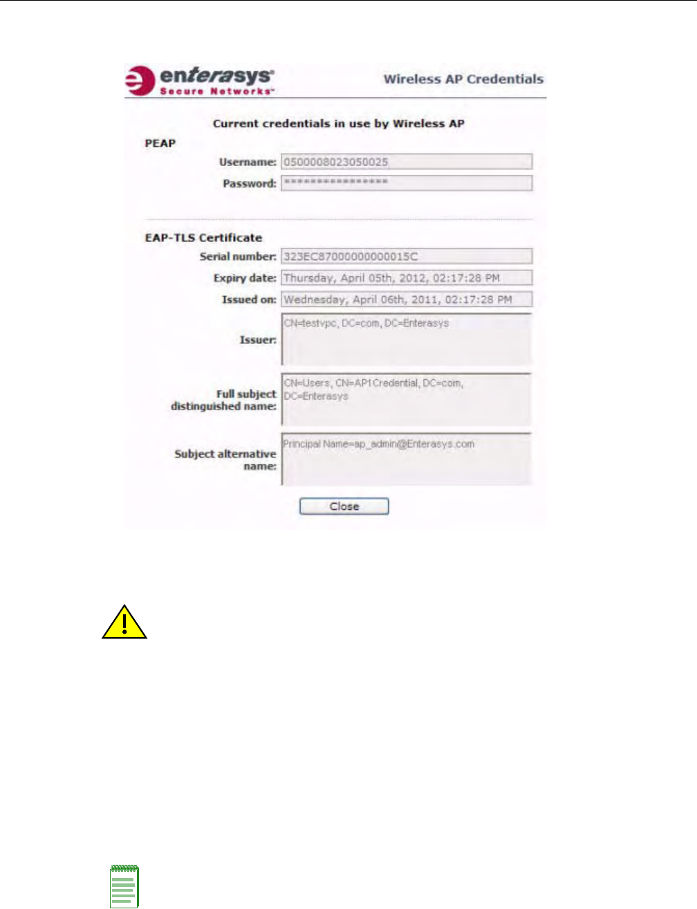
Configuring VLAN Tags for Wireless APs
3-72 Configuring the Wireless AP
4. IntheCurrentCredentialssection,clickGetCertificatedetails.TheWirelessAPCredentials
windowisdisplayed.
Deleting 802.1x Credentials
To Delete Current 802.1x Credentials:
1. Fromthetopmenu,clickWirelessAPs.TheWirelessAPscreenisdisplayed.
2. IntheWirelessAPlist,clicktheWirelessAPforwhichyouwanttodeleteitscurrent802.1x
credentials.
3. Dothefollowing:
–TodeleteEAP‐TLScredentials,clickDeleteEAP‐TLScredentials.
–TodeletePEAPcredentials,clickDeletePEAPcredentials.
ThecredentialsaredeletedandtheWirelessAPsettingsareupdated.
Caution: Exercise caution when deleting 802.1x credentials. For example, deleting 802.1x
credentials may prevent the Wireless AP from being authenticated or cause it to lose its connection
with the Enterasys Wireless Controller.
Note: If you attempt to delete the 802.1x credentials of a Wireless AP that currently does not have
an active session with the Enterasys Wireless Controller, the credentials are only deleted after the
Wireless AP connects with the Enterasys Wireless Controller.
DRAFT
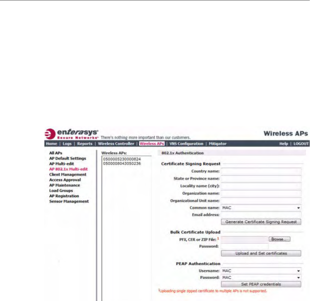
Configuring VLAN Tags for Wireless APs
User Guide, V8.01 3-73
Setting Up 802.1x Authentication for Wireless APs Using Multi-edit
InadditiontoconfiguringWirelessAPsindividually,youcanalsoconfigure802.1xauthentication
formultipleWirelessAPssimultaneouslybyusingtheAP802.1xMulti‐editfeature.
WhenyouusetheAP802.1xMulti‐editfeature,youcanchooseto:
• AssignEAP‐TLSauthenticationbasedongeneratedcertificatestomultipleWirelessAPsby
uploadinga.pfx,.cer,or.zipfile.
• AssignPEAPcredentialstomultipleWirelessAPsbasedonausernameandpasswordthat
youdefine
To Configure 802.1x EAP-TLS Authentication in Proxy Mode Using Multi-edit:
1. Fromthetopmenu,clickWirelessAPs.TheWirelessAPscreenisdisplayed.
2. Intheleftpane,clickAP802.1xMulti‐edit.
3. IntheWirelessAPslist,clickoneormoreWirelessAPstoconfigure.Toselectmultiple
WirelessAPs,clicktheWirelessAPsfromthelistwhilepressingtheCTRLkey.
4. IntheCertificateSigningRequestsection,typethefollowing:
–Countryname—Thetwo‐letterISOabbreviationofthenameofthecountry
–StateorProvincename—ThenameoftheState/Province
–Localityname(city)—Thenameofthecity
–Organizationname—Thenameoftheorganization
–OrganizationalUnitname—Thenameoftheunitwithintheorganization
DRAFT

Configuring VLAN Tags for Wireless APs
3-74 Configuring the Wireless AP
–Commonname—Clickthevalueyouwanttoassignasthecommonnameofthe
WirelessAP:
‐Name—ThenameoftheWirelessAP,whichisassignedontheAPPropertiestab.
TheWirelessAPnamecanbeedited.
‐Serial—TheserialnumberoftheWirelessAP.TheWirelessAPserialnumbercannot
beedited.
‐MAC—TheMACaddressoftheWirelessAP.TheWirelessAPMACaddresscannot
beedited.
–Emailaddress—Theemailaddressoftheorganization
5. ClickGenerateCertificates.TheAP802.1xMulti‐editprogresswindowisdisplayed,which
providesthestatusoftheconfigurationprocess.Oncecomplete,theFileDownloaddialogis
displayed.
6. ClickSave.TheSaveaswindowisdisplayed.
7. Navigatetothelocationonyourcomputerthatyouwanttosavethegenerated
certificate_requests.tarfile,andthenclickSave.
Thecertificate_requests.tarfilecontainsacertificaterequest(.csr)fileforeachWirelessAP.
8. Dooneofthefollowing:
–Foreachcertificaterequest,generateacertificateusingthethird‐partyCertificate
Authenticationapplication.ThismethodwillproduceacertificateforeachWirelessAP.
Oncecomplete,zipallthecertificatesfiles(.cer)intoone.zipfile.
–UseoneofthecertificaterequestsandgenerateonecertificateusingtheCertificate
Authenticationapplication.Thismethodwillproduceonecertificatethatcanbeapplied
toallWirelessAPs.
9. IntheBulkCertificateUploadsection,clickBrowse.TheChoosefilewindowisdisplayed.
10. Navigatetothelocationofthefile(.zipor.cer),andthenclickOpen.Thenameofthefileis
displayedinthePFX,CERorZIPArchivebox.
11. ClickUploadandSetcertificates.Oncecomplete,theSettingsupdatedmessageisdisplayed
inthefooteroftheEnterasysWirelessAssistant.
The802.1xEAP‐TLSauthenticationconfigurationisassignedtotheWirelessAPs.The
WirelessAPscannowbedeployedto802.1xenabledswitchports.
Configuring 802.1x EAP-TLS Authentication in Pass Through Mode Using Multi-
edit:
Whenyouconfigure802.1xEAP‐TLSauthenticationinpassthroughmodeusingMulti‐edit,do
oneofthefollowing:
•GenerateacertificateforeachWirelessAPusingthethird‐partyCertificateAuthentication
application.Whengeneratingthecertificates:
–UsetheCommonnamevalue(eitherName,Serial,orMAC)oftheWirelessAPtoname
eachgeneratedcertificate.
–U
seacommonpasswordforeachgeneratedcertificate.
–All.pfxfilescreatedbythethird‐partyCertificateAuthenticationapplicationmustbe
zippedintoonefile.
•Generateonecertificate,usingthethird‐partyCertificateAuthenticationapplication,tobe
appliedtoallWirelessAPs.Whengeneratingthecertificate,usetheCommonnamevalue
(eitherName,Serial,orMAC)oftheWirelessAPtonamethegeneratedcertificate.
DRAFT

Configuring VLAN Tags for Wireless APs
User Guide, V8.01 3-75
To Configure 802.1x EAP-TLS Authentication in Pass Through Mode Using Multi-
edit:
1. Fromthetopmenu,clickWirelessAPs.TheWirelessAPscreenisdisplayed.
2. Intheleftpane,clickAP802.1xMulti‐edit.
3. IntheWirelessAPslist,clickoneormoreWirelessAPstoconfigure.Toselectmultiple
WirelessAPs,clicktheWirelessAPsfromthelistwhilepressingtheCTRLkey.
4. IntheBulkCertificateUploadsection,clickBrowse.TheChoosefilewindowisdisplayed.
5. Navigatetothelocationofthefile(.zipor.pfx),andthenclickOpen.Thenameofthefileis
displayedinthePFX,CERorZIPArchivebox.
6. InthePasswordbox,typethepasswordusedduringthecertificatesgenerationprocess.
7. ClickUploadandSetcertificates.Oncecomplete,theSettingsupdatedmessageisdisplayed
inthefooteroftheEnterasysWirelessAssistant.
The802.1xEAP‐TLSauthenticationconfigurationisassignedtotheWirelessAPs.The
WirelessAPscannowbedeployedto802.1xenabledswitchports.
To Configure 802.1x PEAP Authentication Using Multi-edit:
1. Fromthetopmenu,clickWirelessAPConfiguration.TheWirelessAPscreenisdisplayed.
2. Intheleftpane,clickAP802.1xMulti‐edit.
3. IntheWirelessAPslist,clickoneormoreAPstoedit.ToselectmultipleAPs,clicktheAPs
fromthelistwhilepressingtheCTRLkey.
4. InthePEAPAuthenticationsection,dothefollowing:
–IntheUsernamedrop‐downlist,clickthevalueyouwanttoassignastheusername
credential:
‐Name—ThenameoftheWirelessAP,whichisassignedontheAPPropertiestab.
TheWirelessAPnamecanbeedited.
‐Serial—TheserialnumberoftheWirelessAP.TheWirelessAPserialnumbercannot
beedited.
‐MAC—TheMACaddressoftheWirelessAP.TheWirelessAPMACaddresscannot
beedited.
–InthePassworddrop‐downlist,clickthevalueyouwanttoassignasthepassword
credential:
‐Name—ThenameoftheWirelessAP,whichisassignedontheAPPropertiestab.
TheWirelessAPnamecanbeedited.
‐Serial—TheserialnumberoftheWirelessAP.TheWirelessAPserialnumbercannot
beedited.
‐MAC—TheMACaddressoftheWirelessAP.TheWirelessAPMACaddresscannot
beedited.
5. ClickSetPEAPcredentials.TheAP802.1xMulti‐editprogresswindowisdisplayed,which
providesthestatusoftheconfigurationprocess.Oncecomplete,theSettingsupdated
messageisdisplayedinthefooteroftheEnterasysWirelessAssistant.
The802.1xPEAPauthenticationconfigurationisassignedtotheWirelessAPs.TheWireless
APscannowbedeployedto802.1xenabledswitchports.
DRAFT

Configuring VLAN Tags for Wireless APs
3-76 Configuring the Wireless AP
Configuring the Default Wireless AP Settings
WirelessAPsareaddedwithdefaultsettings.Youcanmodifythesystem’sWirelessAPdefault
settings,andthenusethesedefaultsettingstoconfigurenewlyaddedWirelessAPs.Inaddition,
youcanbasethesystem’sWirelessAPdefaultsettingsonanexistingWirelessAPconfigurationor
youcanhaveconfiguredWirelessAPsinheritthepropertiesofthedefaultWirelessAP
configurationwhentheyregisterwiththesystem.
TheprocessofconfiguringthedefaultWirelessAPsettingsisdividedintouptosixtabs:
•CommonConfiguration—Configurecommonconfiguration,suchasWLANassignments
andstaticconfigurationoptionsforallWirelessAPs.See“ConfigureCommonConfiguration
DefaultAPSettings”onpage 3‐76.
•AP2610AP2620AP2605W788BP200WB500—Configurethedefaultsettingsforthe
standardWirelessAPs,andtheW788,BP200,andWB500accesspoints.See“Configure
AP2610/20,AP2605,W788,BP200,andWB500DefaultAPSettings”onpage 3‐77.
•AP36xx—ConfigurethedefaultsettingsfortheWireless802.11nAPs.See“Configure
AP36xxDefaultAPSettings”onpage 3‐83.
•AP2650AP2660W786—ConfigurethedefaultsettingsfortheEnterasysWirelessOutdoor
APsandtheW786accesspoints.See“ConfigureAP2650/60,W786DefaultAPSettings”on
page 3‐89.
• AP4102x—ConfigurethedefaultsettingsfortheAP4102andtheAP4102Caccesspoints.See
“ConfigureAP4102xDefaultAPSettings”onpage 3‐95.
•AP37xxW78xC—ConfigurethedefaultsettingsfortheWireless802.11nAPs.See“Configure
AP37xx,W78xCDefaultAPSettings”onpage 3‐101.
Configure Common Configuration Default AP Settings
To Configure Common Configuration Default AP Settings:
1. Fromthetopmenu,clickWirelessAPs.TheWirelessAPscreenisdisplayed.
DRAFT
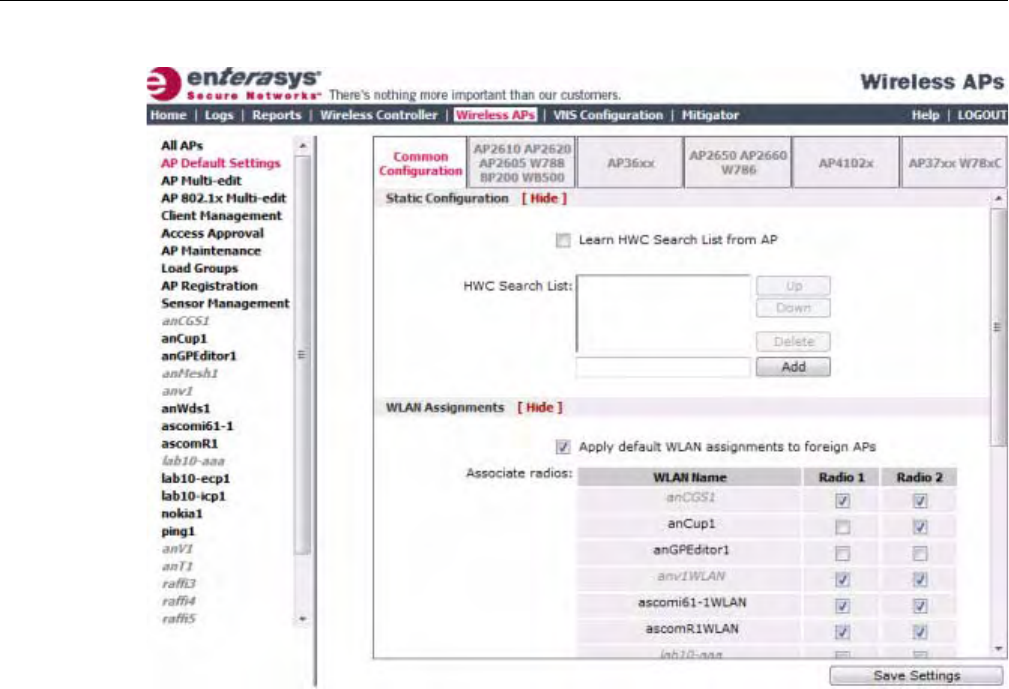
Configuring VLAN Tags for Wireless APs
User Guide, V8.01 3-77
2. Intheleftpane,clickAPDefaultSettings.TheCommonConfigurationtabisdisplayed.
3. IntheStaticConfigurationsection,dooneofthefollowing:
–ToalloweachWirelessAPtoprovideitsownHWCSearchList,selecttheLearnHWC
SearchListfromAPcheckbox.
–TospecifyacommonHWCSearchListforallWirelessAPs,cleartheLearnHWCSearch
ListfromAPcheckbox.
TheWirelessAPissuccessfulwhenitfindsaEnterasysWirelessControllerthatwillallowit
toregister.
ThisfeatureallowstheWirelessAPtobypassthediscoveryprocess.IftheWireless
ControllerSearchListboxisnotpopulated,theWirelessAPwilluseSLPunicast/multicast,
DNS,orDHCPvendoroption43todiscoveraEnterasysWirelessController.
TheDHCPfunctionforwirelessclientsmustbeprovidedlocallybyalocalDHCPserver,
unlesseachwirelessclienthasastaticIPaddress.
FortheinitialWirelessAPdeployment,itisnecessarytouseoneofthedescribedoptionsin
“DiscoveryandRegistrationOverview”onpage 3‐10.
4. IntheWLANAssignmentssection,assigntheRadiosforeachVNSinthelistbyselectingor
clearingtheoptionboxes.
5. Tosaveyourchanges,clickSaveSettings.
Configure AP2610/20, AP2605, W788, BP200, and WB500 Default AP Settings
To Configure AP2610/20, AP2605, W788, BP200, and WB500 Default AP Settings:
1. Fromthetopmenu,clickWirelessAPs.TheWirelessAPscreenisdisplayed.
DRAFT
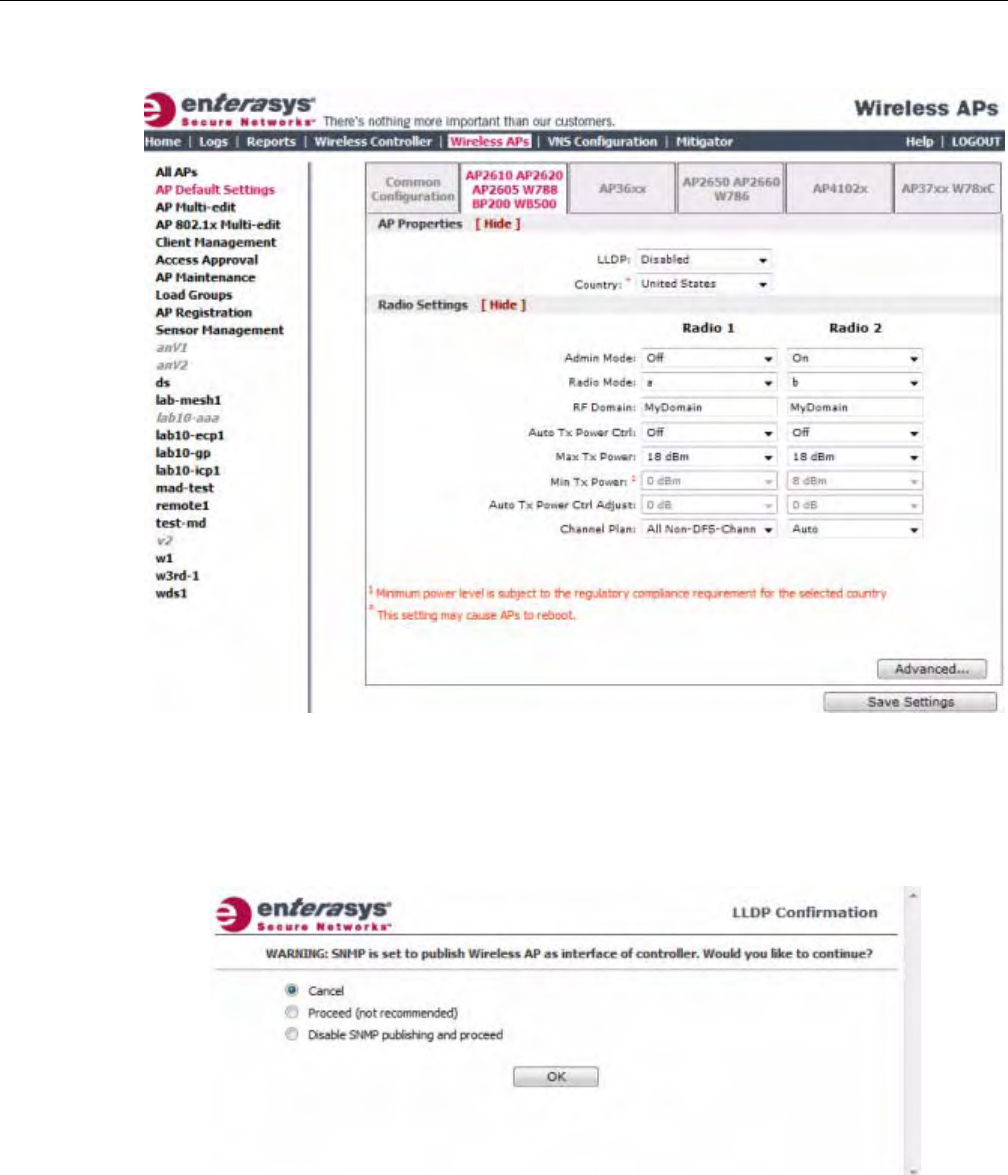
Configuring VLAN Tags for Wireless APs
3-78 Configuring the Wireless AP
2. Intheleftpane,clickAPDefaultSettings.TheCommonConfigurationtabisdisplayed.
3. ClicktheAP2610AP2620AP2605W788BP200WB500tab.
4. IntheAPPropertiessection,dothefollowing:
–LLDP—ClicktoEnableorDisabletheWirelessAPfrombroadcastingLLDP
information.Thisoptionisdisabledbydefault.
IfSNMPisenabledontheEnterasysWirelessControllerandyouenableLLDP,theLLDP
Confirmationdialogisdisplayed.
–Selectoneofthefollowing:
‐Proceed(notrecommended)—SelectthisoptiontoenableLLDPandkeepSNMP
running,andthenclickOK.
‐DisableSNMPpublishing,andproceed—SelectthisoptiontoenableLLDPand
disableSNMP,andthenclickOK.
DRAFT

Configuring VLAN Tags for Wireless APs
User Guide, V8.01 3-79
FormoreinformationonusingSNMP,seetheEnterasysWirelessConvergenceSoftware
MaintenanceGuide.
–AnnouncementInterval—IfLLDPisenabled,typehowoftentheWirelessAPadvertises
itsinformationbysendinganewLLDPpacket.Thisvalueismeasuredinseconds.
IftherearenochangestotheWirelessAPconfigurationthatimpacttheLLDP
information,theWirelessAPsendsanewLLDPpacketaccordingtothisschedule.
–AnnouncementDelay—IfLLDPisenabled,typetheannouncementdelay.Thisvalueis
measuredinseconds.IfachangetotheWirelessAPconfigurationoccurswhichimpacts
theLLDPinformation,theWirelessAPsendsanupdatedLLDPpacket.The
announcementdelayisthelengthoftimethatdelaysthenewpacketdelivery.The
announcementdelayhelpsminimizeLLDPpackettraffic.
–Country—Clickthecountryofoperation.Thisoptionisonlyavailablewithcertain
licenses.
5. IntheRadioSettingssection,dothefollowingforeachradio:
–Adminmode—SelectOntoenablethisradio;SelectOfftodisablethisradio.
–Radiomode—Clicktheradiomodeyouwanttoenable:
‐Radio1—a.
‐Radio2—b,g,orb/g.
–RFDomain—TypeastringthatuniquelyidentifiesagroupofAPsthatcooperatein
managingRFchannelsandtransmissionpowerlevels.Themaximumlengthofthestring
is16characters.TheRFDomainisusedtoidentifyagroupofWirelessAPs.
–AutoTxPowerCtrl—ClicktoeitherenableordisableATPCfromtheAutoTxPower
Ctrldrop‐downlist.ATPCautomaticallyadaptstransmissionpowersignalsaccordingto
thecoverageprovidedbytheWirelessAPs.Afteraperiodoftime,thesystemwill
stabilizeitselfbasedontheRFcoverageofyourWirelessAPs.
–MaxTxPower—ClicktheappropriateTxpowerlevelfromtheMaxTXPowerdrop‐
downlist.ThevaluesintheMaxTXPowerdrop‐downareindBm.
–MinTxPower—IfATPCisenabled,clicktheminimumTxpowerleveltowhichthe
rangeoftransmitpowercanbeadjusted:0to23(b/gorb/g/n)or24(aora/n)dBm.
Enterasysrecommendsthatyouuse0dBmifyoudonotwanttolimitthepotentialTx
powerlevelrangethatcanbeused.
–AutoTxPowerCtrlAdjust—IfATPCisenabled,clicktheTxpowerlevelthatcanbe
usedtoadjusttheATPCpowerlevelsthatthesystemhasassigned.Enterasys
recommendsthatuse0dBmduringyourinitialconfiguration.IfyouhaveanRFplanthat
recommendsTxpowerlevelsforeachWirelessAP,comparetheactualTxpowerlevels
yoursystemhasassignedagainsttherecommendedvaluesyourRFplanhasprovided.
UsetheAutoTxPowerCtrlAdjustvaluetoachievetherecommendedvalues.
–ChannelPlan—IfACSisenabledyoucandefineachannelplanfortheWirelessAP.
Definingachannelplanallowsyoutolimitwhichchannelsareavailableforuseduringan
Note: The Time to Live value cannot be directly edited. The Time to Live value is calculated as
four times the Announcement Interval value.
Note: Depending on the radio modes you select, some of the radio settings may not be available for
configuration.
DRAFT

Configuring VLAN Tags for Wireless APs
3-80 Configuring the Wireless AP
ACSscan.Forexample,youmaywanttoavoidusingspecificchannelsbecauseoflow
power,regulatorydomain,orradarinterference.
ForRadio1,clickoneofthefollowing:
‐Allchannels—ACSscansallchannelsforanoperatingchannelandreturnsboth
DFSandnon‐DFSchannels,ifavailable.
‐AllNon‐DFSChannels—ACSscansallnon‐DFSchannelsforanoperatingchannel.
ThisselectionisavailablewhenthereisatleastoneDFSchannelsupportedforthe
selectedcountry.
‐Custom—ToconfigureindividualchannelsfromwhichtheACSwillselectan
operatingchannel,clickConfigure.TheCustomChannelPlandialogdisplays.By
default,allchannelsparticipateinthechannelplan.Clicktheindividualchannelsyou
wanttoincludeinthechannelplan.Toselectcontiguouschannels,usetheShiftkey.
Toselectmultiple,non‐contiguouschannelsinthelist,usetheCTRLkey.ClickOKto
savetheconfiguration.
ForRadio2,clickoneofthefollowing:
‐3ChannelPlan—ACSwillscanthefollowingchannels:1,6,and11inNorth
America,and1,7,and13intherestoftheworld.
‐4ChannelPlan—ACSwillscanthefollowingchannels:1,4,7,and11inNorth
America,and1,5,9,and13intherestoftheworld.
‐Auto—ACSwillscanthedefaultchannelplanchannels:1,6,and11inNorth
America,and1,5,9,and13intherestoftheworld.
‐Custom—IfyouwanttoconfigureindividualchannelsfromwhichtheACSwill
selectanoperatingchannel,clickConfigure.TheAddChannelsdialogisdisplayed.
Clicktheindividualchannelsyouwanttoaddtothechannelplanwhilepressingthe
CTRLkey,andthenclickOK.
6. Tomodifydefaultaccesspointadvancedsettings,clickAdvanced.TheAdvanceddialogis
displayed.
7. IntheAdvanceddialogAPPropertiessection,dothefollowing:
–PollTimeout—Typethetimeoutvalue,inseconds.TheWirelessAPusesthisvalueto
triggerre‐establishingthelinkwiththeEnterasysWirelessControllerifit(WirelessAP)
doesnotgetananswertoitspolling.Thedefaultvalueis10seconds.
–RemoteAccess—ClicktoEnableorDisabletelnetaccesstotheWirelessAP.
–location‐basedservice—ClicktoEnableorDisablelocation‐basedserviceonthis
WirelessAP.location‐basedserviceallowsyoutousethisWirelessAPwithanAeroScout
orEkahausolution.
–Maintainclientsessionineventofpollfailure—ClicktoEnableorDisable(ifusinga
bridgedatAPVNS)iftheAPshouldremainactiveifalinklosswiththecontroller
occurs.Thisoptionisenabledbydefault.
–Restartserviceintheabsenceofcontroller—ClicktoEnableorDisable(ifusinga
bridgedatAPVNS)toensuretheWirelessAPcontinuesprovidingserviceiftheWireless
AP’sconnectiontotheEnterasysWirelessControllerislost.Ifthisoptionisenabled,it
allowstheWirelessAPtostartabridgedatAPVNSevenintheabsenceofaEnterasys
WirelessController.
Note: If you are configuring session availability, the Poll Timeout value should be 1.5 to 2 times of
Detect link failure value on AP Properties screen. For more information, see “Session Availability”
on page 11-9.
DRAFT

Configuring VLAN Tags for Wireless APs
User Guide, V8.01 3-81
–Usebroadcastfordisassociation—ClicktoEnableorDisableifyouwanttheWireless
APtousebroadcastdisassociationwhendisconnectingallclients,insteadof
disassociatingeachclientonebyone.ThiswillaffectthebehavioroftheAPunderthe
followingconditions:
‐IftheWirelessAPispreparingtorebootortoenteroneofthespecialmodes(DRM
initialchannelselection).
‐IfaBSSIDisdeactivatedorremovedontheWirelessAP.
Thisoptionisdisabledbydefault.
8. IntheAdvanceddialogRadioSettingssection,dothefollowing:
–DTIM—TypethedesiredDTIM(DeliveryTrafficIndicationMessage)period—the
numberofbeaconintervalsbetweentwoDTIMbeacons.Toensurethebestclientpower
savings,usealargenumber.Forexample,5.Useasmallnumbertominimizebroadcast
andmulticastdelay.Thedefaultvalueis5.
–BeaconPeriod—Typethedesiredtime,inmilliseconds,betweenbeacontransmissions.
Thedefaultvalueis100milliseconds.
–RTS/CTS—Typethepacketsizethreshold,inbytes,abovewhichthepacketwillbe
precededbyanRTS/CTS(RequesttoSend/CleartoSend)handshake.Thedefaultvalueis
2346,whichmeansallpacketsaresentwithoutRTS/CTS.Reducethisvalueonlyif
necessary.
–Frag.Threshold—Typethefragmentsizethreshold,inbytes,abovewhichthepackets
willbefragmentedbytheAPpriortotransmission.Thedefaultvalueis2346,which
meansallpacketsaresentunfragmented.
–Max%ofnon‐unicasttrafficperBeaconperiod—Enterthemaximumpercentageof
timethattheAPwilltransmitnon‐unicastpackets(broadcastandmulticasttraffic)for
eachconfiguredBeaconPeriod.Foreachnon‐unicastpackettransmitted,thesystem
calculatestheairtimeusedbyeachpacketanddropsallpacketsthatexceedthe
configuredmaximumpercentage.Byrestrictingnon‐unicasttraffic,youlimittheimpact
ofbroadcastsandmulticastsonoverallsystemperformance.
–MaximumDistance—Enteravaluefrom100to15,000metersthatidentifiesthe
maximumlinkdistancebetweenAPsthatparticipateinaWDS.Thisvalueensuresthat
theacknowledgementofcommunicationbetweenAPsdoesnotexceedthetimeoutvalue
predefinedbythe802.11standard.Thedefaultvalueis100meters.Ifthelinkdistance
betweenAPsisgreaterthan100meters,configurethemaximumdistanceupto15,000
meterssothatthesoftwareincreasesthetimeoutvalueproportionallywiththedistance
betweenAPs.
Donotchangethedefaultsettingfortheradiothatprovidesserviceto802.11clientsonly.
–DynamicChannelSelection—Clickoneofthefollowing:
‐Off—DisablesDCS.
‐MonitorMode—IftrafficornoiselevelsexceedtheconfiguredDCSthresholds,an
alarmistriggeredandaninformationlogisgenerated.
‐ActiveMode—IftrafficornoiselevelsexceedtheconfiguredDCSthresholds,an
alarmistriggeredandaninformationlogisgenerated.Inaddition,theWirelessAP
willceaseoperatingonthecurrentchannelandACSisemployedtoautomatically
selectanalternatechannelfortheWirelessAPtooperateon.
‐DCSNoiseThreshold—IfDCSisenabled,typethenoiseinterferencelevel,
measuredindBm,afterwhichACSwillscanforanewoperatingchannelforthe
WirelessAPifthethresholdisexceeded.
DRAFT

Configuring VLAN Tags for Wireless APs
3-82 Configuring the Wireless AP
‐DCSChannelOccupancyThreshold—IfDCSisenabled,typethechannel
utilizationlevel,measuredasapercentage,afterwhichACSwillscanforanew
operatingchannelfortheWirelessAPifthethresholdisexceeded.
‐DCSUpdatePeriod—IfDCSisenabled,typethetime,measuredinminutesthat
determinestheperiodduringwhichtheWirelessAPaveragestheDCSNoise
ThresholdandDCSChannelOccupancyThresholdmeasurements.Ifeitheroneof
thesethresholdsisexceeded,thentheWirelessAPwilltriggerACS.
–RxDiversity—ClickBestforthebestsignalfrombothantennas,orLeftorRightto
chooseeitherofthetwodiversityreceivingantennas.Thedefaultandrecommended
selectionisBest.Ifonlyoneantennaisconnected,usethecorrespondingLeftorRight
diversitysetting.DonotuseBestiftwoidenticalantennasarenotused.
–TxDiversity—ClickAlternateforthebestsignalfrombothantennas,orLeftorRightto
chooseeitherofthetwodiversityreceivingantennas.ThedefaultselectionisAlternate
thatmaximizesperformanceformostclients.However,someclientsmaybehaveoddly
withTxDiversitysettoAlternate.Underthosecircumstances,Enterasysrecommends
thatyouuseeitherLeftorRightforTxDiversity.Ifonlyoneantennaisconnected,usethe
correspondingLeftorRightdiversitysetting.DonotuseAlternateiftwoidentical
antennasarenotused.
–Preamble—Clickapreambletypefor11b‐specific(CCK)rates:Short,Long,orAuto.The
recommendedvalueisAuto.ClickShortifyouaresurethatthereisnopre‐11bAPora
clientinthevicinityofthisAP.ClickLongifcompatibilitywithpre‐11bclientsisrequired.
–ProtectionMode—Clickaprotectionmode:None,Auto,orAlways.Thedefaultand
recommendedsettingisAuto.ClickNoneif11bAPsandclientsarenotexpected.Click
Alwaysifyouexpectmany11b‐onlyclients.
–ProtectionRate—Clickaprotectionrate:1,2,5.5,or11Mbps.Thedefaultand
recommendedsettingis11.Onlyreducetherateiftherearemany11bclientsinthe
environmentorifthedeploymenthasareaswithpoorcoverage.Forexample,rateslower
than11Mbpsarerequiredtoensurecoverage.
–ProtectionType—Clickaprotectiontype:CTSOnlyorRTSCTS.Thedefaultand
recommendedsettingisCTSOnly.ClickRTSCTSonlyifan11bAPthatoperatesonthe
samechannelisdetectedintheneighborhood,oriftherearemany11b‐onlyclientsinthe
environment.
9. IntheAdvanceddialogEnhancedRateControlsection,dothefollowing:
–MinBasicRate—Foreachradio,clicktheminimumdataratethatmustbesupportedby
allstationsinaBSS:1,2,5.5,or11Mbpsfor11band11b+11gmodes.Click1,2,5.5,6,11,
12,or24Mbpsfor11g‐onlymode.Click6,12,or24Mbpsfor11amode.Ifnecessary,the
MaxBasicRatechoicesadjustautomaticallytobehigherorequaltotheMinBasicRate.
IfbothMinBasicRateandMaxBasicRatearesettoan11g‐specific(OFDM)rate,(for
example,6,12,or24Mbps)allbasicrateswillbe11g‐specific.
–MaxBasicRate—Foreachradio,clickthemaximumdataratethatmustbesupportedby
allstationsinaBSS:1,2,5.5,or11Mbpsfor11band11b+11gmodes.Click1,2,5.5,6,11,
12,or24Mbpsfor11g‐onlymode.Click6,12,or24Mbpsfor11amode.Ifnecessary,the
MaxBasicRatechoicesadjustautomaticallytobehigherorequaltotheMinBasicRate.
IfbothMinBasicRateandMaxBasicRatearesettoan11g‐specific(OFDM)rate,(for
example,6,12,or24Mbps)allbasicrateswillbe11g‐specific.
–MaxOperationalRate—Foreachradio,clickthemaximumdataratethatclientscan
operateatwhileassociatedwiththeAP:1,2,5.5,or11Mbpsfor11b‐onlymode.Click1,2,
5.5,6,9,11,12,18,24,36,28,or54Mbpsfor11b+11gor11g‐onlymodes.Click6,9,12,18,
24,36,48,or54Mbpsfor11amode.Ifnecessary,theMaxOperationalRatechoicesadjust
automaticallytobehigherorequaltotheMinBasicRate.
DRAFT

Configuring VLAN Tags for Wireless APs
User Guide, V8.01 3-83
10. IntheAdvanceddialogNoofRetriessection,dothefollowing:
–BackgroundBK—Foreachradio,clickthenumberofretriesfortheBackground
transmissionqueue.Thedefaultvalueisadaptive(multi‐rate).Therecommendedsetting
isadaptive(multi‐rate).
–BestEffortBE—Foreachradio,clickthenumberofretriesfortheBestEffort
transmissionqueue.Thedefaultvalueisadaptive(multi‐rate).Therecommendedsetting
isadaptive(multi‐rate).
–VideoVI—Foreachradio,clickthenumberofretriesfortheVideotransmissionqueue.
Thedefaultvalueisadaptive(multi‐rate).Therecommendedsettingisadaptive(multi‐
rate).
–VoiceVO—Foreachradio,clickthenumberofretriesfortheVoicetransmissionqueue.
Thedefaultvalueisadaptive(multi‐rate).Therecommendedsettingisadaptive(multi‐
rate).
–TurboVoic eTVO—Foreachradio,clickthenumberofretriesfortheTurboVoice
transmissionqueue.Thedefaultvalueisadaptive(multi‐rate).Therecommendedsetting
isadaptive(multi‐rate).
11. ClickClose.TheAdvanceddialogisclosed.
12. Tosaveyourchanges,clickSaveSettings.
Configure AP36xx Default AP Settings
To Configure AP36xx Default AP Settings:
1. Fromthetopmenu,clickWirelessAPs.TheWirelessAPscreenisdisplayed.
2. Intheleftpane,clickAPDefaultSettings.TheCommonConfigurationtabisdisplayed.
DRAFT
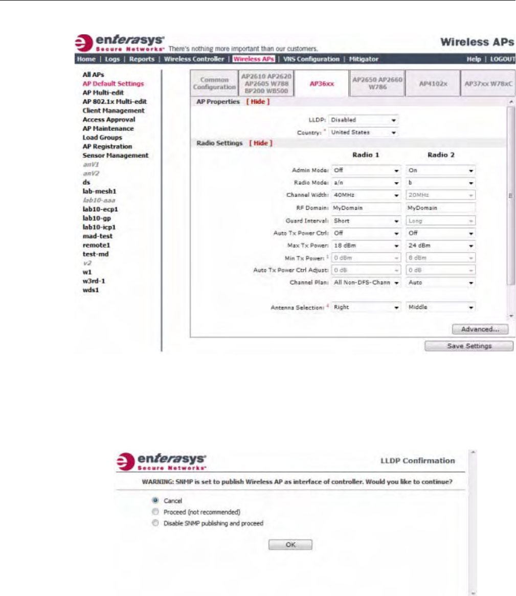
Configuring VLAN Tags for Wireless APs
3-84 Configuring the Wireless AP
3. ClicktheAP36xxtab.
4. IntheAPPropertiessection,dothefollowing:
–LLDP—ClicktoenableordisabletheWirelessAPfrombroadcastingLLDPinformation.
Thisoptionisdisabledbydefault.
IfSNMPisenabledontheEnterasysWirelessControllerandyouenableLLDP,theLLDP
Confirmationdialogisdisplayed.
–Selectoneofthefollowing:
‐Proceed(notrecommended)—SelectthisoptiontoenableLLDPandkeepSNMP
running,andthenclickOK.
‐DisableSNMPpublishing,andproceed—SelectthisoptiontoenableLLDPand
disableSNMP,andthenclickOK.
DRAFT

Configuring VLAN Tags for Wireless APs
User Guide, V8.01 3-85
FormoreinformationonenablingSNMP,seetheEnterasysWirelessConvergence
SoftwareMaintenanceGuide.
–AnnouncementInterval—IfLLDPisenabled,typehowoftentheWirelessAPadvertises
itsinformationbysendinganewLLDPpacket.Thisvalueismeasuredinseconds.
IftherearenochangestotheWirelessAPconfigurationthatimpacttheLLDP
information,theWirelessAPsendsanewLLDPpacketaccordingtothisschedule.
–AnnouncementDelay—IfLLDPisenabled,typetheannouncementdelay.Thisvalueis
measuredinseconds.IfachangetotheWirelessAPconfigurationoccurswhichimpacts
theLLDPinformation,theWirelessAPsendsanupdatedLLDPpacket.The
announcementdelayisthelengthoftimethatdelaysthenewpacketdelivery.The
announcementdelayhelpsminimizeLLDPpackettraffic.
–Country—Clickthecountryofoperation.Thisoptionisonlyavailablewithsome
licenses.
5. IntheRadioSettingssection,dothefollowingforeachradio:
–AdminMode—Forradios1and2,SelectOfftodisabletheradioorselectOntoenable
theradio:
–Radiomode—Clicktheradiomodeyouwanttoenable:
‐Radio1—a,a/n,orn‐strict.
‐Radio2—b,b/g,g,g/n,b/g/n,orn‐strict.
–ChannelWidth—Clickthechannelwidthfortheradio:
‐20MHz—Clicktoallow802.11nclientstousetheprimarychannel(20MHz)andnon‐
802.11nclients,beacons,andmulticaststousethe802.11b/gradioprotocols.
‐40MHz—Clicktoallow802.11nclientsthatsupportthe40MHzfrequencytouse
40MHz,20MHz,orthe802.11b/gradioprotocols.802.11nclientsthatdonotsupport
the40MHzfrequencycanuse20MHzorthe802.11b/gradioprotocolsandnon‐
802.11nclients,beacons,andmulticastsusethe802.11b/gradioprotocols.
‐Auto—Clicktoautomaticallyswitchbetween20MHzand40MHzchannelwidths,
dependingonhowbusytheextensionchannelis.
–RFDomain—TypeastringthatuniquelyidentifiesagroupofAPsthatcooperatein
managingRFchannelsandtransmissionpowerlevels.Themaximumlengthofthestring
is16characters.TheRFDomainisusedtoidentifyagroupofWirelessAPs.
–GuardInterval—Clickaguardinterval,LongorShort,whena40MHzchannelisused.
Enterasysrecommendsthatyouuseashortguardintervalinsmallrooms(forexample,a
smallofficespace)andalongguardintervalinlargerooms(forexample,aconference
hall).
–AutoTxPowerCtrl—ClicktoenableordisableATPCfromtheAutoTxPowerCtrl
drop‐downlist.ATPCautomaticallyadaptstransmissionpowersignalsaccordingtothe
coverageprovidedbytheWirelessAPs.Afteraperiodoftime,thesystemwillstabilize
itselfbasedontheRFcoverageofyourWirelessAPs.
Note: The Time to Live value cannot be directly edited. The Time to Live value is calculated as
four times the Announcement Interval value.
Note: Depending on the radio modes you select, some of the radio settings may not be available for
configuration.
DRAFT

Configuring VLAN Tags for Wireless APs
3-86 Configuring the Wireless AP
–MaxTxPower—ClicktheappropriateTxpowerlevelfromtheMaxTXPowerdrop‐
downlist.ThevaluesintheMaxTXPowerdrop‐downareindBm.
–MinTxPower—IfATPCisenabled,clicktheminimumTxpowerleveltowhichthe
rangeoftransmitpowercanbeadjusted:0to23(b/gorb/g/n)or24(aora/n)dBm.
Enterasysrecommendsthatyouselect0dBmtousetheentirerangeofpotentialTx
power.
–AutoTxPowerCtrlAdjust—IfATPCisenabled,clicktheTxpowerlevelthatcanbe
usedtoadjusttheATPCpowerlevelsthatthesystemhasassigned.Enterasys
recommendsthatyouuse0dBmduringyourinitialconfiguration.IfyouhaveanRFplan
thatrecommendsTxpowerlevelsforeachWirelessAP,comparetheactualTxpower
levelsyoursystemhasassignedagainsttherecommendedvaluesyourRFplanhas
provided.UsetheAutoTxPowerCtrlAdjustvaluetoachievetherecommendedvalues.
–ChannelPlan—IfACSisenabled,youcandefineachannelplanfortheWirelessAP.
Definingachannelplanallowsyoutolimitwhichchannelsareavailableforuseduringan
ACSscan.Forexample,youmaywanttoavoidusingspecificchannelsbecauseoflow
power,regulatorydomain,orradarinterference.
ForRadio1,clickoneofthefollowing:
‐Allchannels—ACSscansallchannelsforanoperatingchannelandreturnsboth
DFSandnon‐DFSchannels,ifavailable.
‐AllNon‐DFSChannels—ACSscansallnon‐DFSchannelsforanoperatingchannel.
ThisselectionisavailablewhenthereisatleastoneDFSchannelsupportedforthe
selectedcountry.
‐Custom—ToconfigureindividualchannelsfromwhichtheACSwillselectan
operatingchannel,clickConfigure.TheCustomChannelPlandialogdisplays.By
default,allchannelsparticipateinthechannelplan.Clicktheindividualchannelsyou
wanttoincludeinthechannelplan.Toselectcontiguouschannels,usetheShiftkey.
Toselectmultiple,non‐contiguouschannelsinthelist,usetheCTRLkey.ClickOKto
savetheconfiguration.
ForRadio2,clickoneofthefollowing:
‐3ChannelPlan—ACSwillscanthefollowingchannels:1,6,and11inNorth
America,and1,7,and13intherestoftheworld.
‐4ChannelPlan—ACSwillscanthefollowingchannels:1,4,7,and11inNorth
America,and1,5,9,and13intherestoftheworld.
‐Auto—ACSwillscanthedefaultchannelplanchannels:1,6,and11inNorth
America,and1,5,9,and13intherestoftheworld.
‐Custom—IfyouwanttoconfigureindividualchannelsfromwhichtheACSwill
selectanoperatingchannel,clickConfigure.TheAddChannelsdialogisdisplayed.
Clicktheindividualchannelsyouwanttoaddtothechannelplanwhilepressingthe
CTRLkey,andthenclickOK.
–AntennaSelection—Clicktheantenna,orantennacombination,youwanttoconfigure
onthisradio.
WhenyouconfiguretheWireless802.11nAPtousespecificantennas,thetransmission
powerisrecalculated;theCurrentTxPowerLevelvaluefortheradioisautomatically
adjustedtoreflecttherecentantennaconfiguration.Ittakesapproximately30secondsfor
thechangetotheCurrentTxPowerLevelvaluetobereflectedintheEnterasysWireless
Assistant.Also,theradioisresetcausingclientconnectionsonthisradiotobelost.
DRAFT

Configuring VLAN Tags for Wireless APs
User Guide, V8.01 3-87
6. Tomodifydefaultaccesspointadvancedsettings,clickAdvanced.TheAdvanceddialogis
displayed.
7. IntheAdvanceddialogAPPropertiessection,dothefollowing:
–PollTimeout—Typethetimeoutvalue,inseconds.TheWirelessAPusesthisvalueto
triggerre‐establishingthelinkwiththeEnterasysWirelessControllerifit(WirelessAP)
doesnotgetananswertoitspolling.Thedefaultvalueis10seconds.
–RemoteAccess—ClicktoEnableorDisabletelnetorSSHaccesstotheWirelessAP.
–Location‐basedservice—ClicktoEnableorDisablelocation‐basedserviceonthis
WirelessAP.Location‐basedserviceallowsyoutousethisWirelessAPwithanAeroScout
solution.
–Maintainclientsessionineventofpollfailure—Selectthisoption(ifusingabridgedat
APVNS)iftheAPshouldremainactiveifalinklosswiththecontrolleroccurs.This
optionisenabledbydefault.
–Restartserviceintheabsenceofcontroller—Selectthisoption(ifusingabridgedatAP
VNS)toensuretheWirelessAP’sradioscontinueprovidingserviceiftheWirelessAP’s
connectiontotheEnterasysWirelessControllerislost.Ifthisoptionisenabled,itallows
theWirelessAPtostartabridgedatAPVNSevenintheabsenceofaEnterasysWireless
Controller.
–Usebroadcastfordisassociation—SelectifyouwanttheWirelessAPtousebroadcast
disassociationwhendisconnectingallclients,insteadofdisassociatingeachclientoneby
one.ThiswillaffectthebehavioroftheAPunderthefollowingconditions:
‐IftheWirelessAPispreparingtorebootortoenteroneofthespecialmodes(DRM
initialchannelselection).
‐IfaBSSIDisdeactivatedorremovedontheWirelessAP.
Thisoptionisdisabledbydefault.
8. IntheAdvanceddialogRadioSettingssection,dothefollowing:
–DTIM—TypethedesiredDTIM(DeliveryTrafficIndicationMessage)period—the
numberofbeaconintervalsbetweentwoDTIMbeacons.Toensurethebestclientpower
savings,usealargenumber.Forexample,5.Useasmallnumbertominimizebroadcast
andmulticastdelay.Thedefaultvalueis5.
–BeaconPeriod—Typethedesiredtime,inmilliseconds,betweenbeacontransmissions.
Thedefaultvalueis100milliseconds.
–RTS/CTS—Typethepacketsizethreshold,inbytes,abovewhichthepacketwillbe
precededbyanRTS/CTS(RequesttoSend/CleartoSend)handshake.Thedefaultvalueis
2346,whichmeansallpacketsaresentwithoutRTS/CTS.Reducethisvalueonlyif
necessary.
–Frag.Threshold—Foreachradio,typethefragmentsizethreshold,inbytes,above
whichthepacketswillbefragmentedbytheAPpriortotransmission.Thedefaultvalueis
2346,whichmeansallpacketsaresentunfragmented.Reducethisvalueonlyifnecessary.
Note: Antenna Selection is not applicable to the AP3605.
Note: If you are configuring session availability, the Poll Timeout value should be 1.5 to 2 times of
Detect link failure value on AP Properties screen. For more information, see “Session Availability”
on page 11-9.
DRAFT

Configuring VLAN Tags for Wireless APs
3-88 Configuring the Wireless AP
–Max%ofnon‐unicasttrafficperBeaconperiod—Enterthemaximumpercentageof
timethattheAPwilltransmitnon‐unicastpackets(broadcastandmulticasttraffic)for
eachconfiguredBeaconPeriod.Foreachnon‐unicastpackettransmitted,thesystem
calculatestheairtimeusedbyeachpacketanddropsallpacketsthatexceedthe
configuredmaximumpercentage.Byrestrictingnon‐unicasttraffic,youlimittheimpact
ofbroadcastsandmulticastsonoverallsystemperformance.
–MaximumDistance—Enteravaluefrom100to15,000metersthatidentifiesthe
maximumlinkdistancebetweenAPsthatparticipateinaWDS.Thisvalueensuresthat
theacknowledgementofcommunicationbetweenAPsdoesnotexceedthetimeoutvalue
predefinedbythe802.11standard.Thedefaultvalueis100meters.Ifthelinkdistance
betweenAPsisgreaterthan100meters,configurethemaximumdistanceupto15,000
meterssothatthesoftwareincreasesthetimeoutvalueproportionallywiththedistance
betweenAPs.
Donotchangethedefaultsettingfortheradiothatprovidesserviceto802.11clientsonly.
–DynamicChannelSelection—ToenableDynamicChannelSelection,clickoneofthe
following:
‐MonitorMode—IftrafficornoiselevelsexceedtheconfiguredDCSthresholds,an
alarmistriggeredandaninformationlogisgenerated.
‐ActiveMode—IftrafficornoiselevelsexceedtheconfiguredDCSthresholds,an
alarmistriggeredandaninformationlogisgenerated.Inaddition,theWirelessAP
willceaseoperatingonthecurrentchannelandACSisemployedtoautomatically
selectanalternatechannelfortheWirelessAPtooperateon.
–DCSNoiseThreshold—Typethenoiseinterferencelevel,measuredindBm,afterwhich
ACSwillscanforanewoperatingchannelfortheWirelessAPifthethresholdis
exceeded.
–DCSChannelOccupancyThreshold—Typethechannelutilizationlevel,measuredasa
percentage,afterwhichACSwillscanforanewoperatingchannelfortheWirelessAPif
thethresholdisexceeded.
–DCSUpdatePeriod—Typethetime,measuredinminutesthatdeterminestheperiod
duringwhichtheWirelessAPaveragestheDCSNoiseThresholdandDCSChannel
OccupancyThresholdmeasurements.Ifeitheroneofthesethresholdsisexceeded,then
theWirelessAPwilltriggerACS.
–Preamble—Clickapreambletypefor11b‐specific(CCK)rates:Short,Long,orAuto.The
recommendedvalueisAuto.ClickShortifyouaresurethatthereisnopre‐11bAPora
clientinthevicinityofthisAP.ClickLongifcompatibilitywithpre‐11bclientsisrequired.
–ProtectionMode—Clickaprotectionmode:None,Auto,orAlways.Thedefaultand
recommendedsettingisAuto.ClickNoneif11bAPsandclientsarenotexpected.Click
Alwaysifyouexpectmany11b‐onlyclients.
–ProtectionRate—Clickaprotectionrate:1,2,5.5,or11Mbps.Thedefaultand
recommendedsettingis11.Onlyreducetherateiftherearemany11bclientsinthe
environmentorifthedeploymenthasareaswithpoorcoverage.Forexample,rateslower
than11Mbpsarerequiredtoensurecoverage.
–ProtectionType—Clickaprotectiontype:CTSOnlyorRTSCTS.Thedefaultand
recommendedsettingisCTSOnly.ClickRTSCTSonlyifan11bAPthatoperatesonthe
samechannelisdetectedintheneighborhood,oriftherearemany11b‐onlyclientsinthe
environment.
DRAFT

Configuring VLAN Tags for Wireless APs
User Guide, V8.01 3-89
9. IntheAdvanceddialog11nSettingssection,dothefollowing:
–ProtectionMode—Clickaprotectionmode:None,Auto,orAlways.Thedefaultand
recommendedsettingisAuto.ClickNoneif11bAPsandclientsarenotexpected.Click
Alwaysifyouexpectmany11b‐onlyclients.
–ProtectionType—Clickaprotectiontype,CTSOnlyorRTS‐CTS,whena40MHz
channelisused.Thisprotectshighthroughputtransmissionsonextensionchannelsfrom
interferencefromnon‐11nAPsandclients.
–40MHzProt.ChannelOffset—Selecta20MHzchanneloffsetifthedeploymentisusing
channelsthatare20MHzapart(forexample,usingchannels1,5,9,and13)ora25MHz
channeloffsetifthedeploymentisusingchannelsthatare25MHzapart(forexample,
usingchannels1,6,and11).
–40MHzChannelBusyThreshold—Typetheextensionchannelthresholdpercentage,
whichifexceeded,willdisabletransmissionsontheextensionchannel(40MHz).
–AggregateMSDUs—ClickanaggregateMSDUmode:EnabledorDisabled.Aggregate
MSDUincreasesthemaximumframetransmissionsize.
–AggregateMPDUs—ClickanaggregateMPDUmode:EnabledorDisabled.Aggregate
MPDUprovidesasignificantimprovementinthroughput.
–AggregateMPDUMaxLength—TypethemaximumlengthoftheaggregateMPDU.The
valuerangeis1024‐65535bytes.
–Agg.MPDUMax#ofSub‐frames—Typethemaximumnumberofsub‐framesofthe
aggregateMPDU.Thevaluerangeis2‐64.
–ADDBASupport—ClickanADDBAsupportmode:EnabledorDisabled.ADDBA,or
blockacknowledgement,providesacknowledgementofagroupofframesinsteadofa
singleframe.ADDBASupportmustbeenabledifAggregateMPDUisenable.
10. ClickClose.TheAdvanceddialogisclosed.
11. Tosaveyourchanges,clickSaveSettings.
Configure AP2650/60, W786 Default AP Settings
To Configure AP2650/60, W786 Default Access Point Settings:
1. Fromthetopmenu,clickWirelessAPs.TheWirelessAPscreenisdisplayed.
2. Intheleftpane,clickAPDefaultSettings.TheCommonConfigurationtabisdisplayed.
DRAFT
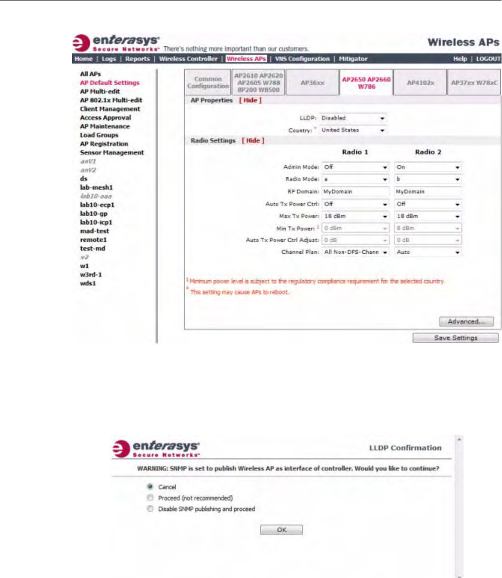
Configuring VLAN Tags for Wireless APs
3-90 Configuring the Wireless AP
3. ClicktheAP2650AP2660W786tab.
4. IntheAPPropertiessection,dothefollowing:
–LLDP—ClicktoEnableorDisabletheWirelessAPfrombroadcastingLLDP
information.Thisoptionisdisabledbydefault.
IfSNMPisenabledontheEnterasysWirelessControllerandyouenableLLDP,theLLDP
Confirmationdialogisdisplayed.
–Sele
ctoneofthefollowing:
‐Proceed(notrecommended)—SelectthisoptiontoenableLLDPandkeepSNMP
running,andthenclickOK.
‐DisableSNMPpublishing,andproceed—SelectthisoptiontoenableLLDPand
disableSNMP,andthenclickOK.
DRAFT

Configuring VLAN Tags for Wireless APs
User Guide, V8.01 3-91
FormoreinformationonenablingSNMP,seetheEnterasysWirelessConvergence
SoftwareMaintenanceGuide.
–AnnouncementInterval—IfLLDPisenabled,typehowoftentheWirelessAPadvertises
itsinformationbysendinganewLLDPpacket.Thisvalueismeasuredinseconds.
IftherearenochangestotheWirelessAPconfigurationthatimpacttheLLDP
information,theWirelessAPsendsanewLLDPpacketaccordingtothisschedule.
–AnnouncementDelay—IfLLDPisenabled,typetheannouncementdelay.Thisvalueis
measuredinseconds.IfachangetotheWirelessAPconfigurationoccurswhichimpacts
theLLDPinformation,theWirelessAPsendsanupdatedLLDPpacket.The
announcementdelayisthelengthoftimethatdelaysthenewpacketdelivery.The
announcementdelayhelpsminimizeLLDPpackettraffic.
5. Country—Clickthecountryofoperation.Thisoptionisonlyavailablewithsomelicenses.
6. IntheRadioSettingssection,dothefollowingforeachradio:
–AdminMode—ForRadios1and2,SelectOfftodisabletheradioorselectOntoenable
theradio:
–Radiomode—Clicktheradiomodeyouwanttoenable:
‐Radio1—b,g,b/g,ora.
‐Radio2—b,g,b/g,ora.
–RFDomain—TypeastringthatuniquelyidentifiesagroupofAPsthatcooperatein
managingRFchannelsandtransmissionpowerlevels.Themaximumlengthofthestring
is16characters.TheRFDomainisusedtoidentifyagroupofWirelessAPs.
–AutoTxPowerCtrl—ClicktoeitherenableordisableATPCfromtheAutoTxPower
Ctrldrop‐downlist.ATPCautomaticallyadaptstransmissionpowersignalsaccordingto
thecoverageprovidedbytheWirelessAPs.Afteraperiodoftime,thesystemwill
stabilizeitselfbasedontheRFcoverageofyourWirelessAPs.
–MaxTxPower—ClicktheappropriateTxpowerlevelfromtheMaxTXPowerdrop‐
downlist.ThevaluesintheMaxTXPowerdrop‐downareindBm.
–MinTxPower—IfATPCisenabled,clicktheminimumTxpowerleveltowhichthe
rangeoftransmitpowercanbeadjusted:0to23(b/gorb/g/n)or24(aora/n)dBm.
Enterasysrecommendsthatyouselect0dBmtousetheentirerangeofpotentialTx
power.
–AutoTxPowerCtrlAdjust—IfATPCisenabled,clicktheTxpowerlevelthatcanbe
usedtoadjusttheATPCpowerlevelsthatthesystemhasassigned.Enterasys
recommendsthatyouuse0dBmduringyourinitialconfiguration.IfyouhaveanRFplan
thatrecommendsTxpowerlevelsforeachWirelessAP,comparetheactualTxpower
levelsyoursystemhasassignedagainsttherecommendedvaluesyourRFplanhas
provided.UsetheAutoTxPowerCtrlAdjustvaluetoachievetherecommendedvalues.
–ChannelPlan—IfACSisenabledyoucandefineachannelplanfortheWirelessAP.
Definingachannelplanallowsyoutolimitwhichchannelsareavailableforuseduringan
Note: The Time to Live value cannot be directly edited. The Time to Live value is calculated as
four times the Announcement Interval value.
Note: Depending on the radio modes you select, some of the radio settings may not be available for
configuration.
DRAFT

Configuring VLAN Tags for Wireless APs
3-92 Configuring the Wireless AP
ACSscan.Forexample,youmaywanttoavoidusingspecificchannelsbecauseoflow
power,regulatorydomain,orradarinterference.
Ifyouhavesettheradioto802.11a,clickoneofthefollowing:
‐Allchannels—ACSscansallchannelsforanoperatingchannelandreturnsboth
DFSandnon‐DFSchannels,ifavailable.
‐AllNon‐DFSChannels—ACSscansallnon‐DFSchannelsforanoperatingchannel.
ThisselectionisavailablewhenthereisatleastoneDFSchannelsupportedforthe
selectedcountry.
‐Custom—ToconfigureindividualchannelsfromwhichtheACSwillselectan
operatingchannel,clickConfigure.TheCustomChannelPlandialogdisplays.By
default,allchannelsparticipateinthechannelplan.Clicktheindividualchannelsyou
wanttoincludeinthechannelplan.Toselectcontiguouschannels,usetheShiftkey.
Toselectmultiple,non‐contiguouschannelsinthelist,usetheCTRLkey.ClickOKto
savetheconfiguration.
Ifyouhavesettheradioto802.11b,g,orb/g,clickoneofthefollowing:
‐3ChannelPlan—ACSwillscanthefollowingchannels:1,6,and11inNorth
America,and1,7,and13intherestoftheworld.
‐4ChannelPlan—ACSwillscanthefollowingchannels:1,4,7,and11inNorth
America,and1,5,9,and13intherestoftheworld.
‐Auto—ACSwillscanthedefaultchannelplanchannels:1,6,and11inNorth
America,and1,5,9,and13intherestoftheworld.
‐Custom—IfyouwanttoconfigureindividualchannelsfromwhichtheACSwill
selectanoperatingchannel,clickConfigure.TheAddChannelsdialogisdisplayed.
Clicktheindividualchannelsyouwanttoaddtothechannelplanwhilepressingthe
CTRLkey,andthenclickOK.
7. Tomodifydefaultaccesspointadvancedsettings,clickAdvanced.TheAdvanceddialogis
displayed.
8. IntheAdvanceddialogAPPropertiessection,dothefollowing:
–PollTimeout—Typethetimeoutvalue,inseconds.TheWirelessAPusesthisvalueto
triggerre‐establishingthelinkwiththeEnterasysWirelessControllerifit(WirelessAP)
doesnotgetananswertoitspolling.Thedefaultvalueis10seconds.
–RemoteAccess—ClicktoEnableorDisabletelnetorSSHaccesstotheWirelessAP.
–Location‐basedservice—ClicktoEnableorDisablelocation‐basedserviceonthis
WirelessAP.Location‐basedserviceallowsyoutousethisWirelessAPwithanAeroScout
solution.
–Maintainclientsessionineventofpollfailure—Selectthisoption(ifusingabridgedat
APVNS)iftheAPshouldremainactiveifalinklosswiththecontrolleroccurs.This
optionisenabledbydefault.
–Restartserviceintheabsenceofcontroller—Selectthisoption(ifusingabridgedatAP
VNS)toensuretheWirelessAP’sradioscontinueprovidingserviceiftheWirelessAP’s
connectiontotheEnterasysWirelessControllerislost.Ifthisoptionisenabled,itallows
theWirelessAPtostartabridgedatAPVNSevenintheabsenceofaEnterasysWireless
Controller.
Note: If you are configuring session availability, the Poll Timeout value should be 1.5 to 2 times of
Detect link failure value on AP Properties screen. For more information, see “Session Availability”
on page 11-9.
DRAFT

Configuring VLAN Tags for Wireless APs
User Guide, V8.01 3-93
–Usebroadcastfordisassociation—SelectifyouwanttheWirelessAPtousebroadcast
disassociationwhendisconnectingallclients,insteadofdisassociatingeachclientoneby
one.ThiswillaffectthebehavioroftheAPunderthefollowingconditions:
‐IftheWirelessAPispreparingtorebootortoenteroneofthespecialmodes(DRM
initialchannelselection).
‐IfaBSSIDisdeactivatedorremovedontheWirelessAP.
Thisoptionisdisabledbydefault.
9. IntheAdvanceddialogRadioSettingssection,dothefollowing:
–DTIM—TypethedesiredDTIM(DeliveryTrafficIndicationMessage)period—the
numberofbeaconintervalsbetweentwoDTIMbeacons.Toensurethebestclientpower
savings,usealargenumber.Forexample,5.Useasmallnumbertominimizebroadcast
andmulticastdelay.Thedefaultvalueis5.
–BeaconPeriod—Typethedesiredtime,inmilliseconds,betweenbeacontransmissions.
Thedefaultvalueis100milliseconds.
–RTS/CTS—Typethepacketsizethreshold,inbytes,abovewhichthepacketwillbe
precededbyanRTS/CTS(RequesttoSend/CleartoSend)handshake.Thedefaultvalueis
2346,whichmeansallpacketsaresentwithoutRTS/CTS.Reducethisvalueonlyif
necessary.
–Frag.Threshold—Typethefragmentsizethreshold,inbytes,abovewhichthepackets
willbefragmentedbytheAPpriortotransmission.Thedefaultvalueis2346,which
meansallpacketsaresentunfragmented.Reducethisvalueonlyifnecessary.
–Max%ofnon‐unicasttrafficperBeaconperiod—Enterthemaximumpercentageof
timethattheAPwilltransmitnon‐unicastpackets(broadcastandmulticasttraffic)for
eachconfiguredBeaconPeriod.Foreachnon‐unicastpackettransmitted,thesystem
calculatestheairtimeusedbyeachpacketanddropsallpacketsthatexceedthe
configuredmaximumpercentage.Byrestrictingnon‐unicasttraffic,youlimittheimpact
ofbroadcastsandmulticastsonoverallsystemperformance.
–MaximumDistance—Enteravaluefrom100to15,000metersthatidentifiesthe
maximumlinkdistancebetweenAPsthatparticipateinaWDS.Thisvalueensuresthat
theacknowledgementofcommunicationbetweenAPsdoesnotexceedthetimeoutvalue
predefinedbythe802.11standard.Thedefaultvalueis100meters.Ifthelinkdistance
betweenAPsisgreaterthan100meters,configurethemaximumdistanceupto15,000
meterssothatthesoftwareincreasesthetimeoutvalueproportionallywiththedistance
betweenAPs.
Donotchangethedefaultsettingfortheradiothatprovidesserviceto802.11clientsonly.
–DynamicChannelSelection—Clickoneofthefollowing:
‐Off—DisablesDCS.
‐MonitorMode—IftrafficornoiselevelsexceedtheconfiguredDCSthresholds,an
alarmistriggeredandaninformationlogisgenerated.
‐ActiveMode—IftrafficornoiselevelsexceedtheconfiguredDCSthresholds,an
alarmistriggeredandaninformationlogisgenerated.Inaddition,theWirelessAP
willceaseoperatingonthecurrentchannelandACSisemployedtoautomatically
selectanalternatechannelfortheWirelessAPtooperateon.
‐DCSNoiseThreshold—IfDCSisenabled,typethenoiseinterferencelevel,
measuredindBm,afterwhichACSwillscanforanewoperatingchannelforthe
WirelessAPifthethresholdisexceeded.
DRAFT

Configuring VLAN Tags for Wireless APs
3-94 Configuring the Wireless AP
‐DCSChannelOccupancyThreshold—IfDCSisenabled,typethechannel
utilizationlevel,measuredasapercentage,afterwhichACSwillscanforanew
operatingchannelfortheWirelessAPifthethresholdisexceeded.
‐DCSUpdatePeriod—IfDCSisenabled,typethetime,measuredinminutesthat
determinestheperiodduringwhichtheWirelessAPaveragestheDCSNoise
ThresholdandDCSChannelOccupancyThresholdmeasurements.Ifeitheroneof
thesethresholdsisexceeded,thentheWirelessAPwilltriggerACS.
–RxDiversity—ClickBestforthebestsignalfrombothantennas,orLeftorRightto
chooseeitherofthetwodiversityreceivingantennas.Thedefaultandrecommended
selectionisBest.Ifonlyoneantennaisconnected,usethecorrespondingLeftorRight
diversitysetting.DonotuseBestiftwoidenticalantennasarenotused.
–TxDiversity—ClickAlternateforthebestsignalfrombothantennas,orLeftorRightto
chooseeitherofthetwodiversityreceivingantennas.ThedefaultselectionisAlternate
thatmaximizesperformanceformostclients.However,someclientsmaybehaveoddly
withTxDiversitysettoAlternate.Underthosecircumstances,Enterasysrecommends
thatyouuseeitherLeftorRightforTxDiversity.Ifonlyoneantennaisconnected,usethe
correspondingLeftorRightdiversitysetting.DonotuseAlternateiftwoidentical
antennasarenotused.
–Preamble—Clickapreambletypefor11b‐specific(CCK)rates:Short,Long,orAuto.The
recommendedvalueisAuto.ClickShortifyouaresurethatthereisnopre‐11bAPora
clientinthevicinityofthisAP.ClickLongifcompatibilitywithpre‐11bclientsisrequired.
–ProtectionMode—Clickaprotectionmode:None,Auto,orAlways.Thedefaultand
recommendedsettingisAuto.ClickNoneif11bAPsandclientsarenotexpected.Click
Alwaysifyouexpectmany11b‐onlyclients.
–ProtectionRate—Clickaprotectionrate:1,2,5.5,or11Mbps.Thedefaultand
recommendedsettingis11.Onlyreducetherateiftherearemany11bclientsinthe
environmentorifthedeploymenthasareaswithpoorcoverage.Forexample,rateslower
than11Mbpsarerequiredtoensurecoverage.
–ProtectionType—Clickaprotectiontype:CTSOnlyorRTSCTS.Thedefaultand
recommendedsettingisCTSOnly.ClickRTSCTSonlyifan11bAPthatoperatesonthe
samechannelisdetectedintheneighborhood,oriftherearemany11b‐onlyclientsinthe
environment.
10. IntheAdvanceddialogEnhancedRateControlsection,dothefollowing:
–MinBasicRate—Foreachradio,clicktheminimumdataratethatmustbesupportedby
allstationsinaBSS:
‐Click1,2,5.5,6or11Mbpsfor11b‐onlymode.
‐Click1,2,5.5,6,11,12,or24Mbpsfor11b+11gmode.
‐Click6,12,or24Mbpsfor11aand11gmodes.
Ifnecessary,theMaxBasicRatechoicesadjustautomaticallytobehigherorequaltothe
MinBasicRate.IfbothMinBasicRateandMaxBasicRatearesettoan11g‐specific
(OFDM)rate,(forexample,6,12,or24Mbps)allbasicrateswillbe11g‐specific.
–MaxBasicRate—Foreachradio,clickthemaximumdataratethatmustbesupportedby
allstationsinaBSS:
‐Click1,2,5.5,or11Mbpsfor11b‐onlymode.
‐Click1,2,5.5,6,11,12,or24Mbpsfor11b+11gmode.
‐Click6,12,or24Mbpsfor11aand11gmodes.
DRAFT

Configuring VLAN Tags for Wireless APs
User Guide, V8.01 3-95
Ifnecessary,theMaxBasicRatechoicesadjustautomaticallytobehigherorequaltothe
MinBasicRate.IfbothMinBasicRateandMaxBasicRatearesettoan11g‐specific
(OFDM)rate,(forexample,6,12,or24Mbps)allbasicrateswillbe11g‐specific.
–MaxOperationalRate—Foreachradio,clickthemaximumdataratethatclientscan
operateatwhileassociatedwiththeAP:
‐Click1,2,5.5,or11Mbpsfor11b‐onlymode.
‐Click1,2,5.5,6,9,11,12,18,24,36,28,or54Mbpsfor11b+11gmodes.
‐Click6,9,12,18,24,36,48,or54Mbpsfor11aand11gmodes.
Ifnecessary,theMaxOperationalRatechoicesadjustautomaticallytobehigherorequal
totheMinBasicRate.
11. IntheAdvanceddialogNoofRetriessection,dothefollowing:
–BackgroundBK—Foreachradio,clickthenumberofretriesfortheBackground
transmissionqueue.Thedefaultvalueisadaptive(multi‐rate).Therecommendedsetting
isadaptive(multi‐rate).
–BestEffortBE—Foreachradio,clickthenumberofretriesfortheBestEffort
transmissionqueue.Thedefaultvalueisadaptive(multi‐rate).Therecommendedsetting
isadaptive(multi‐rate).
–VideoVI—Foreachradio,clickthenumberofretriesfortheVideotransmissionqueue.
Thedefaultvalueisadaptive(multi‐rate).Therecommendedsettingisadaptive(multi‐
rate).
–VoiceVO—Foreachradio,clickthenumberofretriesfortheVoicetransmissionqueue.
Thedefaultvalueisadaptive(multi‐rate).Therecommendedsettingisadaptive(multi‐
rate).
–TurboVoic eTVO—Foreachradio,clickthenumberofretriesfortheTurboVoice
transmissionqueue.Thedefaultvalueisadaptive(multi‐rate).Therecommendedsetting
isadaptive(multi‐rate).
12. ClickClose.TheAdvanceddialogisclosed.
13. Tosaveyourchanges,clickSaveSettings.
Configure AP4102x Default AP Settings
To Configure AP4102x Default AP Settings:
1. Fromthetopmenu,clickWirelessAPs.TheWirelessAPscreenisdisplayed.
2. Intheleftpane,clickAPDefaultSettings.TheCommonConfigurationtabisdisplayed.
DRAFT
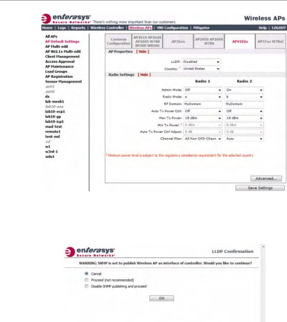
Configuring VLAN Tags for Wireless APs
3-96 Configuring the Wireless AP
3. ClicktheAP4102xtab.
4. IntheAPPropertiessection,dothefollowing:
–LLDP—ClicktoEnableorDisabletheWirelessAPfrombroadcastingLLDP
information.Thisoptionisdisabledbydefault.
IfSNMPisenabledontheEnterasysWirelessControllerandyouenableLLDP,theLLDP
Confirmationdialogisdisplayed.
–Selectoneofthefollowing:
‐Proceed(notrecommended)—SelectthisoptiontoenableLLDPandkeepSNMP
running,andthenclickOK.
‐DisableSNMPpublishing,andproceed—SelectthisoptiontoenableLLDPand
disableSNMP,andthenclickOK.
FormoreinformationonenablingSNMP,seetheEnterasysWirelessConvergence
SoftwareMaintenanceGuide.
DRAFT

Configuring VLAN Tags for Wireless APs
User Guide, V8.01 3-97
–AnnouncementInterval—IfLLDPisenabled,typehowoftentheWirelessAPadvertises
itsinformationbysendinganewLLDPpacket.Thisvalueismeasuredinseconds.
IftherearenochangestotheWirelessAPconfigurationthatimpacttheLLDP
information,theWirelessAPsendsanewLLDPpacketaccordingtothisschedule.
–AnnouncementDelay—IfLLDPisenabled,typetheannouncementdelay.Thisvalueis
measuredinseconds.IfachangetotheWirelessAPconfigurationoccurswhichimpacts
theLLDPinformation,theWirelessAPsendsanupdatedLLDPpacket.The
announcementdelayisthelengthoftimethatdelaysthenewpacketdelivery.The
announcementdelayhelpsminimizeLLDPpackettraffic.
–Country—Clickthecountryofoperation.Thisoptionisonlyavailablewithsome
licenses.
5. IntheRadioSettingssection,dothefollowingforeachradio:
–AdminMode—Forradios1and2,SelectOfftodisabletheradioorselectOntoenable
theradio:
–Radiomode—Clicktheradiomodeyouwanttoenable:
‐Radio1—a.
‐Radio2—b,g,orb/g.
–RFDomain—TypeastringthatuniquelyidentifiesagroupofAPsthatcooperatein
managingRFchannelsandtransmissionpowerlevels.Themaximumlengthofthestring
is16characters.TheRFDomainisusedtoidentifyagroupofWirelessAPs.
–AutoTxPowerCtrl—ClicktoeitherenableordisableATPCfromtheAutoTxPower
Ctrldrop‐downlist.ATPCautomaticallyadaptstransmissionpowersignalsaccordingto
thecoverageprovidedbytheWirelessAPs.Afteraperiodoftime,thesystemwill
stabilizeitselfbasedontheRFcoverageofyourWirelessAPs.
–MaxTxPower—ClicktheappropriateTxpowerlevelfromtheMaxTXPowerdrop‐
downlist.ThevaluesintheMaxTXPowerdrop‐downareindBm.
–MinTxPower—IfATPCisenabled,clicktheminimumTxpowerleveltowhichthe
rangeoftransmitpowercanbeadjusted:0to23(a)or24(b,g,orb/g)dBm.Enterasys
recommendsthatyouselect0dBmtousetheentirerangeofpotentialTxpower.
–AutoTxPowerCtrlAdjust—IfATPCisenabled,clicktheTxpowerlevelthatcanbe
usedtoadjusttheATPCpowerlevelsthatthesystemhasassigned.Enterasys
recommendsthatyouuse0dBmduringyourinitialconfiguration.IfyouhaveanRFplan
thatrecommendsTxpowerlevelsforeachWirelessAP,comparetheactualTxpower
levelsyoursystemhasassignedagainsttherecommendedvaluesyourRFplanhas
provided.UsetheAutoTxPowerCtrlAdjustvaluetoachievetherecommendedvalues.
–ChannelPlan—IfACSisenabledyoucandefineachannelplanfortheWirelessAP.
Definingachannelplanallowsyoutolimitwhichchannelsareavailableforuseduringan
ACSscan.Forexample,youmaywanttoavoidusingspecificchannelsbecauseoflow
power,regulatorydomain,orradarinterference.
Note: The Time to Live value cannot be directly edited. The Time to Live value is calculated as
four times the Announcement Interval value.
Note: Depending on the radio modes you select, some of the radio settings may not be available for
configuration.
DRAFT

Configuring VLAN Tags for Wireless APs
3-98 Configuring the Wireless AP
ForRadio1,clickoneofthefollowing:
‐Allchannels—ACSscansallchannelsforanoperatingchannelandreturnsboth
DFSandnon‐DFSchannels,ifavailable.
‐AllNon‐DFSChannels—ACSscansallnon‐DFSchannelsforanoperatingchannel.
ThisselectionisavailablewhenthereisatleastoneDFSchannelsupportedforthe
selectedcountry.
‐Custom—ToconfigureindividualchannelsfromwhichtheACSwillselectan
operatingchannel,clickConfigure.TheCustomChannelPlandialogdisplays.By
default,allchannelsparticipateinthechannelplan.Clicktheindividualchannelsyou
wanttoincludeinthechannelplan.Toselectcontiguouschannels,usetheShiftkey.
Toselectmultiple,non‐contiguouschannelsinthelist,usetheCTRLkey.ClickOKto
savetheconfiguration.
ForRadio2,clickoneofthefollowing:
‐3ChannelPlan—ACSwillscanthefollowingchannels:1,6,and11inNorth
America,and1,7,and13intherestoftheworld.
‐4ChannelPlan—ACSwillscanthefollowingchannels:1,4,7,and11inNorth
America,and1,5,9,and13intherestoftheworld.
‐Auto—ACSwillscanthedefaultchannelplanchannels:1,6,and11inNorth
America,and1,5,9,and13intherestoftheworld.
‐‘Custom—IfyouwanttoconfigureindividualchannelsfromwhichtheACSwill
selectanoperatingchannel,clickConfigure.TheAddChannelsdialogisdisplayed.
Clicktheindividualchannelsyouwanttoaddtothechannelplanwhilepressingthe
CTRLkey,andthenclickOK.
6. Tomodifydefaultaccesspointadvancedsettings,clickAdvanced.TheAdvanceddialogis
displayed.
7. IntheAdvanceddialogAPPropertiessection,dothefollowing:
–PollTimeout—Typethetimeoutvalue,inseconds.TheWirelessAPusesthisvalueto
triggerre‐establishingthelinkwiththeEnterasysWirelessControllerifit(WirelessAP)
doesnotgetananswertoitspolling.Thedefaultvalueis10seconds.
–RemoteAccess—ClicktoEnableorDisabletelnetorSSHaccesstotheWirelessAP.
–Location‐basedservice—ClicktoEnableorDisablelocation‐basedserviceonthis
WirelessAP.Location‐basedserviceallowsyoutousethisWirelessAPwithanAeroScout
solution.
–Maintainclientsessionineventofpollfailure—ClicktoEnableorDisable(ifusinga
bridgedatAPVNS)iftheAPshouldremainactiveifalinklosswiththecontroller
occurs.Thisoptionisenabledbydefault.
–Restartserviceintheabsenceofcontroller—ClicktoEnableorDisable(ifusinga
bridgedatAPVNS)toensuretheWirelessAPs’radioscontinueprovidingserviceifthe
WirelessAP’sconnectiontotheEnterasysWirelessControllerislost.Ifthisoptionis
enabled,itallowstheWirelessAPtostartabridgedatAPVNSevenintheabsenceofa
EnterasysWirelessController.
–Usebroadcastfordisassociation—ClicktoEnableorDisableifyouwanttheWireless
APtousebroadcastdisassociationwhendisconnectingallclients,insteadof
Note: If you are configuring session availability, the Poll Timeout value should be 1.5 to 2 times of
Detect link failure value on AP Properties screen. For more information, see “Session Availability”
on page 11-9.
DRAFT

Configuring VLAN Tags for Wireless APs
User Guide, V8.01 3-99
disassociatingeachclientonebyone.ThiswillaffectthebehavioroftheAPunderthe
followingconditions:
‐IftheWirelessAPispreparingtorebootortoenteroneofthespecialmodes(DRM
initialchannelselection).
‐IfaBSSIDisdeactivatedorremovedontheWirelessAP.
Thisoptionisdisabledbydefault.
8. IntheAdvanceddialogRadioSettingssection,dothefollowing:
–DTIM—TypethedesiredDTIM(DeliveryTrafficIndicationMessage)period—the
numberofbeaconintervalsbetweentwoDTIMbeacons.Toensurethebestclientpower
savings,usealargenumber.Forexample,5.Useasmallnumbertominimizebroadcast
andmulticastdelay.Thedefaultvalueis5.
–BeaconPeriod—Typethedesiredtime,inmilliseconds,betweenbeacontransmissions.
Thedefaultvalueis100milliseconds.
–RTS/CTS—Typethepacketsizethreshold,inbytes,abovewhichthepacketwillbe
precededbyanRTS/CTS(RequesttoSend/CleartoSend)handshake.Thedefaultvalueis
2346,whichmeansallpacketsaresentwithoutRTS/CTS.Reducethisvalueonlyif
necessary.
–Frag.Threshold—Typethefragmentsizethreshold,inbytes,abovewhichthepackets
willbefragmentedbytheAPpriortotransmission.Thedefaultvalueis2346,which
meansallpacketsaresentunfragmented.Reducethisvalueonlyifnecessary.
–Max%ofnon‐unicasttrafficperBeaconperiod—Enterthemaximumpercentageof
timethattheAPwilltransmitnon‐unicastpackets(broadcastandmulticasttraffic)for
eachconfiguredBeaconPeriod.Foreachnon‐unicastpackettransmitted,thesystem
calculatestheairtimeusedbyeachpacketanddropsallpacketsthatexceedthe
configuredmaximumpercentage.Byrestrictingnon‐unicasttraffic,youlimittheimpact
ofbroadcastsandmulticastsonoverallsystemperformance.
–MaximumDistance—Enteravaluefrom100to15,000metersthatidentifiesthe
maximumlinkdistancebetweenAPsthatparticipateinaWDS.Thisvalueensuresthat
theacknowledgementofcommunicationbetweenAPsdoesnotexceedthetimeoutvalue
predefinedbythe802.11standard.Thedefaultvalueis100meters.Ifthelinkdistance
betweenAPsisgreaterthan100meters,configurethemaximumdistanceupto15,000
meterssothatthesoftwareincreasesthetimeoutvalueproportionallywiththedistance
betweenAPs.
Donotchangethedefaultsettingfortheradiothatprovidesserviceto802.11clientsonly.
–DynamicChannelSelection—Clickoneofthefollowing:
‐Off—DisablesDCS.
‐MonitorMode—IftrafficornoiselevelsexceedtheconfiguredDCSthresholds,an
alarmistriggeredandaninformationlogisgenerated.
‐ActiveMode—IftrafficornoiselevelsexceedtheconfiguredDCSthresholds,an
alarmistriggeredandaninformationlogisgenerated.Inaddition,theWirelessAP
willceaseoperatingonthecurrentchannelandACSisemployedtoautomatically
selectanalternatechannelfortheWirelessAPtooperateon.
‐DCSNoiseThreshold—IfDCSisenabled,typethenoiseinterferencelevel,
measuredindBm,afterwhichACSwillscanforanewoperatingchannelforthe
WirelessAPifthethresholdisexceeded.
DRAFT

Configuring VLAN Tags for Wireless APs
3-100 Configuring the Wireless AP
‐DCSChannelOccupancyThreshold—IfDCSisenabled,typethechannel
utilizationlevel,measuredasapercentage,afterwhichACSwillscanforanew
operatingchannelfortheWirelessAPifthethresholdisexceeded.
‐DCSUpdatePeriod—IfDCSisenabled,typethetime,measuredinminutesthat
determinestheperiodduringwhichtheWirelessAPaveragestheDCSNoise
ThresholdandDCSChannelOccupancyThresholdmeasurements.Ifeitheroneof
thesethresholdsisexceeded,thentheWirelessAPwilltriggerACS.
–RxDiversity—ClickBestforthebestsignalfrombothantennas,orLeftorRightto
chooseeitherofthetwodiversityreceivingantennas.Thedefaultandrecommended
selectionisBest.Ifonlyoneantennaisconnected,usethecorrespondingLeftorRight
diversitysetting.DonotuseBestiftwoidenticalantennasarenotused.
–TxDiversity—ClickAlternateforthebestsignalfrombothantennas,orLeftorRightto
chooseeitherofthetwodiversityreceivingantennas.ThedefaultselectionisAlternate
thatmaximizesperformanceformostclients.However,someclientsmaybehaveoddly
withTxDiversitysettoAlternate.Underthosecircumstances,Enterasysrecommends
thatyouuseeitherLeftorRightforTxDiversity.Ifonlyoneantennaisconnected,usethe
correspondingLeftorRightdiversitysetting.DonotuseAlternateiftwoidentical
antennasarenotused.
–Preamble—Clickapreambletypefor11b‐specific(CCK)rates:Short,Long,orAuto.The
recommendedvalueisAuto.ClickShortifyouaresurethatthereisnopre‐11bAPora
clientinthevicinityofthisAP.ClickLongifcompatibilitywithpre‐11bclientsisrequired.
–ProtectionMode—Clickaprotectionmode:None,Auto,orAlways.Thedefaultand
recommendedsettingisAuto.ClickNoneif11bAPsandclientsarenotexpected.Click
Alwaysifyouexpectmany11b‐onlyclients.
–ProtectionRate—Clickaprotectionrate:1,2,5.5,or11Mbps.Thedefaultand
recommendedsettingis11.Onlyreducetherateiftherearemany11bclientsinthe
environmentorifthedeploymenthasareaswithpoorcoverage.Forexample,rateslower
than11Mbpsarerequiredtoensurecoverage.
–ProtectionType—Clickaprotectiontype:CTSOnlyorRTSCTS.Thedefaultand
recommendedsettingisCTSOnly.ClickRTSCTSonlyifan11bAPthatoperatesonthe
samechannelisdetectedintheneighborhood,oriftherearemany11b‐onlyclientsinthe
environment.
9. IntheAdvanceddialogEnhancedRateControlsection,dothefollowing:
–MinBasicRate—Foreachradio,clicktheminimumdataratethatmustbesupportedby
allstationsinaBSS:
‐Click1,2,5.5,6or11Mbpsfor11b‐onlymode.
‐Click1,2,5.5,6,11,12,or24Mbpsfor11b+11gmode.
‐Click6,12,or24Mbpsfor11aand11gmodes.
Ifnecessary,theMaxBasicRatechoicesadjustautomaticallytobehigherorequaltothe
MinBasicRate.IfbothMinBasicRateandMaxBasicRatearesettoan11g‐specific
(OFDM)rate,(forexample,6,12,or24Mbps)allbasicrateswillbe11g‐specific.
–MaxBasicRate—Foreachradio,clickthemaximumdataratethatmustbesupportedby
allstationsinaBSS:
‐Click1,2,5.5,or11Mbpsfor11b‐onlymode.
‐Click1,2,5.5,6,11,12,or24Mbpsfor11b+11gmode.
‐Click6,12,or24Mbpsfor11aand11gmodes.
DRAFT

Configuring VLAN Tags for Wireless APs
User Guide, V8.01 3-101
Ifnecessary,theMaxBasicRatechoicesadjustautomaticallytobehigherorequaltothe
MinBasicRate.IfbothMinBasicRateandMaxBasicRatearesettoan11g‐specific
(OFDM)rate,(forexample,6,12,or24Mbps)allbasicrateswillbe11g‐specific.
–MaxOperationalRate—Foreachradio,clickthemaximumdataratethatclientscan
operateatwhileassociatedwiththeAP:
‐Click1,2,5.5,or11Mbpsfor11b‐onlymode.
‐Click1,2,5.5,6,9,11,12,18,24,36,28,or54Mbpsfor11b+11gmodes.
‐Click6,9,12,18,24,36,48,or54Mbpsfor11aand11gmodes.
Ifnecessary,theMaxOperationalRatechoicesadjustautomaticallytobehigherorequal
totheMinBasicRate.
10. IntheAdvanceddialogNoofRetriessection,dothefollowing:
–BackgroundBK—Foreachradio,clickthenumberofretriesfortheBackground
transmissionqueue.Thedefaultvalueisadaptive(multi‐rate).Therecommendedsetting
isadaptive(multi‐rate).
–BestEffortBE—Foreachradio,clickthenumberofretriesfortheBestEffort
transmissionqueue.Thedefaultvalueisadaptive(multi‐rate).Therecommendedsetting
isadaptive(multi‐rate).
–VideoVI—Foreachradio,clickthenumberofretriesfortheVideotransmissionqueue.
Thedefaultvalueisadaptive(multi‐rate).Therecommendedsettingisadaptive(multi‐
rate).
–VoiceVO—Foreachradio,clickthenumberofretriesfortheVoicetransmissionqueue.
Thedefaultvalueisadaptive(multi‐rate).Therecommendedsettingisadaptive(multi‐
rate).
–TurboVoic eTVO—Foreachradio,clickthenumberofretriesfortheTurboVoice
transmissionqueue.Thedefaultvalueisadaptive(multi‐rate).Therecommendedsetting
isadaptive(multi‐rate).
11. ClickClose.TheAdvanceddialogisclosed.
12. Tosaveyourchanges,clickSaveSettings.
Configure AP37xx, W78xC Default AP Settings
To Configure AP37xx, W78xC Default AP Settings:
1. Fromthetopmenu,clickWirelessAPs.TheWirelessAPscreenisdisplayed.
2. Intheleftpane,clickAPDefaultSettings.TheCommonConfigurationtabisdisplayed.
DRAFT
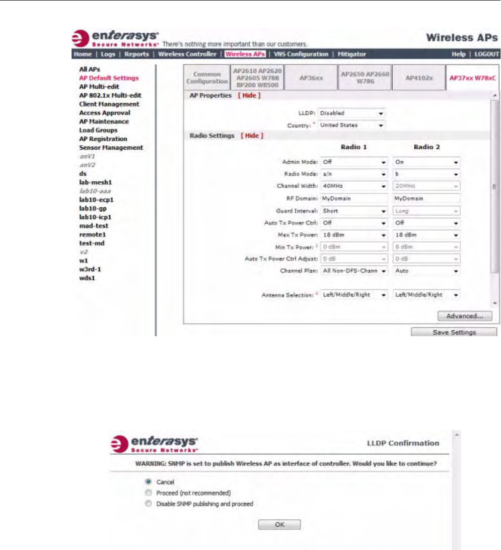
Configuring VLAN Tags for Wireless APs
3-102 Configuring the Wireless AP
3. ClicktheAP37xxW78xCtab.
4. IntheAPPropertiessection,dothefollowing:
–LLDP—ClicktoEnableorDisabletheWirelessAPfrombroadcastingLLDP
information.Thisoptionisdisabledbydefault.
IfSNMPisenabledontheEnterasysWirelessControllerandyouenableLLDP,theLLDP
Confirmationdialogisdisplayed.
–Selectoneofthefollowing:
‐Proceed(notrecommended)—SelectthisoptiontoenableLLDPandkeepSNMP
running,andthenclickOK.
‐DisableSNMPpublishing,andproceed—SelectthisoptiontoenableLLDPand
disableSNMP,andthenclickOK.
FormoreinformationonenablingSNMP,seetheEnterasysWirelessConvergence
SoftwareMaintenanceGuide.
DRAFT

Configuring VLAN Tags for Wireless APs
User Guide, V8.01 3-103
–AnnouncementInterval—IfLLDPisenabled,typehowoftentheWirelessAPadvertises
itsinformationbysendinganewLLDPpacket.Thisvalueismeasuredinseconds.
IftherearenochangestotheWirelessAPconfigurationthatimpacttheLLDP
information,theWirelessAPsendsanewLLDPpacketaccordingtothisschedule.
–AnnouncementDelay—IfLLDPisenabled,typetheannouncementdelay.Thisvalueis
measuredinseconds.IfachangetotheWirelessAPconfigurationoccurswhichimpacts
theLLDPinformation,theWirelessAPsendsanupdatedLLDPpacket.The
announcementdelayisthelengthoftimethatdelaysthenewpacketdelivery.The
announcementdelayhelpsminimizeLLDPpackettraffic.
–Country—Clickthecountryofoperation.Thisoptionisonlyavailablewithsome
licenses.
5. IntheRadioSettingssection,dothefollowingforeachradio:
–AdminMode—Forradios1and2,SelectOfftodisabletheradioorselectOntoenable
theradio:
–Radiomode—Clicktheradiomodeyouwanttoenable:
‐Radio1—a,a/n,orn‐strict.
‐Radio2—b,b/g,g,g/n,b/g/n,orn‐strict.
–ChannelWidth—Clickthechannelwidthfortheradio:
‐20MHz—Clicktoallow802.11nclientstousetheprimarychannel(20MHz)andnon‐
802.11nclients,beacons,andmulticaststousethe802.11b/gradioprotocols.
‐40MHz—Clicktoallow802.11nclientsthatsupportthe40MHzfrequencytouse
40MHz,20MHz,orthe802.11b/gradioprotocols.802.11nclientsthatdonotsupport
the40MHzfrequencycanuse20MHzorthe802.11b/gradioprotocolsandnon‐
802.11nclients,beacons,andmulticastsusethe802.11b/gradioprotocols.
‐Auto—Clicktoautomaticallyswitchbetween20MHzand40MHzchannelwidths,
dependingonhowbusytheextensionchannelis.
–RFDomain—TypeastringthatuniquelyidentifiesagroupofAPsthatcooperatein
managingRFchannelsandtransmissionpowerlevels.Themaximumlengthofthestring
is16characters.TheRFDomainisusedtoidentifyagroupofWirelessAPs.
–GuardInterval—Clickaguardinterval,LongorShort,whena40MHzchannelisused.
Enterasysrecommendsthatyouuseashortguardintervalinsmallrooms(forexample,a
smallofficespace)andalongguardintervalinlargerooms(forexample,aconference
hall).
–AutoTxPowerCtrl—ClicktoeitherenableordisableATPCfromtheAutoTxPower
Ctrldrop‐downlist.ATPCautomaticallyadaptstransmissionpowersignalsaccordingto
thecoverageprovidedbytheWirelessAPs.Afteraperiodoftime,thesystemwill
stabilizeitselfbasedontheRFcoverageofyourWirelessAPs.
–MaxTxPower—ClicktheappropriateTxpowerlevelfromtheMaxTXPowerdrop‐
downlist.ThevaluesintheMaxTXPowerdrop‐downareindBm.
Note: The Time to Live value cannot be directly edited. The Time to Live value is calculated as
four times the Announcement Interval value.
Note: Depending on the radio modes you select, some of the radio settings may not be available for
configuration.
DRAFT

Configuring VLAN Tags for Wireless APs
3-104 Configuring the Wireless AP
–MinTxPower—IfATPCisenabled,clicktheminimumTxpowerleveltowhichthe
rangeoftransmitpowercanbeadjusted:0to23(b/gorb/g/n)or24(aora/n)dBm.
Enterasysrecommendsthatyouselect0dBmtousetheentirerangeofpotentialTx
power.
–AutoTxPowerCtrlAdjust—IfATPCisenabled,clicktheTxpowerlevelthatcanbe
usedtoadjusttheATPCpowerlevelsthatthesystemhasassigned.Enterasys
recommendsthatyouuse0dBmduringyourinitialconfiguration.IfyouhaveanRFplan
thatrecommendsTxpowerlevelsforeachWirelessAP,comparetheactualTxpower
levelsyoursystemhasassignedagainsttherecommendedvaluesyourRFplanhas
provided.UsetheAutoTxPowerCtrlAdjustvaluetoachievetherecommendedvalues.
–ChannelPlan—IfACSisenabledyoucandefineachannelplanfortheWirelessAP.
Definingachannelplanallowsyoutolimitwhichchannelsareavailableforuseduringan
ACSscan.Forexample,youmaywanttoavoidusingspecificchannelsbecauseoflow
power,regulatorydomain,orradarinterference.
–AntennaSelection—Clicktheantenna,orantennacombination,youwanttoconfigure
onthisradio.
ForRadio1,clickoneofthefollowing:
‐Allchannels—ACSscansallchannelsforanoperatingchannelandreturnsboth
DFSandnon‐DFSchannels,ifavailable.
‐AllNon‐DFSChannels—ACSscansallnon‐DFSchannelsforanoperatingchannel.
ThisselectionisavailablewhenthereisatleastoneDFSchannelsupportedforthe
selectedcountry.
‐Custom—ToconfigureindividualchannelsfromwhichtheACSwillselectan
operatingchannel,clickConfigure.TheCustomChannelPlandialogdisplays.By
default,allchannelsparticipateinthechannelplan.Clicktheindividualchannelsyou
wanttoincludeinthechannelplan.Toselectcontiguouschannels,usetheShiftkey.
Toselectmultiple,non‐contiguouschannelsinthelist,usetheCTRLkey.ClickOKto
savetheconfiguration.
ForRadio2,clickoneofthefollowing:
‐3ChannelPlan—ACSwillscanthefollowingchannels:1,6,and11inNorth
America,and1,7,and13intherestoftheworld.
‐4ChannelPlan—ACSwillscanthefollowingchannels:1,4,7,and11inNorth
America,and1,5,9,and13intherestoftheworld.
‐Auto—ACSwillscanthedefaultchannelplanchannels:1,6,and11intheNorth
America,and1,5,9,and13intherestoftheworld.
‐Custom—IfyouwanttoconfigureindividualchannelsfromwhichtheACSwill
selectanoperatingchannel,clickConfigure.TheAddChannelsdialogisdisplayed.
Clicktheindividualchannelsyouwanttoaddtothechannelplanwhilepressingthe
CTRLkey,andthenclickOK.
6. Tomodifydefaultaccesspointadvancedsettings,clickAdvanced.TheAdvanceddialogis
displayed.
7. IntheAdvanceddialogAPPropertiessection,dothefollowing:
–PollTimeout—Typethetimeoutvalue,inseconds.TheWirelessAPusesthisvalueto
triggerre‐establishingthelinkwiththeEnterasysWirelessControllerifit(WirelessAP)
doesnotgetananswertoitspolling.Thedefaultvalueis10seconds.
DRAFT

Configuring VLAN Tags for Wireless APs
User Guide, V8.01 3-105
–RemoteAccess—ClicktoEnableorDisabletelnetorSSHaccesstotheWirelessAP.
–Location‐basedservice—ClicktoEnableorDisablelocation‐basedserviceonthis
WirelessAP.Location‐basedserviceallowsyoutousethisWirelessAPwithanAeroScout
solution.
–Maintainclientsessionineventofpollfailure—ClicktoEnableorDisable(ifusinga
bridgedatAPVNS)iftheAPshouldremainactiveifalinklosswiththecontroller
occurs.Thisoptionisenabledbydefault.
–Restartserviceintheabsenceofcontroller—ClicktoEnableorDisable(ifusinga
bridgedatAPVNS)toensuretheWirelessAPs’radioscontinueprovidingserviceifthe
WirelessAP’sconnectiontotheEnterasysWirelessControllerislost.Ifthisoptionis
enabled,itallowstheWirelessAPtostartabridgedatAPVNSevenintheabsenceofa
EnterasysWirelessController.
–Usebroadcastfordisassociation—ClicktoEnableorDisableifyouwanttheWireless
APtousebroadcastdisassociationwhendisconnectingallclients,insteadof
disassociatingeachclientonebyone.ThiswillaffectthebehavioroftheAPunderthe
followingconditions:
‐IftheWirelessAPispreparingtorebootortoenteroneofthespecialmodes(DRM
initialchannelselection).
‐IfaBSSIDisdeactivatedorremovedontheWirelessAP.
Thisoptionisdisabledbydefault.
–RealCapture—ClickStarttostartrealcaptureserverontheAP.Thisfeaturecanbe
enabledforeachAPindividually.Statisticsarecapturedusinganexternalconnectiontoa
WindowsWireSharkclient.InWireshark,byselectingtheremoteAPs’IPaddressand
nullauthentication,thewiredandenabledwirelessinterfacesarelistedasavailablefor
capture.Defaultcaptureservertimeoutissetto300secondsandthemaximum
configurabletimeoutis1hour.CapturestatisticsarefoundontheActiveWirelessAPs
report(seeViewingStatisticsforWirelessAPs).
8. IntheAdvanceddialogRadioSettingssection,dothefollowing:
–DTIM—TypethedesiredDTIM(DeliveryTrafficIndicationMessage)period—the
numberofbeaconintervalsbetweentwoDTIMbeacons.Toensurethebestclientpower
savings,usealargenumber.Forexample,5.Useasmallnumbertominimizebroadcast
andmulticastdelay.Thedefaultvalueis5.
–BeaconPeriod—Typethedesiredtime,inmilliseconds,betweenbeacontransmissions.
Thedefaultvalueis100milliseconds.
–RTS/CTS—Typethepacketsizethreshold,inbytes,abovewhichthepacketwillbe
precededbyanRTS/CTS(RequesttoSend/CleartoSend)handshake.Thedefaultvalueis
2346,whichmeansallpacketsaresentwithoutRTS/CTS.Reducethisvalueonlyif
necessary.
–Frag.Threshold—Typethefragmentsizethreshold,inbytes,abovewhichthepackets
willbefragmentedbytheAPpriortotransmission.Thedefaultvalueis2346,which
meansallpacketsaresentunfragmented.Reducethisvalueonlyifnecessary.
–Max%ofnon‐unicasttrafficperBeaconperiod—Enterthemaximumpercentageof
timethattheAPwilltransmitnon‐unicastpackets(broadcastandmulticasttraffic)for
eachconfiguredBeaconPeriod.Foreachnon‐unicastpackettransmitted,thesystem
calculatestheairtimeusedbyeachpacketanddropsallpacketsthatexceedthe
Note: If you are configuring session availability, the Poll Timeout value should be 1.5 to 2 times of
Detect link failure value on AP Properties screen. For more information, see “Session Availability”
on page 11-9.
DRAFT

Configuring VLAN Tags for Wireless APs
3-106 Configuring the Wireless AP
configuredmaximumpercentage.Byrestrictingnon‐unicasttraffic,youlimittheimpact
ofbroadcastsandmulticastsonoverallsystemperformance.
–MaximumDistance—Enteravaluefrom100to15,000metersthatidentifiesthe
maximumlinkdistancebetweenAPsthatparticipateinaWDS.Thisvalueensuresthat
theacknowledgementofcommunicationbetweenAPsdoesnotexceedthetimeoutvalue
predefinedbythe802.11standard.Thedefaultvalueis100meters.Ifthelinkdistance
betweenAPsisgreaterthan100meters,configurethemaximumdistanceupto15,000
meterssothatthesoftwareincreasesthetimeoutvalueproportionallywiththedistance
betweenAPs.
Donotchangethedefaultsettingfortheradiothatprovidesserviceto802.11clientsonly.
–DynamicChannelSelection—Clickoneofthefollowing:
‐Off—DisablesDCS.
‐MonitorMode—IftrafficornoiselevelsexceedtheconfiguredDCSthresholds,an
alarmistriggeredandaninformationlogisgenerated.
‐ActiveMode—IftrafficornoiselevelsexceedtheconfiguredDCSthresholds,an
alarmistriggeredandaninformationlogisgenerated.Inaddition,theWirelessAP
willceaseoperatingonthecurrentchannelandACSisemployedtoautomatically
selectanalternatechannelfortheWirelessAPtooperateon.
–DCSNoiseThreshold—IfDCSisenabled,typethenoiseinterferencelevel,measuredin
dBm,afterwhichACSwillscanforanewoperatingchannelfortheWirelessAPifthe
thresholdisexceeded.
–DCSChannelOccupancyThreshold—IfDCSisenabled,typethechannelutilization
level,measuredasapercentage,afterwhichACSwillscanforanewoperatingchannel
fortheWirelessAPifthethresholdisexceeded.
–DCSUpdatePeriod—IfDCSisenabled,typethetime,measuredinminutesthat
determinestheperiodduringwhichtheWirelessAPaveragestheDCSNoiseThreshold
andDCSChannelOccupancyThresholdmeasurements.Ifeitheroneofthesethresholds
isexceeded,thentheWirelessAPwilltriggerACS.
–Preamble—Clickapreambletypefor11b‐specific(CCK)rates:Short,Long,orAuto.The
recommendedvalueisAuto.ClickShortifyouaresurethatthereisnopre‐11bAPora
clientinthevicinityofthisAP.ClickLongifcompatibilitywithpre‐11bclientsisrequired.
–ProtectionMode—Clickaprotectionmode:None,Auto,orAlways.Thedefaultand
recommendedsettingisAuto.ClickNoneif11bAPsandclientsarenotexpected.Click
Alwaysifyouexpectmany11b‐onlyclients.
–ProtectionRate—Clickaprotectionrate:1,2,5.5,or11Mbps.Thedefaultand
recommendedsettingis11.Onlyreducetherateiftherearemany11bclientsinthe
environmentorifthedeploymenthasareaswithpoorcoverage.Forexample,rateslower
than11Mbpsarerequiredtoensurecoverage.
–ProtectionType—Clickaprotectiontype:CTSOnlyorRTSCTS.Thedefaultand
recommendedsettingisCTSOnly.ClickRTSCTSonlyifan11bAPthatoperatesonthe
samechannelisdetectedintheneighborhood,oriftherearemany11b‐onlyclientsinthe
environment.
–MinBasicRate—Foreachradio,clicktheminimumdataratethatmustbesupportedby
allstationsinaBSS:1,2,5.5,or11Mbpsfor11band11b+11gmodes.Click1,2,5.5,6,11,
12,or24Mbpsfor11g‐onlymode.Click6,12,or24Mbpsfor11amode.
DRAFT

Modifying a Wireless AP’s Properties Based on a Default AP Configura-
User Guide, V8.01 3-107
9. IntheAdvanceddialog11nSettingssection,dothefollowing:
–ProtectionMode—Clickaprotectionmode:None,Auto,orAlways.Thedefaultand
recommendedsettingisAuto.ClickNoneif11bAPsandclientsarenotexpected.Click
Alwaysifyouexpectmany11b‐onlyclients.
–ProtectionType—Clickaprotectiontype,CTSOnlyorRTS‐CTS,whena40MHz
channelisused.Thisprotectshighthroughputtransmissionsonextensionchannelsfrom
interferencefromnon‐11nAPsandclients.
–40MHzProt.ChannelOffset—Selecta20MHzchanneloffsetifthedeploymentisusing
channelsthatare20MHzapart(forexample,usingchannels1,5,9,and13)ora25MHz
channeloffsetifthedeploymentisusingchannelsthatare25MHzapart(forexample,
usingchannels1,6,and11).
–40MHzChannelBusyThreshold—Typetheextensionchannelthresholdpercentage,
whichifexceeded,willdisabletransmissionsontheextensionchannel(40MHz).
–AggregateMSDUs—ClickanaggregateMSDUmode:EnabledorDisabled.Aggregate
MSDUincreasesthemaximumframetransmissionsize.
–AggregateMPDUs—ClickanaggregateMPDUmode:EnabledorDisabled.Aggregate
MPDUprovidesasignificantimprovementinthroughput.
–AggregateMPDUMaxLength—TypethemaximumlengthoftheaggregateMPDU.The
valuerangeis1024‐65535bytes.
–Agg.MPDUMax#ofSub‐frames—Typethemaximumnumberofsub‐framesofthe
aggregateMPDU.Thevaluerangeis2‐64.
–ADDBASupport—ClickanADDBAsupportmode:EnabledorDisabled.ADDBA,or
blockacknowledgement,providesacknowledgementofagroupofframesinsteadofa
singleframe.ADDBASupportmustbeenabledifAggregateMPDUisenabled.
–LDPC—ClickanLDPCmode:EnabledorDisabled.LDPCincreasesthereliabilityofthe
transmissionresultingina2dBincreasedperformancecomparedtotraditional11n
coding.
–STBC—ClickanSTBCmode:EnabledorDisabled.STBCisasimpleopenlooptransmit
diversityscheme.Whenenabled,STBCconfigurationis2x1(onespatialstreamsplitinto
twospace‐timestreams).TXBFwilloverrideSTBCifbothareenabledforsinglestream
rates.
–TXBF—ClickanTXBFmode:EnabledorDisabled.TxBeamFormingfocuses
transmissionbeamsdirectlyattheintendedreceiverwhilereducingtheoverall
interferencegeneratedbythetransmitter.
10. ClickClose.TheAdvanceddialogisclosed.
11. Tosaveyourchanges,clickSaveSettings.
Modifying a Wireless AP’s Properties Based on a Default AP
Configuration
IfyouhaveaWirelessAPthatisalreadyconfiguredwithitsownsettings,butwouldlikethe
WirelessAPtoberesettousethesystem’sdefaultAPsettings,usetheResettoDefaultsfeature
ontheAPPropertiestab.
To Configure a Wireless AP with the System’s Default AP Settings:
1. Fromthetopmenu,clickWirelessAPs.TheWirelessAPscreenisdisplayed.
DRAFT

Modifying the Wireless AP’s Default Setting Using the Copy to Defaults Feature
3-108 Configuring the Wireless AP
2. IntheWirelessAPlist,clicktheWirelessAPwhosepropertiesyouwanttomodify.TheAP
PropertiestabdisplaysWirelessAPinformation.
3. TohavetheWirelessAPinheritthesystem’sdefaultAPsettings,clickResettoDefaults.A
pop‐updialogaskingyoutoconfirmtheconfigurationchangeisdisplayed.
4. ToconfirmresettingtheWirelessAPtothedefaultsettings,clickOK.
Modifying the Wireless AP’s Default Setting Using the Copy to
Defaults Feature
Youcanmodifythesystem’sdefaultAPsettingsbyusingtheCopytoDefaultsfeatureontheAP
Propertiestab.ThisfeatureallowsthepropertiesofanalreadyconfiguredWirelessAPtobecome
thesystem’sdefaultWirelessAPsettings.
To Modify the System’s Default AP Settings Based on an Already Configured AP:
1. Fromthetopmenu,clickWirelessAPs.TheWirelessAPscreenisdisplayed.
2. IntheWirelessAPlist,clicktheWirelessAPwhosepropertiesyouwanttobecomethe
system’sdefaultAPsettings.TheAPPropertiestabisdisplayed.
3. Ifapplicable,modifytheWirelessAP’sproperties.Formoreinformation,see“Configuringa
WirelessAP’sProperties”onpage 3‐31.
4. TomakethisWirelessAP’sconfigurationbethesystem’sdefaultAPsettings,clickCopyto
Defaults.Apop‐updialogaskingyoutoconfirmtheconfigurationchangeisdisplayed.
5. Toconfirmresettingthesystem’sdefaultWirelessAPsettings,clickOK.
Configuring Multiple Wireless APs Simultaneously
InadditiontoconfiguringWirelessAPsindividually,youcanalsoconfiguremultipleWireless
APssimultaneouslybyusingtheAPMulti‐editfunction.ConfiguringWirelessAPs
simultaneouslyissimilartomodifyingthesystem’sdefaultAPsettingsorindividualWireless
APs.
WhenselectingwhichWirelessAPstoconfiguresimultaneously,youcanusethefollowing
criteria:
•Sel
ecttheWirelessAPsbyhardwaretype
•SelecttheWirelessAPsindividually
YoucanselectmultiplehardwaretypesandindividualWirelessAPsbypressingtheCtrlkeyand
selectingthehardwaretypesandspecificWirelessAPs.
WhenyouconfiguremultipleWirelessAPsusingtheAPMulti‐editscreen,itisimportanttonote
thatforsomeWirelessAPsettingstobeavailableforconfiguration,otherWirelessAPsettings
mustbeenabledorconfiguredfirst.
Caution: If you reset an AP to defaults, its Search List will be deleted, regardless of the settings in
Common Configuration.
Note: Only settings and options supported by all of the currently selected hardware types are
available for configuring.
DRAFT
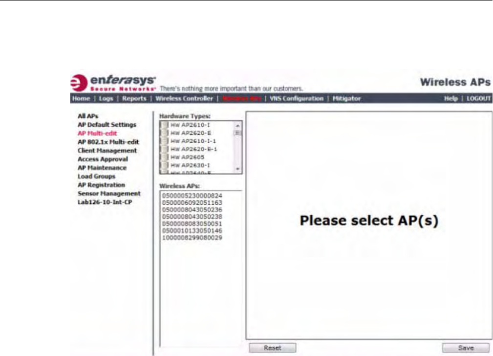
Configuring Multiple Wireless APs Simultaneously
User Guide, V8.01 3-109
To Configure Wireless APs Simultaneously:
1. Fromthetopmenu,clickWirelessAPs.TheWirelessAPscreenisdisplayed.
2. Intheleftpane,clickAPMulti‐edit.
3. Dooneofthefollowing:
–IntheHardwareTypeslist,clickoneormoreWirelessAPhardwaretypes.
DRAFT
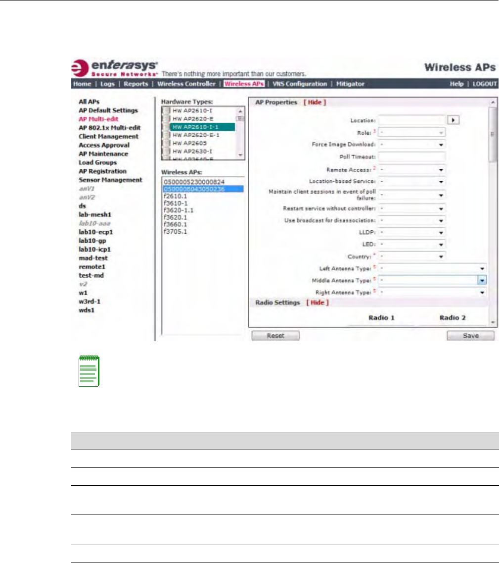
Configuring Multiple Wireless APs Simultaneously
3-110 Configuring the Wireless AP
–IntheWirelessAPslist,clickoneormoreWirelessAPstoedit.ToclickmultipleWireless
APs,clicktheAPsfromthelistwhilepressingtheCTRLkey.TheAPprofilepage
displays.
Note: When using the Multi-edit function, any box or option that is not explicitly modified will not be
changed by the update.
The Wireless APs shown in the Wireless APs list can be from any version of the software. Only
attributes that are common between software versions will be available. Attempting to set an
attribute that does not apply for an AP will not abort the multi-edit operation.
Field/Button Description
Hardware Types The Wireless AP hardware model.
Wireless APs The name assigned to the Wireless AP.
AP Properties Formoreinformation,see“ConfiguringaWirelessAP’s
Properties” on page 3-31.
Radio Settings Formoreinformation,see“ConfiguringWirelessAPRadio
Properties”onpage 3‐36.
Static Configuration
HWC Search List Click one of the following:
•Clear search list — Click to clear previously assigned
Enterasys Wireless Controllers that were configured to control
this Wireless AP.
•Re-configure search list — Click to assign Enterasys
Wireless Controllers to control this Wireless AP. This causes
the Add box to become available.
DRAFT

Configuring Co-located APs in Load Balance Groups
User Guide, V8.01 3-111
Configuring Co-located APs in Load Balance Groups
YoucanconfigureAPsthatareco‐locatedinanopenarea,suchasaclassroom,aconferencehall,
oranentrancelobby,toactasaloadbalancegroup.Loadbalancingdistributesclientsacrossthe
co‐locatedAPsthataremembersoftheloadbalancegroup.Theco‐locatedAPsshouldprovide
thesameSSID,haveLine‐of‐Sight(LoS)betweeneachother,andbedeployedonmultiple
channelswithoverlappingcoverage.
YoumustassignanAP’sradiototheloadbalancegroupfortheclientdistributiontooccur.Load
balancingoccursonlyamongtheassignedAPradiosoftheloadbalancegroup.Eachradiocanbe
assignedonlytooneloadbalancegroup.MultipleradiosonthesameAPdonothavetobeinthe
sameloadbalancegroup.TheradiosthatyouassigntotheloadbalancegroupmustbeonAPs
thatarecontrolledbythesameEnterasysWirelessController.
TheloadbalancegroupusesoneormoreWLANservicesforallAPsassignedtotheloadbalance
group.Youcanconfiguretwotypesofloadbalancegroups:
Youcanconfiguretwotypesofloadgroups:
Add box Enter the IP address of the Enterasys Wireless Controller that will
control this Wireless AP.
This box is available only if you selected Re-configure search
list when configuring the search list.
Click the Add button to add the IP address to the list. Repeat to
add additional Enterasys Wireless Controllers. The maximum is
three Enterasys Wireless Controllers.
Click Up and Down to modify the order of the Enterasys Wireless
Controllers.
The Wireless AP is successful when it finds a Enterasys Wireless
Controller that will allow it to register.
This feature allows the Wireless AP to bypass the discovery
process. If the HWC Search List is not populated, the Wireless
AP will use SLP unicast/multicast, DNS, or DHCP vendor option
43 to discover a Enterasys Wireless Controller. For the initial
Wireless AP deployment, it is necessary to use one of the
described options in “Discovery and Registration Overview” on
page 3-10.
Tunnel MTU Enter a static MTU value, from 600 to 1500. If the Enterasys
wireless software cannot discover the MTU size, it enforces the
static MTU size. Set the MTU size to allow the source to reduce
the packet size and avoid the need to fragment data packets in the
tunnel.
WLAN Assignments
WLAN Assignments Fromthedrop‐downlist,clickoneofthefollowing:
•Clear WLAN list — Click to clear previously assigned WLAN
services of the Wireless APs.
•Re-configure WLAN list — Click to assign WLAN services to
the Wireless APs.
In the Radio 1 and Radio 2 columns, select the Wireless AP
radios that you want to assign for each WLAN service.
Save Clicktosaveyourchanges.
Field/Button Description
DRAFT

Configuring Co-located APs in Load Balance Groups
3-112 Configuring the Wireless AP
•ClientBalancingloadgroup–preformsloadbalancingbasedonthenumberofclientsacross
allAPsinthegroupandonlyfortheWLANsassignedtotheloadgroup.Thisisdifferent
fromloadcontrolintheRadioPreferencegroup—loadcontrolAPsmakedecisionsin
isolationfromeachother.
•RadioPreferenceloadgroup–performsbandpreferencesteeringandloadcontrol.Band
preferencesteeringisamechanismtomove11a‐capableclientstothe11aradioontheAP,
relievingcongestiononthe11gradio.Nobalancingisdonebetweenthe11aand11gradios.
Loadcontrolisdisabledbydefault.Aradioloadgroupexecutesbandpreferencesteering
and/orloadcontrolacrosstheradiosoneachAPinthegroup.EachAPbalancesinisolation
fromtheotherAPs,butallAPsintheloadgrouphavethesameconfigurationrelatedtothe
bandpreferenceandloadcontrol.
ClientbalancingontheEnterasysWirelessControllerisAP‐centricandrequiresnoinputfromthe
client.TheAPradiosintheclientbalancegroupshareinformationwithsecure(AES)SIAPP
(SiemensInter‐APProtocol)messagingusingmulticastonthewirednetwork.AllAPsinaclient
balancegroupmustbeinthesameSIAPPclustertoensurethateachAPcanreachallotherAPsin
theclientbalancegroupoverthewiredsubnet.IftheAPsinaclientbalancegrouparenotinsame
SIAPPcluster,clientbalancingwillhappenindependentlywithinthesubgroupsdefinedby
SIAPPclusters.
Thebenefitsofconfiguringyourco‐locatedAPsthatarecontrolledbythesameEnterasysWireless
Controllerasaclientbalancegrouparethefollowing:
•ResourcesharingofthebalancedAP
• Efficientuseofthedeployed2.4and5GHzchannels
•Reduceclientinterferencebydistributingclientsondifferentchannels
•Scalable802.11deployment:ifmoreclientsneedtobeservedinthearea,additionalAPscan
bedeployedonanewchannel
Youcanassignamaximumof32APstoaclientbalancegroup.Table 3‐25liststhemaximum
numberofloadbalancegroupsforeachEnterasysWirelessController.
Currently,thefollowingWirelessAPmodelssupportloadbalancegroups:
•AP36
05
•AP3610
•AP3620
•AP3630(infitmodeonly)
•AP3640(infitmodeonly)
•AP3660
Table 3-25 Maximum Number of Load Balance Groups
Enterasys Wireless Controller Number of load balance groups
C20 8
C4110 32
C5100 64
C25 8
V2110 32
DRAFT