Chantry Networks APXXX1 HiPATH WIRELESS ACCESS POINT (AP) User Manual
Chantry Networks Inc. (a Siemens Company) HiPATH WIRELESS ACCESS POINT (AP)
UserManual.wiki
>
Chantry Networks
>
APXXX1 User Manual
>
User Manual
Contents
1.
USERS MANUAL
2.
USERS MANUAL 1
3.
USERS MANUAL 2
4.
Users Manual
5.
users manual
6.
User Manual
User Manual
Navigation menu
Upload a User Manual
Namespaces
Wiki Guide
HTML
PDF
Info
Views
User Manual
Discussion / Help
Navigation
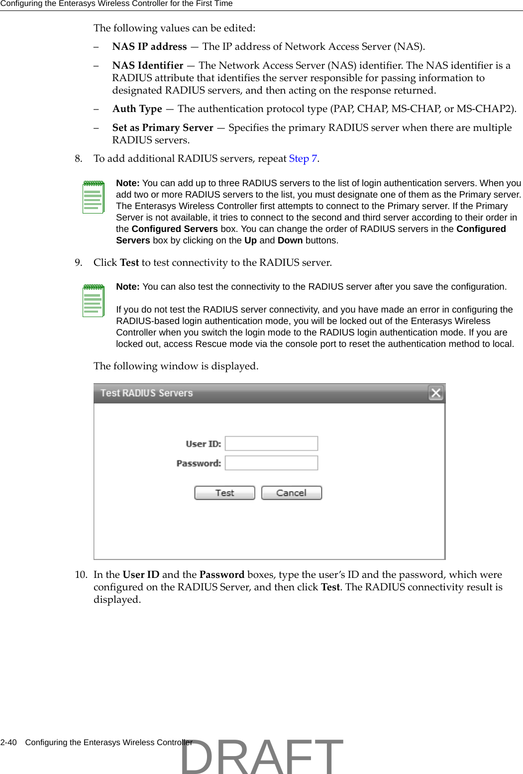
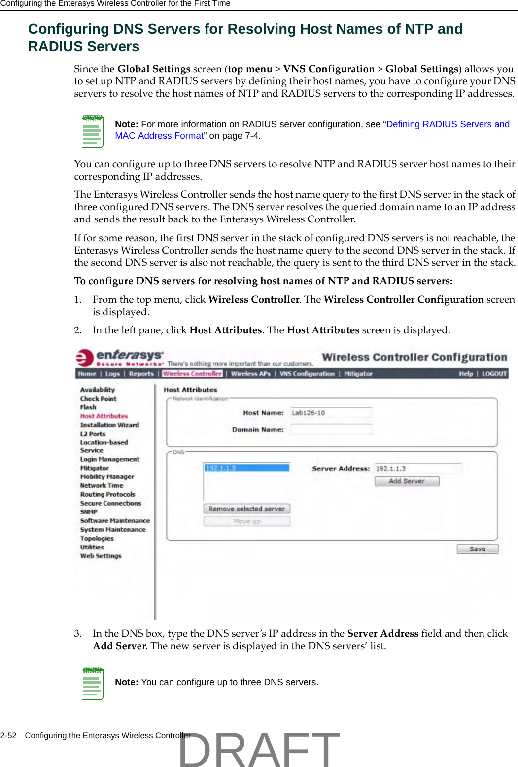
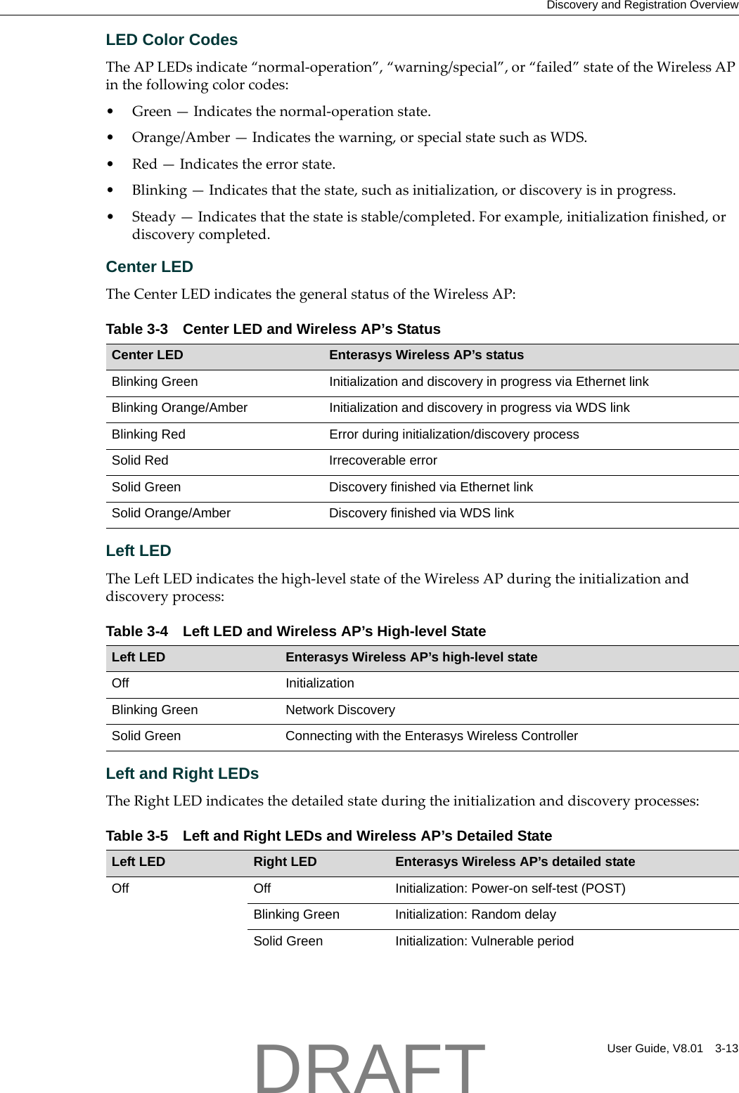
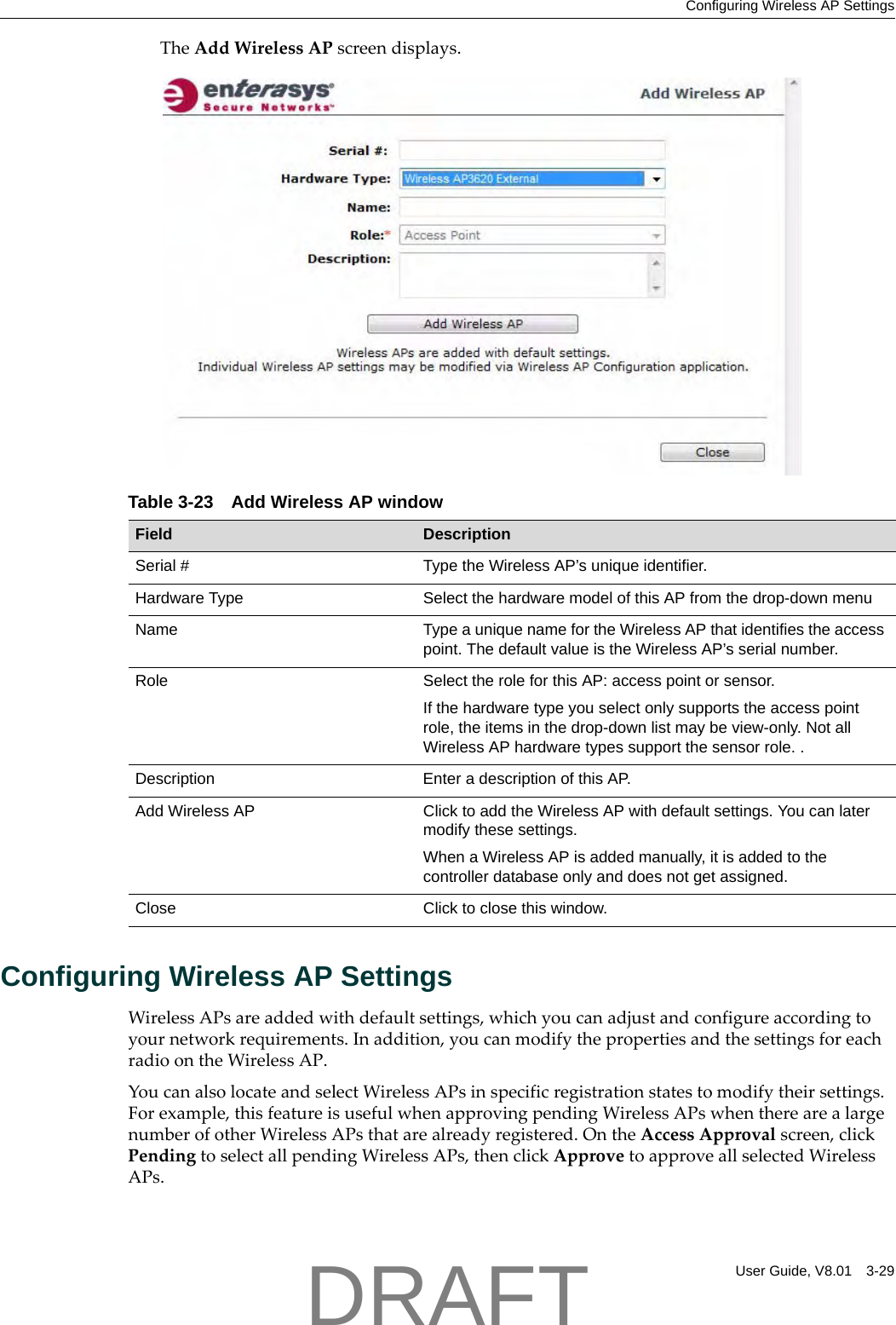
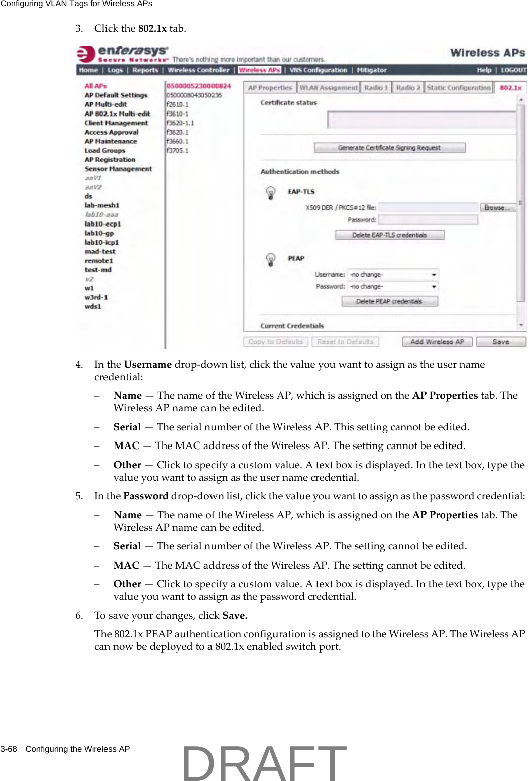
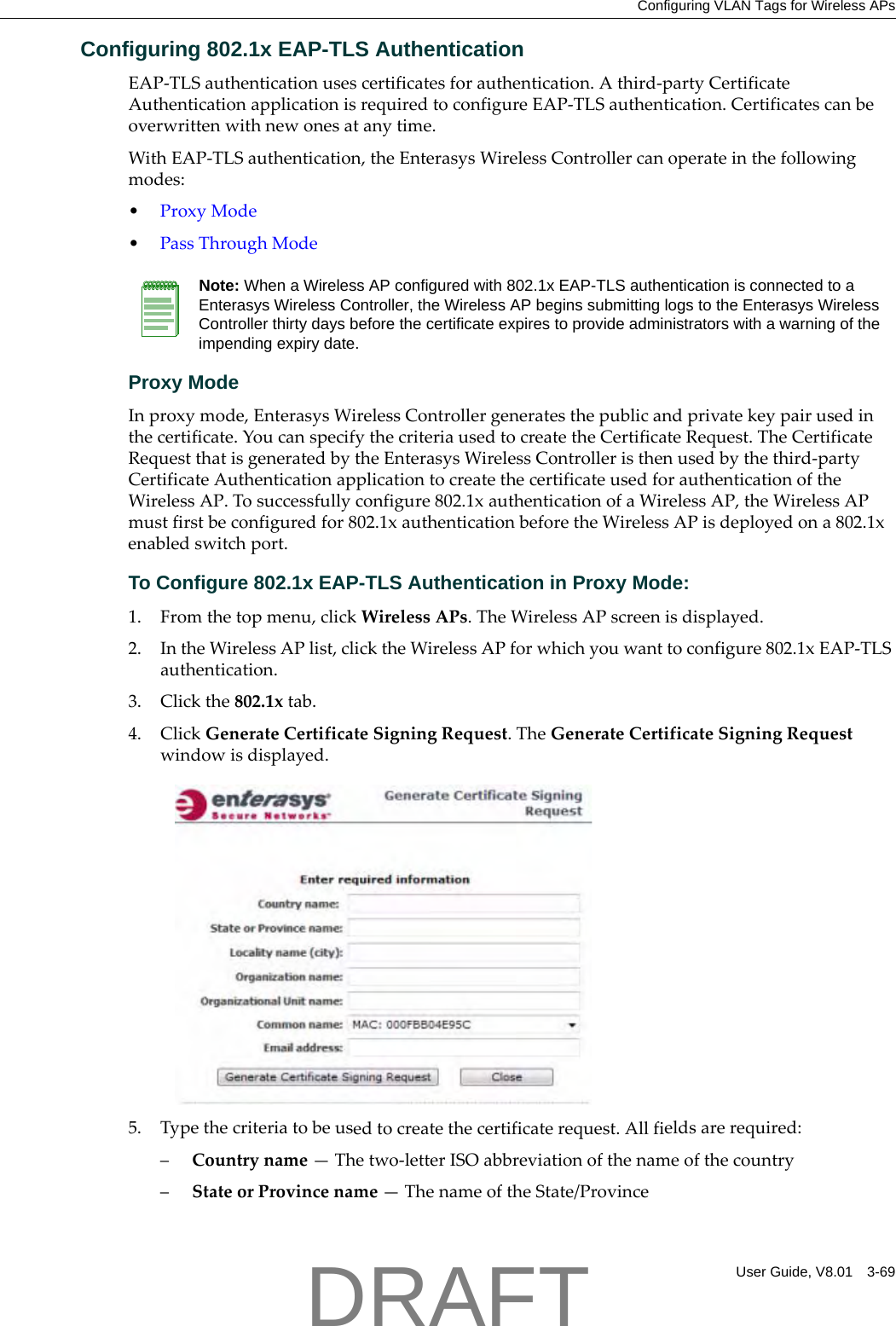
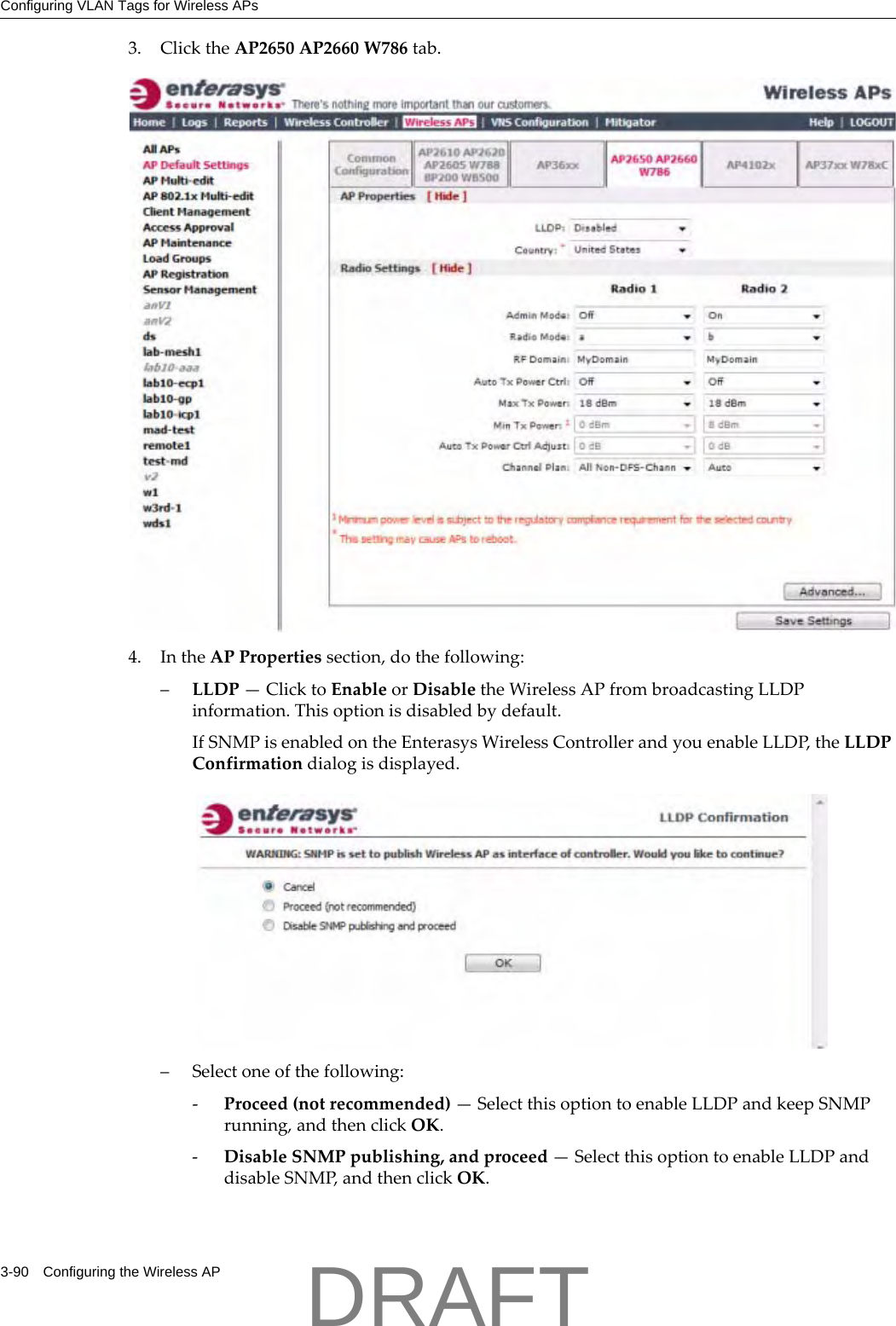
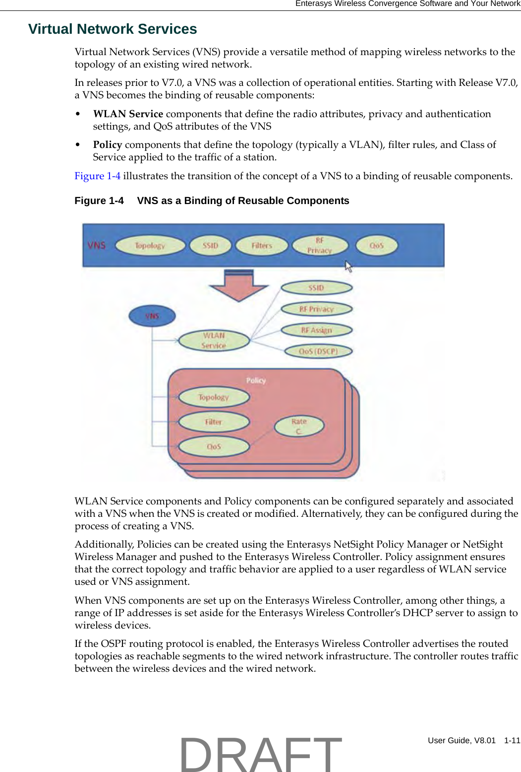
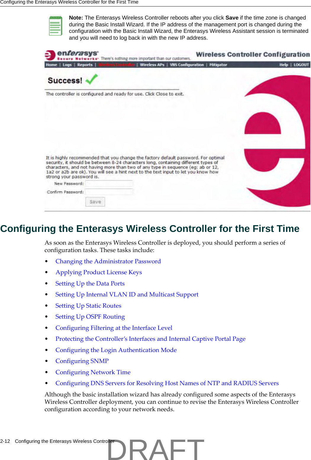
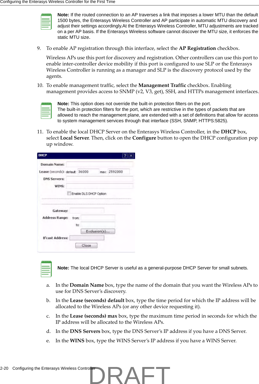
![Additional DocumentationUser Guide, V8.01 xvii•Monospace fontisusedincodeexamplesandtoindicatetextthatyoutype.Forexample:Typehttps://<hwc-address>[:mgmt-port]•Thefollowingnotesareusedtodrawyourattentiontoadditionalinformation:Additional DocumentationToaccessrelatedinformation,seetheEnterasysWirelessConvergenceSoftwareUserGuide.EnterasysWirelessControllerdocumentationisavailableat:https://extranet.enterasys.com/downloadswww.siemens.com/automation/service&supportGetting HelpForadditionalsupportrelatedtotheproductorthisdocument,contactEnterasysNetworksusingoneofthefollowingmethods:BeforecontactingEnterasysNetworksfortechnicalsupport,havethefollowinginformationready:•YourEnterasysNetworksservicecontractnumber•Adescriptionofthefailure•Adescriptionofanyaction(s)alreadytakentoresolvetheproblem(forexample,changingmodeswitchesorrebootingtheunit)•TheserialandrevisionnumbersofallinvolvedEnterasysNetworksproductsinthenetwork•Adescriptionofyournetworkenvironment(suchaslayout,cabletype,otherrelevantenvironmentalinformation)•Networkloadandframesizeatthetimeoftrouble(ifknown)Note: Notes identify useful information, such as reminders, tips, or other ways to perform a task.Caution: Cautionary notes identify essential information, which if ignored can adversely affect the operation of your equipment or software.Warning: Warning notes identify essential information, which if ignored can lead to personal injury or harm.World Wide Web www.enterasys.com/supportPhone 1-800-872-8440 (toll-free in U.S. and Canada) or 1-978-684-1000To find the Enterasys Networks Support toll-free number in your country: www.enterasys.com/supportInternet mail support@enterasys.comTo expedite your message, type Enterasys Wireless in the subject lineTo send comments concerning this document to the Technical Publications Department:techpubs@www.enterasys.comPlease include the document part number in your email message.DRAFT](https://usermanual.wiki/Chantry-Networks/APXXX1.User-Manual/User-Guide-1621739-Page-19.png)

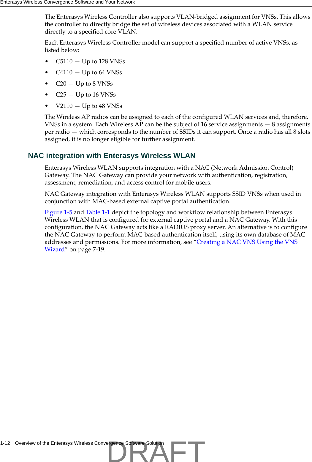

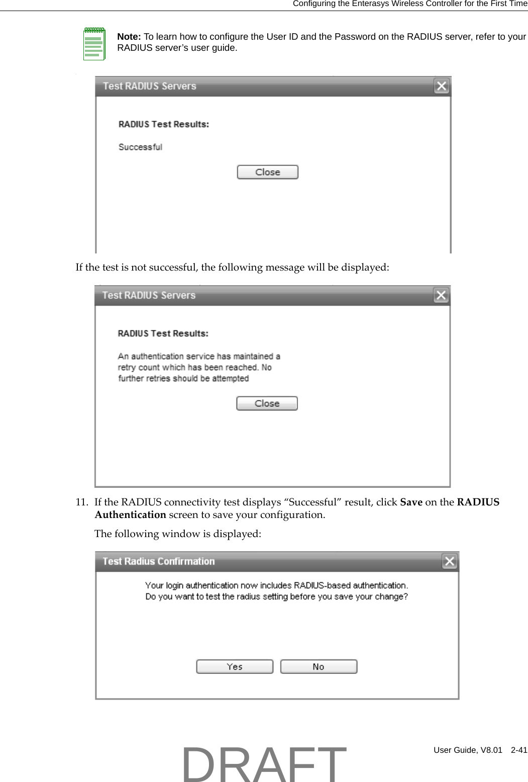
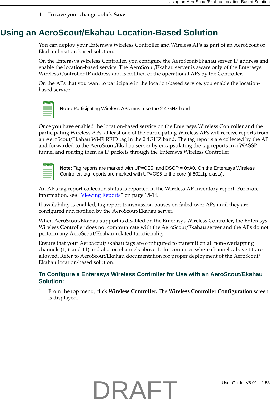
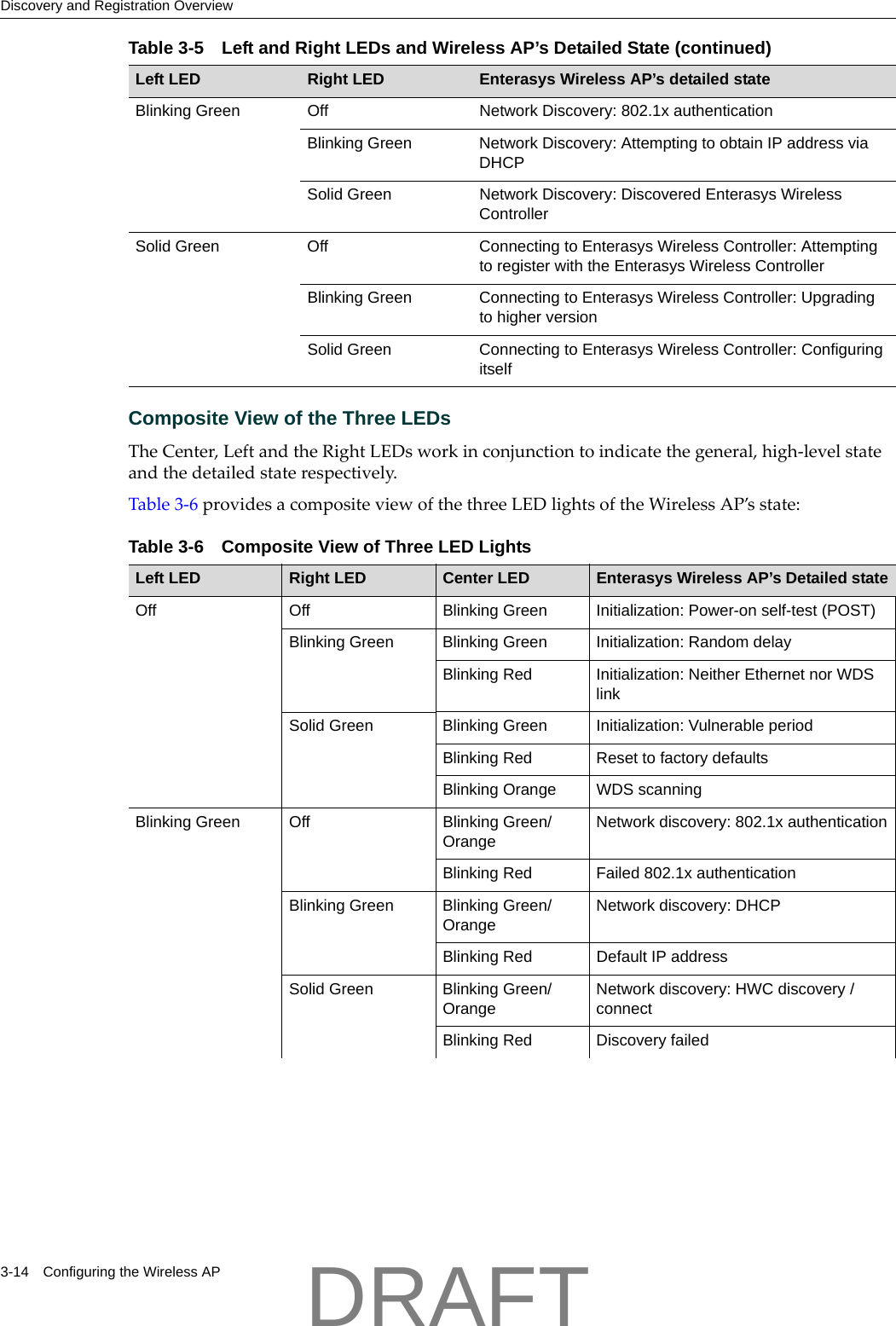
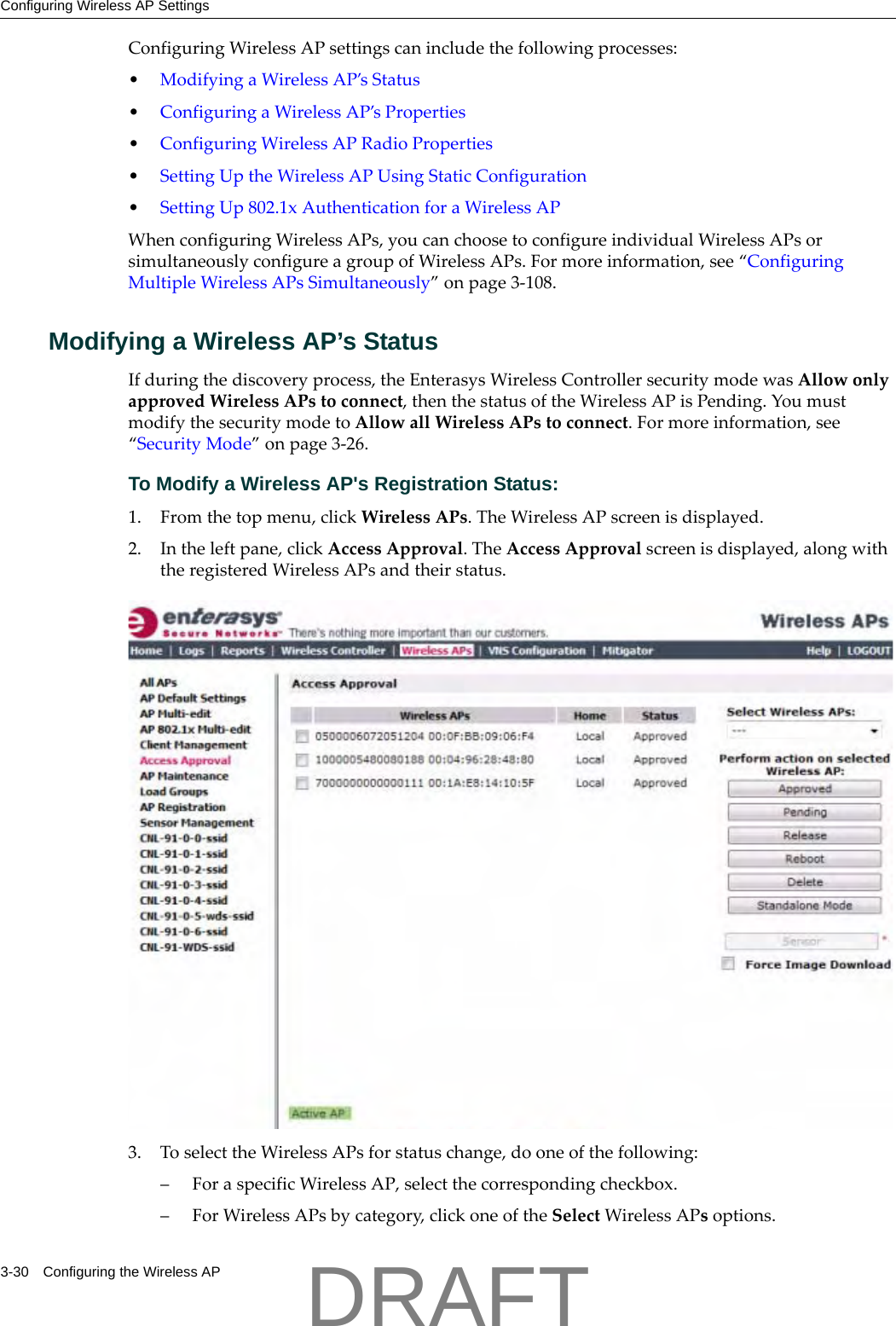
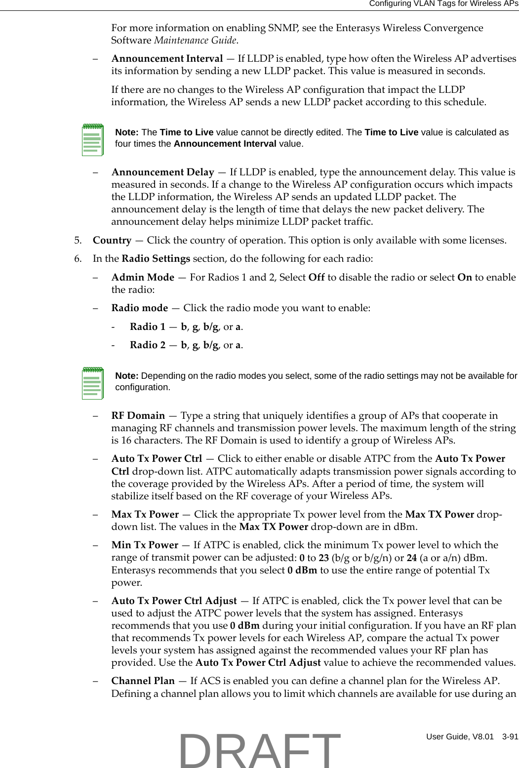
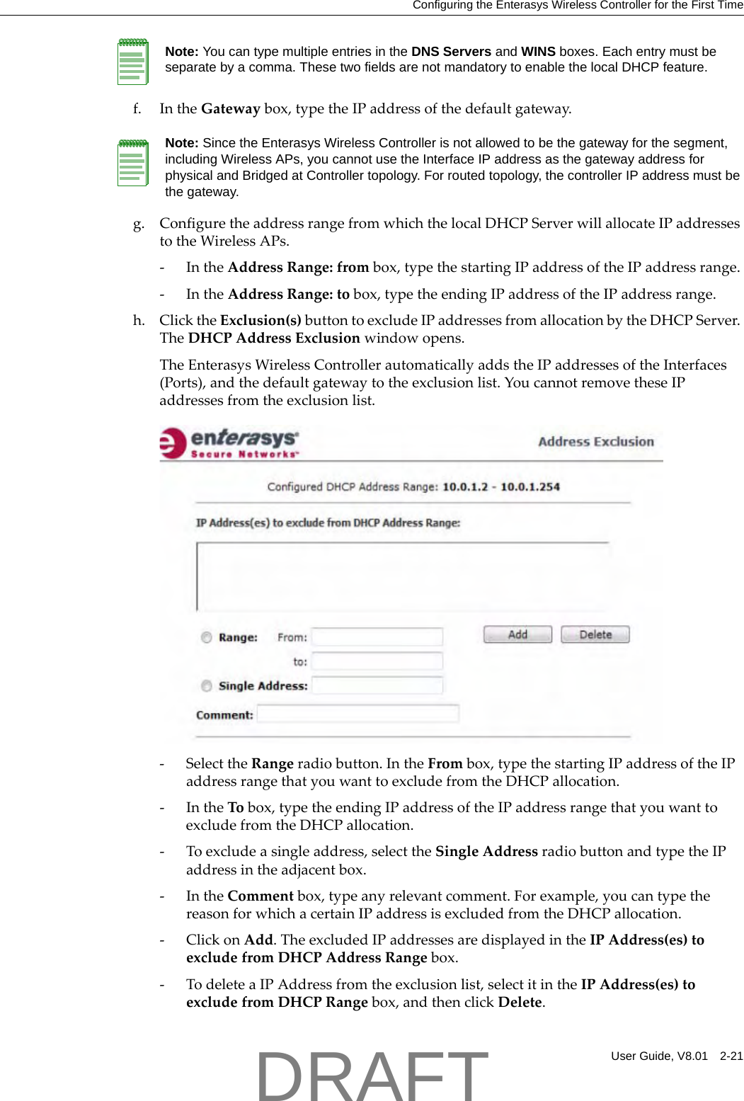
![2-2 Configuring the Enterasys Wireless Controller– Configurethetimezone.BecausechangingthetimezonerequiresrestartingtheEnterasysWirelessController,EnterasysrecommendsthatyouconfigurethetimezoneduringtheinitialinstallationandconfigurationoftheEnterasysWirelessControllertoavoidnetworkinterruptions.Formoreinformation,see“ConfiguringNetworkTime”onpage 2‐48.–Applyanactivationkeyfile.Ifanactivationkeyisnotapplied,theEnterasysWirelessControllerfunctionswithsomefeaturesenabledindemonstrationmode.Notallfeaturesareenabledindemonstrationmode.Forexample,mobilityisnotenabledandcannotbeused.5. ConfiguretheEnterasysWirelessControllerforremoteaccess:–Setupanadministrationstation(laptop)onsubnet192.168.10.0/24.Bydefault,theEnterasysWirelessControllerʹsManagementinterfaceisconfiguredwiththestaticIPaddress192.168.10.1.– ConfiguretheEnterasysWirelessController’smanagementinterface.– Configurethedatainterfaces.–SetuptheEnterasysWirelessControlleronthenetworkbyconfiguringthephysicaldataports.– Configuretheroutingtable.– ConfigurestaticroutesorOSPFparameters,ifappropriatetothenetwork.Formoreinformation,see“ConfiguringtheEnterasysWirelessControllerfortheFirstTime”onpage 2‐12.6. Configurethetraffictopologiesyournetworkmustsupport.TopologiesrepresenttheController’spointsofnetworkattachment,andthereforeVLANsandportassignmentsneedtobecoordinatedwiththecorrespondingnetworkswitchports.Formoreinformation,see“ConfiguringaBasicTopology”onpage 4‐2.7. Configurepolicies.Policiesaretypicallyboundtotopologies.Policyapplicationassignsusertraffictothecorrespondingnetworkpoint.– Policiesdefineuseraccessrights(filteringorACL)–Policesreferenceuserʹsratecontrolprofile.Formoreinformation,see“ConfiguringPolicies”onpage 5‐1.8. ConfigureWLANservices.–DefineSSIDandprivacysettingsforthewirelesslink.–SelectthesetofAPs/Radiosonwhichtheserviceispresent.– Configurethemethodofcredentialauthenticationforwirelessusers(None,InternalCP,ExternalCP,GuestPortal,802.1x[EAP])Formoreinformation,see“ConfiguringWLANServices”onpage 6‐1.9. CreatetheVNSs.Caution: Whenever the licensed region changes on the Enterasys Wireless Controller, all Wireless APs are changed to Auto Channel Select to prevent possible infractions to local RF regulatory requirements. If this occurs, all manually configured radio channel settings will be lost.Installing the new license key before upgrading will prevent the Enterasys Wireless Controller from changing the licensed region, and in addition, manually configured channel settings will be maintained. For more information, see the Enterasys Wireless Convergence Software Maintenance Guide.DRAFT](https://usermanual.wiki/Chantry-Networks/APXXX1.User-Manual/User-Guide-1621739-Page-42.png)

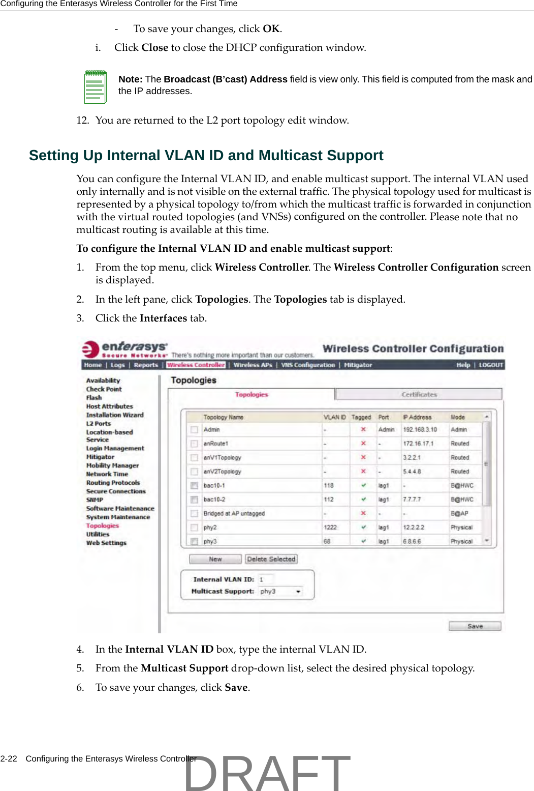
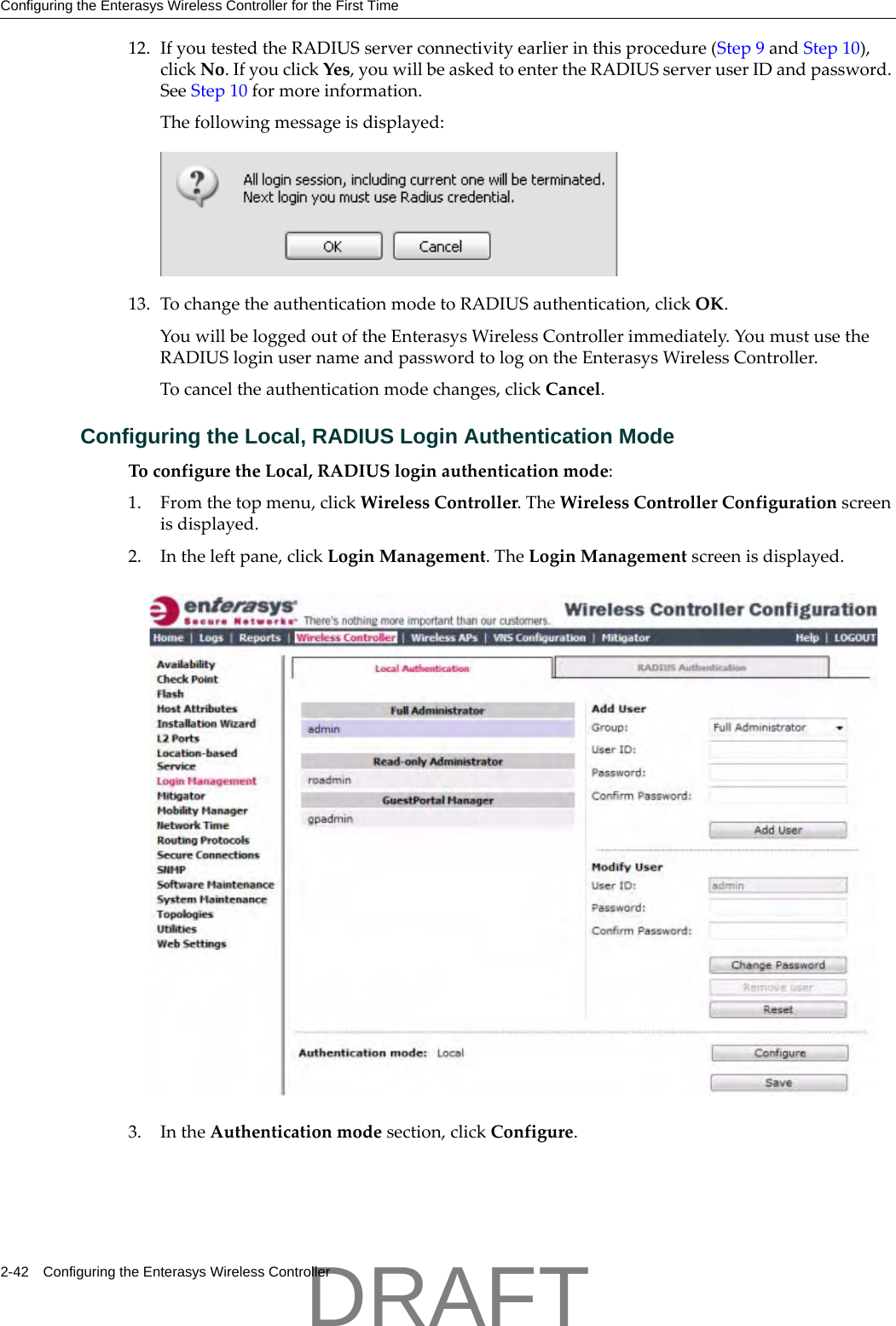
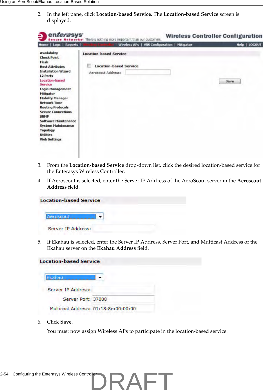
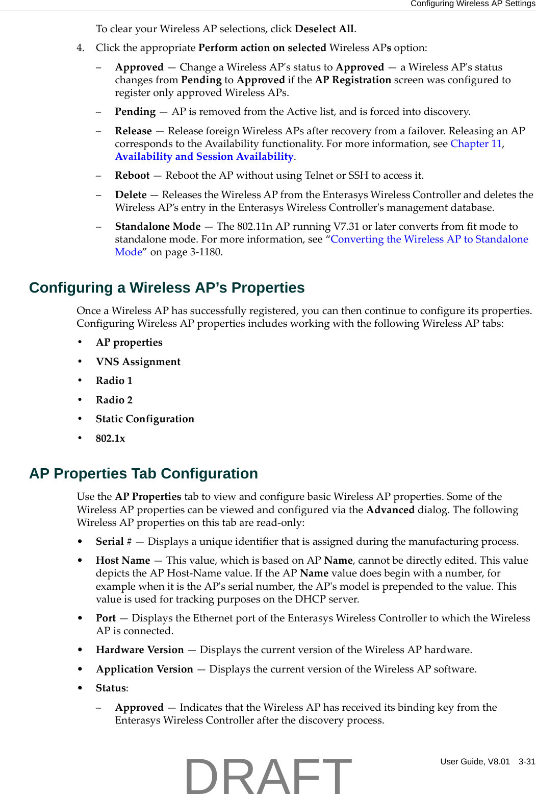
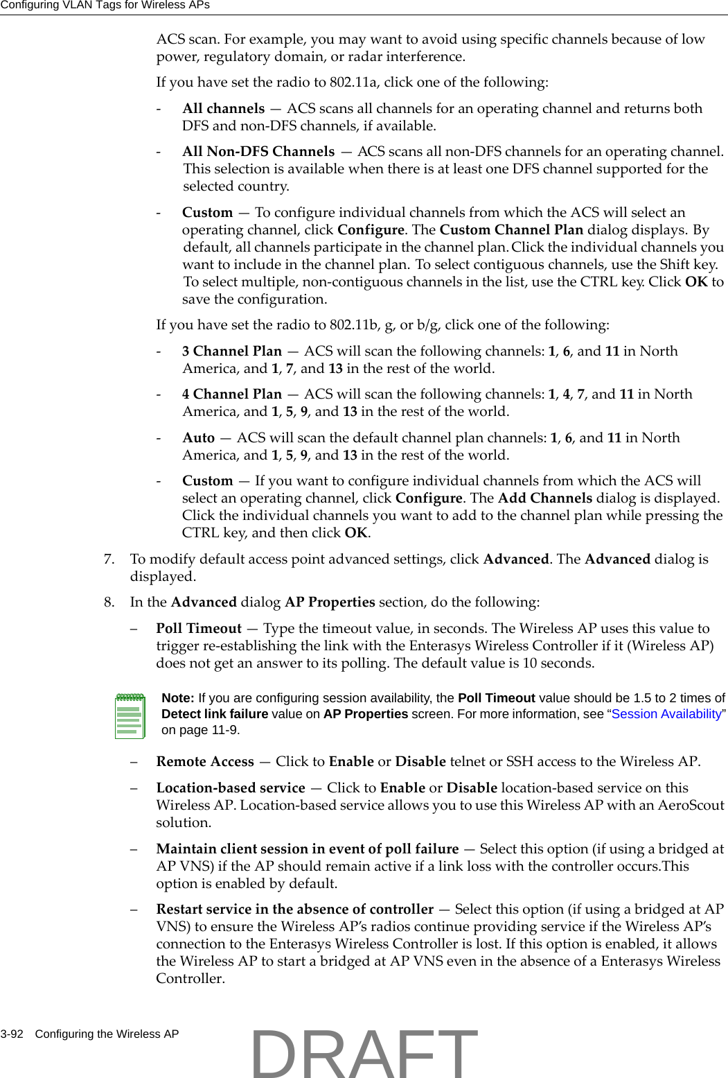
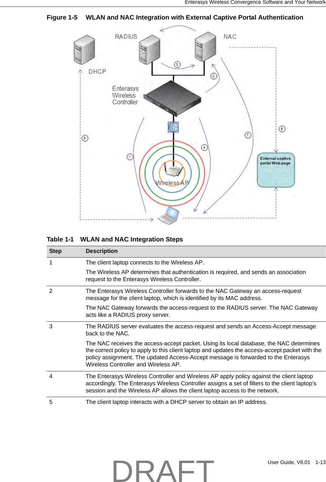
![Configuring the Enterasys Wireless Controller for the First TimeUser Guide, V8.01 2-27ThefollowingadditionalreportsdisplayOSPFinformationwhentheprotocolisinoperation:–OSPFNeighbor—DisplaysthecurrentneighborsforOSPF(routersthathaveinterfacestoacommonnetwork)–OSPFLinkstate—DisplaystheLinkStateAdvertisements(LSAs)receivedbythecurrentlyrunningOSPFprocess.TheLSAsdescribethelocalstateofarouterornetwork,includingthestateoftherouter’sinterfacesandadjacencies.2. Toupdatethedisplay,clickRefresh.Configuring Filtering at the Interface LevelTheEnterasysWirelesssolutionhasanumberofbuilt‐infiltersthatprotectthesystemfromunauthorizedtraffic.ThesefiltersarespecificonlytotheEnterasysWirelessController.Thesefiltersareappliedatthenetworkinterfacelevelandareautomaticallyinvoked.Bydefault,thesefiltersprovidestringent‐levelrulestoallowonlyaccesstothesystemʹsexternallyvisibleservices.Inadditiontothesebuilt‐infilters,theadministratorcandefinespecificexceptionfiltersattheinterface‐leveltocustomizenetworkaccess.ThesefiltersdependonTopologyModesandtheconfigurationofanL3interfaceforthetopology.ForBridgedatControllertopologies,exceptionfiltersaredefinedonlyifL3(IP)interfacesarespecified.ForPhysical,Routed,and3rdPartyAPtopologies,exceptionfilteringisalwaysconfiguredsincetheyallhaveanL3interfacepresence.Built-in Interface-based Exception FiltersOntheEnterasysWirelessController,variousinterface‐basedexceptionfiltersarebuiltinandinvokedautomatically.ThesefiltersprotecttheEnterasysWirelessControllerfromunauthorizedaccesstosystemmanagementfunctionsandservicesviatheinterfaces.Accesstosystemmanagementfunctionsisgrantediftheadministratorselectstheallowmanagementtrafficoptioninaspecifictopology.AllowmanagementtrafficispossibleonthetopologiesthathaveL3IPinterfacedefinitions.Forexample,ifmanagementtrafficisallowedonaphysicaltopology(esa0),onlyusersconnectedthroughESA0willbeabletogetaccesstothesystem.Usersconnectingonanyothertopology,suchasRoutedorBridgedLocallyatController,willnolongerbeabletotargetESA0togainmanagementaccesstothesystem.Toallowaccessforusersconnectedonsuchatopology,thegiventopologyconfigurationitselfmusthaveallowmanagementtrafficenabledanduserswillonlybeabletotargetthetopologyinterfacespecifically.OntheEnterasysWirelessController’sL3interfaces(associatedwitheitherphysical,Routed,orBridgedLocallyatControllertopologies),thebuilt‐inexceptionfilterprohibitsinvokingSSH,HTTPS,orSNMP.However,suchtrafficisallowed,bydefault,onthemanagementport.Ifmanagementtrafficisexplicitlyenabledforanyinterface,accessisimplicitlyextendedtothatinterfacethroughanyoftheotherinterfaces(VNS).Onlytrafficspecificallyallowedbytheinterface’sexceptionfilterisallowedtoreachtheEnterasysWirelessControlleritself.Allothertrafficisdropped.Exceptionfiltersaredynamicallyconfiguredandregeneratedwheneverthesystemʹsinterfacetopologychanges(forexample,achangeofIPaddressforanyinterface).Enablingmanagementtrafficonaninterfaceaddsadditionalrulestotheexceptionfilter,whichopensupthewell‐knownIP(TCP/UDP)ports,correspondingtotheHTTPS,SSH,andSNMPapplications.Theinterface‐basedbuilt‐inexceptionfilteringrules,inthecaseoftrafficfromwirelessusers,areapplicabletotraffictargeteddirectlyforthetopologyL3interface.Forexample,afilterspecifiedbyaPolicymaybegenericenoughtoallowtrafficaccesstotheEnterasysWirelessControllerʹsmanagement(forexample,AllowAll[*.*.*.*]).ExceptionfilterrulesareevaluatedaftertheuserʹsDRAFT](https://usermanual.wiki/Chantry-Networks/APXXX1.User-Manual/User-Guide-1621739-Page-67.png)