Chantry Networks APXXX1 HiPATH WIRELESS ACCESS POINT (AP) User Manual USERS MANUAL 1
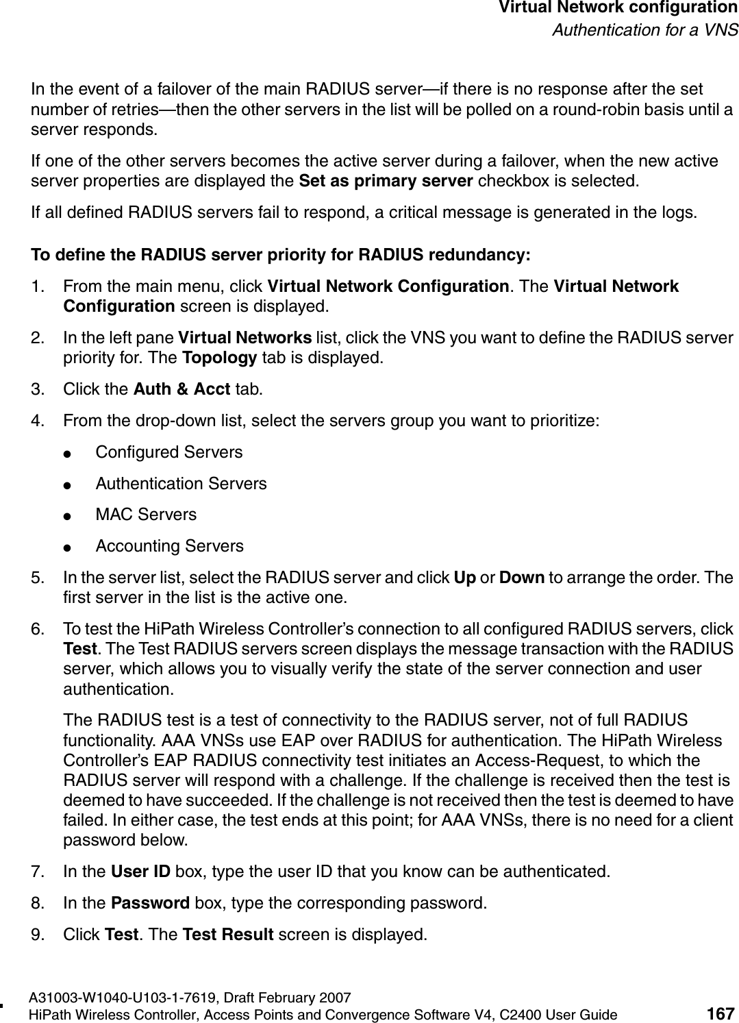
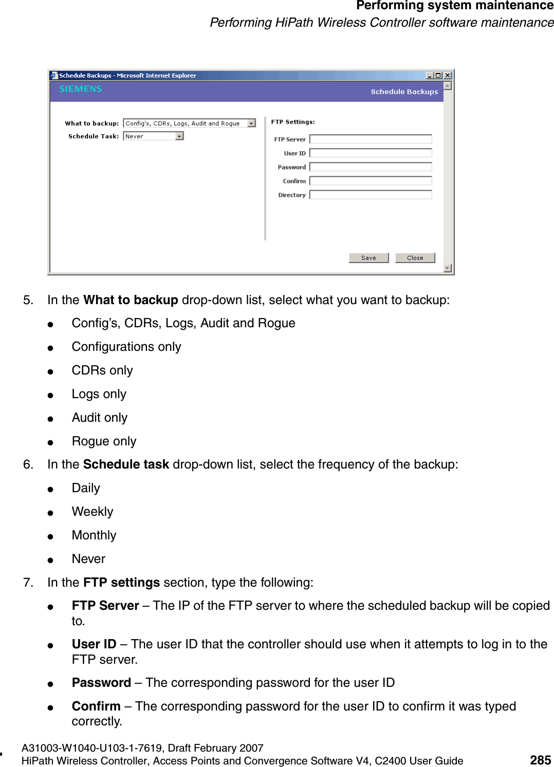
Chantry Networks Inc. (a Siemens Company) HiPATH WIRELESS ACCESS POINT (AP) USERS MANUAL 1
UserManual.wiki
>
Chantry Networks
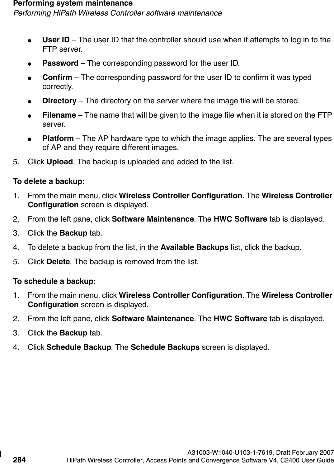
>
APXXX1 User Manual
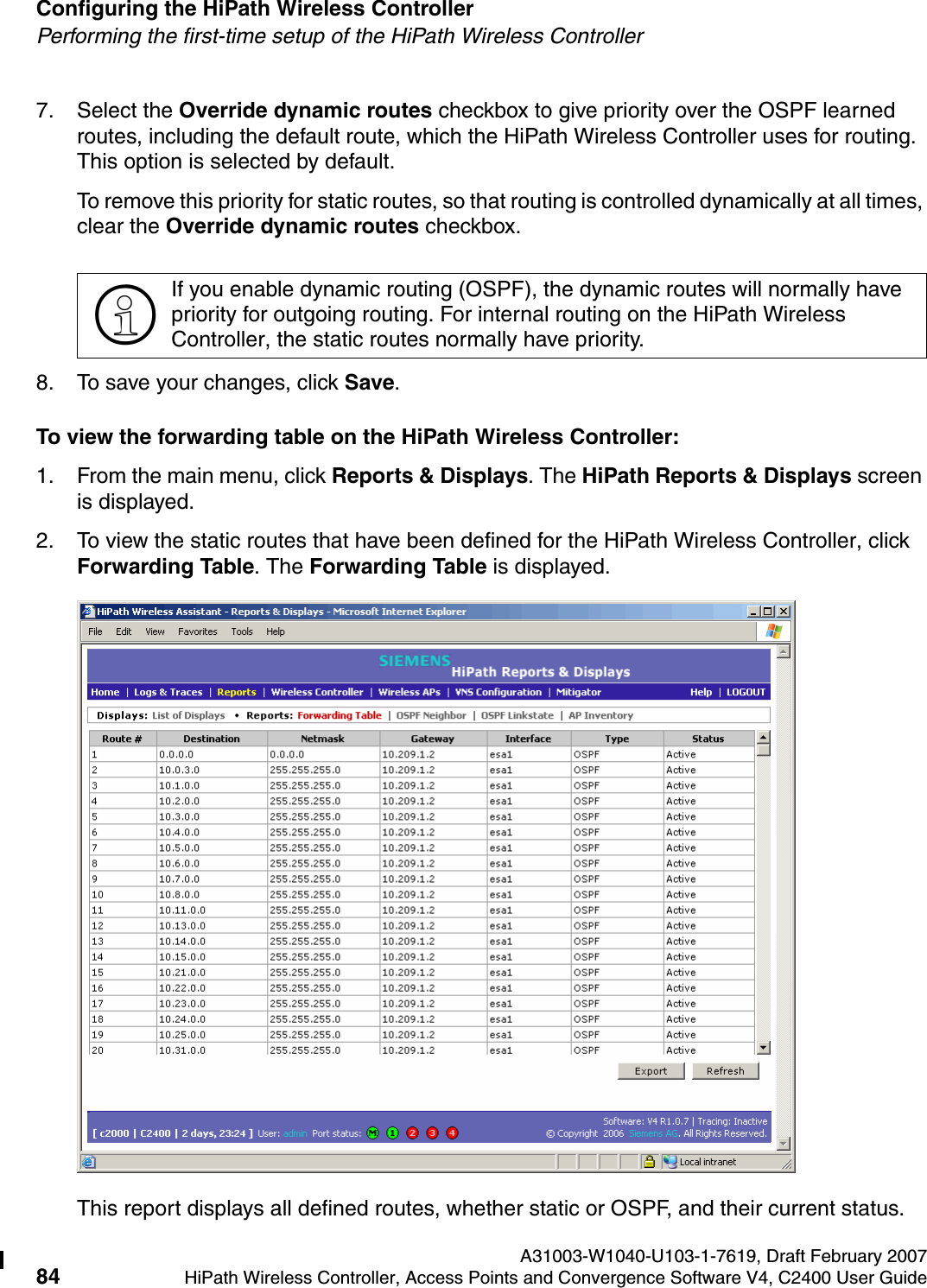
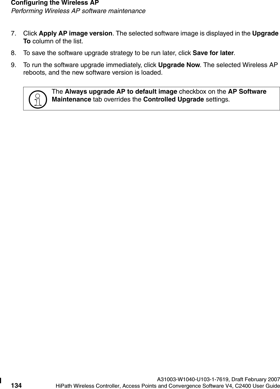
>
USERS MANUAL 1
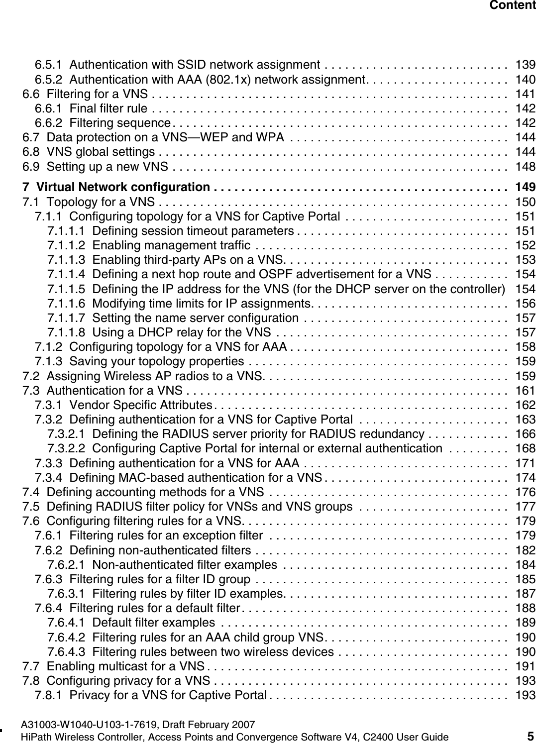
Contents
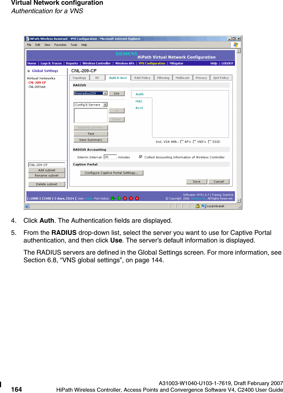
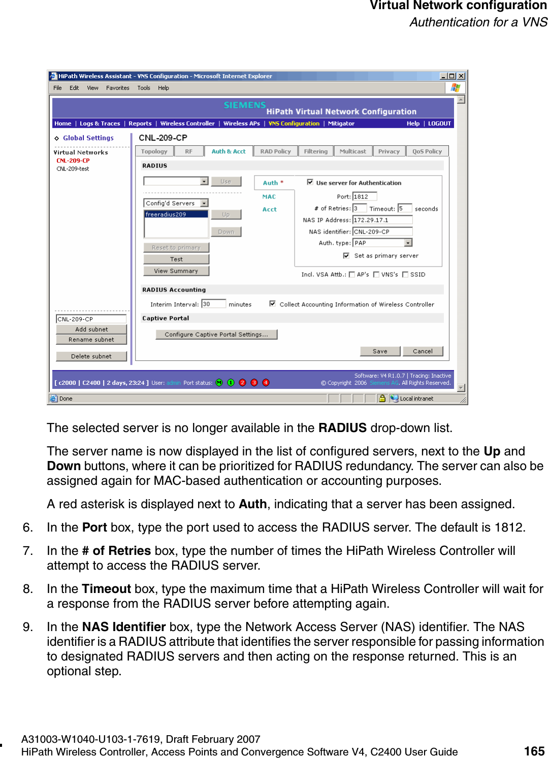
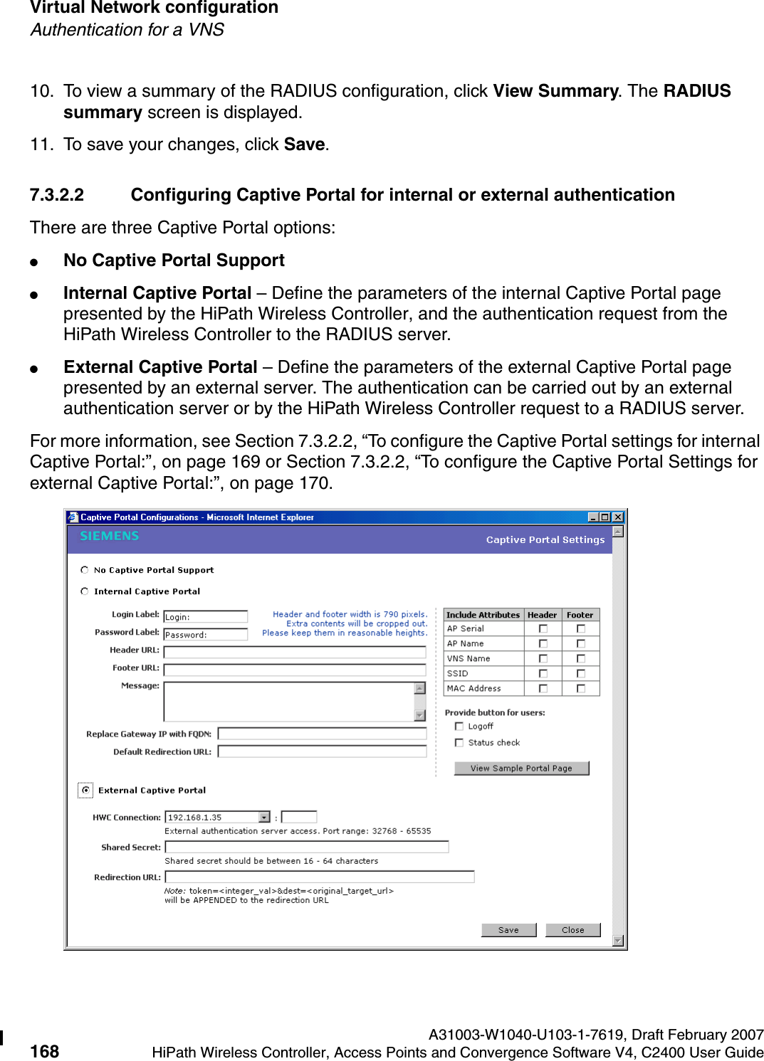
1.
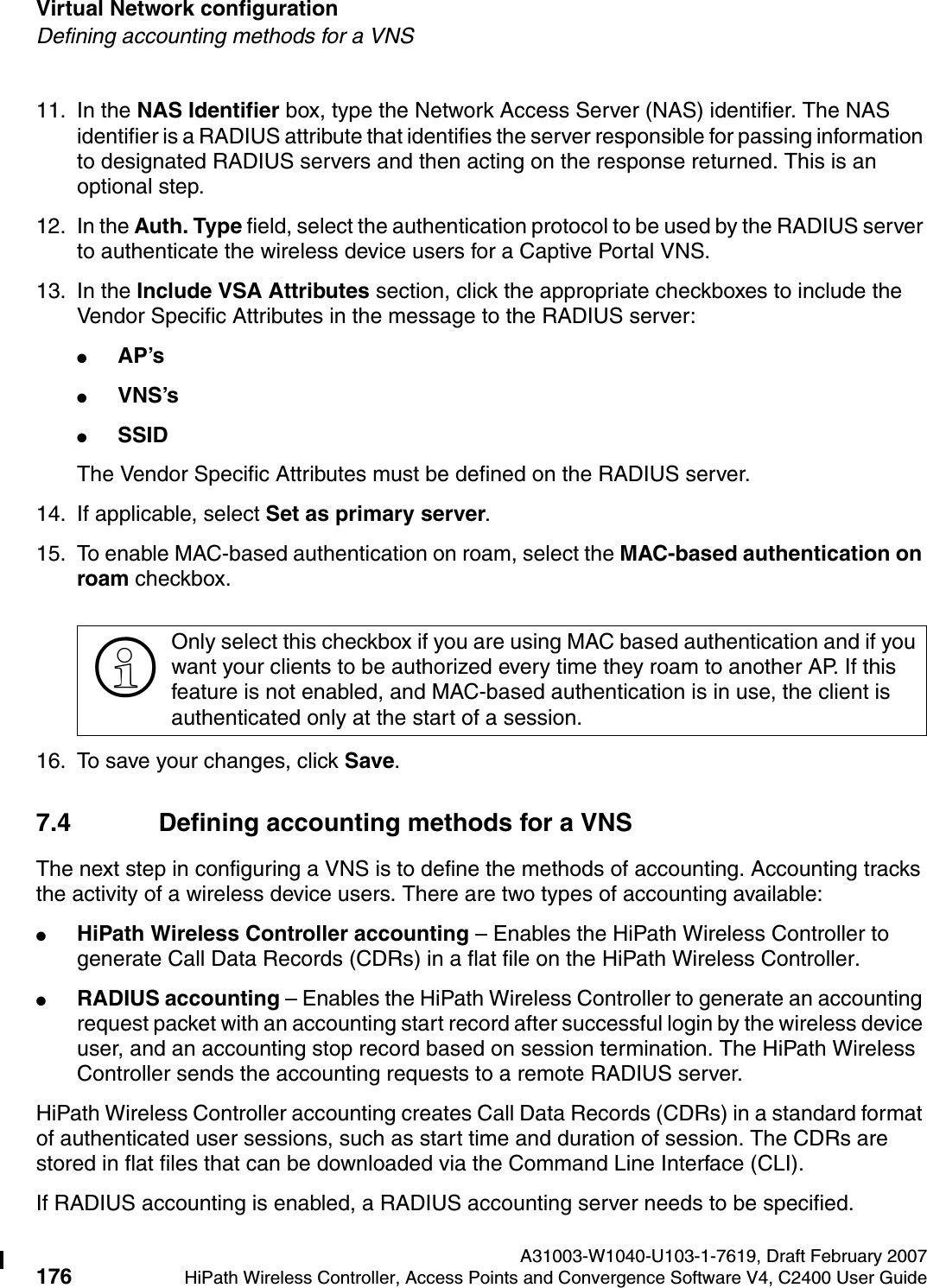
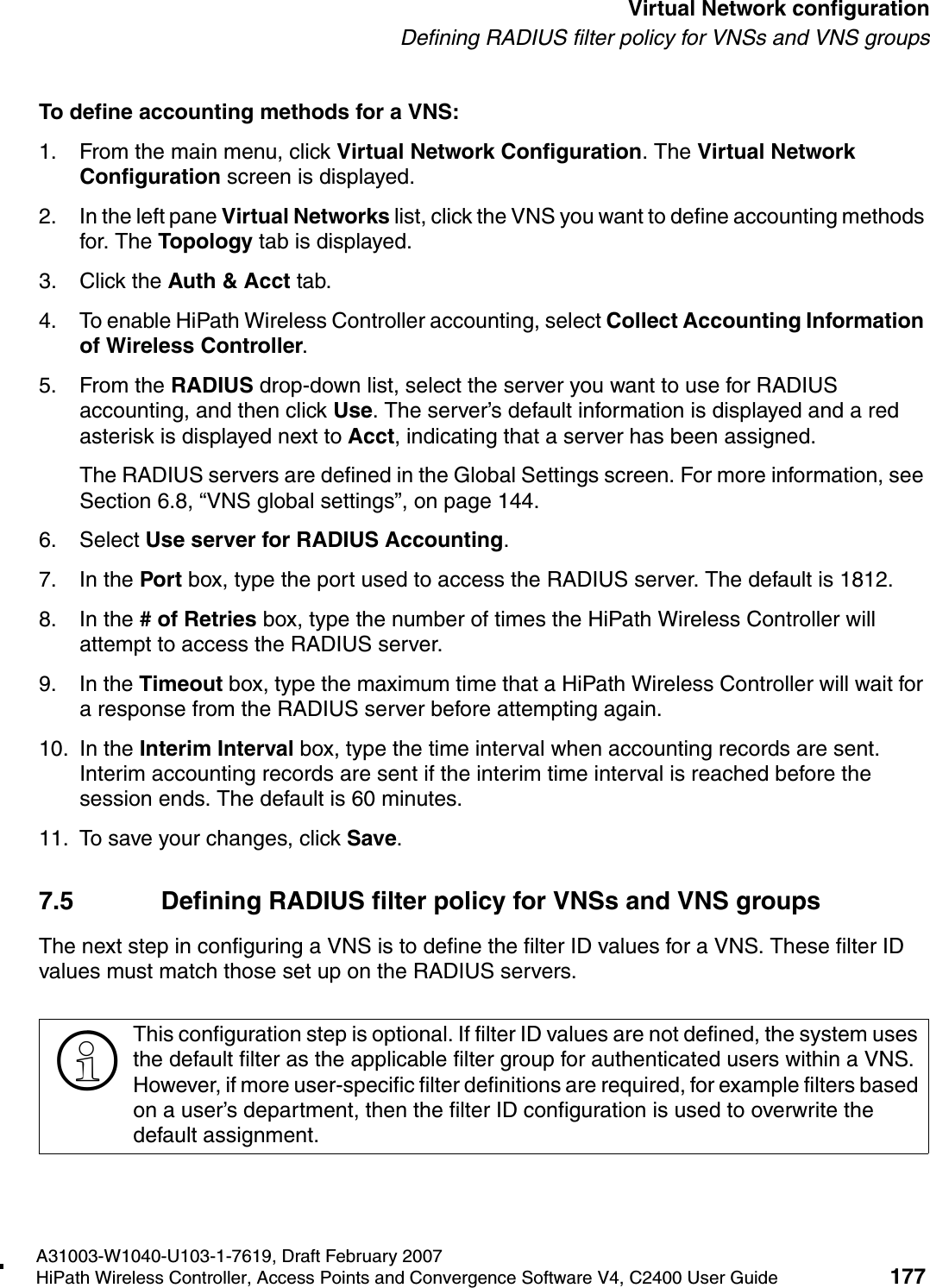
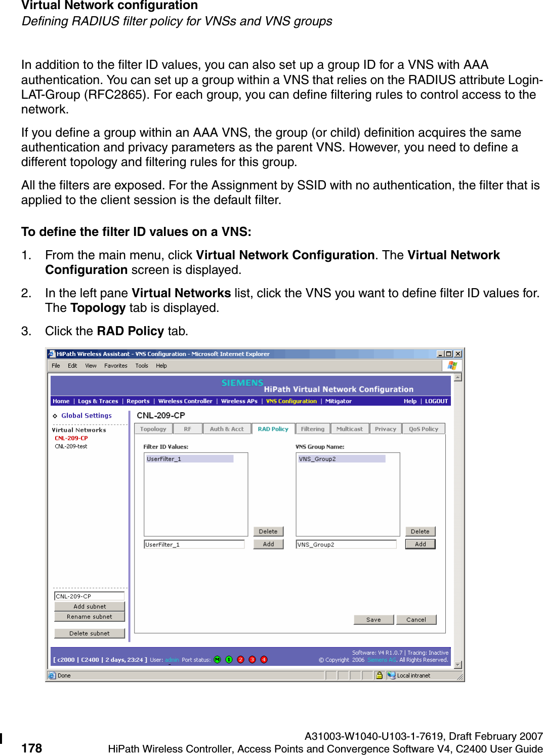
USERS MANUAL
2.
USERS MANUAL 1
3.
USERS MANUAL 2
4.
Users Manual
5.
users manual
6.
User Manual
USERS MANUAL 1
Navigation menu
Upload a User Manual
Namespaces
Wiki Guide
HTML
PDF
Info
Views
User Manual
Discussion / Help
Navigation
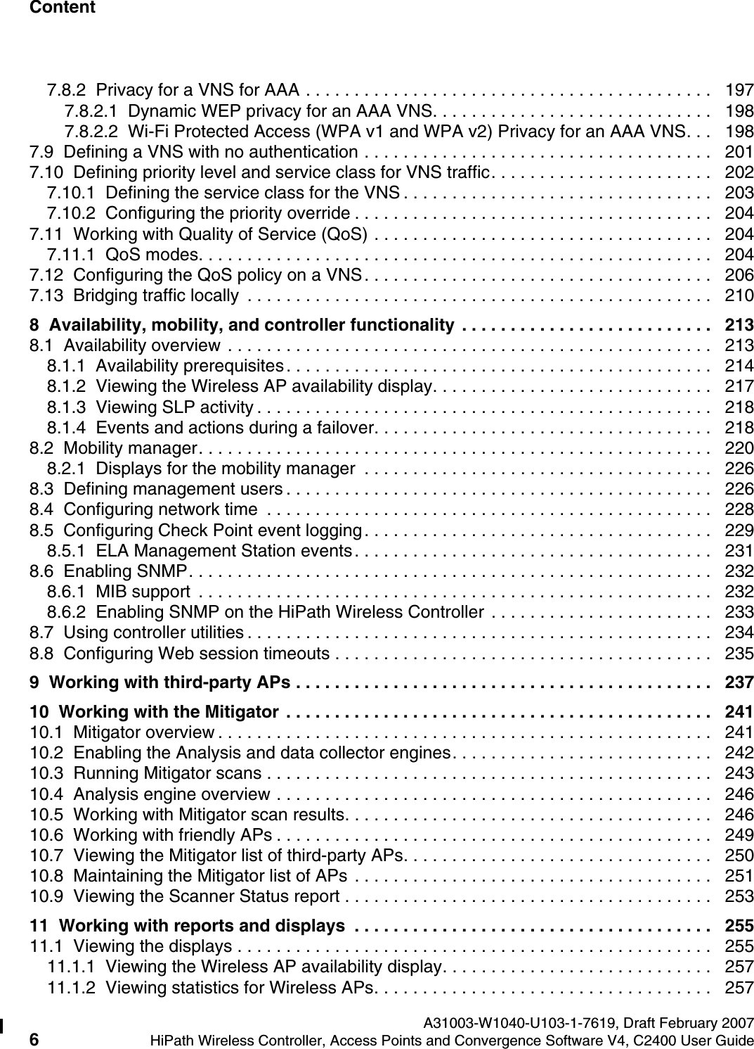

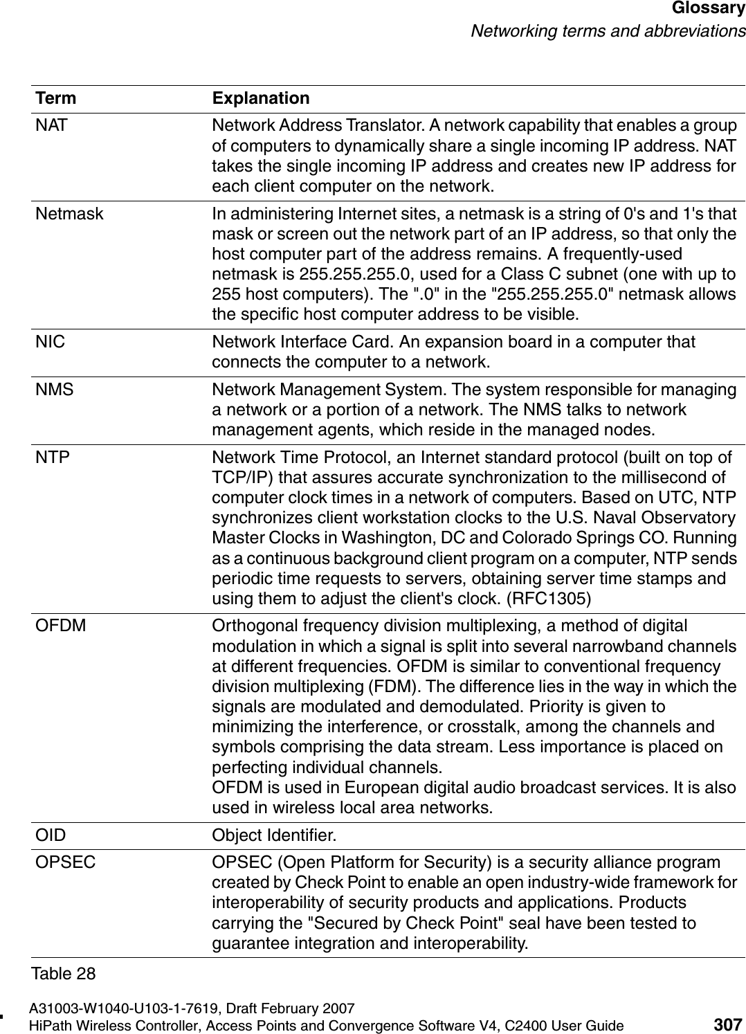
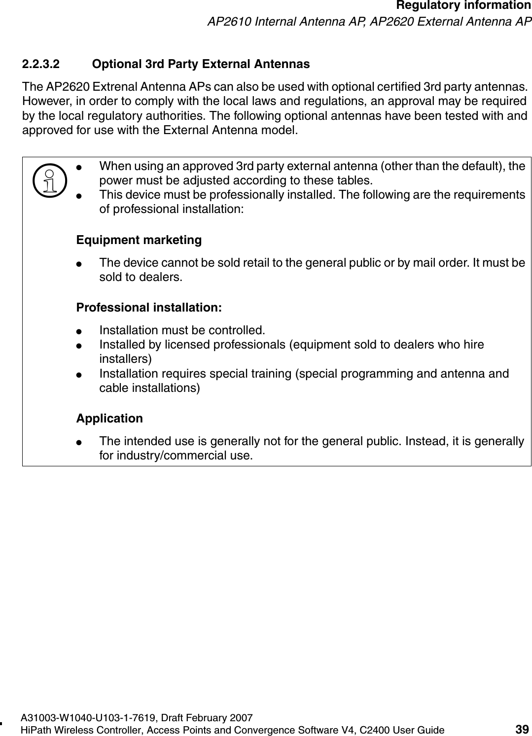
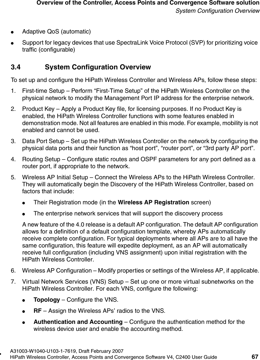
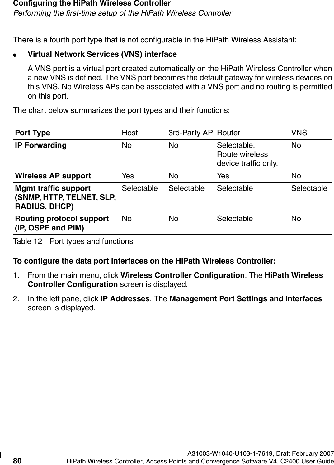
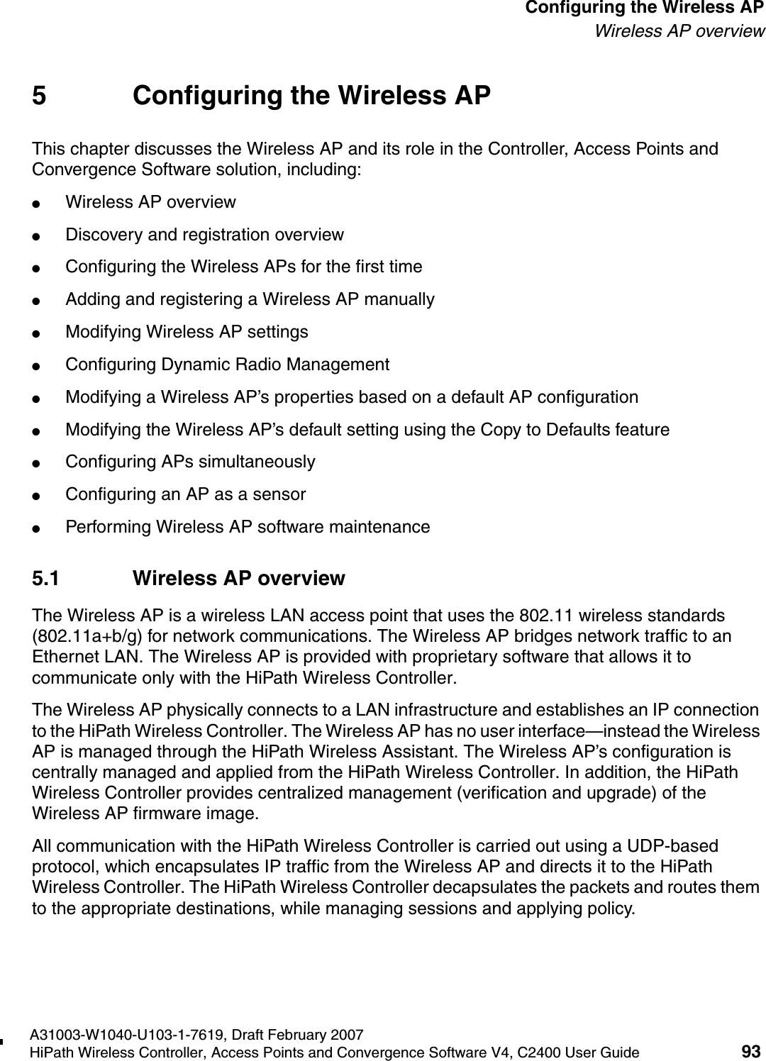
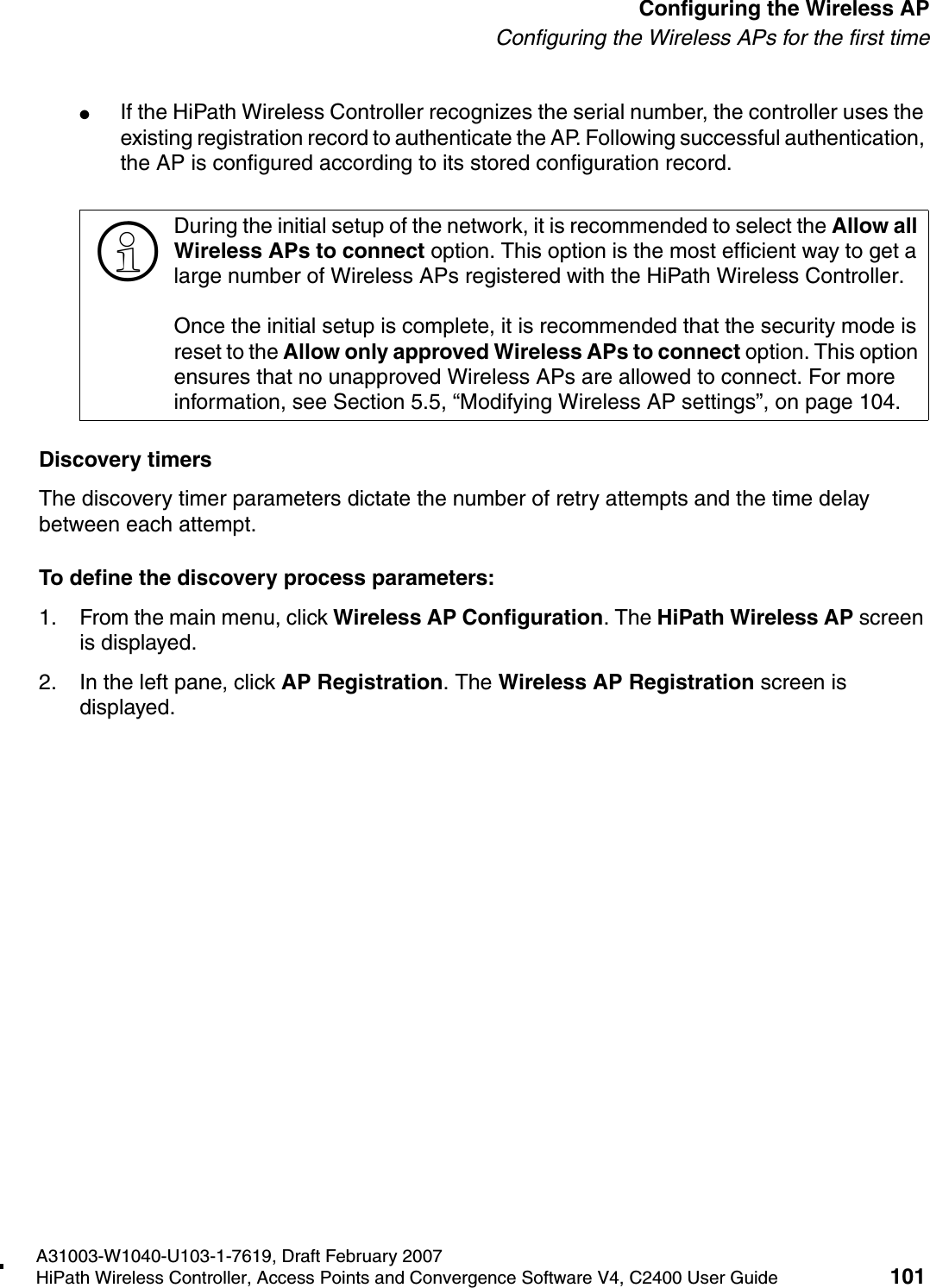
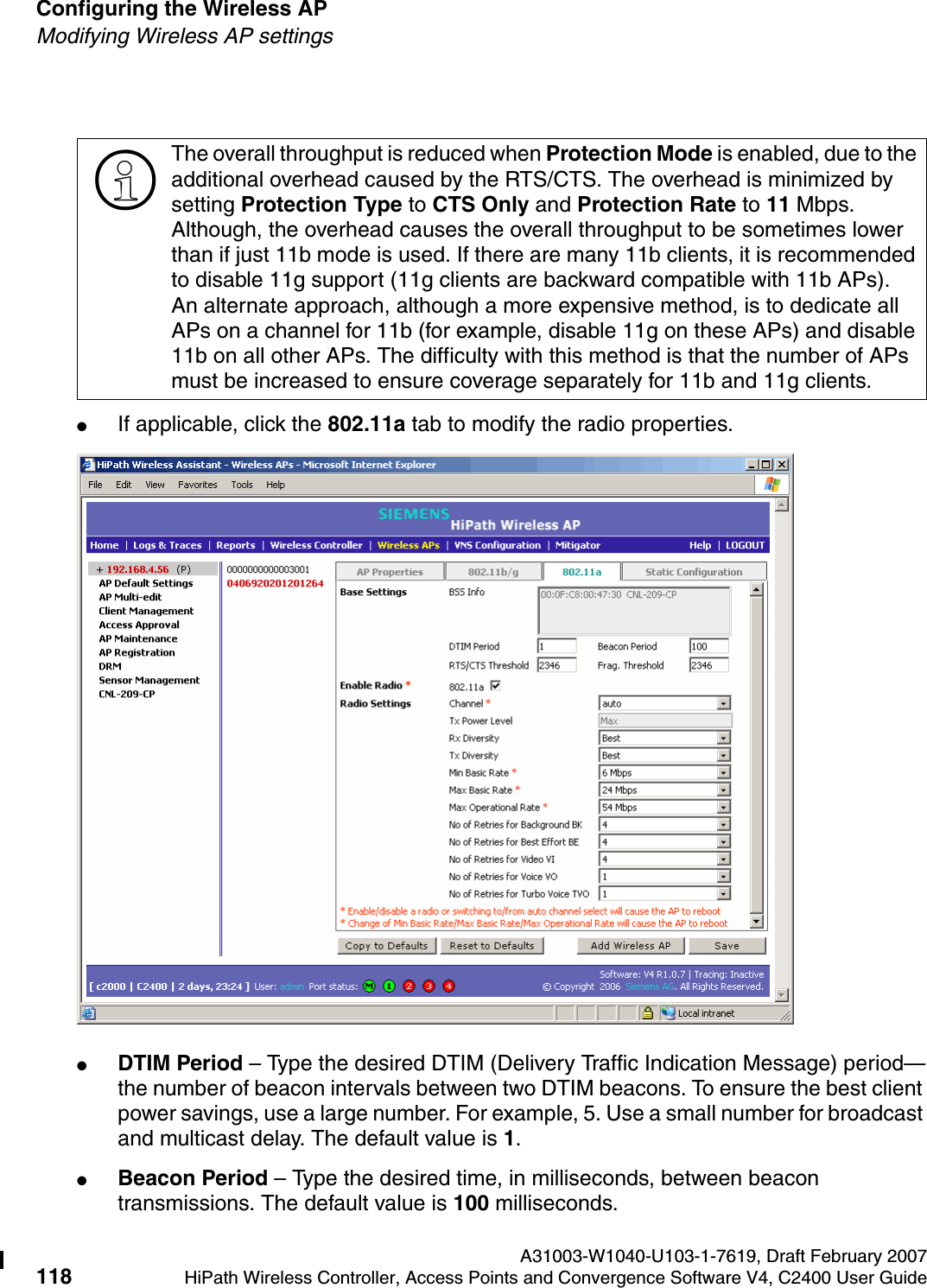
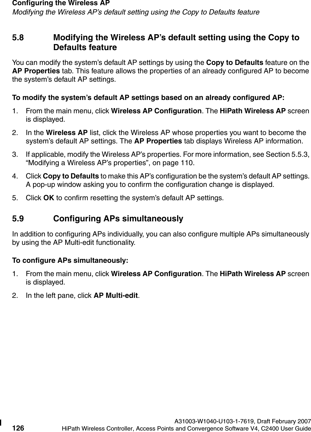
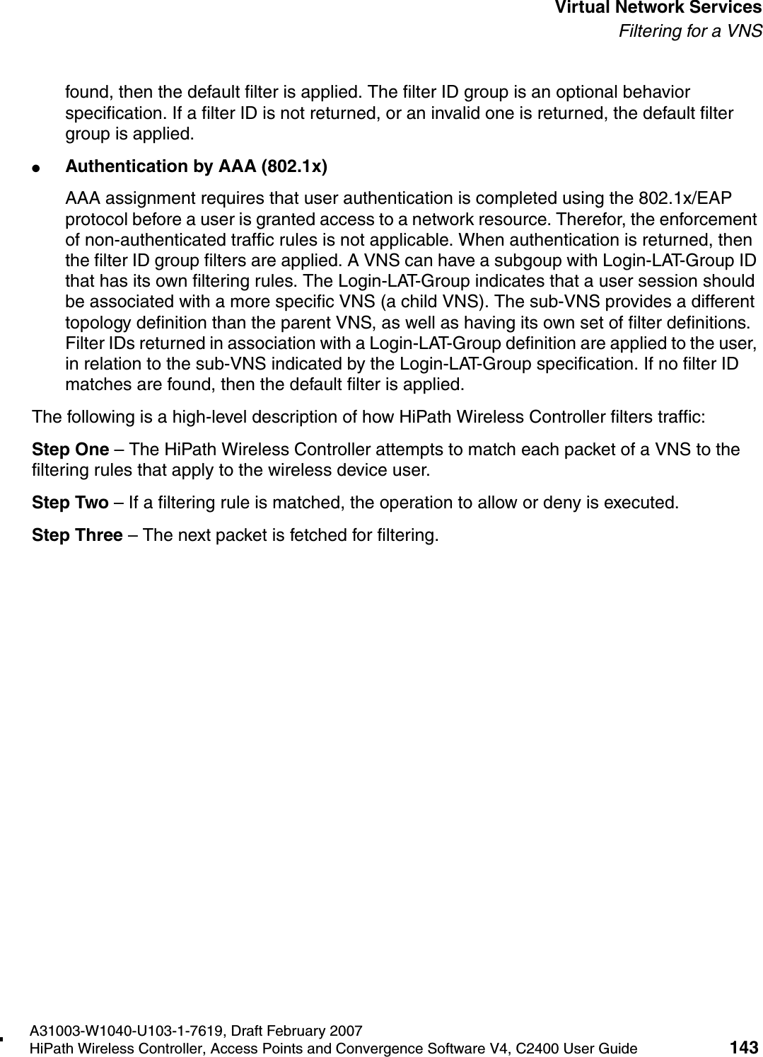
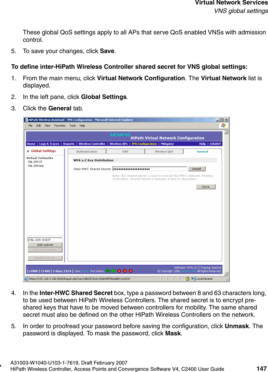
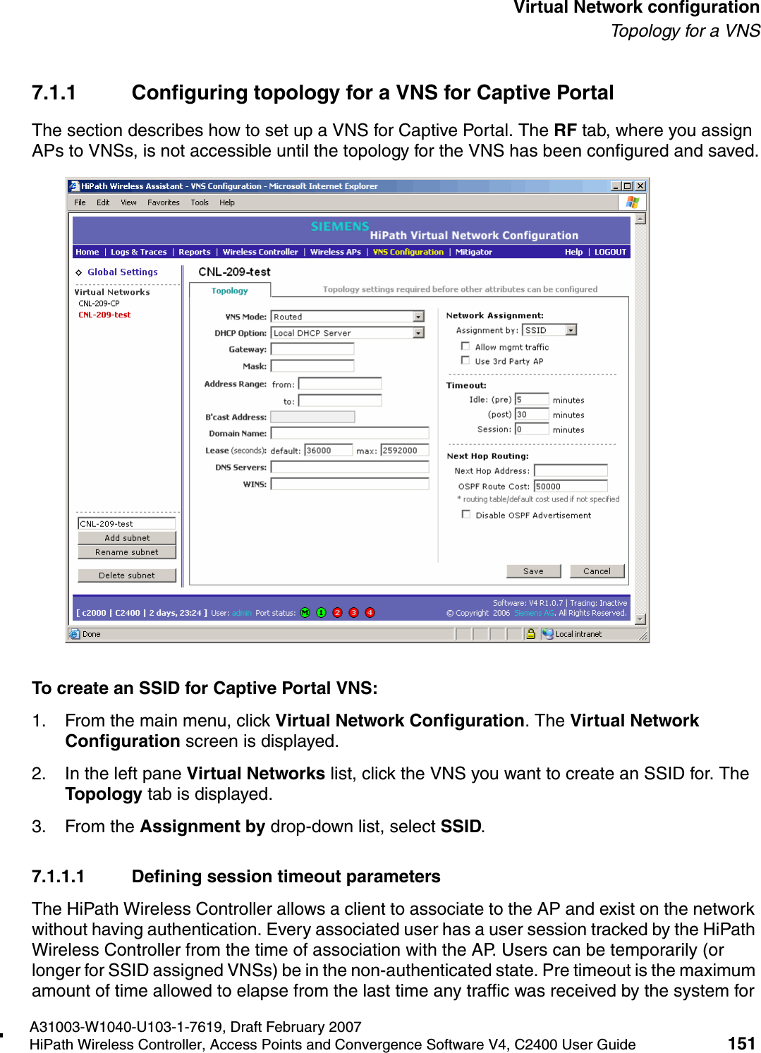
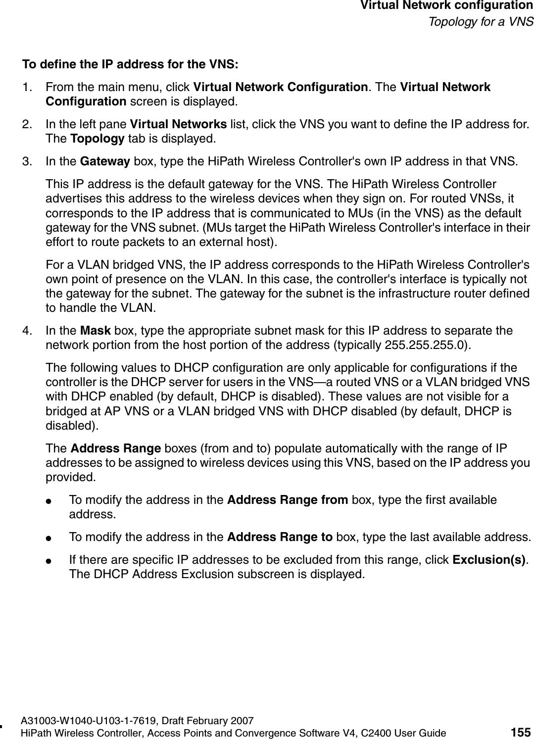
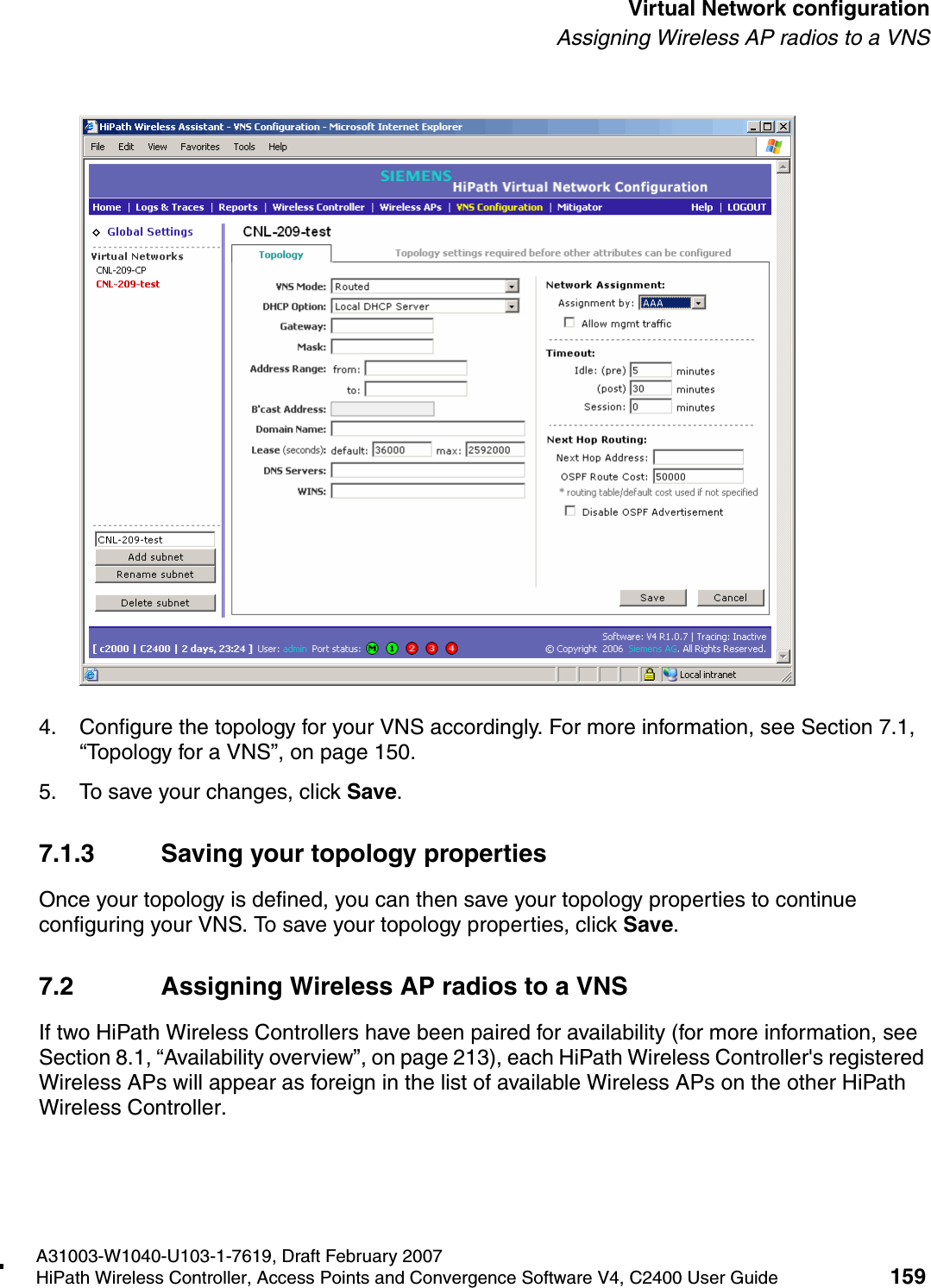
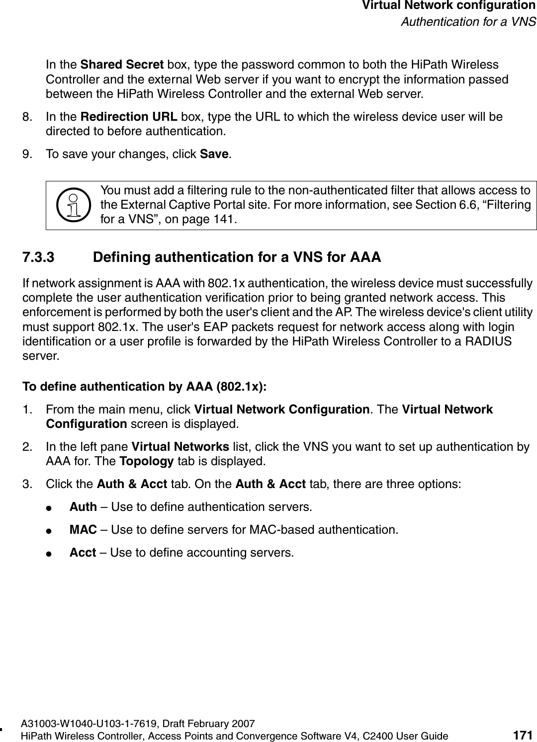
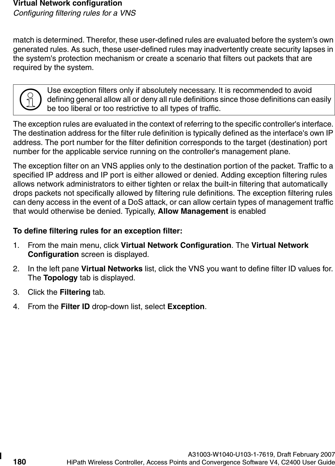
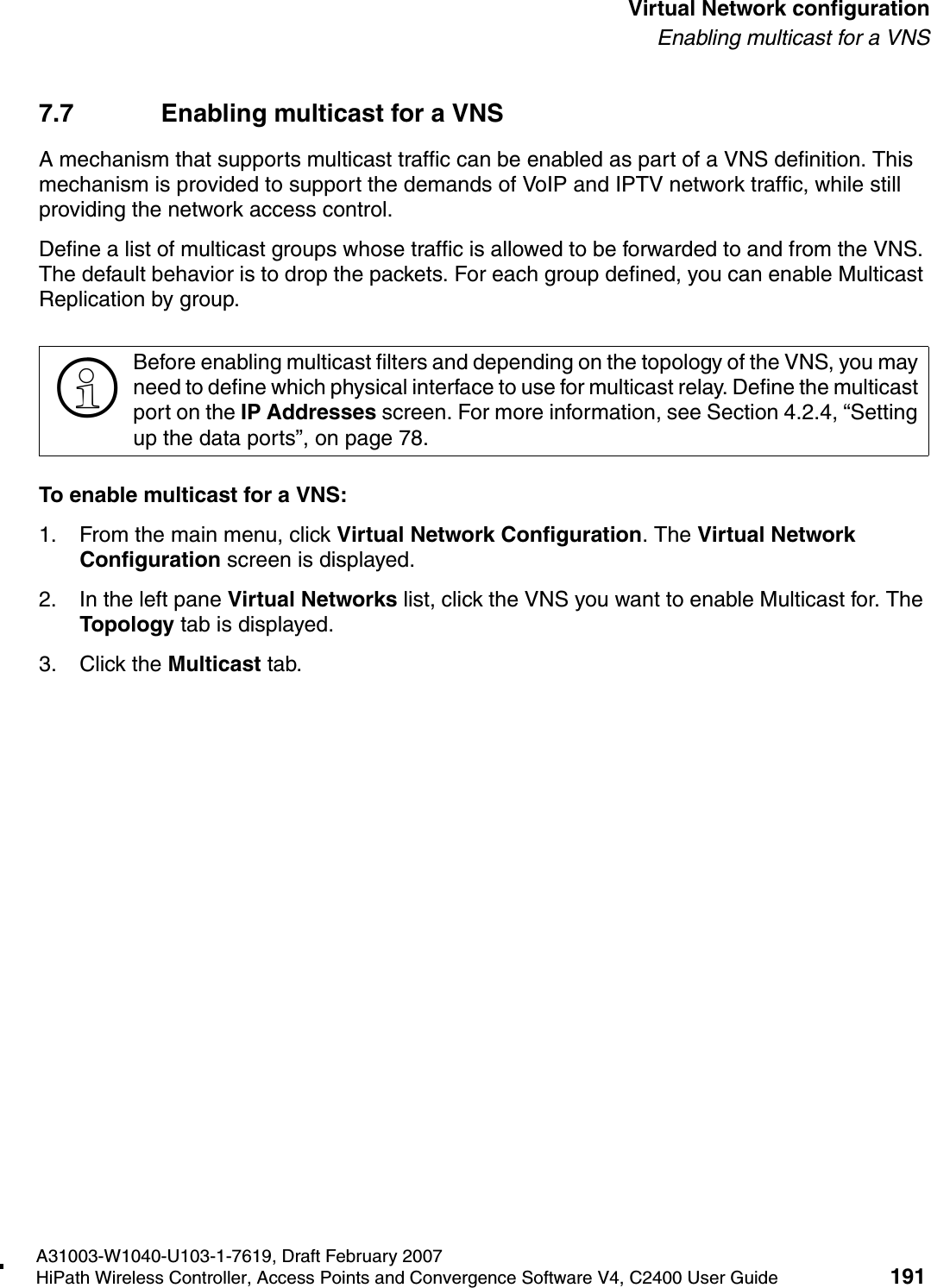
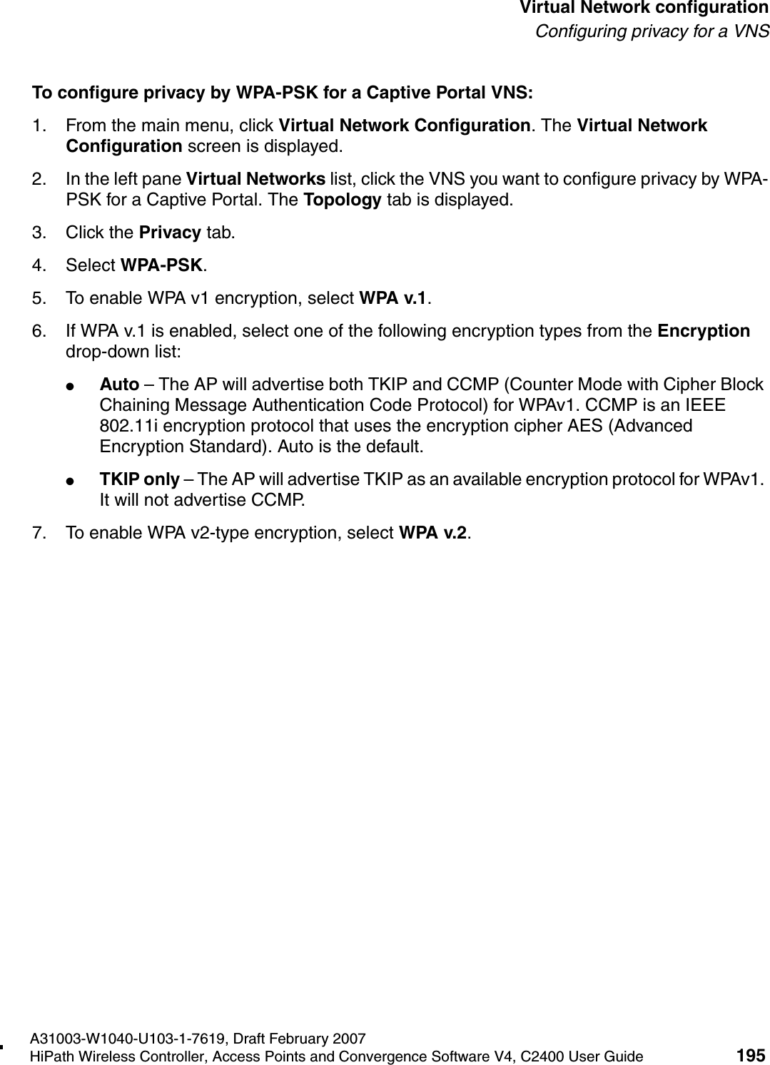
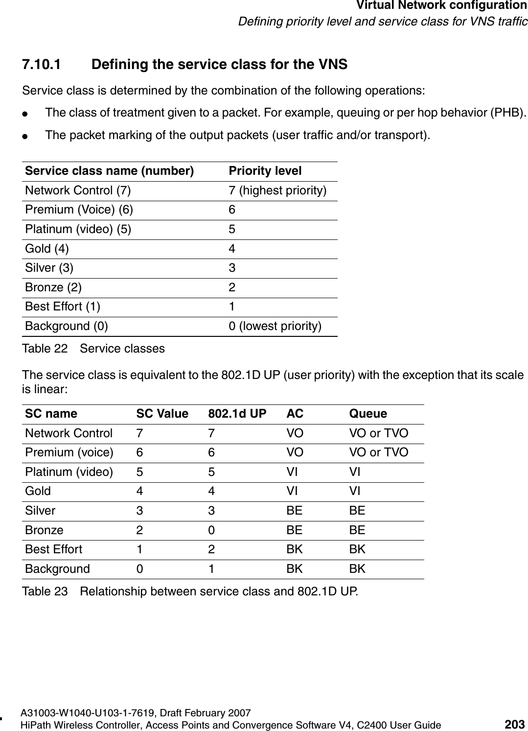
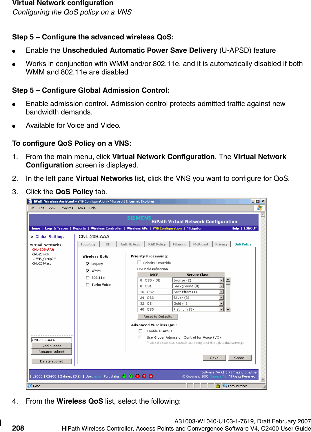
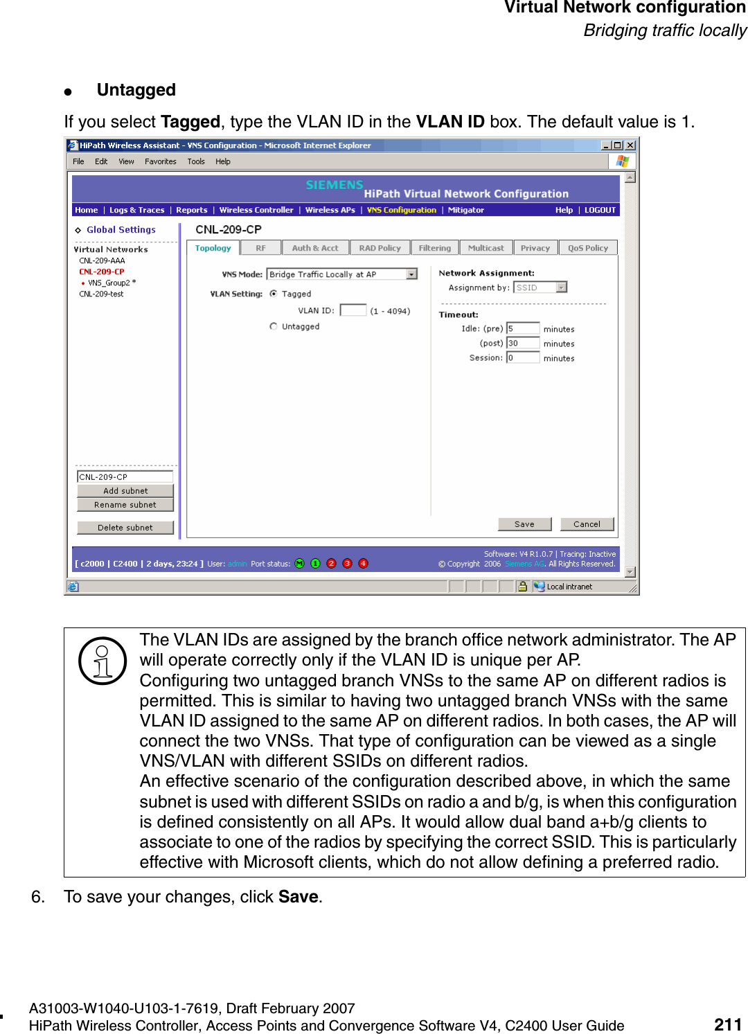
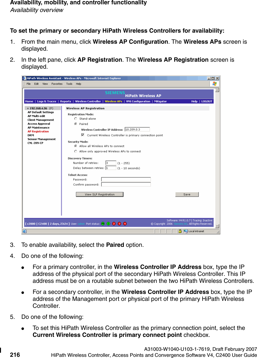
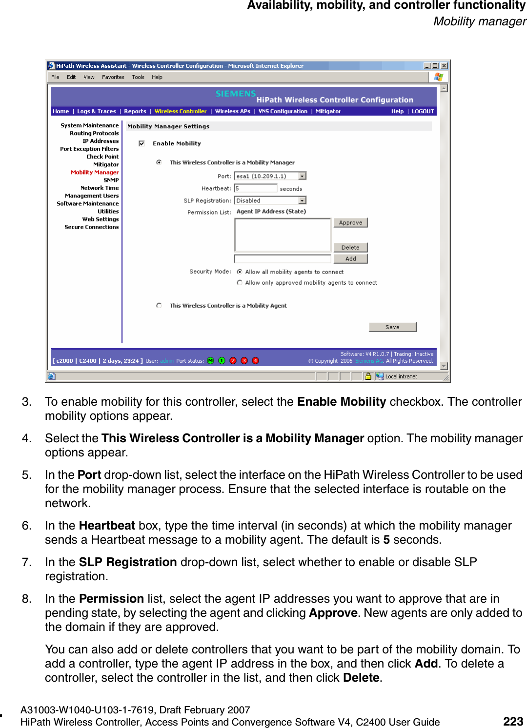
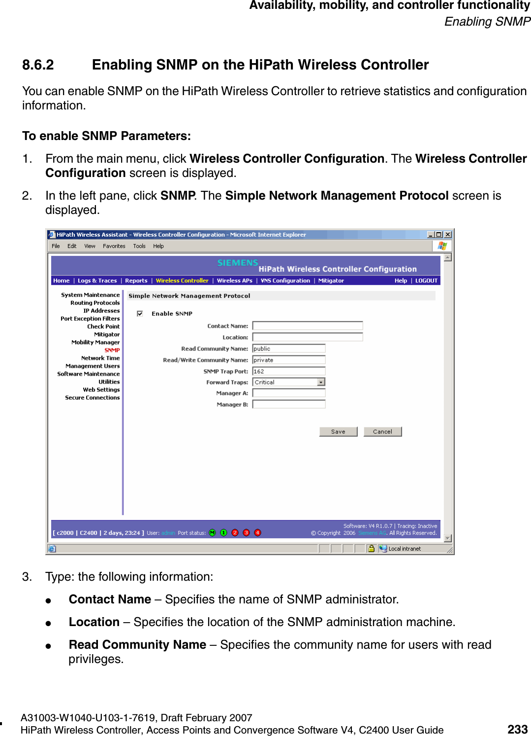
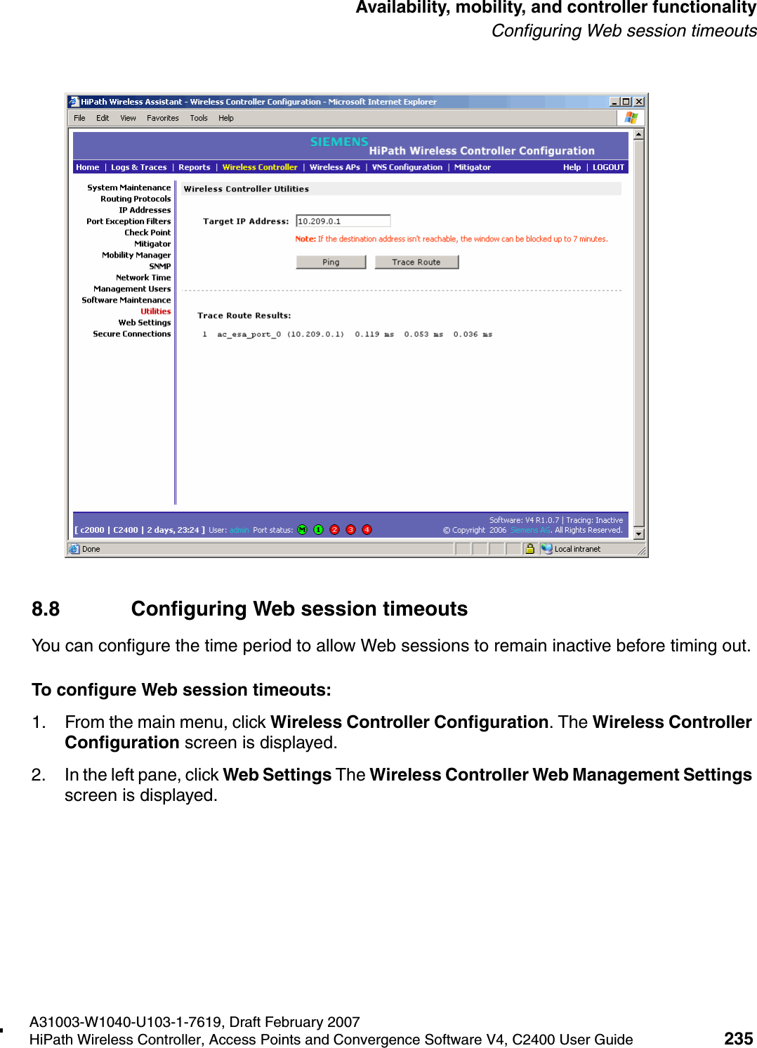
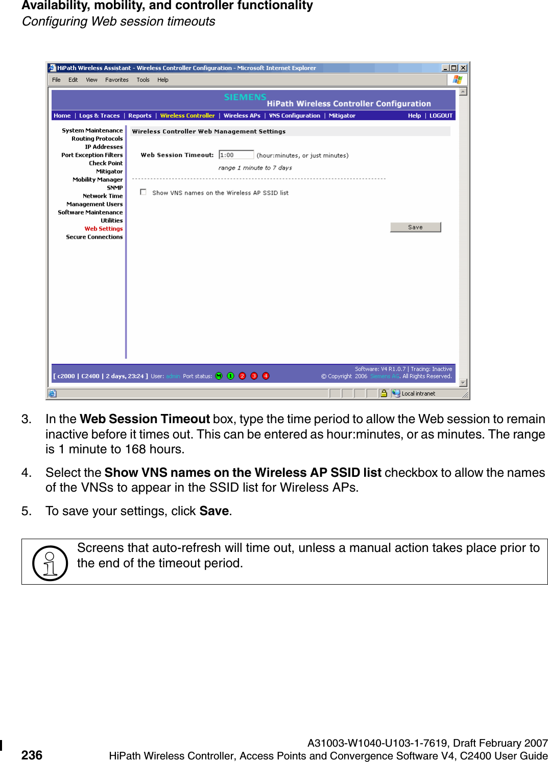
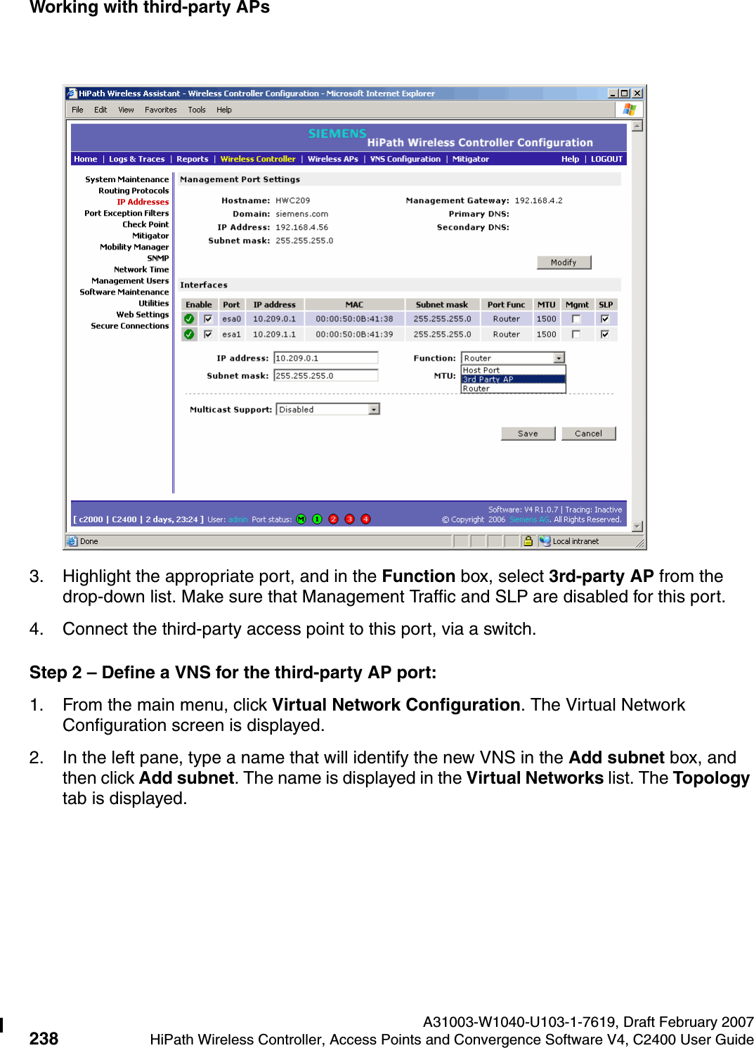
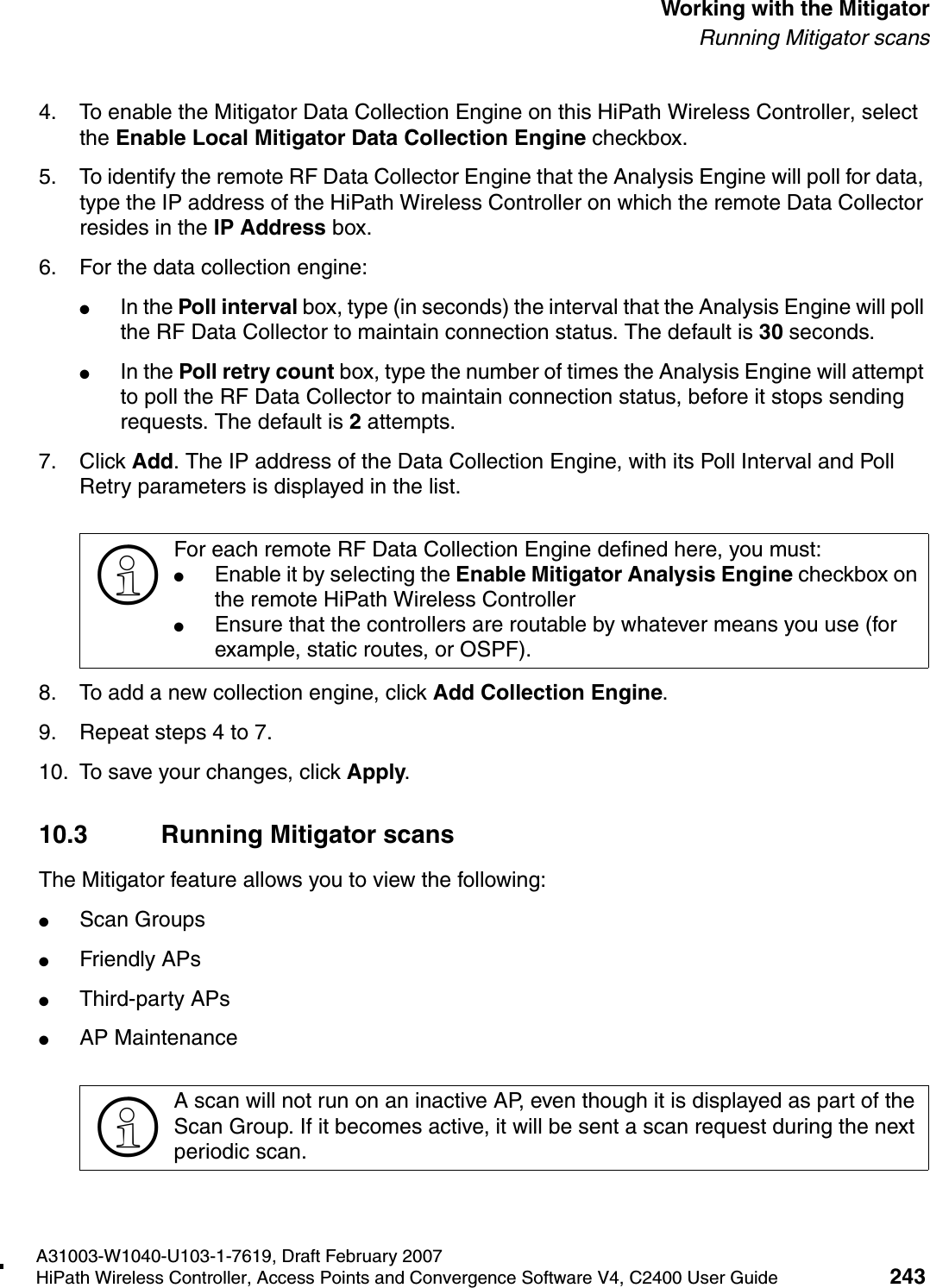
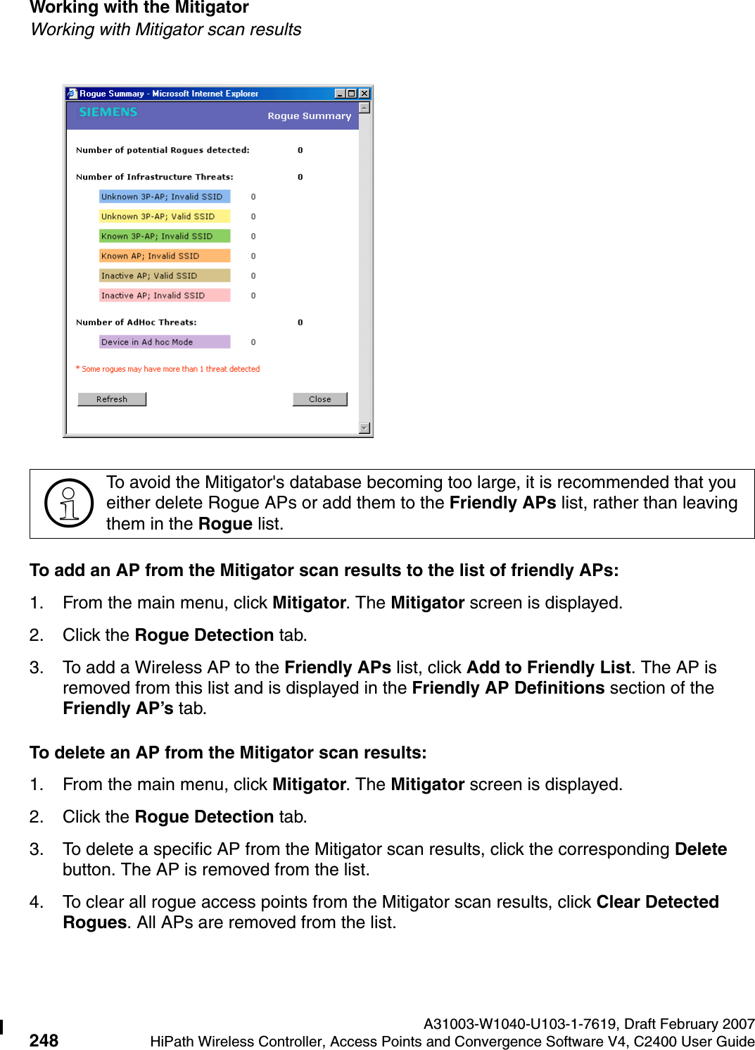
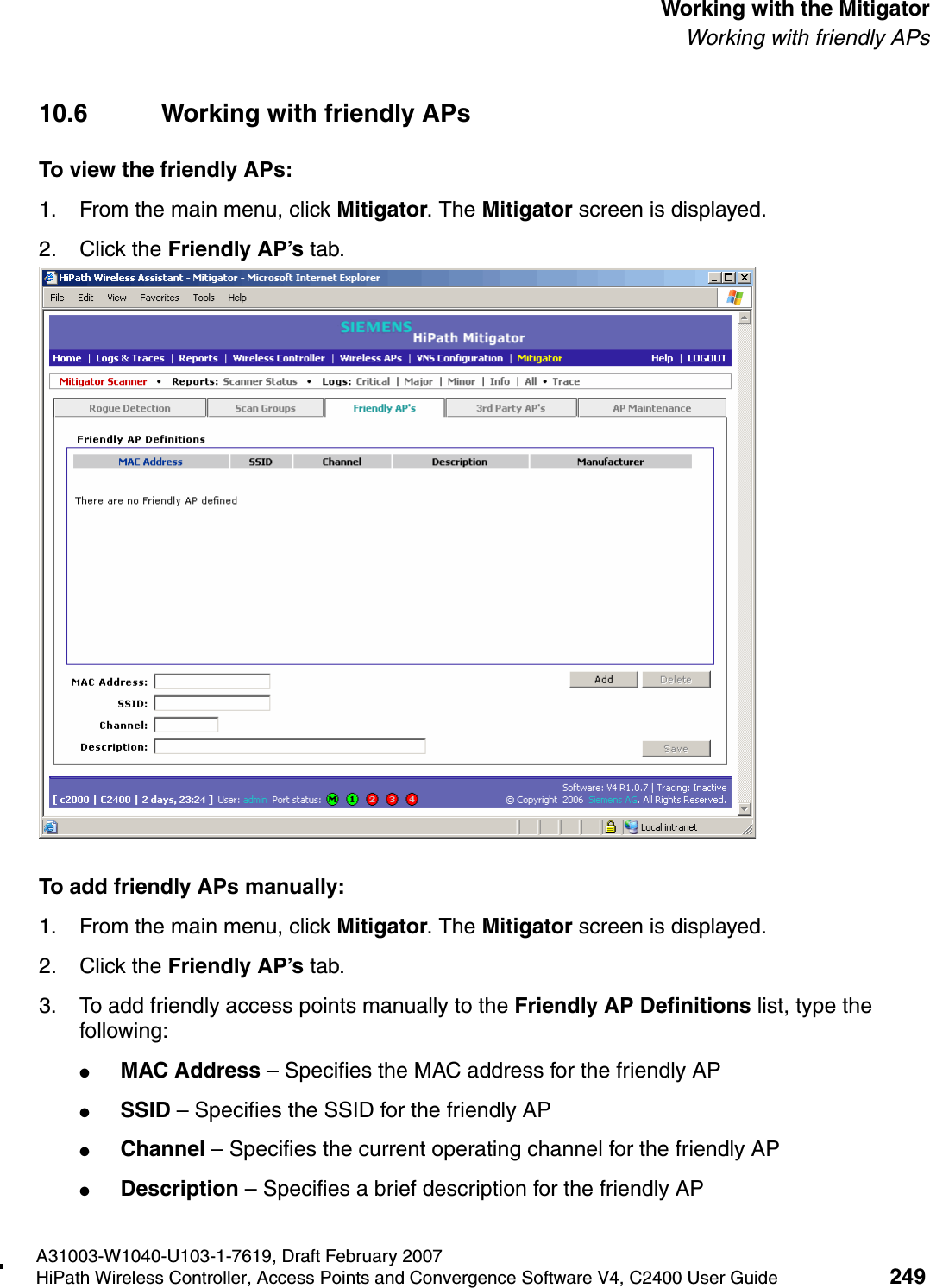
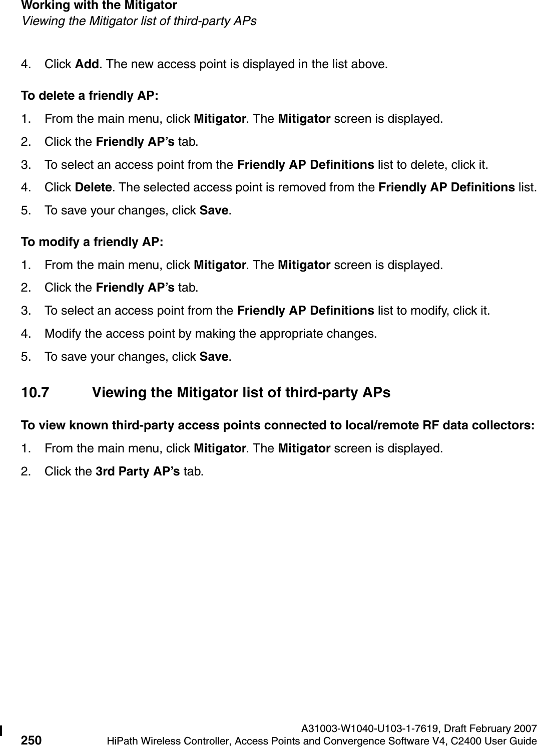
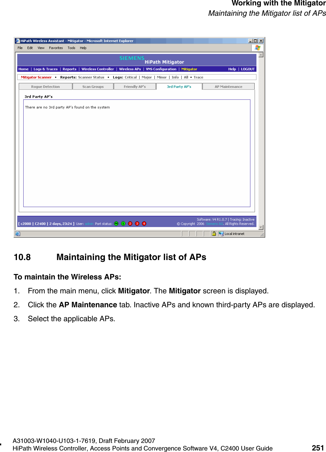
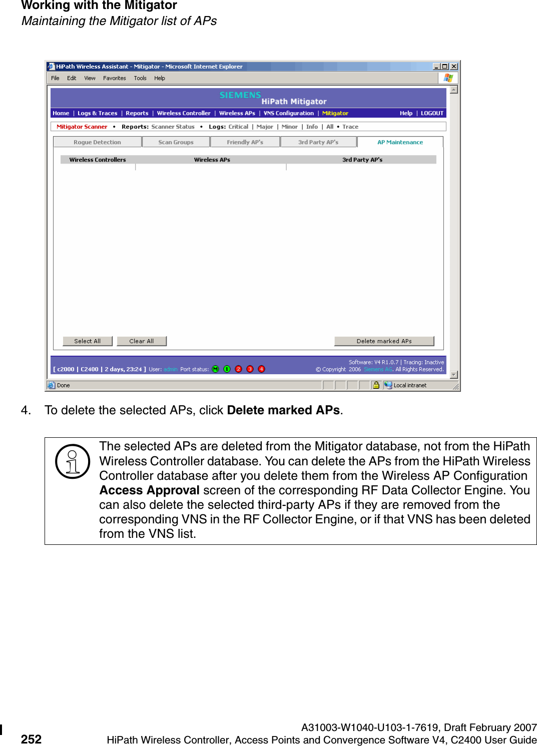
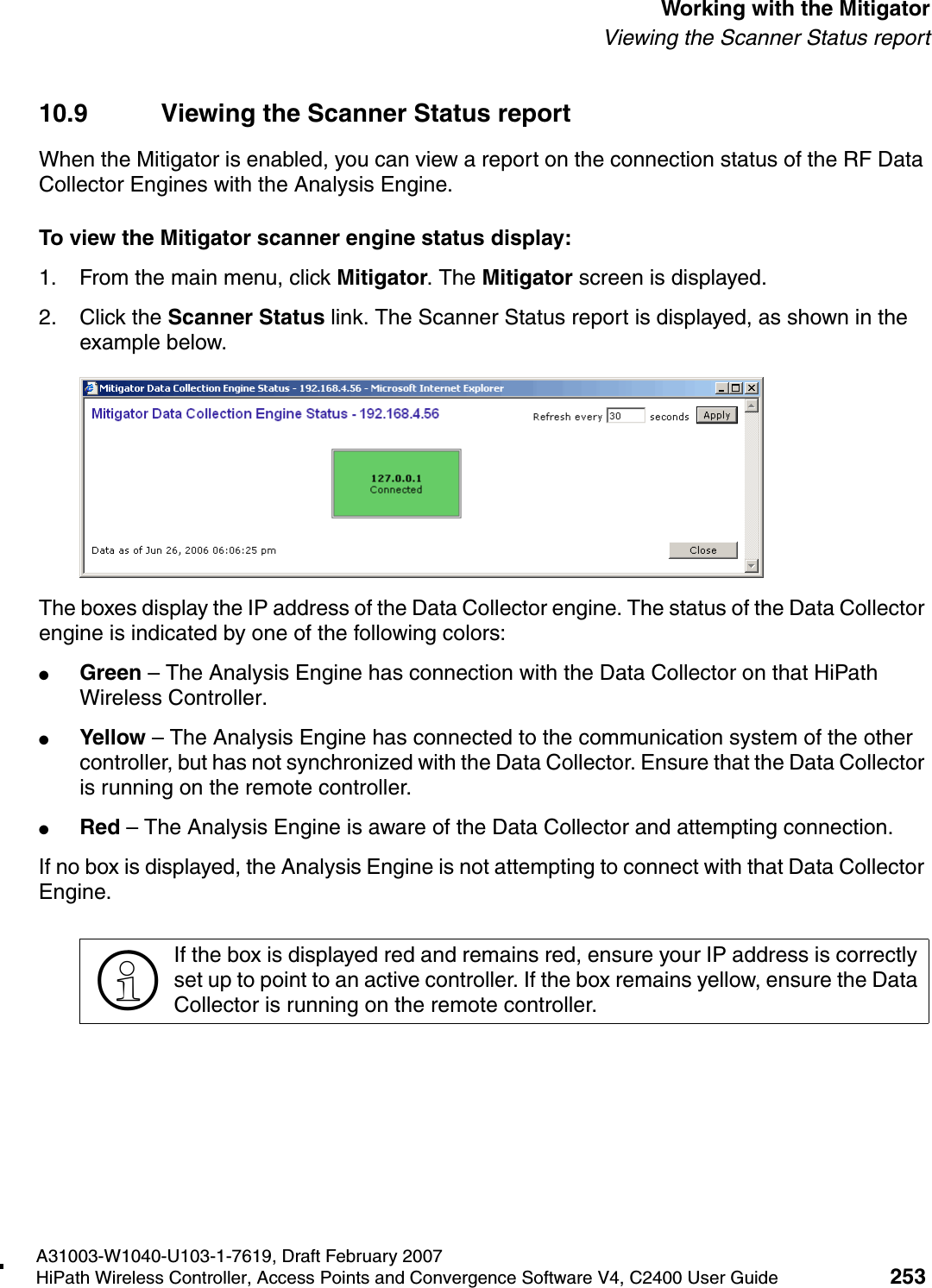
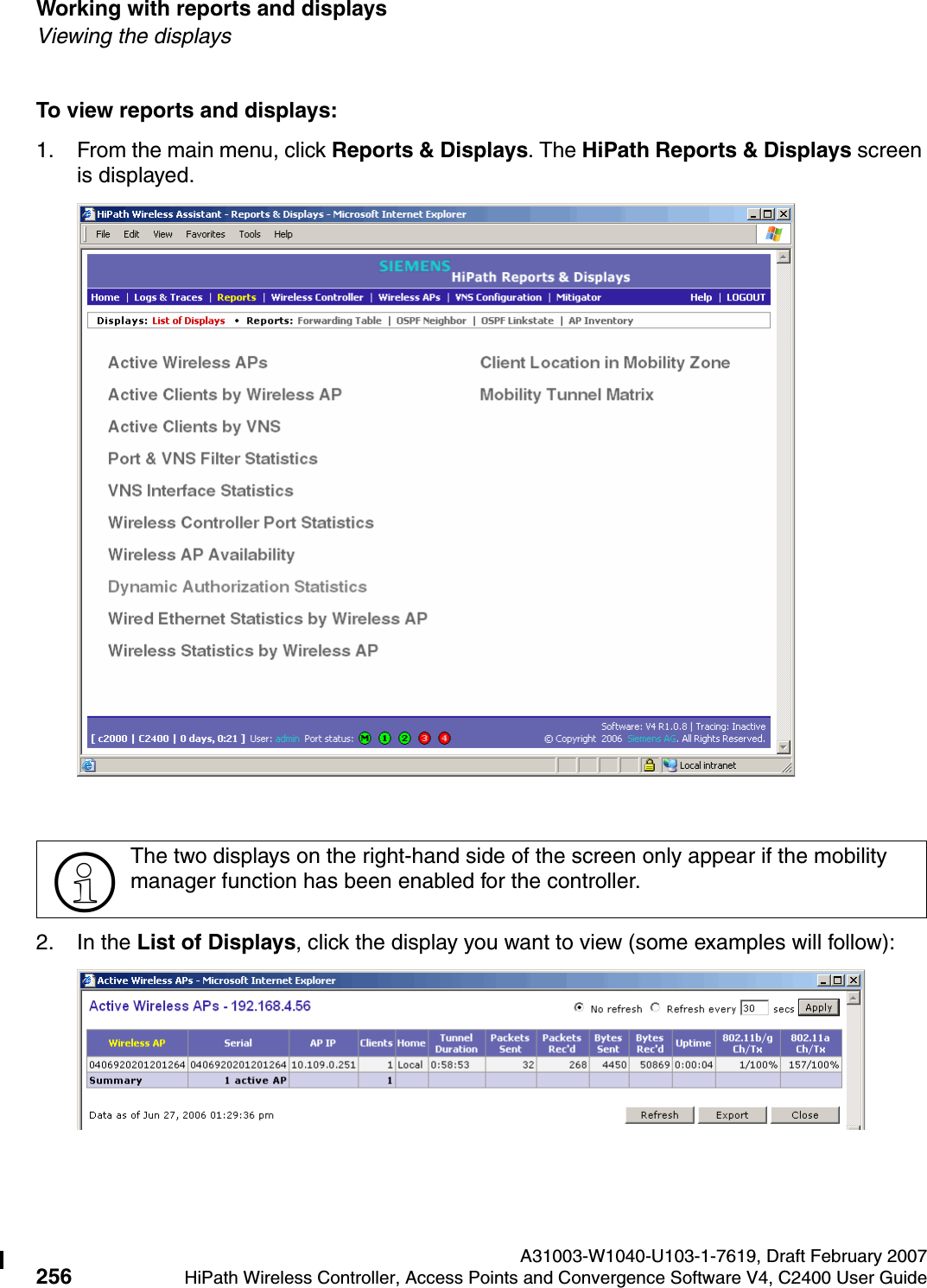
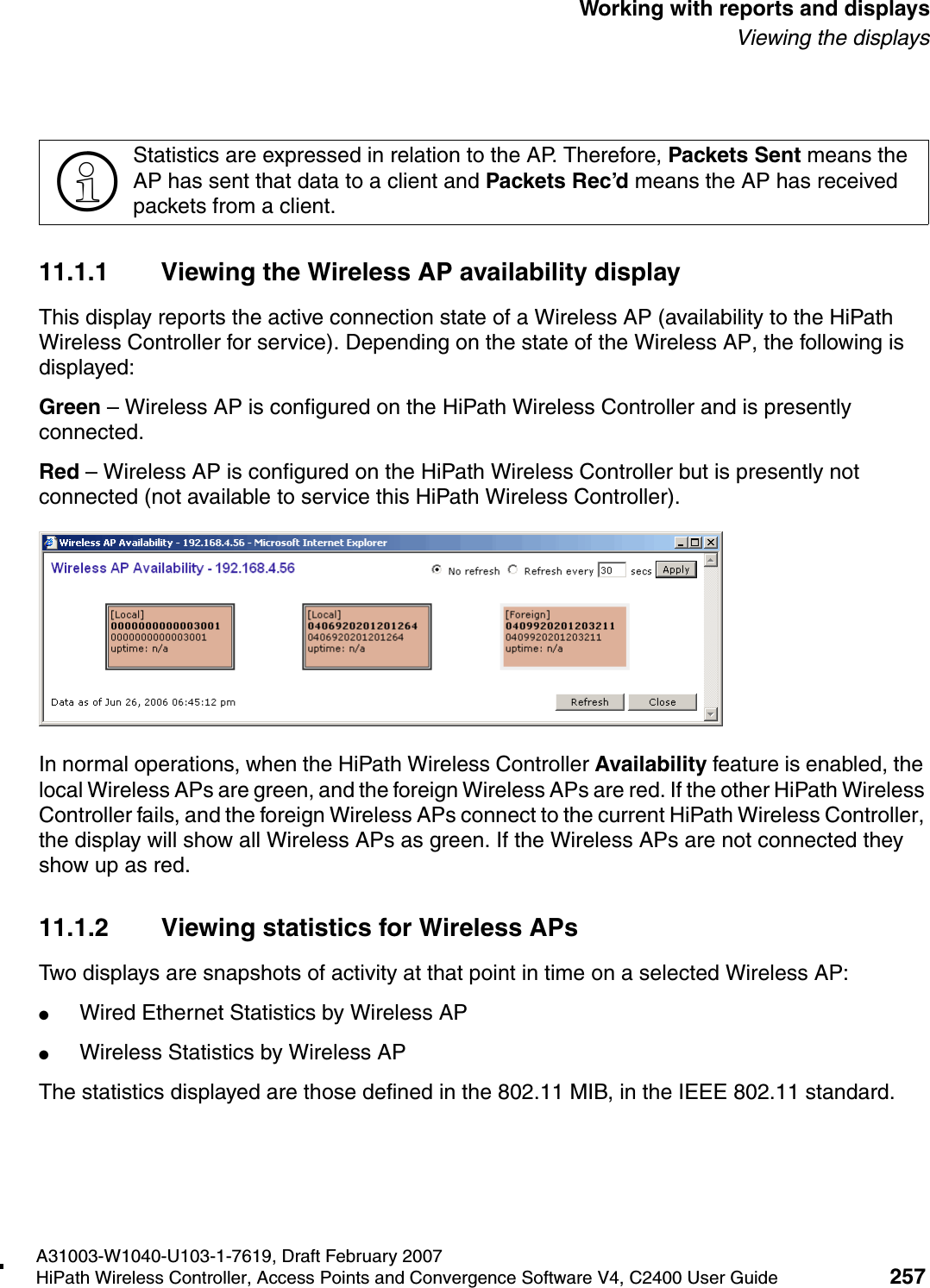
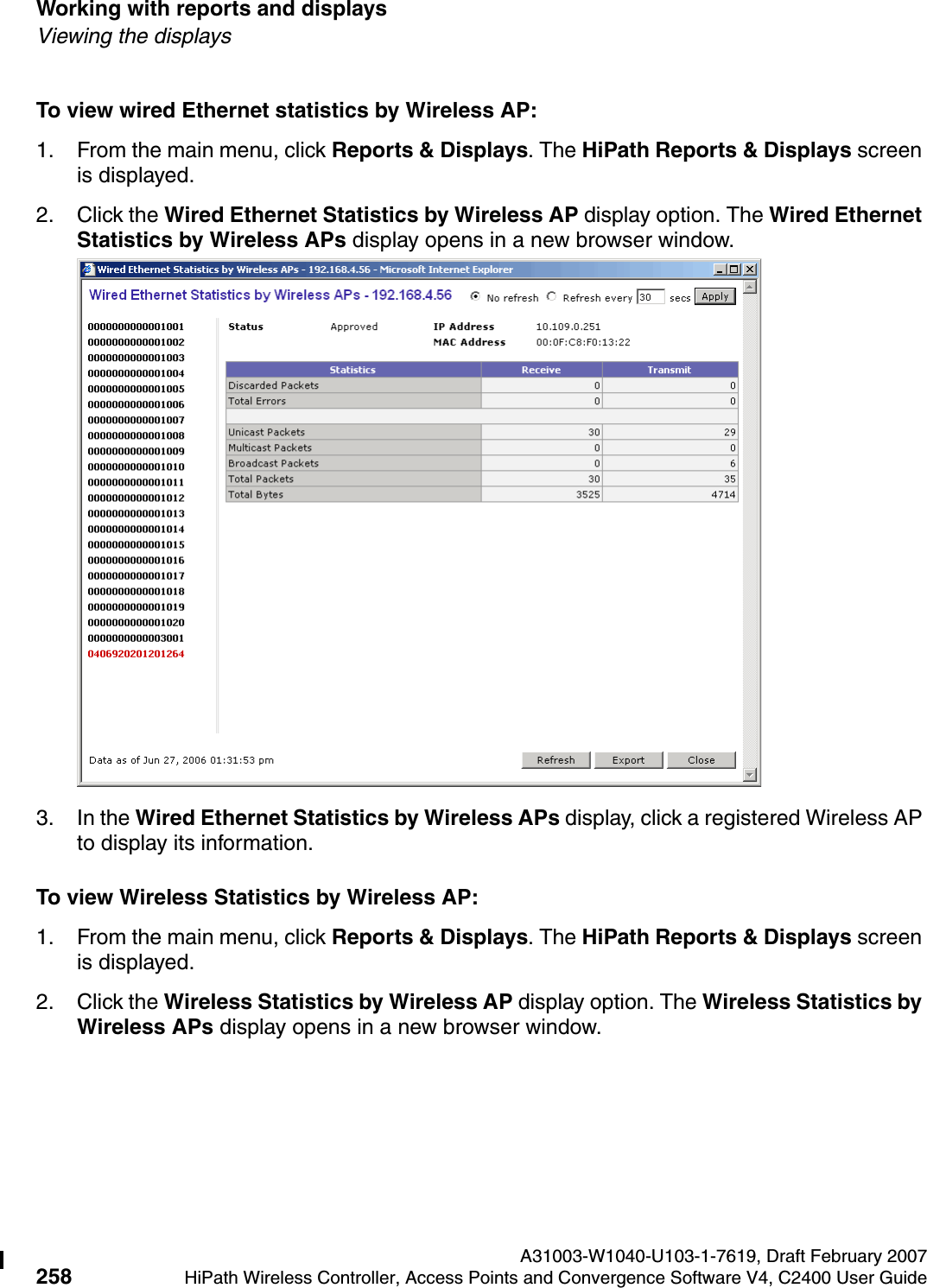
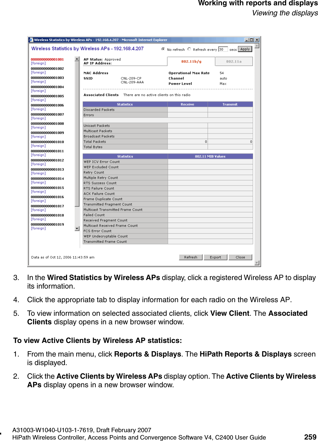
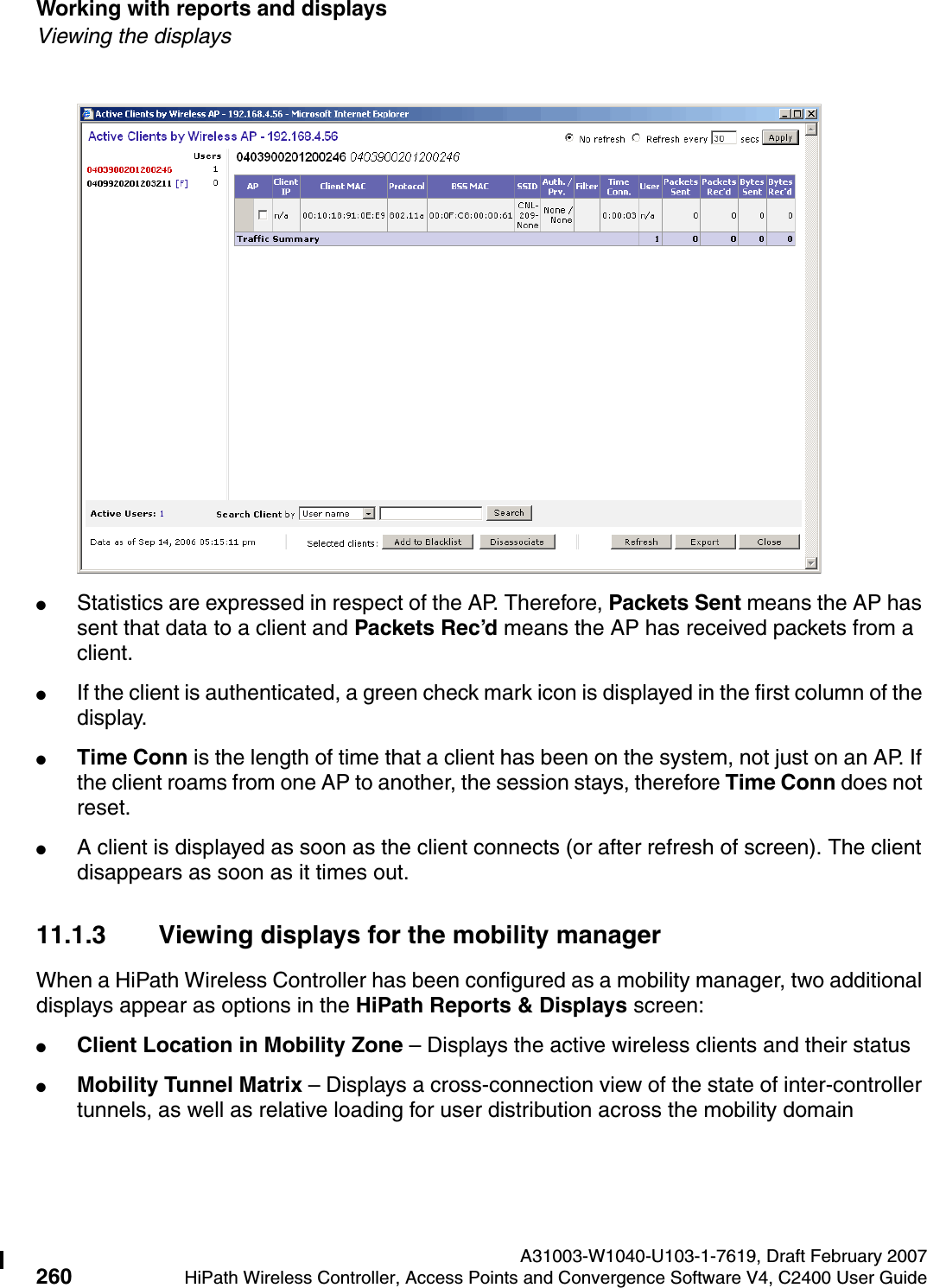
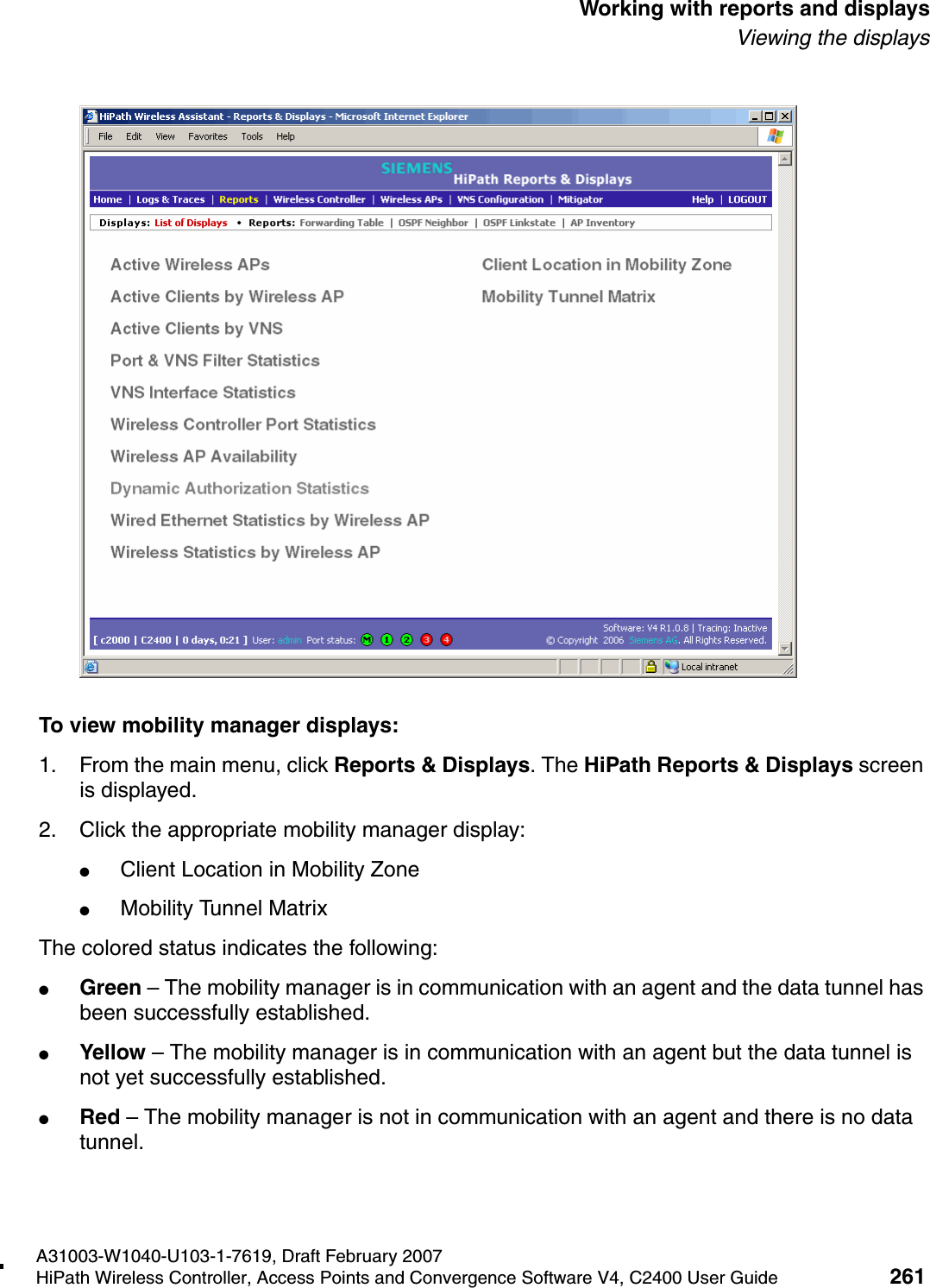
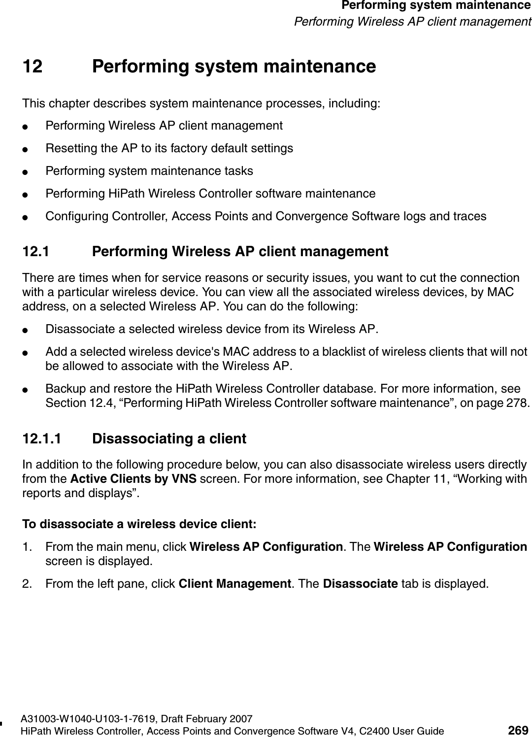
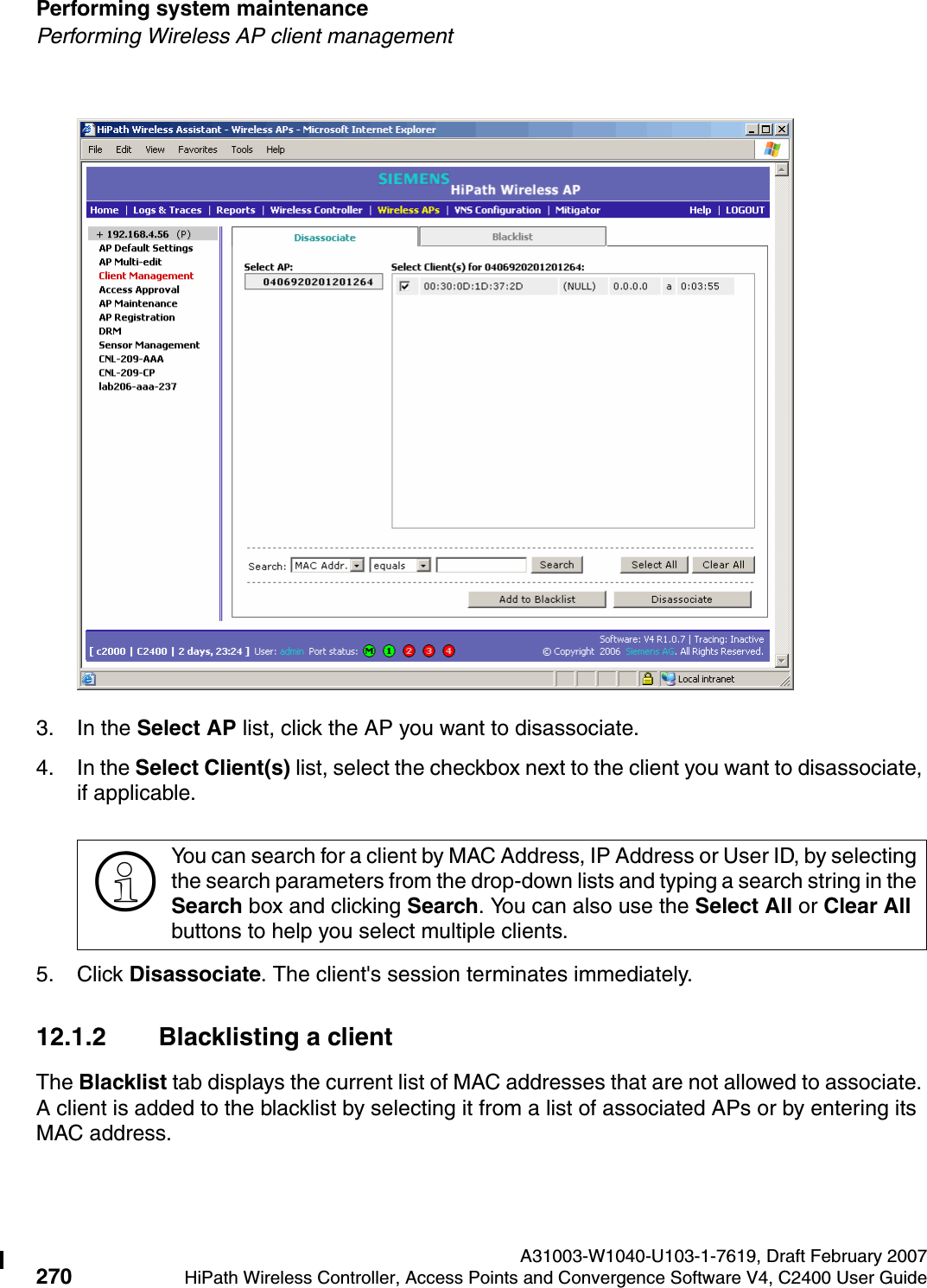
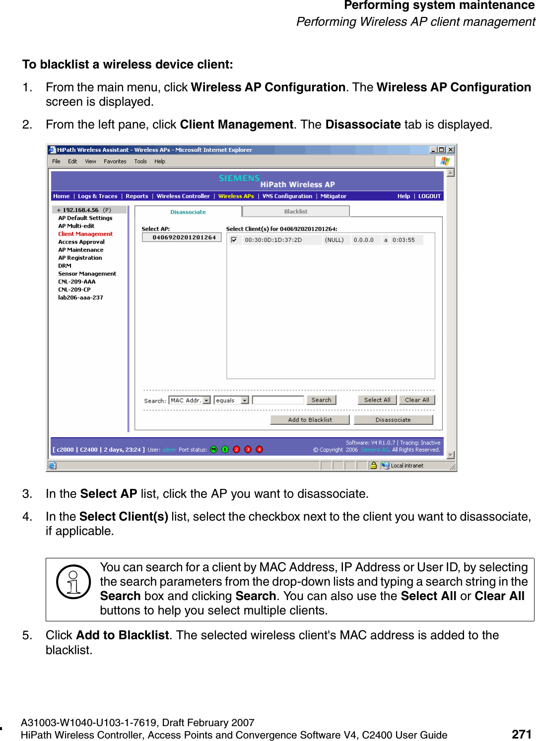
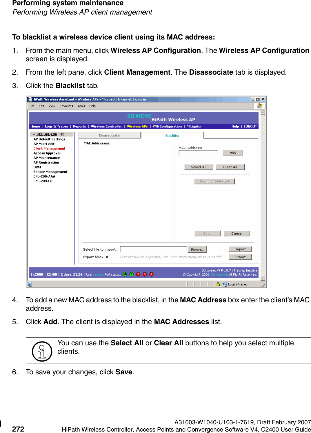
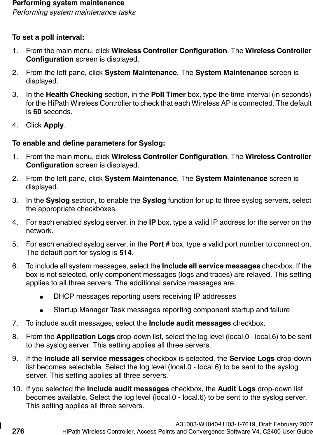
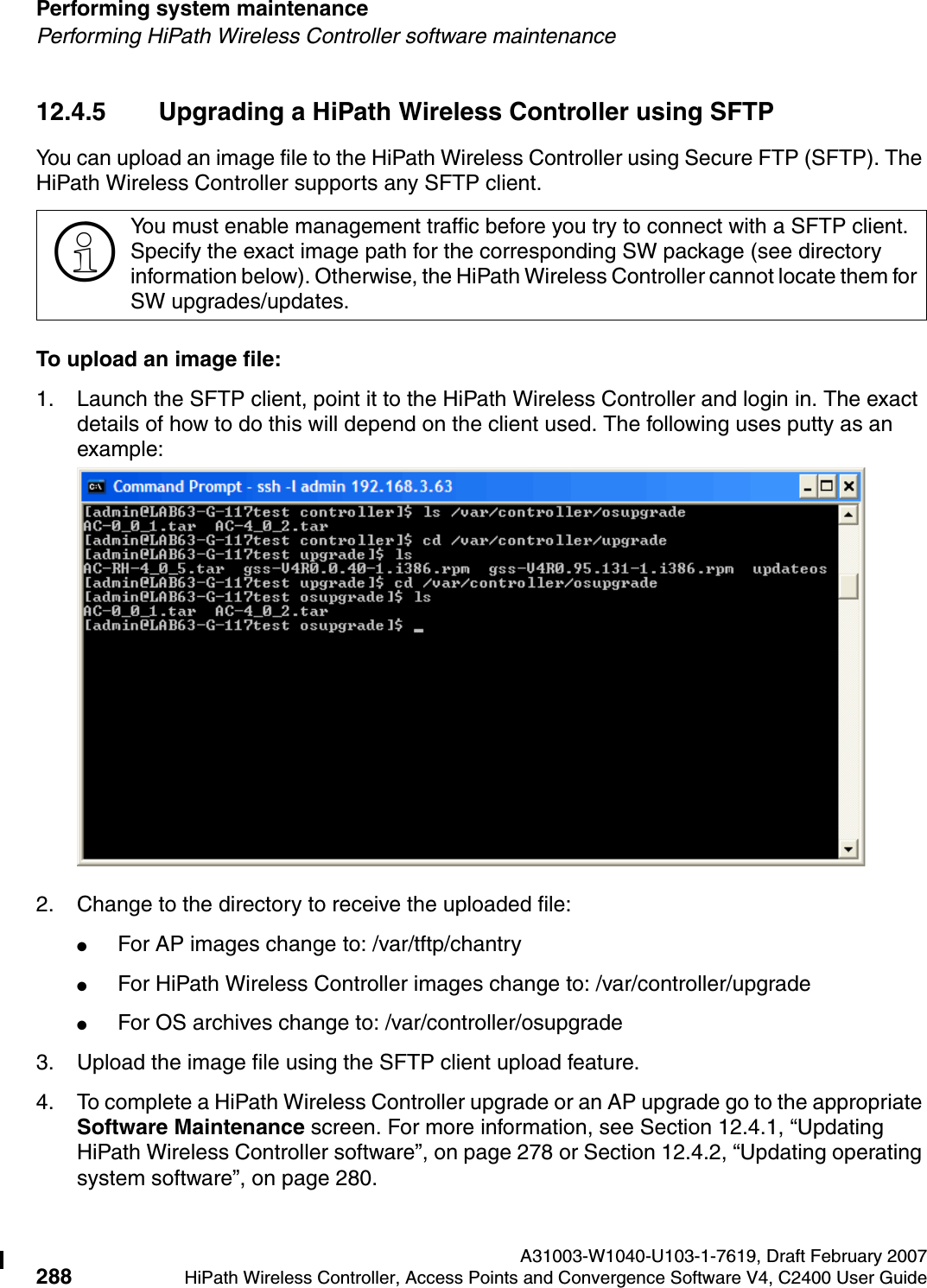
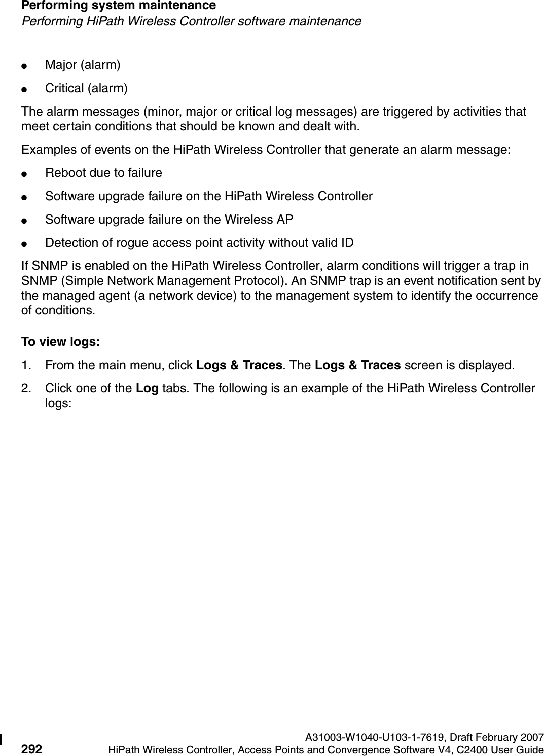
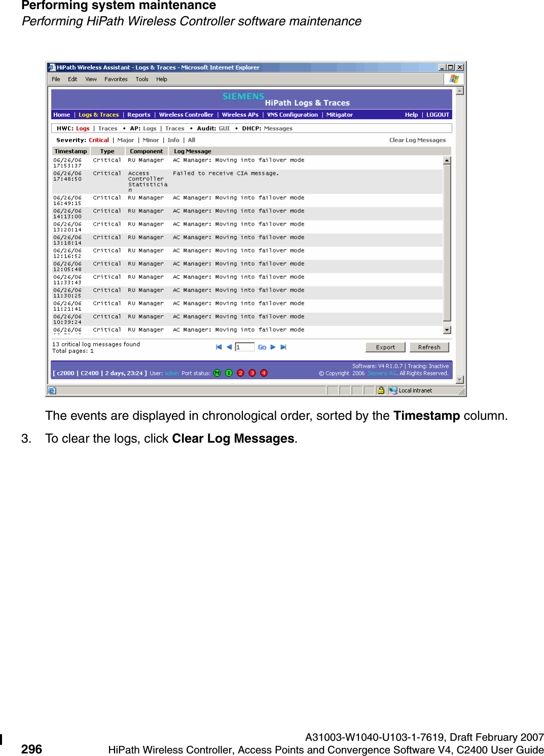
![About this Guide A31003-W1040-U103-1-7619, Draft February 200710 HiPath Wireless Controller, Access Points and Convergence Software V4, C2400 User Guide hwc_pref.fmFormatting conventions●Chapter 7, “Virtual Network configuration”, provides detailed instructions in how to configure a VNS, its topology, authentication, accounting, RADIUS policy, multicast, filtering and privacy. Both Captive Portal and AAA types of VNS are described.●Chapter 8, “Availability, mobility, and controller functionality”, describes how to set up the features that provide availability in the event of a controller failover, and mobility for a wireless device user.●Chapter 9, “Working with third-party APs”, describes how to use the Controller, Access Points and Convergence Software features with third-party wireless access points.●Chapter 10, “Working with the Mitigator”, explains the security tool that scans for, detects and reports on rogue APs.●Chapter 12, “Performing system maintenance”, describes maintenance activities, such as software upgrades on both the HiPath Wireless Controller and the Wireless AP. This chapter also includes information on the logs, traces, reports and displays available.●Chapter 13, “Glossary”, contains a list of terms and definitions for the HiPath Wireless Controller and the Wireless AP as well as standard industry terms used in this guide.●Appendix A, “System states and LEDs”, provides a reference on the LED displays and their significance.1.3 Formatting conventionsThe HiPath Wireless Controller, Access Points and Convergence Software documentation uses the following formatting conventions to make it easier to find information and follow procedures:●Bold text is used to identify components of the management interface, such as menu items and section of pages, as well as the names of buttons and text boxes.For example: Click Logout.●Monospace font is used in code examples and to indicate text that you type.For example: Type https://<hwc-address>[:mgmt-port>]●The following symbols are used to draw your attention to additional information:>Notes identify useful information that is not essential, such as reminders, tips, or other ways to perform a task.7Warnings identify information that is essential. Ignoring a warning can adversely affect the operation of your equipment or software.](https://usermanual.wiki/Chantry-Networks/APXXX1.USERS-MANUAL-1/User-Guide-755957-Page-10.png)
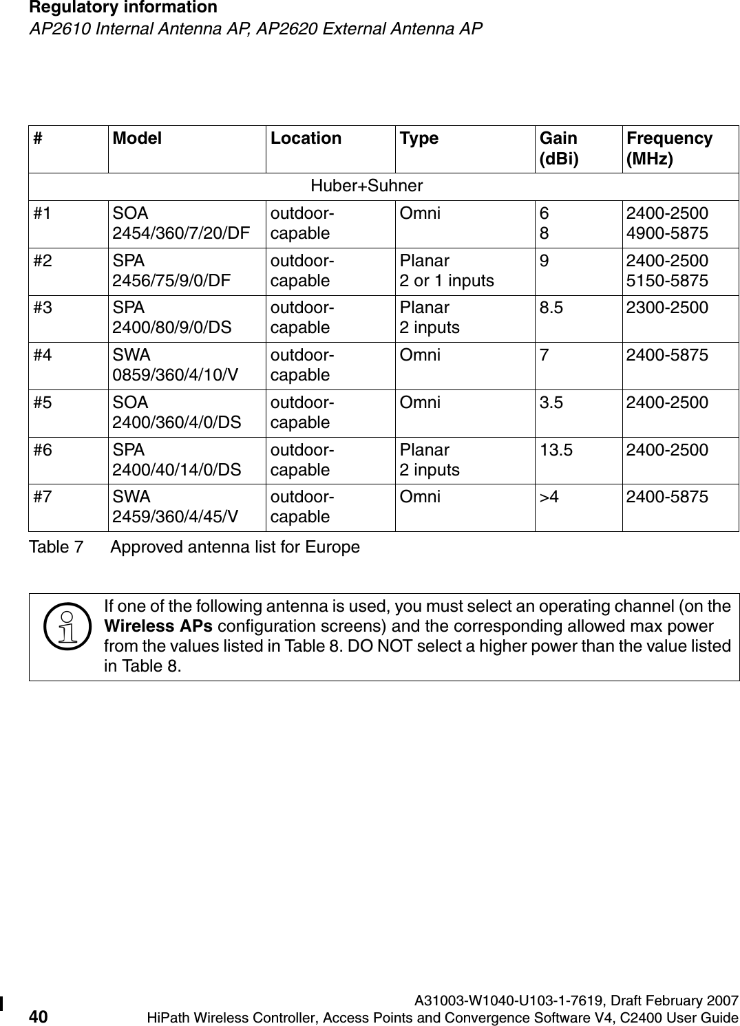
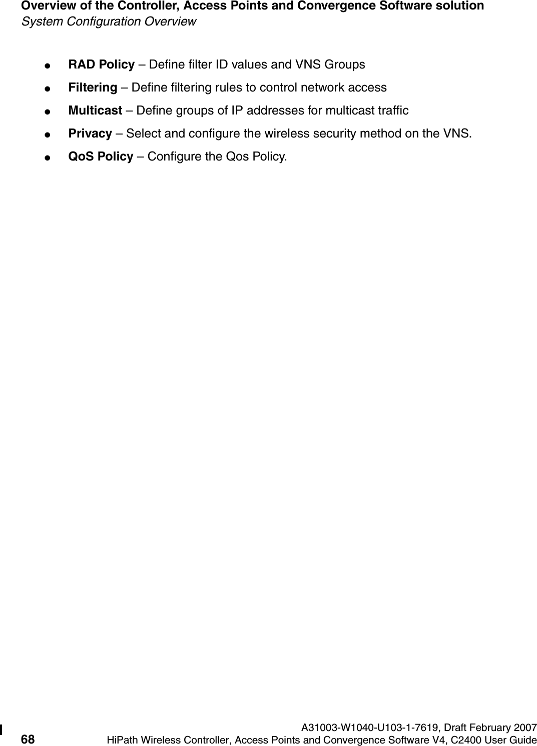
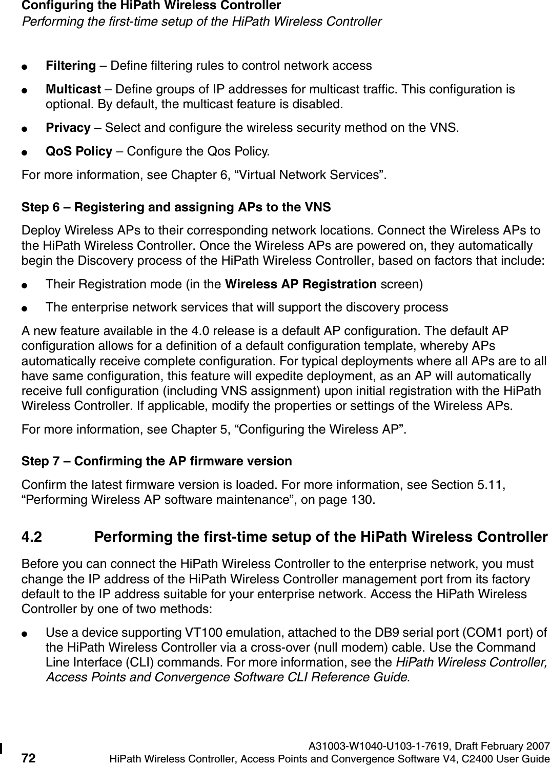
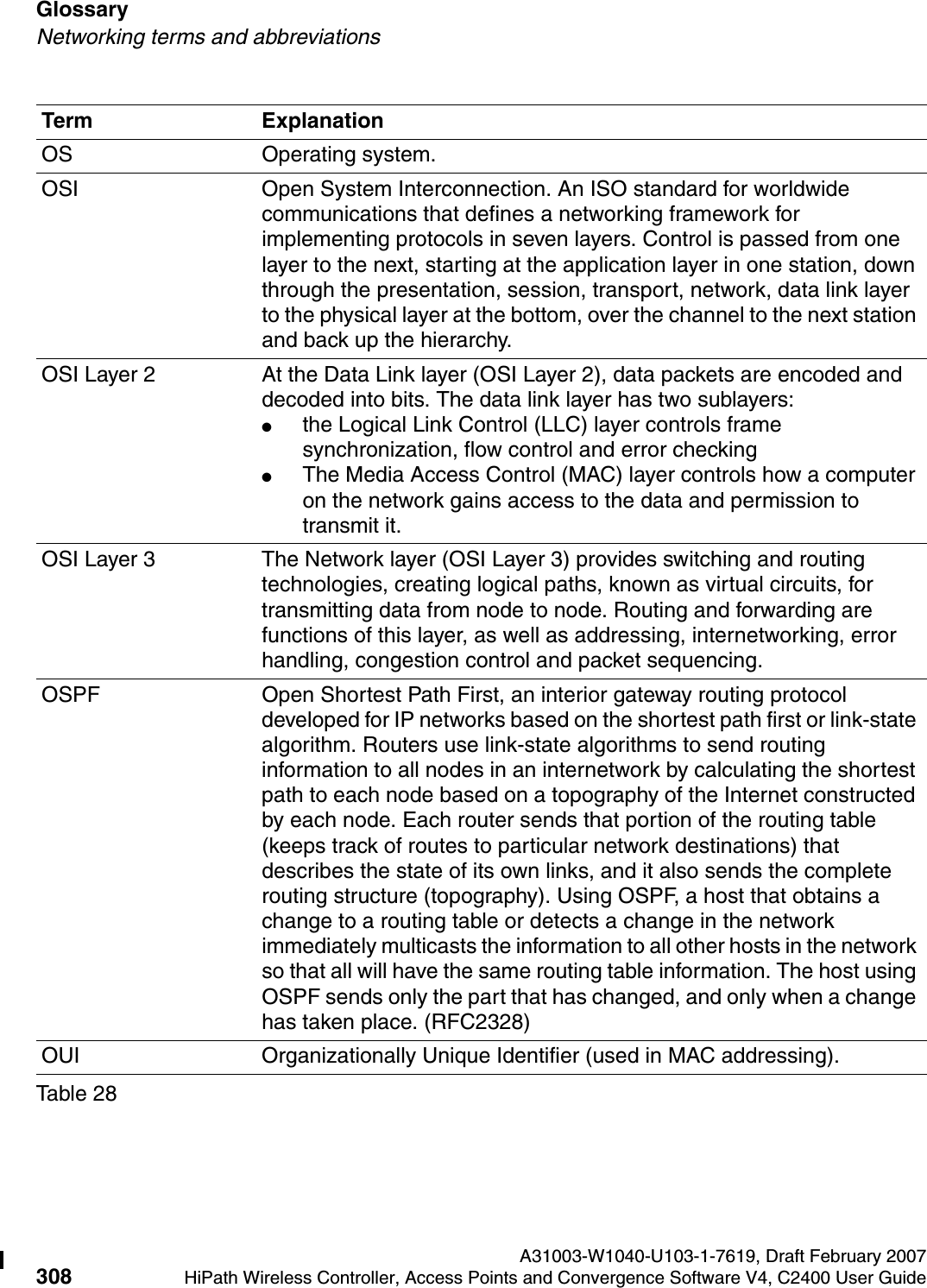
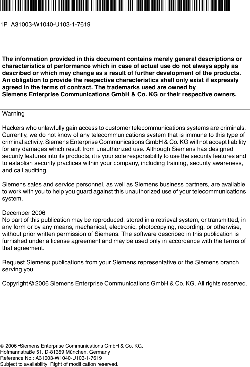
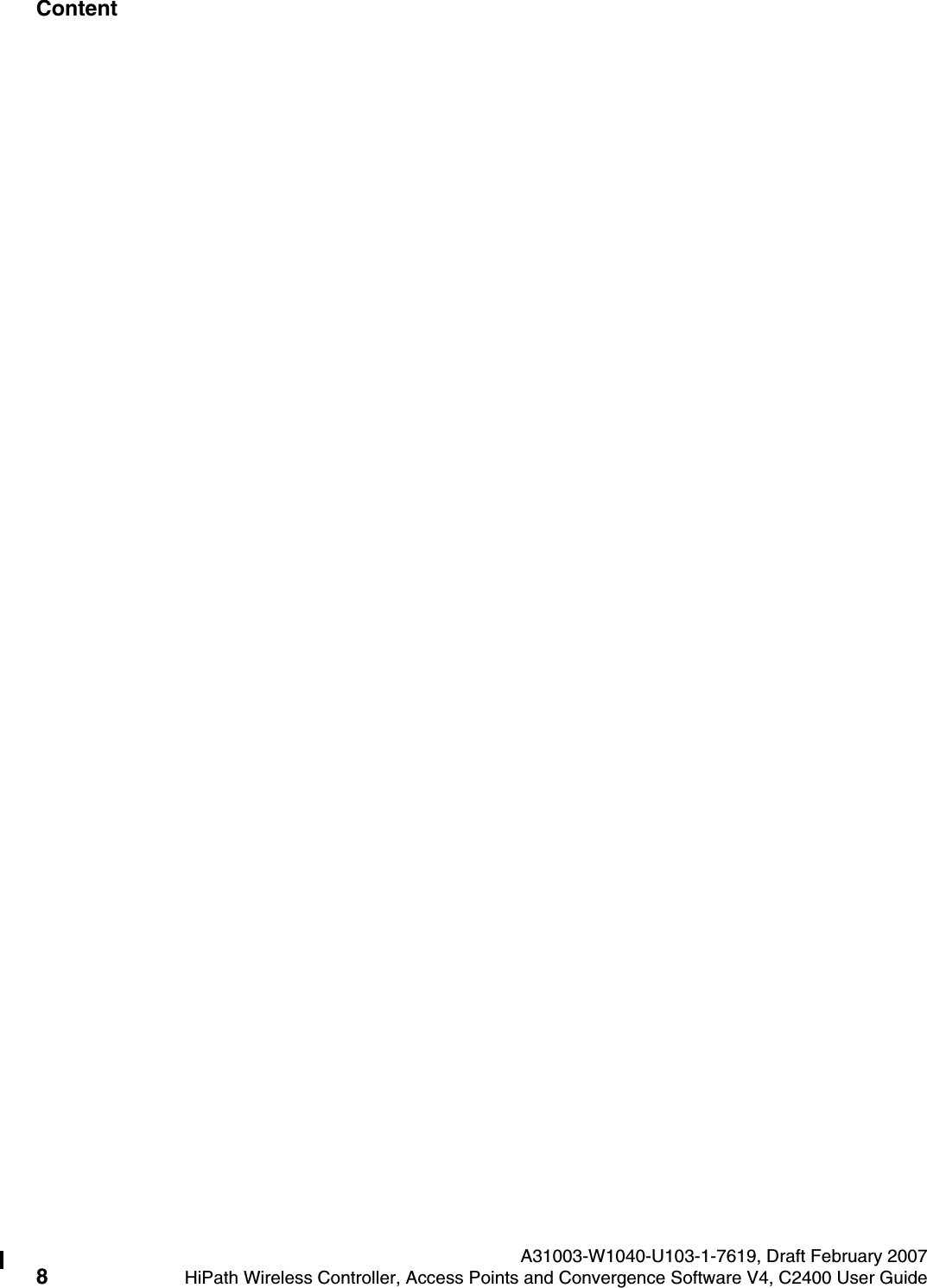
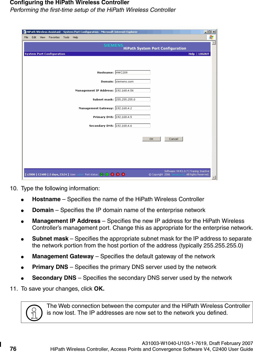
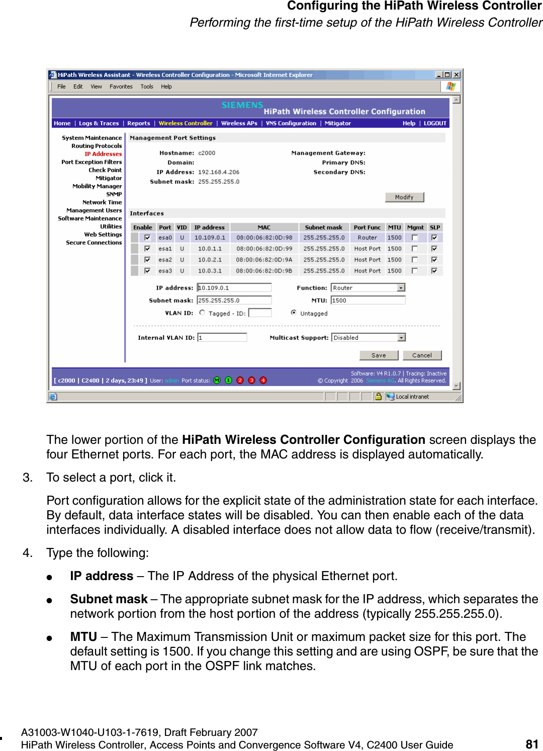
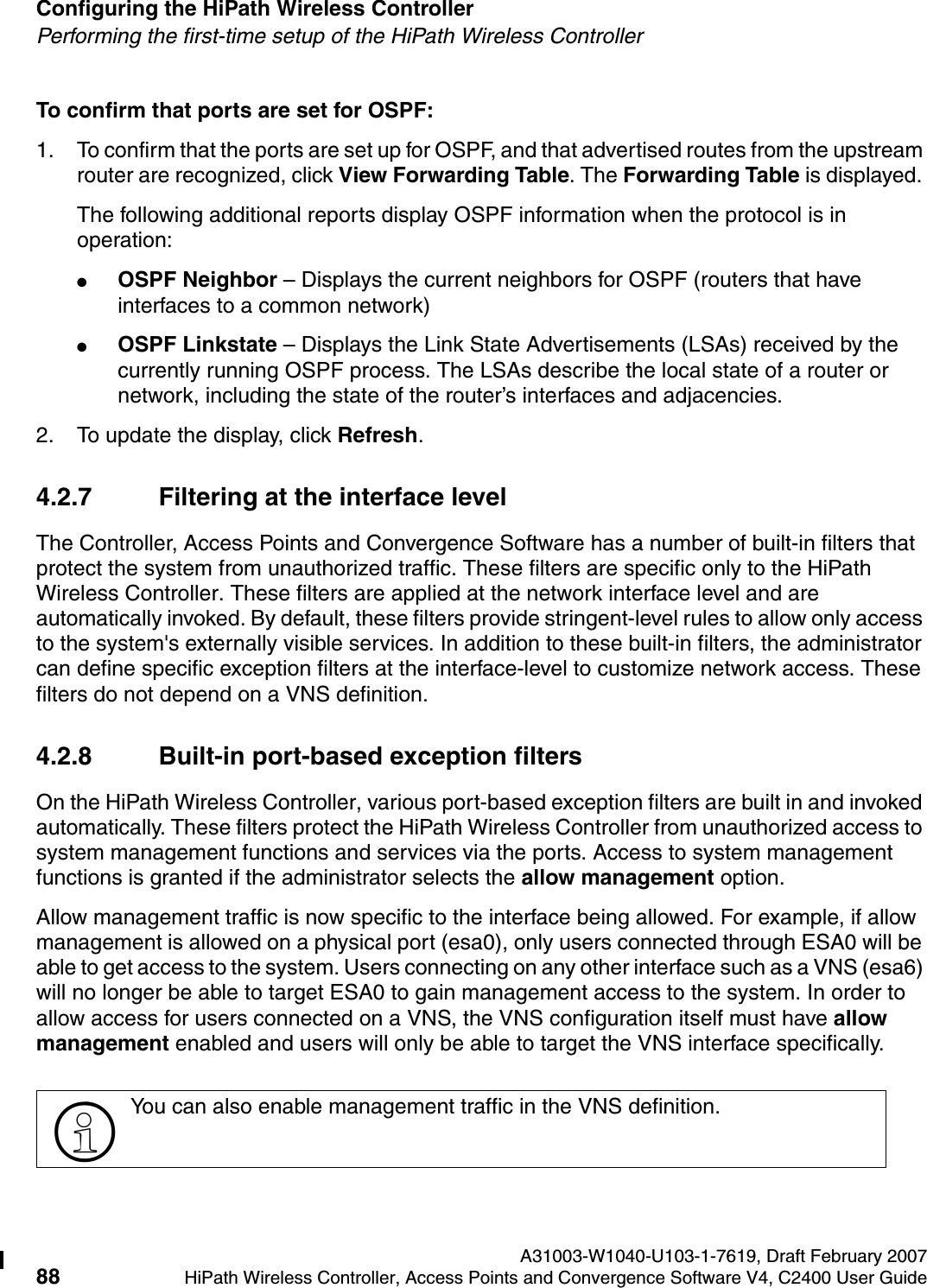
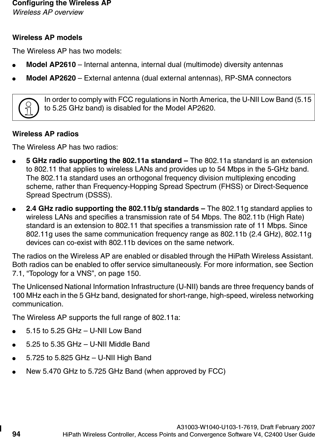
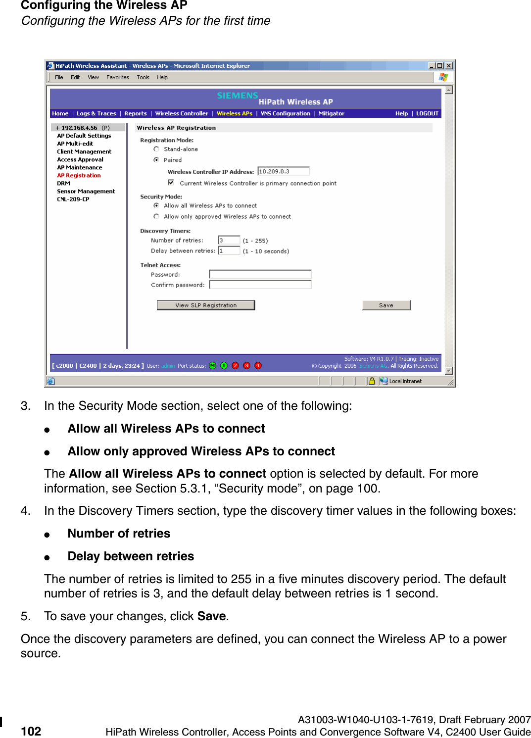
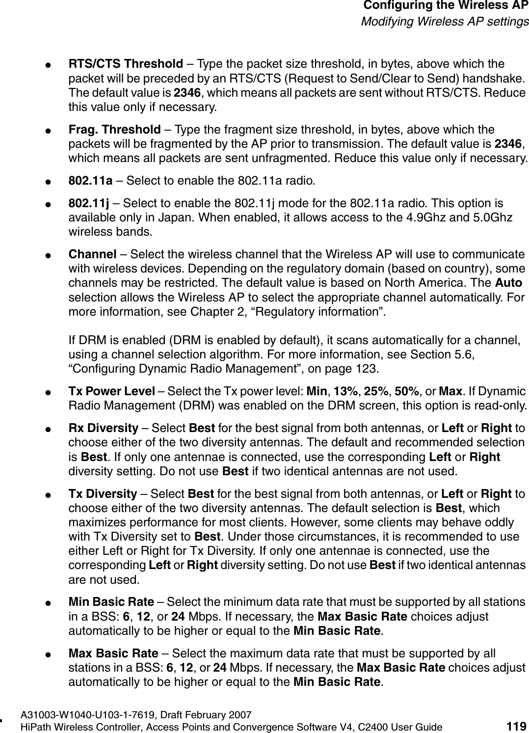
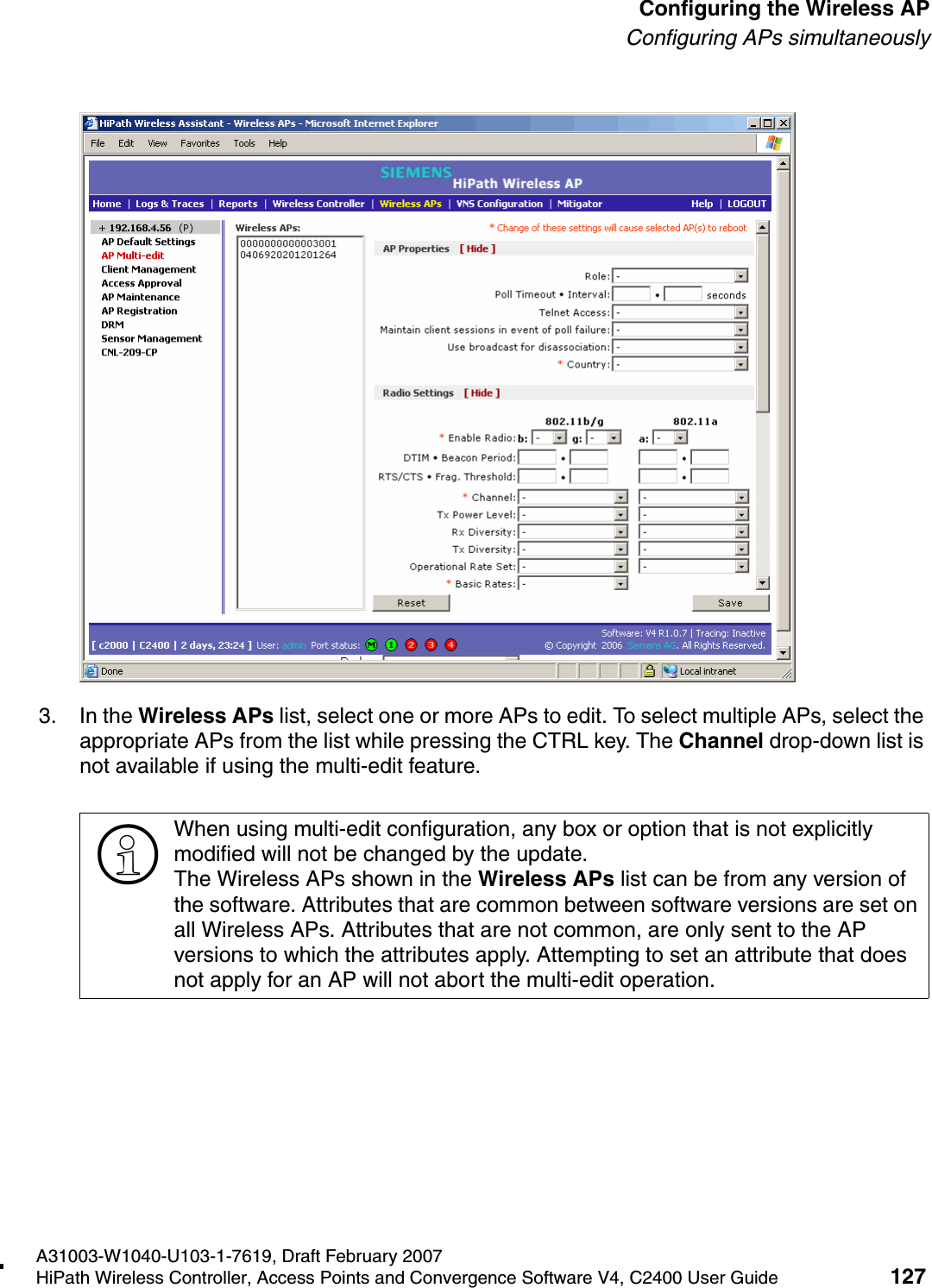
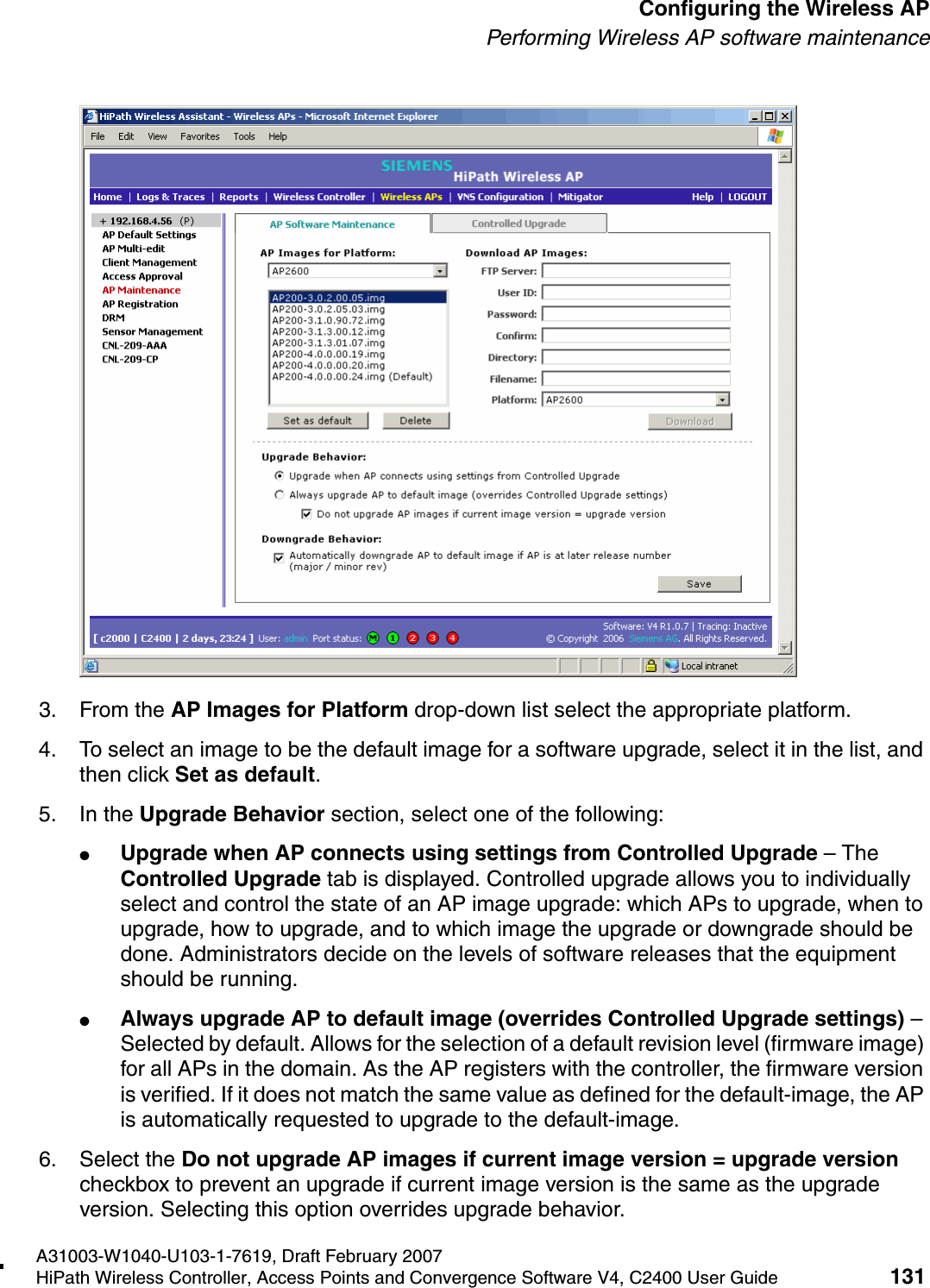
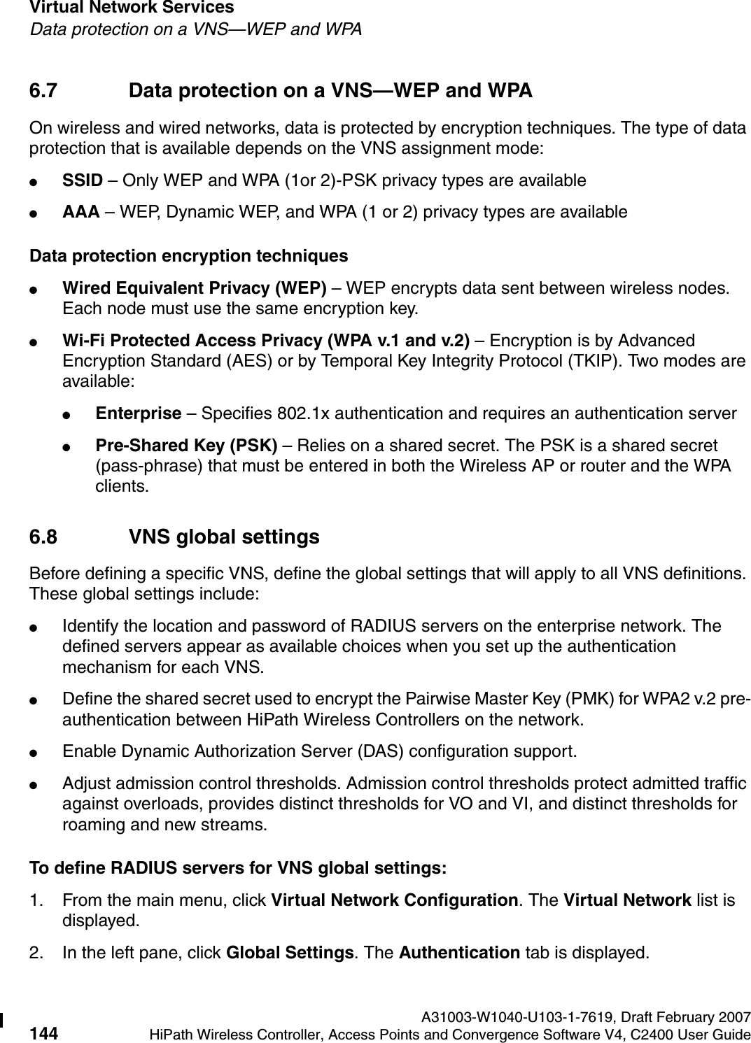
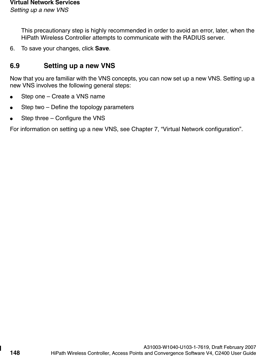
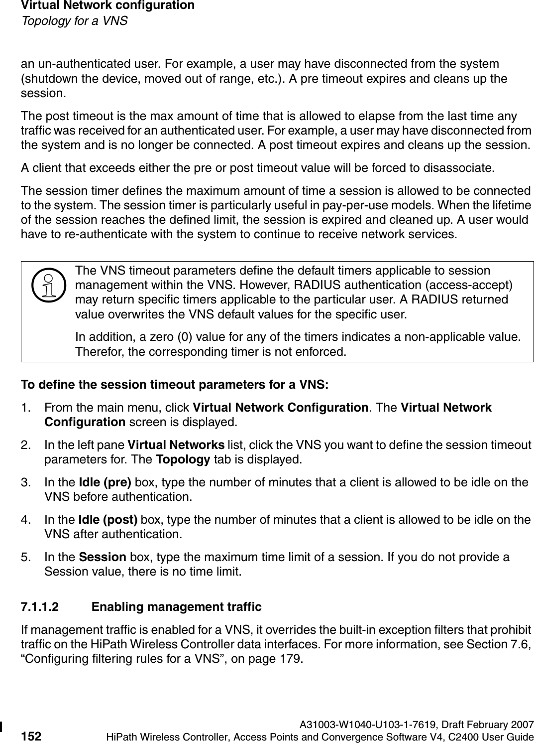
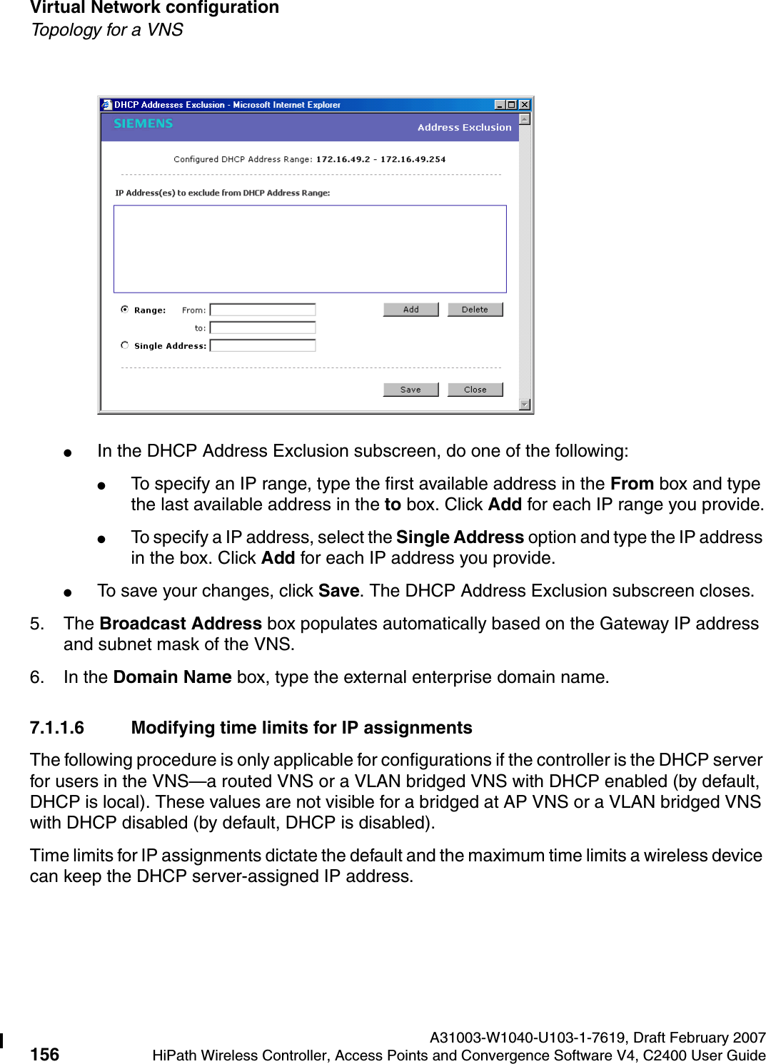
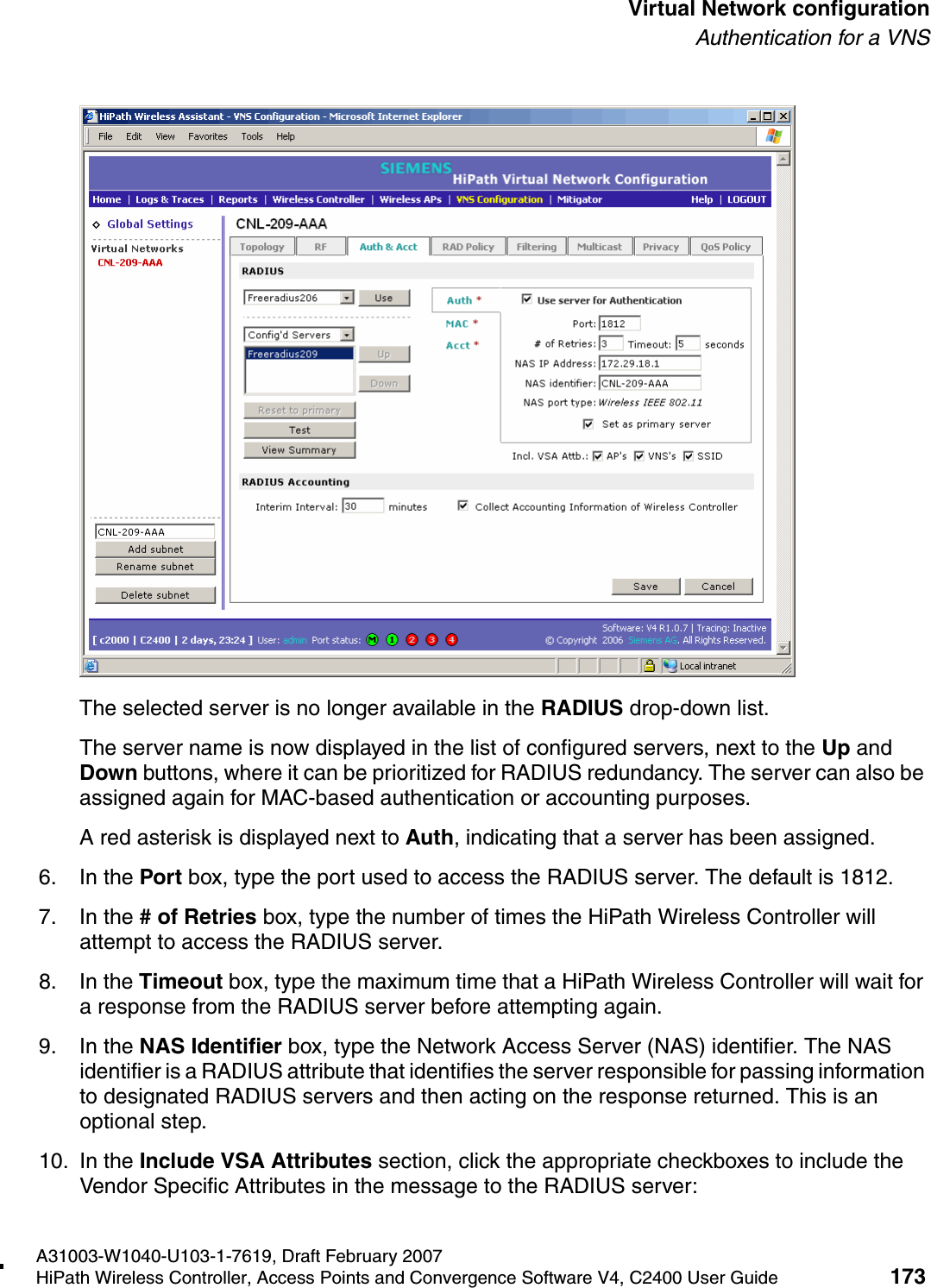
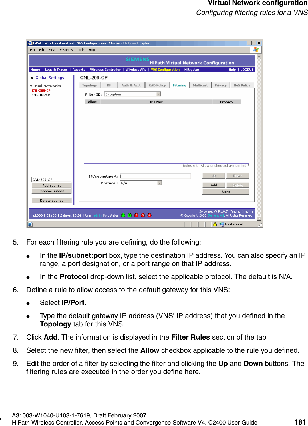
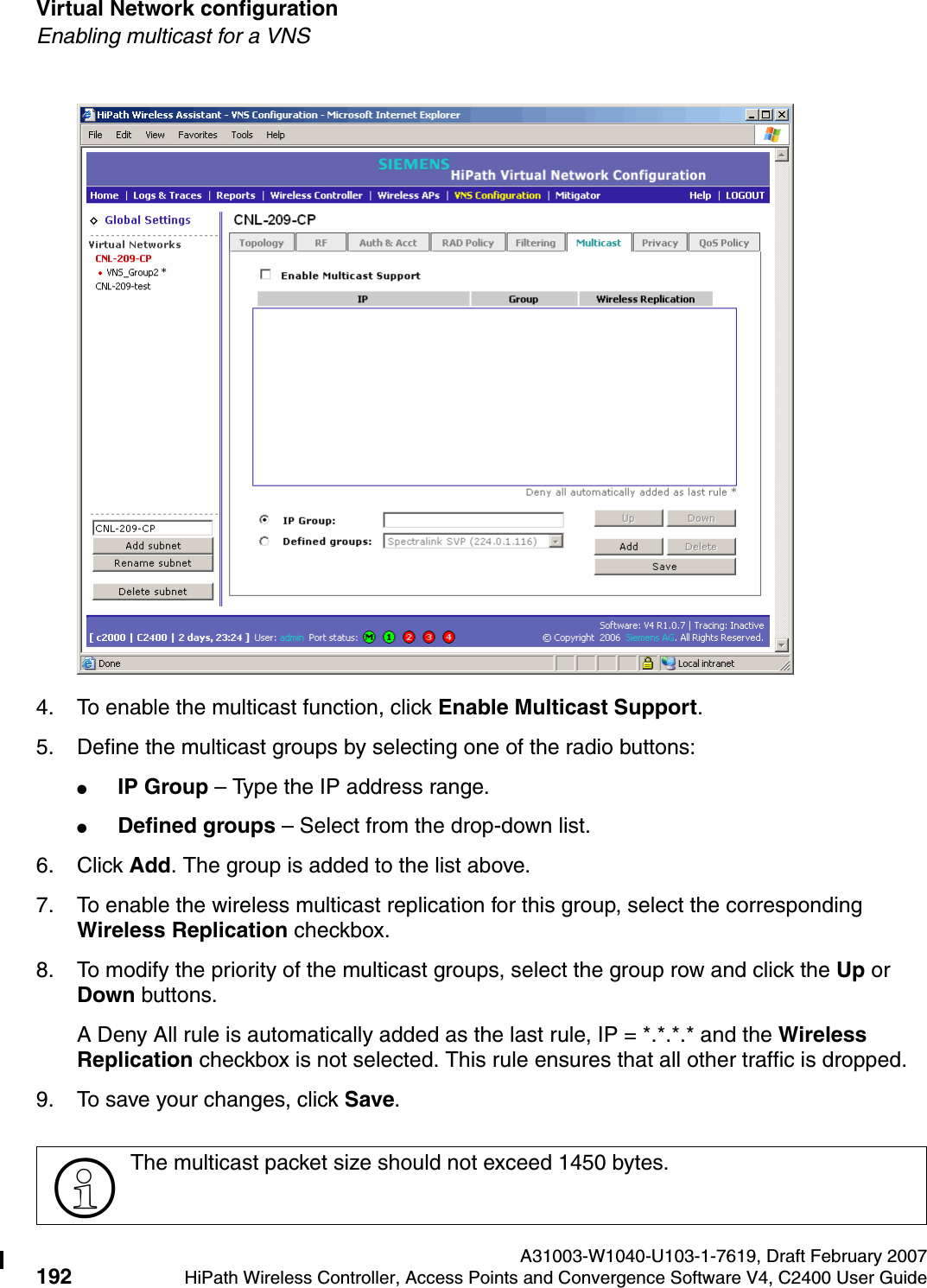
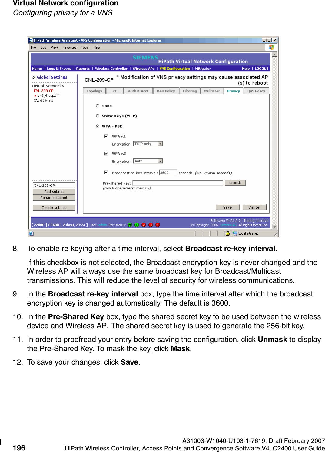
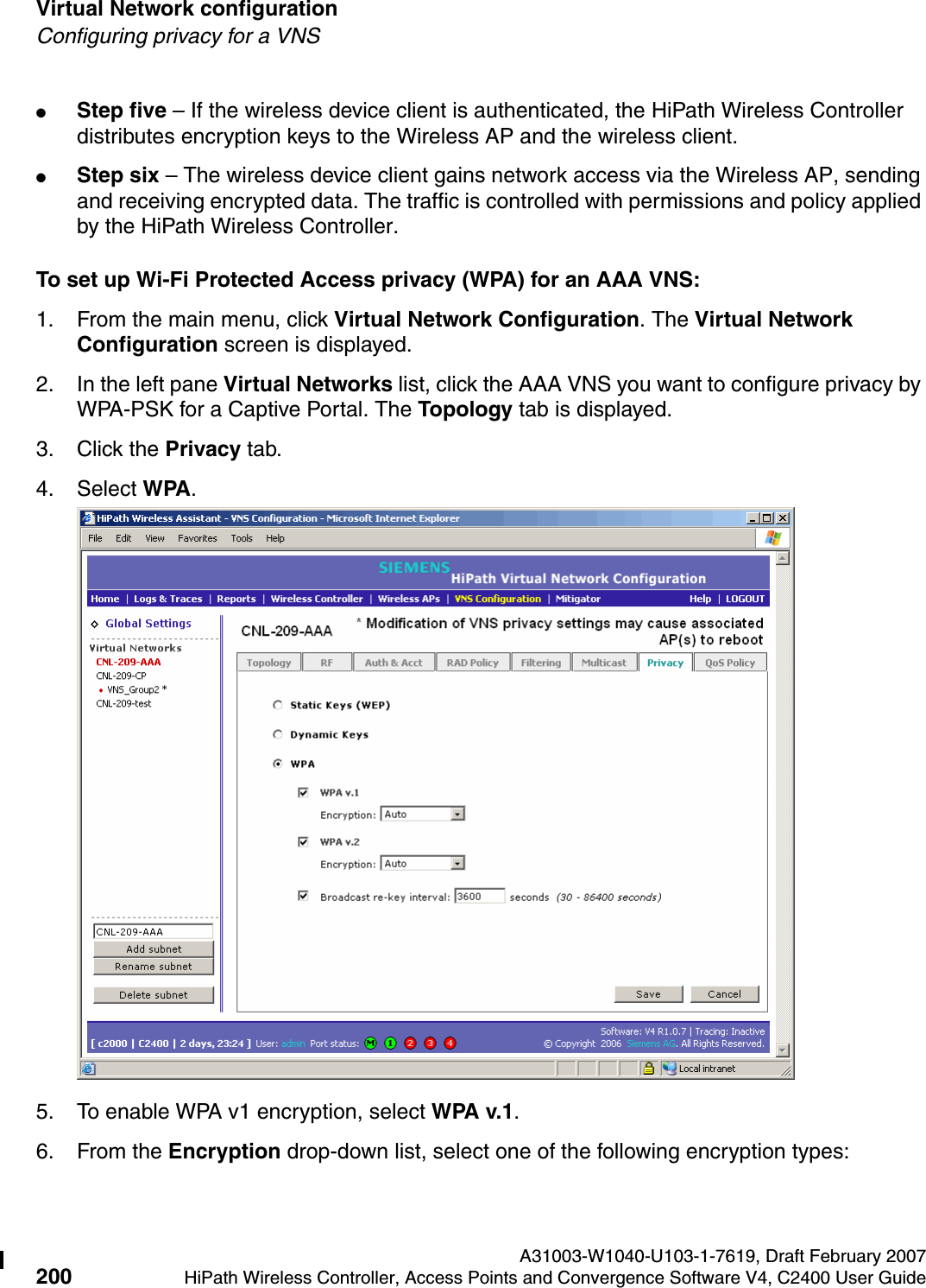
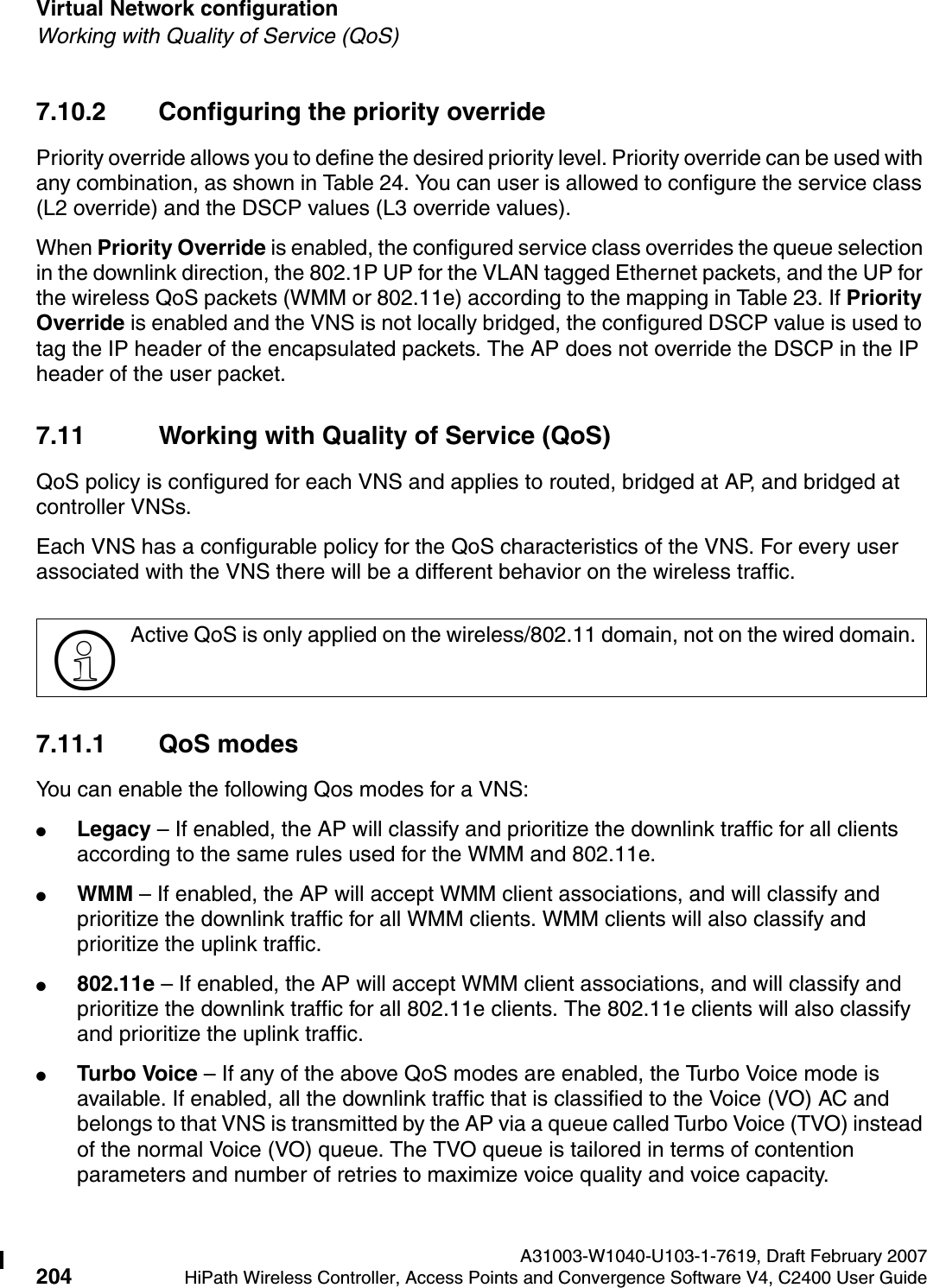
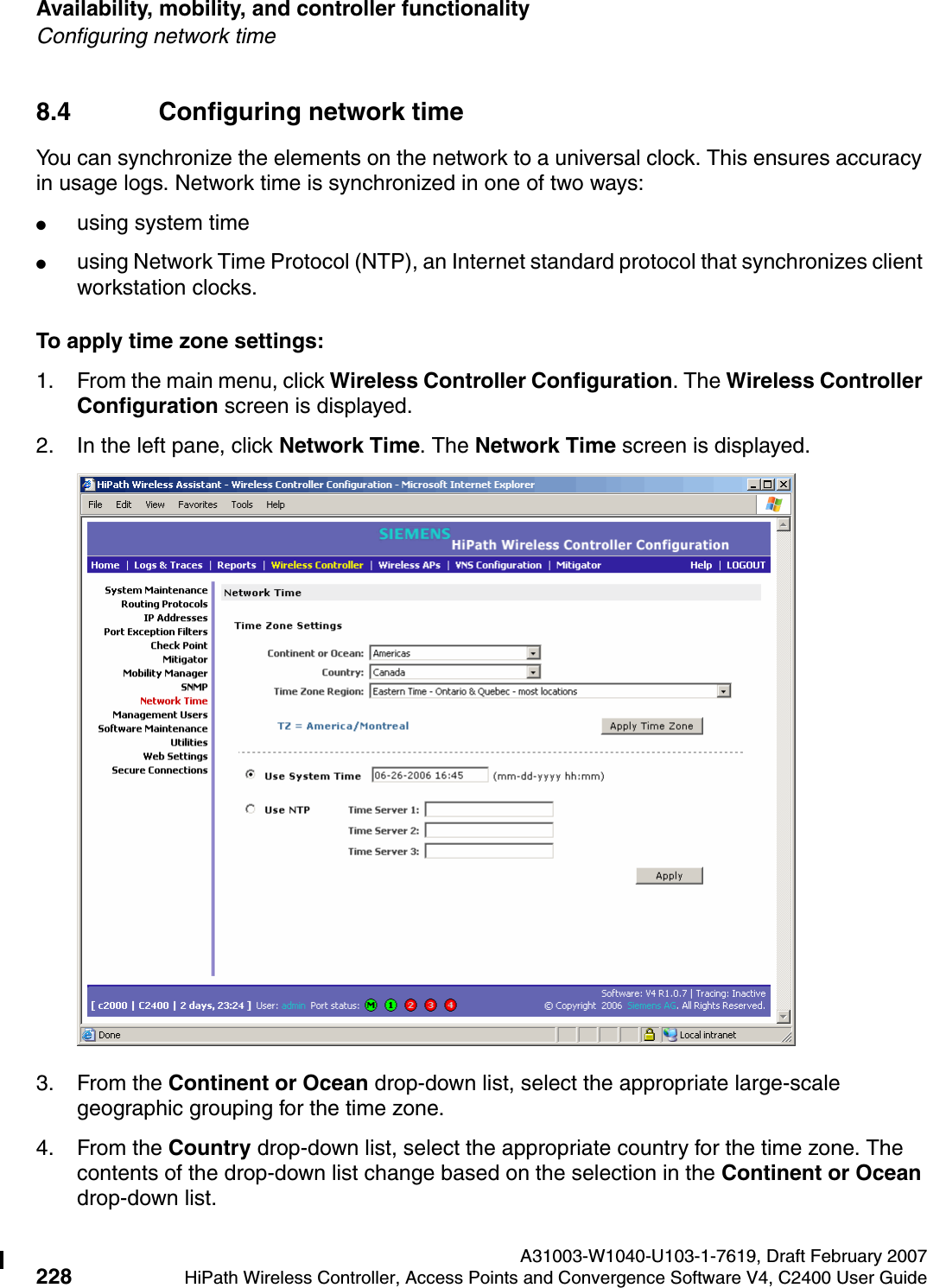
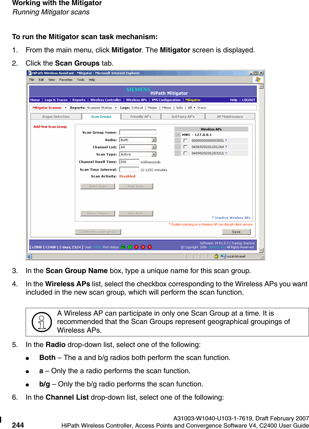
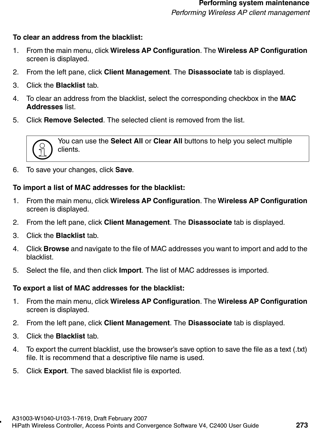
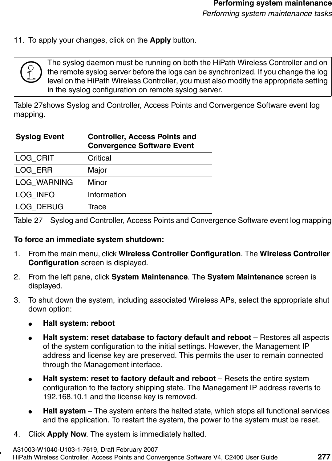
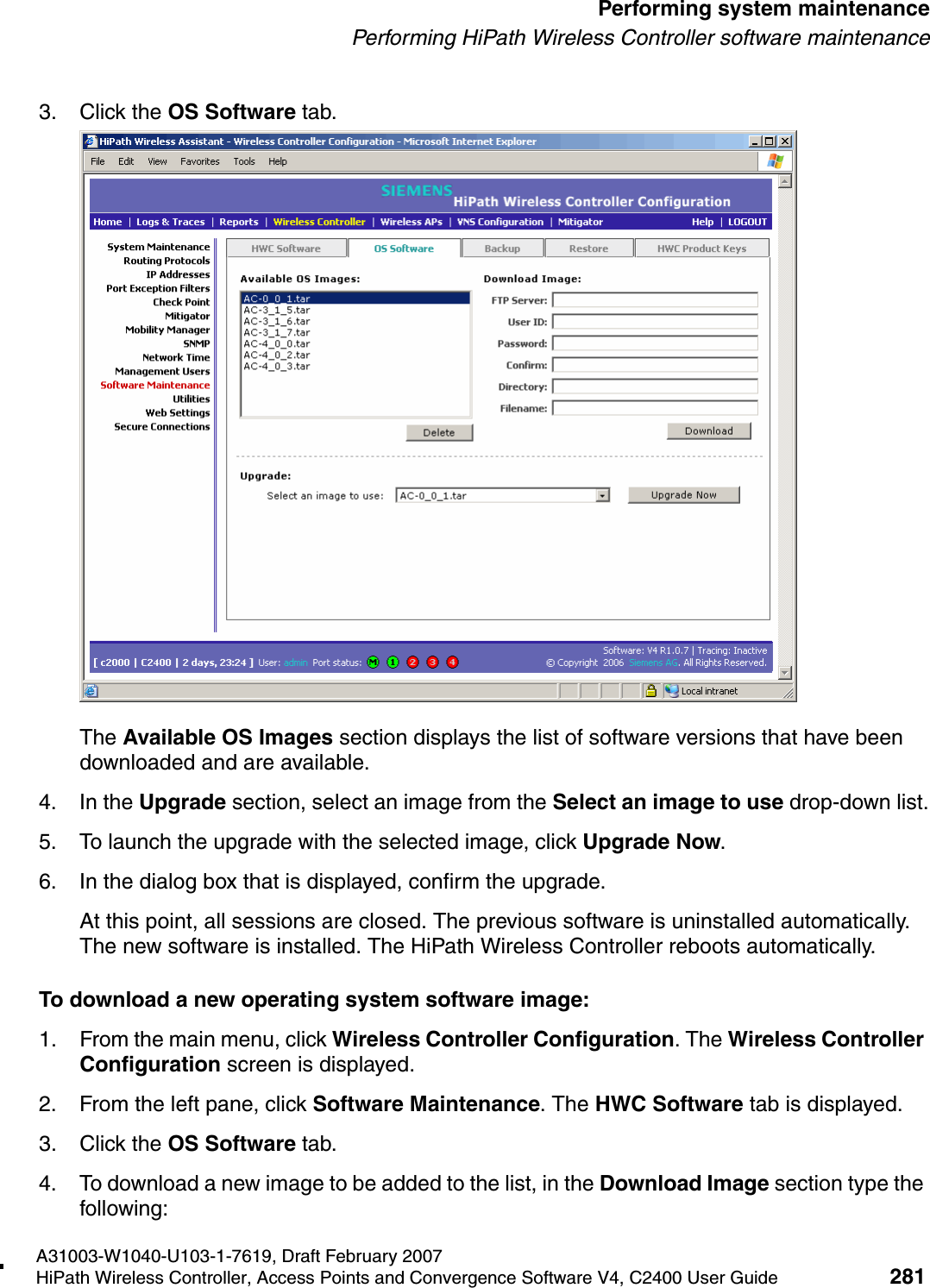
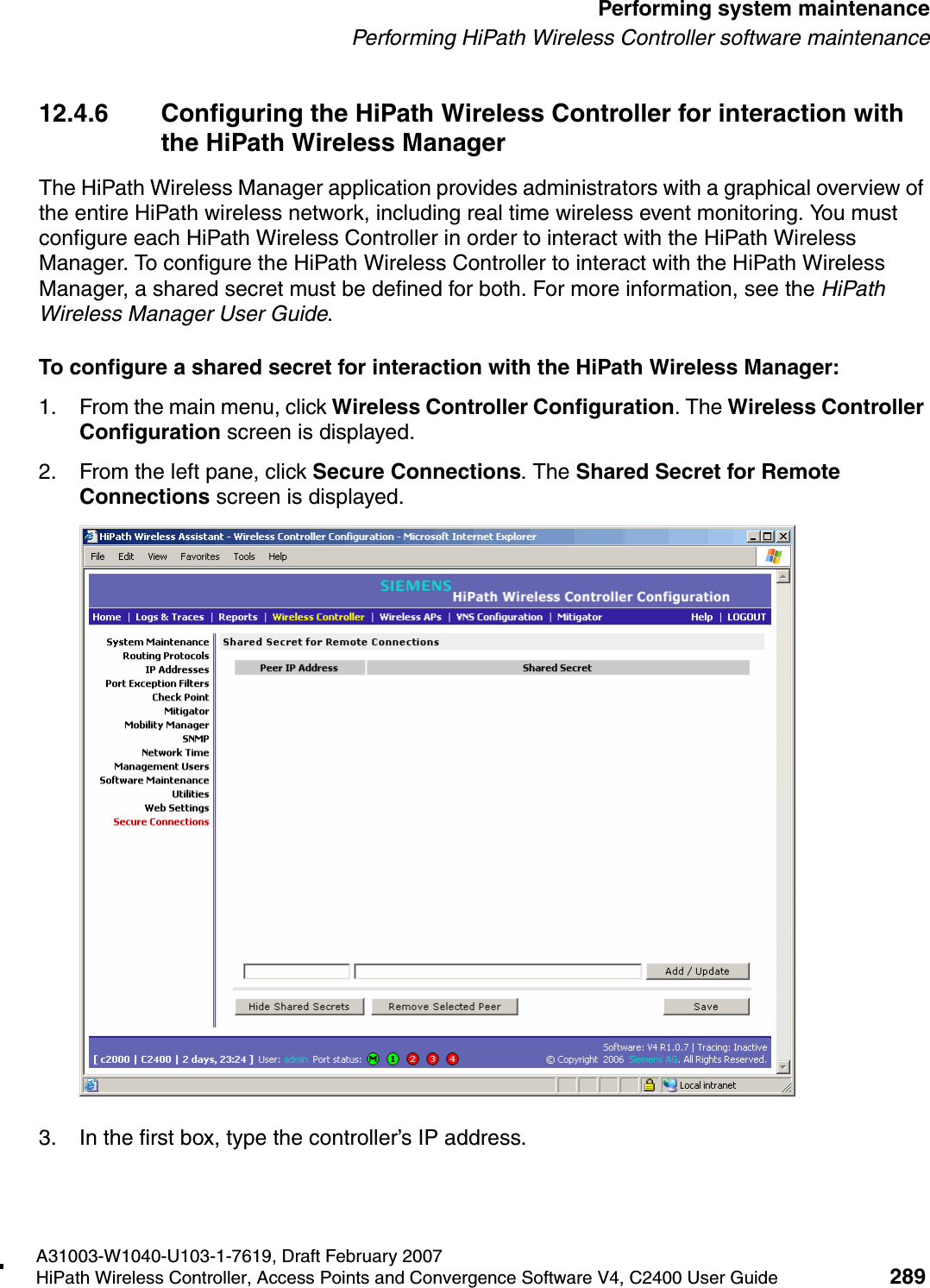
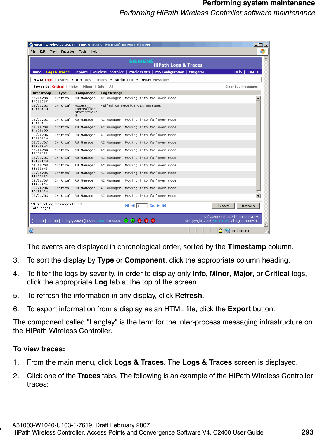
![Configuring the HiPath Wireless Controller A31003-W1040-U103-1-7619, Draft February 200774 HiPath Wireless Controller, Access Points and Convergence Software V4, C2400 User Guide hwc_startup.fmPerforming the first-time setup of the HiPath Wireless Controller6. Click Login. The HiPath Wireless Assistant main menu screen is displayed. 7. From the main menu, click Wireless Controller Configuration. The HiPath Wireless Controller Configuration screen is displayed.8. In the left pane, click IP Addresses. The factory default settings for the HiPath Wireless Controller are displayed.>In the footer of the HiPath Wireless Assistant, the following is displayed:●[host name | product name | up time]For example, [c2000 | C2400 | 2 days, 23:24]. If there is no key (unlicensed), the product name will not be displayed.●User is the user id you used to login in. For example, admin.●Port Status is the connectivity state of the port. M is for the Management interface, which is on eth0 and the numbered lights reflect the esa ports on the system. Green indicates the interface is up and running. Red indicates the interface is down.](https://usermanual.wiki/Chantry-Networks/APXXX1.USERS-MANUAL-1/User-Guide-755957-Page-74.png)
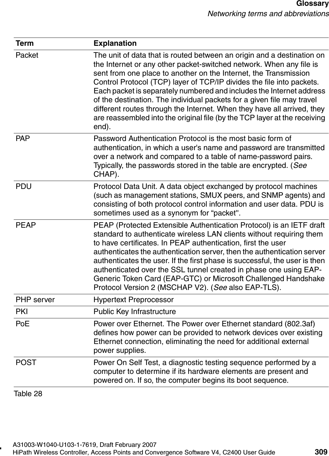
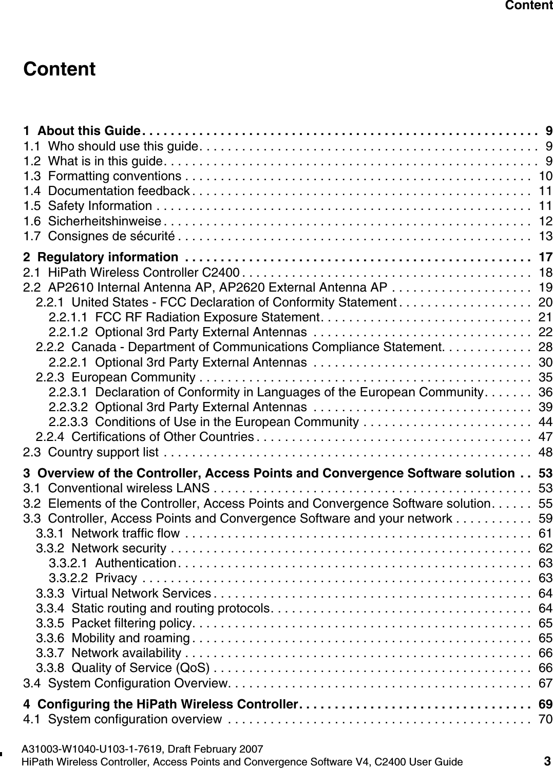
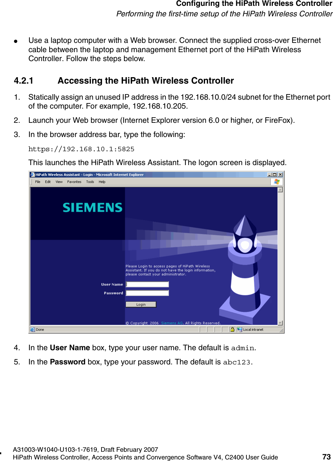
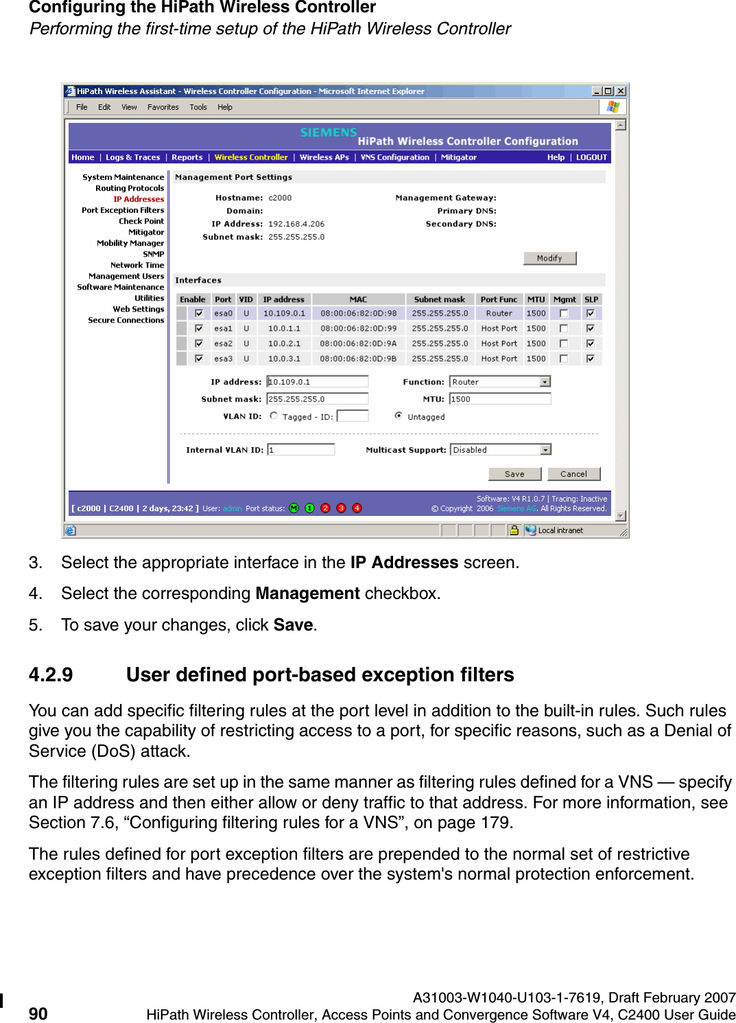
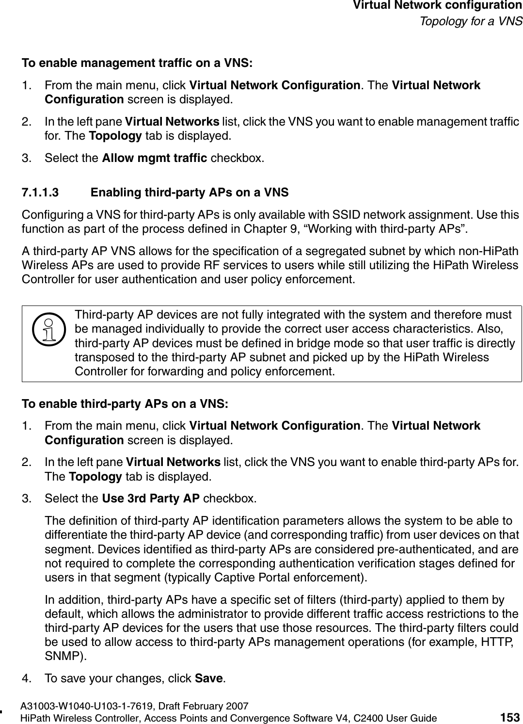
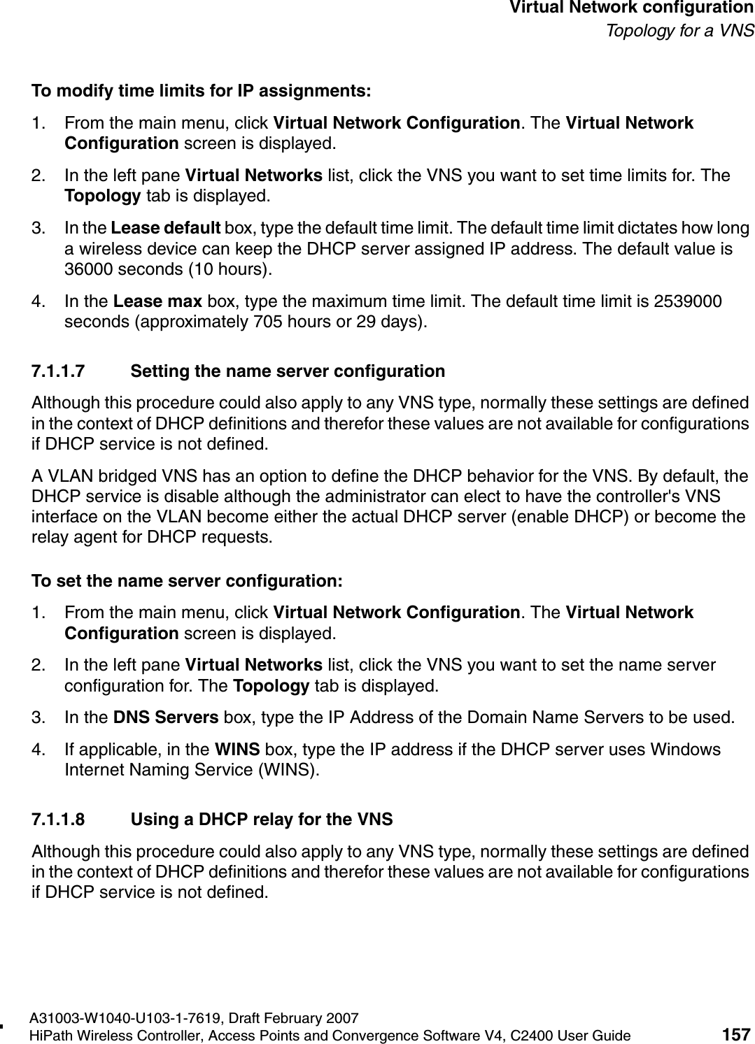
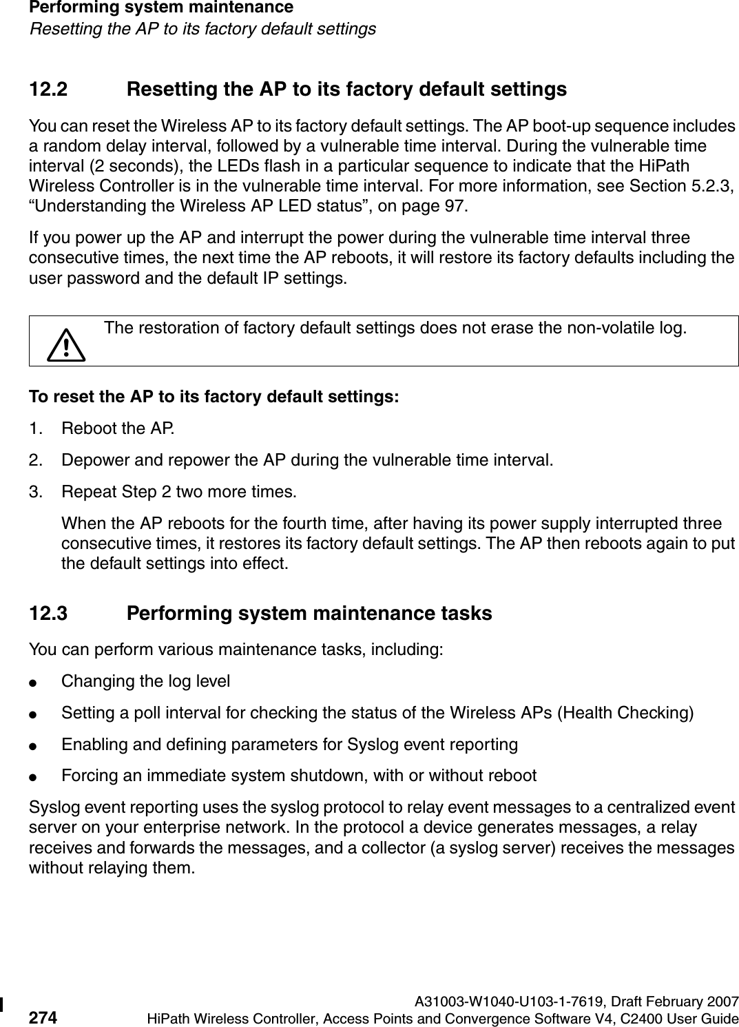
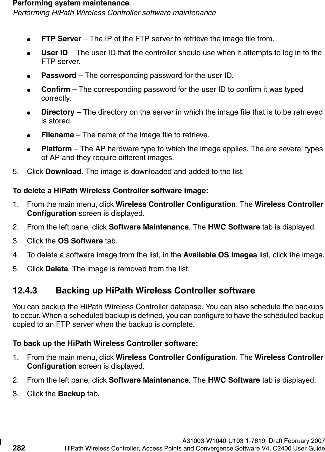
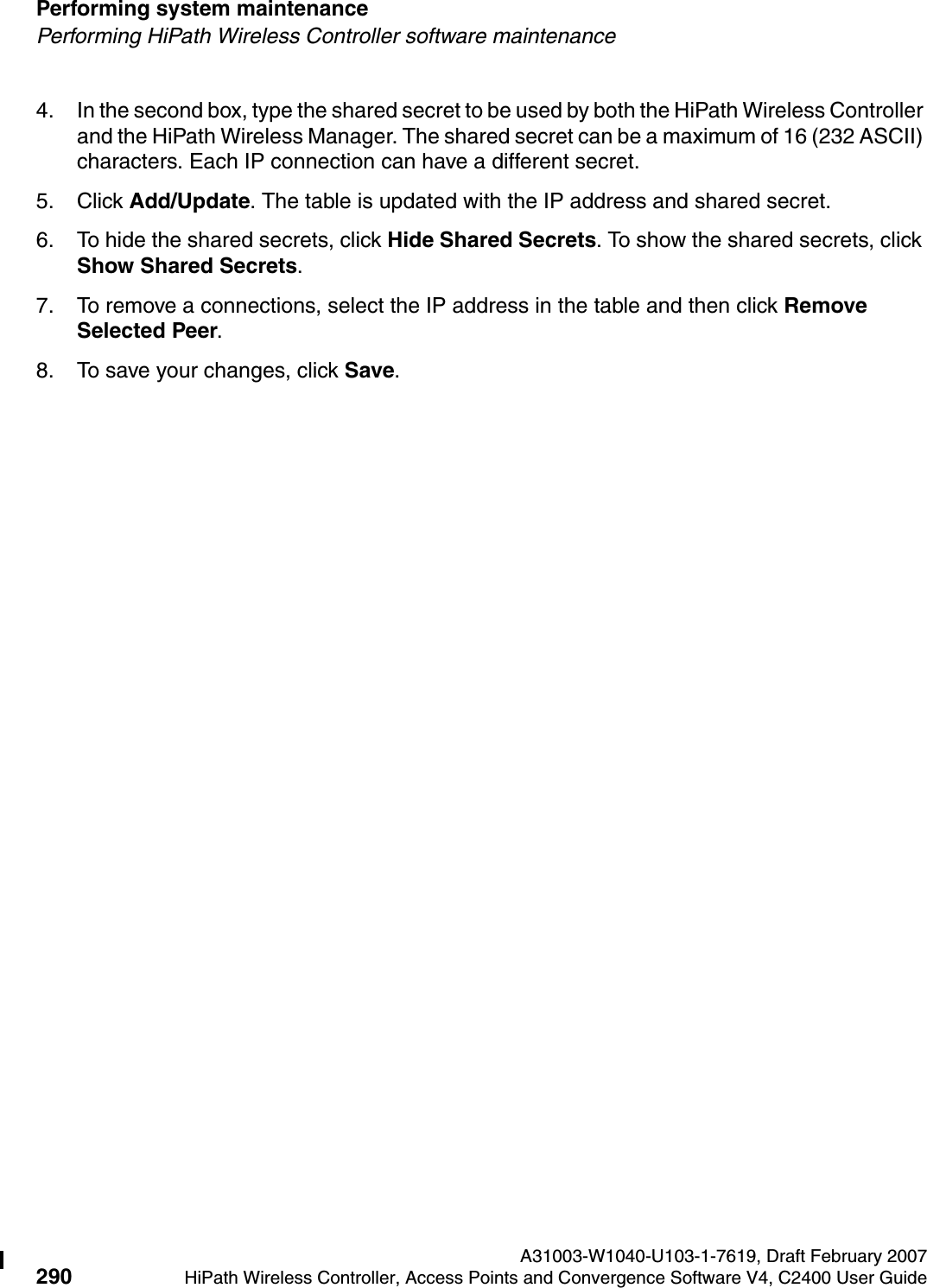
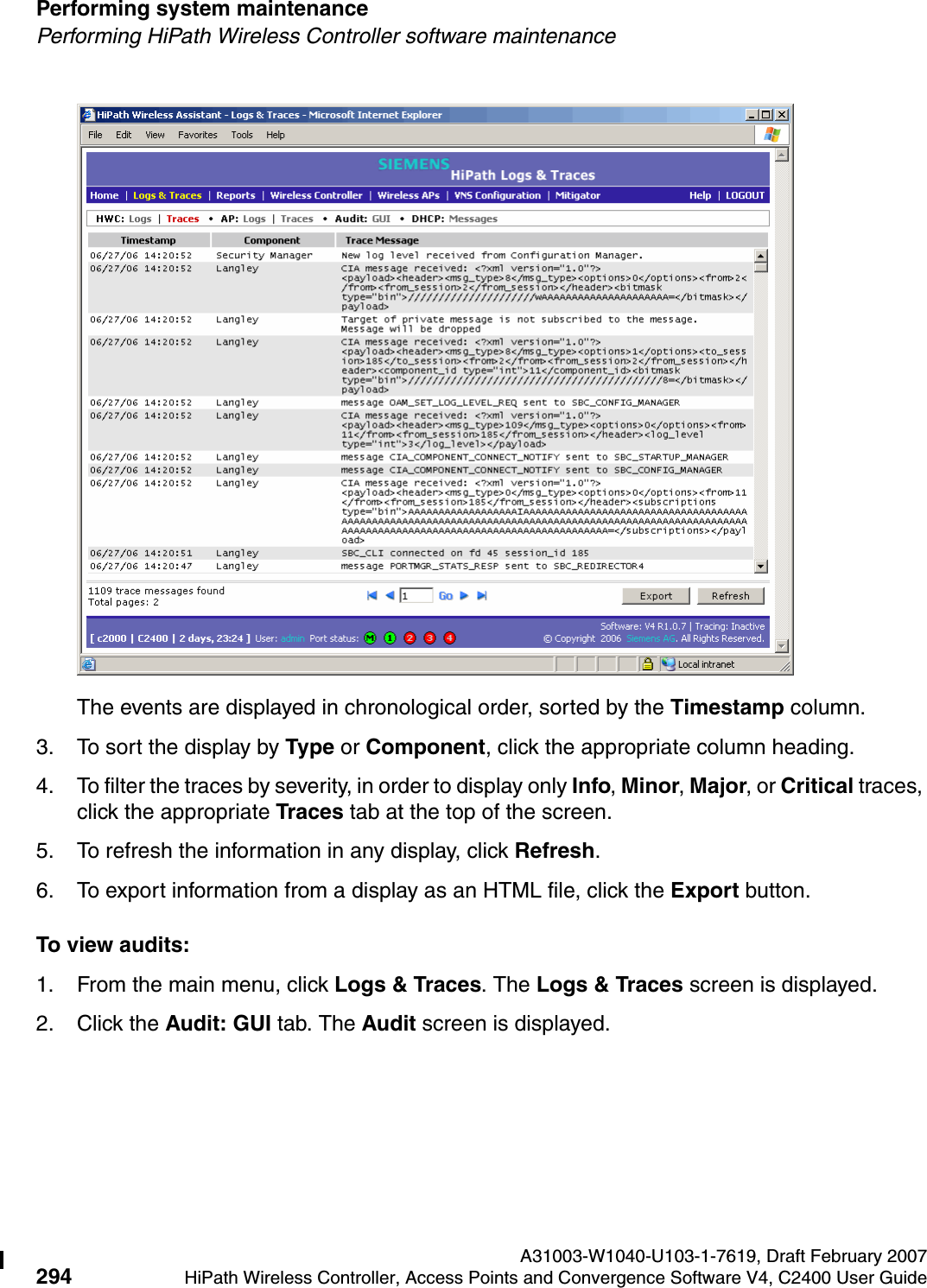
![hwc_startup.fmA31003-W1040-U103-1-7619, Draft February 2007HiPath Wireless Controller, Access Points and Convergence Software V4, C2400 User Guide 89 Configuring the HiPath Wireless ControllerPerforming the first-time setup of the HiPath Wireless ControllerFor example, on the HiPath Wireless Controller’s data interfaces (both physical interfaces and VNS virtual interfaces), the built-in exception filter prohibits invoking SSH, HTTPS, or SNMP. However, such traffic is allowed, by default, on the management port.If management traffic is explicitly enabled for any interface (physical port or VNS), access is implicitly extended to that interface through any of the other interfaces (VNS). Only traffic specifically allowed by the interface’s exception filter is allowed to reach the HiPath Wireless Controller itself. All other traffic is dropped. Exception filters are dynamically configured and regenerated whenever the system's interface topology changes (for example, a change of IP address for any interface). Enabling management traffic on an interface adds additional rules to the exception filter, which opens up the well-known IP(TCP/UDP) ports, corresponding to the HTTPS, SSH, and SNMP applications.The port-based built-in exception filtering rules, in the case of traffic from VNS users, are applicable to traffic targeted directly for the VNSs interface. For example, a VNS filter may be generic enough to allow traffic access to the HiPath Wireless Controller's management (for example, Allow All [*.*.*.*]). Exception filter rules are evaluated after the user's VNS assigned filter policy, as such, it is possible that the VNS policy allow the access to management functions that the exception filter denies. These packets are dropped. To enable SSH, HTTPS, or SNMP access through a data interface:1. From the main menu, click Wireless Controller Configuration. The HiPath Wireless Controller Configuration screen is displayed.2. In the left pane, click IP Addresses. The Management Port Settings screen is displayed.](https://usermanual.wiki/Chantry-Networks/APXXX1.USERS-MANUAL-1/User-Guide-755957-Page-89.png)

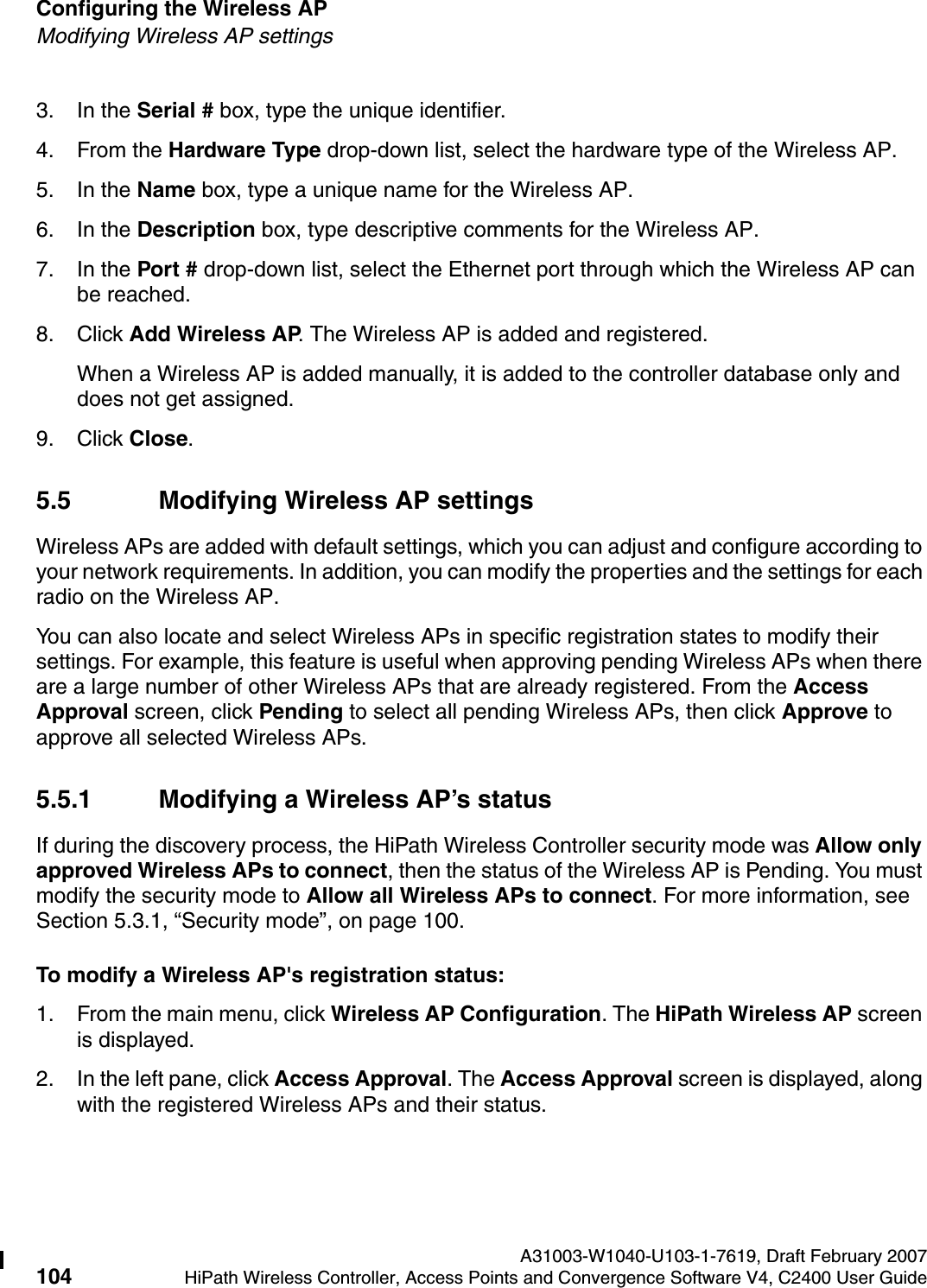
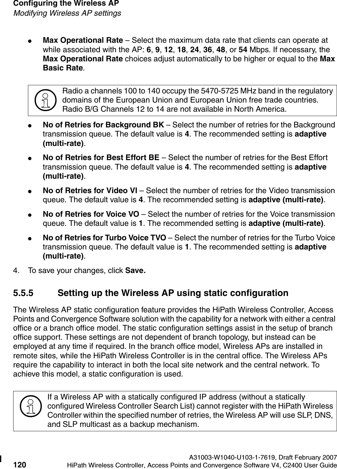
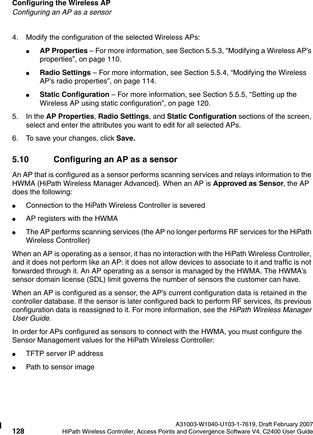
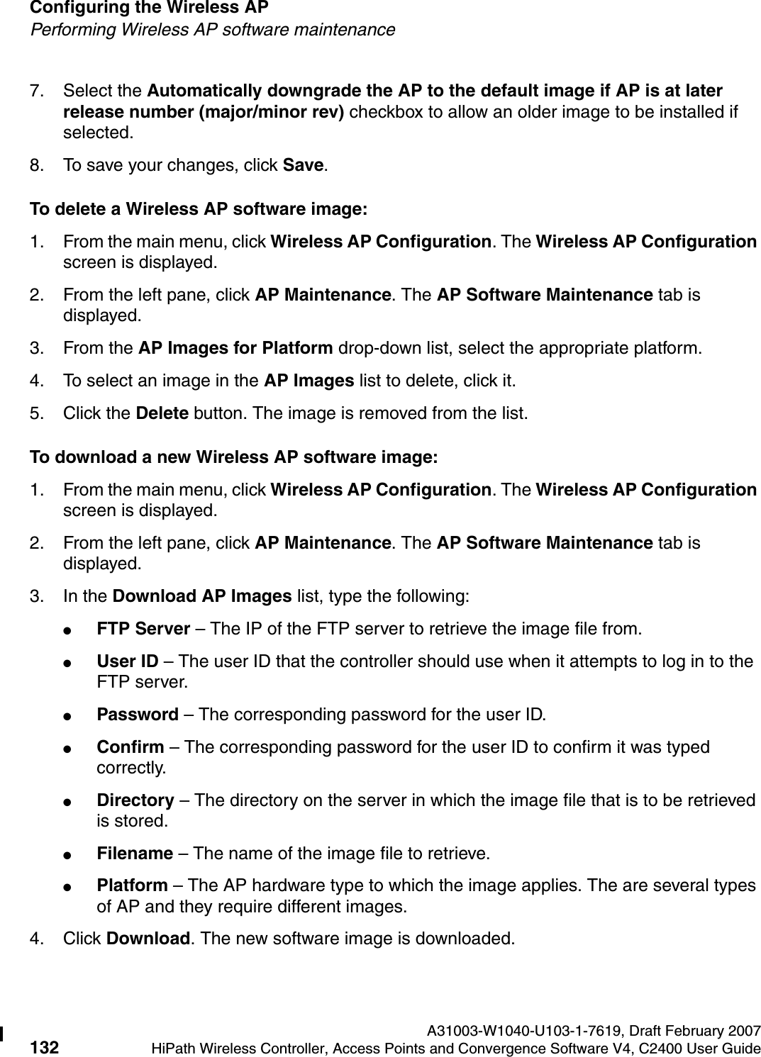

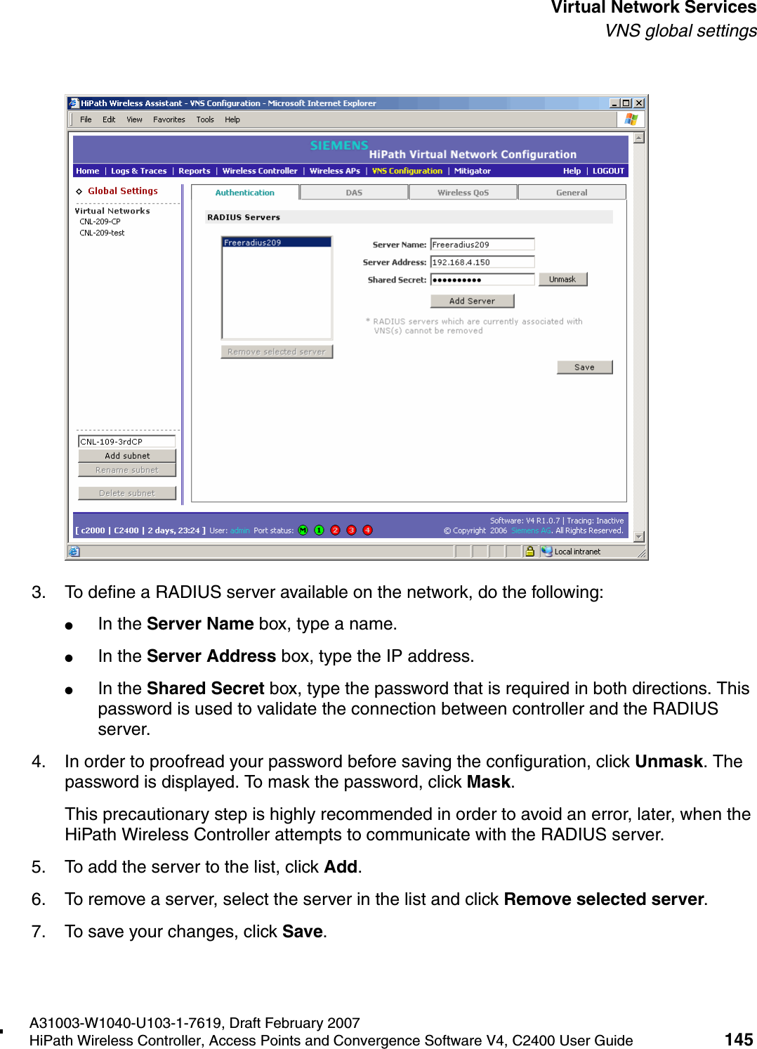
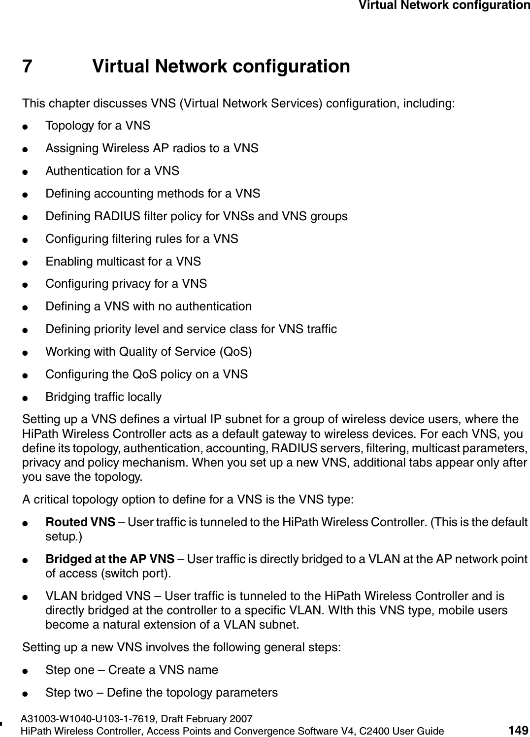
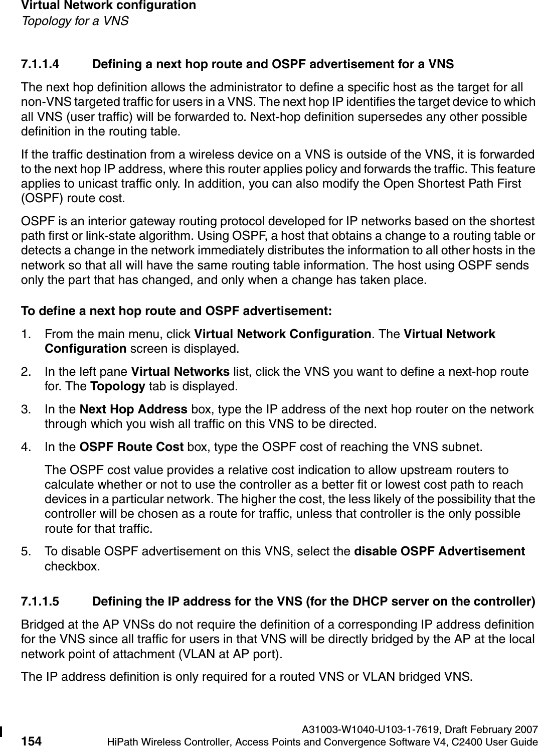
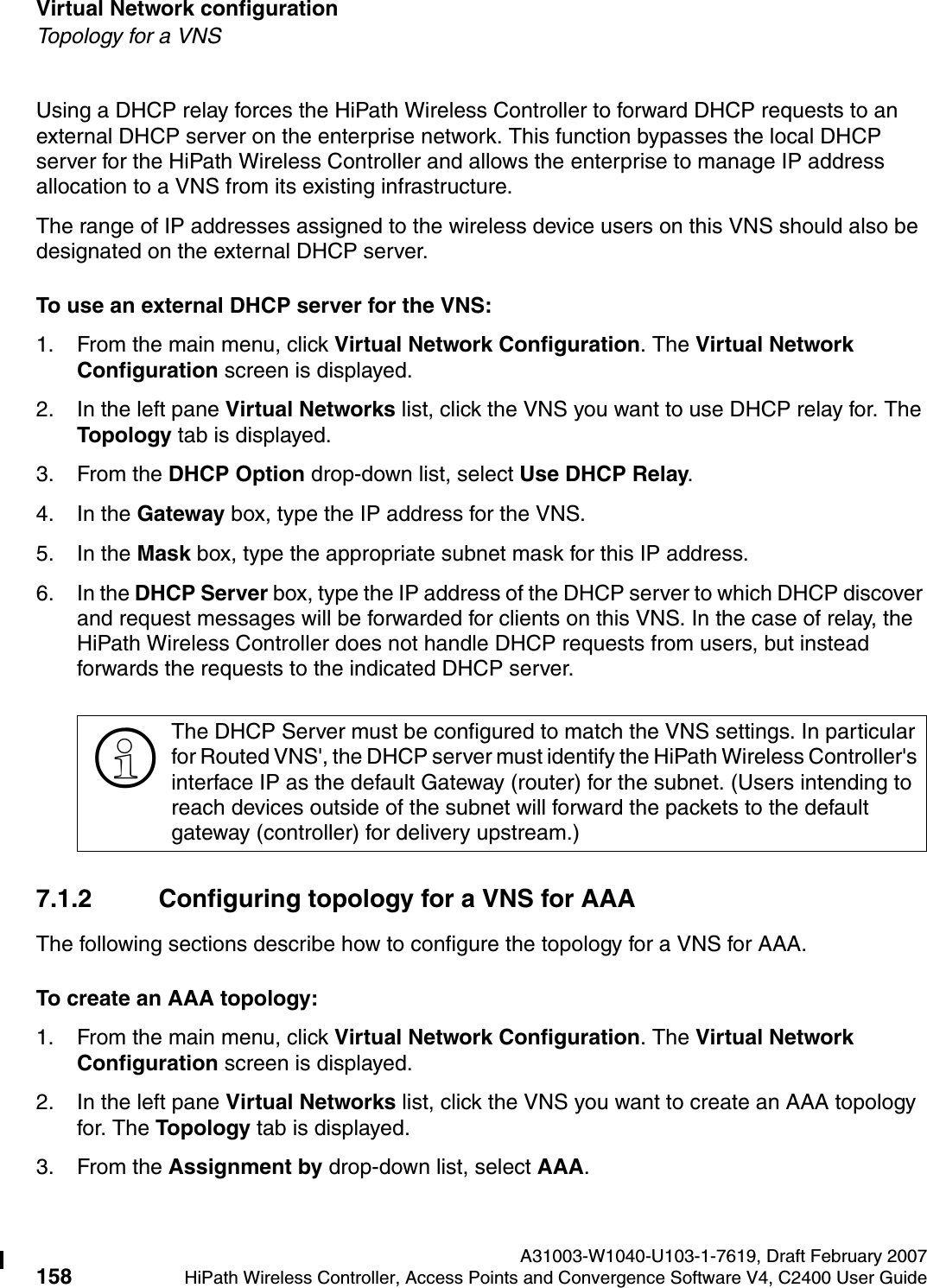

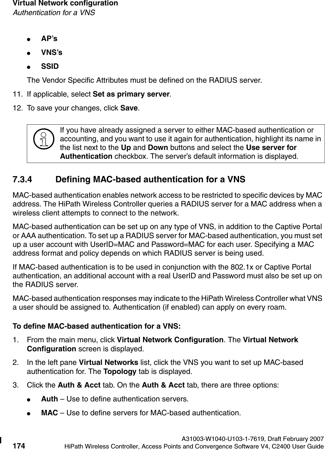
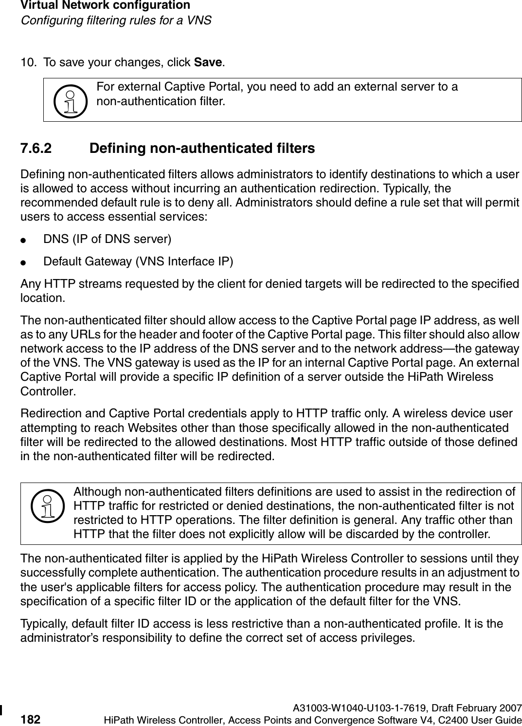
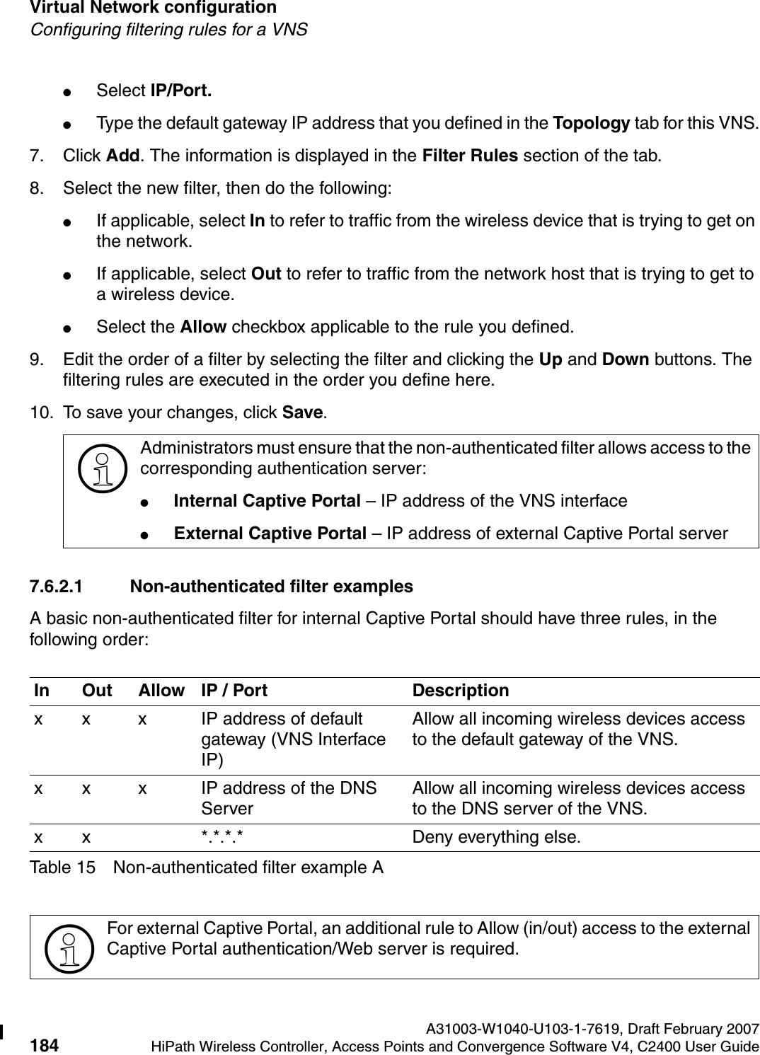
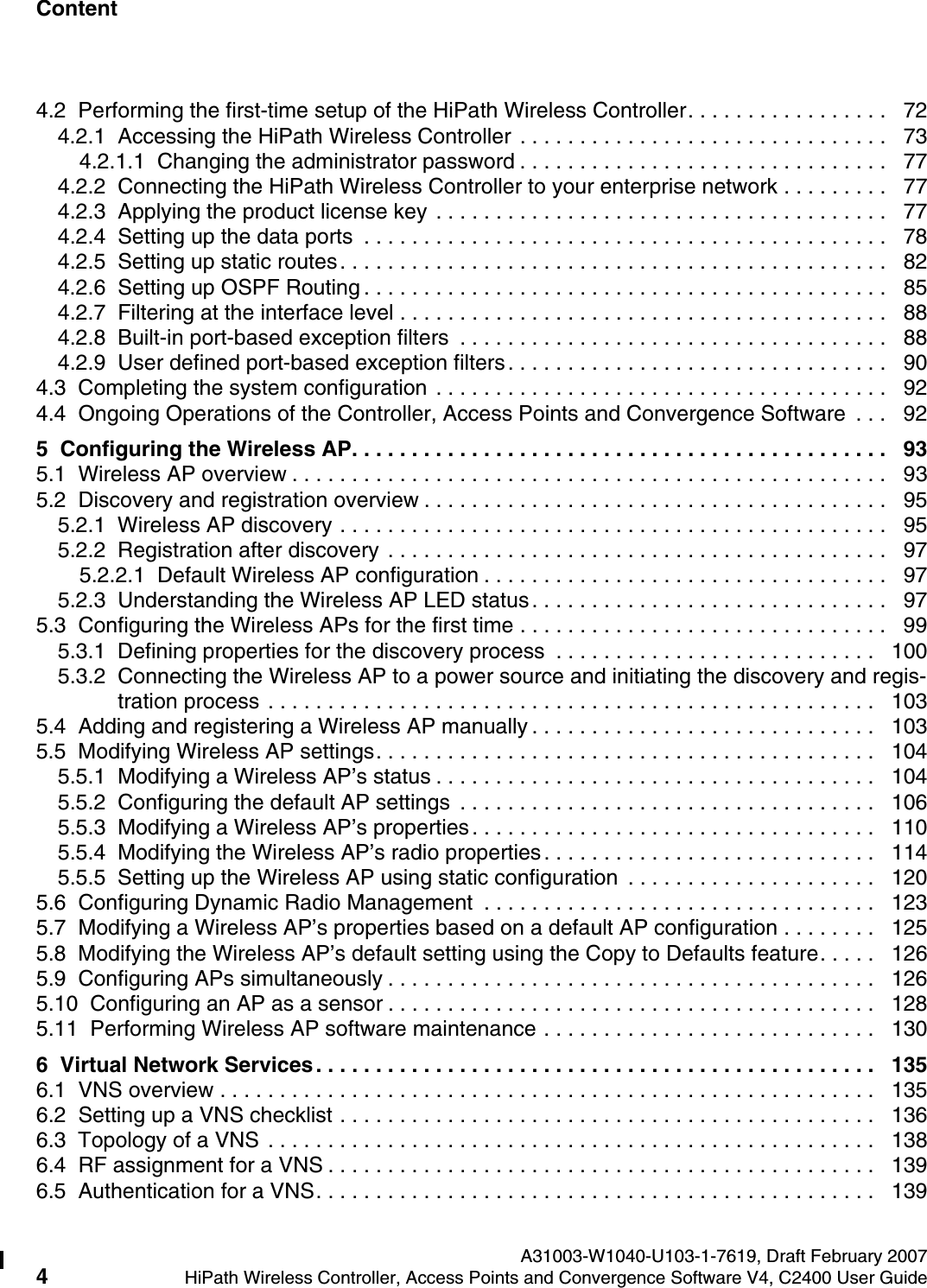
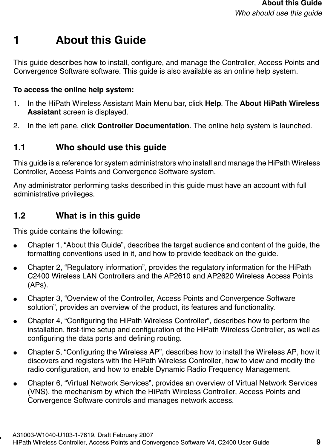
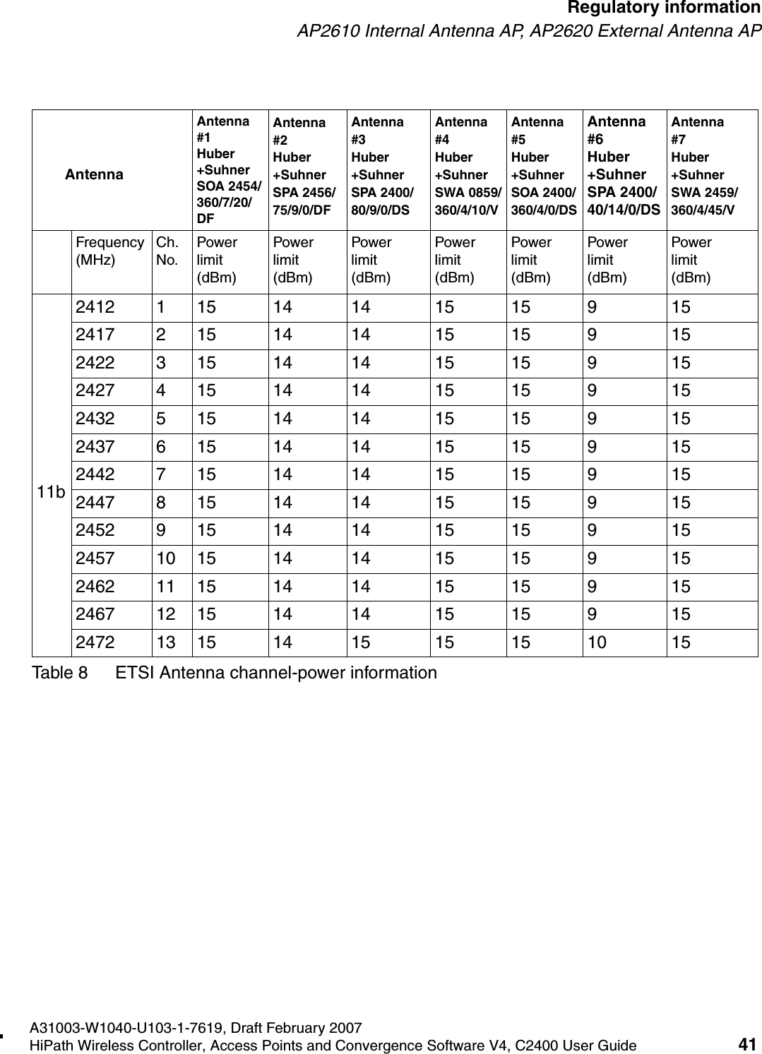
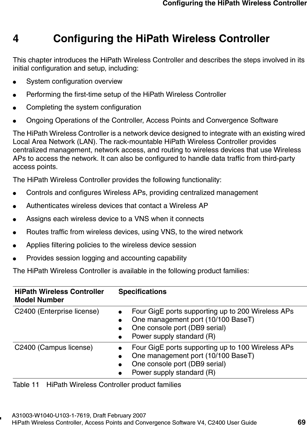
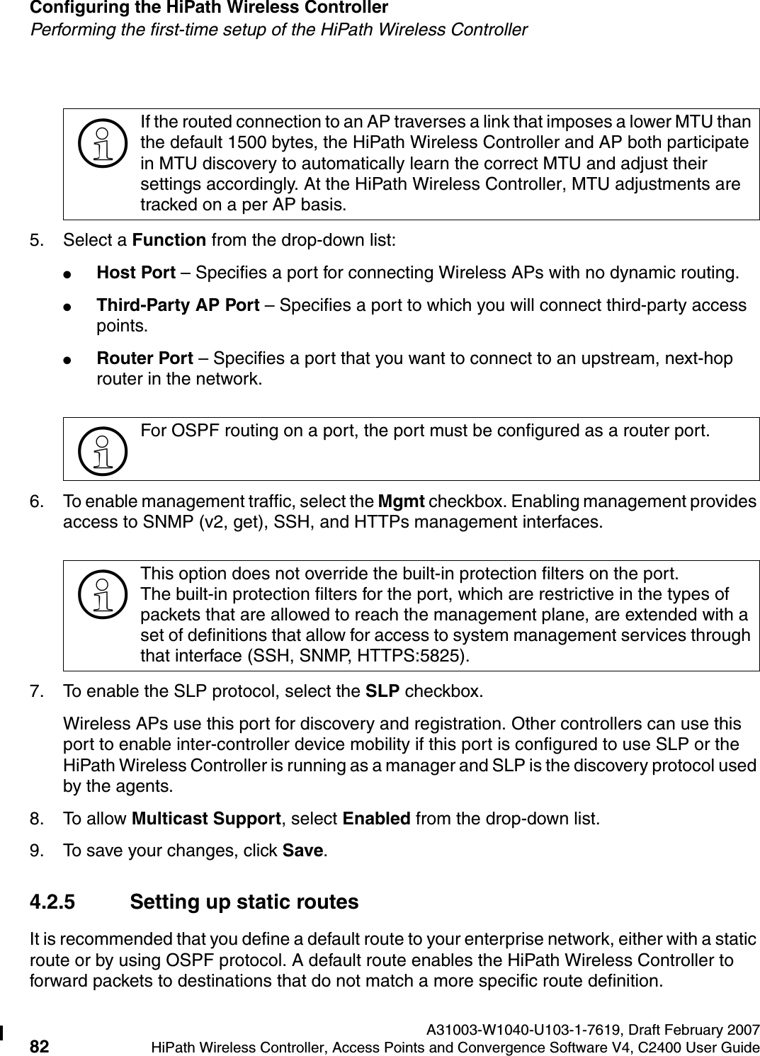
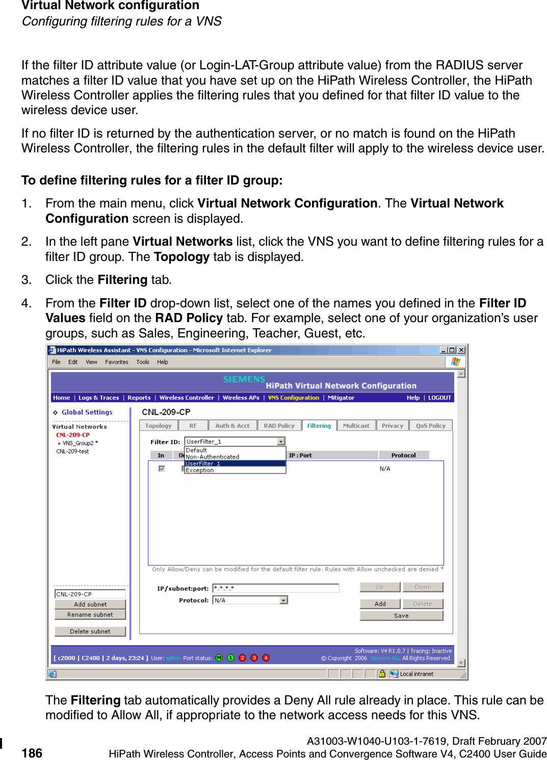
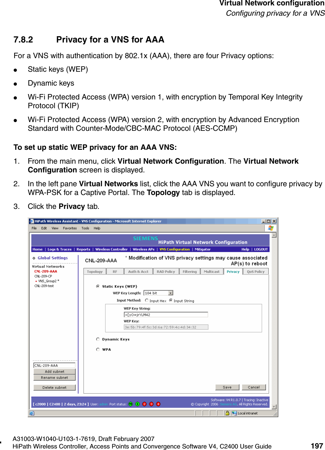
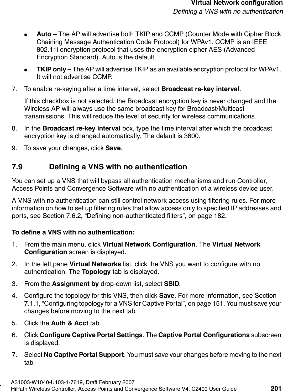
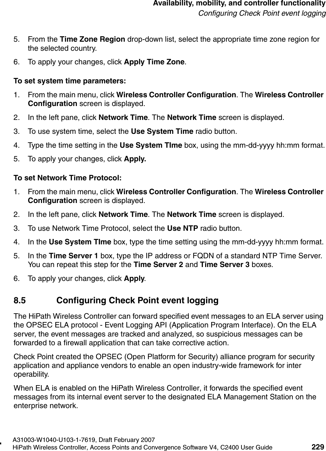
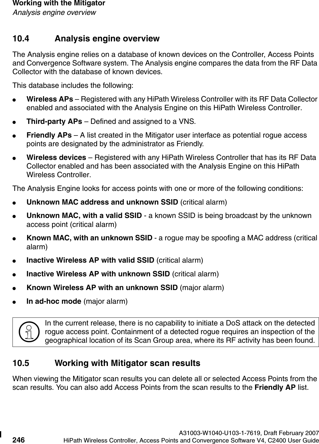
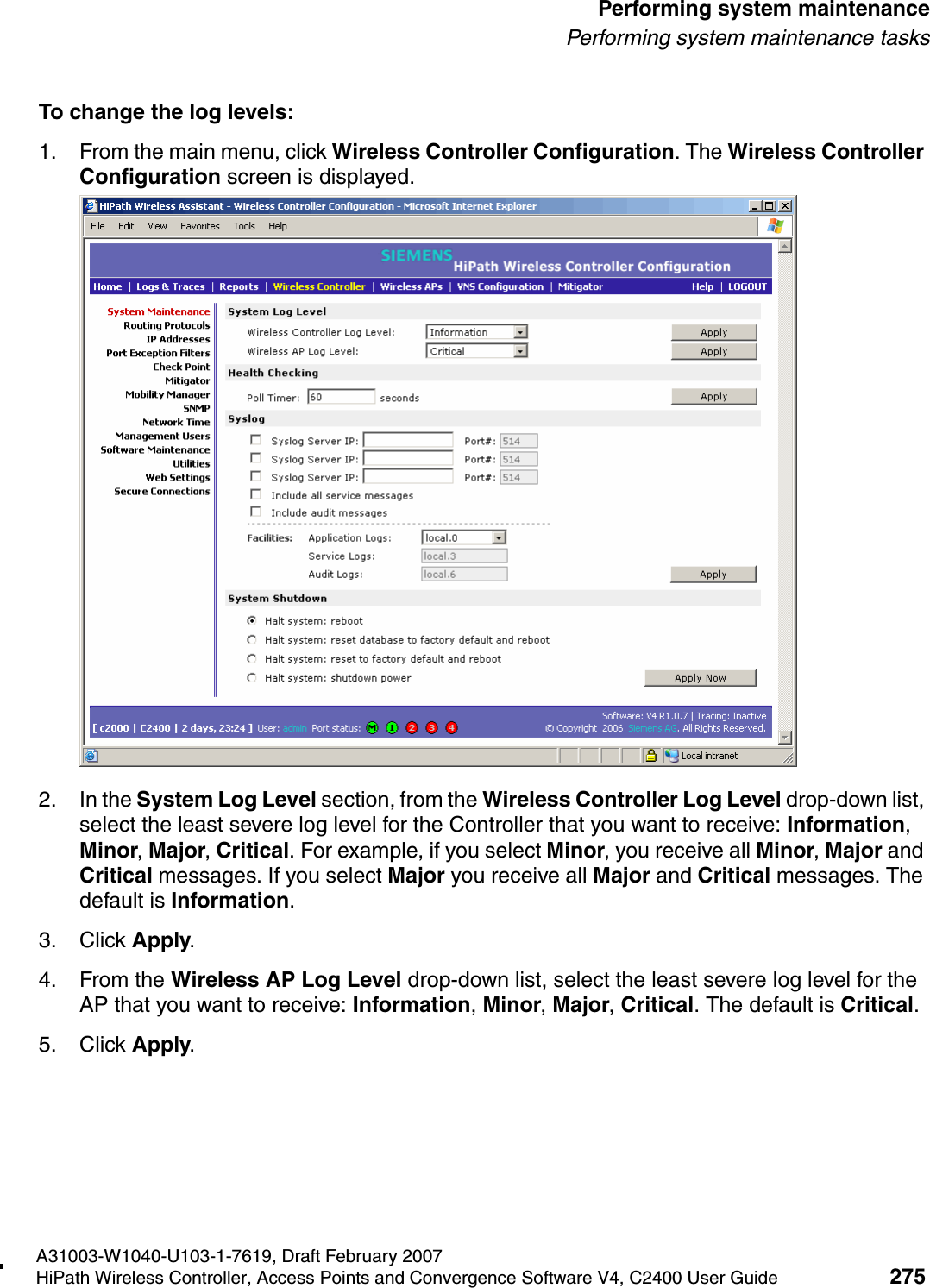
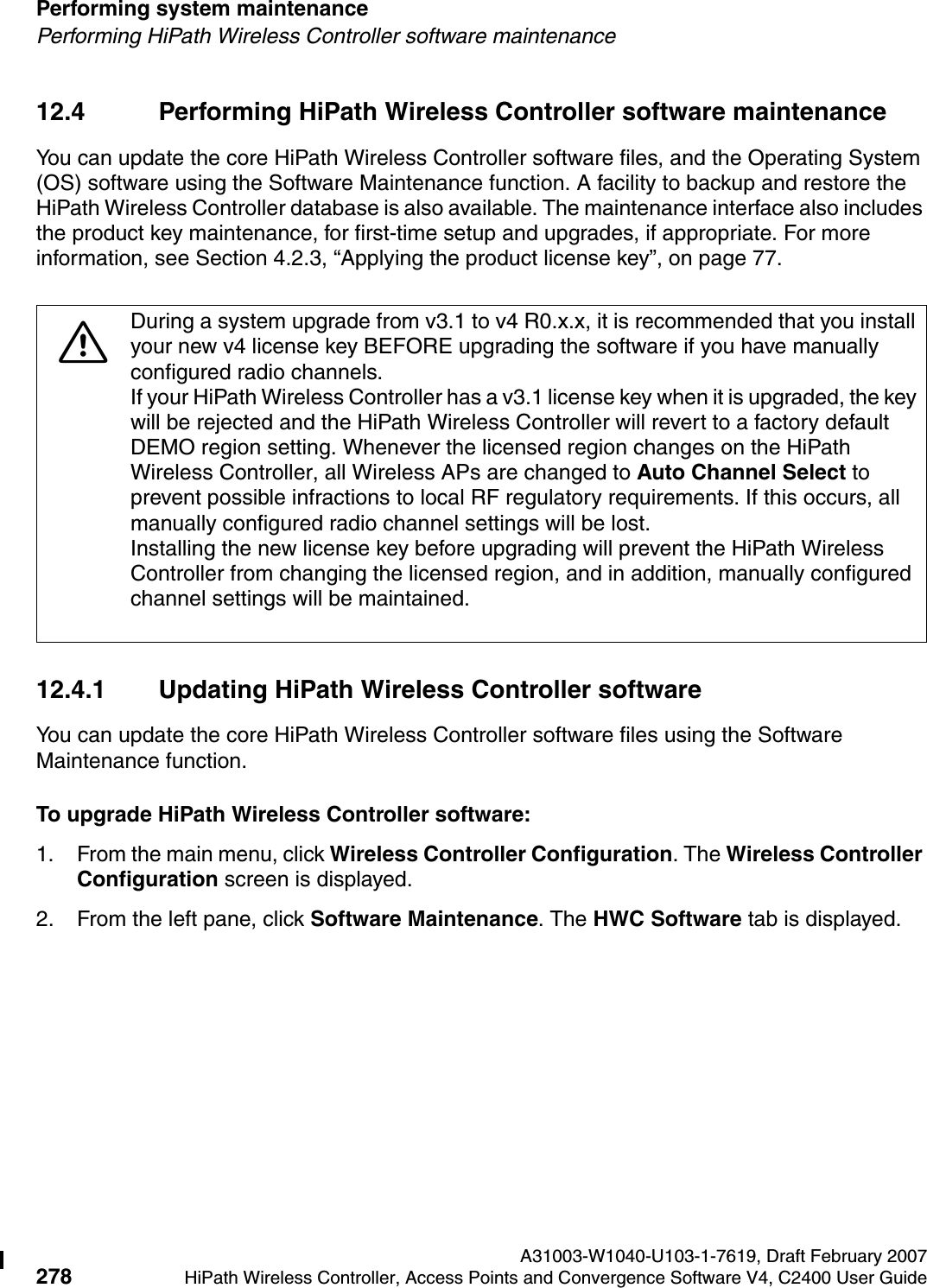
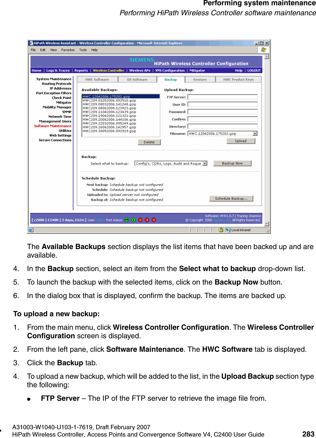
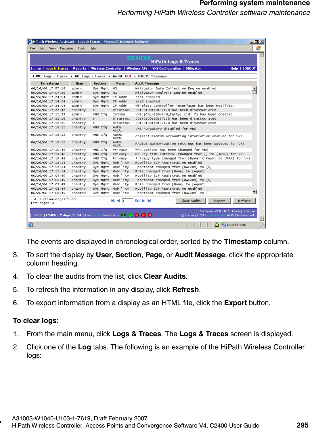
![hwc_vnsconfiguration.fmA31003-W1040-U103-1-7619, Draft February 2007HiPath Wireless Controller, Access Points and Convergence Software V4, C2400 User Guide 185 Virtual Network configurationConfiguring filtering rules for a VNSIf you place URLs in the header and footer of the Captive Portal page, you must explicitly allow access to any URLs mentioned in the authentication's server page, such as:●Internal Captive Portal – URLs referenced in a header or footer●External Captive Portal – URLs mentioned in the page definitionHere is another example of a non-authenticated filter that adds two more filtering rules. The two additional rules do the following: ●Deny access to a specific IP address.●Allows only HTTP traffic.Once a wireless device user has logged in on the Captive Portal page, and has been authenticated by the RADIUS server, then the following filters will apply:●Filter ID – If a filter ID associated with this user was returned by the authentication server.●Default filter – If no matching filter ID was returned from the authentication server7.6.3 Filtering rules for a filter ID groupWhen the wireless device user provides the identification credentials, identification is sent by the HiPath Wireless Controller to the RADIUS server, or other authentication server, through a sequence of exchanges depending on the type of authentication protocol used. When the server allows this request for authentication—the server sends an access-accept message, the RADIUS server may also send back to the HiPath Wireless Controller a filter ID attribute value associated with the user. For an AAA VNS, a Login-LAT-Group identifier for the user may also be returned. VNS Policy is also applicable for Captive Portal and MAC-based authorization.In Out Allow IP / Port Descriptionx x x IP address of the default gatewayAllow all incoming wireless devices access to the default gateway of the VNS.x x x IP address of the DNS ServerAllow all incoming wireless devices access to the DNS server of the VNS.x x [a specific IP address, or address plus range]Deny all traffic to a specific IP address, or to a specific IP address range (such as:0/24).x x *.*.*.*:80 Deny all port 80 (HTTP) traffic.x x *.*.*.* Deny everything else. Table 16 Non-authenticated filter example B](https://usermanual.wiki/Chantry-Networks/APXXX1.USERS-MANUAL-1/User-Guide-755957-Page-185.png)
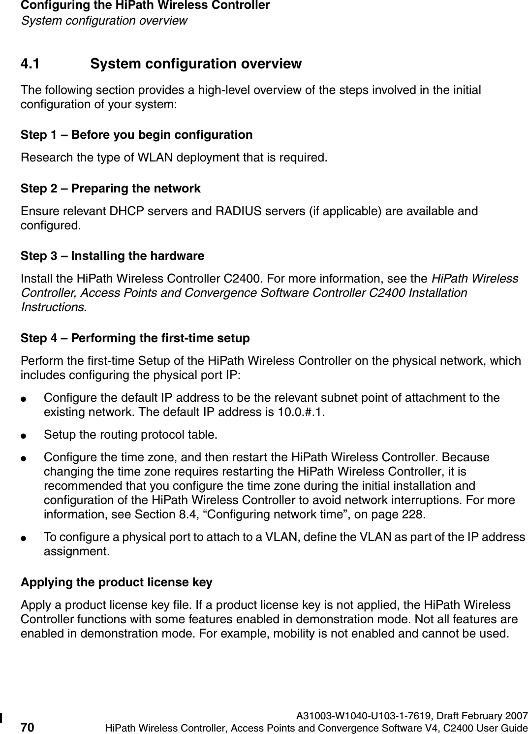
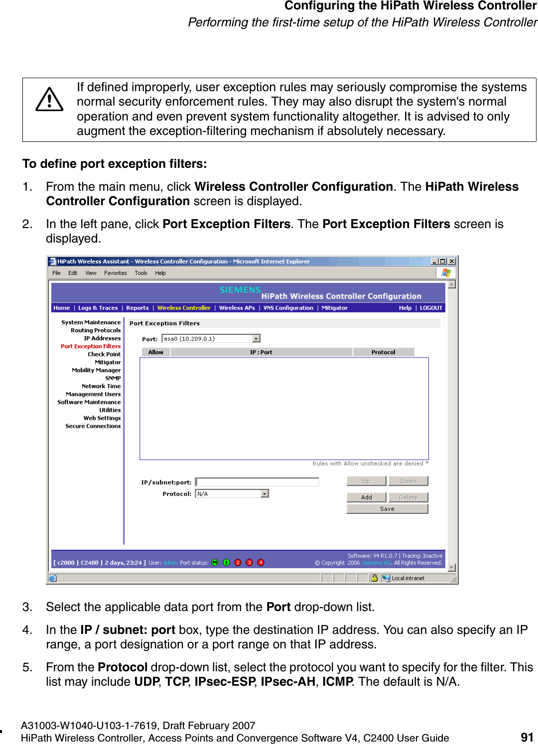
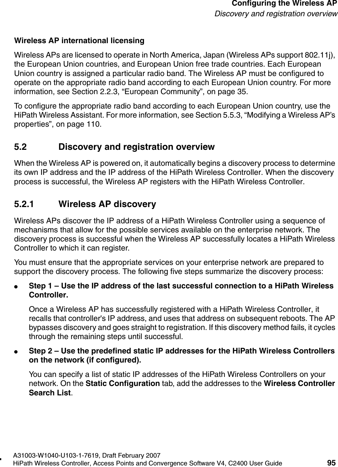
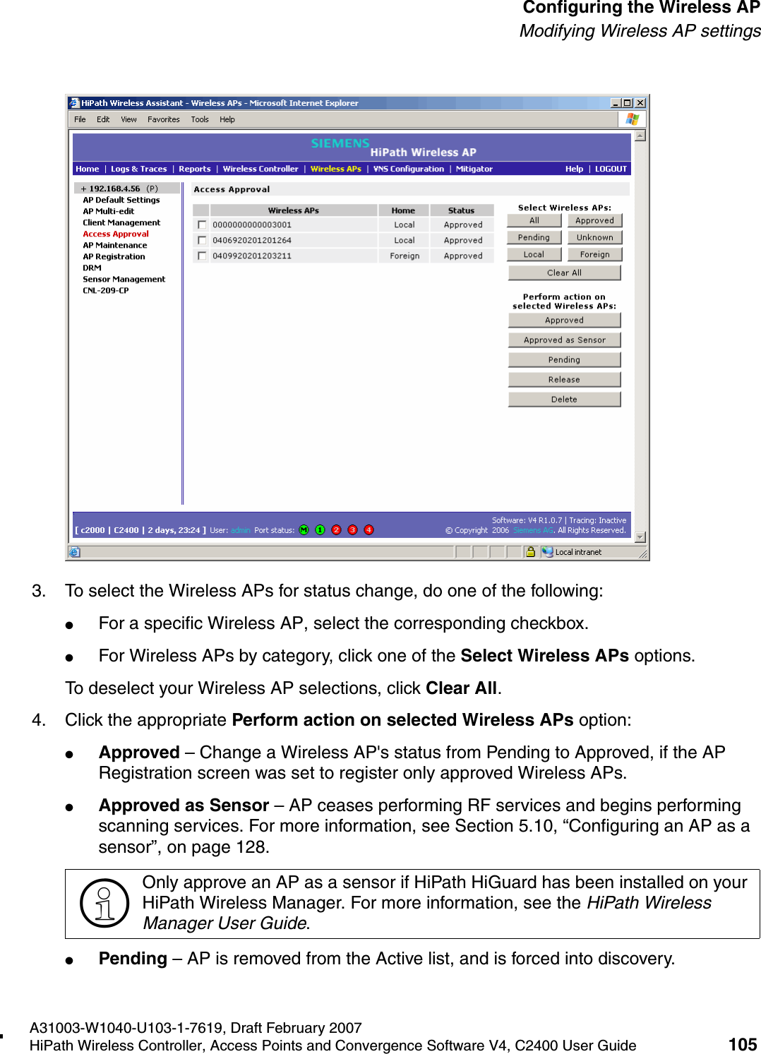
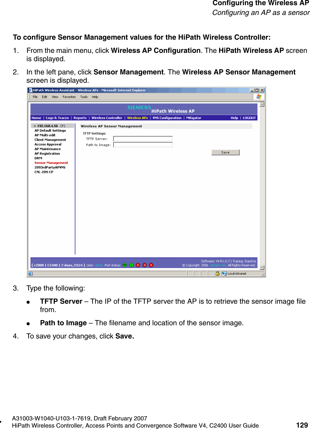
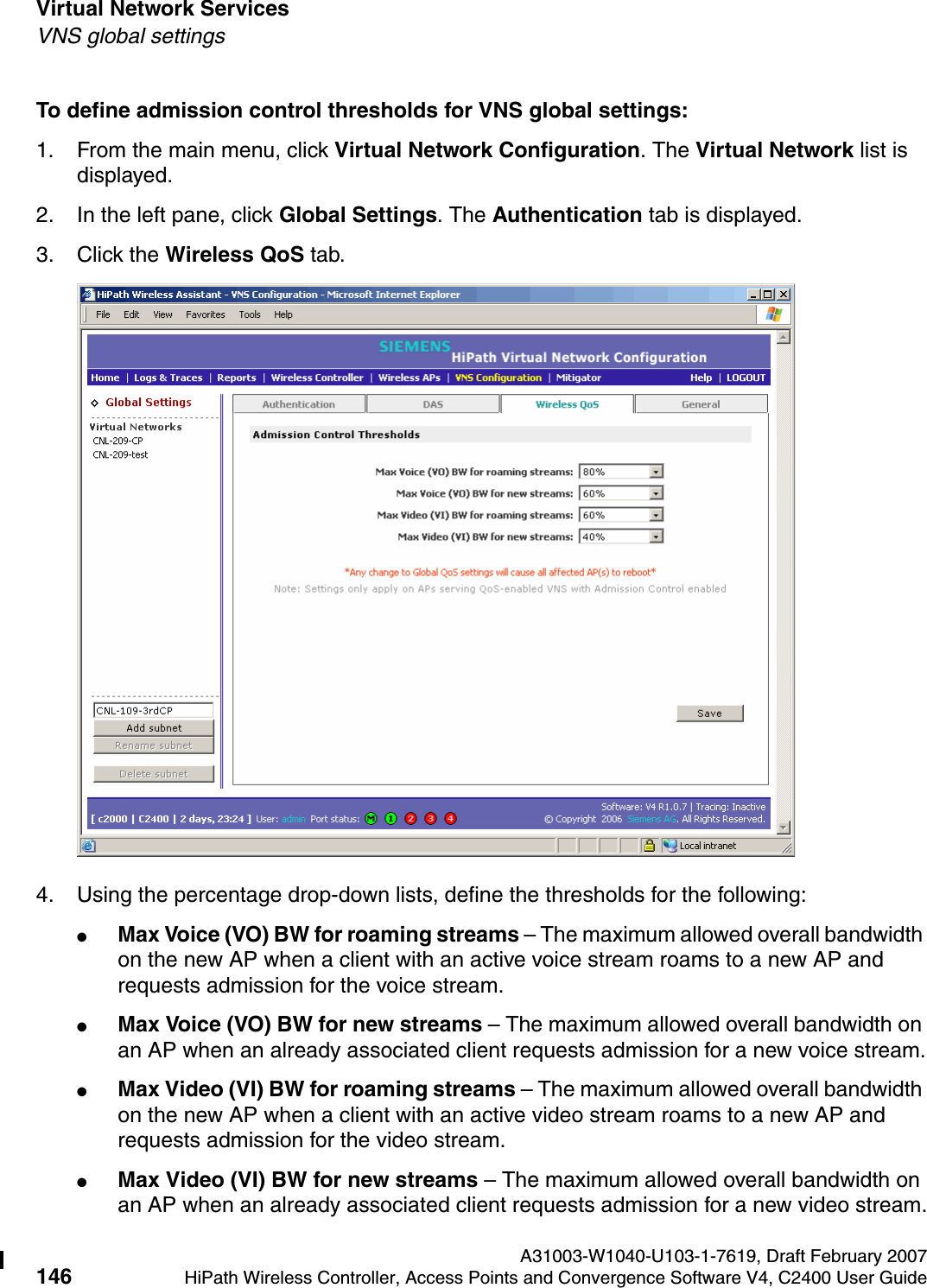
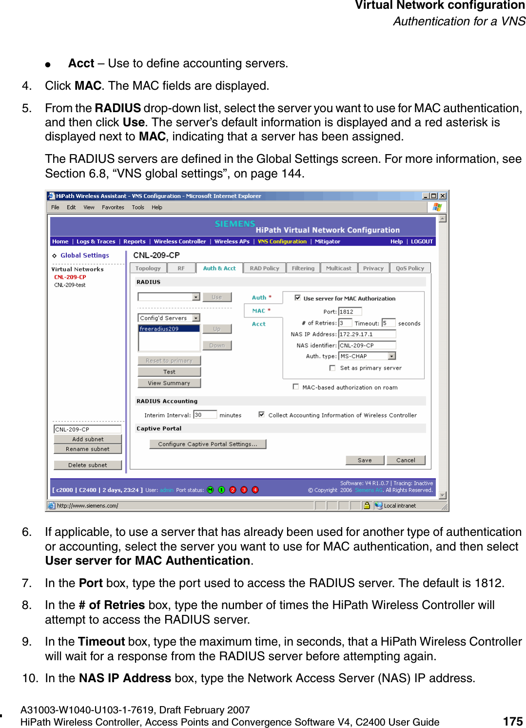
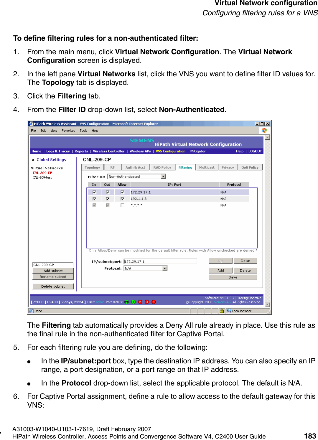
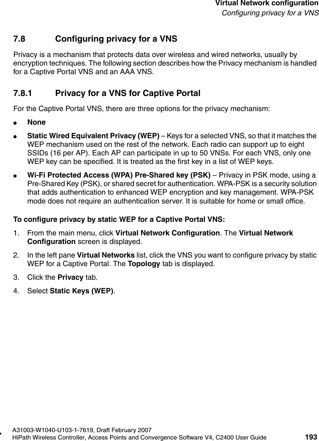
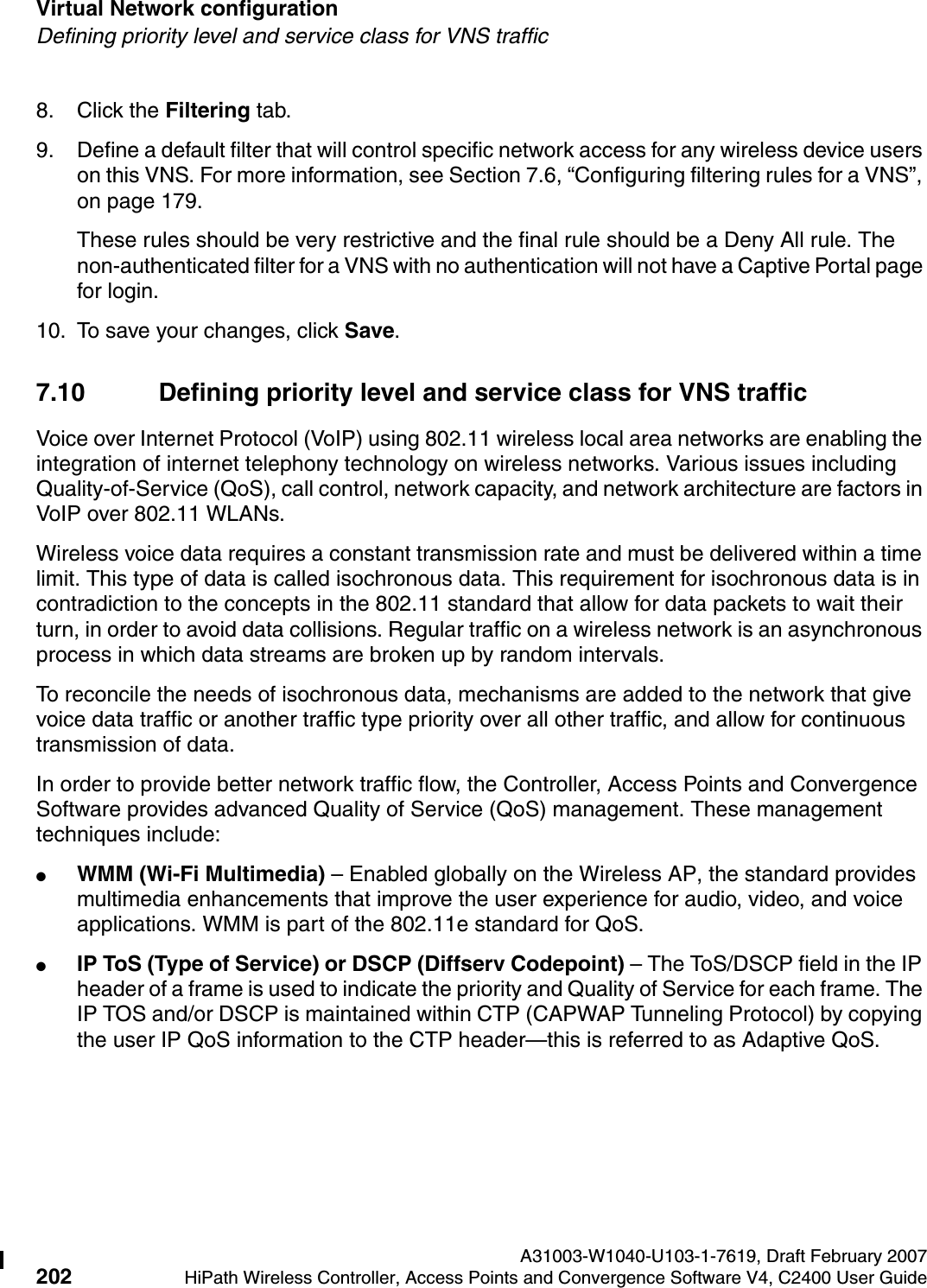
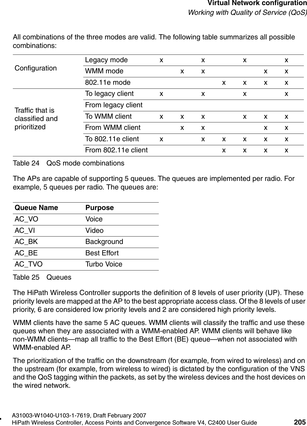
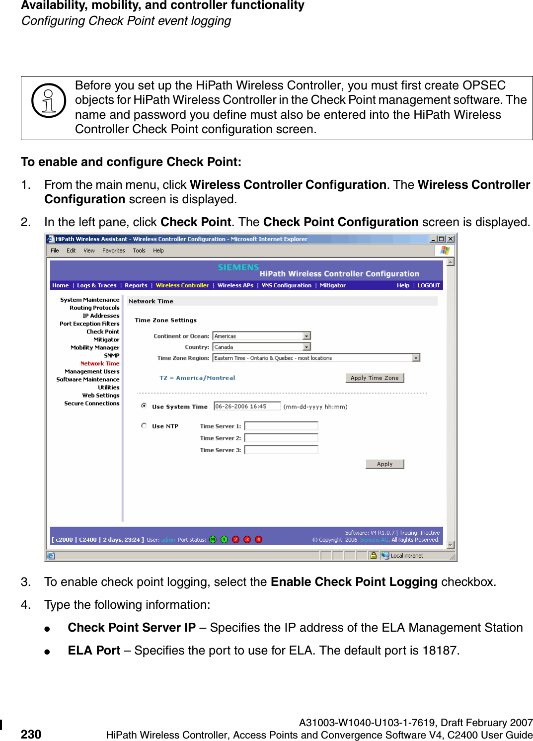
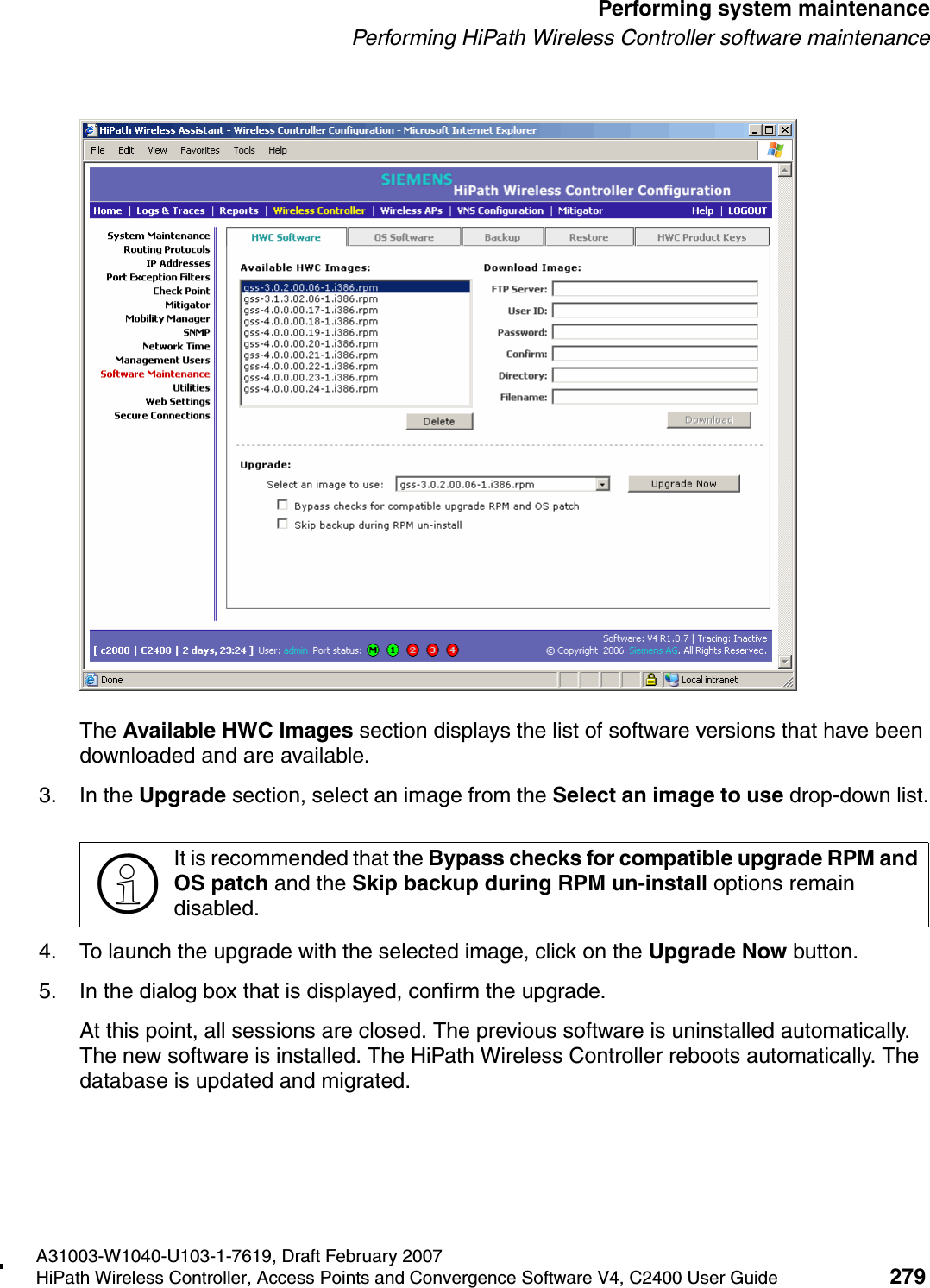
![hwc_vnsconfiguration.fmA31003-W1040-U103-1-7619, Draft February 2007HiPath Wireless Controller, Access Points and Convergence Software V4, C2400 User Guide 187 Virtual Network configurationConfiguring filtering rules for a VNS5. For each filtering rule you are defining, do the following:●In the IP/subnet:port box, type the destination IP address. You can also specify an IP range, a port designation, or a port range on that IP address.●In the Protocol drop-down list, select the applicable protocol. The default is N/A.6. Click Add. The information is displayed in the Filter Rules section of the tab.7. Select the new filter, then do the following:●If applicable, select In to refer to traffic from the wireless device that is trying to get on the network.●If applicable, select Out to refer to traffic from the network host that is trying to get to a wireless device. ●Select the Allow checkbox applicable to the rule you defined.8. Edit the order of a filter by selecting the filter and clicking the Up and Down buttons. The filtering rules are executed in the order you define here.9. To save your changes, click Save.7.6.3.1 Filtering rules by filter ID examplesBelow are two examples of possible filtering rules for a filter ID. The first example disallows some specific access before allowing everything else.The second example does the opposite of the first example. It allows some specific access and denies everything else. In Out Allow IP / Port Descriptionx x *.*.*.*:22-23 SSH and telnet sessionsx x [specific IP address, range] Deny all traffic to a specific IP address or address rangex x x *.*.*.*. Allow everything elseTable 17 Filtering rules by filter ID example AIn Out Allow IP / Port Descriptionx x x [specific IP address, range] Allow traffic to a specific IP address or address range.x x *.*.*.*. Deny everything else.Table 18 Filtering rules by filter ID example B](https://usermanual.wiki/Chantry-Networks/APXXX1.USERS-MANUAL-1/User-Guide-755957-Page-187.png)
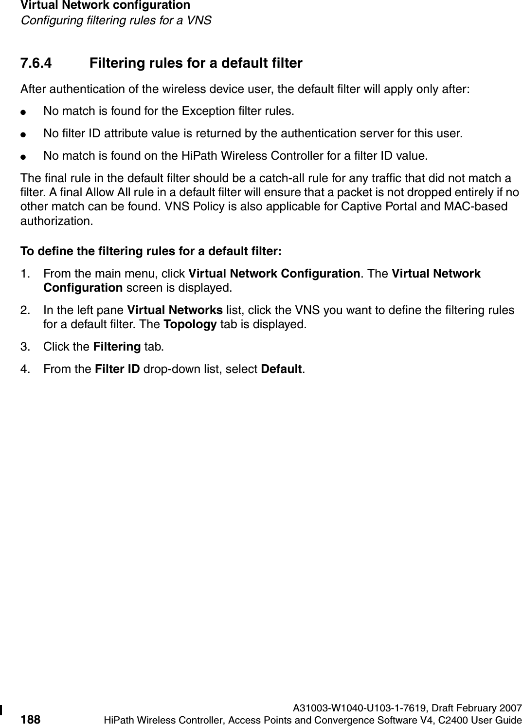
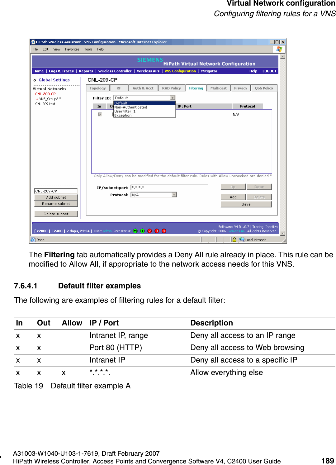
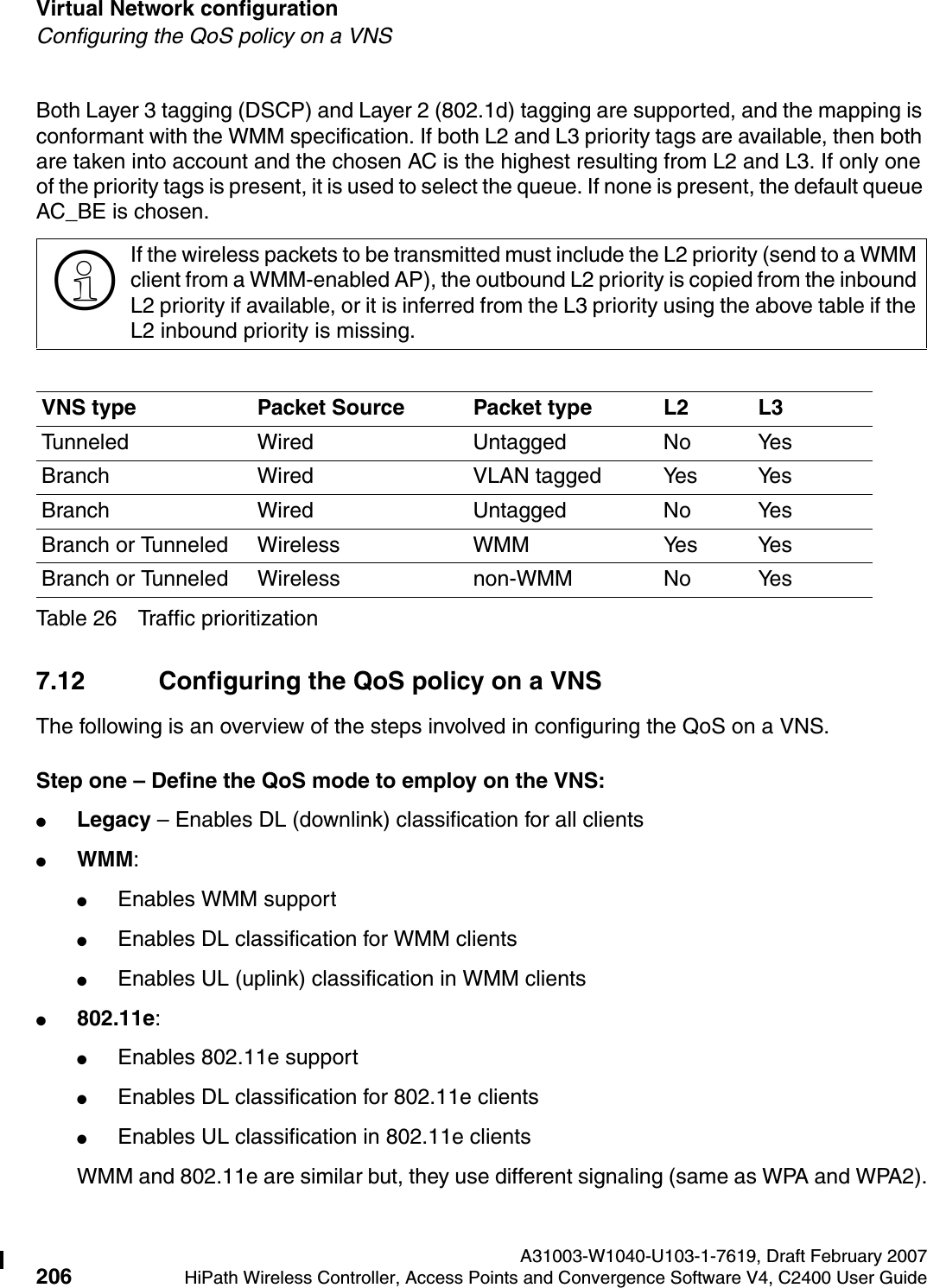
![Virtual Network configuration A31003-W1040-U103-1-7619, Draft February 2007190 HiPath Wireless Controller, Access Points and Convergence Software V4, C2400 User Guide hwc_vnsconfiguration.fmConfiguring filtering rules for a VNS7.6.4.2 Filtering rules for an AAA child group VNSIf you defined a child group for an AAA VNS, it will have the same authentication parameters and filter IDs as the parent VNS. However, you can define different filtering rules for the filters IDs in the child configuration from those in the parent configuration.7.6.4.3 Filtering rules between two wireless devicesTraffic from two wireless devices that are on the same VNS and are connected to the same Wireless AP will pass through the HiPath Wireless Controller and therefore be subject to filtering policy. You can set up filtering rules that allow each wireless device access to the default gateway, but also prevent each device from communicating with each other. Add the following two rules to a filter ID filter, before allowing everything else:In Out Allow IP / Port Descriptionx Port 80 (HTTP) on host IP Deny all incoming wireless devices access to Web browsing the hostx Intranet IP 10.3.0.20, ports 10-30Deny all traffic from the network to the wireless devices on the port range, such as TELNET (port 23) or FTP (port 21)x x Intranet IP 10.3.0.20 Allow all other traffic from the wireless devices to the Intranet networkx x Intranet IP 10.3.0.20 Allow all other traffic from Intranet network to wireless devicesx x x *.*.*.*. Allow everything elseTable 20 Default filter example BIn Out Allow IP / Port Descriptionx x x [Intranet IP] Allow access to the Gateway IP address of the VNS onlyx x [Intranet IP, range] Deny all access to the VNS subnet range (such as 0/24)x x x *.*.*.*. Allow everything elseTable 21 Rules between two wireless devices](https://usermanual.wiki/Chantry-Networks/APXXX1.USERS-MANUAL-1/User-Guide-755957-Page-190.png)

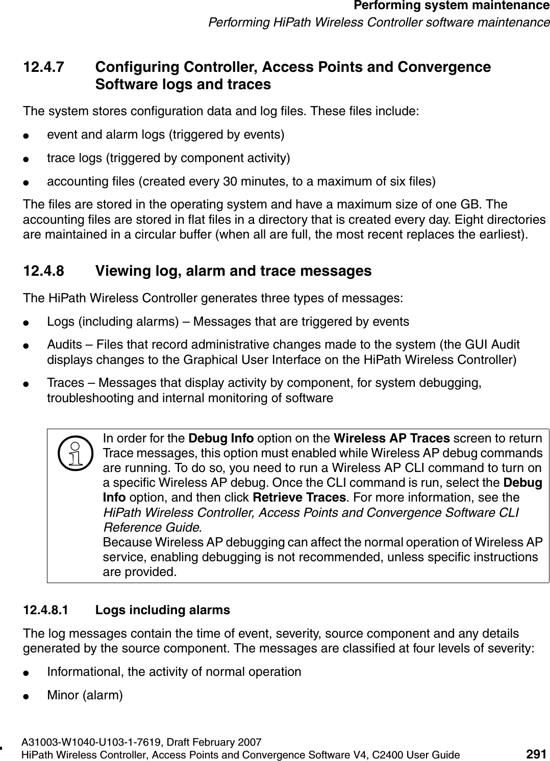
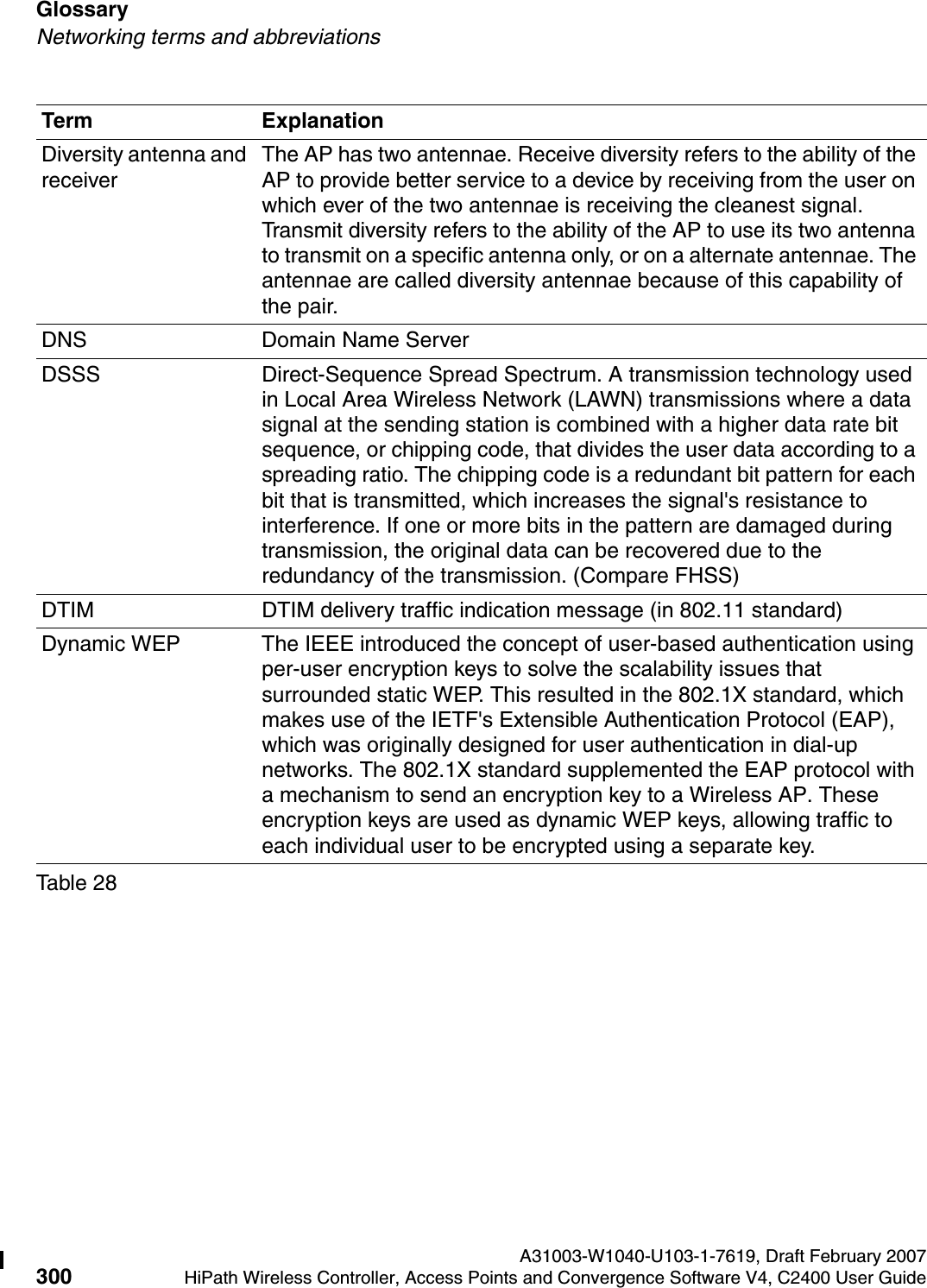
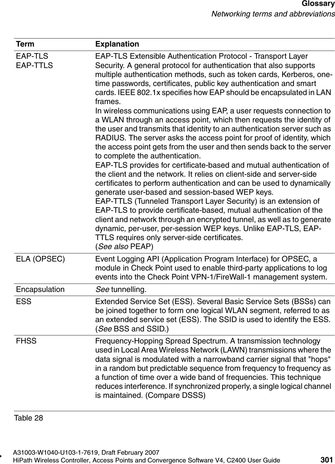
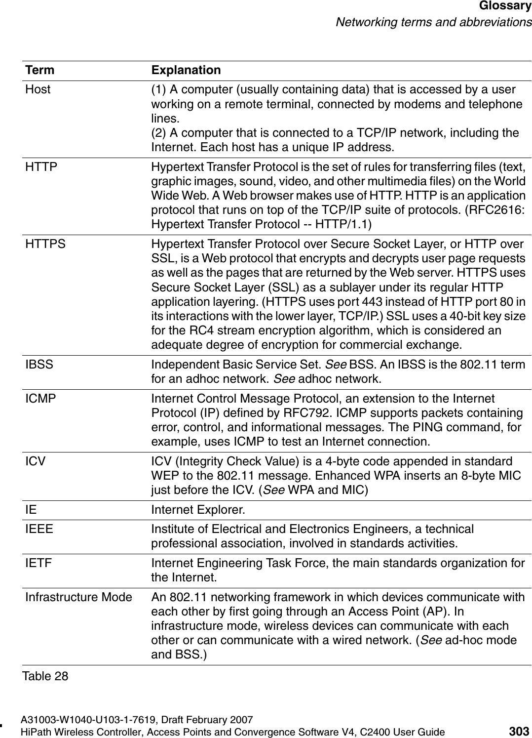
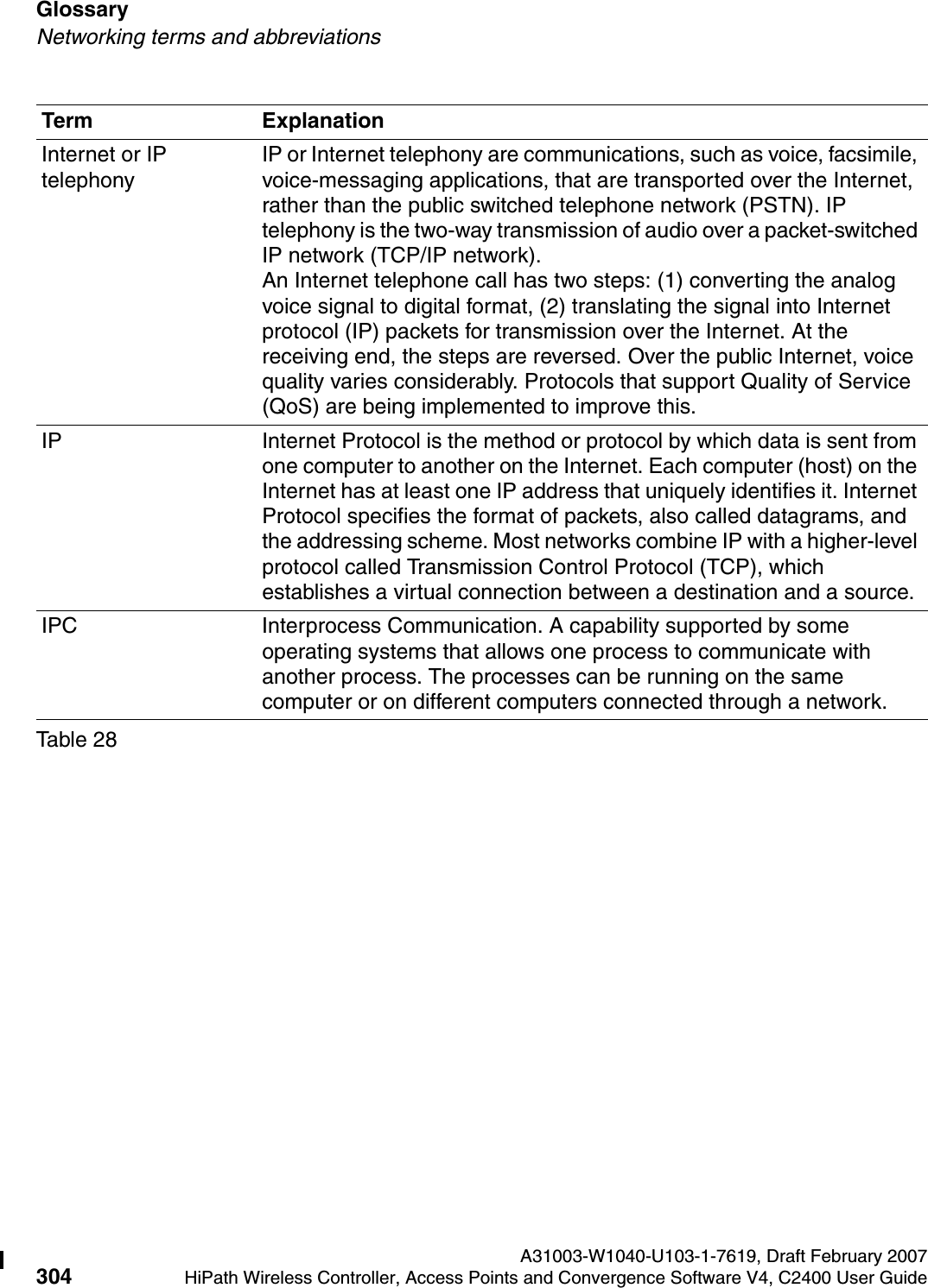
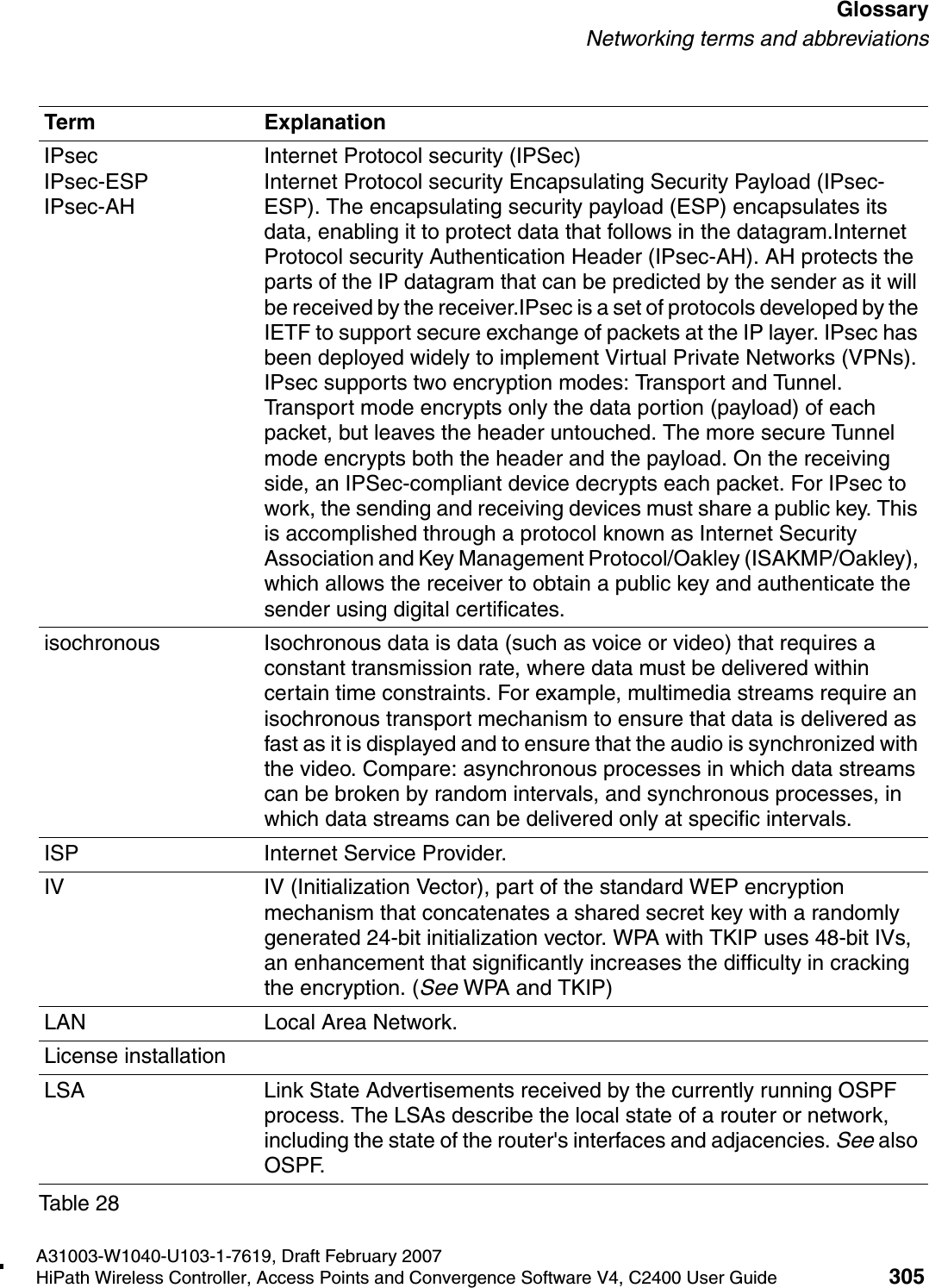
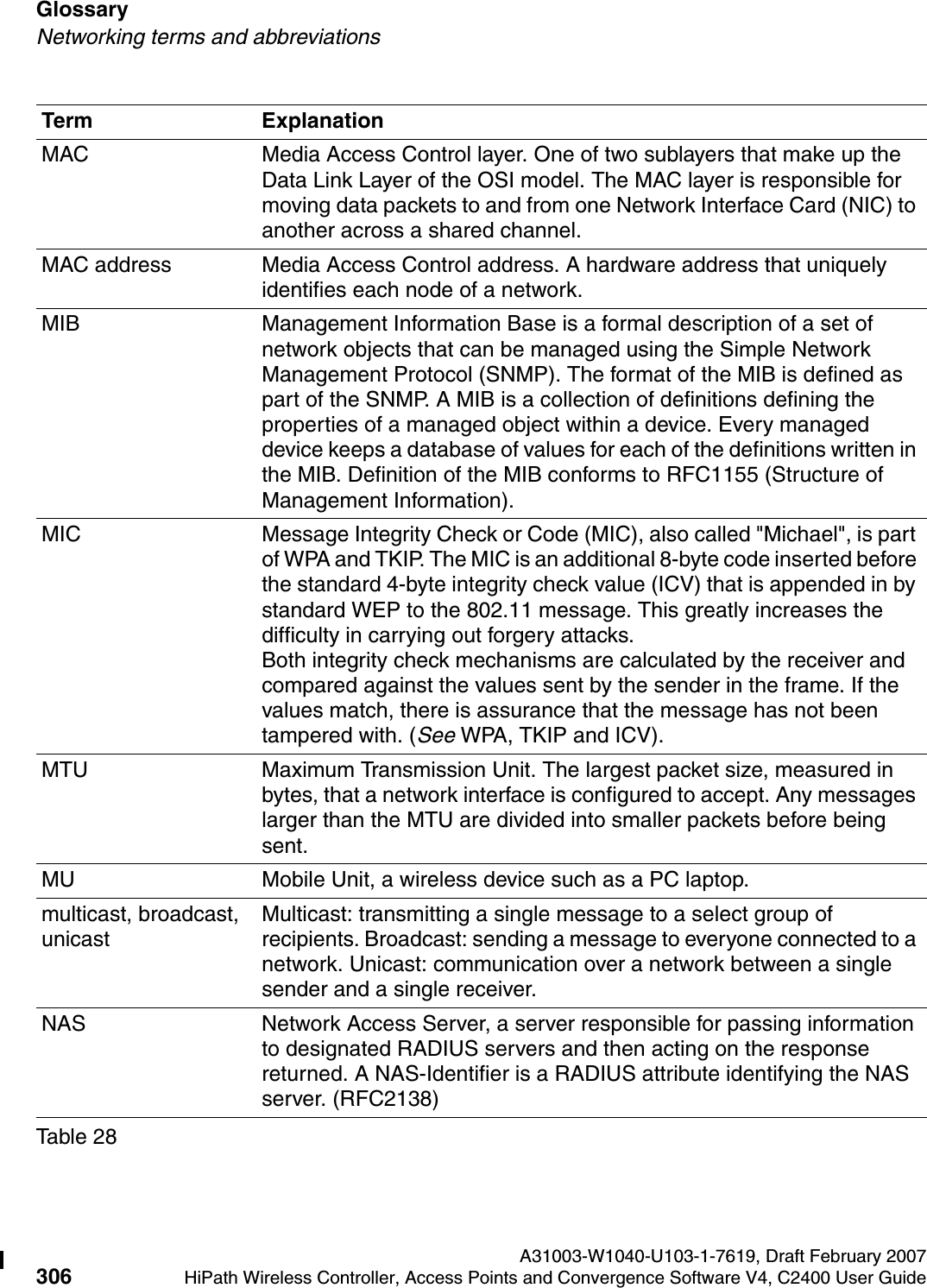
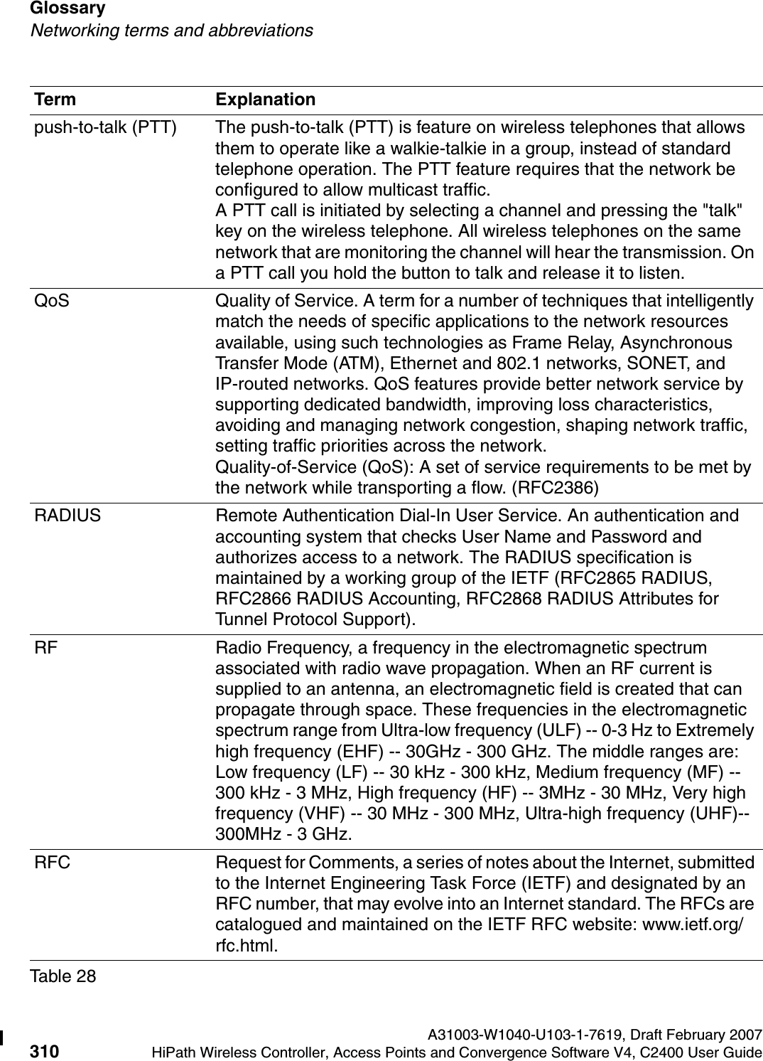
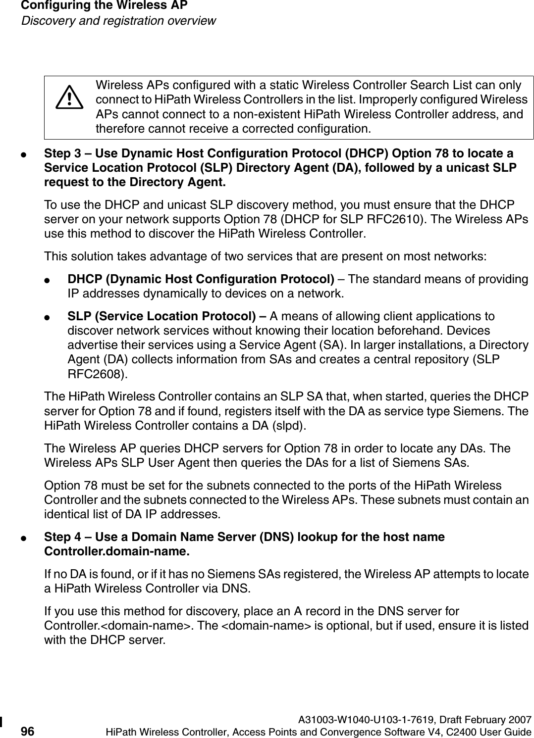
![Glossary A31003-W1040-U103-1-7619, Draft February 2007302 HiPath Wireless Controller, Access Points and Convergence Software V4, C2400 User Guide hwc_glossary.fmNetworking terms and abbreviationsFit, thin and fat APs A thin AP architecture uses two components: an access point that is essentially a stripped-down radio and a centralized management controller that handles the other WLAN system functions. Wired network switches are also required. A fit AP, a variation of the thin AP, handles the RF and encryption, while the central management controller, aware of the wireless users' identities and locations, handles secure roaming, quality of service, and user authentication. The central management controller also handles AP configuration and management. A fat (or thick) AP architecture concentrates all the WLAN intelligence in the access point. The AP handles the radio frequency (RF) communication, as well as authenticating users, encrypting communications, secure roaming, WLAN management, and in some cases, network routing. FQDN Fully Qualified Domain Name. A "friendly" designation of a computer, of the general form computer.[subnetwork.].organization.domain. The FQDN names must be translated into an IP address in order for the resource to be found on a network, usually performed by a Domain Name Server.FTM Forwarding Table ManagerFTP File Transfer ProtocolGateway In the wireless world, an access point with additional software capabilities such as providing NAT and DHCP. Gateways may also provide VPN support, roaming, firewalls, various levels of security, etc. Gigabit Ethernet The high data rate of the Ethernet standard, supporting data rates of 1 gigabit (1,000 megabits) per second.GUI Graphical User InterfaceHeartbeat message A heartbeat message is a UDP data packet used to monitor a data connection, polling to see if the connection is still alive.In general terms, a heartbeat is a signal emitted at regular intervals by software to demonstrate that it is still alive. In networking, a heartbeat is the signal emitted by a Level 2 Ethernet transceiver at the end of every packet to show that the collision-detection circuit is still connected.Term ExplanationTable 28](https://usermanual.wiki/Chantry-Networks/APXXX1.USERS-MANUAL-1/User-Guide-755957-Page-302.png)