Checkpoint Systems FX2012 Electronic Article Surveillance Detection System User Manual FX 2012 Installation Guide Part 1
Checkpoint Systems Inc Electronic Article Surveillance Detection System FX 2012 Installation Guide Part 1
Contents
- 1. FX 2012 Installation Guide Part 1
- 2. FX 2012 Installation Guide Part 2
- 3. FX 2012 Installation Guide Part 3
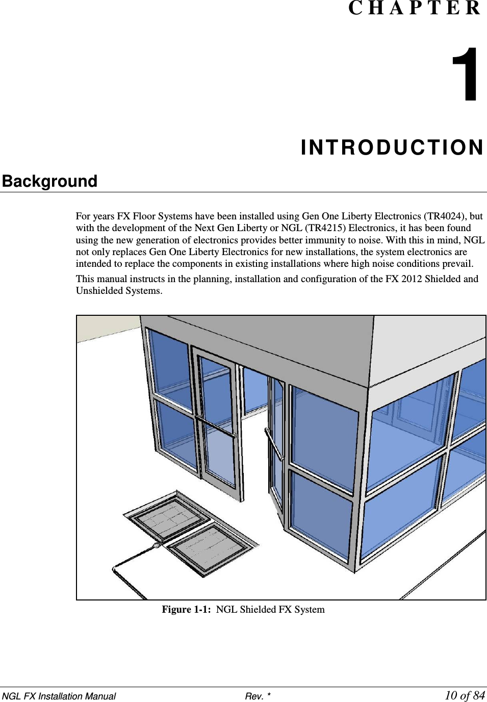
FX 2012 Installation Guide Part 1
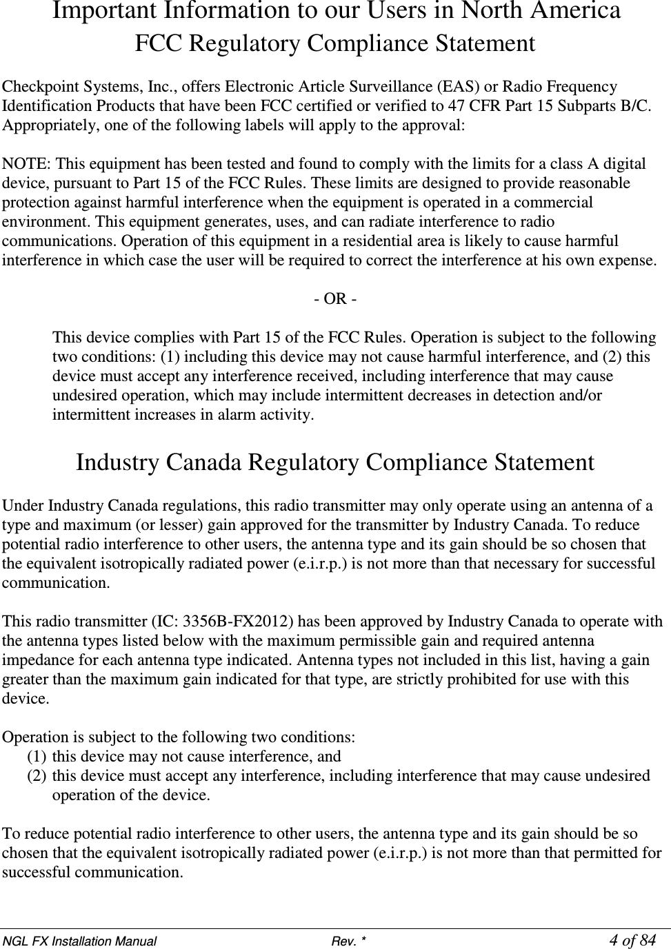
![NGL FX Installation Manual Rev. * 3 of 84 Statements • The device(s) may only be used for the intended purpose designed by for the manufacturer. • Unauthorized changes and the use of spare parts and additional devices which have not been sold or recommended by the manufacturer may cause fire, electric shocks or injuries. Such unauthorized measures shall exclude any liability by the manufacturer. • The liability-prescriptions of the manufacturer in the issue valid at the time of purchase are valid for the device. The manufacturer shall not be held legally responsible for inaccuracies, errors, or omissions in the manual or automatically set parameters for a device or for an incorrect application of a device. • Repairs may only be executed by the manufacturer. • Installation, operation, and maintenance procedures should only be carried out by qualified personnel. • Use of the device and its installation must be in accordance with national legal requirements and local electrical codes. • When working on devices the valid safety regulations must be observed. • Before touching the device, the power supply must always be interrupted. Make sure that the device is without voltage by measuring. The fading of an operation control (LED) is not an indicator for an interrupted power supply or the device being out of voltage! • The installer or licensed electrician must follow all NEC and local codes. • All wires routed in the floor per article 725 must be Class 2 and be UL Listed. UL Recognized AWM may be employed, provided it is enclosed in Conduit of ENT. • Inter-pedestal wiring should not be directly installed in wet concrete. Guide Conventions Document conventions are described below: • This is a Warning icon. When it appears, it indicates a potentially hazardous situation, which if not avoided, could result in death or serious injury. • Caution: This is a Caution icon. When it appears, it indicates a potentially hazardous situation which if not avoided, could result in property damage or malfunction of equipment. • Note: This is a Tip icon. When it appears, the corresponding text indicates a helpful note or tip when using the feature. For all measurements: • To meet both CE and FCC requirements, all measurements will be listed in the following format: Metric [Imperial], for example: 46cm [18in] or 0.9m [3ft]. • Where non-S.I. units are applicable, such as 6’ x 4’ or 3/16”, the format is Unit (metric). Where on-screen computer instructions are given: Button Name - This describes a button or an on-screen command or drop-down selection. For example, the <DONE> button is represented in this document as Done. Key Name - This describes a keystroke on a keyboard. For example, Ctrl represents the control key.](https://usermanual.wiki/Checkpoint-Systems/FX2012.FX-2012-Installation-Guide-Part-1/User-Guide-1801558-Page-3.png)
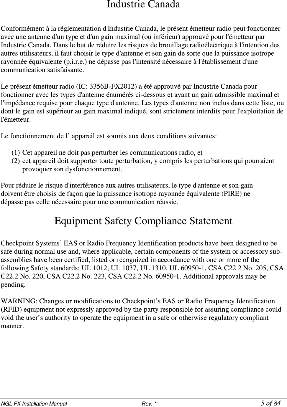


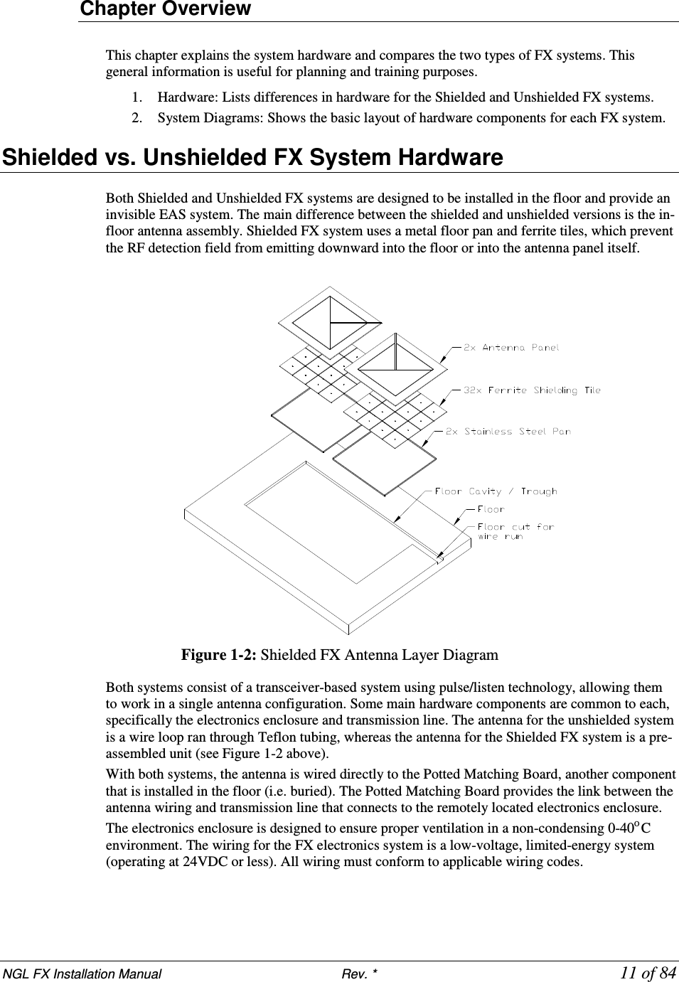
![NGL FX Installation Manual Rev. * 12 of 84 Shielded FX System Diagrams FX 2012 Shielded systems use antenna assemblies which are comprised of a Stainless Steel pan, ferrite shielding tiles, and PVC antenna panels. Figures 1.3 and 1.4 below show Shielded FX installations of varying width covering 1.8m and 2.7m door openings [6ft and 9ft, respectively]: Figure 1.3: Typical Shielded FX 1.8m [6ft] Installation Figure 1.4: Shielded FX 2.7m [9ft] Installation with Component Names](https://usermanual.wiki/Checkpoint-Systems/FX2012.FX-2012-Installation-Guide-Part-1/User-Guide-1801558-Page-12.png)
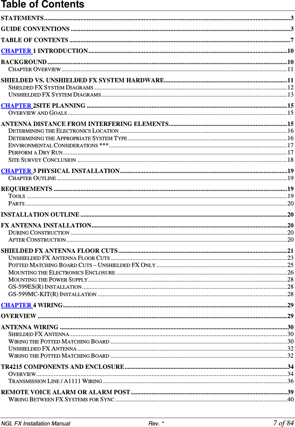
![NGL FX Installation Manual Rev. * 13 of 84 Unshielded FX System Diagrams Figures 1.5, 1.6, and 1.7 display views of an installation for both 1.2m [4ft] and 3.6m [12ft] door opening. Although not shown, a 1.8m [6ft] installation is also possible (see “Layouts”). Figure 1.5: Typical Unshielded FX 1.2m [4ft] Installation Figure 1.6: Typical Unshielded FX 3.6m [12ft] Installation](https://usermanual.wiki/Checkpoint-Systems/FX2012.FX-2012-Installation-Guide-Part-1/User-Guide-1801558-Page-13.png)
![NGL FX Installation Manual Rev. * 14 of 84 Coverage width spans from 0.91m [3ft] to 4.88m [16ft] for both Unshielded and Shielded FX systems. The 3.6m [12ft] door opening shown above is created by combining a 1.2m [4ft] and 2.4m [8ft] system together. Grouping multiple installation kits together is possible, but while wider openings can be covered, it requires approval from Checkpoint’s Product Management and confirmation of feasibility during the planning stage (refer to the “Site Survey”*** section below). Figure 1.7: Typical Unshielded FX 3.6m [12ft] Installation with Components Names](https://usermanual.wiki/Checkpoint-Systems/FX2012.FX-2012-Installation-Guide-Part-1/User-Guide-1801558-Page-14.png)
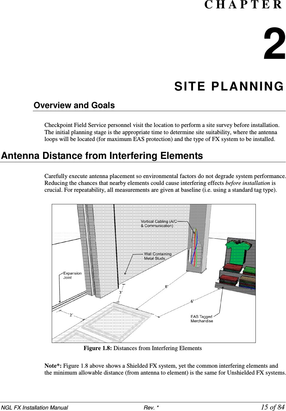
![NGL FX Installation Manual Rev. * 16 of 84 Common interfering elements and their minimum distances from an FX antenna are listed below: Expansion Joints: The minimum distance from an expansion joint is 0.6 m [2 ft]. Vertical Cabling: The minimum distance from vertical cabling is 2.4 m [8 ft]. Metal Wall Studs: The minimum distance from a metal wall stud is 0.9 m [3 ft]. Inward and Outward Swinging Doors (Metal): The minimum distance from a manual swinging metal door is 0.6 m [2 ft]. Note: The antenna must not be located below door when it is fully opened. Locate the FX system components beyond the door – with a minimum clearance gap of 0.3 m [12 in]. Sliding Doors (Metal): The minimum distance from a metal sliding door is 1.2 m [4 ft] Tagged Merchandise: The minimum distance from any tagged merchandise is 1.8 m [6 ft] Note*: For details about location of other systems, such as CP IX/D11 Deactivators, that may interfere with FX system operation, see appendix section X-Y***. Determining the Electronics Location FX antennas connect to the electronics enclosure, an integral device responsible for radio signal control and alarm detection. This enclosure and its power supply are mounted remotely, and environmental constraints must be taken into account. Determine an approximate location of the electronics enclosure during the Site Survey. Note*: The power supply can be mounted adjacent to the electronics enclosure, but this is not a requirement. Identify a location that is no further than 12.2m (40 linear-feet) or 15.2m (50 cable-feet) to allow for bends in the conduit run. The electronics enclosure is usually wall-mounted approximately 1.8m [6ft] above the floor to reduce RF-interaction between the electronics enclosure and any wiring in the ceiling or floor. Electronics mounted in the ceiling or rafters can potentially have a high RF-interaction with the surrounding environment, and therefore, may not perform optimally. Both the electronics enclosure and power supply are plenum-rated and can be installed above a drop ceiling or in HVAC areas. Determined whether or not this is necessary during the site survey, because the hood kit must be ordered separately. If the power supply is going to be located in the plenum, the Power Supply hood kit must be installed by a licensed electrician (CKP P/N 7367100) (GS-599MC-KIT(R). ***Note: Another option is to install the electronics enclosure in the plenum and locate the power supply outside the plenum (below the drop ceiling). During the following evaluation you can place the electronics enclosure and power supply on the floor, but strive to locate the electronics near their final locations (to avoid unintended noise later). Determining the Appropriate System Type It is the responsibility of Checkpoint Field Service Personnel (and/or Project Management) to identify environmental complications that would prevent any EAS system from being installed and operating properly. After arriving at the site, evaluate the surroundings for possible locations of in-ground antennas. Look for environmental factors that may affect the system, such as wiring, lighting, and floor construction. In particular, metal pan flooring (slab on metal deck) will effect RF detection; buildings with metal flooring are unlikely to be suitable for unshielded installations. The procedure known as a “dry run” helps you determine if the less-costly Unshielded FX system, which is more susceptible to noise, is the appropriate FX system type. Unshielded systems are installed in situations where coupling to metallic objects in the floor is not an issue.](https://usermanual.wiki/Checkpoint-Systems/FX2012.FX-2012-Installation-Guide-Part-1/User-Guide-1801558-Page-16.png)
![NGL FX Installation Manual Rev. * 17 of 84 ***FX Performance Environmental Considerations *** FX systems are not approved for operation in a wet environment, so this procedure is meant for dry installations only. The ideal location of the antenna(s) is where the water table does not interfere (i.e. water drains away from in-floor assembly and does not pool above). Note***: It is recommended that if the slab is on grade that the concrete be poured above a vapor barrier to prevent moisture from rising, thus keeping the slab dry. The store's architect will recommend the maximum permissible loading in the floor area where FX-Shielded antenna panels are installed. The architect must consider such factors as anticipated traffic over the floor and the material characteristics of the flooring (if covered above concrete). The weight of the floor should not rest on the antenna(s). The guidelines included in this guide assume installation into concrete (typical), but the antennas may be placed above concrete if finished flooring, such as hardwood, laminate, tile or stone, will conceal. With all installations, the concrete and other materials above the antenna(s) cannot be metallic. For example, wire mesh cannot be used for reinforcement above the concrete. Tile grout and the mortar used to fill the antenna trenches MUST BE non-metallic and non-magnetic grout. As for the electronics, typical indoor environmental considerations must be met: Operating temperature is 0°C to +40°C [32° to 104°F]. Permissible humidity range is 10 to 75%. The UV Exposure requirement is the electronics enclosure must be located where it is not exposed to direct sunlight. However, locating the enclosure where it will be exposed to sunlight through glass is acceptable. Perform a Dry Run A “dry-run” can determine where potential problems might occur. The following procedure simulates an FX antenna in place to ensure proper final configuration of the complete system: 1. Build the Floor Loop Jig. The device consists of a piece of cardboard that is 0.9m x 1.5m [3ft x 5ft]. a. Cut out a rectangular piece of cardboard measuring 0.9m x 1.5m [3ft x 5ft]. b. Cut at least 14m [13.33ft] of 18 AWG Stranded wire, then form a rectangular loop that measures 61cm x 112cm (24” x 44”). Approximately 0.3m [1ft] of excess wire on both sides of the loop remains \. c. Duct tape the loop to surface of the cardboard, centering it appropriately. d. Allow extra wire to extend from the jig in the middle of one of the 61cm [24in] ends of the rectangle or the corner. Twist together the two ends until it forms a braid. Do not create more than 2 turns per 2.5 cm [2 turns per in]. 2. Plug the loop terminals into X device. ***specifics to the connection or electronics contol settings? Then power on the system. Test possible in-floor locations… Content to work with*** Test by moving the Floor Loop Jig from opening to opening; shift from Side to side while monitoring noise, see Chapter 6: Tuning*** until a suitable location is found. Typical performance --- measurements , different detection heights…](https://usermanual.wiki/Checkpoint-Systems/FX2012.FX-2012-Installation-Guide-Part-1/User-Guide-1801558-Page-17.png)
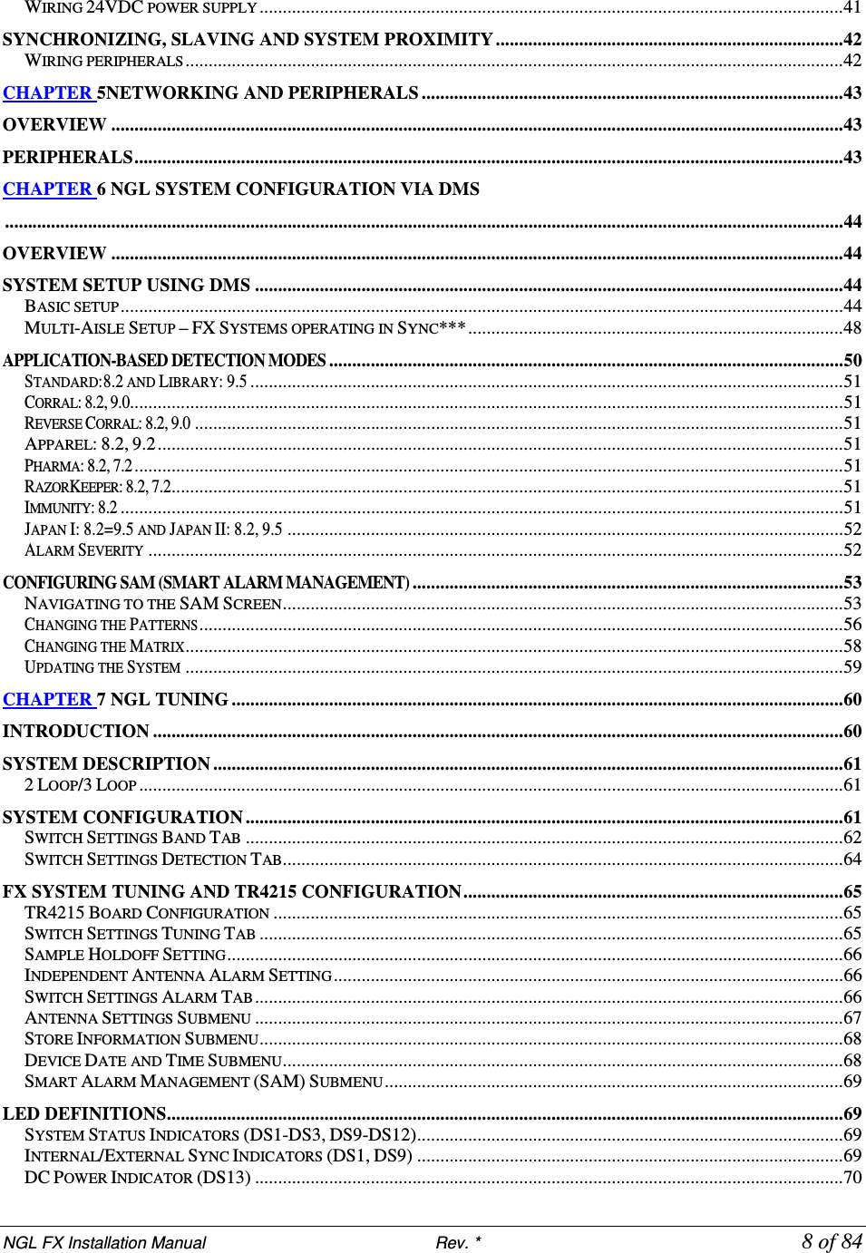
![NGL FX Installation Manual Rev. * 21 of 84 Shielded FX Antenna Floor Cuts Installing the FX antenna panels in an existing store requires a trough to be cut in the floor. If the site is under construction, it is easier to mold the system into the floor (explained above). These floor cut diagrams include the details on the size of the trough cuts required for each configuration. 101.6cm [40in]91cm[36in]FX Shielded Potted Matching Board (CKP P/N 7193007)FLOOR TROUGH –7.6 cm [3in] DeepTrough must be smooth and level Figure 5X***: FX Shielded w/Potted Matching Board for 0.9m [3ft] Opening Figure 6X***: FX Shielded w/Potted Matching Board for 1.8m [6’] Opening It is possible to create a wider system by combing either of the smaller two floor kits (Figures 3-1 and 3.2). For example, to cover a 2.7m [9’] mall opening, a 0.9m [3’] kit and a 1.8m [6’] kit would be ordered. Figure 3-3 (on the following page) shows the required floor cuts when a single antenna and double antenna are combined. Following that, two double antennas are installed side by side.](https://usermanual.wiki/Checkpoint-Systems/FX2012.FX-2012-Installation-Guide-Part-1/User-Guide-1801558-Page-21.png)
![NGL FX Installation Manual Rev. * 22 of 84 274cm [108in]FLOOR TROUGH –7.6 cm [3in] DeepTrough must be smooth and levelFX Shielded Potted Matching Board (CKP P/N 7193007)91cm[36in]91cm[36in]91cm[36in]91cm[36in] Figure 7X***: FX Shielded w/Potted Matching Board for 2.7m [9’] Opening Figure 8X***: FX Shielded w/Potted Matching Board for 3.7m [12’] Opening Figure 9: Shielded FX Matching Board Placement Note: The Potted Matching Board for the multi-panel FX system must be positioned between panels and not outside (a different placement compared to Unshielded systems).](https://usermanual.wiki/Checkpoint-Systems/FX2012.FX-2012-Installation-Guide-Part-1/User-Guide-1801558-Page-22.png)
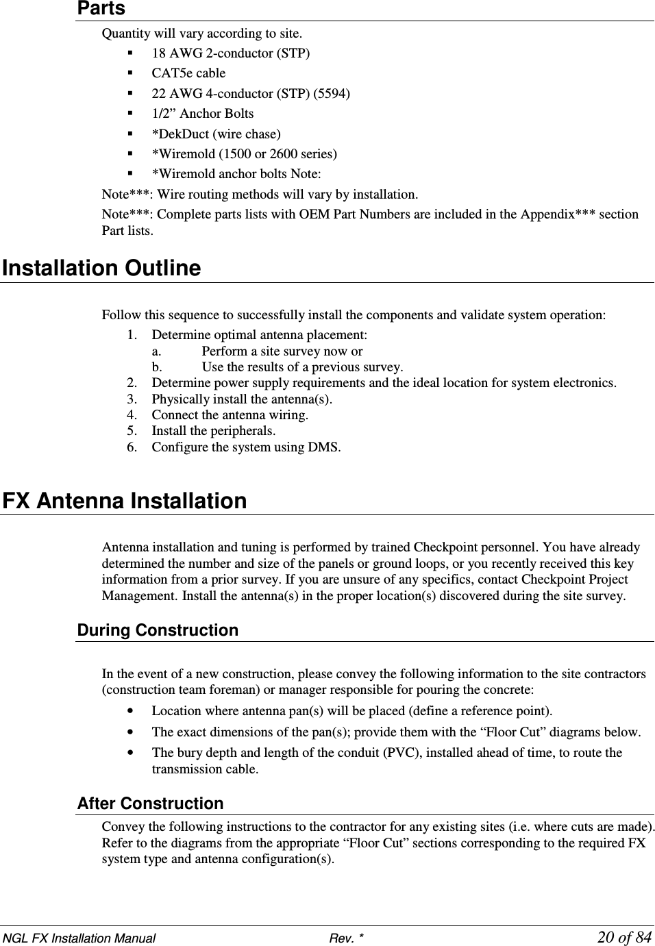
![NGL FX Installation Manual Rev. * 23 of 84 Unshielded FX Antenna Floor Cuts There are three (3) NGL Unshielded FX kits available: • Two Antenna • Single Antenna • Four Antenna Determine the version to be installed and then work with the contractor. Use the appropriate diagram to plan the floor cuts. Antenna floor cuts will measure approx. 5/16” wide and 3/4” deep (0.79cm and 1.9cm, respectively) for the Unshielded FX system. Note: The range for the antenna length dimension goes from 91.4cm [36in] minimum to 113.7cm [44in] maximum. Figure 23X***: Two-Antenna Installation Note: The floor trench specifications for two-antenna Unshielded FX systems are above. [36in] min 61cm ±1.9cm [24in ±0.75in] 113.7cm [44.75in] max 20.3cm [8in] Cavity cut into floor to house potted matching enclosure. Allow 15.2cm [6in] of space from cut edge to antenna loop. Refer to section X* below for cutout dimensions. 15.24m (50’) of 100 Ω direct burial rated transmission line to remote electronics. Wire should remain at least 0.6m [2ft] from the antenna wires. Install in conduit in new construction (pass along instructions). Location of Antenna Feedpoints Excess is 30.5cm ± 2.5 cm [12in ± 1in] long. Dress wires on top of each other in floor cut and seal ends of tubing with hot glue. Antenna wire, including feed point, is encapsulated in a single length of Teflon tubing. 91.4cm](https://usermanual.wiki/Checkpoint-Systems/FX2012.FX-2012-Installation-Guide-Part-1/User-Guide-1801558-Page-23.png)
![NGL FX Installation Manual Rev. * 24 of 84 Figure 24X***: Single-Antenna Installation Note: The floor trench specifications for a single-antenna Unshielded FX system are shown above. Note: Details on how the components are installed are written (on the specific parts) shown above. Please see notes on transmission line cable routing and conduit as note (complete instructions on wiring are found in “Wiring”). 20.3cm [8in] spacing to adjacent loop Figure 25X***: Four-Antenna Installation NOTE*: These kits can be combined to create larger systems. For example, to cover a 12 ft opening, a 4 ft kit and an 8 ft kit would be ordered. Antenna wire, including feed point, is encapsulated in a single length of Teflon tubing. 15.24m [50ft] of 100 Ω direct burial rated transmission line to remote electronics. Wire should remain at least 0.6m [2ft] from the antenna wires. Install in conduit in new construction (pass along instructions). Location of Antenna Feedpoint Excess is 30.5cm ± 2.5 cm [12in ± 1in] long. Dress wires on top of each other in floor cut and seal ends of tubing with hot glue.](https://usermanual.wiki/Checkpoint-Systems/FX2012.FX-2012-Installation-Guide-Part-1/User-Guide-1801558-Page-24.png)
![NGL FX Installation Manual Rev. * 25 of 84 Potted Matching Board Cuts – Unshielded FX Only The cavity for the potted matching PCB is to be placed 15.2cm [6in] from the antenna loops, centered between them. Plan the cuts for this cavity using the specifications below: Figure X***: Potted Matching Board Cavity](https://usermanual.wiki/Checkpoint-Systems/FX2012.FX-2012-Installation-Guide-Part-1/User-Guide-1801558-Page-25.png)
![NGL FX Installation Manual Rev. * 26 of 84 Figure X***27: Unshielded Floor Trench Specifications Mounting the Electronics Enclosure Instructions for locating the Electronics Enclosure are included below. It is important that the electronics enclosure be located no further than 12.2 linear-meters [40 linear-feet] from the antenna panels to allow for bends in the 15.2 cable meters [50 cable feet] run. The enclosure, which weighs 5.17kg [11.4lbs], has keyhole slots at its edges to facilitate mounting to the wall surface. The mounting hardware can support the weight of the unit. Do not mount the electronics enclosure beneath potential water sources (e.g. a sprinkler or pipe). The enclosure must have 2.5cm [1 in] clearance on all sides. It is suggested to locate the enclosure directly over (or nearest to) the conduit’s end wire as possible, ensuring the cable length is kept to a minimum. Limiting exposed cable prevents interference (but do not cut, see “Transmission Line,” and “Wrapped Cable” section). Use schedule 40 PVC conduit (contractor supplied) or wire run, such as Checkpoint approved Dek Duct, to route the cable. Installation procedures are listed for each type of material on which the enclosure can be installed: • Wood Surface, • Drywall, and • Concrete.](https://usermanual.wiki/Checkpoint-Systems/FX2012.FX-2012-Installation-Guide-Part-1/User-Guide-1801558-Page-26.png)
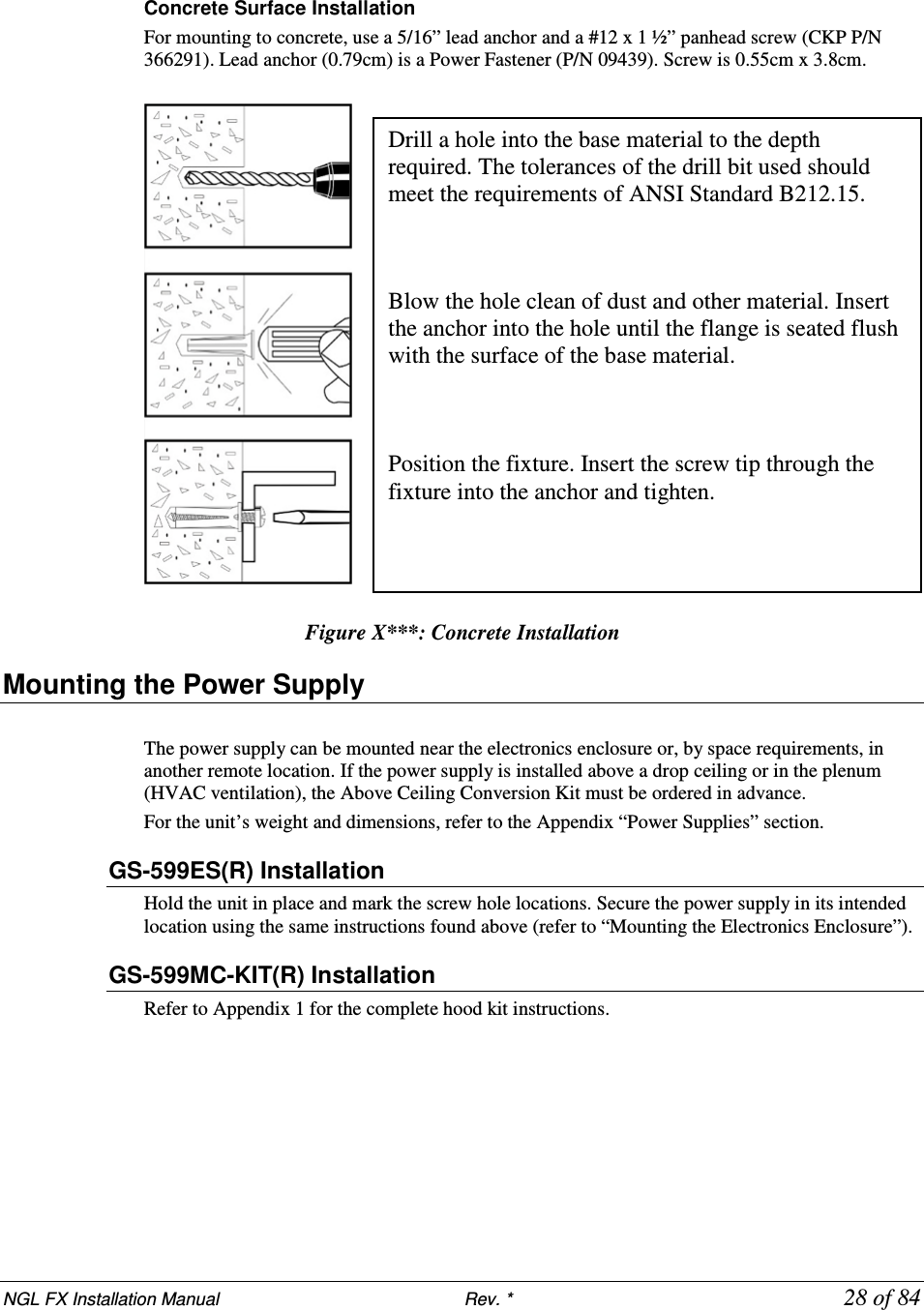
![NGL FX Installation Manual Rev. * 27 of 84 Wood Surface Installation For mounting to wood, use a #7 x ½” (0.38cm x 1.3cm) hex head screw (CKP P/N 7939172). Figure X***: Wood Surface Installation Drywall Surface Installation For mounting to drywall, use a #8 x 1” (0.42cm x 2.5cm) panhead screw (CKP P/N 7308823), which is a Power Fastener Zip-it (P/N 02348). Figure X***: Drywall Installation Using the proper diameter bit, drill a hole into the base material to a depth of at least 0.6cm [1/4”] deeper than the embedment required. Blow the hole clean of dust and other material. Select the installation tool and drive socket to be used. Insert the head of the screw into the hex head socket driver. Place the point of the screw through the fixture into the pre-dilled hole and drive the anchor in one steady continuous motion until it is fully seated at the proper embedment. Insert either # 2 or # 3 Phillips driver bit into the recess of the ZiP-It anchor head. Use a manual screwdriver or a low-rpm battery-powered electric screw gun. Push the ZiP-It anchor into the surface of the wallboard until the two cutting blades penetrate the surface. Using gentle forward pressure, rotate the ZiP-It until the collar sets flush to the surface of the wall. Put the fixture in place, insert screw and tighten until it feels secure. As the screw is threaded into the nylon versions, the point will expand resulting in increased load capacity in thicker wallboard. Note: When using an electric screw gun for application, set clutch and use slow speed (do not exceed approximately 300-400 RPM).](https://usermanual.wiki/Checkpoint-Systems/FX2012.FX-2012-Installation-Guide-Part-1/User-Guide-1801558-Page-27.png)
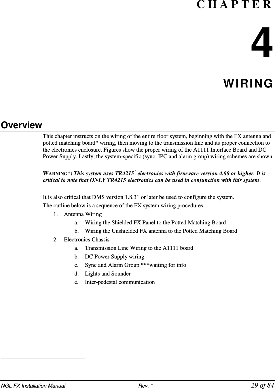
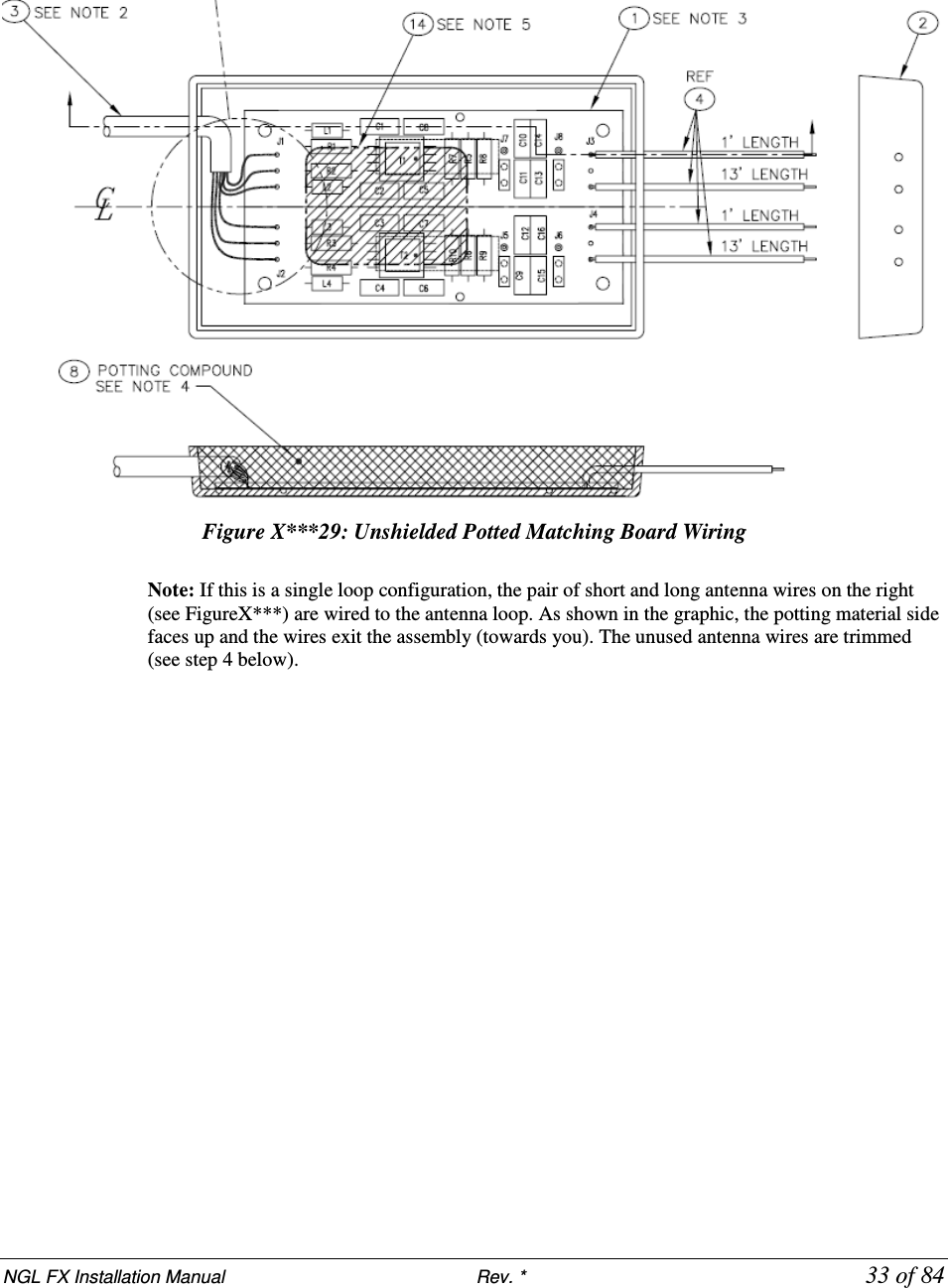
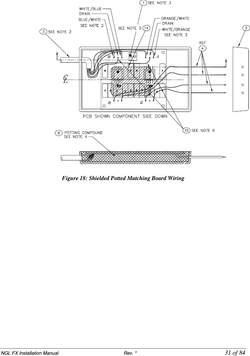
![NGL FX Installation Manual Rev. * 30 of 84 Antenna Wiring Recall the Potted Matching Board installation and wiring differs between Shielded and Unshielded FX systems. Instead of locating it in a separate cavity, the Shielded FX matching board is placed in the top center between the assemblies (or directly beside it, for a single loop). After successful hardware installation, the next step is wiring the antenna(s) to the matching board. Shielded FX Antenna Figure X below shows the proper wiring of the Shielded FX system. ***Graphic of Shielded system wired to PMB. Figure X***28: Shielded FX system Antenna Panel Note: If this is a single loop configuration, use the right pair of short and long antenna wires for the loop (right wires are with potting material facing up and wires exiting the potted matching assembly towards you). Trim the unused antenna wires at the potted matching board assembly. Wiring the Potted Matching Board Perform the following to wire the Potted Matching Board (CKP P/N 7193007) to the Shielded FX antenna system: 1. Connect the antenna wire to the 0.3m [1ft] wire adjacent to it (wire on the right side of the potted matching board with the potting side up) in the potted matching assembly using one of the provided wire nuts. 2. Strip the wire leads about 1.2cm (½”). Next, without pre-twisting the leads, align the wire conductors and then twist a wire nut onto each connector until hand tight. 3. Apply excess sealant in and around conductors. This forms a tight connection that will not fail once buried in the concrete. Refer to the “FX Antenna Floor Cuts” section for details on the placement of the potted matching board. The external and internal wiring before potting of the matching board (P/N 7193007) is displayed in Figure X***. Item 3 is the 15m [50ft] cable coming from the interface board. Item 4 displays the connections from J8 and J2 which are connected to the FX antenna. The fly wires from these ports are 0.3m [1ft] in length.](https://usermanual.wiki/Checkpoint-Systems/FX2012.FX-2012-Installation-Guide-Part-1/User-Guide-1801558-Page-30.png)
![NGL FX Installation Manual Rev. * 32 of 84 Unshielded FX Antenna The component list and wiring instructions for connecting the Unshielded FX system antenna loop to the potted matching board are below. Figure X***29 details the unshielded potted matching board’s electrical connections before potting is done. Figure X***: Potted Matching board and Unshielded FX Antenna Loop Components Wiring the Potted Matching Board Please note the placement of the potted matching board 15.24cm [6in] in front of the antenna instead of in between the antenna. The matching board for the Unshielded FX system has a different part number (CKP P/N 7113880), but has the same physical dimensions. 1. Determine the length of wire to be cut for antenna loop configuration(s). Cut long if unsure. 2. Insert the cross linked polyethylene-jacketed wire through the Teflon tubing. Allow the excess wire to stick out at either end of the tubing. 3. Starting about 3.8cm [1.5in] from the potted matching assembly, place the tubing in the cut trough. 4. Install the wire in the trench, feeding it around until the loop is complete. The antenna feed point will be 30.5cm +/- 2.5cm [12in +/- 1in] when trimmed. No extra wire is allowed because it may affect tuning. Note*: The Teflon tubing should be one continuous piece beginning at the assembly, through the cut for the pigtail, through the antenna loop cut, and back through the pigtail cut. One tube is positioned above the other at the pigtail location. Note*: Keep exposed wire (not in Teflon tubing) to a minimum leaving just enough to allow the wire nuts to be installed. The exposed wire should measure approximately 3.81 cm [1.5in]. 5. Next, seal the ends of the Teflon tubing completely with hot glue to prevent the infiltration of concrete or moisture.](https://usermanual.wiki/Checkpoint-Systems/FX2012.FX-2012-Installation-Guide-Part-1/User-Guide-1801558-Page-32.png)