Checkpoint Systems FX2012 Electronic Article Surveillance Detection System User Manual FX 2012 Installation Guide Part 3
Checkpoint Systems Inc Electronic Article Surveillance Detection System FX 2012 Installation Guide Part 3
Contents
- 1. FX 2012 Installation Guide Part 1
- 2. FX 2012 Installation Guide Part 2
- 3. FX 2012 Installation Guide Part 3
FX 2012 Installation Guide Part 3
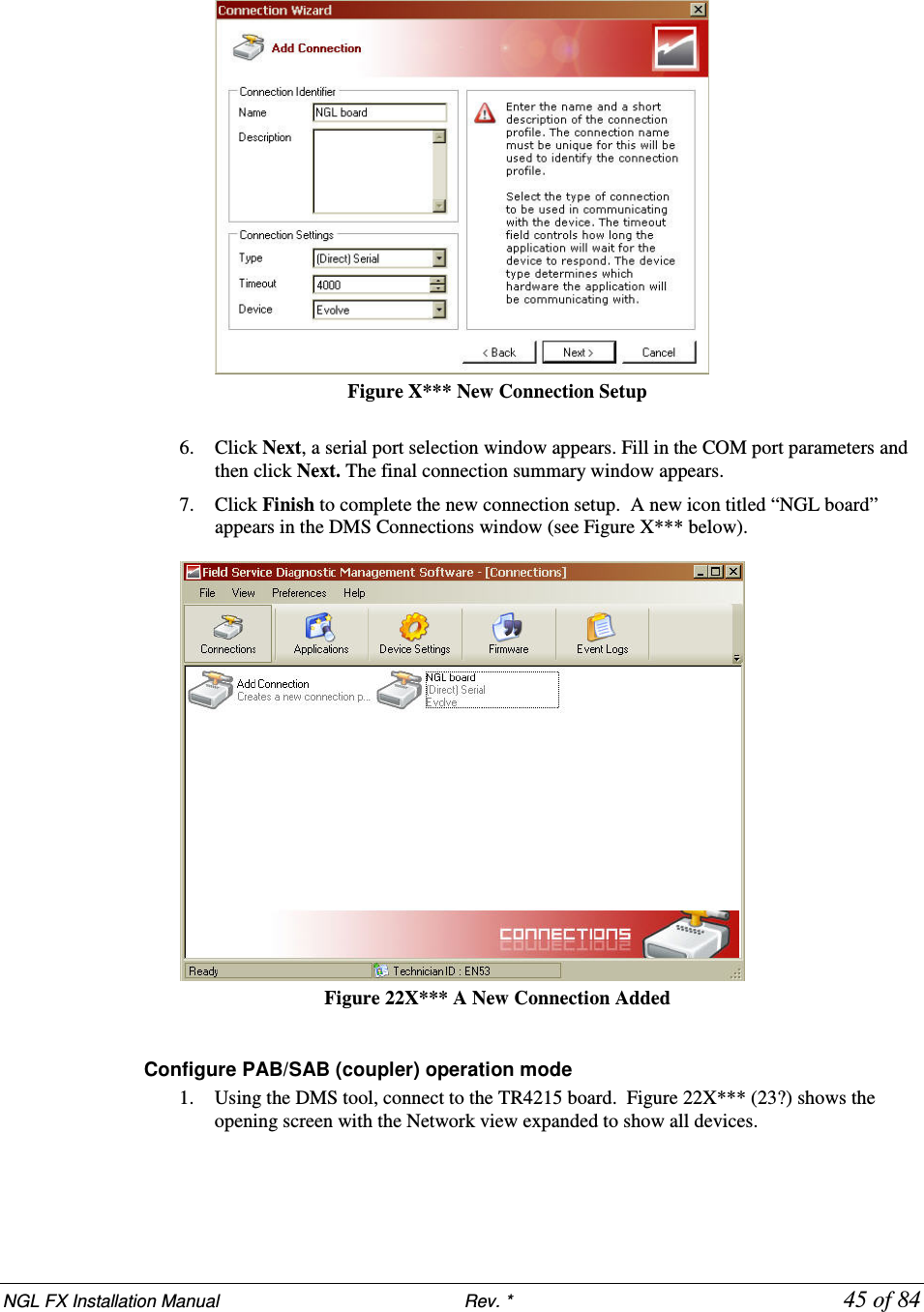
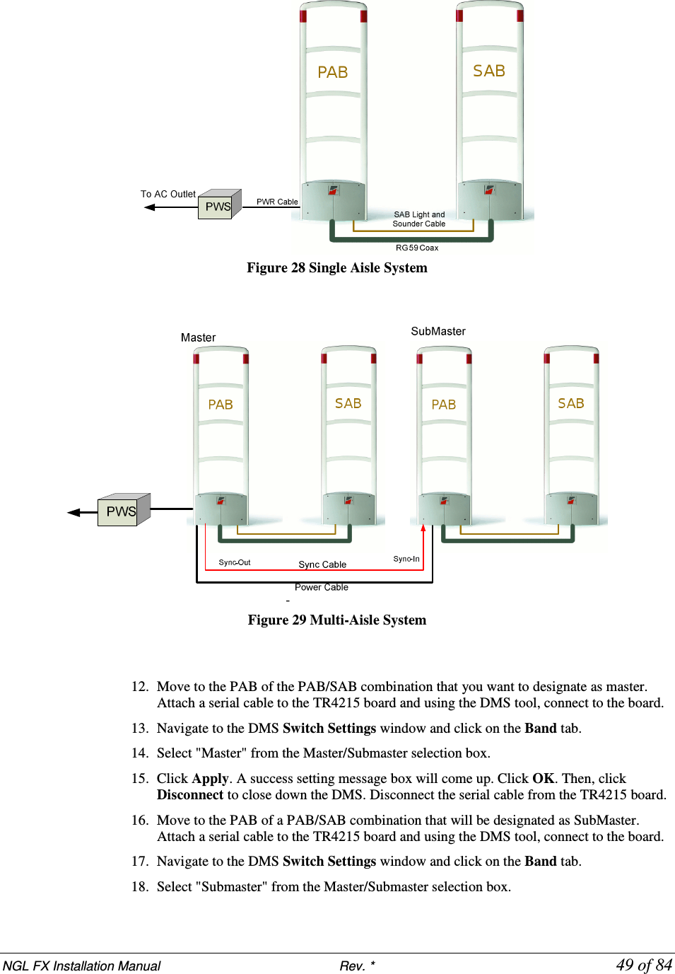
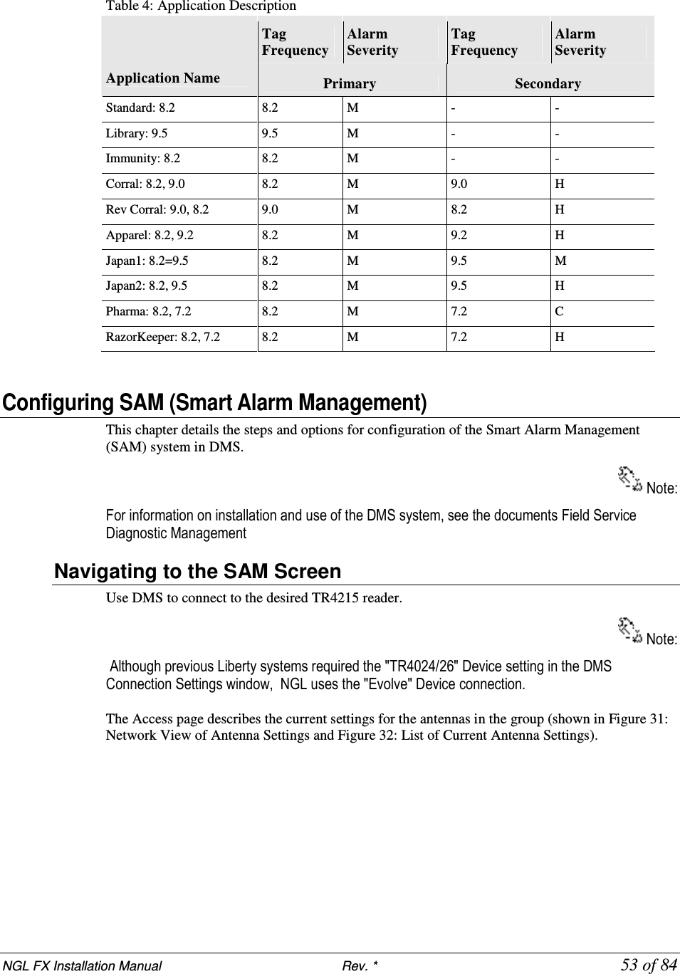
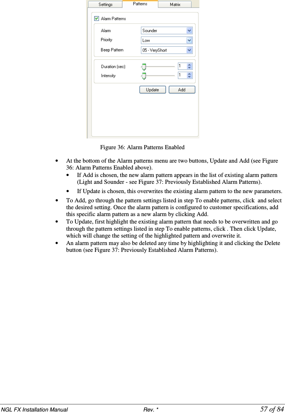
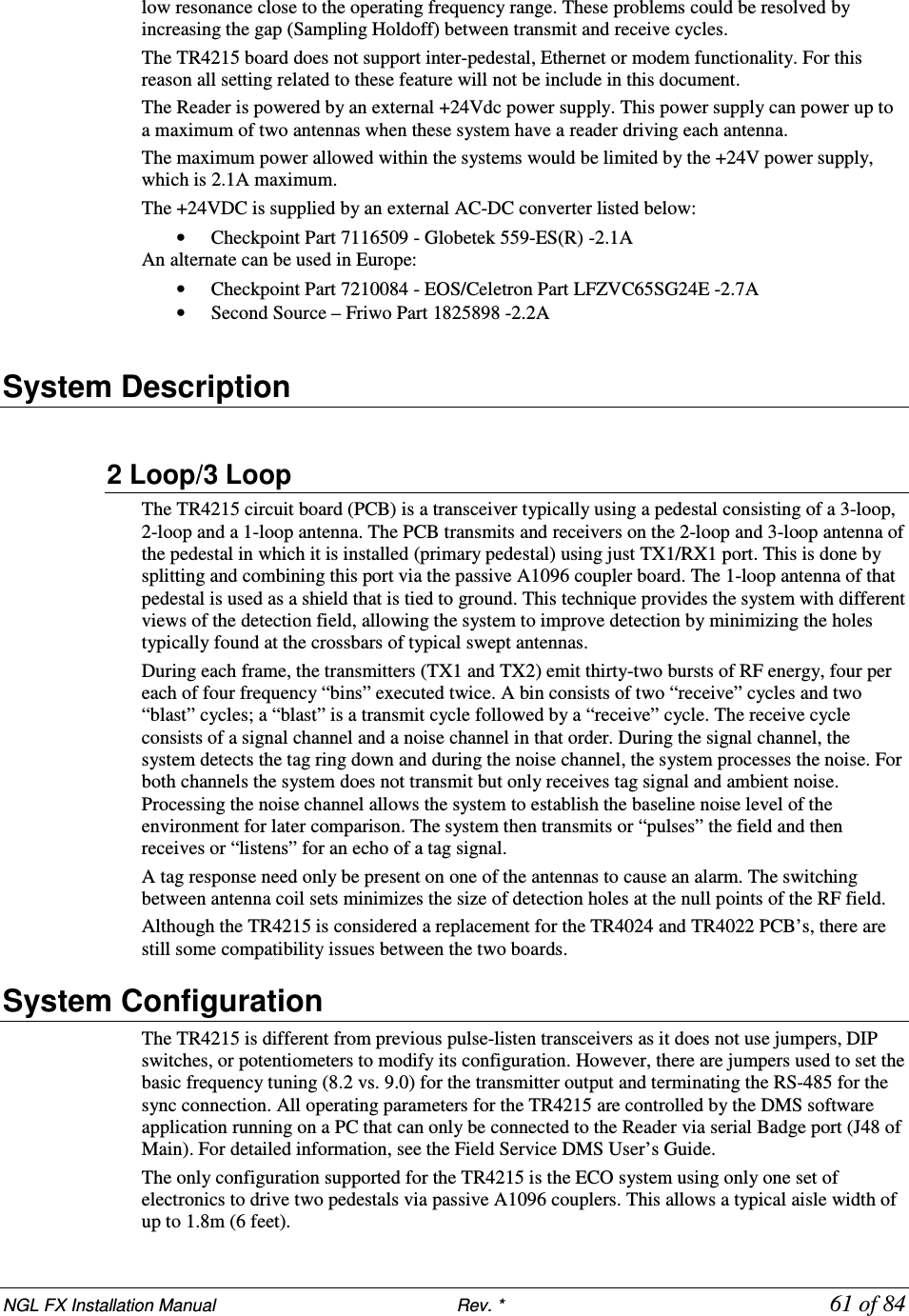
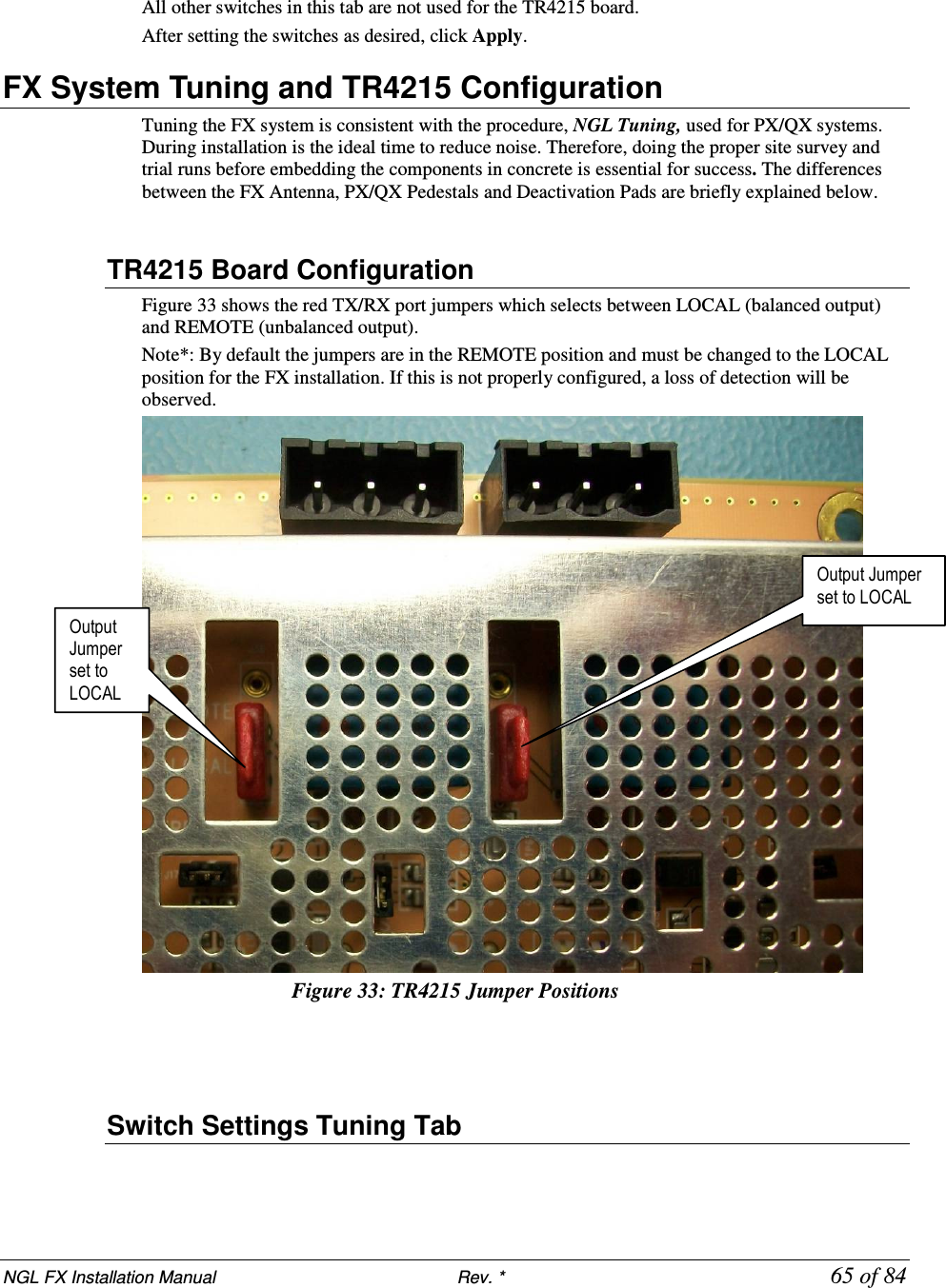
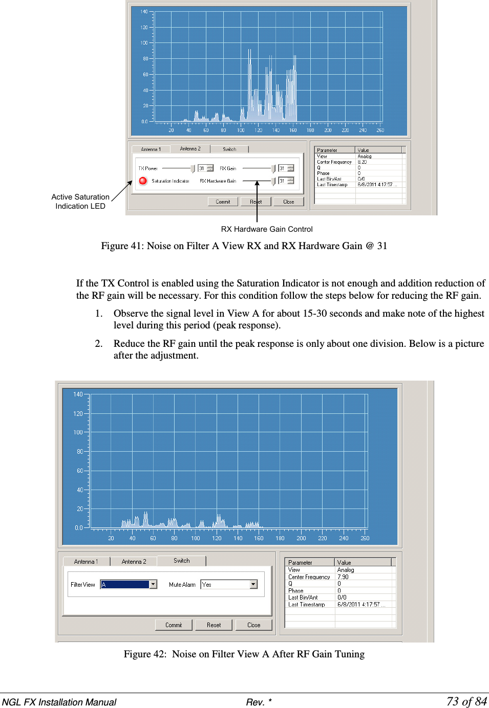
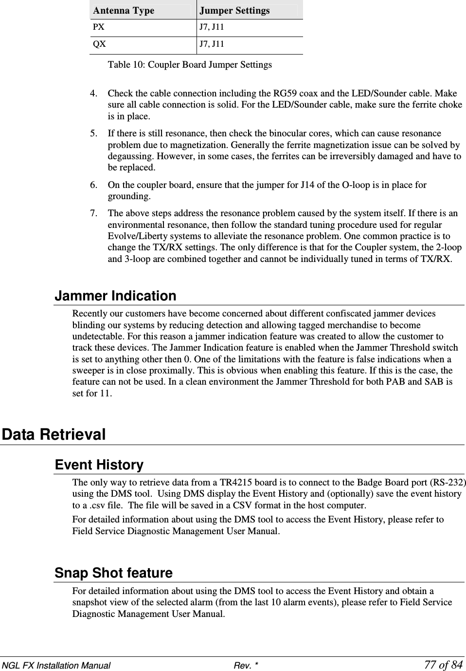
![NGL FX Installation Manual Rev. * 81 of 84 Dimensions Width: 10.50cm [4.13in] Length: 15.24cm [6.00in] Height: 8.64cm [3.40in] Power Supply Used in Australia Model The power supply used in Australia is the ETE 2.5A model, shown below. Specifications This unit operates at 240V 50Hz .38A; the output voltage remains 24VDC. Dimensions: Width:10.5cm Length 15.7cm Height: 7.0cm](https://usermanual.wiki/Checkpoint-Systems/FX2012.FX-2012-Installation-Guide-Part-3/User-Guide-1801560-Page-37.png)
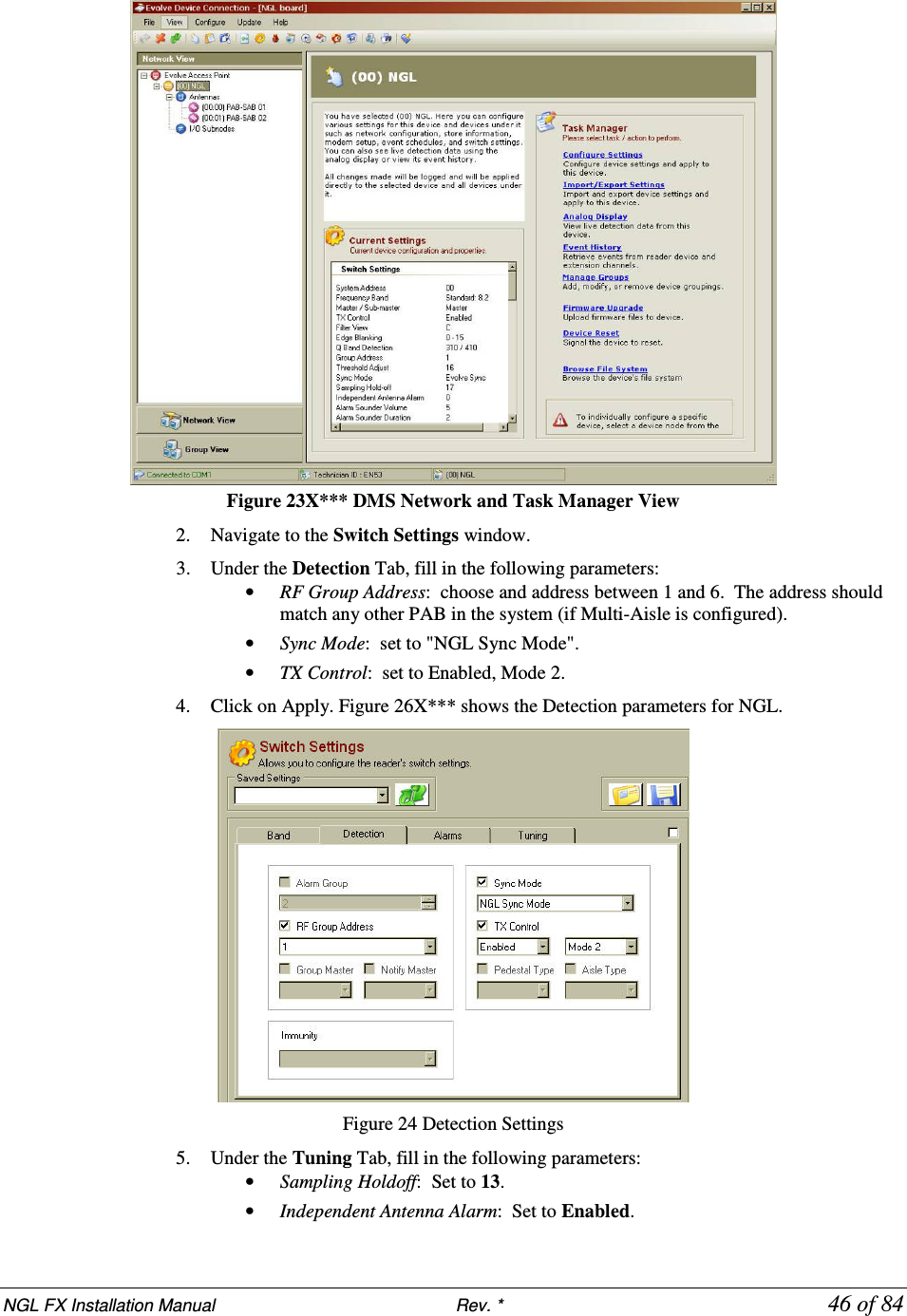
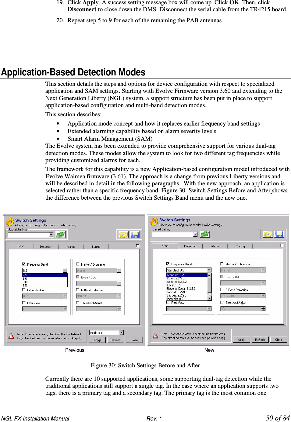
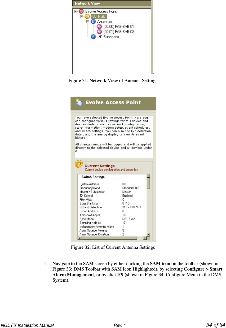
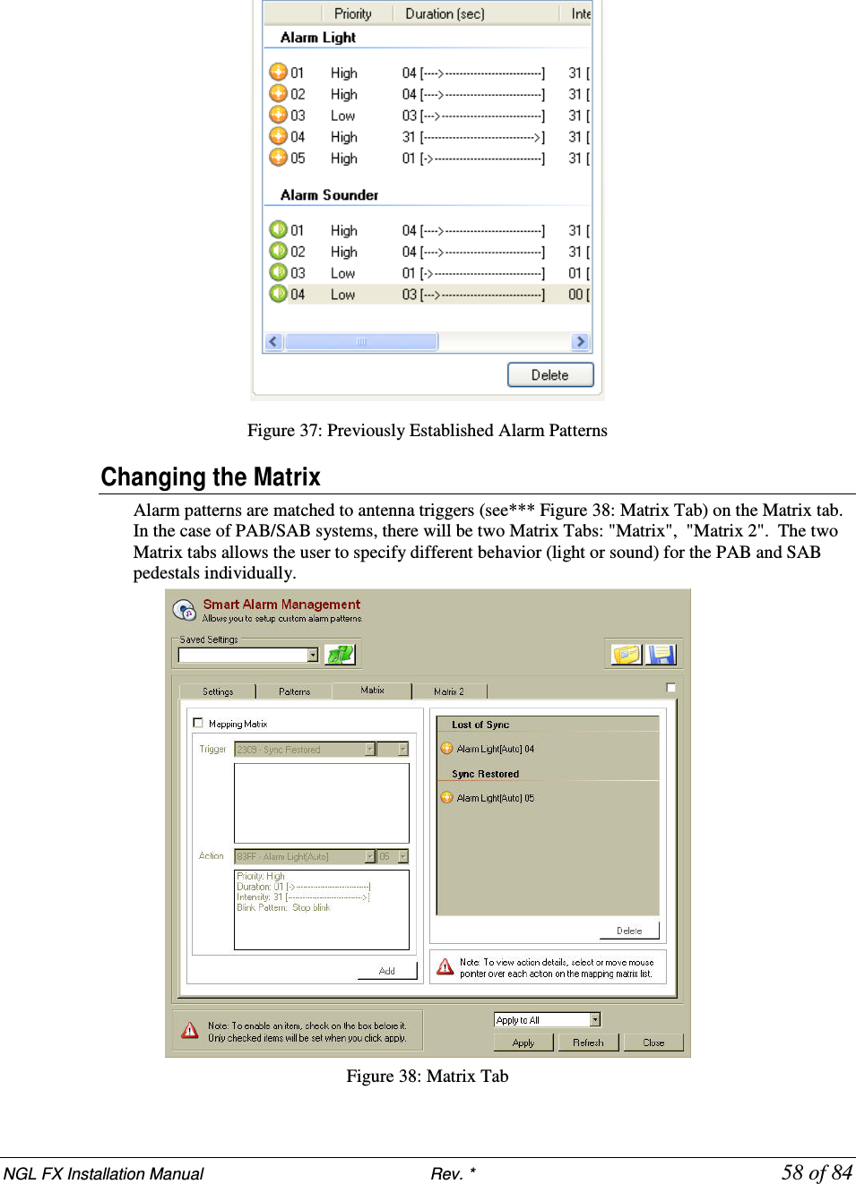
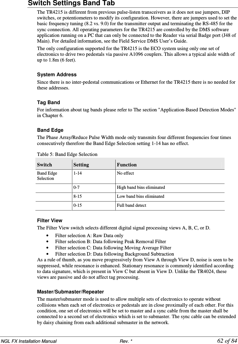
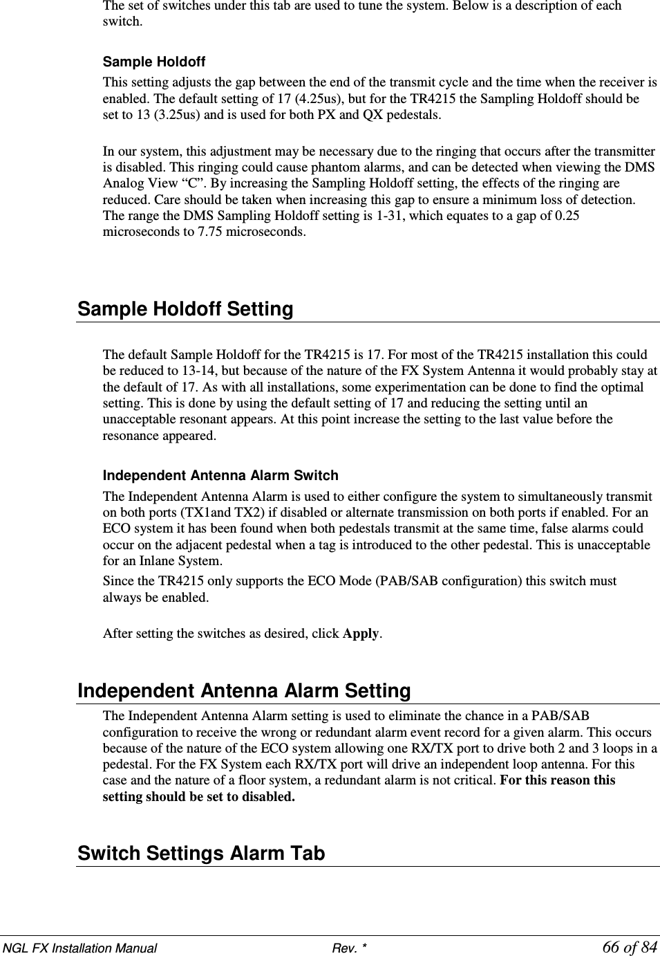
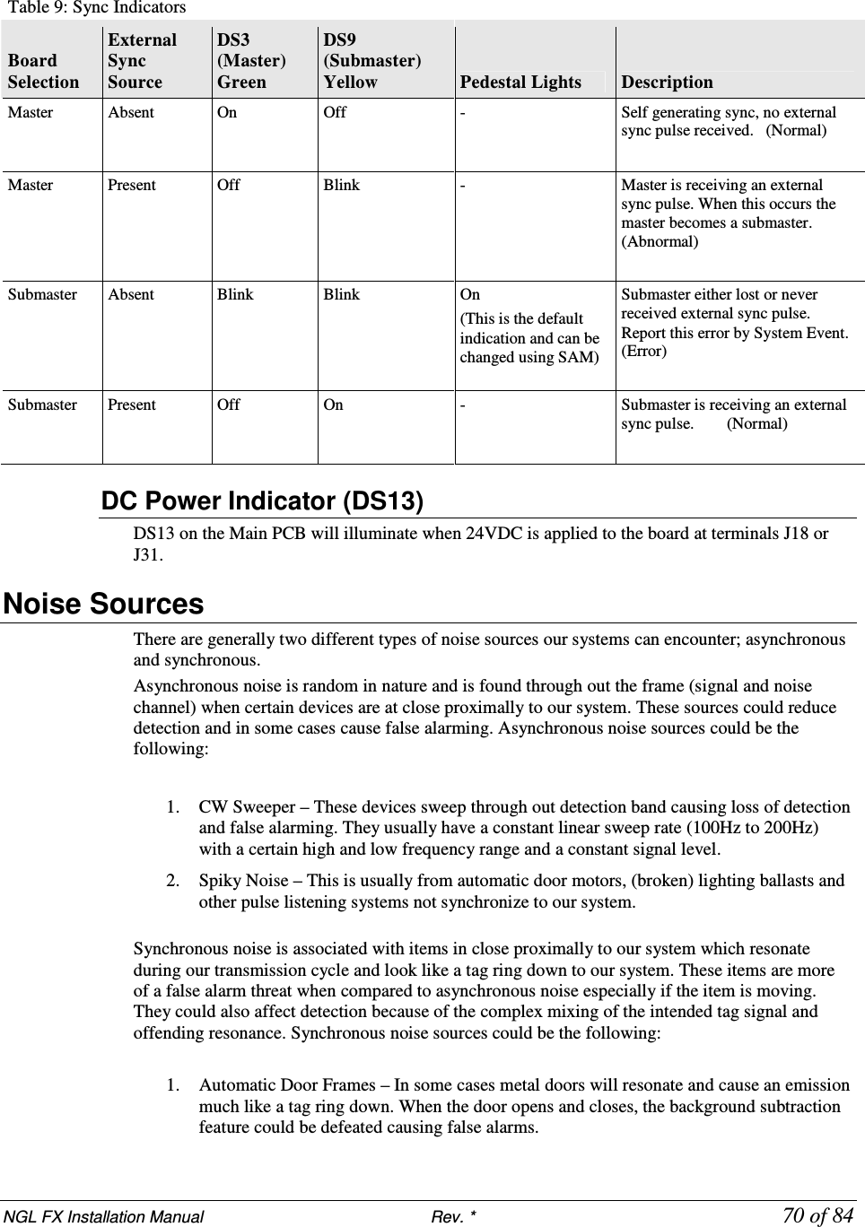
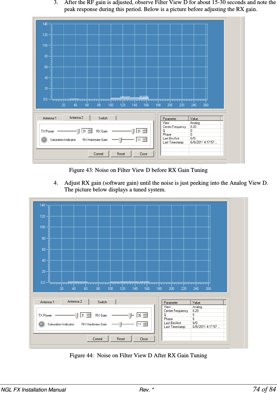
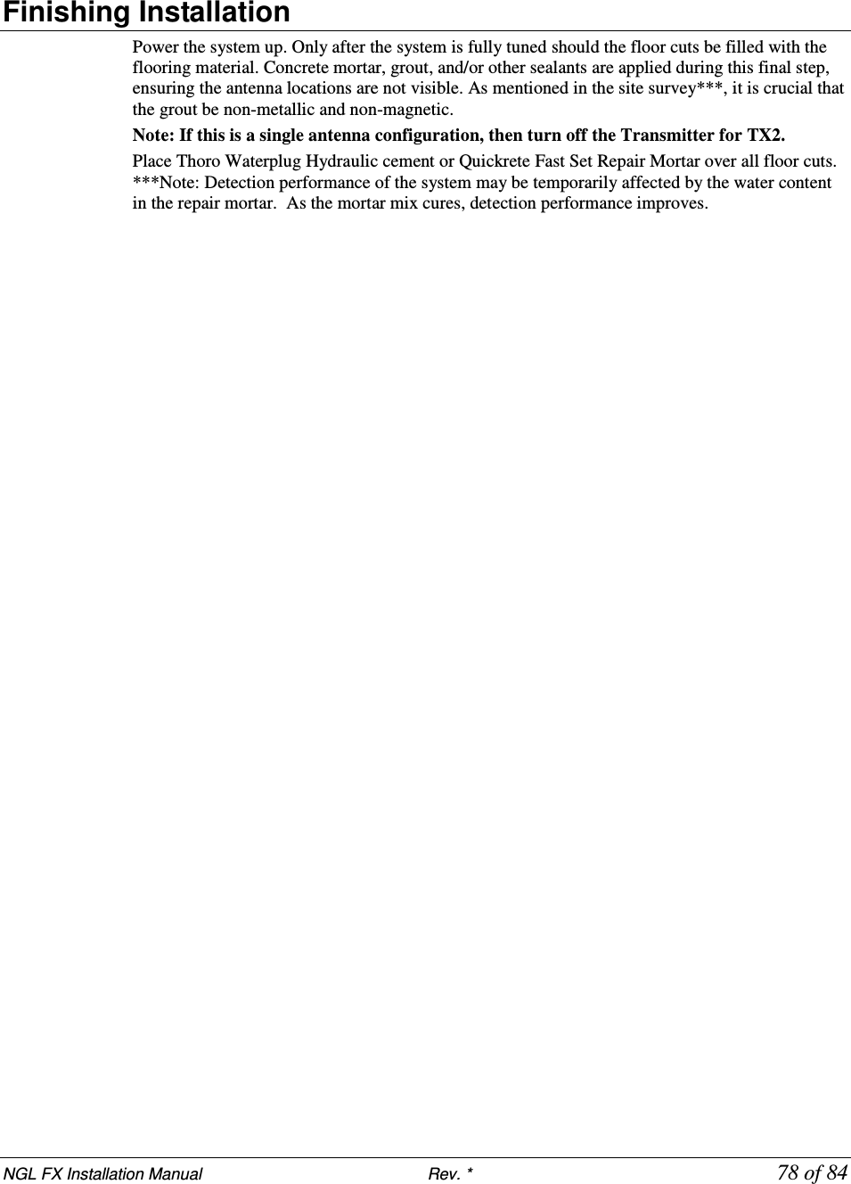
![NGL FX Installation Manual Rev. * 82 of 84 A P P E N D I X 3 PARTS LIS TS Shielded FX Parts List CKP Part # OEM Part # Description 7939172 n/a .38cm x 1.3cm (#7 x ½”) hex head screw 7308823 2348 Power Fastener Zip-it with .42cm x 2.5cm (#8 x 1”) panhead screw 7366291 9439 Power Fastener .79cm (5/16”) lead anchor 7917157 n/a 5.484 mm x 38.1 mm (#12 x 1 ½”) panhead screw 7257241 Belden 8723 Consolidated 5594 Approved Sync Cable 7327686 Dryconn 62110 or 62125 Waterproof wire nut Contractor Supplied T5002/1241 Thoro Waterplug Hydraulic Cement T5002, 10 lb can / Quickrete Fast Set Repair Mortar 1241 Contractor Supplied n/a Sand used to level bottom of trough under panels Contractor Supplied n/a 1.9cm (¾”) PVC conduit, contractor supplied. Used to house 15.1m [50ft] transmission line in new installations before slab is poured. Unshielded FX Parts List CKP Part # OEM Part # Description 7939172 n/a 0.38cm x 1.3cm (#7 x ½”) hex head screw 7308823 2348 Power Fastener Zip-it with 0.42cm x 2.5cm (#8 x 1”) panhead screw 7366291 9439 Power Fastener .79cm (5/16”) lead anchor 7917157 n/a 5.484 mm x 38.1 mm (#12 x 1 ½”) panhead screw 7257241 n/a Approved Sync Cable: Belden # 8723 & Consolidated # 5594 *** n/a 1.9cm (¾ inch) PVC conduit, contractor supplied 7327686 Dryconn 62110 Waterproof wire nut](https://usermanual.wiki/Checkpoint-Systems/FX2012.FX-2012-Installation-Guide-Part-3/User-Guide-1801560-Page-38.png)
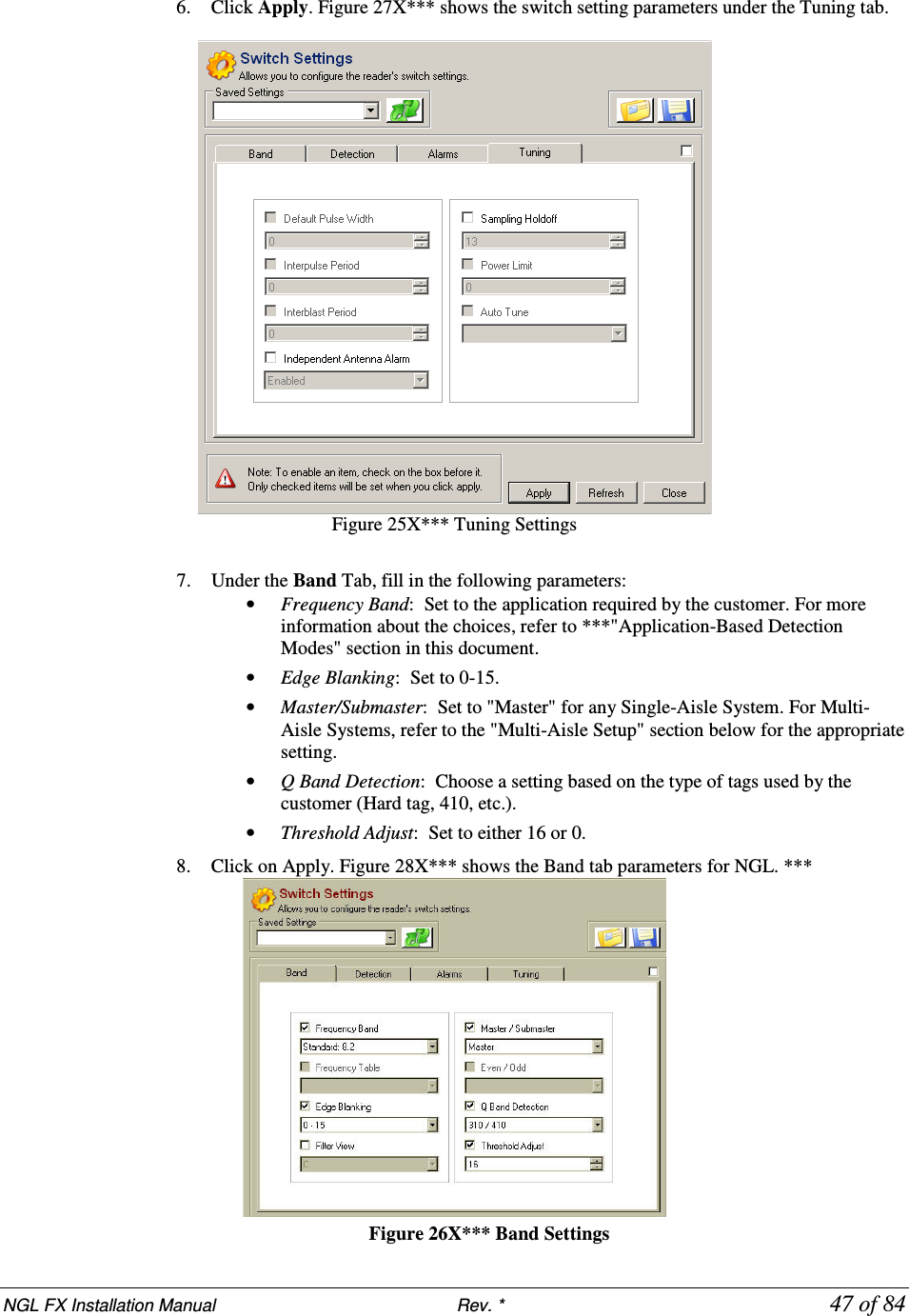
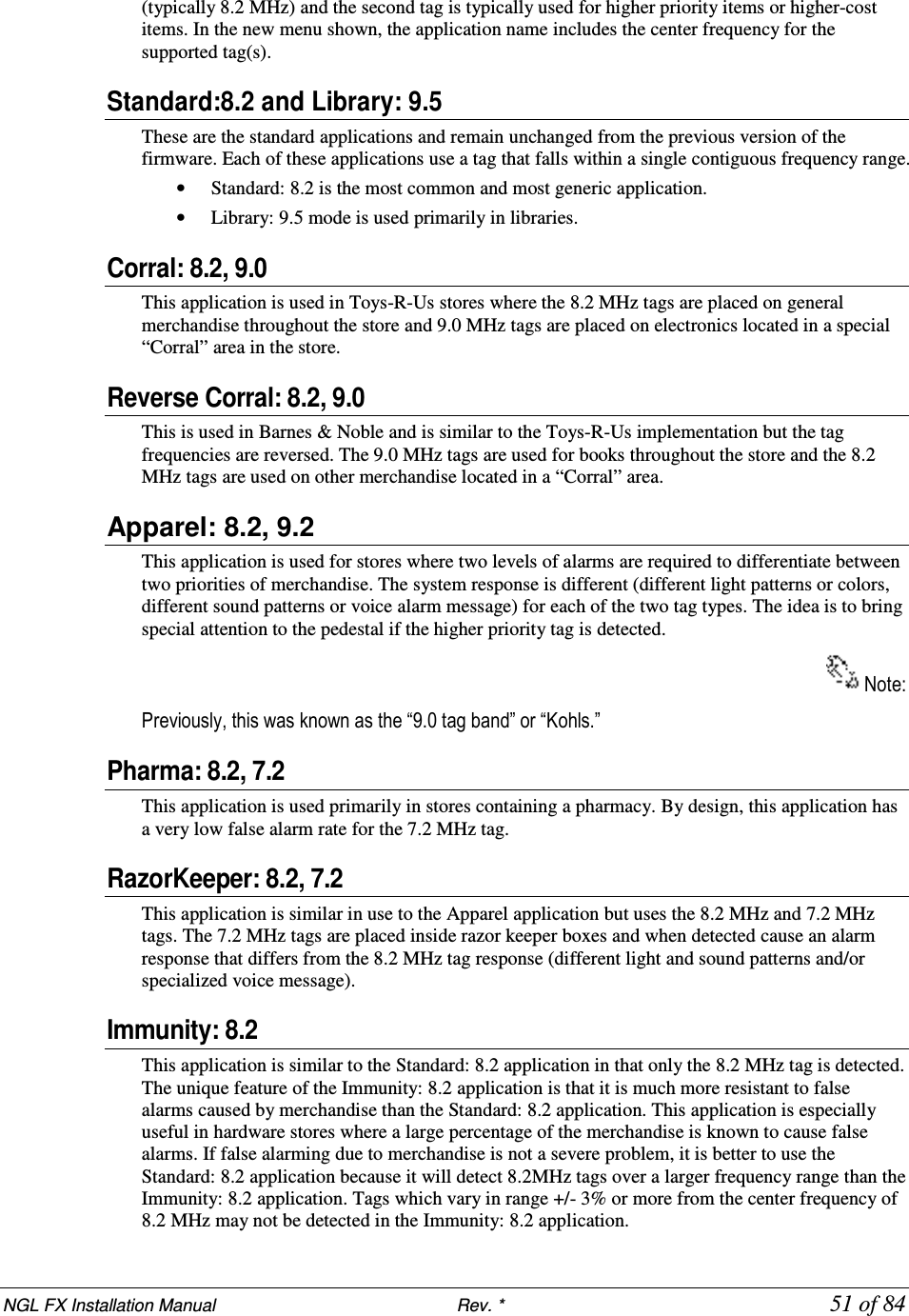
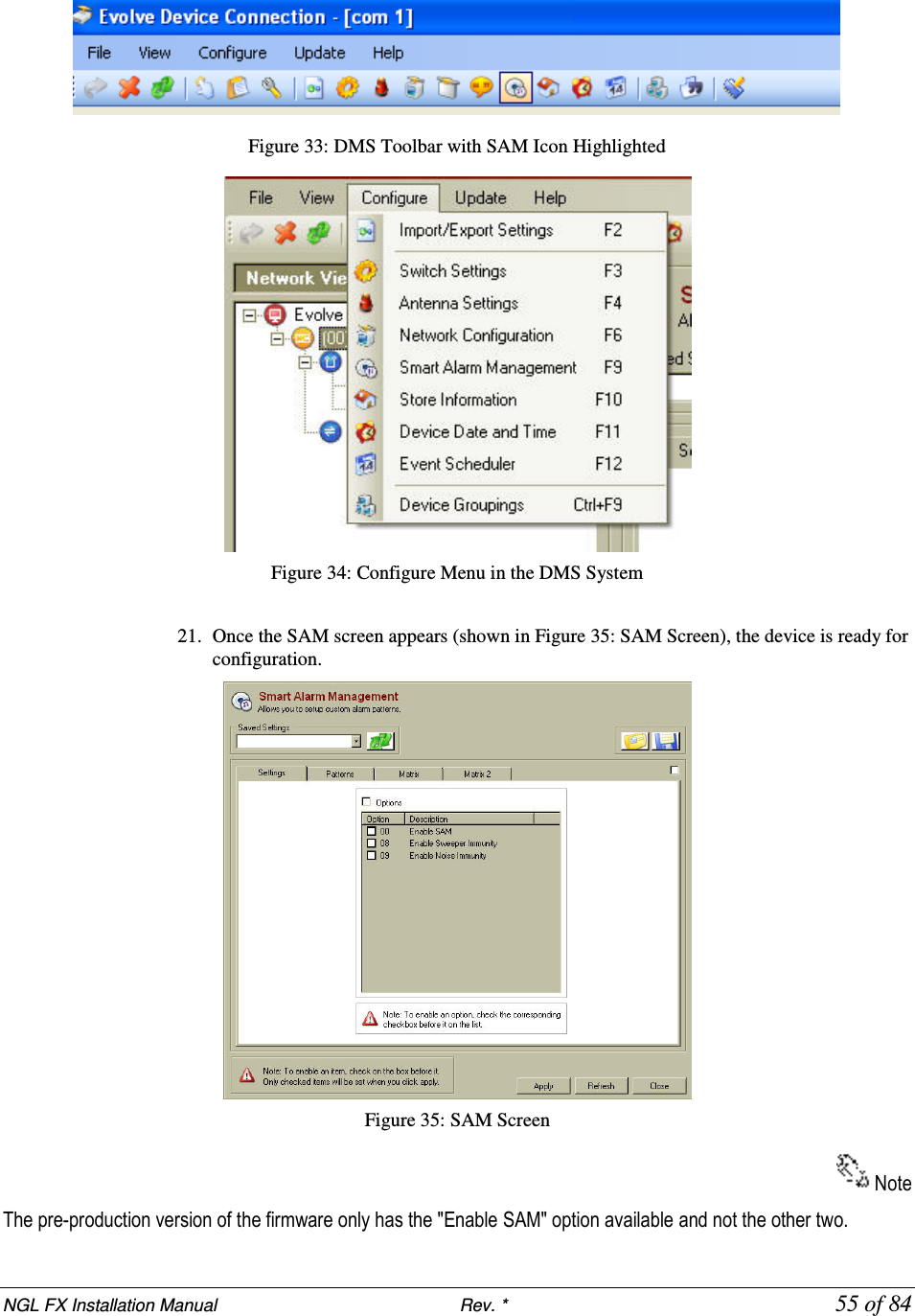
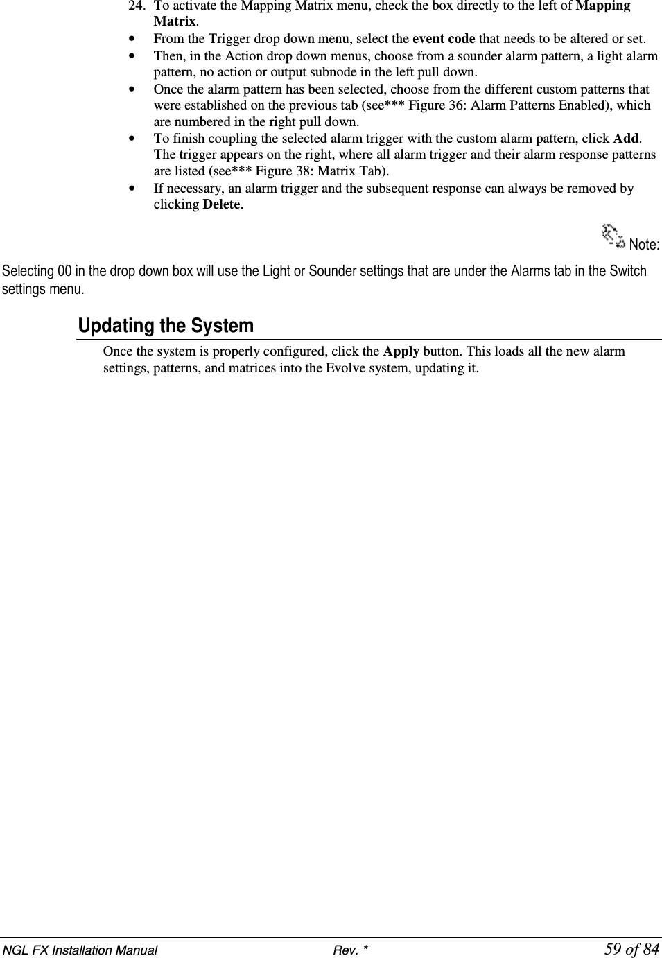
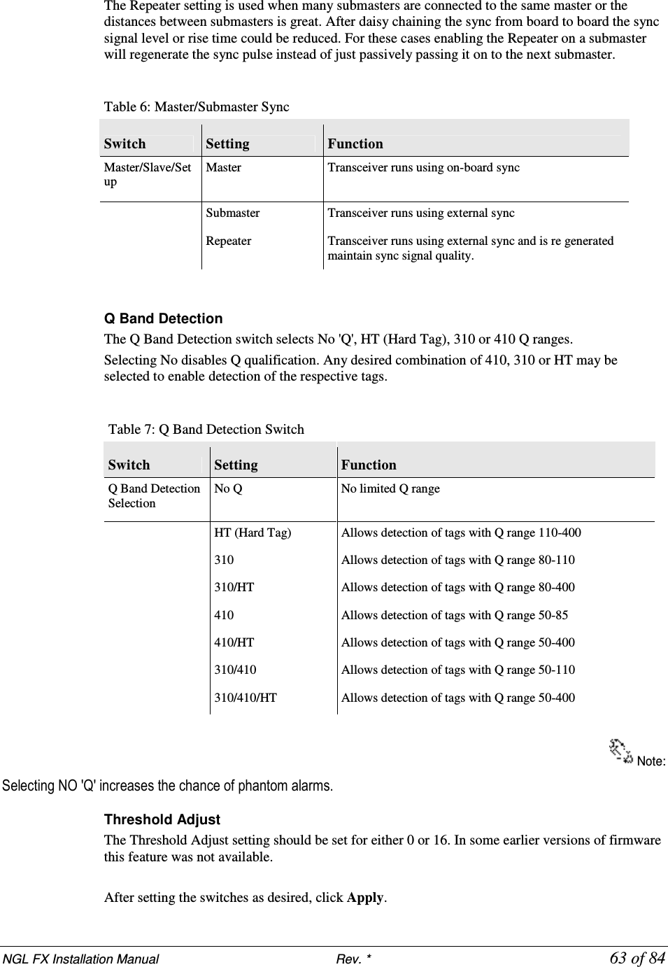
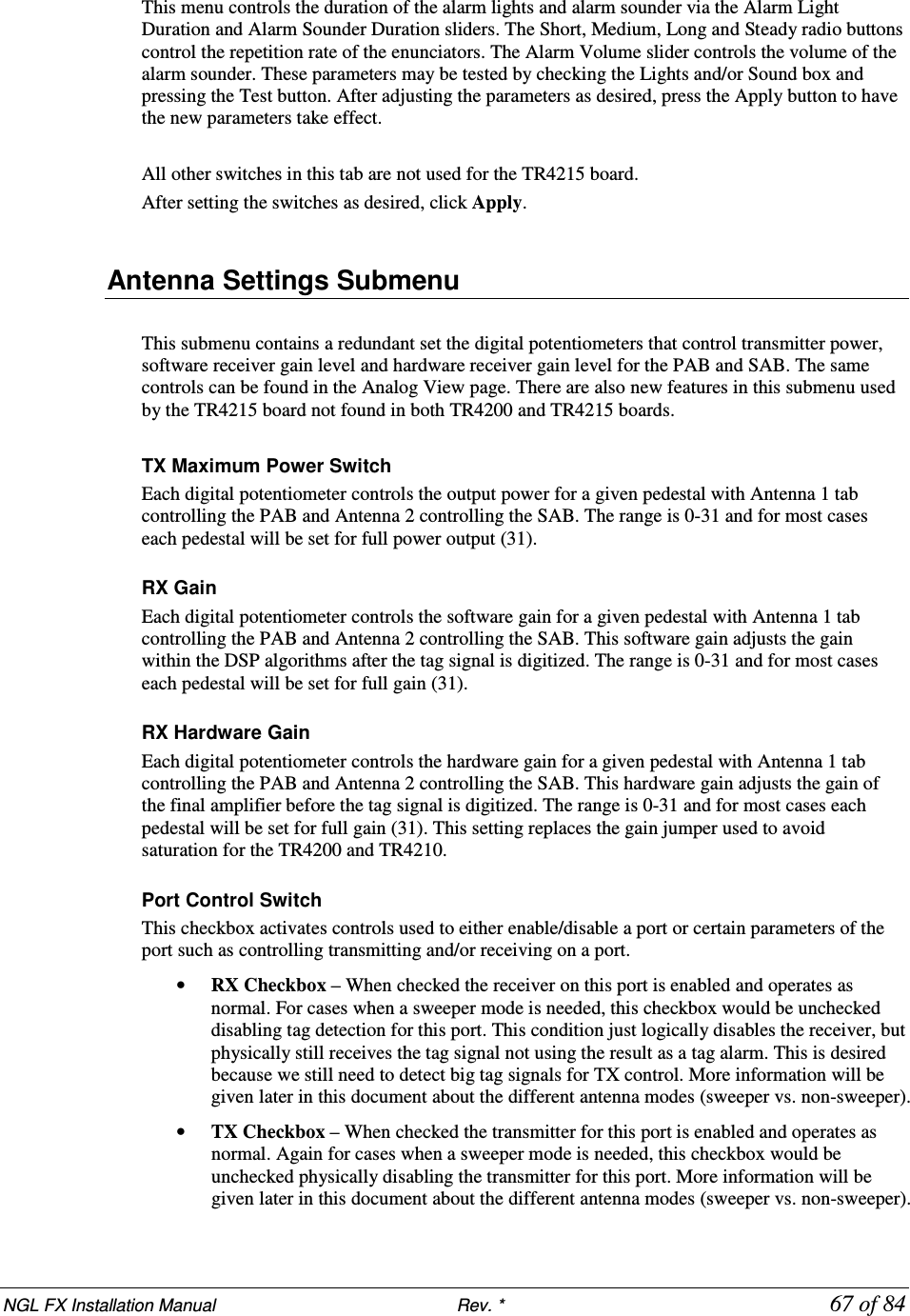
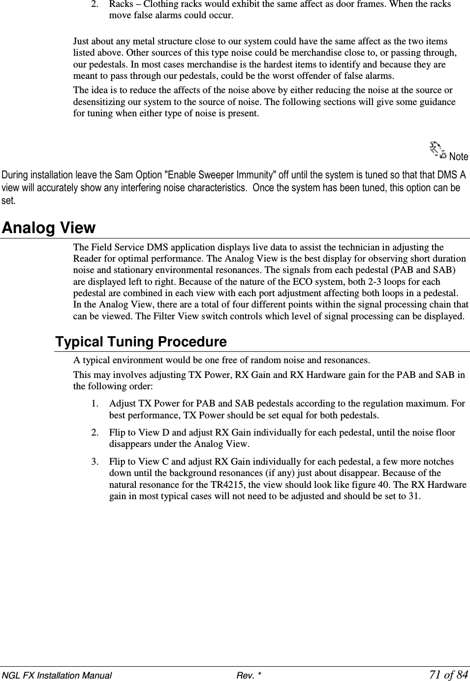
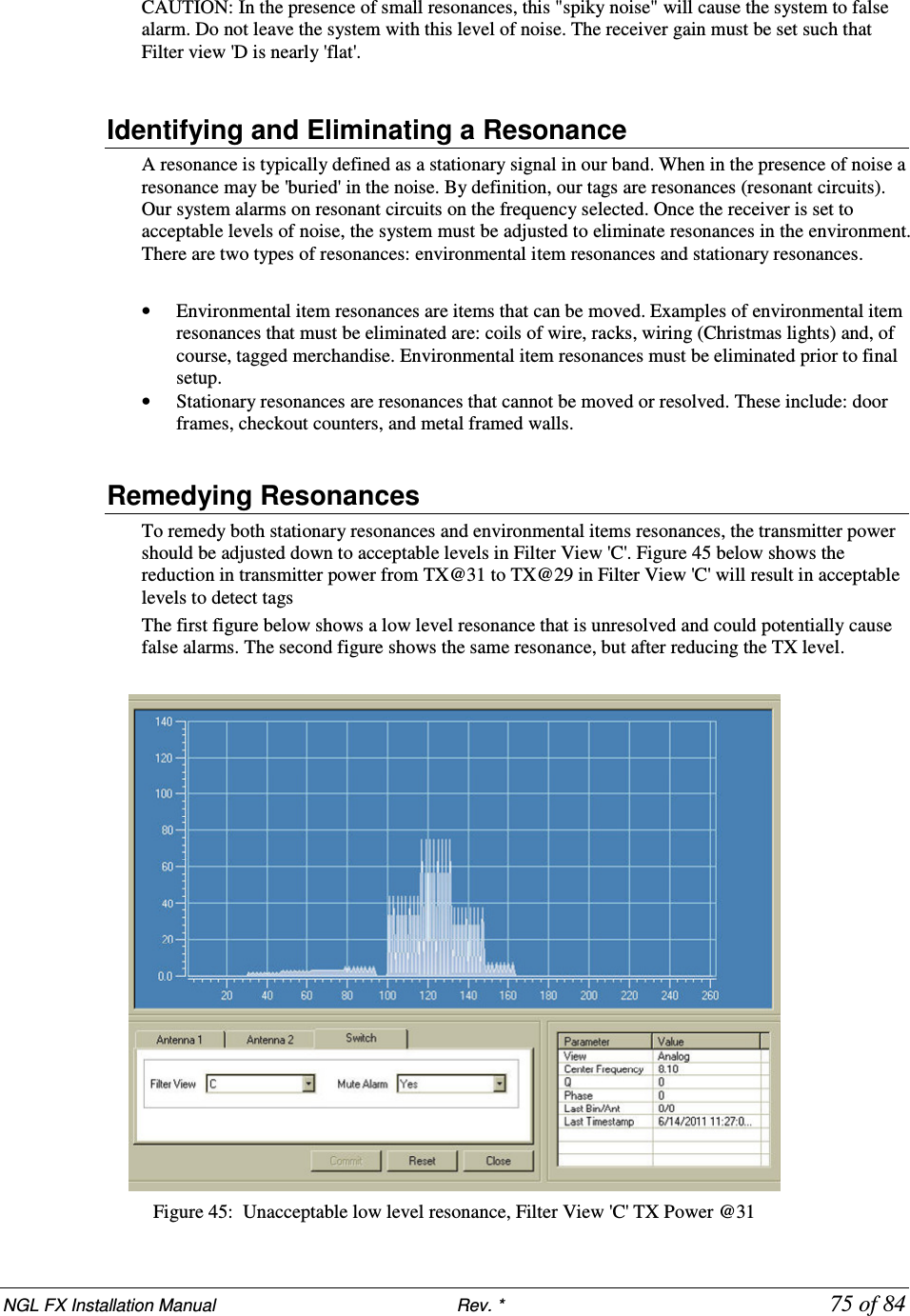
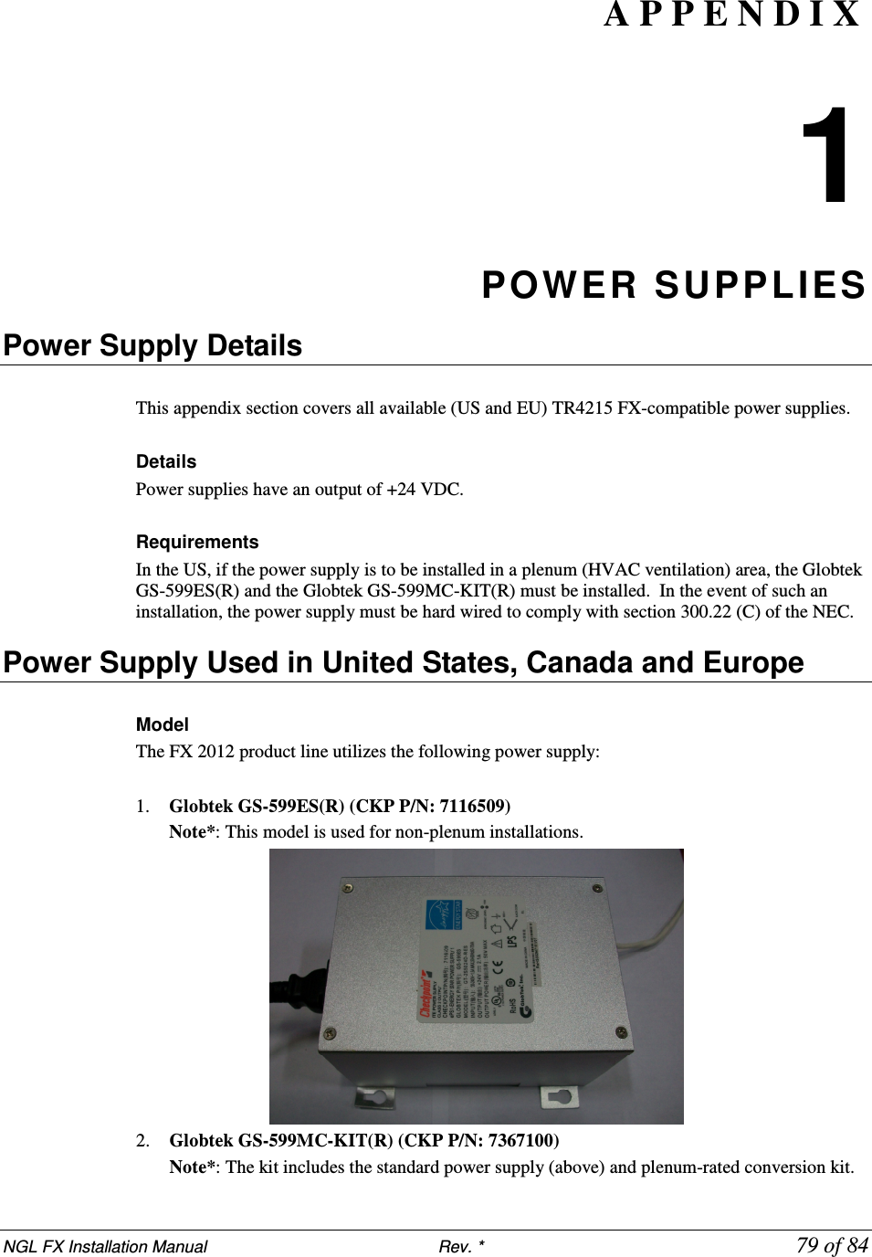
![NGL FX Installation Manual Rev. * 83 of 84 or 62125 Contractor Supplied n/a 1.9cm (¾”) PVC conduit, contractor supplied (used to house 15.1m (50’) transmission line in new installations before slab is poured.) Contractor Supplied T5002/1241 Thoro Waterplug Hydraulic Cement T5002, 10 lb can or Quickrete Fast Set Repair Mortar 1241 A P P E N D I X 4 IN TERA CTIONS FX System – Proximity to Deactivation Units The table below lists minimum distances where Counterpoint IX or D11 Deactivators can be located away from a FX system antenna. Deactivators do not affect the FX system performance. However, in 4 and 6 Mode, if any FX system is located inside a 1.8m [6ft] radius from the deactivator, false alarms may occur because the deactivator “sees” the system. It is not possible to slave a deactivator to a system with Strata-based electronics. Note*: The deactivator will intermittently alarm as it sees the FX pulsing, these alarms will occur on average every 30 seconds. Distance to FX System MODELS (all with pad) Up to 1.8m (6.0') > 1.8m (6.0') CP IX/D11 4 Mode Deactivator Phantoms (see note) No Interactions CP IX/D11 5 Mode No Interactions No Interactions](https://usermanual.wiki/Checkpoint-Systems/FX2012.FX-2012-Installation-Guide-Part-3/User-Guide-1801560-Page-39.png)
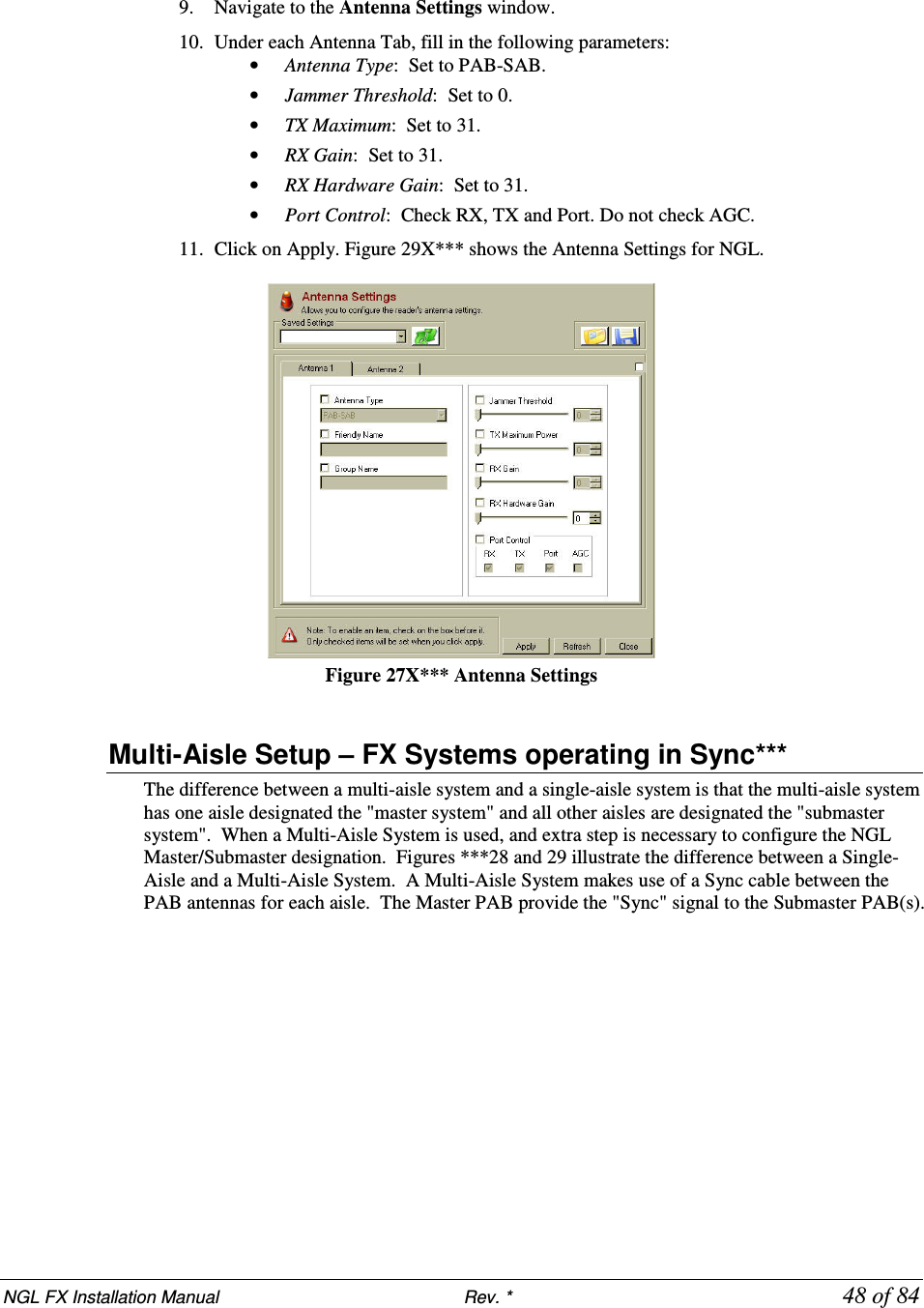
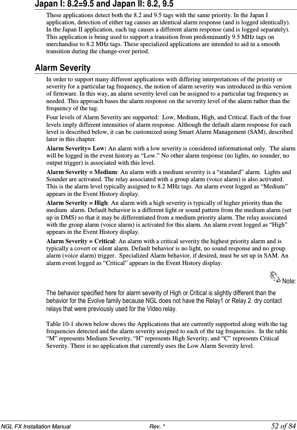
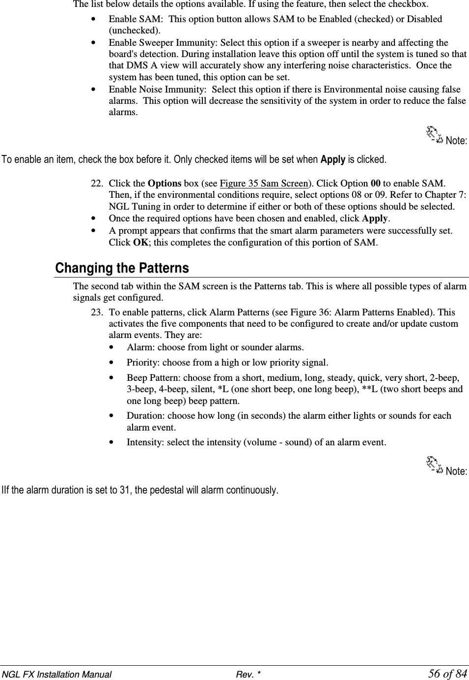
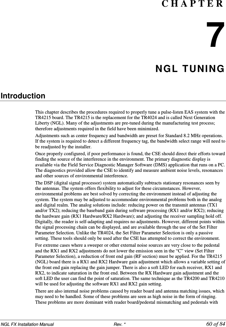
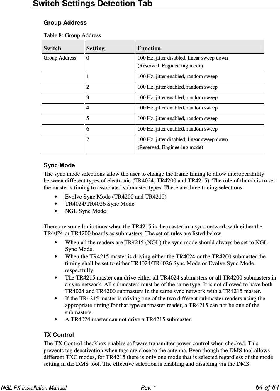
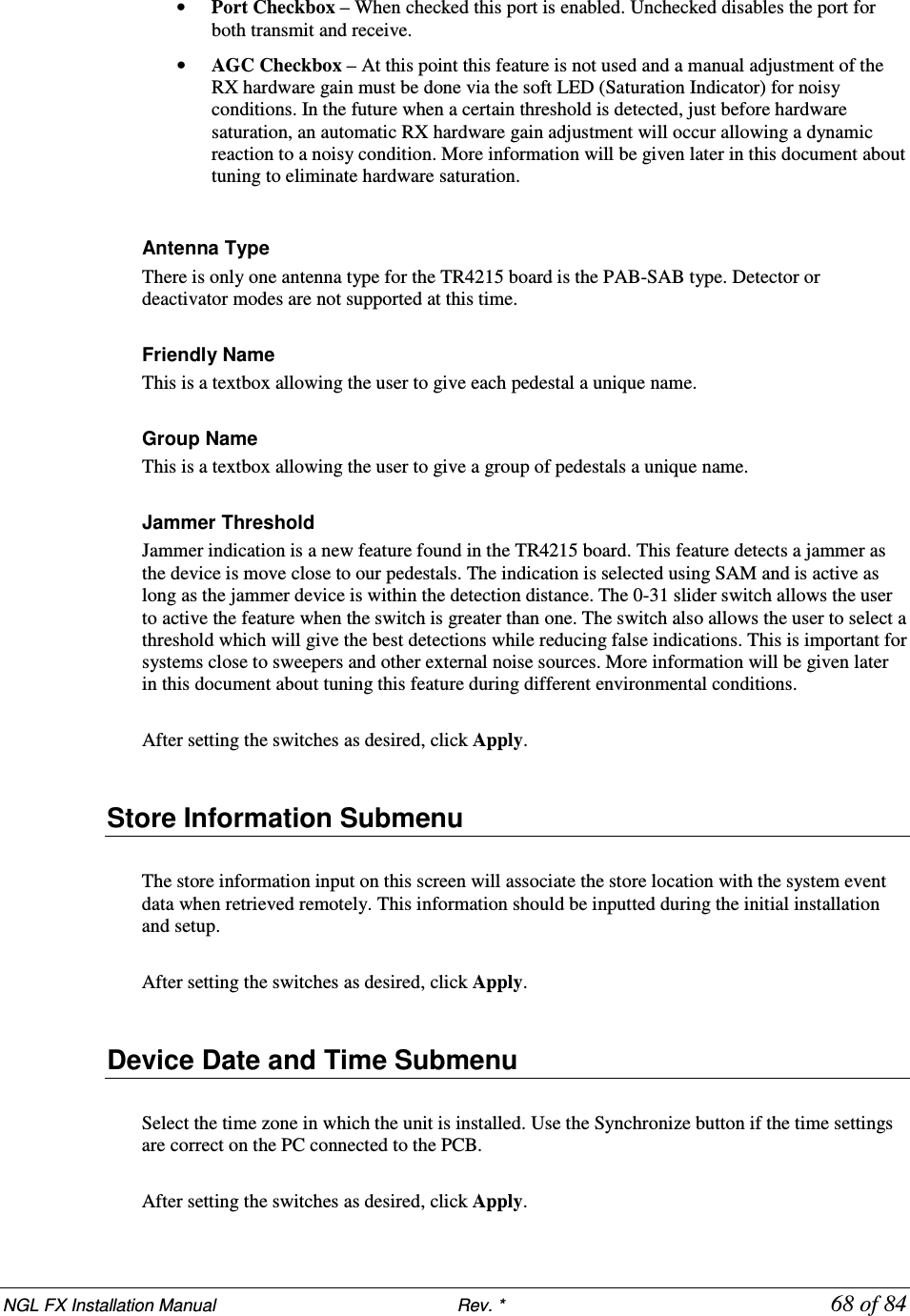
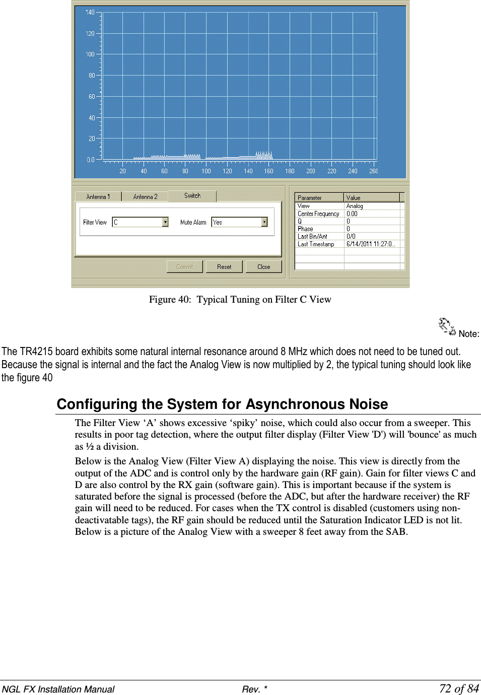
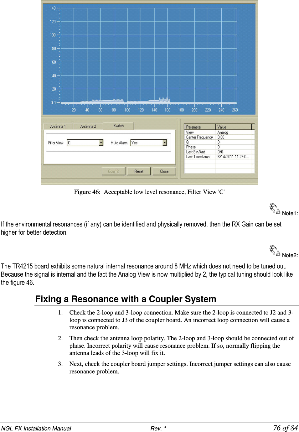
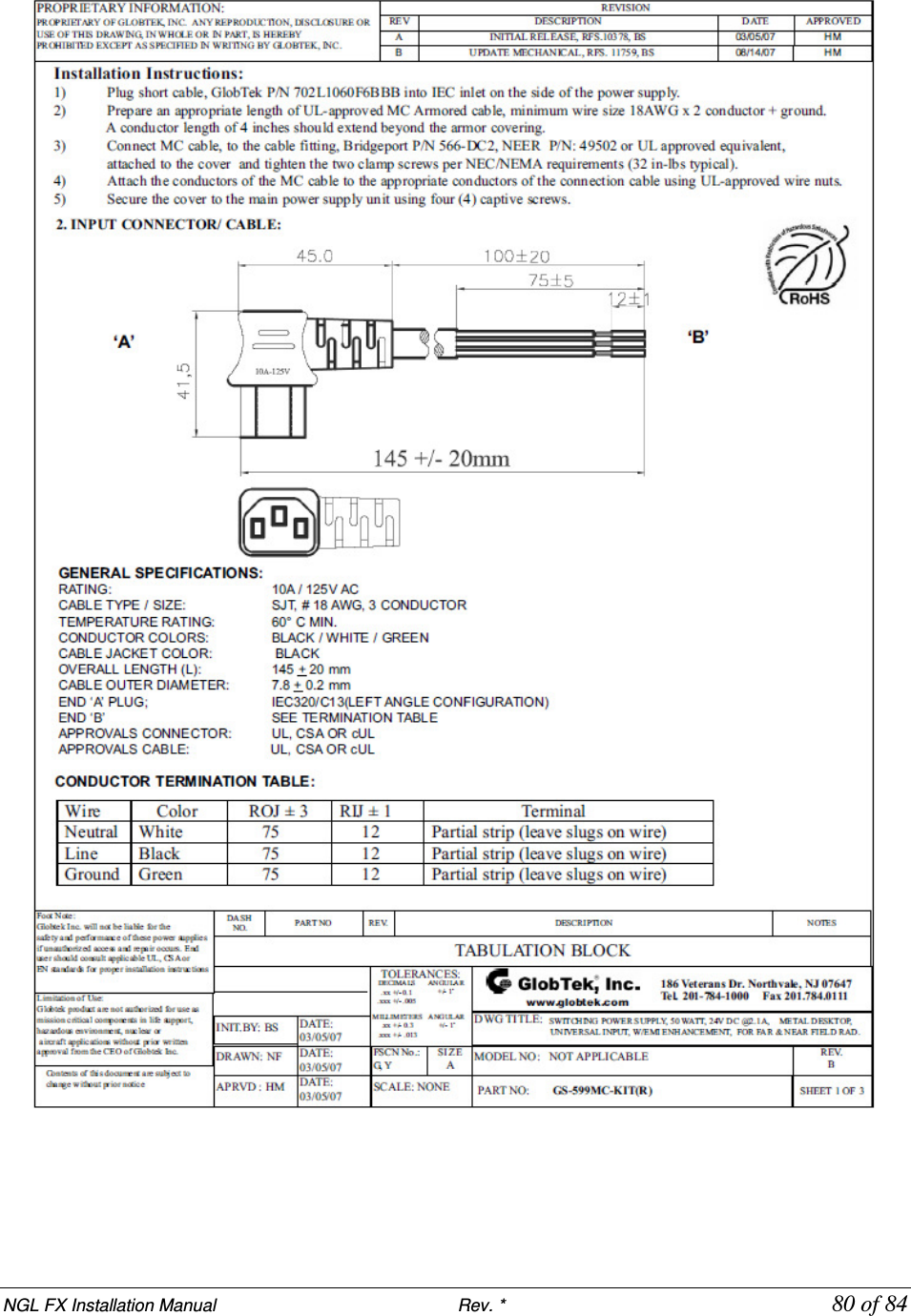
![NGL FX Installation Manual Rev. * 84 of 84 FX System – Proximity to Other Systems Please refer to the table below for details on how close systems can be to one another. Liberty FX to: Minimum Separation w/o Slaving Slave Options Any pedestal or floor system 12m [40 feet] Slave Pillar / Frame 4.6m [15 feet] None QS4000XT 4.6m [15 feet] None QS2000 4.6m [15 feet] None Signature 4.6m [15 feet] None Quicksilver 4.6m [15 feet] None QS6500 7.6m [25 feet] None QS45/55 7.6m [25 feet] None](https://usermanual.wiki/Checkpoint-Systems/FX2012.FX-2012-Installation-Guide-Part-3/User-Guide-1801560-Page-40.png)