Checkpoint Systems FX2012 Electronic Article Surveillance Detection System User Manual FX 2012 Installation Guide Part 3
Checkpoint Systems Inc Electronic Article Surveillance Detection System FX 2012 Installation Guide Part 3
Contents
- 1. FX 2012 Installation Guide Part 1
- 2. FX 2012 Installation Guide Part 2
- 3. FX 2012 Installation Guide Part 3
FX 2012 Installation Guide Part 3
NGL FX Installation Manual Rev. *
45 of 84
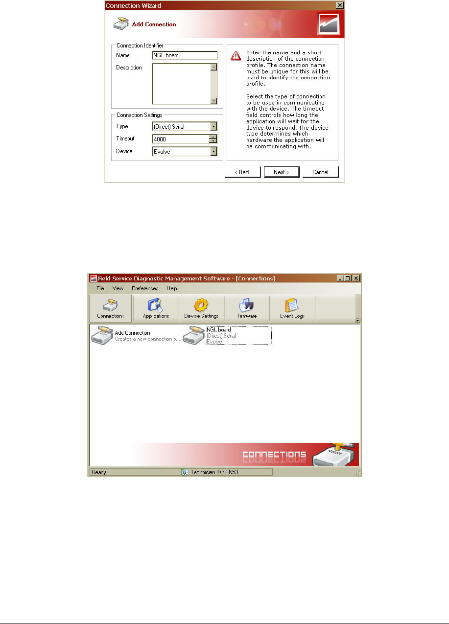
Figure X*** New Connection Setup
6. Click Next, a serial port selection window appears. Fill in the COM port parameters and
then click Next. The final connection summary window appears.
7. Click Finish to complete the new connection setup. A new icon titled “NGL board”
appears in the DMS Connections window (see Figure X*** below).
Figure 22X*** A New Connection Added
Configure PAB/SAB (coupler) operation mode
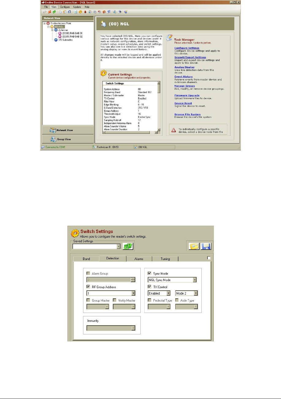
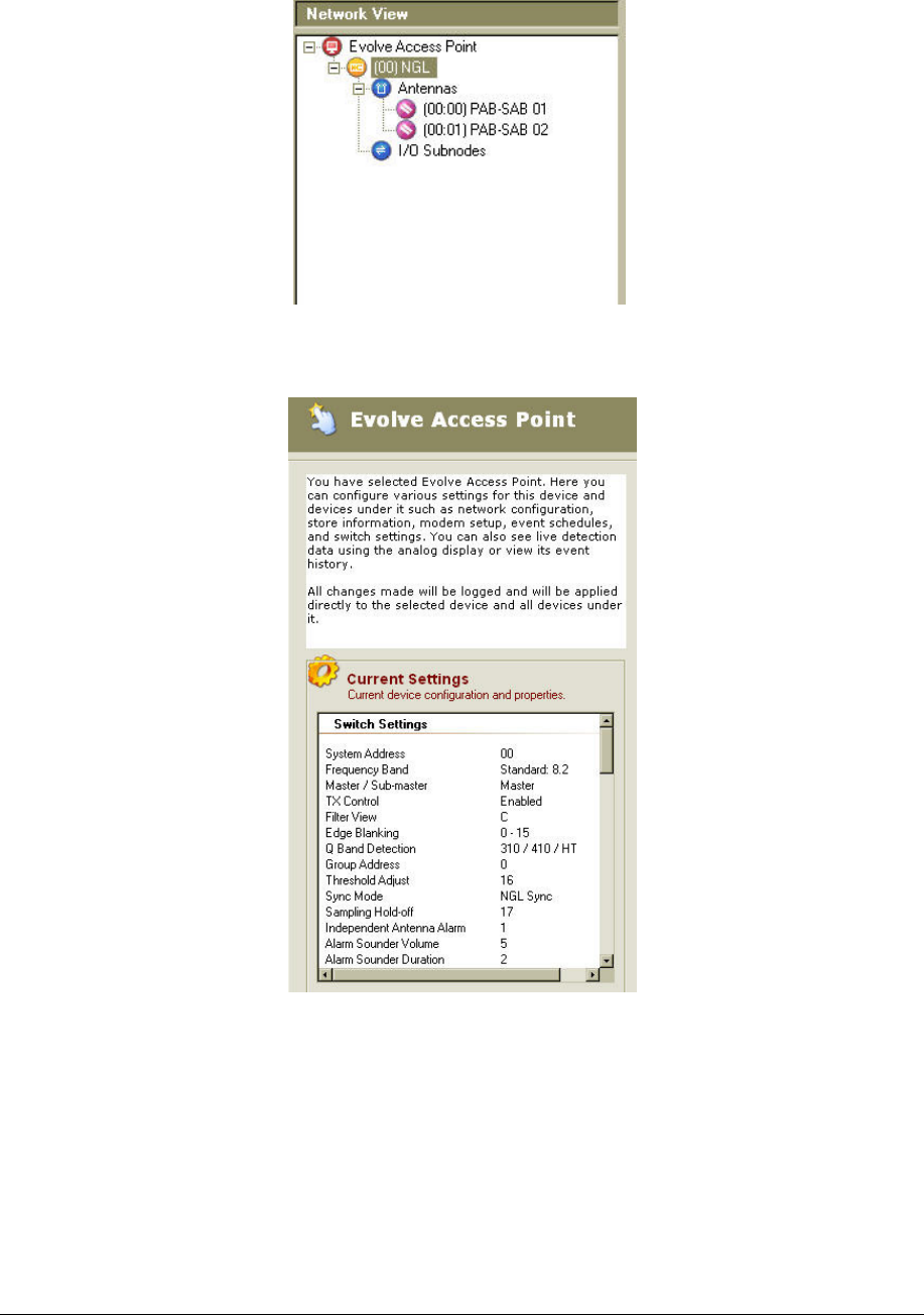
1. Using the DMS tool, connect to the TR4215 board. Figure 22X*** (23?) shows the
opening screen with the Network view expanded to show all devices.
NGL FX Installation Manual Rev. *
46 of 84
Figure 23X*** DMS Network and Task Manager View
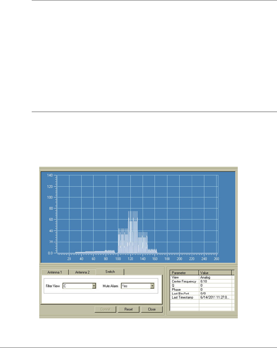
2. Navigate to the Switch Settings window.
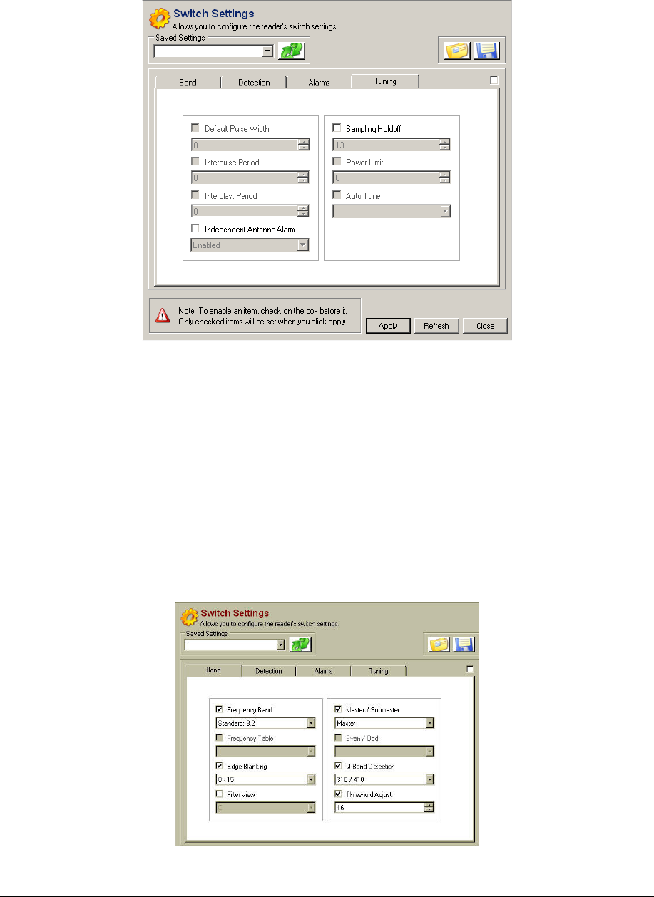
3. Under the Detection Tab, fill in the following parameters:
• RF Group Address: choose and address between 1 and 6. The address should
match any other PAB in the system (if Multi-Aisle is configured).
• Sync Mode: set to "NGL Sync Mode".
• TX Control: set to Enabled, Mode 2.
4. Click on Apply. Figure 26X*** shows the Detection parameters for NGL.
Figure 24 Detection Settings
5. Under the Tuning Tab, fill in the following parameters:
• Sampling Holdoff: Set to 13.
• Independent Antenna Alarm: Set to Enabled.
NGL FX Installation Manual Rev. *
47 of 84
6. Click Apply. Figure 27X*** shows the switch setting parameters under the Tuning tab.
Figure 25X*** Tuning Settings
7. Under the Band Tab, fill in the following parameters:
• Frequency Band: Set to the application required by the customer. For more
information about the choices, refer to ***"Application-Based Detection
Modes" section in this document.
• Edge Blanking: Set to 0-15.
• Master/Submaster: Set to "Master" for any Single-Aisle System. For Multi-
Aisle Systems, refer to the "Multi-Aisle Setup" section below for the appropriate
setting.
• Q Band Detection: Choose a setting based on the type of tags used by the
customer (Hard tag, 410, etc.).
• Threshold Adjust: Set to either 16 or 0.
8. Click on Apply. Figure 28X*** shows the Band tab parameters for NGL. ***
Figure 26X*** Band Settings
NGL FX Installation Manual Rev. *
48 of 84
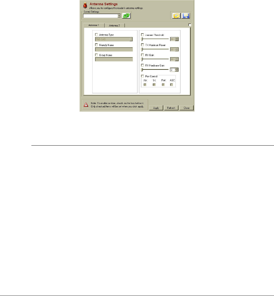
9. Navigate to the Antenna Settings window.
10. Under each Antenna Tab, fill in the following parameters:
• Antenna Type: Set to PAB-SAB.
• Jammer Threshold: Set to 0.
• TX Maximum: Set to 31.
• RX Gain: Set to 31.
• RX Hardware Gain: Set to 31.
• Port Control: Check RX, TX and Port. Do not check AGC.
11. Click on Apply. Figure 29X*** shows the Antenna Settings for NGL.
Figure 27X*** Antenna Settings
Multi-Aisle Setup – FX Systems operating in Sync***
The difference between a multi-aisle system and a single-aisle system is that the multi-aisle system
has one aisle designated the "master system" and all other aisles are designated the "submaster
system". When a Multi-Aisle System is used, and extra step is necessary to configure the NGL
Master/Submaster designation. Figures ***28 and 29 illustrate the difference between a Single-
Aisle and a Multi-Aisle System. A Multi-Aisle System makes use of a Sync cable between the
PAB antennas for each aisle. The Master PAB provide the "Sync" signal to the Submaster PAB(s).
NGL FX Installation Manual Rev. *
49 of 84
Figure 28 Single Aisle System
Figure 29 Multi-Aisle System
12. Move to the PAB of the PAB/SAB combination that you want to designate as master.
Attach a serial cable to the TR4215 board and using the DMS tool, connect to the board.
13. Navigate to the DMS Switch Settings window and click on the Band tab.
14. Select "Master" from the Master/Submaster selection box.
15. Click Apply. A success setting message box will come up. Click OK. Then, click
Disconnect to close down the DMS. Disconnect the serial cable from the TR4215 board.
16. Move to the PAB of a PAB/SAB combination that will be designated as SubMaster.
Attach a serial cable to the TR4215 board and using the DMS tool, connect to the board.
17. Navigate to the DMS Switch Settings window and click on the Band tab.
18. Select "Submaster" from the Master/Submaster selection box.
NGL FX Installation Manual Rev. *
50 of 84
19. Click Apply. A success setting message box will come up. Click OK. Then, click
Disconnect to close down the DMS. Disconnect the serial cable from the TR4215 board.
20. Repeat step 5 to 9 for each of the remaining the PAB antennas.
Application-Based Detection Modes
This section details the steps and options for device configuration with respect to specialized
application and SAM settings. Starting with Evolve Firmware version 3.60 and extending to the
Next Generation Liberty (NGL) system, a support structure has been put in place to support
application-based configuration and multi-band detection modes.
This section describes:
• Application mode concept and how it replaces earlier frequency band settings
• Extended alarming capability based on alarm severity levels
• Smart Alarm Management (SAM)
The Evolve system has been extended to provide comprehensive support for various dual-tag
detection modes. These modes allow the system to look for two different tag frequencies while
providing customized alarms for each.
The framework for this capability is a new Application-based configuration model introduced with
Evolve Waimea firmware (3.61). The approach is a change from previous Liberty versions and
will be described in detail in the following paragraphs. With the new approach, an application is
selected rather than a specific frequency band. Figure 30: Switch Settings Before and After shows
the difference between the previous Switch Settings Band menu and the new one.
Previous New
Figure 30: Switch Settings Before and After
Currently there are 10 supported applications, some supporting dual-tag detection while the
traditional applications still support a single tag. In the case where an application supports two
tags, there is a primary tag and a secondary tag. The primary tag is the most common one
NGL FX Installation Manual Rev. *
51 of 84
(typically 8.2 MHz) and the second tag is typically used for higher priority items or higher-cost
items. In the new menu shown, the application name includes the center frequency for the
supported tag(s).
Standard:8.2 and Library: 9.5
These are the standard applications and remain unchanged from the previous version of the
firmware. Each of these applications use a tag that falls within a single contiguous frequency range.
• Standard: 8.2 is the most common and most generic application.
• Library: 9.5 mode is used primarily in libraries.
Corral: 8.2, 9.0
This application is used in Toys-R-Us stores where the 8.2 MHz tags are placed on general
merchandise throughout the store and 9.0 MHz tags are placed on electronics located in a special
“Corral” area in the store.
Reverse Corral: 8.2, 9.0
This is used in Barnes & Noble and is similar to the Toys-R-Us implementation but the tag
frequencies are reversed. The 9.0 MHz tags are used for books throughout the store and the 8.2
MHz tags are used on other merchandise located in a “Corral” area.
Apparel: 8.2, 9.2
This application is used for stores where two levels of alarms are required to differentiate between
two priorities of merchandise. The system response is different (different light patterns or colors,
different sound patterns or voice alarm message) for each of the two tag types. The idea is to bring
special attention to the pedestal if the higher priority tag is detected.
Note:
Previously, this was known as the “9.0 tag band” or “Kohls.”
Pharma: 8.2, 7.2
This application is used primarily in stores containing a pharmacy. By design, this application has
a very low false alarm rate for the 7.2 MHz tag.
RazorKeeper: 8.2, 7.2
This application is similar in use to the Apparel application but uses the 8.2 MHz and 7.2 MHz
tags. The 7.2 MHz tags are placed inside razor keeper boxes and when detected cause an alarm
response that differs from the 8.2 MHz tag response (different light and sound patterns and/or
specialized voice message).
Immunity: 8.2
This application is similar to the Standard: 8.2 application in that only the 8.2 MHz tag is detected.
The unique feature of the Immunity: 8.2 application is that it is much more resistant to false
alarms caused by merchandise than the Standard: 8.2 application. This application is especially
useful in hardware stores where a large percentage of the merchandise is known to cause false
alarms. If false alarming due to merchandise is not a severe problem, it is better to use the
Standard: 8.2 application because it will detect 8.2MHz tags over a larger frequency range than the
Immunity: 8.2 application. Tags which vary in range +/- 3% or more from the center frequency of
8.2 MHz may not be detected in the Immunity: 8.2 application.

NGL FX Installation Manual Rev. *
52 of 84
Japan I: 8.2=9.5 and Japan II: 8.2, 9.5
These applications detect both the 8.2 and 9.5 tags with the same priority. In the Japan I
application, detection of either tag causes an identical alarm response (and is logged identically).
In the Japan II application, each tag causes a different alarm response (and is logged separately).
This application is being used to support a transition from predominantly 9.5 MHz tags on
merchandise to 8.2 MHz tags. These specialized applications are intended to aid in a smooth
transition during the change-over period.
Alarm Severity
In order to support many different applications with differing interpretations of the priority or
severity for a particular tag frequency, the notion of alarm severity was introduced in this version
of firmware. In this way, an alarm severity level can be assigned to a particular tag frequency as
needed. This approach bases the alarm response on the severity level of the alarm rather than the
frequency of the tag.
Four levels of Alarm Severity are supported: Low, Medium, High, and Critical. Each of the four
levels imply different intensities of alarm response. Although the default alarm response for each
level is described below, it can be customized using Smart Alarm Management (SAM), described
later in this chapter.
Alarm Severity= Low: An alarm with a low severity is considered informational only. The alarm
will be logged in the event history as “Low.” No other alarm response (no lights, no sounder, no
output trigger) is associated with this level.
Alarm Severity = Medium: An alarm with a medium severity is a “standard” alarm. Lights and
Sounder are activated. The relay associated with a group alarm (voice alarm) is also activated.
This is the alarm level typically assigned to 8.2 MHz tags. An alarm event logged as “Medium”
appears in the Event History display.
Alarm Severity = High: An alarm with a high severity is typically of higher priority than the
medium alarm. Default behavior is a different light or sound pattern from the medium alarm (set
up in DMS) so that it may be differentiated from a medium priority alarm. The relay associated
with the group alarm (voice alarm) is activated for this alarm. An alarm event logged as “High”
appears in the Event History display.
Alarm Severity = Critical: An alarm with a critical severity the highest priority alarm and is
typically a covert or silent alarm. Default behavior is no light, no sound response and no group
alarm (voice alarm) trigger. Specialized Alarm behavior, if desired, must be set up in SAM. An
alarm event logged as “Critical” appears in the Event History display.
Note:
The behavior specified here for alarm severity of High or Critical is slightly different than the
behavior for the Evolve family because NGL does not have the Relay1 or Relay 2 dry contact
relays that were previously used for the Video relay.
Table 10-1 shown below shows the Applications that are currently supported along with the tag
frequencies detected and the alarm severity assigned to each of the tag frequencies. In the table
“M” represents Medium Severity, “H” represents High Severity, and “C” represents Critical
Severity. There is no application that currently uses the Low Alarm Severity level.
NGL FX Installation Manual Rev. *
53 of 84
Table 4: Application Description
Tag
Frequency
Alarm
Severity
Tag
Frequency
Alarm
Severity
Application Name Primary Secondary
Standard: 8.2 8.2 M - -
Library: 9.5 9.5 M - -
Immunity: 8.2 8.2 M - -
Corral: 8.2, 9.0 8.2 M 9.0 H
Rev Corral: 9.0, 8.2 9.0 M 8.2 H
Apparel: 8.2, 9.2 8.2 M 9.2 H
Japan1: 8.2=9.5 8.2 M 9.5 M
Japan2: 8.2, 9.5 8.2 M 9.5 H
Pharma: 8.2, 7.2 8.2 M 7.2 C
RazorKeeper: 8.2, 7.2 8.2 M 7.2 H
Configuring SAM (Smart Alarm Management)
This chapter details the steps and options for configuration of the Smart Alarm Management
(SAM) system in DMS.
Note:
For information on installation and use of the DMS system, see the documents Field Service
Diagnostic Management
Navigating to the SAM Screen
Use DMS to connect to the desired TR4215 reader.
Note:
Although previous Liberty systems required the "TR4024/26" Device setting in the DMS
Connection Settings window, NGL uses the "Evolve" Device connection.
The Access page describes the current settings for the antennas in the group (shown in Figure 31:
Network View of Antenna Settings and Figure 32: List of Current Antenna Settings).
NGL FX Installation Manual Rev. *
54 of 84
.
Figure 31: Network View of Antenna Settings
Figure 32: List of Current Antenna Settings
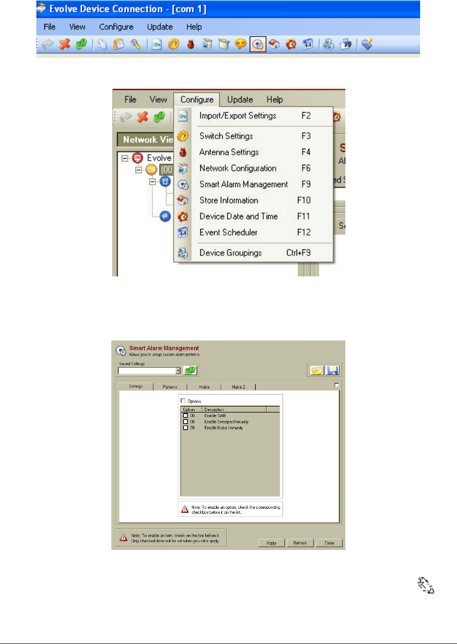
1. Navigate to the SAM screen by either clicking the SAM icon on the toolbar (shown in
Figure 33: DMS Toolbar with SAM Icon Highlighted), by selecting Configure > Smart
Alarm Management, or by click F9 (shown in Figure 34: Configure Menu in the DMS
System).
NGL FX Installation Manual Rev. *
55 of 84
Figure 33: DMS Toolbar with SAM Icon Highlighted
Figure 34: Configure Menu in the DMS System
21. Once the SAM screen appears (shown in Figure 35: SAM Screen), the device is ready for
configuration.
Figure 35: SAM Screen
Note
The pre-production version of the firmware only has the "Enable SAM" option available and not the other two.
NGL FX Installation Manual Rev. *
56 of 84
The list below details the options available. If using the feature, then select the checkbox.
• Enable SAM: This option button allows SAM to be Enabled (checked) or Disabled
(unchecked).
• Enable Sweeper Immunity: Select this option if a sweeper is nearby and affecting the
board's detection. During installation leave this option off until the system is tuned so that
that DMS A view will accurately show any interfering noise characteristics. Once the
system has been tuned, this option can be set.
• Enable Noise Immunity: Select this option if there is Environmental noise causing false
alarms. This option will decrease the sensitivity of the system in order to reduce the false
alarms.
Note:
To enable an item, check the box before it. Only checked items will be set when Apply is clicked.
22. Click the Options box (see Figure 35 Sam Screen). Click Option 00 to enable SAM.
Then, if the environmental conditions require, select options 08 or 09. Refer to Chapter 7:
NGL Tuning in order to determine if either or both of these options should be selected.
• Once the required options have been chosen and enabled, click Apply.
• A prompt appears that confirms that the smart alarm parameters were successfully set.
Click OK; this completes the configuration of this portion of SAM.
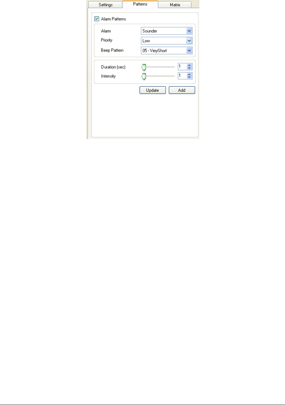
Changing the Patterns
The second tab within the SAM screen is the Patterns tab. This is where all possible types of alarm
signals get configured.
23. To enable patterns, click Alarm Patterns (see Figure 36: Alarm Patterns Enabled). This
activates the five components that need to be configured to create and/or update custom
alarm events. They are:
• Alarm: choose from light or sounder alarms.
• Priority: choose from a high or low priority signal.
• Beep Pattern: choose from a short, medium, long, steady, quick, very short, 2-beep,
3-beep, 4-beep, silent, *L (one short beep, one long beep), **L (two short beeps and
one long beep) beep pattern.
• Duration: choose how long (in seconds) the alarm either lights or sounds for each
alarm event.
• Intensity: select the intensity (volume - sound) of an alarm event.
Note:
IIf the alarm duration is set to 31, the pedestal will alarm continuously.
NGL FX Installation Manual Rev. *
57 of 84
Figure 36: Alarm Patterns Enabled
• At the bottom of the Alarm patterns menu are two buttons, Update and Add (see Figure
36: Alarm Patterns Enabled above).
• If Add is chosen, the new alarm pattern appears in the list of existing alarm pattern
(Light and Sounder - see Figure 37: Previously Established Alarm Patterns).
• If Update is chosen, this overwrites the existing alarm pattern to the new parameters.
• To Add, go through the pattern settings listed in step To enable patterns, click and select
the desired setting. Once the alarm pattern is configured to customer specifications, add
this specific alarm pattern as a new alarm by clicking Add.
• To Update, first highlight the existing alarm pattern that needs to be overwritten and go
through the pattern settings listed in step To enable patterns, click . Then click Update,
which will change the setting of the highlighted pattern and overwrite it.
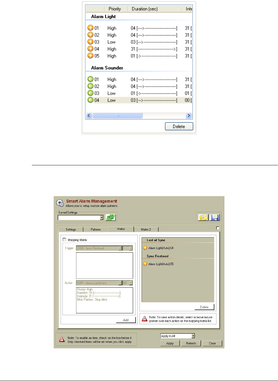
• An alarm pattern may also be deleted any time by highlighting it and clicking the Delete
button (see Figure 37: Previously Established Alarm Patterns).
NGL FX Installation Manual Rev. *
58 of 84
Figure 37: Previously Established Alarm Patterns
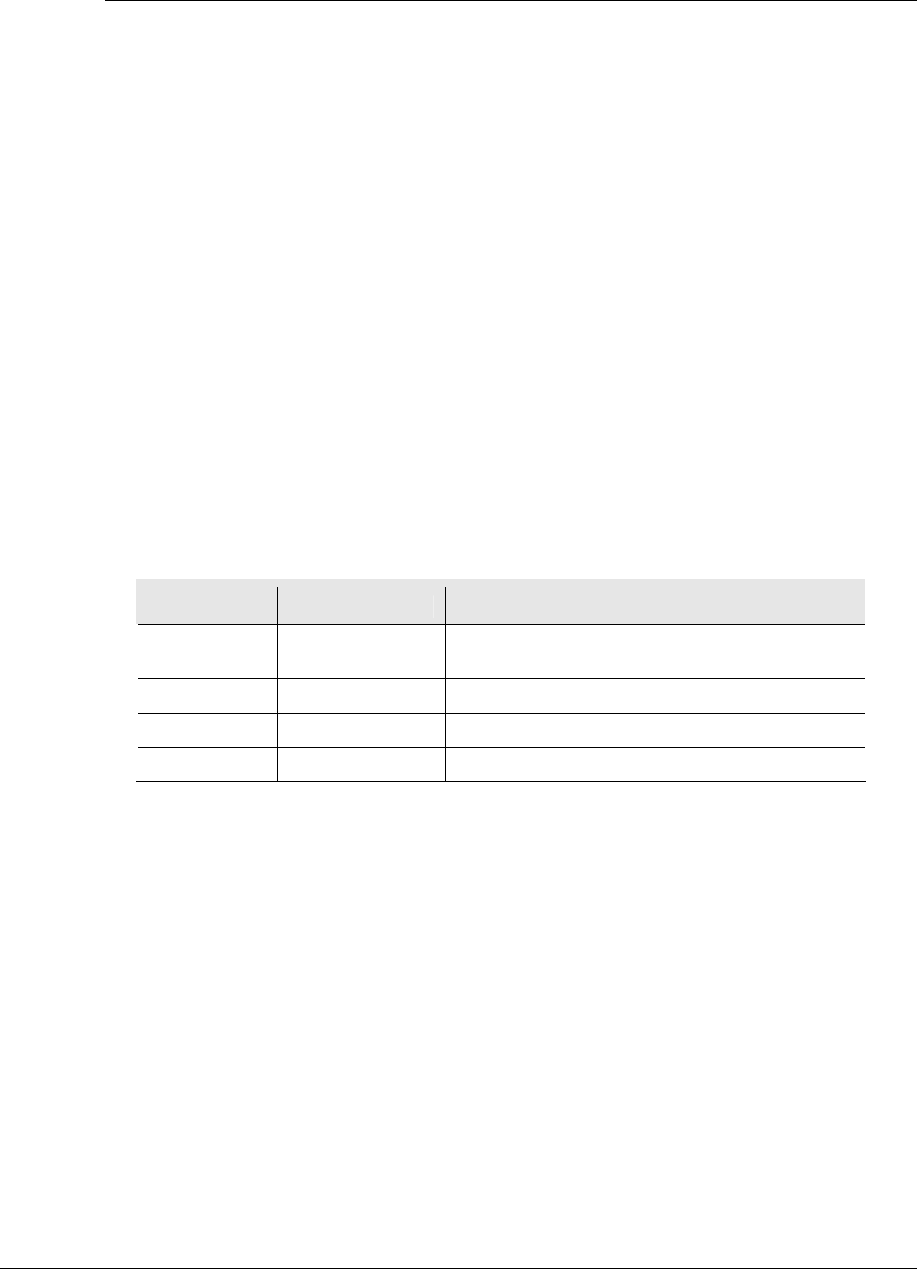
Changing the Matrix
Alarm patterns are matched to antenna triggers (see*** Figure 38: Matrix Tab) on the Matrix tab.
In the case of PAB/SAB systems, there will be two Matrix Tabs: "Matrix", "Matrix 2". The two
Matrix tabs allows the user to specify different behavior (light or sound) for the PAB and SAB
pedestals individually.
Figure 38: Matrix Tab

NGL FX Installation Manual Rev. *
59 of 84
24. To activate the Mapping Matrix menu, check the box directly to the left of Mapping
Matrix.
• From the Trigger drop down menu, select the event code that needs to be altered or set.
• Then, in the Action drop down menus, choose from a sounder alarm pattern, a light alarm
pattern, no action or output subnode in the left pull down.
• Once the alarm pattern has been selected, choose from the different custom patterns that
were established on the previous tab (see*** Figure 36: Alarm Patterns Enabled), which
are numbered in the right pull down.
• To finish coupling the selected alarm trigger with the custom alarm pattern, click Add.
The trigger appears on the right, where all alarm trigger and their alarm response patterns
are listed (see*** Figure 38: Matrix Tab).
• If necessary, an alarm trigger and the subsequent response can always be removed by
clicking Delete.
Note:
Selecting 00 in the drop down box will use the Light or Sounder settings that are under the Alarms tab in the Switch
settings menu.
Updating the System
Once the system is properly configured, click the Apply button. This loads all the new alarm
settings, patterns, and matrices into the Evolve system, updating it.

NGL FX Installation Manual Rev. *
60 of 84
C H A P T E R
7
NGL TUNING
Introduction
This chapter describes the procedures required to properly tune a pulse-listen EAS system with the
TR4215 board. The TR4215 is the replacement for the TR4024 and is called Next Generation
Liberty (NGL). Many of the adjustments are pre-tuned during the manufacturing test process;
therefore adjustments required in the field have been minimized.
Adjustments such as center frequency and bandwidth are preset for Standard 8.2 MHz operations.
If the system is required to detect a different frequency tag, the bandwidth select range will need to
be readjusted by the installer.
Once properly configured, if poor performance is found, the CSE should direct their efforts toward
finding the source of the interference in the environment. The primary diagnostic display is
available via the Field Service Diagnostic Manager Software (DMS) application that runs on a PC.
The diagnostics provided allow the CSE to identify and measure ambient noise levels, resonances
and other sources of environmental interference.
The DSP (digital signal processor) system automatically subtracts stationary resonances seen by
the antennas. The system offers flexibility to adjust for these circumstances. However,
environmental problems are best solved by correcting the environment instead of adjusting the
system. The system may be adjusted to accommodate environmental problems both in the analog
and digital realm. The analog solutions include: reducing power on the transmit antennas (TX1
and/or TX2); reducing the baseband gain during software processing (RX1 and/or RX2); reducing
the hardware gain (RX1 Hardware/RX2 Hardware); and adjusting the receiver sampling hold off.
Digitally, the reader is self-adapting and requires no adjustments. However, different points within
the signal processing chain can be displayed, and are available through the use of the Set Filter
Parameter Selection. Unlike the TR4024, the Set Filter Parameter Selection is only a passive
setting. These tools should only be used after the CSE has attempted to correct the environment.
For extreme cases where a sweeper or other external noise sources are very close to the pedestal
and the RX1 and RX2 adjustments do not lower the emission seen in the “C” view (Set Filter
Parameter Selection), a reduction of front end gain (RF section) must be applied. For the TR4215
(NGL) board there is a RX1 and RX2 Hardware gain adjustment which allows a variable setting of
the front end gain replacing the gain jumper. There is also a soft LED for each receiver, RX1 and
RX2, to indicate saturation in the front end. Between the RX Hardware gain adjustment and the
soft LED the user can find the point of saturation. The same technique as the TR4200 and TR4210
will be used for adjusting the software RX1 and RX2 gain setting.
There are also internal noise problems caused by reader board and antenna matching issues, which
may need to be handled. Some of these problems are seen as high noise in the form of ringing.
These problems are more dominant with reader board/pedestal mismatching and pedestals with

NGL FX Installation Manual Rev. *
61 of 84
low resonance close to the operating frequency range. These problems could be resolved by
increasing the gap (Sampling Holdoff) between transmit and receive cycles.
The TR4215 board does not support inter-pedestal, Ethernet or modem functionality. For this
reason all setting related to these feature will not be include in this document.
The Reader is powered by an external +24Vdc power supply. This power supply can power up to
a maximum of two antennas when these system have a reader driving each antenna.
The maximum power allowed within the systems would be limited by the +24V power supply,
which is 2.1A maximum.
The +24VDC is supplied by an external AC-DC converter listed below:
• Checkpoint Part 7116509 - Globetek 559-ES(R) -2.1A
An alternate can be used in Europe:
• Checkpoint Part 7210084 - EOS/Celetron Part LFZVC65SG24E -2.7A
• Second Source – Friwo Part 1825898 -2.2A
System Description
2 Loop/3 Loop
The TR4215 circuit board (PCB) is a transceiver typically using a pedestal consisting of a 3-loop,
2-loop and a 1-loop antenna. The PCB transmits and receivers on the 2-loop and 3-loop antenna of
the pedestal in which it is installed (primary pedestal) using just TX1/RX1 port. This is done by
splitting and combining this port via the passive A1096 coupler board. The 1-loop antenna of that
pedestal is used as a shield that is tied to ground. This technique provides the system with different
views of the detection field, allowing the system to improve detection by minimizing the holes
typically found at the crossbars of typical swept antennas.
During each frame, the transmitters (TX1 and TX2) emit thirty-two bursts of RF energy, four per
each of four frequency “bins” executed twice. A bin consists of two “receive” cycles and two
“blast” cycles; a “blast” is a transmit cycle followed by a “receive” cycle. The receive cycle
consists of a signal channel and a noise channel in that order. During the signal channel, the
system detects the tag ring down and during the noise channel, the system processes the noise. For
both channels the system does not transmit but only receives tag signal and ambient noise.
Processing the noise channel allows the system to establish the baseline noise level of the
environment for later comparison. The system then transmits or “pulses” the field and then
receives or “listens” for an echo of a tag signal.
A tag response need only be present on one of the antennas to cause an alarm. The switching
between antenna coil sets minimizes the size of detection holes at the null points of the RF field.
Although the TR4215 is considered a replacement for the TR4024 and TR4022 PCB’s, there are
still some compatibility issues between the two boards.
System Configuration
The TR4215 is different from previous pulse-listen transceivers as it does not use jumpers, DIP
switches, or potentiometers to modify its configuration. However, there are jumpers used to set the
basic frequency tuning (8.2 vs. 9.0) for the transmitter output and terminating the RS-485 for the
sync connection. All operating parameters for the TR4215 are controlled by the DMS software
application running on a PC that can only be connected to the Reader via serial Badge port (J48 of
Main). For detailed information, see the Field Service DMS User’s Guide.
The only configuration supported for the TR4215 is the ECO system using only one set of
electronics to drive two pedestals via passive A1096 couplers. This allows a typical aisle width of
up to 1.8m (6 feet).
NGL FX Installation Manual Rev. *
62 of 84
Switch Settings Band Tab
The TR4215 is different from previous pulse-listen transceivers as it does not use jumpers, DIP
switches, or potentiometers to modify its configuration. However, there are jumpers used to set the
basic frequency tuning (8.2 vs. 9.0) for the transmitter output and terminating the RS-485 for the
sync connection. All operating parameters for the TR4215 are controlled by the DMS software
application running on a PC that can only be connected to the Reader via serial Badge port (J48 of
Main). For detailed information, see the Field Service DMS User’s Guide.
The only configuration supported for the TR4215 is the ECO system using only one set of
electronics to drive two pedestals via passive A1096 couplers. This allows a typical aisle width of
up to 1.8m (6 feet).
System Address
Since there is no inter-pedestal communications or Ethernet for the TR4215 there is no needed for
these addresses.
Tag Band
For information about tag bands please refer to The section "Application-Based Detection Modes"
in Chapter 6.
Band Edge
The Phase Array/Reduce Pulse Width mode only transmits four different frequencies four times
consecutively therefore the Band Edge Selection setting 1-14 has no effect.
Table 5: Band Edge Selection
Switch Setting Function
Band Edge
Selection
1-14 No effect
0-7 High band bins eliminated
8-15 Low band bins eliminated
0-15 Full band detect
Filter View
The Filter View switch selects different digital signal processing views A, B, C, or D.
• Filter selection A: Raw Data only
• Filter selection B: Data following Peak Removal Filter
• Filter selection C: Data following Moving Average Filter
• Filter selection D: Data following Background Subtraction
As a rule of thumb, as you move progressively from View A through View D, noise is seen to be
suppressed, while resonance is enhanced. Stationary resonance is commonly identified according
to data signature, which is present in View C but absent in View D. Unlike the TR4024, these
views are passive and do not affect tag processing.
Master/Submaster/Repeater
The master/submaster mode is used to allow multiple sets of electronics to operate without
collisions when each set of electronics or pedestals are in close proximally of each other. For this
condition, one set of electronics will be set to master and a sync cable from the master shall be
connected to a second set of electronics which is set to submaster. The sync cable can be extended
by daisy chaining from each additional submaster in the network.
NGL FX Installation Manual Rev. *
63 of 84
The Repeater setting is used when many submasters are connected to the same master or the
distances between submasters is great. After daisy chaining the sync from board to board the sync
signal level or rise time could be reduced. For these cases enabling the Repeater on a submaster
will regenerate the sync pulse instead of just passively passing it on to the next submaster.
Table 6: Master/Submaster Sync
Switch Setting Function
Master/Slave/Set
up
Master Transceiver runs using on-board sync
Submaster Transceiver runs using external sync
Repeater Transceiver runs using external sync and is re generated
maintain sync signal quality.
Q Band Detection
The Q Band Detection switch selects No 'Q', HT (Hard Tag), 310 or 410 Q ranges.
Selecting No disables Q qualification. Any desired combination of 410, 310 or HT may be
selected to enable detection of the respective tags.
Table 7: Q Band Detection Switch
Switch Setting Function
Q Band Detection
Selection
No Q No limited Q range
HT (Hard Tag) Allows detection of tags with Q range 110-400
310 Allows detection of tags with Q range 80-110
310/HT Allows detection of tags with Q range 80-400
410 Allows detection of tags with Q range 50-85
410/HT Allows detection of tags with Q range 50-400
310/410 Allows detection of tags with Q range 50-110
310/410/HT Allows detection of tags with Q range 50-400
Note:
Selecting NO 'Q' increases the chance of phantom alarms.
Threshold Adjust
The Threshold Adjust setting should be set for either 0 or 16. In some earlier versions of firmware
this feature was not available.
After setting the switches as desired, click Apply.
NGL FX Installation Manual Rev. *
64 of 84
Switch Settings Detection Tab
Group Address
Table 8: Group Address
Switch Setting Function
Group Address 0 100 Hz, jitter disabled, linear sweep down
(Reserved, Engineering mode)
1 100 Hz, jitter enabled, random sweep
2 100 Hz, jitter enabled, random sweep
3 100 Hz, jitter enabled, random sweep
4 100 Hz, jitter enabled, random sweep
5 100 Hz, jitter enabled, random sweep
6 100 Hz, jitter enabled, random sweep
7 100 Hz, jitter disabled, linear sweep down
(Reserved, Engineering mode)
Sync Mode
The sync mode selections allow the user to change the frame timing to allow interoperability
between different types of electronic (TR4024, TR4200 and TR4215). The rule of thumb is to set
the master’s timing to associated submaster types. There are three timing selections:
• Evolve Sync Mode (TR4200 and TR4210)
• TR4024/TR4026 Sync Mode
• NGL Sync Mode
There are some limitations when the TR4215 is the master in a sync network with either the
TR4024 or TR4200 boards as submasters. The set of rules are listed below:
• When all the readers are TR4215 (NGL) the sync mode should always be set to NGL
Sync Mode.
• When the TR4215 master is driving either the TR4024 or the TR4200 submaster the
timing shall be set to either TR4024/TR4026 Sync Mode or Evolve Sync Mode
respectfully.
• The TR4215 master can drive either all TR4024 submasters or all TR4200 submasters in
a sync network. All submasters must be of the same type. It is not allowed to have both
TR4024 and TR4200 submasters in the same sync network with a TR4215 master.
• If the TR4215 master is driving one of the two different submaster readers using the
appropriate timing for that type submaster reader, a TR4215 can not be one of the
submasters.
• A TR4024 master can not drive a TR4215 submaster.
TX Control
The TX Control checkbox enables software transmitter power control when checked. This
prevents tag deactivation when tags are close to the antenna. Even though the DMS tool allows
different TXC modes, for TR4215 there is only one mode that is selected regardless of the mode
setting in the DMS tool. The effective selection is enabling and disabling via the DMS.
NGL FX Installation Manual Rev. *
65 of 84
All other switches in this tab are not used for the TR4215 board.
After setting the switches as desired, click Apply.
FX System Tuning and TR4215 Configuration
Tuning the FX system is consistent with the procedure, NGL Tuning, used for PX/QX systems.
During installation is the ideal time to reduce noise. Therefore, doing the proper site survey and
trial runs before embedding the components in concrete is essential for success. The differences
between the FX Antenna, PX/QX Pedestals and Deactivation Pads are briefly explained below.
TR4215 Board Configuration
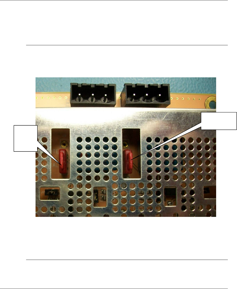
Figure 33 shows the red TX/RX port jumpers which selects between LOCAL (balanced output)
and REMOTE (unbalanced output).
Note*: By default the jumpers are in the REMOTE position and must be changed to the LOCAL
position for the FX installation. If this is not properly configured, a loss of detection will be
observed.
Figure 33: TR4215 Jumper Positions
Switch Settings Tuning Tab
Output
Jumper
set to
LOCAL
Ou
tput Jumper
set to LOCAL

NGL FX Installation Manual Rev. *
66 of 84
The set of switches under this tab are used to tune the system. Below is a description of each
switch.
Sample Holdoff
This setting adjusts the gap between the end of the transmit cycle and the time when the receiver is
enabled. The default setting of 17 (4.25us), but for the TR4215 the Sampling Holdoff should be
set to 13 (3.25us) and is used for both PX and QX pedestals.
In our system, this adjustment may be necessary due to the ringing that occurs after the transmitter
is disabled. This ringing could cause phantom alarms, and can be detected when viewing the DMS
Analog View “C”. By increasing the Sampling Holdoff setting, the effects of the ringing are
reduced. Care should be taken when increasing this gap to ensure a minimum loss of detection.
The range the DMS Sampling Holdoff setting is 1-31, which equates to a gap of 0.25
microseconds to 7.75 microseconds.
Sample Holdoff Setting
The default Sample Holdoff for the TR4215 is 17. For most of the TR4215 installation this could
be reduced to 13-14, but because of the nature of the FX System Antenna it would probably stay at
the default of 17. As with all installations, some experimentation can be done to find the optimal
setting. This is done by using the default setting of 17 and reducing the setting until an
unacceptable resonant appears. At this point increase the setting to the last value before the
resonance appeared.
Independent Antenna Alarm Switch
The Independent Antenna Alarm is used to either configure the system to simultaneously transmit
on both ports (TX1and TX2) if disabled or alternate transmission on both ports if enabled. For an
ECO system it has been found when both pedestals transmit at the same time, false alarms could
occur on the adjacent pedestal when a tag is introduced to the other pedestal. This is unacceptable
for an Inlane System.
Since the TR4215 only supports the ECO Mode (PAB/SAB configuration) this switch must
always be enabled.
After setting the switches as desired, click Apply.
Independent Antenna Alarm Setting
The Independent Antenna Alarm setting is used to eliminate the chance in a PAB/SAB
configuration to receive the wrong or redundant alarm event record for a given alarm. This occurs
because of the nature of the ECO system allowing one RX/TX port to drive both 2 and 3 loops in a
pedestal. For the FX System each RX/TX port will drive an independent loop antenna. For this
case and the nature of a floor system, a redundant alarm is not critical. For this reason this
setting should be set to disabled.
Switch Settings Alarm Tab

NGL FX Installation Manual Rev. *
67 of 84
This menu controls the duration of the alarm lights and alarm sounder via the Alarm Light
Duration and Alarm Sounder Duration sliders. The Short, Medium, Long and Steady radio buttons
control the repetition rate of the enunciators. The Alarm Volume slider controls the volume of the
alarm sounder. These parameters may be tested by checking the Lights and/or Sound box and
pressing the Test button. After adjusting the parameters as desired, press the Apply button to have
the new parameters take effect.
All other switches in this tab are not used for the TR4215 board.
After setting the switches as desired, click Apply.
Antenna Settings Submenu
This submenu contains a redundant set the digital potentiometers that control transmitter power,
software receiver gain level and hardware receiver gain level for the PAB and SAB. The same
controls can be found in the Analog View page. There are also new features in this submenu used
by the TR4215 board not found in both TR4200 and TR4215 boards.
TX Maximum Power Switch
Each digital potentiometer controls the output power for a given pedestal with Antenna 1 tab
controlling the PAB and Antenna 2 controlling the SAB. The range is 0-31 and for most cases
each pedestal will be set for full power output (31).
RX Gain
Each digital potentiometer controls the software gain for a given pedestal with Antenna 1 tab
controlling the PAB and Antenna 2 controlling the SAB. This software gain adjusts the gain
within the DSP algorithms after the tag signal is digitized. The range is 0-31 and for most cases
each pedestal will be set for full gain (31).
RX Hardware Gain
Each digital potentiometer controls the hardware gain for a given pedestal with Antenna 1 tab
controlling the PAB and Antenna 2 controlling the SAB. This hardware gain adjusts the gain of
the final amplifier before the tag signal is digitized. The range is 0-31 and for most cases each
pedestal will be set for full gain (31). This setting replaces the gain jumper used to avoid
saturation for the TR4200 and TR4210.
Port Control Switch
This checkbox activates controls used to either enable/disable a port or certain parameters of the
port such as controlling transmitting and/or receiving on a port.
• RX Checkbox – When checked the receiver on this port is enabled and operates as
normal. For cases when a sweeper mode is needed, this checkbox would be unchecked
disabling tag detection for this port. This condition just logically disables the receiver, but
physically still receives the tag signal not using the result as a tag alarm. This is desired
because we still need to detect big tag signals for TX control. More information will be
given later in this document about the different antenna modes (sweeper vs. non-sweeper).
• TX Checkbox – When checked the transmitter for this port is enabled and operates as
normal. Again for cases when a sweeper mode is needed, this checkbox would be
unchecked physically disabling the transmitter for this port. More information will be
given later in this document about the different antenna modes (sweeper vs. non-sweeper).

NGL FX Installation Manual Rev. *
68 of 84
• Port Checkbox – When checked this port is enabled. Unchecked disables the port for
both transmit and receive.
• AGC Checkbox – At this point this feature is not used and a manual adjustment of the
RX hardware gain must be done via the soft LED (Saturation Indicator) for noisy
conditions. In the future when a certain threshold is detected, just before hardware
saturation, an automatic RX hardware gain adjustment will occur allowing a dynamic
reaction to a noisy condition. More information will be given later in this document about
tuning to eliminate hardware saturation.
Antenna Type
There is only one antenna type for the TR4215 board is the PAB-SAB type. Detector or
deactivator modes are not supported at this time.
Friendly Name
This is a textbox allowing the user to give each pedestal a unique name.
Group Name
This is a textbox allowing the user to give a group of pedestals a unique name.
Jammer Threshold
Jammer indication is a new feature found in the TR4215 board. This feature detects a jammer as
the device is move close to our pedestals. The indication is selected using SAM and is active as
long as the jammer device is within the detection distance. The 0-31 slider switch allows the user
to active the feature when the switch is greater than one. The switch also allows the user to select a
threshold which will give the best detections while reducing false indications. This is important for
systems close to sweepers and other external noise sources. More information will be given later
in this document about tuning this feature during different environmental conditions.
After setting the switches as desired, click Apply.
Store Information Submenu
The store information input on this screen will associate the store location with the system event
data when retrieved remotely. This information should be inputted during the initial installation
and setup.
After setting the switches as desired, click Apply.
Device Date and Time Submenu
Select the time zone in which the unit is installed. Use the Synchronize button if the time settings
are correct on the PC connected to the PCB.
After setting the switches as desired, click Apply.

NGL FX Installation Manual Rev. *
69 of 84
Smart Alarm Management (SAM) Submenu
The TR4215 board supports the basic options, but of course only supports the limited feature set
for provide by this board. For information about SAM please refer to section on Configuring SAM
in Chapter 6.
LED Definitions
System Status Indicators (DS1-DS3, DS9-DS12)
DS1 (Green) - DSP Sync
Heart beat. Indicates the firmware is running correctly when green.
DS2 (Green) - Inter-pedestal Transmit Enabled
This LED indicates the system is transmitting serial data on the inter-pedestal network, which is
not used for the TR4215.
DS3 (Green) and DS9 (Yellow)
See Sync Indicators below.
DS9 (Yellow) - Inter-pedestal Receive Data is Present in FPGA FIFO
Excess data communication is present. System might be slow. This LED is not used for the
TR4215.
DS10 (Red) - FPGA Interrupt Pending
When this LED is lit, an interrupt has been issued by the FPGA indicating either Inter-pedestal or
IDC data is present. The LED will turn off when the interrupt is handled by the Blackfin. This is
popularly known as the ‘Red LED of death’ as the board is non-recoverable in the field; only an
experienced technician might recover the board.
DS11 (Red) - FPGA Load
This red LED indicates the program status of the FPGA device. When this is lit, the FPGA is
being programmed. After the programming is complete, the LED should be off.
DS12 (Green) - Writing to Flash File System
This LED is lit when the system is writing data to the flash file system. This is a good indication
when a flash write is completed.
Internal/External Sync Indicators (DS1, DS9)
This applies to Phase 2 and above.
External loss of sync indication could be setup in SAM allowing the user flexibility in setting up a
unique indication.
NGL FX Installation Manual Rev. *
70 of 84
Table 9: Sync Indicators
Board
Selection
External
Sync
Source
DS3
(Master)
Green
DS9
(Submaster)
Yellow Pedestal Lights Description
Master Absent On Off - Self generating sync, no external
sync pulse received. (Normal)
Master Present Off Blink - Master is receiving an external
sync pulse. When this occurs the
master becomes a submaster.
(Abnormal)
Submaster Absent Blink Blink On
(This is the default
indication and can be
changed using SAM)
Submaster either lost or never
received external sync pulse.
Report this error by System Event.
(Error)
Submaster Present Off On - Submaster is receiving an external
sync pulse. (Normal)
DC Power Indicator (DS13)
DS13 on the Main PCB will illuminate when 24VDC is applied to the board at terminals J18 or
J31.
Noise Sources
There are generally two different types of noise sources our systems can encounter; asynchronous
and synchronous.
Asynchronous noise is random in nature and is found through out the frame (signal and noise
channel) when certain devices are at close proximally to our system. These sources could reduce
detection and in some cases cause false alarming. Asynchronous noise sources could be the
following:
1. CW Sweeper – These devices sweep through out detection band causing loss of detection
and false alarming. They usually have a constant linear sweep rate (100Hz to 200Hz)
with a certain high and low frequency range and a constant signal level.
2. Spiky Noise – This is usually from automatic door motors, (broken) lighting ballasts and
other pulse listening systems not synchronize to our system.
Synchronous noise is associated with items in close proximally to our system which resonate
during our transmission cycle and look like a tag ring down to our system. These items are more
of a false alarm threat when compared to asynchronous noise especially if the item is moving.
They could also affect detection because of the complex mixing of the intended tag signal and
offending resonance. Synchronous noise sources could be the following:
1. Automatic Door Frames – In some cases metal doors will resonate and cause an emission
much like a tag ring down. When the door opens and closes, the background subtraction
feature could be defeated causing false alarms.

NGL FX Installation Manual Rev. *
71 of 84
2. Racks – Clothing racks would exhibit the same affect as door frames. When the racks
move false alarms could occur.
Just about any metal structure close to our system could have the same affect as the two items
listed above. Other sources of this type noise could be merchandise close to, or passing through,
our pedestals. In most cases merchandise is the hardest items to identify and because they are
meant to pass through our pedestals, could be the worst offender of false alarms.
The idea is to reduce the affects of the noise above by either reducing the noise at the source or
desensitizing our system to the source of noise. The following sections will give some guidance
for tuning when either type of noise is present.
Note
During installation leave the Sam Option "Enable Sweeper Immunity" off until the system is tuned so that that DMS A
view will accurately show any interfering noise characteristics. Once the system has been tuned, this option can be
set.
Analog View
The Field Service DMS application displays live data to assist the technician in adjusting the
Reader for optimal performance. The Analog View is the best display for observing short duration
noise and stationary environmental resonances. The signals from each pedestal (PAB and SAB)
are displayed left to right. Because of the nature of the ECO system, both 2-3 loops for each
pedestal are combined in each view with each port adjustment affecting both loops in a pedestal.
In the Analog View, there are a total of four different points within the signal processing chain that
can be viewed. The Filter View switch controls which level of signal processing can be displayed.
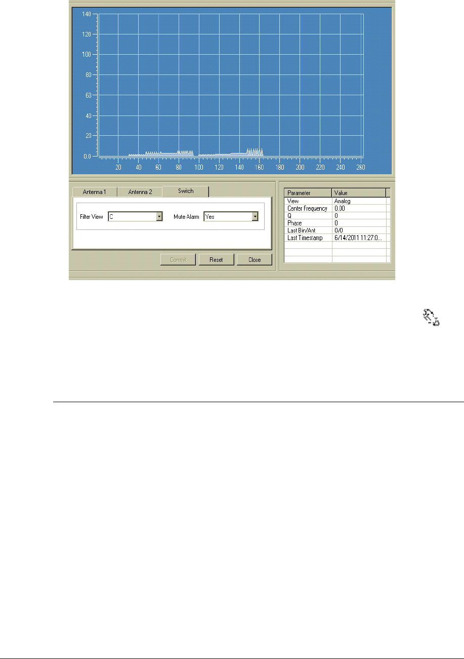
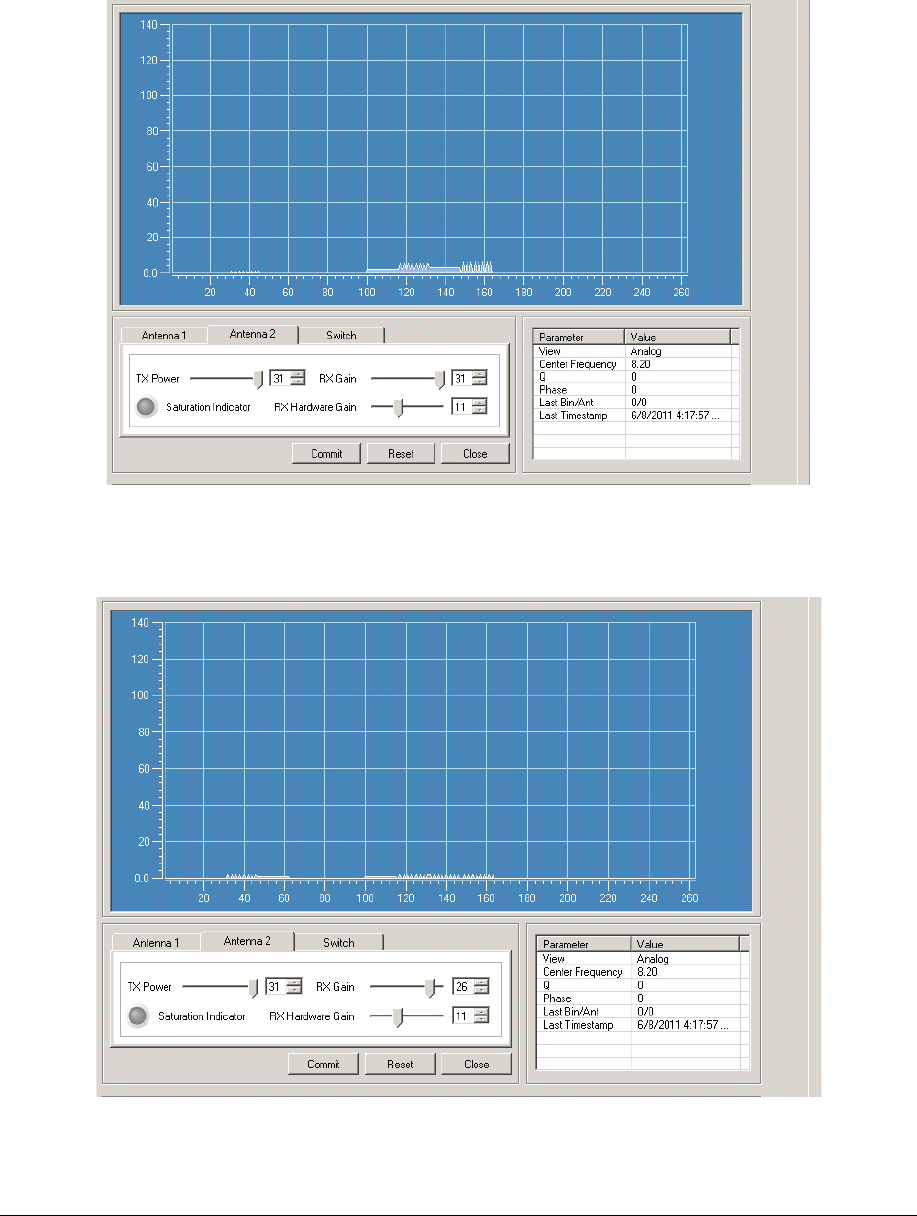
Typical Tuning Procedure
A typical environment would be one free of random noise and resonances.
This may involves adjusting TX Power, RX Gain and RX Hardware gain for the PAB and SAB in
the following order:
1. Adjust TX Power for PAB and SAB pedestals according to the regulation maximum. For
best performance, TX Power should be set equal for both pedestals.
2. Flip to View D and adjust RX Gain individually for each pedestal, until the noise floor
disappears under the Analog View.
3. Flip to View C and adjust RX Gain individually for each pedestal, a few more notches
down until the background resonances (if any) just about disappear. Because of the
natural resonance for the TR4215, the view should look like figure 40. The RX Hardware
gain in most typical cases will not need to be adjusted and should be set to 31.
NGL FX Installation Manual Rev. *
72 of 84
Figure 40: Typical Tuning on Filter C View
Note:
The TR4215 board exhibits some natural internal resonance around 8 MHz which does not need to be tuned out.
Because the signal is internal and the fact the Analog View is now multiplied by 2, the typical tuning should look like
the figure 40
Configuring the System for Asynchronous Noise
The Filter View ‘A’ shows excessive ‘spiky’ noise, which could also occur from a sweeper. This
results in poor tag detection, where the output filter display (Filter View 'D') will 'bounce' as much
as ½ a division.
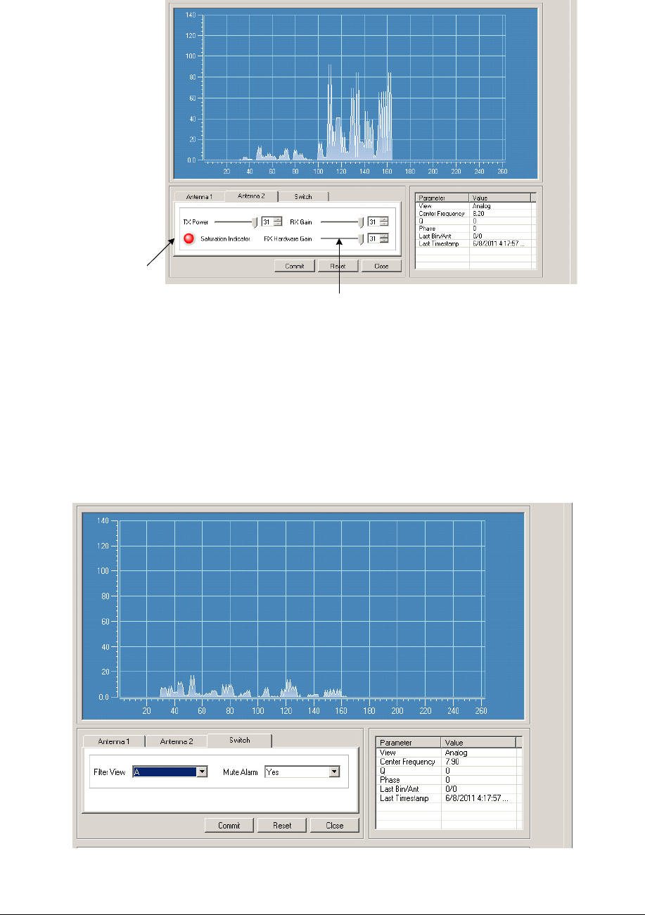
Below is the Analog View (Filter View A) displaying the noise. This view is directly from the
output of the ADC and is control only by the hardware gain (RF gain). Gain for filter views C and
D are also control by the RX gain (software gain). This is important because if the system is
saturated before the signal is processed (before the ADC, but after the hardware receiver) the RF
gain will need to be reduced. For cases when the TX control is disabled (customers using non-
deactivatable tags), the RF gain should be reduced until the Saturation Indicator LED is not lit.
Below is a picture of the Analog View with a sweeper 8 feet away from the SAB.
NGL FX Installation Manual Rev. *
73 of 84
Active Saturation
Indication LED
RX Hardware Gain Control
Figure 41: Noise on Filter A View RX and RX Hardware Gain @ 31
If the TX Control is enabled using the Saturation Indicator is not enough and addition reduction of
the RF gain will be necessary. For this condition follow the steps below for reducing the RF gain.
1. Observe the signal level in View A for about 15-30 seconds and make note of the highest
level during this period (peak response).
2. Reduce the RF gain until the peak response is only about one division. Below is a picture
after the adjustment.
Figure 42: Noise on Filter View A After RF Gain Tuning
NGL FX Installation Manual Rev. *
74 of 84
3. After the RF gain is adjusted, observe Filter View D for about 15-30 seconds and note the
peak response during this period. Below is a picture before adjusting the RX gain.
Figure 43: Noise on Filter View D before RX Gain Tuning
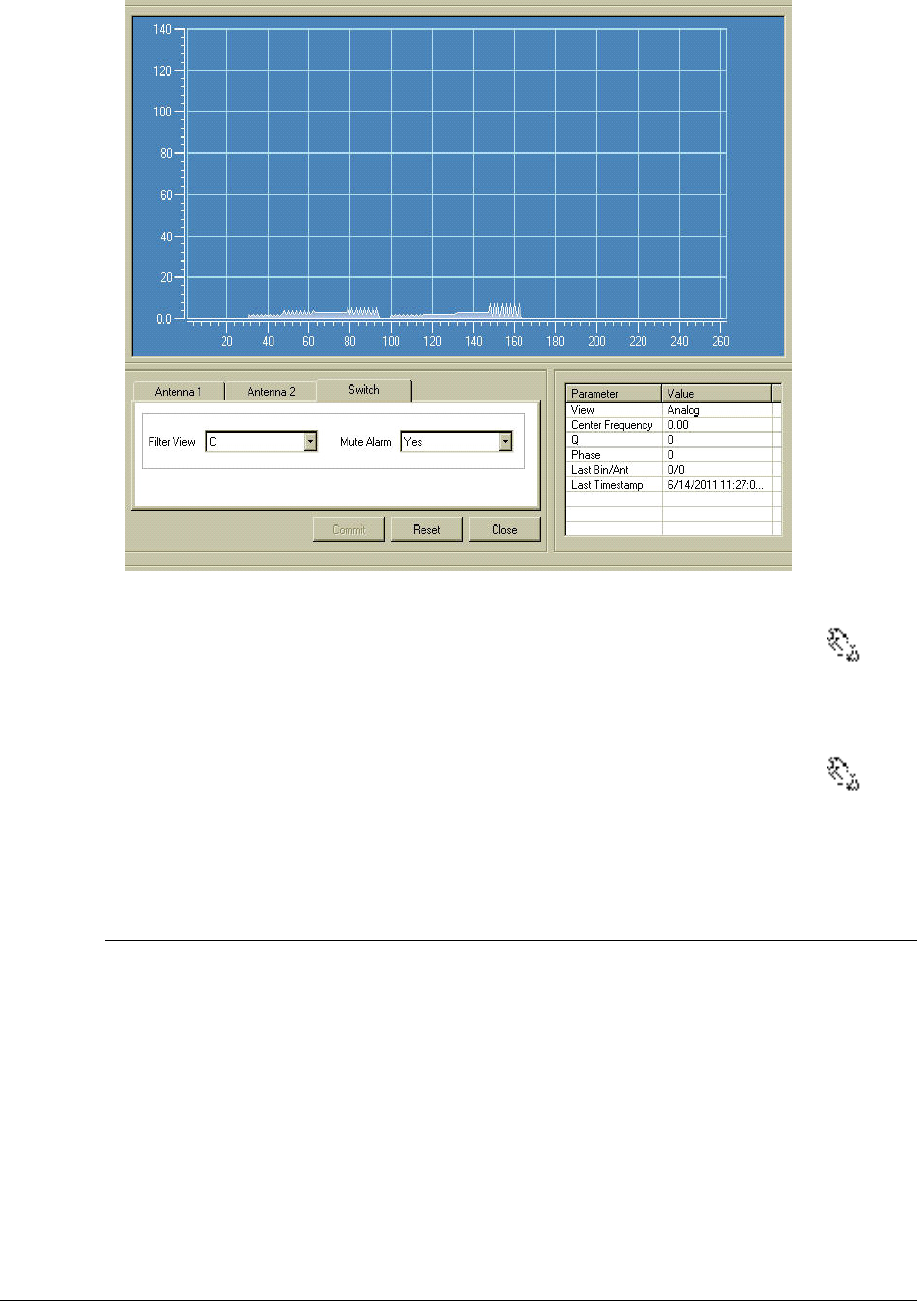
4. Adjust RX gain (software gain) until the noise is just peeking into the Analog View D.
The picture below displays a tuned system.
Figure 44: Noise on Filter View D After RX Gain Tuning
NGL FX Installation Manual Rev. *
75 of 84
CAUTION: In the presence of small resonances, this "spiky noise" will cause the system to false
alarm. Do not leave the system with this level of noise. The receiver gain must be set such that
Filter view 'D is nearly 'flat'.
Identifying and Eliminating a Resonance
A resonance is typically defined as a stationary signal in our band. When in the presence of noise a
resonance may be 'buried' in the noise. By definition, our tags are resonances (resonant circuits).
Our system alarms on resonant circuits on the frequency selected. Once the receiver is set to
acceptable levels of noise, the system must be adjusted to eliminate resonances in the environment.
There are two types of resonances: environmental item resonances and stationary resonances.
• Environmental item resonances are items that can be moved. Examples of environmental item
resonances that must be eliminated are: coils of wire, racks, wiring (Christmas lights) and, of
course, tagged merchandise. Environmental item resonances must be eliminated prior to final
setup.
• Stationary resonances are resonances that cannot be moved or resolved. These include: door
frames, checkout counters, and metal framed walls.
Remedying Resonances
To remedy both stationary resonances and environmental items resonances, the transmitter power
should be adjusted down to acceptable levels in Filter View 'C'. Figure 45 below shows the
reduction in transmitter power from TX@31 to TX@29 in Filter View 'C' will result in acceptable
levels to detect tags
The first figure below shows a low level resonance that is unresolved and could potentially cause
false alarms. The second figure shows the same resonance, but after reducing the TX level.
Figure 45: Unacceptable low level resonance, Filter View 'C' TX Power @31
NGL FX Installation Manual Rev. *
76 of 84
Figure 46: Acceptable low level resonance, Filter View 'C'
Note1:
If the environmental resonances (if any) can be identified and physically removed, then the RX Gain can be set
higher for better detection.
Note2:
The TR4215 board exhibits some natural internal resonance around 8 MHz which does not need to be tuned out.
Because the signal is internal and the fact the Analog View is now multiplied by 2, the typical tuning should look like
the figure 46.
Fixing a Resonance with a Coupler System
1. Check the 2-loop and 3-loop connection. Make sure the 2-loop is connected to J2 and 3-
loop is connected to J3 of the coupler board. An incorrect loop connection will cause a
resonance problem.
2. Then check the antenna loop polarity. The 2-loop and 3-loop should be connected out of
phase. Incorrect polarity will cause resonance problem. If so, normally flipping the
antenna leads of the 3-loop will fix it.
3. Next, check the coupler board jumper settings. Incorrect jumper settings can also cause
resonance problem.

NGL FX Installation Manual Rev. *
77 of 84
Antenna Type Jumper Settings
PX J7, J11
QX J7, J11
Table 10: Coupler Board Jumper Settings
4. Check the cable connection including the RG59 coax and the LED/Sounder cable. Make
sure all cable connection is solid. For the LED/Sounder cable, make sure the ferrite choke
is in place.
5. If there is still resonance, then check the binocular cores, which can cause resonance
problem due to magnetization. Generally the ferrite magnetization issue can be solved by
degaussing. However, in some cases, the ferrites can be irreversibly damaged and have to
be replaced.
6. On the coupler board, ensure that the jumper for J14 of the O-loop is in place for
grounding.
7. The above steps address the resonance problem caused by the system itself. If there is an
environmental resonance, then follow the standard tuning procedure used for regular
Evolve/Liberty systems to alleviate the resonance problem. One common practice is to
change the TX/RX settings. The only difference is that for the Coupler system, the 2-loop
and 3-loop are combined together and cannot be individually tuned in terms of TX/RX.
Jammer Indication
Recently our customers have become concerned about different confiscated jammer devices
blinding our systems by reducing detection and allowing tagged merchandise to become
undetectable. For this reason a jammer indication feature was created to allow the customer to
track these devices. The Jammer Indication feature is enabled when the Jammer Threshold switch
is set to anything other then 0. One of the limitations with the feature is false indications when a
sweeper is in close proximally. This is obvious when enabling this feature. If this is the case, the
feature can not be used. In a clean environment the Jammer Threshold for both PAB and SAB is
set for 11.
Data Retrieval
Event History
The only way to retrieve data from a TR4215 board is to connect to the Badge Board port (RS-232)
using the DMS tool. Using DMS display the Event History and (optionally) save the event history
to a .csv file. The file will be saved in a CSV format in the host computer.
For detailed information about using the DMS tool to access the Event History, please refer to
Field Service Diagnostic Management User Manual.
Snap Shot feature
For detailed information about using the DMS tool to access the Event History and obtain a
snapshot view of the selected alarm (from the last 10 alarm events), please refer to Field Service
Diagnostic Management User Manual.

NGL FX Installation Manual Rev. *
78 of 84
Finishing Installation
Power the system up. Only after the system is fully tuned should the floor cuts be filled with the
flooring material. Concrete mortar, grout, and/or other sealants are applied during this final step,
ensuring the antenna locations are not visible. As mentioned in the site survey***, it is crucial that
the grout be non-metallic and non-magnetic.
Note: If this is a single antenna configuration, then turn off the Transmitter for TX2.
Place Thoro Waterplug Hydraulic cement or Quickrete Fast Set Repair Mortar over all floor cuts.
***Note: Detection performance of the system may be temporarily affected by the water content
in the repair mortar. As the mortar mix cures, detection performance improves.
NGL FX Installation Manual Rev. *
79 of 84
A P P E N D I X
1
POWER SUPPLIES
Power Supply Details
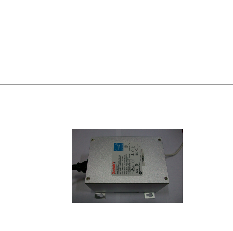
This appendix section covers all available (US and EU) TR4215 FX-compatible power supplies.
Details
Power supplies have an output of +24 VDC.
Requirements
In the US, if the power supply is to be installed in a plenum (HVAC ventilation) area, the Globtek
GS-599ES(R) and the Globtek GS-599MC-KIT(R) must be installed. In the event of such an
installation, the power supply must be hard wired to comply with section 300.22 (C) of the NEC.
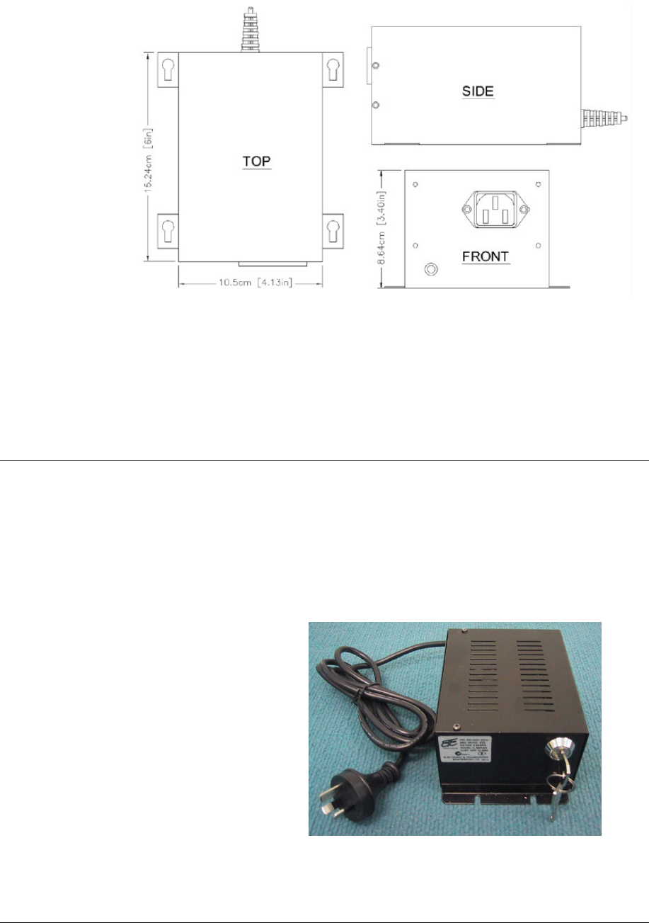
Power Supply Used in United States, Canada and Europe
Model
The FX 2012 product line utilizes the following power supply:
1. Globtek GS-599ES(R) (CKP P/N: 7116509)
Note*: This model is used for non-plenum installations.
2. Globtek GS-599MC-KIT(R) (CKP P/N: 7367100)
Note*: The kit includes the standard power supply (above) and plenum-rated conversion kit.
NGL FX Installation Manual Rev. *
80 of 84
NGL FX Installation Manual Rev. *
81 of 84
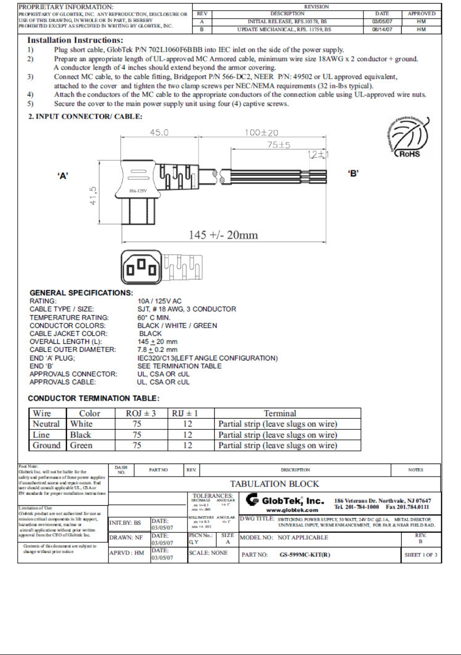
Dimensions
Width: 10.50cm [4.13in]
Length: 15.24cm [6.00in]
Height: 8.64cm [3.40in]
Power Supply Used in Australia
Model
The power supply used in Australia is the ETE 2.5A model, shown below.
Specifications
This unit operates at 240V 50Hz .38A; the output voltage remains 24VDC.
Dimensions:
Width:10.5cm
Length 15.7cm
Height: 7.0cm
NGL FX Installation Manual Rev. *
82 of 84
A P P E N D I X
3
PARTS LIS TS
Shielded FX Parts List
CKP Part # OEM Part # Description
7939172 n/a .38cm x 1.3cm (#7 x ½”) hex head screw
7308823 2348 Power Fastener Zip-it with
.42cm x 2.5cm (#8 x 1”) panhead screw
7366291 9439 Power Fastener .79cm (5/16”) lead anchor
7917157 n/a 5.484 mm x 38.1 mm (#12 x 1 ½”) panhead
screw
7257241 Belden 8723
Consolidated 5594
Approved Sync Cable
7327686 Dryconn 62110 or
62125
Waterproof wire nut
Contractor Supplied
T5002/1241 Thoro Waterplug Hydraulic Cement T5002,
10 lb can / Quickrete Fast Set Repair Mortar
1241
Contractor Supplied
n/a Sand used to level bottom of trough under
panels
Contractor Supplied
n/a 1.9cm (¾”) PVC conduit, contractor supplied.
Used to house 15.1m [50ft] transmission line
in new installations before slab is poured.
Unshielded FX Parts List
CKP Part # OEM Part # Description
7939172 n/a 0.38cm x 1.3cm (#7 x ½”) hex head screw
7308823 2348 Power Fastener Zip-it with
0.42cm x 2.5cm (#8 x 1”) panhead screw
7366291 9439 Power Fastener .79cm (5/16”) lead anchor
7917157 n/a 5.484 mm x 38.1 mm (#12 x 1 ½”) panhead screw
7257241 n/a Approved Sync Cable: Belden # 8723 & Consolidated # 5594
*** n/a 1.9cm (¾ inch) PVC conduit, contractor supplied
7327686 Dryconn 62110 Waterproof wire nut
NGL FX Installation Manual Rev. *
83 of 84
or 62125
Contractor
Supplied
n/a 1.9cm (¾”) PVC conduit, contractor supplied (used to house
15.1m (50’) transmission line in new installations before slab
is poured.)
Contractor
Supplied
T5002/1241 Thoro Waterplug Hydraulic Cement T5002, 10 lb can or
Quickrete Fast Set Repair Mortar 1241
A P P E N D I X
4
IN TERA CTIONS
FX System – Proximity to Deactivation Units
The table below lists minimum distances where Counterpoint IX or D11 Deactivators can be
located away from a FX system antenna.
Deactivators do not affect the FX system performance.
However, in 4 and 6 Mode, if any FX system is located inside a 1.8m [6ft] radius from the
deactivator, false alarms may occur because the deactivator “sees” the system.
It is not possible to slave a deactivator to a system with Strata-based electronics.
Note*: The deactivator will intermittently alarm as it sees the FX pulsing, these alarms will occur
on average every 30 seconds.
Distance to FX System
MODELS
(all with pad) Up to 1.8m (6.0') > 1.8m (6.0')
CP IX/D11
4 Mode
Deactivator Phantoms
(see note) No Interactions
CP IX/D11
5 Mode No Interactions No Interactions
NGL FX Installation Manual Rev. *
84 of 84
FX System – Proximity to Other Systems
Please refer to the table below for details on how close systems can be to one another.
Liberty FX to: Minimum Separation w/o Slaving Slave Options
Any pedestal or
floor system
12m [40 feet]
Slave
Pillar / Frame
4.6m [15 feet] None
QS4000XT
4.6m [15 feet] None
QS2000
4.6m [15 feet] None
Signature
4.6m [15 feet] None
Quicksilver
4.6m [15 feet] None
QS6500
7.6m [25 feet] None
QS45/55
7.6m [25 feet] None