Checkpoint Systems FX2012 Electronic Article Surveillance Detection System User Manual FX 2012 Installation Guide Part 2
Checkpoint Systems Inc Electronic Article Surveillance Detection System FX 2012 Installation Guide Part 2
Contents
- 1. FX 2012 Installation Guide Part 1
- 2. FX 2012 Installation Guide Part 2
- 3. FX 2012 Installation Guide Part 3
FX 2012 Installation Guide Part 2
NGL FX Installation Manual Rev. *
35 of 84
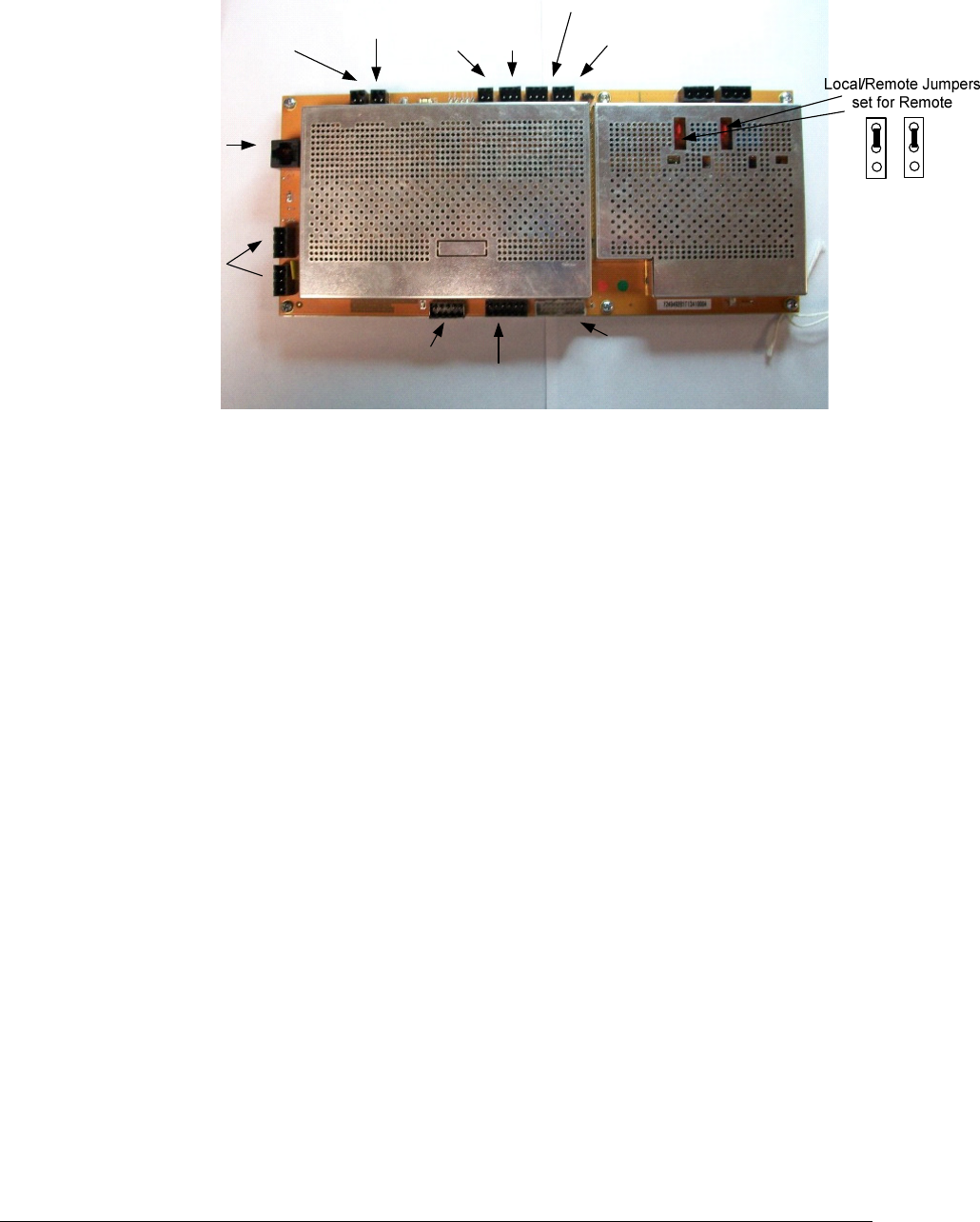
TX1TX2
Sync In
Sync Out
PAB
Lights
Metal
Point
SAB
Lights
PAB
Sounder
SAB
Sounder
Badge
Board
Input
Power
Alarm
Relay
Optional 3
rd
TX Interface
Figure 6X*** TR4215 Reader Board
Figure X*** shows the specific connectors for the peripherals. ** J numbers for the connectors.
NGL FX Installation Manual Rev. *
36 of 84
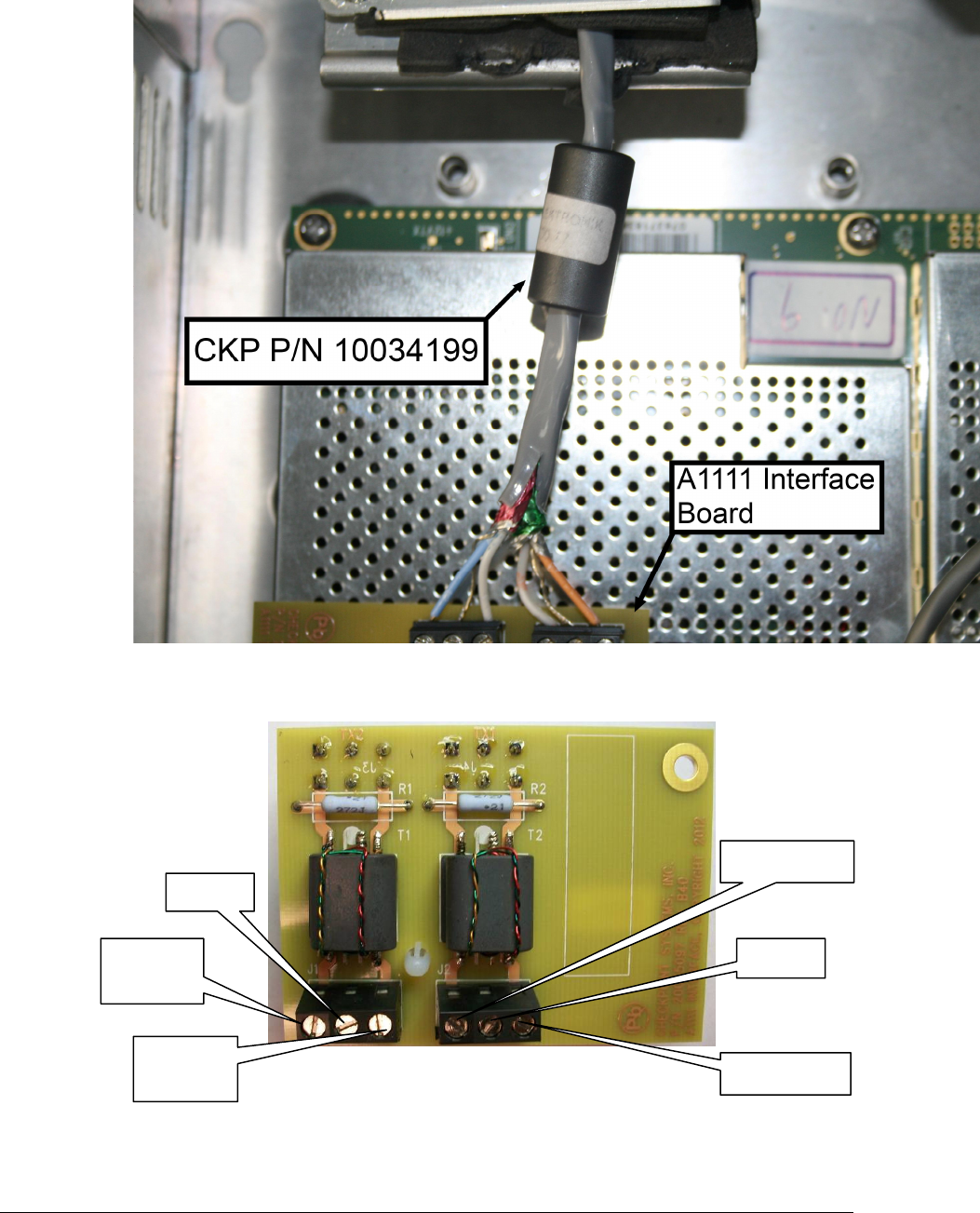
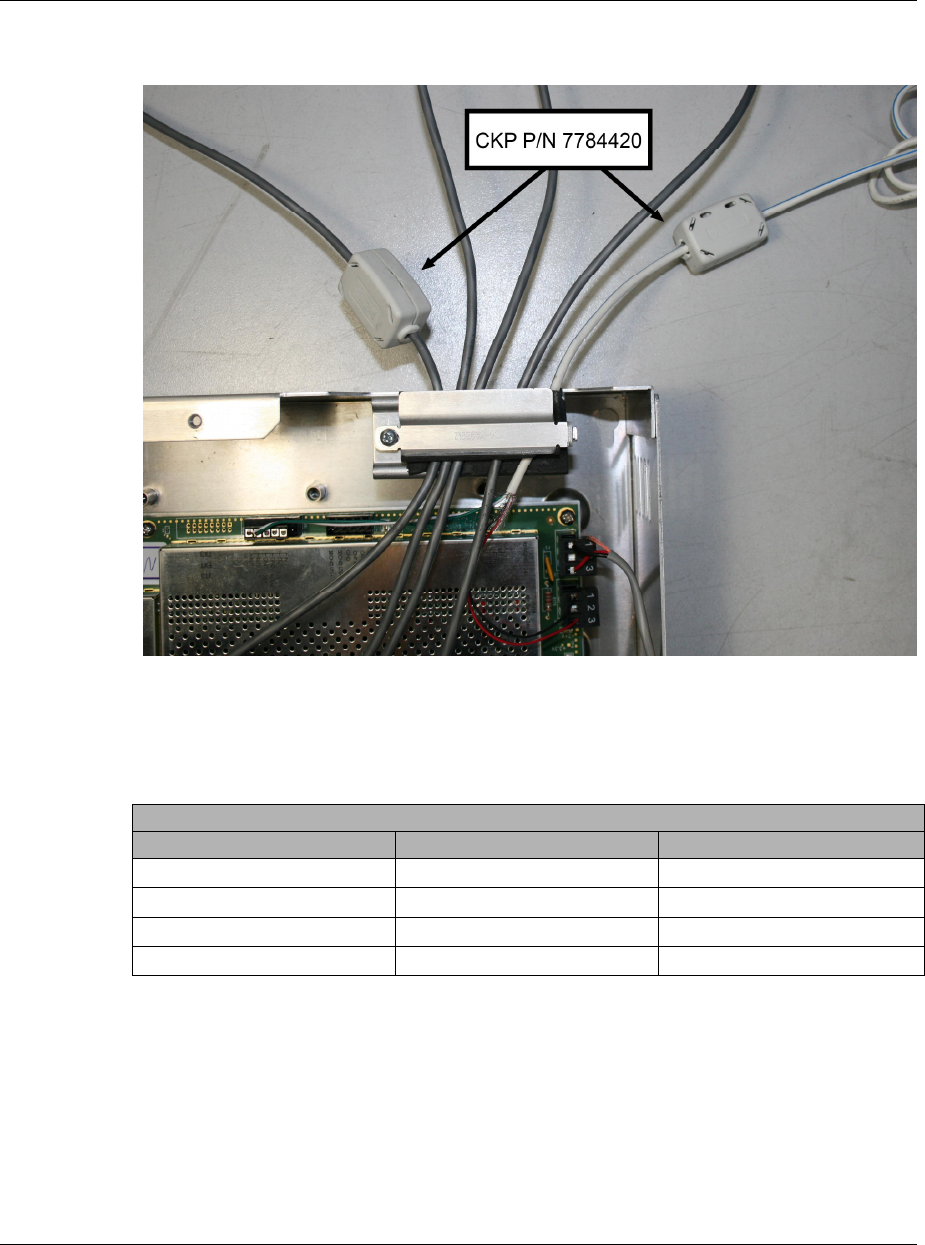
Transmission Line / A1111 Wiring
The A1111interface board connects to each FX antenna via the 15m (50 ft) transmission line.
Apply the ferrite cores as show and tighten the clamp.
Figure X** displays the interface board and connections.
Before connecting to the A1111 board, slide the ferrite core (P?N) over the transmission cable.
NGL FX Installation Manual Rev. *
37 of 84
Connect the leads according to the diagram below and tighten clamps that hold the wires to the
chassis. ***Update Graphic.
Figure 16: A1111 Wire terminal Connections
At Connector Port J1 (TX2):
DRAIN
ORANGE/
WHITE
WHITE/
ORANGE
DRAIN
WHITE/BLUE
BLUE/WHITE
NGL FX Installation Manual Rev. *
38 of 84
• Connect one drain wire from the 15.2m (50-ft) transmission line to the center terminal
• Connect the ORANGE/WHITE lead to the terminal left of this drain wire
• Connect the WHITE/ORANGE lead to the terminal right of this drain wire
At Connector Port J2 (TX1):
• Connect the second drain wire from the 15.2m (50-ft) transmission line to the center terminal
• Connect the BLUE/WHITE lead to the terminal left of this drain wire
• Connect the WHITE/BLUE lead to the terminal right of this drain wire
.
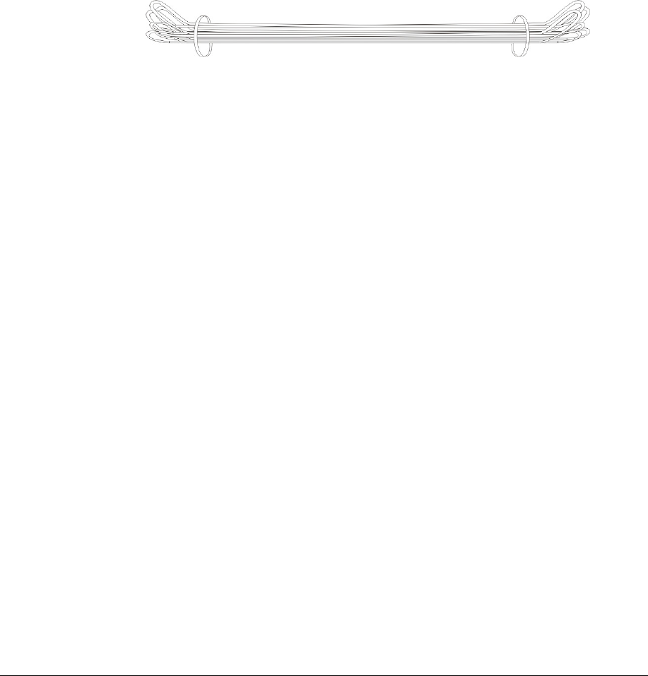
When the length is less than 15.2m ± .3 m (50’ ± 1”), you should wrap up the cable so that it looks
like a dog bone, with small loops at either end, loosely secured by tie wraps. Place the wrapped
cable next to the electronics enclosure. Do not coil the cable as it will appear as a large tag to the
antennas.
Figure 10: Wrapped Cable
NGL FX Installation Manual Rev. *
39 of 84
Remote voice alarm or alarm post
Connect the peripheral Lights and Sounder wiring as indicated below. Remote voice alarm or
alarm post. White wire connects to the voice alarm.
Figure 32: Ferrite clip installed on ALG SYNC IN (TR4215 Port J22) & ALG SYNC OUT
(TR4215 Port J20) cable
SAB Light/Sounder Cable Wiring Table ***reflect voice alarm or alarm post wiring
Wire Color Primary Antenna (PAB) Secondary Antenna (SAB)
WHITE J41-5 LT+
GREEN J41-4 LT-
RED J54-1 SD+
BLACK J54-2 SD-
Table 1 SAB Light/Sounder Cable Wiring Table
NGL FX Installation Manual Rev. *
40 of 84
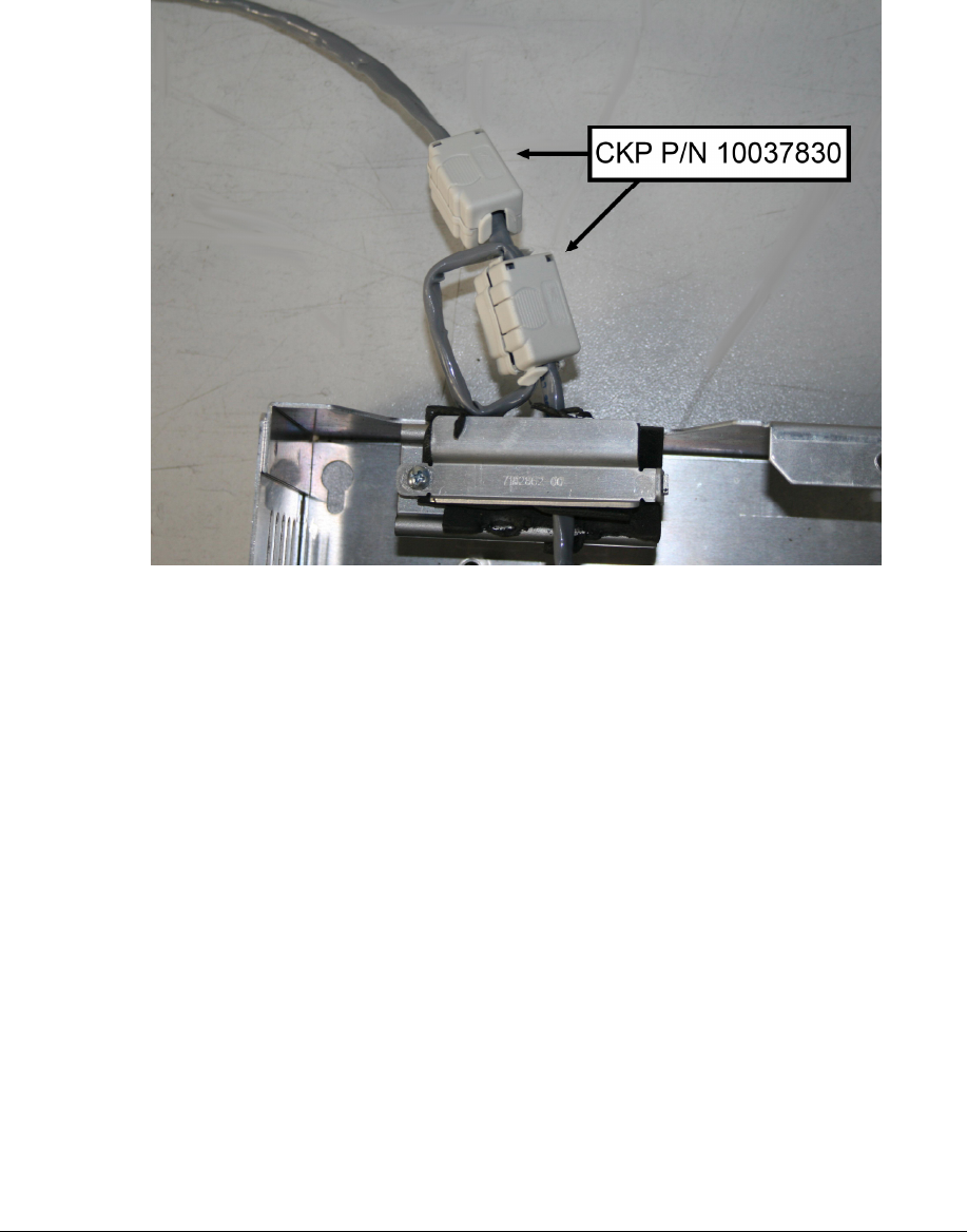
Wiring Between FX Systems for Sync
Where multiple floor systems are installed, it may be necessary to install sync wire and network
communication cable between the aisles.
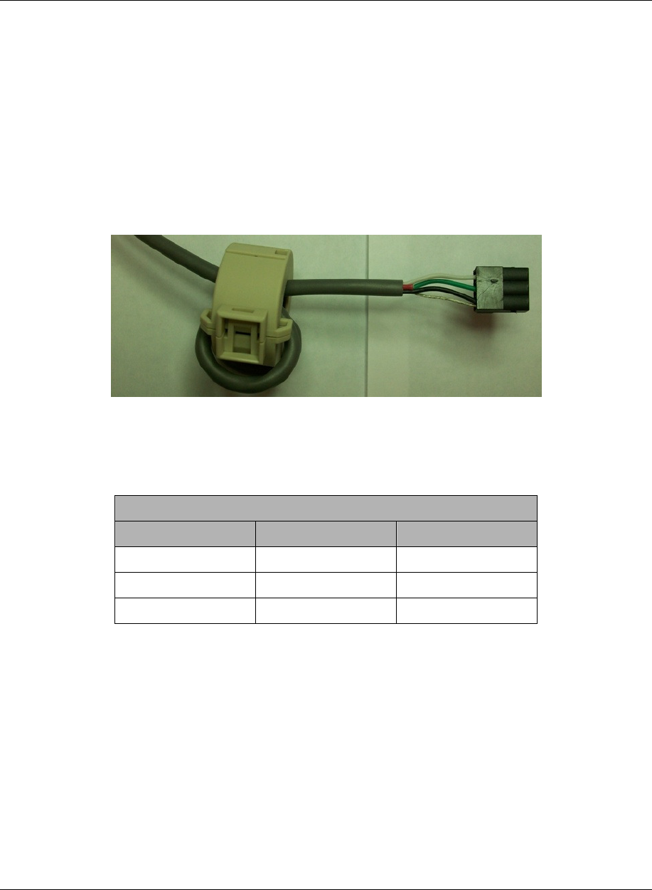
Sync Cable
The sync cable (RF Sync) should be installed between FX systems if the distance between aisles is
under 40 feet. If two aisles are more than 40 feet apart, no sync cable is needed. Use 22 AWG
4-conductor (STP) (5594) cable for sync cable. Follow the Sync Cable Wiring Table below to
wire it to appropriate terminals. Sync cables are wired in daisy chain style. There are two sync
cables in a PAB antenna, the input cable and the output cable. The first antenna only uses Sync
Output cable, the last has the Input sync cable. The Output cable connects from terminal (J22) to
Sync Input terminal (J20) on the synced system.
Please refer the table below for Sync wire terminal connector pin assignment.
Figure 10 Sync cable with ferrite core
Note: A ferrite core with three (3) turns is attached at each end.
Sync Input (5594 4-conductor 22AWG wire)
Wire Color Description J20/J22
White SYNC - 1
Green SYNC + 2
Black & Drain GND 3
Table 2 Sync Cable Wiring Table
NGL FX Installation Manual Rev. *
41 of 84
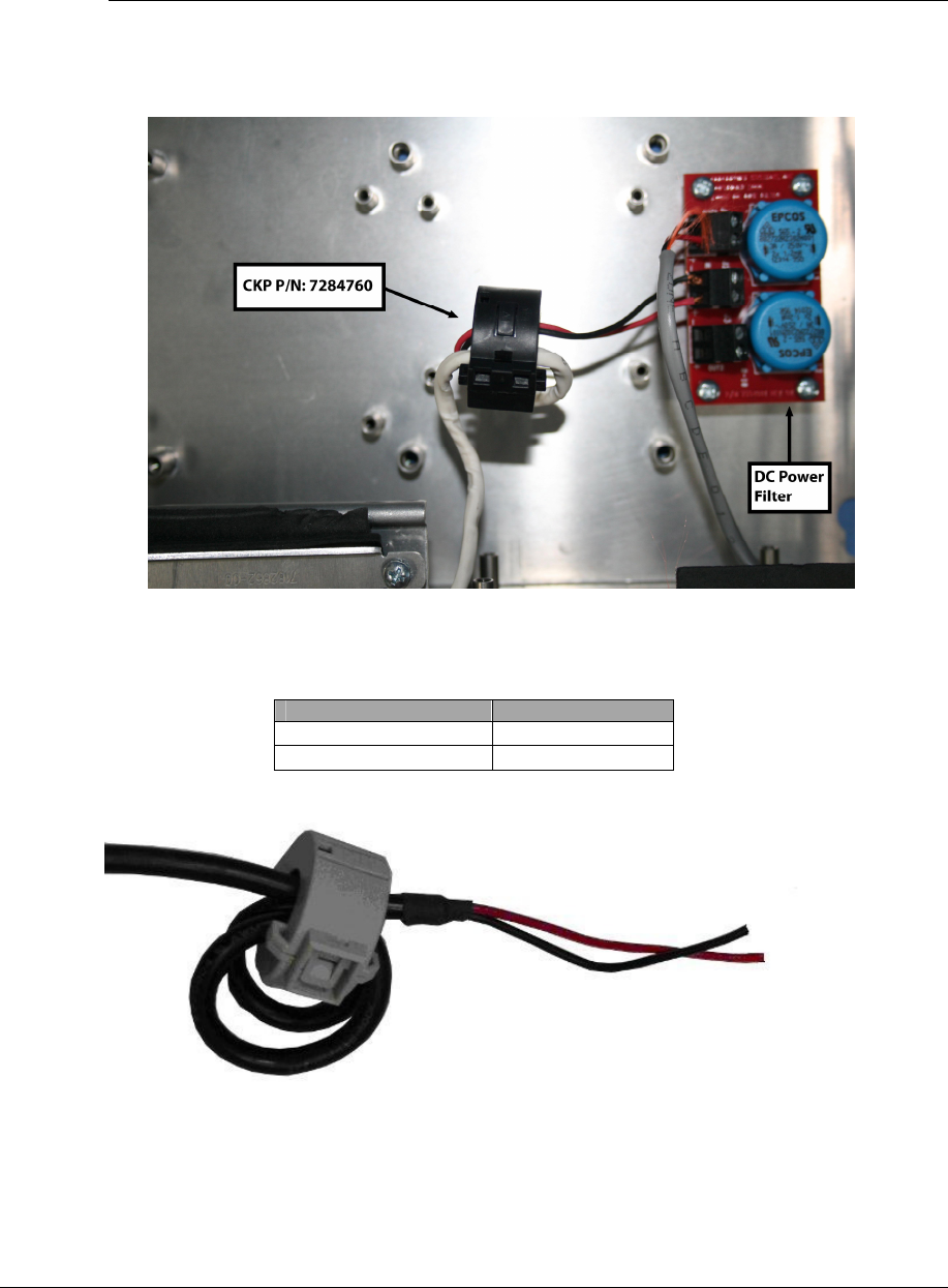
Wiring 24VDC power supply
A Checkpoint-certified 24VDC power supply can power up to two (2) FX systems. The cable is
plenum rated (MC Armored cable) with AWG18 two (2) conductor cable + ground.
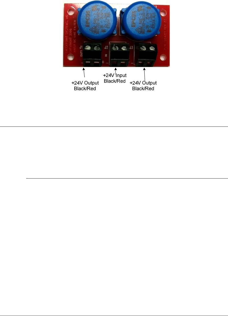
Wire the plenum cable to the DC filter board input according to the Pinout below. Connect the
wires from this PAB’s filter board to J18 connector on the reader. The other output from the filter
board could be wired to other PAB filter board input. *** fix wiring instruction.
Wire Color Description
Black GND
Red +24 V
Table 3 Power Cable Wiring Table
Figure 11 24 VDC Power Supply Cable
NGL FX Installation Manual Rev. *
42 of 84
Figure 12 24 VDC power filter
Synchronizing, Slaving and System Proximity
Systems operating together as a unit, as opposed to individual floor systems***, have to be
synchronized or “synced” together using an approved sync cable for the system (i.e., Belden #
8723, Consolidated # 5594, etc.). At minimum there should be a 2 wire and shield. This minimum
wire will not give an alarm group function. For alarm grouping, a 2 pair with shield cable must be
used.
Wiring peripherals
Follow the appropriate installation manual for wiring peripheral devices.

NGL FX Installation Manual Rev. *
43 of 84
C H A P T E R
5
NETWORKING AND PERIPHERALS
Overview
This chapter describes the PX/QX with Coupler antennas peripheral device wiring.
Note: peripheral device wires go to primary antenna only.
Peripherals
Both PX and QX with Coupler systems support following peripheral devices:
Voice Alarm
Metal Detection
Please refer the peripheral device’s installation manuals for proper installation and wiring
NGL FX Installation Manual Rev. *
44 of 84
C H A P T E R
6
NGL SYSTEM CONFIGURATION VIA DMS
Overview
This chapter reviews the DMS configuration steps for the FX system using DMS.
Antenna tuning including coupler jumper setting is covered in Chapter 7: NGL Tuning. Please
follow this tuning guide to optimize the system performance after completing the system
configuration.
Note: Please use DMS version 1.8.31 and later. TR4215 firmware version must be 4.00 and
later.
System Setup Using DMS
The following sections describe the basic NGL setup under two different aisle configurations:
Single-Aisle and Multi-Aisle. In either case, the basic setup is similar but an extra step is needed
for Multi-Aisle configuration.
The instructions below emphasize which parameters should be setup for the TR4215 board. It
does not go into detail about using the DMS tool or how to navigate to the specified setup
Windows. A basic knowledge of the DMS tool is assumed.
Note: Please refer Field Service Diagnostic Management User Manual for general help with
using the DMS tool.
Basic setup
The basic setup process consists of following steps:
1. Make a new DMS connection – for new installation
2. Configure PAB/SAB (coupler) operation mode
Make a New DMS Connection
3. Connect the service PC laptop to the serial port on the TR4215 board.
4. Launch the DMS program (version 1.8.31 or later) and enter your login information.
5. Make a new Connection for connecting to the TR4215 board. Be sure to select "(Direct)
Serial" for the Type and "Evolve" as the Device.
Unlike previous Liberty Systems, NGL does not use the "TR4024/26" Device Connection.
Figure X*** New Connection Setup shows the "Add Connection" window with the
appropriate NGL settings.