Checkpoint Systems FX2012 Electronic Article Surveillance Detection System User Manual FX 2012 Installation Guide Part 2
Checkpoint Systems Inc Electronic Article Surveillance Detection System FX 2012 Installation Guide Part 2
Contents
- 1. FX 2012 Installation Guide Part 1
- 2. FX 2012 Installation Guide Part 2
- 3. FX 2012 Installation Guide Part 3
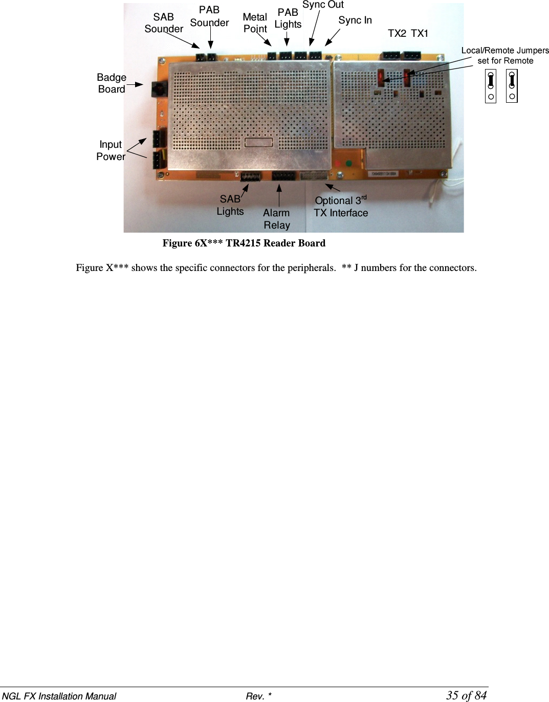
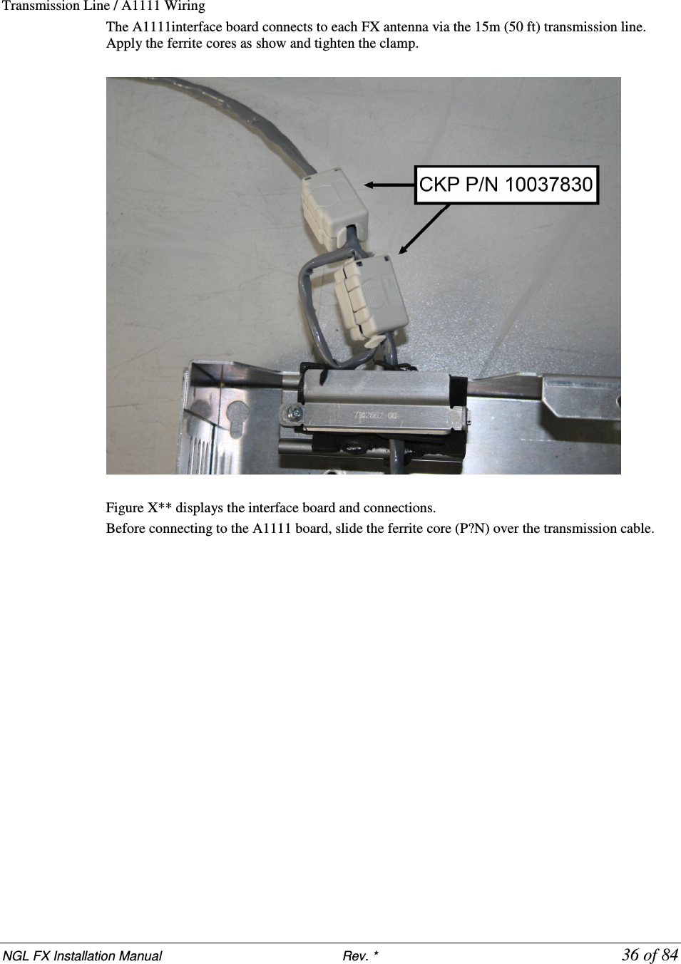
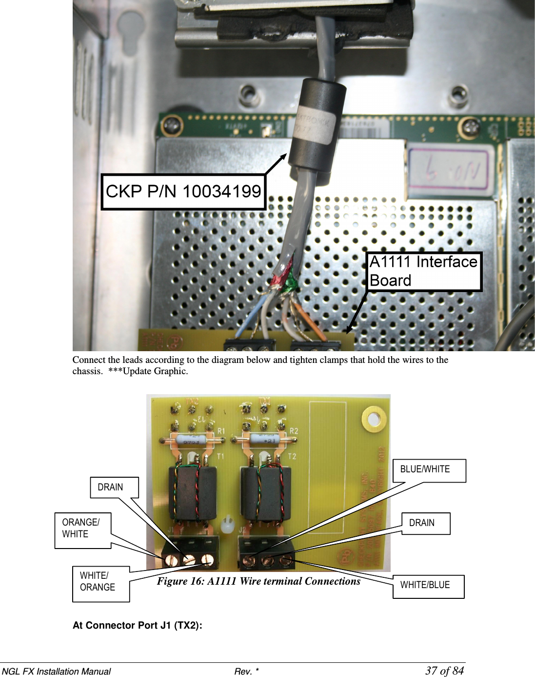
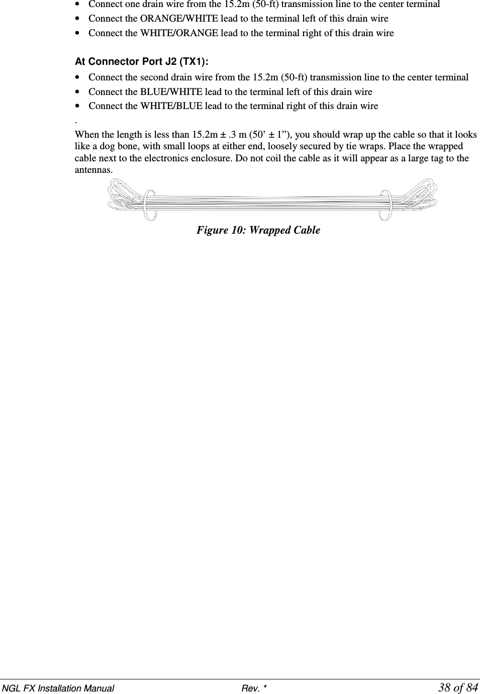
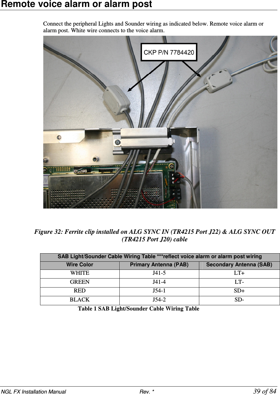
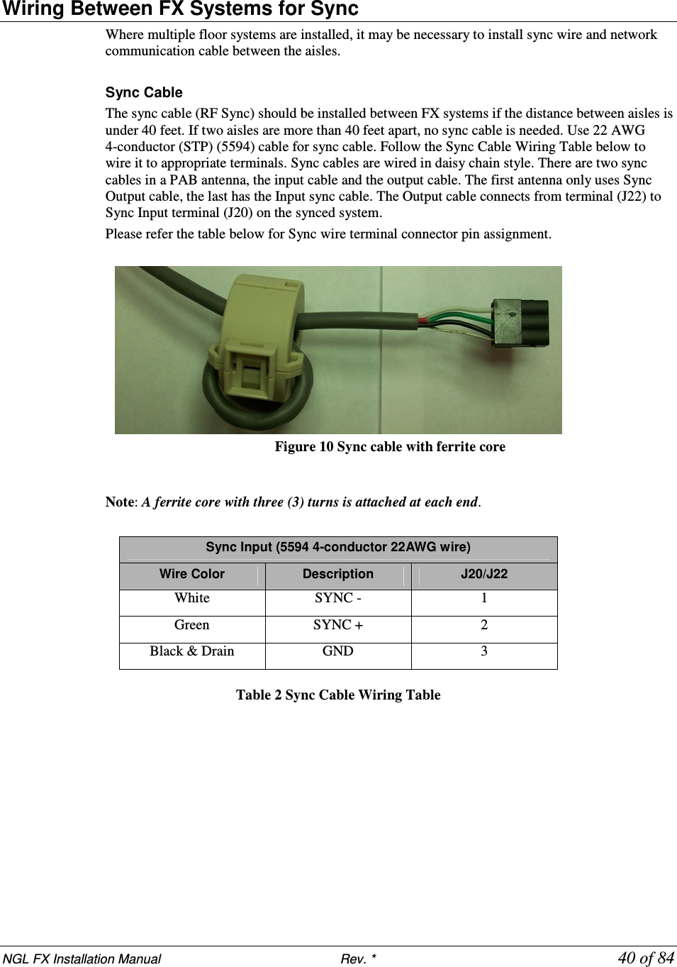
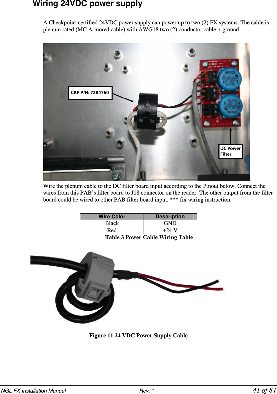
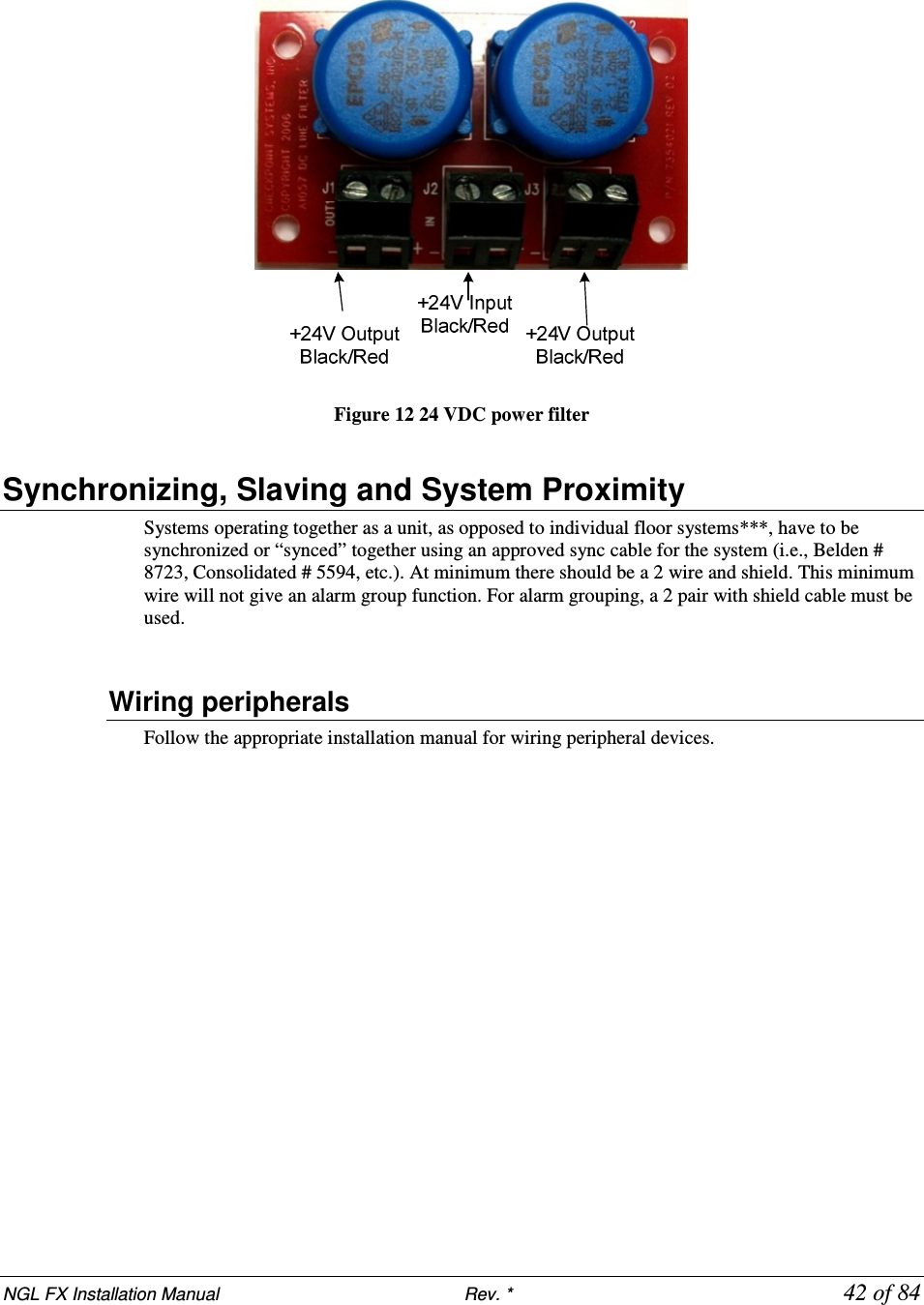
FX 2012 Installation Guide Part 2