Checkpoint Systems FX2012 Electronic Article Surveillance Detection System User Manual FX 2012 Installation Guide Part 1
Checkpoint Systems Inc Electronic Article Surveillance Detection System FX 2012 Installation Guide Part 1
Contents
- 1. FX 2012 Installation Guide Part 1
- 2. FX 2012 Installation Guide Part 2
- 3. FX 2012 Installation Guide Part 3
FX 2012 Installation Guide Part 1

NGL FX 2012
Installation Manual
Document Version 00
P/N
7360602

NGL FX Installation Manual Rev. *
2 of 84
NGL FX 2012 Installation Manual
Copyright © 2012 by Checkpoint Systems Inc.
Released August 31, 2012.
Published by:
Checkpoint Systems Inc.
101 Wolf Drive
Thorofare, NJ 08086
For use with the Checkpoint NGL FX 2012 System both Shielded and Unshielded in-floor models.
Trademarks
Checkpoint is a registered trademark of Checkpoint Systems, Inc.
Checkpoint, Liberty, Evolve, and VisiPlus are registered trademarks of Checkpoint Systems, Inc. All
rights reserved. Information in this document is subject to change without notice.
Other products © or ® their respective manufacturers or copyright holders.
Companies, names and data used in examples herein are fictitious unless otherwise noted. No part of
the contents of this book may be reproduced or transmitted in any form or by any means without the
written permission of the publisher.
Copyright and Warranty Information
All rights reserved. The information in this document is subject to change without notice.
Because of the changing nature of this product information presented in the FX Installation Manual,
Checkpoint Systems, Inc. is not liable for any omissions, misstatements, or other errors of
information.
The information presented in this document may not be copied, used or disclosed to others for the
purpose of procurement or manufacturing without the written permission of Checkpoint Systems,
Inc. This guide and the products discussed in this guide are the exclusive property of Checkpoint
Systems Inc. Copyright laws of the United States protect all information and products.
Copyright© 2012 Checkpoint Systems, Inc. All rights reserved.
Document Revision Information
Part Number: 7360602
FX 2012 Installation Manual, version 01
Rev Description Date Author
* Preliminary Release 8/31/2012 Ron Decker, Joseph Galanti

NGL FX Installation Manual Rev. *
3 of 84
Statements
• The device(s) may only be used for the intended purpose designed by for the manufacturer.
• Unauthorized changes and the use of spare parts and additional devices which have not been sold or
recommended by the manufacturer may cause fire, electric shocks or injuries. Such unauthorized measures
shall exclude any liability by the manufacturer.
• The liability-prescriptions of the manufacturer in the issue valid at the time of purchase are valid for the
device. The manufacturer shall not be held legally responsible for inaccuracies, errors, or omissions in the
manual or automatically set parameters for a device or for an incorrect application of a device.
• Repairs may only be executed by the manufacturer.
• Installation, operation, and maintenance procedures should only be carried out by qualified personnel.
• Use of the device and its installation must be in accordance with national legal requirements and local
electrical codes.
• When working on devices the valid safety regulations must be observed.
• Before touching the device, the power supply must always be interrupted. Make sure that the device is
without voltage by measuring. The fading of an operation control (LED) is not an indicator for an interrupted
power supply or the device being out of voltage!
• The installer or licensed electrician must follow all NEC and local codes.
• All wires routed in the floor per article 725 must be Class 2 and be UL Listed. UL Recognized AWM may be
employed, provided it is enclosed in Conduit of ENT.
• Inter-pedestal wiring should not be directly installed in wet concrete.
Guide Conventions
Document conventions are described below:
• This is a Warning icon. When it appears, it indicates a potentially hazardous situation, which if not
avoided, could result in death or serious injury.
• Caution: This is a Caution icon. When it appears, it indicates a potentially hazardous situation which
if not avoided, could result in property damage or malfunction of equipment.
• Note: This is a Tip icon. When it appears, the corresponding text indicates a helpful note or tip when
using the feature.
For all measurements:
• To meet both CE and FCC requirements, all measurements will be listed in the following format: Metric
[Imperial], for example: 46cm [18in] or 0.9m [3ft].
• Where non-S.I. units are applicable, such as 6’ x 4’ or 3/16”, the format is Unit (metric).
Where on-screen computer instructions are given:
Button Name - This describes a button or an on-screen command or drop-down selection.
For example, the <DONE> button is represented in this document as Done.
Key Name - This describes a keystroke on a keyboard. For example, Ctrl represents the control key.

NGL FX Installation Manual Rev. *
4 of 84
Important Information to our Users in North America
FCC Regulatory Compliance Statement
Checkpoint Systems, Inc., offers Electronic Article Surveillance (EAS) or Radio Frequency
Identification Products that have been FCC certified or verified to 47 CFR Part 15 Subparts B/C.
Appropriately, one of the following labels will apply to the approval:
NOTE: This equipment has been tested and found to comply with the limits for a class A digital
device, pursuant to Part 15 of the FCC Rules. These limits are designed to provide reasonable
protection against harmful interference when the equipment is operated in a commercial
environment. This equipment generates, uses, and can radiate interference to radio
communications. Operation of this equipment in a residential area is likely to cause harmful
interference in which case the user will be required to correct the interference at his own expense.
- OR -
This device complies with Part 15 of the FCC Rules. Operation is subject to the following
two conditions: (1) including this device may not cause harmful interference, and (2) this
device must accept any interference received, including interference that may cause
undesired operation, which may include intermittent decreases in detection and/or
intermittent increases in alarm activity.
Industry Canada Regulatory Compliance Statement
Under Industry Canada regulations, this radio transmitter may only operate using an antenna of a
type and maximum (or lesser) gain approved for the transmitter by Industry Canada. To reduce
potential radio interference to other users, the antenna type and its gain should be so chosen that
the equivalent isotropically radiated power (e.i.r.p.) is not more than that necessary for successful
communication.
This radio transmitter (IC: 3356B-FX2012) has been approved by Industry Canada to operate with
the antenna types listed below with the maximum permissible gain and required antenna
impedance for each antenna type indicated. Antenna types not included in this list, having a gain
greater than the maximum gain indicated for that type, are strictly prohibited for use with this
device.
Operation is subject to the following two conditions:
(1) this device may not cause interference, and
(2) this device must accept any interference, including interference that may cause undesired
operation of the device.
To reduce potential radio interference to other users, the antenna type and its gain should be so
chosen that the equivalent isotropically radiated power (e.i.r.p.) is not more than that permitted for
successful communication.

NGL FX Installation Manual Rev. *
5 of 84
Industrie Canada
Conformément à la réglementation d'Industrie Canada, le présent émetteur radio peut fonctionner
avec une antenne d'un type et d'un gain maximal (ou inférieur) approuvé pour l'émetteur par
Industrie Canada. Dans le but de réduire les risques de brouillage radioélectrique à l'intention des
autres utilisateurs, il faut choisir le type d'antenne et son gain de sorte que la puissance isotrope
rayonnée équivalente (p.i.r.e.) ne dépasse pas l'intensité nécessaire à l'établissement d'une
communication satisfaisante.
Le présent émetteur radio (IC: 3356B-FX2012) a été approuvé par Industrie Canada pour
fonctionner avec les types d'antenne énumérés ci-dessous et ayant un gain admissible maximal et
l'impédance requise pour chaque type d'antenne. Les types d'antenne non inclus dans cette liste, ou
dont le gain est supérieur au gain maximal indiqué, sont strictement interdits pour l'exploitation de
l'émetteur.
Le fonctionnement de l’ appareil est soumis aux deux conditions suivantes:
(1) Cet appareil ne doit pas perturber les communications radio, et
(2) cet appareil doit supporter toute perturbation, y compris les perturbations qui pourraient
provoquer son dysfonctionnement.
Pour réduire le risque d'interférence aux autres utilisateurs, le type d'antenne et son gain
doivent être choisis de façon que la puissance isotrope rayonnée équivalente (PIRE) ne
dépasse pas celle nécessaire pour une communication réussie.
Equipment Safety Compliance Statement
Checkpoint Systems’ EAS or Radio Frequency Identification products have been designed to be
safe during normal use and, where applicable, certain components of the system or accessory sub-
assemblies have been certified, listed or recognized in accordance with one or more of the
following Safety standards: UL 1012, UL 1037, UL 1310, UL 60950-1, CSA C22.2 No. 205, CSA
C22.2 No. 220, CSA C22.2 No. 223, CSA C22.2 No. 60950-1. Additional approvals may be
pending.
WARNING: Changes or modifications to Checkpoint’s EAS or Radio Frequency Identification
(RFID) equipment not expressly approved by the party responsible for assuring compliance could
void the user’s authority to operate the equipment in a safe or otherwise regulatory compliant
manner.

NGL FX Installation Manual Rev. *
6 of 84
Important Information to our Users in Europe
CE Regulatory Compliance Statement
Where applicable, Checkpoint Systems, Inc., offers certain Electronic Article Surveillance (EAS)
products that have CE Declarations of Conformity according to R&TTE Directive 99/5/EC, EMC
Directive 2004/108/EC, and Low Voltage Directive 2006/95/EC.
System Electromagnetic Compatibility (EMC), has been tested and notified through Spectrum
Management Authorities if necessary, using accredited laboratories, whereby, conformity is
declared by voluntarily accepted European Telecommunications Standards Institute (ETSI)
standards EN 301489-1 and EN 300330-2.
NOTE: Certain Electronic Article Surveillance (EAS) equipment have been tested and found to
conform with the CE emission and immunity requirement in Europe. This equipment generates,
uses, and can radiate radio frequency energy and, if not installed and used in accordance with the
instruction manual, may cause harmful interference to radio communications. Under unusual
circumstances, interference from external sources may degrade the system performance, which
may include intermittent decreases in detection and/or intermittent increases in alarm activity.
However, there is no guarantee that interference will not occur in a particular installation. If this
equipment experiences frequent interference from external sources or does cause harmful
interference to radio communications reception, which can be determined by turning the
equipment off and on, please contact a Checkpoint Systems representative for further assistance.
Equipment Safety Compliance Statement
Checkpoint Systems Electronic Article Surveillance products have been designed to be safe during
normal use and, where applicable, certain components of the system or accessory sub-assemblies
have been declared safe according to the European Low Voltage Directive (LVD) by being
certified, listed, or recognized in accordance with one or more of the following European safety
standards; EN 60950-1, EN 50364, EN 60742.
WARNING: Changes or modifications to Electronic Article Surveillance equipment not expressly
approved by the party responsible for assuring compliance could void the user’s authority to
operate the equipment in a safe or otherwise regulatory compliant manner additional approvals
may be pending.

NGL FX Installation Manual Rev. *
7 of 84
Table of Contents
STATEMENTS ............................................................................................................................................................3
GUIDE CONVENTIONS ...........................................................................................................................................3
TABLE OF CONTENTS ............................................................................................................................................7
CHAPTER 1 INTRODUCTION..............................................................................................................................10
BACKGROUND ........................................................................................................................................................10
C
HAPTER
O
VERVIEW
...............................................................................................................................................11
SHIELDED VS. UNSHIELDED FX SYSTEM HARDWARE..............................................................................11
S
HIELDED
FX
S
YSTEM
D
IAGRAMS
..........................................................................................................................12
U
NSHIELDED
FX
S
YSTEM
D
IAGRAMS
......................................................................................................................13
CHAPTER 2SITE PLANNING ...............................................................................................................................15
O
VERVIEW AND
G
OALS
...........................................................................................................................................15
ANTENNA DISTANCE FROM INTERFERING ELEMENTS...........................................................................15
D
ETERMINING THE
E
LECTRONICS
L
OCATION
..........................................................................................................16
D
ETERMINING THE
A
PPROPRIATE
S
YSTEM
T
YPE
.....................................................................................................16
E
NVIRONMENTAL
C
ONSIDERATIONS
***.................................................................................................................17
P
ERFORM A
D
RY
R
UN
..............................................................................................................................................17
S
ITE
S
URVEY
C
ONCLUSION
.....................................................................................................................................18
CHAPTER 3 PHYSICAL INSTALLATION..........................................................................................................19
C
HAPTER
O
UTLINE
..................................................................................................................................................19
REQUIREMENTS ....................................................................................................................................................19
T
OOLS
.....................................................................................................................................................................19
P
ARTS
......................................................................................................................................................................20
INSTALLATION OUTLINE ...................................................................................................................................20
FX ANTENNA INSTALLATION............................................................................................................................20
D
URING
C
ONSTRUCTION
.........................................................................................................................................20
A
FTER
C
ONSTRUCTION
............................................................................................................................................20
SHIELDED FX ANTENNA FLOOR CUTS ...........................................................................................................21
U
NSHIELDED
FX
A
NTENNA
F
LOOR
C
UTS
................................................................................................................23
P
OTTED
M
ATCHING
B
OARD
C
UTS
–
U
NSHIELDED
FX
O
NLY
...................................................................................25
M
OUNTING THE
E
LECTRONICS
E
NCLOSURE
............................................................................................................26
M
OUNTING THE
P
OWER
S
UPPLY
..............................................................................................................................28
GS-599ES(R)
I
NSTALLATION
..................................................................................................................................28
GS-599MC-KIT(R)
I
NSTALLATION
........................................................................................................................28
CHAPTER 4 WIRING..............................................................................................................................................29
OVERVIEW ..............................................................................................................................................................29
ANTENNA WIRING ................................................................................................................................................30
S
HIELDED
FX
A
NTENNA
..........................................................................................................................................30
W
IRING THE
P
OTTED
M
ATCHING
B
OARD
................................................................................................................30
U
NSHIELDED
FX
A
NTENNA
.....................................................................................................................................32
W
IRING THE
P
OTTED
M
ATCHING
B
OARD
................................................................................................................32
TR4215 COMPONENTS AND ENCLOSURE.......................................................................................................34
O
VERVIEW
...............................................................................................................................................................34
T
RANSMISSION
L
INE
/
A1111
W
IRING
.....................................................................................................................36
REMOTE VOICE ALARM OR ALARM POST ...................................................................................................39
W
IRING
B
ETWEEN
FX
S
YSTEMS FOR
S
YNC
.............................................................................................................40

NGL FX Installation Manual Rev. *
8 of 84
W
IRING
24VDC
POWER SUPPLY
..............................................................................................................................41
SYNCHRONIZING, SLAVING AND SYSTEM PROXIMITY ...........................................................................42
W
IRING PERIPHERALS
..............................................................................................................................................42
CHAPTER 5NETWORKING AND PERIPHERALS ...........................................................................................43
OVERVIEW ..............................................................................................................................................................43
PERIPHERALS.........................................................................................................................................................43
CHAPTER 6 NGL SYSTEM CONFIGURATION VIA DMS
.....................................................................................................................................................................................44
OVERVIEW ..............................................................................................................................................................44
SYSTEM SETUP USING DMS ...............................................................................................................................44
B
ASIC SETUP
............................................................................................................................................................44
M
ULTI
-A
ISLE
S
ETUP
–
FX
S
YSTEMS OPERATING IN
S
YNC
***.................................................................................48
APPLICATION-BASED DETECTION MODES
...............................................................................................................50
S
TANDARD
:8.2
AND
L
IBRARY
:
9.5
................................................................................................................................51
C
ORRAL
:
8.2,
9.0
..........................................................................................................................................................51
R
EVERSE
C
ORRAL
:
8.2,
9.0
............................................................................................................................................51
A
PPAREL
:
8.2,
9.2....................................................................................................................................................51
P
HARMA
:
8.2,
7.2
.........................................................................................................................................................51
R
AZOR
K
EEPER
:
8.2,
7.2
.................................................................................................................................................51
I
MMUNITY
:
8.2
............................................................................................................................................................51
J
APAN
I:
8.2=9.5
AND
J
APAN
II:
8.2,
9.5
........................................................................................................................52
A
LARM
S
EVERITY
......................................................................................................................................................52
CONFIGURING SAM (SMART ALARM MANAGEMENT)
.............................................................................................53
N
AVIGATING TO THE
SAM
S
CREEN
.........................................................................................................................53
C
HANGING THE
P
ATTERNS
...........................................................................................................................................56
C
HANGING THE
M
ATRIX
..............................................................................................................................................58
U
PDATING THE
S
YSTEM
..............................................................................................................................................59
CHAPTER 7 NGL TUNING ....................................................................................................................................60
INTRODUCTION .....................................................................................................................................................60
SYSTEM DESCRIPTION ........................................................................................................................................61
2
L
OOP
/3
L
OOP
........................................................................................................................................................61
SYSTEM CONFIGURATION .................................................................................................................................61
S
WITCH
S
ETTINGS
B
AND
T
AB
.................................................................................................................................62
S
WITCH
S
ETTINGS
D
ETECTION
T
AB
.........................................................................................................................64
FX SYSTEM TUNING AND TR4215 CONFIGURATION..................................................................................65
TR4215
B
OARD
C
ONFIGURATION
...........................................................................................................................65
S
WITCH
S
ETTINGS
T
UNING
T
AB
..............................................................................................................................65
S
AMPLE
H
OLDOFF
S
ETTING
.....................................................................................................................................66
I
NDEPENDENT
A
NTENNA
A
LARM
S
ETTING
..............................................................................................................66
S
WITCH
S
ETTINGS
A
LARM
T
AB
...............................................................................................................................66
A
NTENNA
S
ETTINGS
S
UBMENU
...............................................................................................................................67
S
TORE
I
NFORMATION
S
UBMENU
..............................................................................................................................68
D
EVICE
D
ATE AND
T
IME
S
UBMENU
.........................................................................................................................68
S
MART
A
LARM
M
ANAGEMENT
(SAM)
S
UBMENU
...................................................................................................69
LED DEFINITIONS..................................................................................................................................................69
S
YSTEM
S
TATUS
I
NDICATORS
(DS1-DS3,
DS9-DS12)............................................................................................69
I
NTERNAL
/E
XTERNAL
S
YNC
I
NDICATORS
(DS1,
DS9) ............................................................................................69
DC
P
OWER
I
NDICATOR
(DS13) ...............................................................................................................................70

NGL FX Installation Manual Rev. *
9 of 84
NOISE SOURCES.....................................................................................................................................................70
ANALOG VIEW........................................................................................................................................................71
T
YPICAL
T
UNING
P
ROCEDURE
.................................................................................................................................71
C
ONFIGURING THE
S
YSTEM FOR
A
SYNCHRONOUS
N
OISE
........................................................................................72
I
DENTIFYING AND
E
LIMINATING A
R
ESONANCE
......................................................................................................75
R
EMEDYING
R
ESONANCES
......................................................................................................................................75
F
IXING A
R
ESONANCE WITH A
C
OUPLER
S
YSTEM
....................................................................................................76
J
AMMER
I
NDICATION
...............................................................................................................................................77
DATA RETRIEVAL .................................................................................................................................................77
E
VENT
H
ISTORY
......................................................................................................................................................77
S
NAP
S
HOT FEATURE
...............................................................................................................................................77
FINISHING INSTALLATION ................................................................................................................................78
1 ...................................................................................................................................................................................79
POWER SUPPLY DETAILS ...................................................................................................................................79
POWER SUPPLY USED IN UNITED STATES, CANADA AND EUROPE......................................................79
POWER SUPPLY USED IN AUSTRALIA ............................................................................................................81
3 ...................................................................................................................................................................................82
S
HIELDED
FX
P
ARTS
L
IST
.......................................................................................................................................82
U
NSHIELDED
FX
P
ARTS
L
IST
...................................................................................................................................82
4 ...................................................................................................................................................................................83
FX SYSTEM – PROXIMITY TO DEACTIVATION UNITS...............................................................................83
FX
S
YSTEM
–
P
ROXIMITY TO
O
THER
S
YSTEMS
.......................................................................................................84
FX
S
YSTEM
–
P
ROXIMITY TO
O
THER
S
YSTEMS
.......................................................................................................84
NGL FX Installation Manual Rev. *
10 of 84
C H A P T E R
1
INTRODUCTION
Background
For years FX Floor Systems have been installed using Gen One Liberty Electronics (TR4024), but
with the development of the Next Gen Liberty or NGL (TR4215) Electronics, it has been found
using the new generation of electronics provides better immunity to noise. With this in mind, NGL
not only replaces Gen One Liberty Electronics for new installations, the system electronics are
intended to replace the components in existing installations where high noise conditions prevail.
This manual instructs in the planning, installation and configuration of the FX 2012 Shielded and
Unshielded Systems.
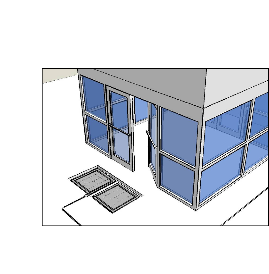
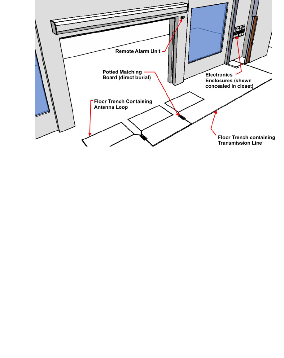
Figure 1-1: NGL Shielded FX System
NGL FX Installation Manual Rev. *
11 of 84
Chapter Overview
This chapter explains the system hardware and compares the two types of FX systems. This
general information is useful for planning and training purposes.
1. Hardware: Lists differences in hardware for the Shielded and Unshielded FX systems.
2. System Diagrams: Shows the basic layout of hardware components for each FX system.
Shielded vs. Unshielded FX System Hardware
Both Shielded and Unshielded FX systems are designed to be installed in the floor and provide an
invisible EAS system. The main difference between the shielded and unshielded versions is the in-
floor antenna assembly. Shielded FX system uses a metal floor pan and ferrite tiles, which prevent
the RF detection field from emitting downward into the floor or into the antenna panel itself.
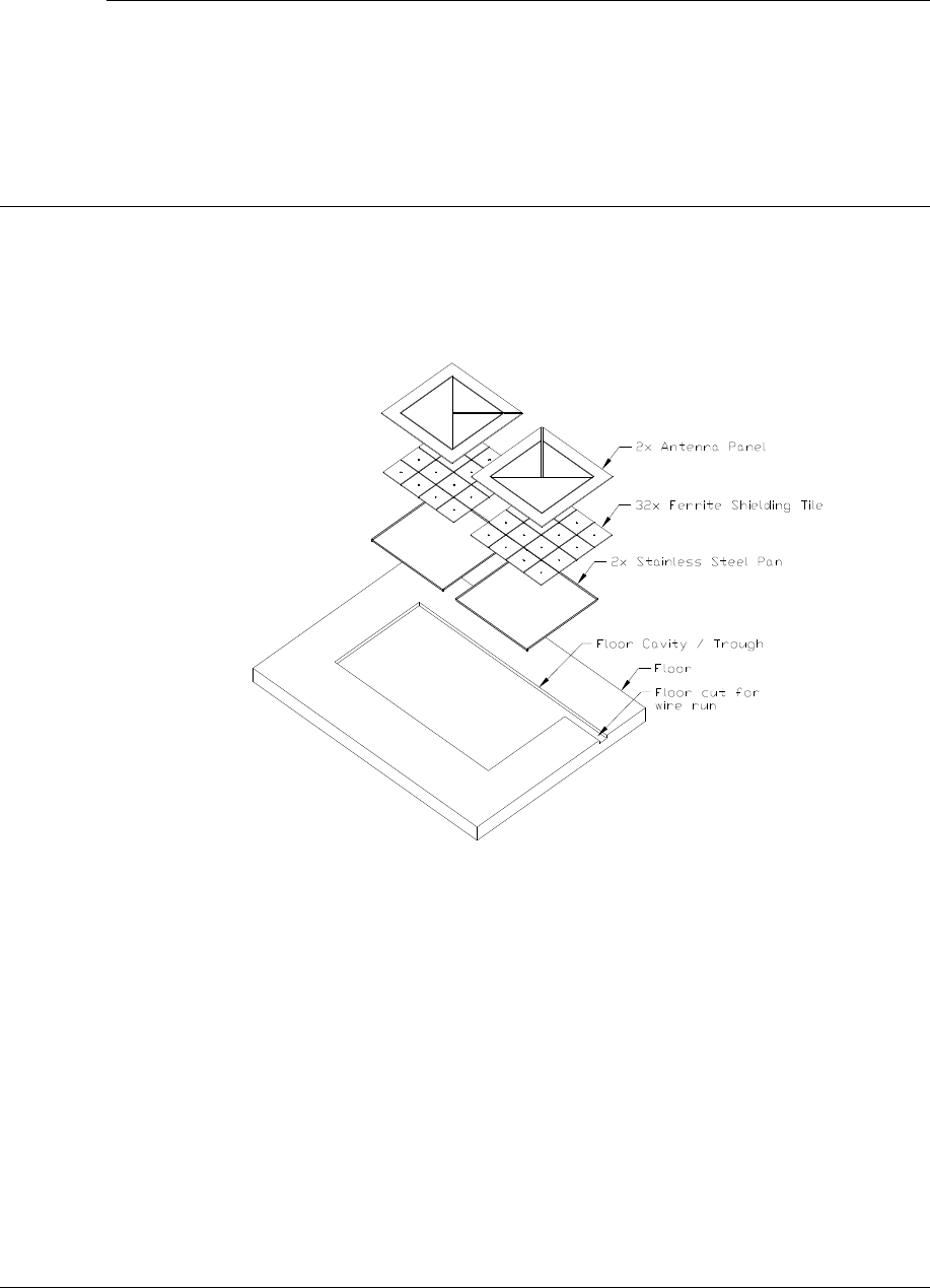
Figure 1-2: Shielded FX Antenna Layer Diagram
Both systems consist of a transceiver-based system using pulse/listen technology, allowing them
to work in a single antenna configuration. Some main hardware components are common to each,
specifically the electronics enclosure and transmission line. The antenna for the unshielded system
is a wire loop ran through Teflon tubing, whereas the antenna for the Shielded FX system is a pre-
assembled unit (see Figure 1-2 above).
With both systems, the antenna is wired directly to the Potted Matching Board, another component
that is installed in the floor (i.e. buried). The Potted Matching Board provides the link between the
antenna wiring and transmission line that connects to the remotely located electronics enclosure.
The electronics enclosure is designed to ensure proper ventilation in a non-condensing 0-40
O
C
environment. The wiring for the FX electronics system is a low-voltage, limited-energy system
(operating at 24VDC or less). All wiring must conform to applicable wiring codes.
NGL FX Installation Manual Rev. *
12 of 84
Shielded FX System Diagrams
FX 2012 Shielded systems use antenna assemblies which are comprised of a Stainless Steel pan,
ferrite shielding tiles, and PVC antenna panels. Figures 1.3 and 1.4 below show Shielded FX
installations of varying width covering 1.8m and 2.7m door openings [6ft and 9ft, respectively]:
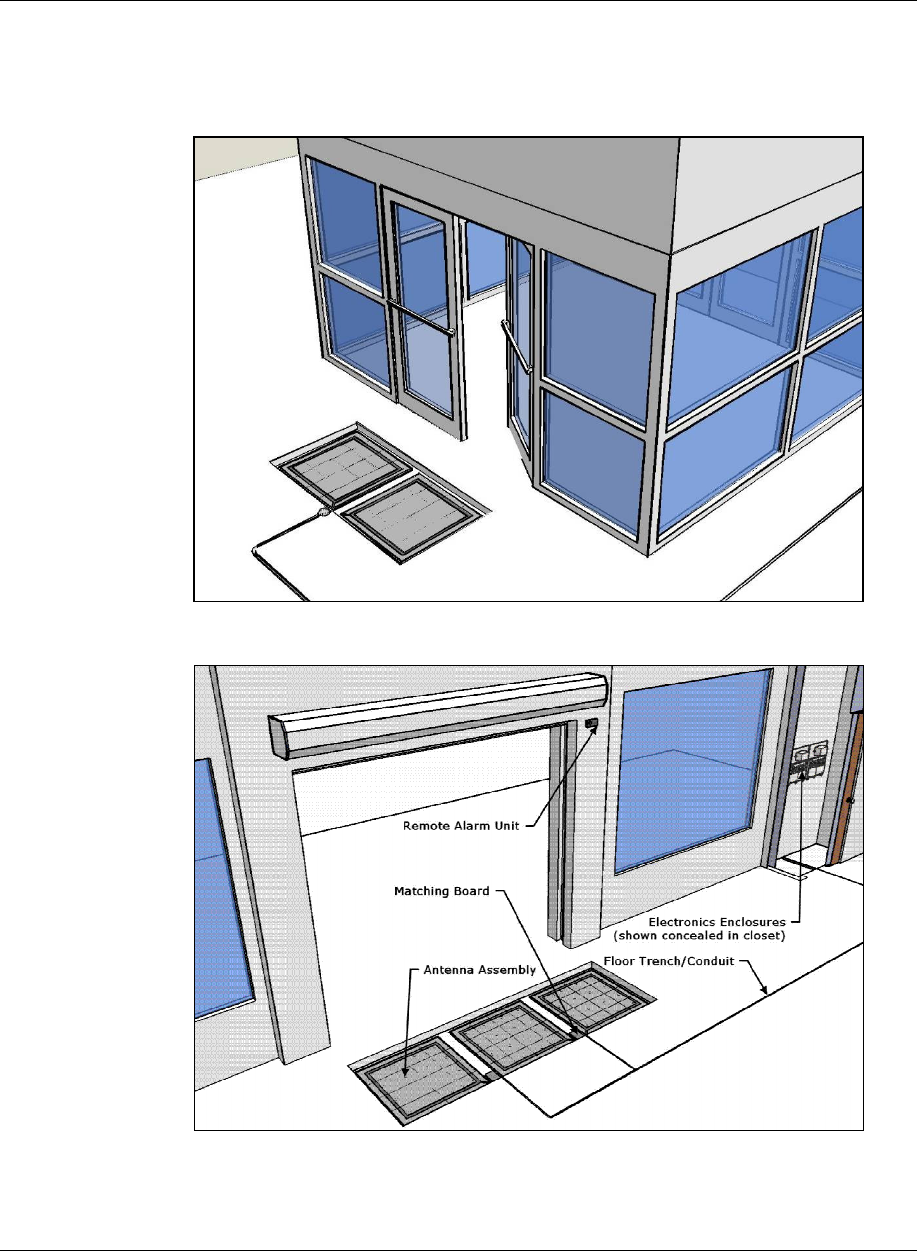
Figure 1.3: Typical Shielded FX 1.8m [6ft] Installation
Figure 1.4: Shielded FX 2.7m [9ft] Installation with Component Names
NGL FX Installation Manual Rev. *
13 of 84
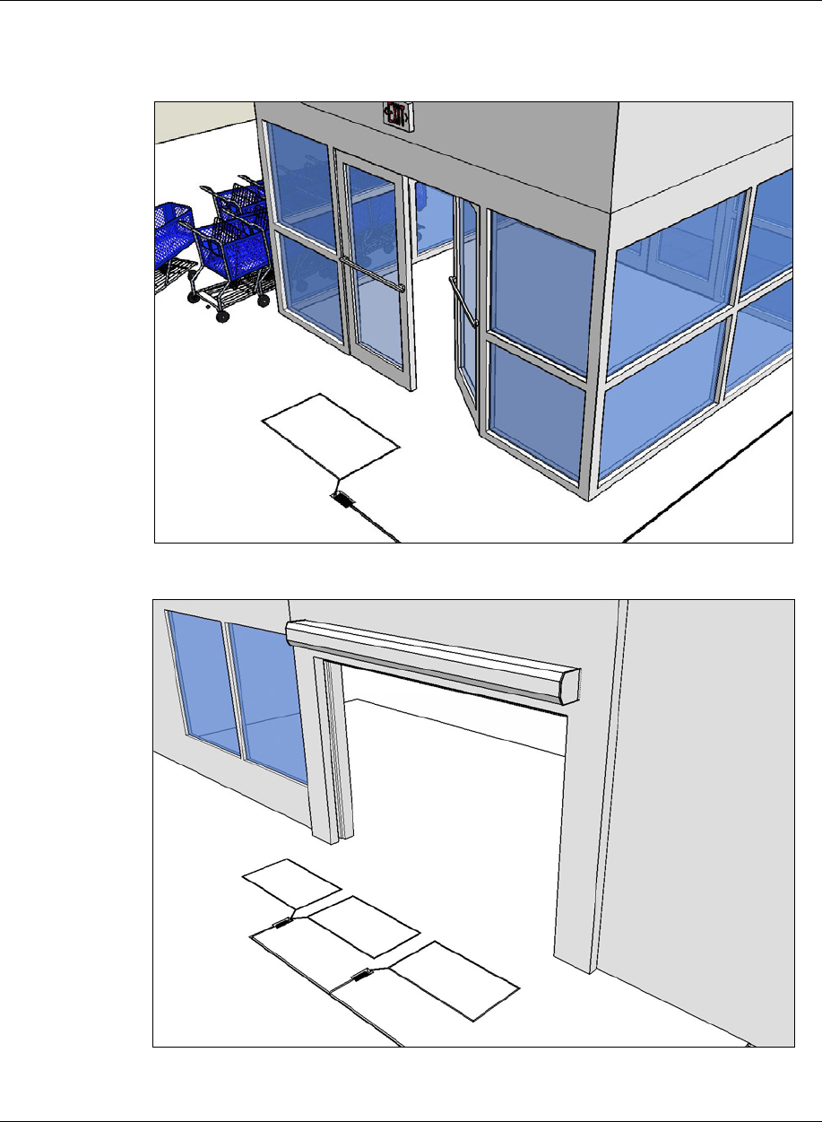
Unshielded FX System Diagrams
Figures 1.5, 1.6, and 1.7 display views of an installation for both 1.2m [4ft] and 3.6m [12ft] door
opening. Although not shown, a 1.8m [6ft] installation is also possible (see “Layouts”).
Figure 1.5: Typical Unshielded FX 1.2m [4ft] Installation
Figure 1.6: Typical Unshielded FX 3.6m [12ft] Installation
NGL FX Installation Manual Rev. *
14 of 84
Coverage width spans from 0.91m [3ft] to 4.88m [16ft] for both Unshielded and Shielded FX
systems. The 3.6m [12ft] door opening shown above is created by combining a 1.2m [4ft] and
2.4m [8ft] system together. Grouping multiple installation kits together is possible, but while
wider openings can be covered, it requires approval from Checkpoint’s Product Management and
confirmation of feasibility during the planning stage (refer to the “Site Survey”*** section below).
Figure 1.7: Typical Unshielded FX 3.6m [12ft] Installation with Components Names
NGL FX Installation Manual Rev. *
15 of 84
C H A P T E R
2
SITE PLANNING
Overview and Goals
Checkpoint Field Service personnel visit the location to perform a site survey before installation.
The initial planning stage is the appropriate time to determine site suitability, where the antenna
loops will be located (for maximum EAS protection) and the type of FX system to be installed.
Antenna Distance from Interfering Elements
Carefully execute antenna placement so environmental factors do not degrade system performance.
Reducing the chances that nearby elements could cause interfering effects before installation is
crucial. For repeatability, all measurements are given at baseline (i.e. using a standard tag type).
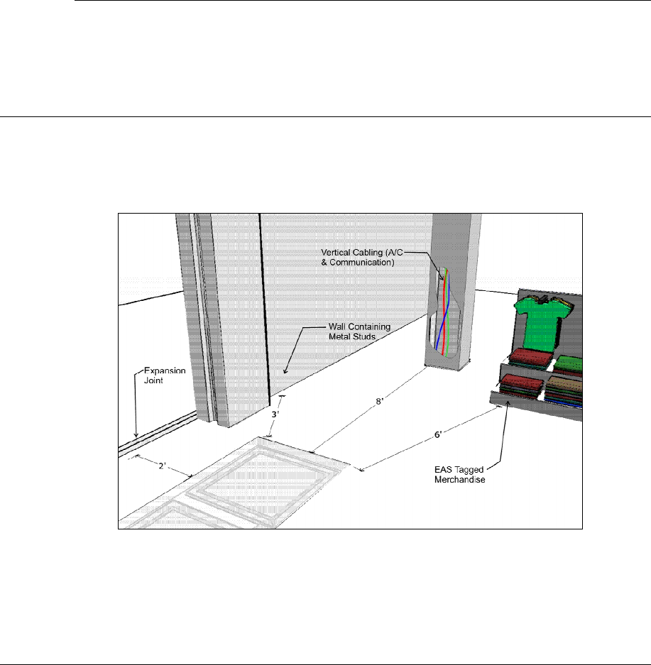
Figure 1.8: Distances from Interfering Elements
Note*: Figure 1.8 above shows a Shielded FX system, yet the common interfering elements and
the minimum allowable distance (from antenna to element) is the same for Unshielded FX systems.

NGL FX Installation Manual Rev. *
16 of 84
Common interfering elements and their minimum distances from an FX antenna are listed below:
Expansion Joints: The minimum distance from an expansion joint is 0.6 m [2 ft].
Vertical Cabling: The minimum distance from vertical cabling is 2.4 m [8 ft].
Metal Wall Studs: The minimum distance from a metal wall stud is 0.9 m [3 ft].
Inward and Outward Swinging Doors (Metal): The minimum distance from a manual
swinging metal door is 0.6 m [2 ft].
Note: The antenna must not be located below door when it is fully opened. Locate the FX
system components beyond the door – with a minimum clearance gap of 0.3 m [12 in].
Sliding Doors (Metal): The minimum distance from a metal sliding door is 1.2 m [4 ft]
Tagged Merchandise: The minimum distance from any tagged merchandise is 1.8 m [6 ft]
Note*: For details about location of other systems, such as CP IX/D11 Deactivators, that may
interfere with FX system operation, see appendix section X-Y***.
Determining the Electronics Location
FX antennas connect to the electronics enclosure, an integral device responsible for radio signal
control and alarm detection. This enclosure and its power supply are mounted remotely, and
environmental constraints must be taken into account. Determine an approximate location of the
electronics enclosure during the Site Survey.
Note*: The power supply can be mounted adjacent to the electronics enclosure, but this is not a
requirement.
Identify a location that is no further than 12.2m (40 linear-feet) or 15.2m (50 cable-feet) to allow
for bends in the conduit run. The electronics enclosure is usually wall-mounted approximately
1.8m [6ft] above the floor to reduce RF-interaction between the electronics enclosure and any
wiring in the ceiling or floor. Electronics mounted in the ceiling or rafters can potentially have a
high RF-interaction with the surrounding environment, and therefore, may not perform optimally.
Both the electronics enclosure and power supply are plenum-rated and can be installed above a
drop ceiling or in HVAC areas. Determined whether or not this is necessary during the site survey,
because the hood kit must be ordered separately. If the power supply is going to be located in the
plenum, the Power Supply hood kit must be installed by a licensed electrician (CKP P/N 7367100)
(GS-599MC-KIT(R).
***Note: Another option is to install the electronics enclosure in the plenum and locate the power
supply outside the plenum (below the drop ceiling).
During the following evaluation you can place the electronics enclosure and power supply on the
floor, but strive to locate the electronics near their final locations (to avoid unintended noise later).
Determining the Appropriate System Type
It is the responsibility of Checkpoint Field Service Personnel (and/or Project Management) to
identify environmental complications that would prevent any EAS system from being installed
and operating properly. After arriving at the site, evaluate the surroundings for possible locations
of in-ground antennas. Look for environmental factors that may affect the system, such as wiring,
lighting, and floor construction. In particular, metal pan flooring (slab on metal deck) will effect
RF detection; buildings with metal flooring are unlikely to be suitable for unshielded installations.
The procedure known as a “dry run” helps you determine if the less-costly Unshielded FX system,
which is more susceptible to noise, is the appropriate FX system type. Unshielded systems are
installed in situations where coupling to metallic objects in the floor is not an issue.

NGL FX Installation Manual Rev. *
17 of 84
***FX Performance
Environmental Considerations ***
FX systems are not approved for operation in a wet environment, so this procedure is meant for
dry installations only. The ideal location of the antenna(s) is where the water table does not
interfere (i.e. water drains away from in-floor assembly and does not pool above).
Note***: It is recommended that if the slab is on grade that the concrete be poured above a vapor
barrier to prevent moisture from rising, thus keeping the slab dry.
The store's architect will recommend the maximum permissible loading in the floor area where
FX-Shielded antenna panels are installed. The architect must consider such factors as anticipated
traffic over the floor and the material characteristics of the flooring (if covered above concrete).
The weight of the floor should not rest on the antenna(s).
The guidelines included in this guide assume installation into concrete (typical), but the antennas
may be placed above concrete if finished flooring, such as hardwood, laminate, tile or stone, will
conceal. With all installations, the concrete and other materials above the antenna(s) cannot be
metallic. For example, wire mesh cannot be used for reinforcement above the concrete. Tile grout
and the mortar used to fill the antenna trenches MUST BE non-metallic and non-magnetic grout.
As for the electronics, typical indoor environmental considerations must be met:
Operating temperature is 0°C to +40°C [32° to 104°F]. Permissible humidity range is 10 to 75%.
The UV Exposure requirement is the electronics enclosure must be located where it is not exposed
to direct sunlight. However, locating the enclosure where it will be exposed to sunlight through
glass is acceptable.
Perform a Dry Run
A “dry-run” can determine where potential problems might occur. The following procedure
simulates an FX antenna in place to ensure proper final configuration of the complete system:
1. Build the Floor Loop Jig. The device consists of a piece of cardboard that is 0.9m x 1.5m
[3ft x 5ft].
a. Cut out a rectangular piece of cardboard measuring 0.9m x 1.5m [3ft x 5ft].
b. Cut at least 14m [13.33ft] of 18 AWG Stranded wire, then form a rectangular loop
that measures 61cm x 112cm (24” x 44”). Approximately 0.3m [1ft] of excess wire
on both sides of the loop remains \.
c. Duct tape the loop to surface of the cardboard, centering it appropriately.
d. Allow extra wire to extend from the jig in the middle of one of the 61cm [24in] ends
of the rectangle or the corner. Twist together the two ends until it forms a braid. Do
not create more than 2 turns per 2.5 cm [2 turns per in].
2. Plug the loop terminals into X device. ***specifics to the connection or electronics contol
settings? Then power on the system. Test possible in-floor locations…
Content to work with***
Test by moving the Floor Loop Jig from opening to opening; shift from Side to side while
monitoring noise, see Chapter 6: Tuning*** until a suitable location is found.
Typical performance --- measurements , different detection heights…

NGL FX Installation Manual Rev. *
18 of 84
Based on the outcome of the dry run test (i.e. the level of noise when simulating an unshielded
system), the decision is made to test with a Shielded FX system or continue with the installation
(if results indicate it will perform optimally in the environment). To simulate Shielded FX system
operation, the entire antenna assembly (floor panel) is placed on the floor. Testing occurs as before.
Site Survey Conclusion
Overall, the site survey is an opportunity to gather details and share information required for the
proper installation workflow. Before leaving the test site, the location of the remote electronics,
conduit cuts and their layout (plans with exact dimensions), floor cuts or pre-installation space
requirements (see diagrams found in the “Physical Installation” sections), power outlet locations
(or hardwire into electrical). Coordinating with contractors facilitates easier installation.
Note*: It is strongly suggested for any new construction that the transmission line be ran through
conduit. Communicate with the contractor (or store personnel) before concrete has been poured.
Ensure wire run does not exceed the maximum distance to the electronics’ planned location. This
crucial action will allow the transmission line cable to be easily routed through the conduit.

NGL FX Installation Manual Rev. *
19 of 84
C H A P T E R
3
PHYSICAL INSTALLATION
Chapter Outline
This chapter offers diagrams and lists steps for physical installation of the major system hardware:
1. Requirements: Lists tool and part requirements for a typical installation.
2. Installation Outline: Lists all of the basic installation steps as a sequence.
3. Cut Diagrams: How to plan/make cuts for proper installation of the antenna assembly,
potted matching board, and install/route the wiring of the transmission line cable.
4. Mounting the Electronics Enclosure: Lists the basic steps for installing the enclosure.
Requirements
Tools
The following tools are required for FX system installations:
Arrow T-25 Staple Gun
Diagonal wire cutter
Hammer drill with 3/16” and 1/2” bits
Extension cord
Tape Measure
Hammer
Marker, Black Felt
Ratchet driver with 9/16” socket
Screwdrivers: mini, regular and #2 Phillips
Hacksaw
Utility knife
Wire Snake
Wire Strippers
Wrench, combination end 9/16”
TR4215 FX 2012 Installation Manual (This manual)
TR4215 Tuning Procedure (This manual)
Checkpoint Systems Field Service Diagnostic Management Software (DMS version
1.8.31 or later version) installed on a laptop with the appropriate cables. DMS is an
application developed to install and configure TR4215 boards via serial connections.
DMS provides for firmware updates without replacement of microchips.

NGL FX Installation Manual Rev. *
20 of 84
Parts
Quantity will vary according to site.
18 AWG 2-conductor (STP)
CAT5e cable
22 AWG 4-conductor (STP) (5594)
1/2” Anchor Bolts
*DekDuct (wire chase)
*Wiremold (1500 or 2600 series)
*Wiremold anchor bolts Note:
Note***: Wire routing methods will vary by installation.
Note***: Complete parts lists with OEM Part Numbers are included in the Appendix*** section
Part lists.
Installation Outline
Follow this sequence to successfully install the components and validate system operation:
1. Determine optimal antenna placement:
a. Perform a site survey now or
b. Use the results of a previous survey.
2. Determine power supply requirements and the ideal location for system electronics.
3. Physically install the antenna(s).
4. Connect the antenna wiring.
5. Install the peripherals.
6. Configure the system using DMS.
FX Antenna Installation
Antenna installation and tuning is performed by trained Checkpoint personnel. You have already
determined the number and size of the panels or ground loops, or you recently received this key
information from a prior survey. If you are unsure of any specifics, contact Checkpoint Project
Management.
Install the antenna(s) in the proper location(s) discovered during the site survey.
During Construction
In the event of a new construction, please convey the following information to the site contractors
(construction team foreman) or manager responsible for pouring the concrete:
• Location where antenna pan(s) will be placed (define a reference point).
• The exact dimensions of the pan(s); provide them with the “Floor Cut” diagrams below.
• The bury depth and length of the conduit (PVC), installed ahead of time, to route the
transmission cable.
After Construction
Convey the following instructions to the contractor for any existing sites (i.e. where cuts are made).
Refer to the diagrams from the appropriate “Floor Cut” sections corresponding to the required FX
system type and antenna configuration(s).
NGL FX Installation Manual Rev. *
21 of 84
Shielded FX Antenna Floor Cuts
Installing the FX antenna panels in an existing store requires a trough to be cut in the floor. If the
site is under construction, it is easier to mold the system into the floor (explained above). These
floor cut diagrams include the details on the size of the trough cuts required for each configuration.
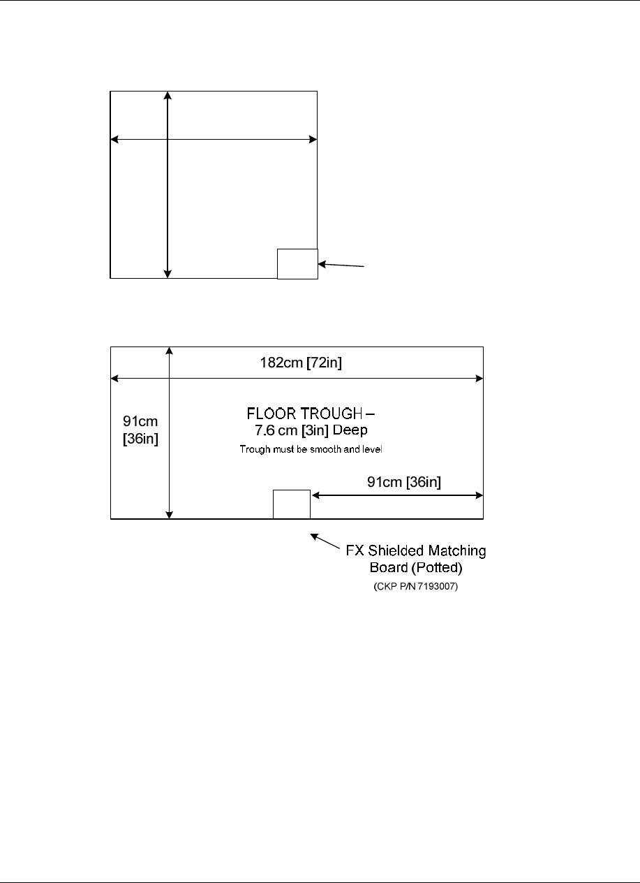
101.6cm [40in]
91cm
[36in]
FX Shielded Potted
Matching Board
(CKP P/N 7193007)
FLOOR TROUGH –
7.6 cm [3in] Deep
Trough must be smooth and level
Figure 5X***: FX Shielded w/Potted Matching Board for 0.9m [3ft] Opening
Figure 6X***: FX Shielded w/Potted Matching Board for 1.8m [6’] Opening
It is possible to create a wider system by combing either of the smaller two floor kits (Figures 3-1
and 3.2). For example, to cover a 2.7m [9’] mall opening, a 0.9m [3’] kit and a 1.8m [6’] kit would
be ordered. Figure 3-3 (on the following page) shows the required floor cuts when a single antenna
and double antenna are combined. Following that, two double antennas are installed side by side.
NGL FX Installation Manual Rev. *
22 of 84
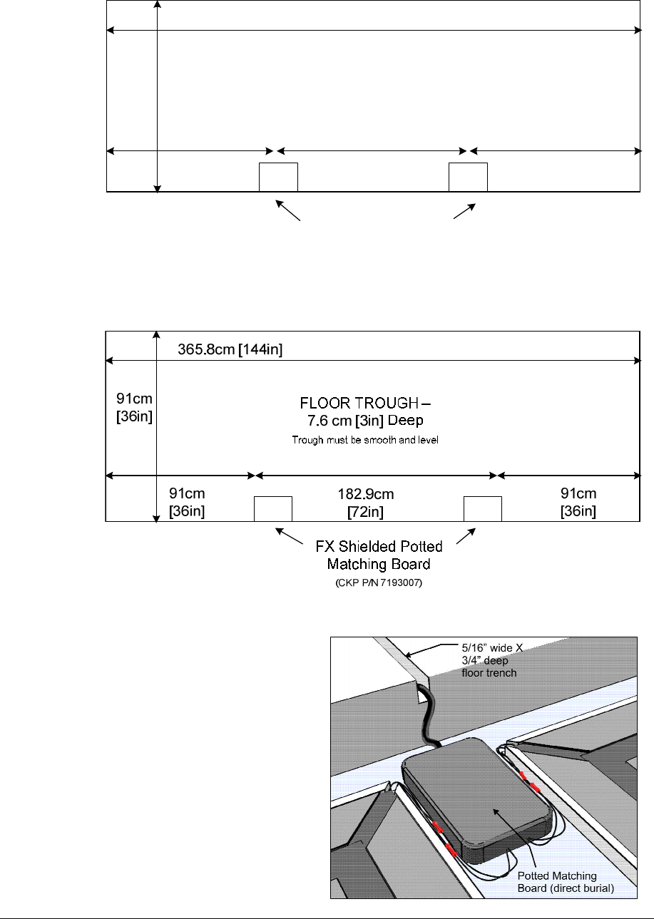
274cm [108in]
FLOOR TROUGH –
7.6 cm [3in] Deep
Trough must be smooth and level
FX Shielded Potted
Matching Board
(CKP P/N 7193007)
91cm
[36in]
91cm
[36in]
91cm
[36in]
91cm
[36in]
Figure 7X***: FX Shielded w/Potted Matching Board for 2.7m [9’] Opening
Figure 8X***: FX Shielded w/Potted Matching Board for 3.7m [12’] Opening
Figure 9: Shielded FX Matching
Board Placement
Note: The Potted Matching Board for
the multi-panel FX system must be
positioned between panels and not
outside (a different placement
compared to Unshielded systems).
NGL FX Installation Manual Rev. *
23 of 84
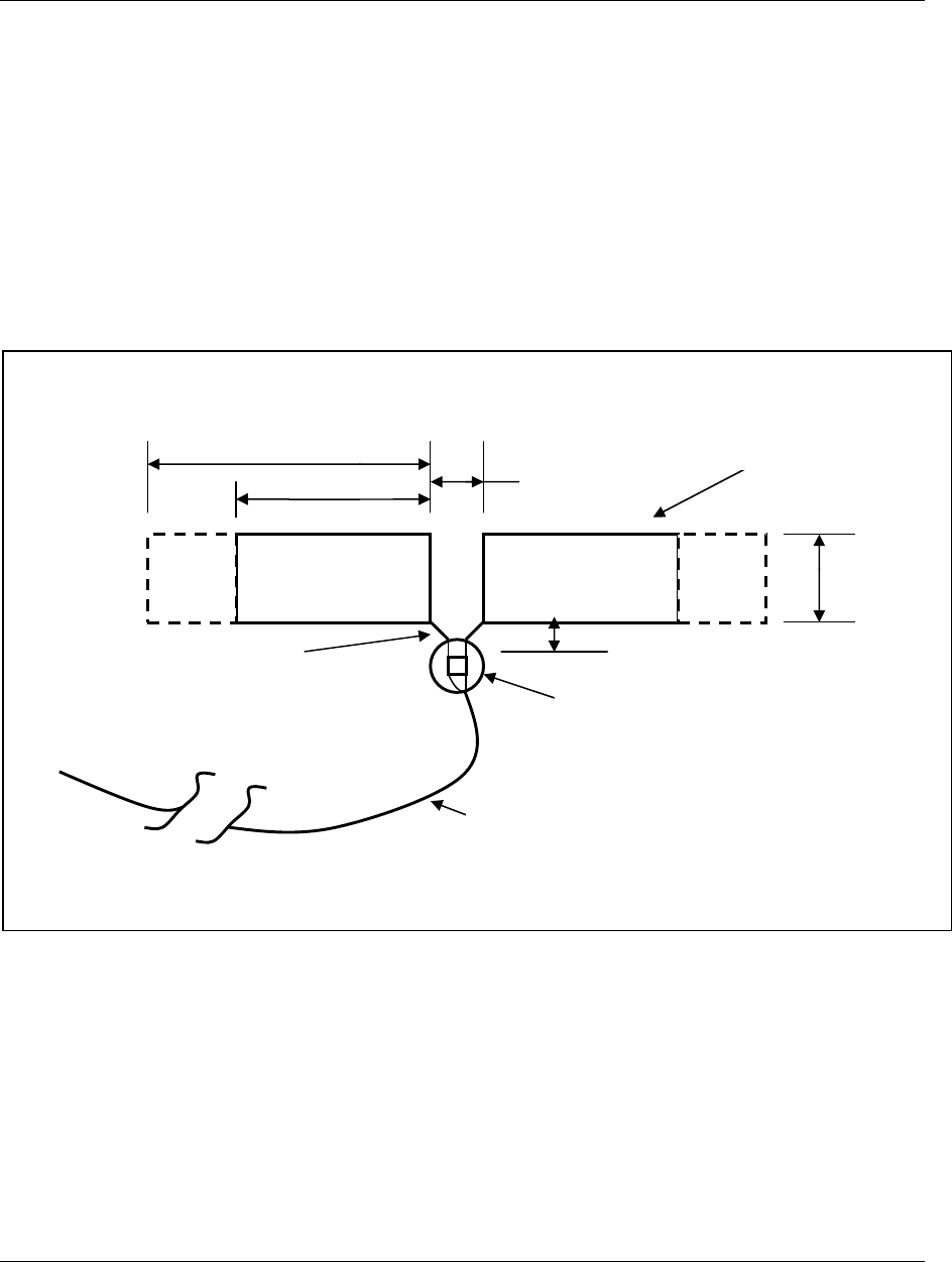
Unshielded FX Antenna Floor Cuts
There are three (3) NGL Unshielded FX kits available:
• Two Antenna
• Single Antenna
• Four Antenna
Determine the version to be installed and then work with the contractor. Use the appropriate
diagram to plan the floor cuts. Antenna floor cuts will measure approx. 5/16” wide and 3/4” deep
(0.79cm and 1.9cm, respectively) for the Unshielded FX system.
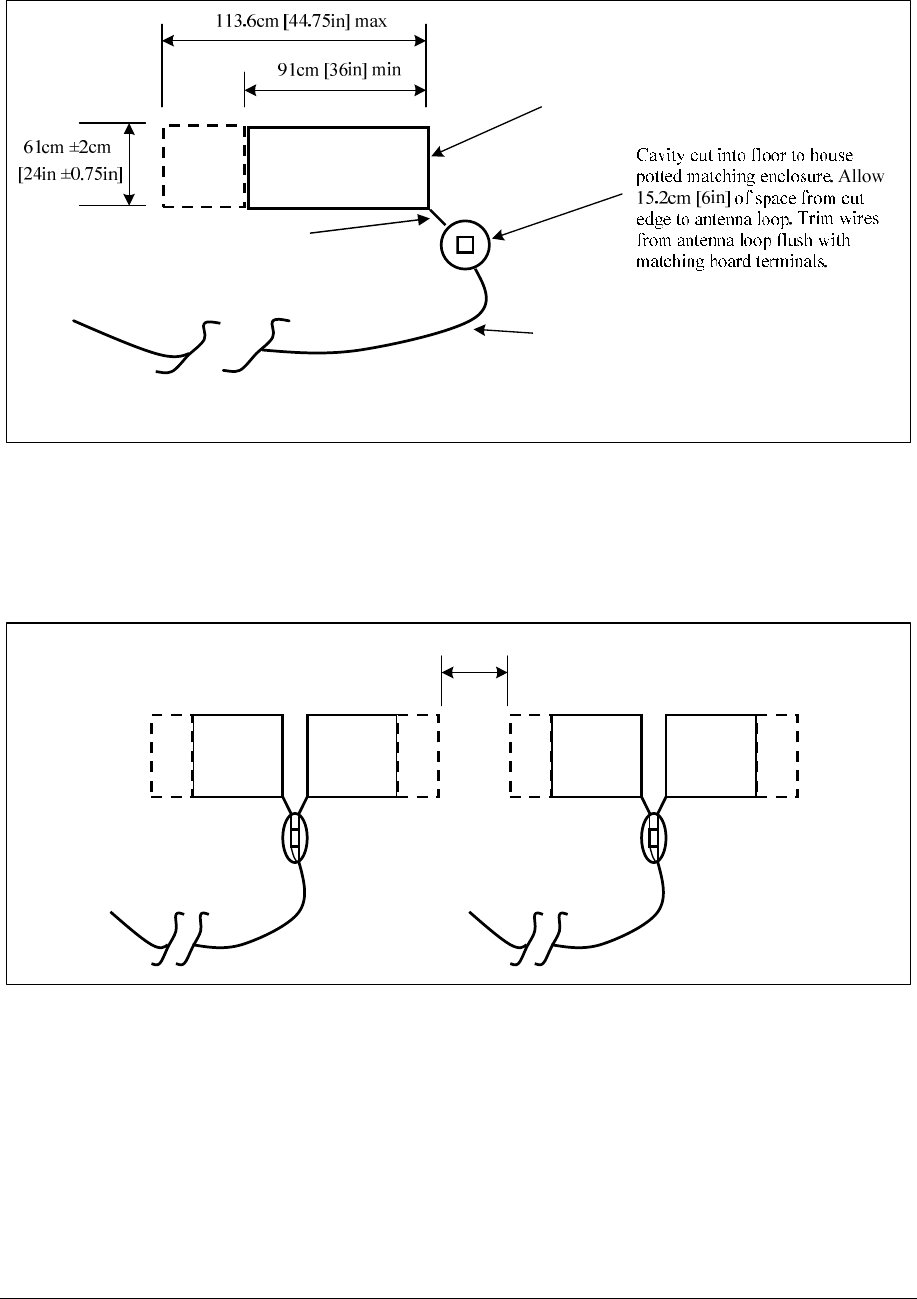
Note: The range for the antenna length dimension goes from 91.4cm [36in] minimum to 113.7cm
[44in] maximum.
Figure 23X***: Two-Antenna Installation
Note: The floor trench specifications for two-antenna Unshielded FX systems are above.
[
36in]
min
61cm
±
1.9cm
[24in ±0.75in]
113.7cm [44.75in]
max
20.3cm
[8in]
Cavity cut into floor to house potted
matching enclosure. Allow 15.2cm
[6in] of space from cut edge to
antenna loop. Refer to section X*
below for cutout dimensions.
15.24m (50’) of 100 Ω direct burial rated
transmission line to remote electronics.
Wire should remain at least 0.6m [2ft] from
the antenna wires. Install in conduit in new
construction (pass along instructions).
Location of Antenna Feedpoints
Excess is 30.5cm ± 2.5 cm [12in ± 1in] long.
Dress wires on top of each other in floor cut
and seal ends of tubing with hot glue.
Antenna wire, including feed
point, is encapsulated in a single
length of Teflon tubing
.
91.4cm
NGL FX Installation Manual Rev. *
24 of 84
Figure 24X***: Single-Antenna Installation
Note: The floor trench specifications for a single-antenna Unshielded FX system are shown above.
Note: Details on how the components are installed are written (on the specific parts) shown above. Please see notes
on transmission line cable routing and conduit as note (complete instructions on wiring are found in “Wiring”).
20.3cm [8in] spacing to adjacent loop
Figure 25X***: Four-Antenna Installation
NOTE*: These kits can be combined to create larger systems. For example, to cover a 12 ft
opening, a 4 ft kit and an 8 ft kit would be ordered.
Antenna wire, including feed
point, is encapsulated in a single
length of Teflon tubing
.
15.24m [50ft] of 100 Ω direct burial rated
transmission line to remote electronics.
Wire should remain at least 0.6m [2ft] from
the antenna wires. Install in conduit in new
construction (pass along instructions).
Location of Antenna Feedpoint
Excess is 30.5cm ± 2.5 cm [12in ± 1in] long.
Dress wires on top of each other in floor cut
and seal ends of tubing with hot glue.
NGL FX Installation Manual Rev. *
25 of 84
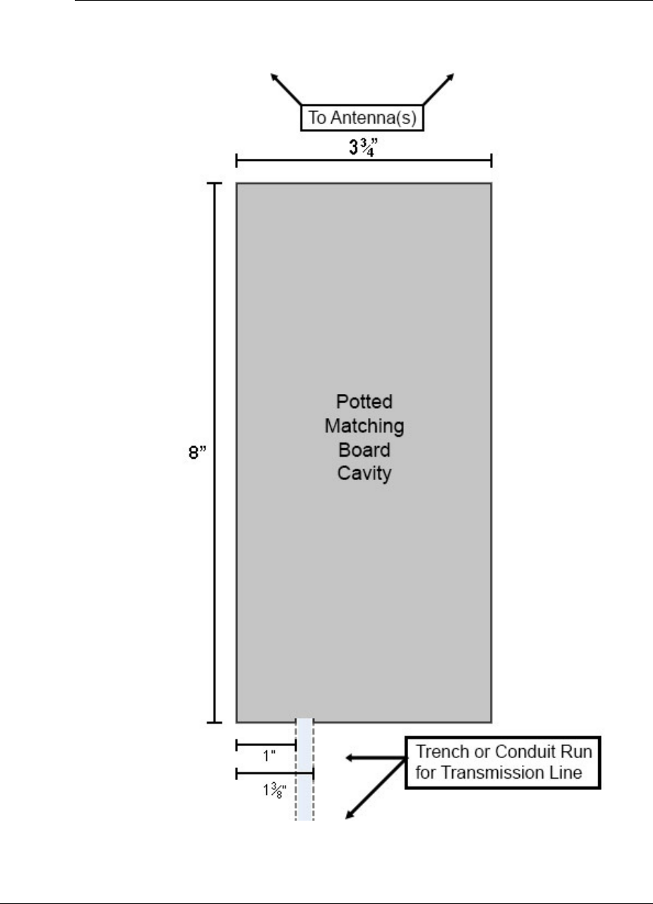
Potted Matching Board Cuts – Unshielded FX Only
The cavity for the potted matching PCB is to be placed 15.2cm [6in] from the antenna
loops, centered between them. Plan the cuts for this cavity using the specifications below:
Figure X***: Potted Matching Board Cavity
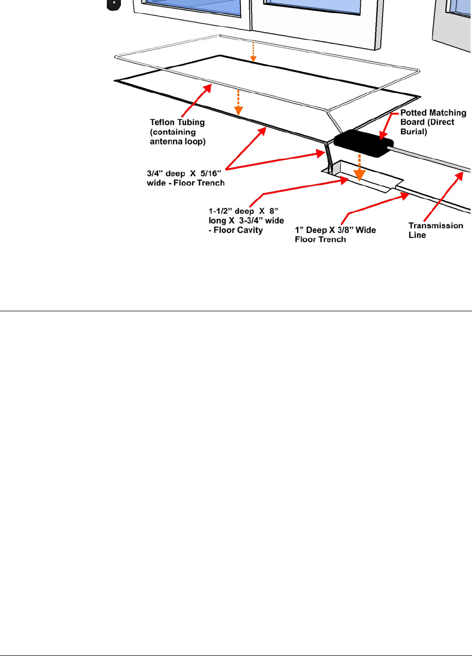
NGL FX Installation Manual Rev. *
26 of 84
Figure X***27: Unshielded Floor Trench Specifications
Mounting the Electronics Enclosure
Instructions for locating the Electronics Enclosure are included below.
It is important that the electronics enclosure be located no further than 12.2 linear-meters
[40 linear-feet] from the antenna panels to allow for bends in the 15.2 cable meters [50 cable feet]
run. The enclosure, which weighs 5.17kg [11.4lbs], has keyhole slots at its edges to facilitate
mounting to the wall surface. The mounting hardware can support the weight of the unit. Do not
mount the electronics enclosure beneath potential water sources (e.g. a sprinkler or pipe).
The enclosure must have 2.5cm [1 in] clearance on all sides. It is suggested to locate the enclosure
directly over (or nearest to) the conduit’s end wire as possible, ensuring the cable length is kept to
a minimum. Limiting exposed cable prevents interference (but do not cut, see “Transmission
Line,” and “Wrapped Cable” section). Use schedule 40 PVC conduit (contractor supplied) or wire
run, such as Checkpoint approved Dek Duct, to route the cable.
Installation procedures are listed for each type of material on which the enclosure can be installed:
• Wood Surface,
• Drywall, and
• Concrete.
NGL FX Installation Manual Rev. *
27 of 84
Wood Surface Installation
For mounting to wood, use a #7 x ½” (0.38cm x 1.3cm) hex head screw (CKP P/N 7939172).
Figure X***: Wood Surface Installation
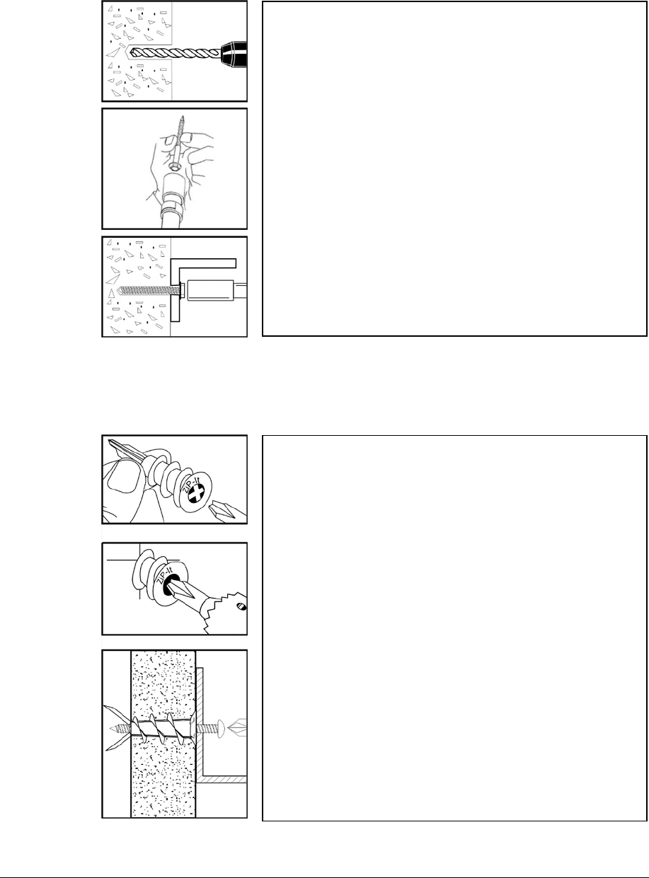
Drywall Surface Installation
For mounting to drywall, use a #8 x 1” (0.42cm x 2.5cm) panhead screw (CKP P/N 7308823),
which is a Power Fastener Zip-it (P/N 02348).
Figure X***: Drywall Installation
Using the proper diameter bit, drill a hole into the base
material to a depth of at least 0.6cm [1/4”] deeper than
the embedment required. Blow the hole clean of dust
and other material.
Select the installation tool and drive socket to be used.
Insert the head of the screw into the hex head socket
driver.
Place the point of the screw through the fixture into
the pre-dilled hole and drive the anchor in one steady
continuous motion until it is fully seated at the proper
embedment.
Insert either # 2 or # 3 Phillips driver bit into the
recess of the ZiP-It anchor head. Use a manual
screwdriver or a low-rpm battery-powered electric
screw gun.
Push the ZiP-It anchor into the surface of the
wallboard until the two cutting blades penetrate the
surface. Using gentle forward pressure, rotate the
ZiP-It until the collar sets flush to the surface of the
wall.
Put the fixture in place, insert screw and tighten until
it feels secure. As the screw is threaded into the nylon
versions, the point will expand resulting in increased
load capacity in thicker wallboard.
Note: When using an electric screw gun for
application, set clutch and use slow speed (do not
exceed approximately 300-400 RPM).
NGL FX Installation Manual Rev. *
28 of 84
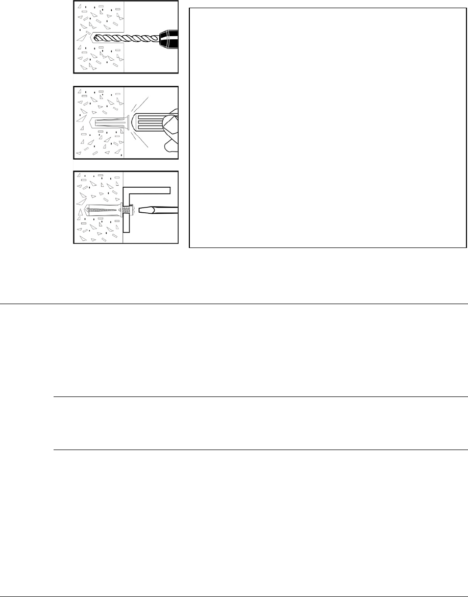
Concrete Surface Installation
For mounting to concrete, use a 5/16” lead anchor and a #12 x 1 ½” panhead screw (CKP P/N
366291). Lead anchor (0.79cm) is a Power Fastener (P/N 09439). Screw is 0.55cm x 3.8cm.
Figure X***: Concrete Installation
Mounting the Power Supply
The power supply can be mounted near the electronics enclosure or, by space requirements, in
another remote location. If the power supply is installed above a drop ceiling or in the plenum
(HVAC ventilation), the Above Ceiling Conversion Kit must be ordered in advance.
For the unit’s weight and dimensions, refer to the Appendix “Power Supplies” section.
GS-599ES(R) Installation
Hold the unit in place and mark the screw hole locations. Secure the power supply in its intended
location using the same instructions found above (refer to “Mounting the Electronics Enclosure”).
GS-599MC-KIT(R) Installation
Refer to Appendix 1 for the complete hood kit instructions.
Drill a hole into the base material to the depth
required. The tolerances of the drill bit used should
meet the requirements of ANSI Standard B212.15.
Blow the hole clean of dust and other material. Insert
the anchor into the hole until the flange is seated flush
with the surface of the base material.
Position the fixture. Insert the screw tip through the
fixture into the anchor and tighten.

NGL FX Installation Manual Rev. *
29 of 84
C H A P T E R
4
WIRING
Overview
This chapter instructs on the wiring of the entire floor system, beginning with the FX antenna and
potted matching board* wiring, then moving to the transmission line and its proper connection to
the electronics enclosure. Figures show the proper wiring of the A1111 Interface Board and DC
Power Supply. Lastly, the system-specific (sync, IPC and alarm group) wiring schemes are shown.
W
ARNING
*:
This system uses TR4215
†
electronics with firmware version 4.00 or higher. It is
critical to note that ONLY TR4215 electronics can be used in conjunction with this system.
It is also critical that DMS version 1.8.31 or later be used to configure the system.
The outline below is a sequence of the FX system wiring procedures.
1. Antenna Wiring
a. Wiring the Shielded FX Panel to the Potted Matching Board
b. Wiring the Unshielded FX antenna to the Potted Matching Board
2. Electronics Chassis
a. Transmission Line Wiring to the A1111 board
b. DC Power Supply wiring
c. Sync and Alarm Group ***waiting for info
d. Lights and Sounder
e. Inter-pedestal communication

NGL FX Installation Manual Rev. *
30 of 84
Antenna Wiring
Recall the Potted Matching Board installation and wiring differs between Shielded and Unshielded
FX systems. Instead of locating it in a separate cavity, the Shielded FX matching board is placed
in the top center between the assemblies (or directly beside it, for a single loop). After successful
hardware installation, the next step is wiring the antenna(s) to the matching board.
Shielded FX Antenna
Figure X below shows the proper wiring of the Shielded FX system.
***Graphic of Shielded system wired to PMB.
Figure X***28: Shielded FX system Antenna Panel
Note: If this is a single loop configuration, use the right pair of short and long antenna wires for
the loop (right wires are with potting material facing up and wires exiting the potted matching
assembly towards you). Trim the unused antenna wires at the potted matching board assembly.
Wiring the Potted Matching Board
Perform the following to wire the Potted Matching Board (CKP P/N 7193007) to the Shielded FX
antenna system:
1. Connect the antenna wire to the 0.3m [1ft] wire adjacent to it (wire on the right side of the
potted matching board with the potting side up) in the potted matching assembly using one of
the provided wire nuts.
2. Strip the wire leads about 1.2cm (½”). Next, without pre-twisting the leads, align the wire
conductors and then twist a wire nut onto each connector until hand tight.
3. Apply excess sealant in and around conductors. This forms a tight connection that will not fail
once buried in the concrete. Refer to the “FX Antenna Floor Cuts” section for details on the
placement of the potted matching board.
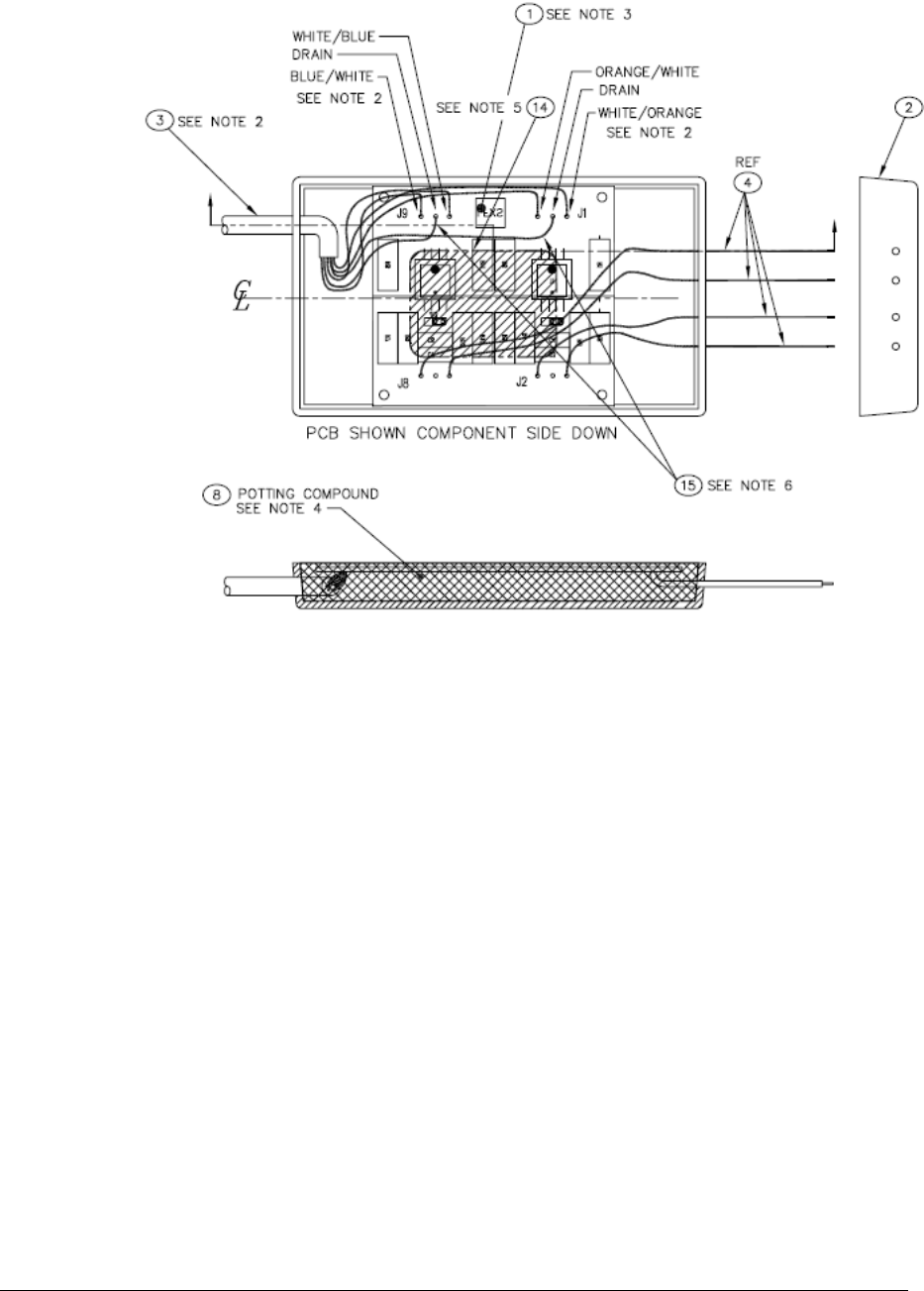
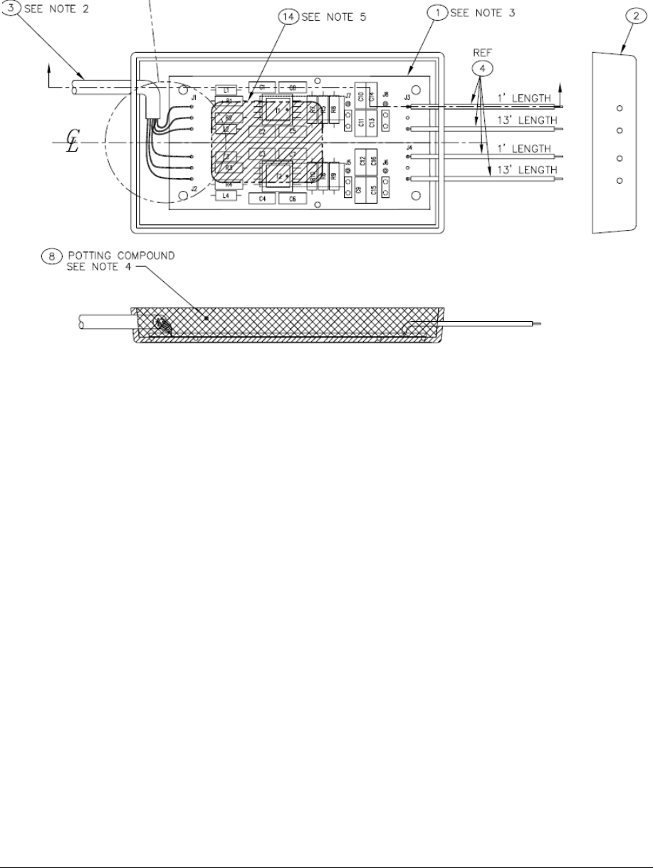
The external and internal wiring before potting of the matching board (P/N 7193007) is displayed
in Figure X***. Item 3 is the 15m [50ft] cable coming from the interface board. Item 4 displays
the connections from J8 and J2 which are connected to the FX antenna. The fly wires from these
ports are 0.3m [1ft] in length.
NGL FX Installation Manual Rev. *
31 of 84
Figure 18: Shielded Potted Matching Board Wiring
NGL FX Installation Manual Rev. *
32 of 84
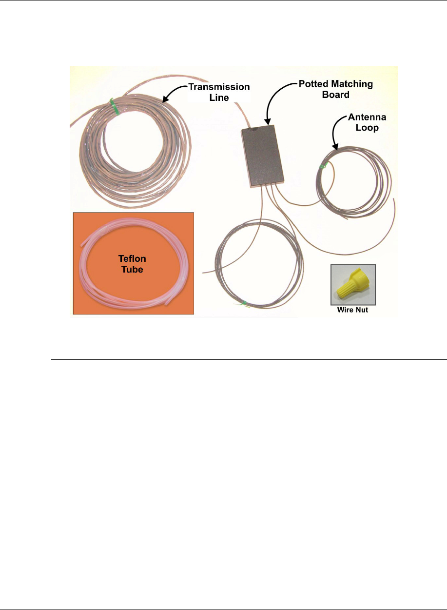
Unshielded FX Antenna
The component list and wiring instructions for connecting the Unshielded FX system antenna loop
to the potted matching board are below. Figure X***29 details the unshielded potted matching
board’s electrical connections before potting is done.
Figure X***: Potted Matching board and Unshielded FX Antenna Loop Components
Wiring the Potted Matching Board
Please note the placement of the potted matching board 15.24cm [6in] in front of the antenna
instead of in between the antenna. The matching board for the Unshielded FX system has a
different part number (CKP P/N 7113880), but has the same physical dimensions.
1. Determine the length of wire to be cut for antenna loop configuration(s). Cut long if unsure.
2. Insert the cross linked polyethylene-jacketed wire through the Teflon tubing. Allow the excess wire to stick
out at either end of the tubing.
3. Starting about 3.8cm [1.5in] from the potted matching assembly, place the tubing in the cut trough.
4. Install the wire in the trench, feeding it around until the loop is complete. The antenna feed point will be
30.5cm +/- 2.5cm [12in +/- 1in] when trimmed. No extra wire is allowed because it may affect tuning.
Note*: The Teflon tubing should be one continuous piece beginning at the assembly, through the cut for the
pigtail, through the antenna loop cut, and back through the pigtail cut. One tube is positioned above the
other at the pigtail location.
Note*: Keep exposed wire (not in Teflon tubing) to a minimum leaving just enough to allow the wire nuts
to be installed. The exposed wire should measure approximately 3.81 cm [1.5in].
5. Next, seal the ends of the Teflon tubing completely with hot glue to prevent the infiltration of concrete or
moisture.
NGL FX Installation Manual Rev. *
33 of 84
Figure X***29: Unshielded Potted Matching Board Wiring
Note: If this is a single loop configuration, the pair of short and long antenna wires on the right
(see FigureX***) are wired to the antenna loop. As shown in the graphic, the potting material side
faces up and the wires exit the assembly (towards you). The unused antenna wires are trimmed
(see step 4 below).
NGL FX Installation Manual Rev. *
34 of 84
TR4215 Components and Enclosure
Overview
Connections to the Electronics Enclosure / reader assembly are listed below. This section
describes how to prepare and wire all cables and wires involved in the antenna installation.
TR4215 board with all interfaces labeled. A ferrite clip (CKP P/N 7284760) (Fair Rite P/N
044380640) is installed on all TR4024 I/O cables shown below.
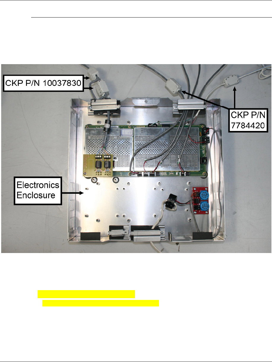
Figure 11: Electronics Enclosure panel
Connector type: Riacon, 4 terminal
Cable type: 22 AWG, 4-conductor with drain wire