Cisco Linksys WRT55AG Dual-Band Wireless A+G Broadband Router User Manual WRT55AG ug Rev NC
Cisco-Linksys, LLC Dual-Band Wireless A+G Broadband Router WRT55AG ug Rev NC
Contents
User manual part 4
Dual-Band Wireless A+G Broadband Router
5GHz, 802.11a (WEP)
The 5GHz, 802.11a (WEP) screen, shown in Figure 7-9, allows you to config-
ure your 5GHz,
802.11a WEP
settings. WEP
encryption
should always
be enabled to
increase the
security of your
wireless net-
work.
Default Transmit Key Select which WEP key (1-4) will be used when the
Router sends data. Make sure the receiver is using the same key.
WEP Encryption Keys 1-4 offer 64-bit, 128-bit, or 152-bit encryption; select
the type of encryption you want from the drop-down box. To disable WEP
Encryption, select Disable.
Passphrase (Complete this field when using 64-bit or 128-bit encryption.)
Instead of manually entering WEP keys, you can enter a Passphrase. This
Passphrase is used to generate one or more WEP keys. It is case-sensitive and
should not be longer than 16 alphanumeric characters. This Passphrase function
is compatible with Linksys wireless products only. [If you want to communi-
cate with non-Linksys wireless products, enter the WEP key(s) manually on the
non-Linksys wireless products.] After you enter the Passphrase, click the
Generate button to create WEP keys.
Keys 1-4 WEP keys enable you to create an encryption scheme for wireless
LAN transmissions. Manually enter a set of values. (Do not leave a key field
blank, and do not enter all zeroes. These are not valid key values.) Keys 1-4
offer 64-bit, 128-bit, or 152-bit encryption.
If you are using 64-bit WEP encryption, then the key must be exactly 10 hexa-
decimal characters in length. If you are using 128-bit WEP encryption, then the
key must be exactly 26 hexadecimal characters in length. If you are using 152-
bit WEP encryption, then the key must be exactly 32 hexadecimal characters in
length. Valid hexadecimal characters are “0”-“9” and “A”-“F”.
41
Figure 7-9
Instant Wireless®Series
5GHz, 802.11a
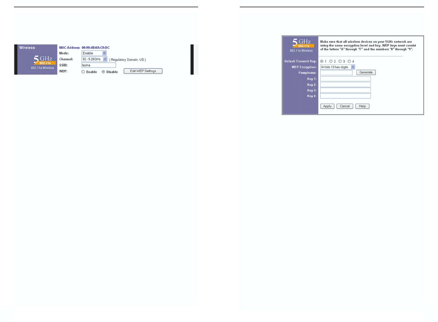
The 5GHz, 802.11a portion of the Setup screen, shown in Figure 7-8, allows
you to configure your 5GHz, 802.11a wireless network settings.
Mode If you do not have any 802.11a devices in your network, you can dis-
able this broadcasting by selecting Disable.
Channel Select the appropriate channel from the list provided to correspond
with your network settings, between 36 and 64. All devices in your wireless
network must use the same channel in order to function correctly. If you want
the Router to automatically scan for a clear channel, then click the checkbox.
SSID The SSID is the network name shared among all points in a wireless
network. The SSID must be identical for all points in the wireless network. It
is case-sensitive and must not exceed 32 characters (use any of the characters
on the keyboard). Make sure this setting is the same for all points in your wire-
less network. For added security, you should change the default SSID (linksys)
to a unique name.
WEP (Encryption) An acronym for Wired Equivalent Privacy, WEP is an
encryption method used to protect your wireless data communications. WEP
uses 64-bit, 128-bit, or 152-bit keys to provide access control to your network
and encryption security for every data transmission. To decode a data trans-
mission, each device in a network must use an identical key. Higher encryption
levels offer higher levels of security, but due to the complexity of the encryp-
tion, they may decrease network performance. To enable WEP, click the radio
button beside Enable. Click the Edit WEP Settings button to configure the
WEP keys for your 5GHz, 802.11a wireless network (see Figure 7-9).
Check all the values, and click the Apply button to save your 5GHz, 802.11a
settings. To cancel any changes you’ve entered on this page, click the Cancel
button. To get more information about the features, click the Help button.
40
Figure 7-8
Dual-Band Wireless A+G Broadband Router
4342
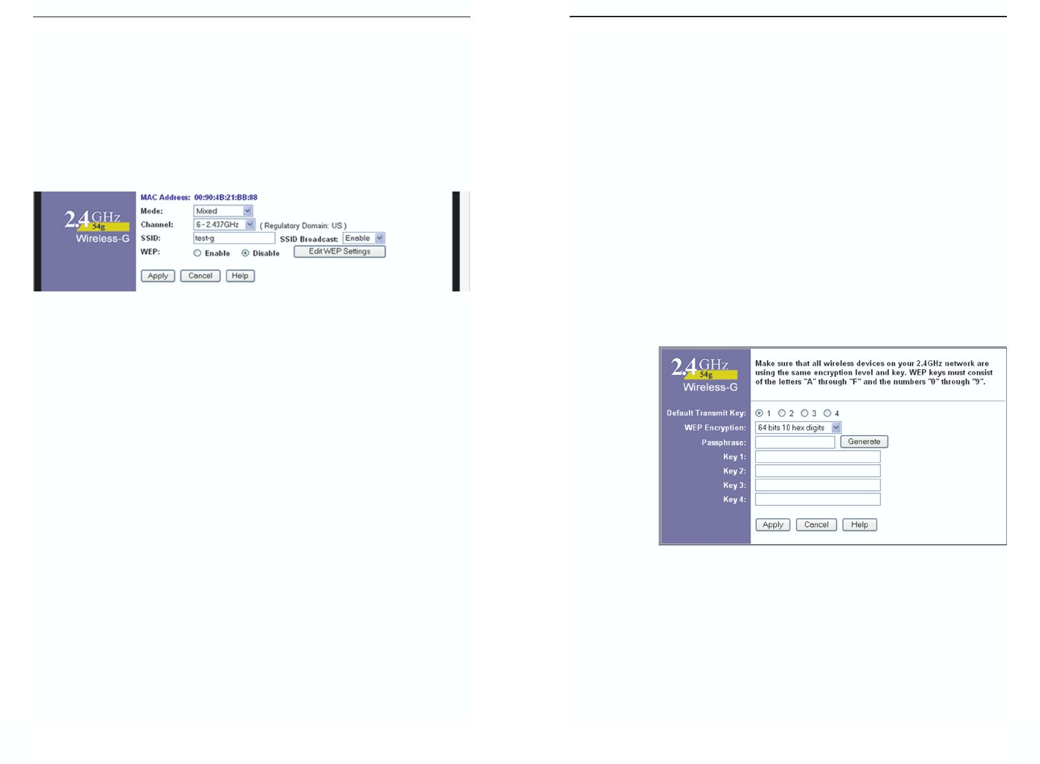
WEP (Encryption) An acronym for Wired Equivalent Privacy, WEP is an
encryption method used to protect your wireless data communications. WEP
uses a combination of 64-bit or 128-bit keys to provide access control to your
network and encryption security for every data transmission. To decode a data
transmission, each device in a network must use an identical 64-bit or 128-bit
key. Higher encryption levels offer higher levels of security, but due to the
complexity of the encryption, they may decrease network performance. To
enable WEP, click the radio button beside Enable. Click the Edit WEP
Settings button to configure the WEP keys for your 2.4GHz, Wireless-G net-
work (see Figure 7-11).
Check all the values, and click theApply button to save your 2.4GHz, Wireless-
G settings. To cancel any changes you’ve entered on this page, click the Cancel
button. To get more information about the features, click the Help button.
2.4GHz, 54g/Wireless-G (WEP)
The 2.4GHz, 802.11b (WEP) screen, shown in Figure 7-11, allows you to con-
figure your 2.4GHz, Wireless-G WEP settings. WEP encryption is recom-
mended to
increase the
security of
your wireless
network.
Default Transmit Key Select which WEP key (1-4) will be used when the
Router sends data. Make sure the receiver is using the same key.
WEP Encryption Keys 1-4 offer 64-bit or 128-bit encryption; select the type
of encryption you want from the drop-down box. To disable WEP Encryption,
select Disable.
Figure 7-11
Instant Wireless®Series
Check all the values, and click the Apply button to save your 5GHz, 802.11a
WEP settings. To cancel any changes you’ve entered on this page, click the
Cancel button. To get more information about the features, click the Help but-
ton.
2.4GHz, 54g/Wireless-G
The 2.4GHz, 802.11g-draft portion of the Setup screen, shown in Figure 7-10
allows you to configure your 2.4GHz, Wireless-G wireless network settings.
Mode If you have Wireless-G and 802.11b devices in your network, then keep
the default setting, Mixed. If you have only Wireless-G devices, select G-Only.
If you do not have any Wireless-G and 802.11b devices in your network, select
Disable.
Channel Select the appropriate channel from the list provided to correspond
with your network settings, between 36 and 64. All devices in your wireless
network must use the same channel in order to function correctly. If you want
the Router to automatically scan for a clear channel, then click the checkbox.
SSID The SSID is the network name shared among all points in a wireless
network. The SSID must be identical for all points in the wireless network. It
is case-sensitive and must not exceed 32 characters (use any of the characters
on the keyboard). Make sure this setting is the same for all points in your wire-
less network. For added security, you should change the default SSID (linksys-
g) to a unique name.
SSID Broadcast When wireless clients survey the local area for wireless net-
works to associate with, they will detect the SSID broadcast by the Router. To
broadcast the Router's SSID, keep the default setting, Enable. If you do not
want to broadcast the Router's SSID, then select Disable.
Figure 7-10
Dual-Band Wireless A+G Broadband Router
4544
L2TP - Layer Two Tunneling Protocol is an extension of the Point-to-Point
Tunneling Protocol (PPTP) used by to enable the operation of a virtual pri-
vate network (VPN) over the Internet.
PPTP - Point-to-Point Tunneling Protocol is the method used to enable
VPN sessions to a Windows NT 4.0 or 2000 server. To allow PPTP tunnels
to pass through the Router, PPTP Pass-Through is enabled by default. To
disable PPTP Pass-Through, uncheck the box next to PPTP.
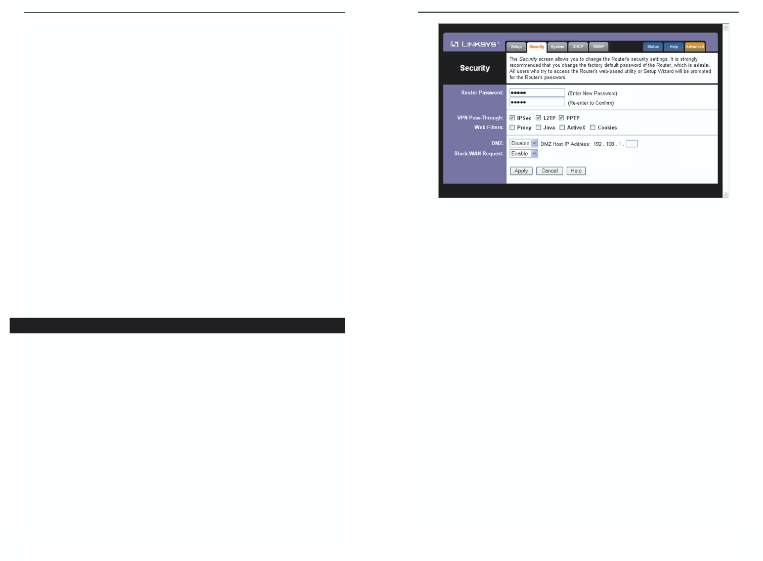
Web Filters Using the Web Filters feature, you may enable up to four specif-
ic filtering methods.
Proxy - Use of WAN proxy servers may compromise the Router's security.
Denying Proxy will disable access to any WAN proxy servers. To enable
proxy filtering, click the Proxy box.
Java - Java is a programming language for websites. If you deny Java, you
run the risk of not having access to Internet sites created using this pro-
gramming language. To enable Java filtering, click the Java box.
ActiveX - ActiveX is a programming language for websites. If you deny
ActiveX, you run the risk of not having access to Internet sites created using
this programming language. To enable ActiveX filtering, click the ActiveX
box.
Figure 7-12
Instant Wireless®Series
Passphrase Instead of manually entering WEP keys, you can enter a
Passphrase. This Passphrase is used to generate one or more WEP keys. It is
case-sensitive and should not be longer than 16 alphanumeric characters. This
Passphrase function is compatible with Linksys wireless products only. [If you
want to communicate with non-Linksys wireless products, enter the WEP
key(s) manually on the non-Linksys wireless products.] After you enter the
Passphrase, click the Generate button to create WEP keys.
Keys 1-4 WEP keys enable you to create an encryption scheme for wireless
LAN transmissions. Manually enter a set of values. (Do not leave a key field
blank, and do not enter all zeroes. These are not valid key values.) Keys 1-4
offer 64-bit or 128-bit encryption.
If you are using 64-bit WEP encryption, then the key must be exactly 10 hexa-
decimal characters in length. If you are using 128-bit WEP encryption, then the
key must be exactly 26 hexadecimal characters in length. Valid hexadecimal
characters are “0”-“9” and “A”-“F”.
Check all the values, and click theApply button to save your 2.4GHz, Wireless-
G WEP settings.
To apply any of the settings you change on this page, click the Apply button.
To cancel any changes you’ve entered on this page, click the Cancel button. To
get more information about the features, click the Help button.
The Security screen, shown in Figure 7-12, allows you to change the Router’s
security settings. You should change the factory default password, which is
admin, to your own as soon as possible. All users who try to access the Router’s
web-based utility or Setup Wizard will be prompted for the Router’s password.
Router Password The new Password must not exceed 32 characters in length
and must not include any spaces. Enter the new Password in the second field to
confirm it.
VPN Pass-Through Virtual Private Networking (VPN) is typically used for
work-related networking. For VPN tunnels, the Router supports IPSec Pass-
Through and PPTP Pass-Through.
IPSec - Internet Protocol Security (IPSec) is a suite of protocols used to
implement secure exchange of packets at the IP layer. To allow IPSec tun-
nels to pass through the Router, IPSec Pass-Through is enabled by default.
To disable IPSec Pass-Through, uncheck the box next to IPSec.
Security
Dual-Band Wireless A+G Broadband Router
47
Instant Wireless®Series
Cookies - A cookie is data stored on your PC and used by Internet sites
when you interact with them. To enable cookie filtering, click the Cookies
box.
DMZ The DMZ hosting feature allows one local user to be exposed to the
Internet for use of a special-purpose service such as Internet gaming or video-
conferencing. DMZ hosting forwards all the ports at the same time to one PC.
The Port Forwarding feature is more secure because it only opens the ports you
want to have opened, while DMZ hosting opens all the ports of one computer,
exposing the computer so the Internet can see it.
Any PC whose port is being forwarded must have its DHCP client function dis-
abled and should have a new static IP address assigned to it because its IP
address may change when using the DHCP function.
1. To expose one PC, select Enable.
2. Enter the computer's IP address in the DMZ Host IP Address field.
3. Click the Apply button.
Block WAN Request By enabling the Block WAN Request feature, you can
prevent your network from being “pinged,” or detected, by other Internet users.
The Block WAN Request feature also reinforces your network security by hid-
ing your network ports. Both functions of the Block WAN Request feature
make it more difficult for outside users to work their way into your network.
This feature is enabled by default. Select Disable to disable this feature.
To save your changes on this page, click the Apply button. To cancel any
unsaved changes on this page, click the Cancel button. To get more informa-
tion about the features, click the Help button.
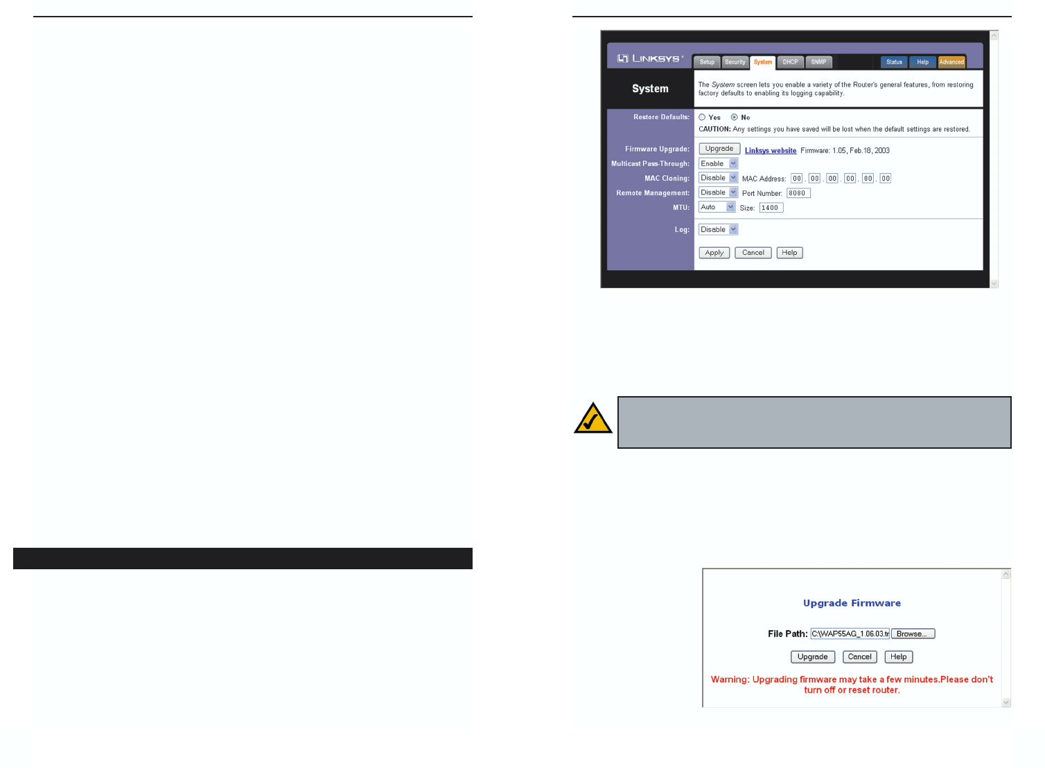
The System screen, shown in Figure 7-13, lets you control a variety of the
Router’s general features, from restoring factory defaults to enabling its remote
management capability.
Restore Factory Defaults Click the Yes button to reset all configuration set-
tings to their default values, and then click the Apply button. Any settings you
have saved will be lost when the default settings are restored. This feature is
disabled by default.
46
System
Firmware Upgrade New firmware versions are posted at www.linksys.com
and can be downloaded for free. If the Router already works well, there’s no
need to download a newer firmware version, unless that version has a new fea-
ture that you want to use. (To learn about any new firmware with new features,
visit www.linksys.com.)
To upgrade the Router’s firmware:
1. Download the firmware upgrade file from www.linksys.com, and extract
the file using a file archive utility such as WinZip.
2. Click the Upgrade button.
3. On the Upgrade
Firmware screen
(see Figure 7-14),
click the Browse
button to find the
firmware upgrade
file you extract-
ed.
Figure 7-14
Note: By upgrading the Router’s firmware, you may lose the Router’s
configuration settings, so make sure you write down the Router’s set-
tings before you upgrade its firmware.
Figure 7-13
Dual-Band Wireless A+G Broadband Router
49
Instant Wireless®Series
48
4. Double-click the firmware upgrade file you extracted.
5. Click the Upgrade button, and follow the on-screen instructions.
Multicast Pass-Through IP Multicasting occurs when a single data transmis-
sion is sent to multiple recipients at the same time. Using the Multicast Pass-
Through feature, the Router allows IP multicast packets to be forwarded to the
appropriate computers. Keep the default setting, Enable, to support the feature,
or select Disable to disable it.
MAC Cloning You can clone the MAC address of your PC’s network adapter
onto the Router.
A MAC address is a 12-digit code assigned to a unique piece of hardware for
identification. Some ISPs require that you register the MAC address of your
PC’s network adapter, which was connected to your cable or DSL modem dur-
ing installation. To avoid calling your ISP and changing the MAC address that
is registered with the ISP, follow these instructions:
1. Select Enable.
2. Enter your adapter’s MAC address in the MAC Address field.
3. To save your new settings, click the Apply button. To cancel your changes,
click the Cancel button. To get more information about the features, click
the Help button.
To disable MAC address cloning, keep the default setting, Disable.
If you do not know your adapter’s MAC address, follow these instructions:
1. Click the Start button, and select Run.
2. Enter command in the field provided, and press the OK button.
3. At the command prompt, enter ipconfig /all. Then press the Enter key.
4. Write down your adapter’s physical address; this is the adapter’s MAC
address.
Remote Management This feature allows you to manage your Router from a
remote location, via the Internet. To disable this feature, keep the default set-
ting, Disable. To enable this feature, select Enable, and use the specified port
(default is 8080) on your PC to remotely manage the Router. You must also
change the Router's default password to one of your own, if you haven’t
already. A unique password will increase security.
To remotely manage the Router, enter http://xxx.xxx.xxx.xxx:8080 (the x’s
represent the Router's Internet IP address, and 8080 represents the specified
port) in your web browser’s Address field. You will be asked for the Router’s
password. After successfully entering the password, you will be able to access
the Router’s web-based utility.
MTU MTU is the Maximum Transmission Unit. It specifies the largest pack-
et size permitted for Internet transmission. Keep the default setting, Auto, to
have the Router select the best MTU for your Internet connection. To specify a
MTU size, select Manual, and enter the value desired (default is 1400). You
should leave this value in the 1200 to 1500 range.
Log The Router can keep logs of all traffic for your Internet connection. To
disable the Log function, keep the default setting, Disable. To monitor traffic
between the network and the Internet, select Enable.
To save your changes on this page, click the Apply button. To cancel any
unsaved changes on this page, click the Cancel button. To get more information
about the features, click the Help button.
Note: If the Remote Management feature is enabled, anyone who
knows the Router’s Internet IP address and password will be able to
alter the Router’s settings.
Important: When you are upgrading the firmware, do NOT turn off
the Router, and do NOT press the Reset button.
Dual-Band Wireless A+G Broadband Router
51
Instant Wireless®Series
50
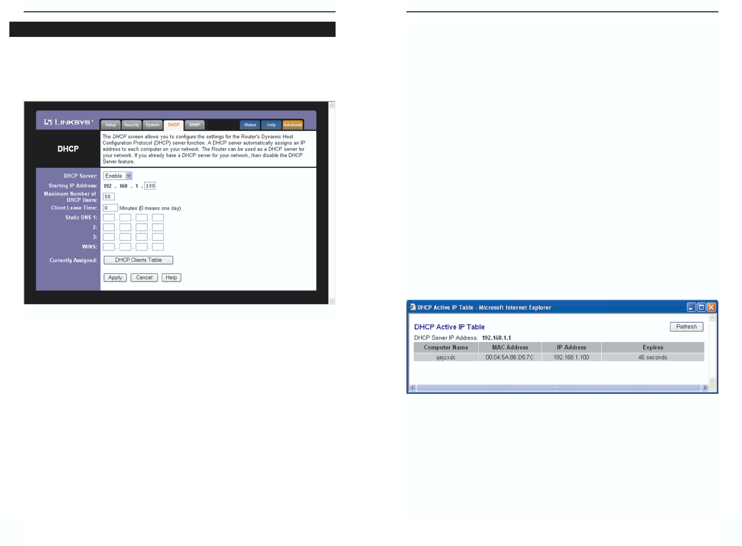
The DHCP screen, shown in Figure 7-15, allows you to configure the settings
for the Router’s Dynamic Host Configuration Protocol (DHCP) server function.
The Router can be used as a DHCP server for your network. A DHCP server
automatically assigns an IP address to each computer on your network.
If you choose to enable the Router’s DHCP server option, you must configure all
of your network PCs to connect to a DHCP server (the Router), and make sure
there is no other DHCP server on your network.
DHCP Server DHCP is enabled by factory default. If you already have a
DHCP server on your network, or you don’t want a DHCP server, then click the
Disable radio button (no other DHCP features will be available).
Starting IP Address Enter a value for the DHCP server to start with when
issuing IP addresses. Because the Router’s default IP address is 192.168.1.1,
the Starting IP Address must be 192.168.1.2 or greater, but smaller than
192.168.1.253. The default Starting IP Address is 192.168.1.100.
Maximum Number of DHCP Users (Optional) Enter the maximum number
of PCs that you want the DHCP server to assign IP addresses to. This number
cannot be greater than 253. The default is 50.
Figure 7-15
DHCP Client Lease Time The Client Lease Time is the amount of time a network
user will be allowed connection to the Router with their current dynamic IP
address. Enter the amount of time, in minutes, that the user will be “leased” this
dynamic IP address. After the time is up, the user will be automatically
assigned a new dynamic IP address. The default is 0minutes, which means one
day.
Static DNS 1-3 The Domain Name System (DNS) is how the Internet trans-
lates domain or website names into Internet addresses or URLs. Your ISP will
provide you with at least one DNS Server IP Address. If you wish to use anoth-
er, type that IP Address in one of these fields. You can type up to three DNS
Server IP Addresses here. The Router will use these for quicker access to func-
tioning DNS servers.
WINS The Windows Internet Naming Service (WINS) manages each PC’s
interaction with the Internet. If you use a WINS server, enter that server’s IP
Address here. Otherwise, leave this blank.
Currently Assigned: DHCP Clients Table Click the DHCP Clients Table
button to view the list of PCs that are given IP addresses by the Router (see
Figure 7-16). For each PC, the list shows the Client Hostname, IP Address,
MAC Address, and and the amount of DHCP client lease time left. Click the
Refresh button to display the most current information.
To save your changes on this page, click the Apply button. To cancel any
unsaved changes on this page, click the Cancel button. To get more information
about the features, click the Help button.
Figure 7-16
Instant Wireless®Series
52 53
Dual-Band Wireless A+G Broadband Router
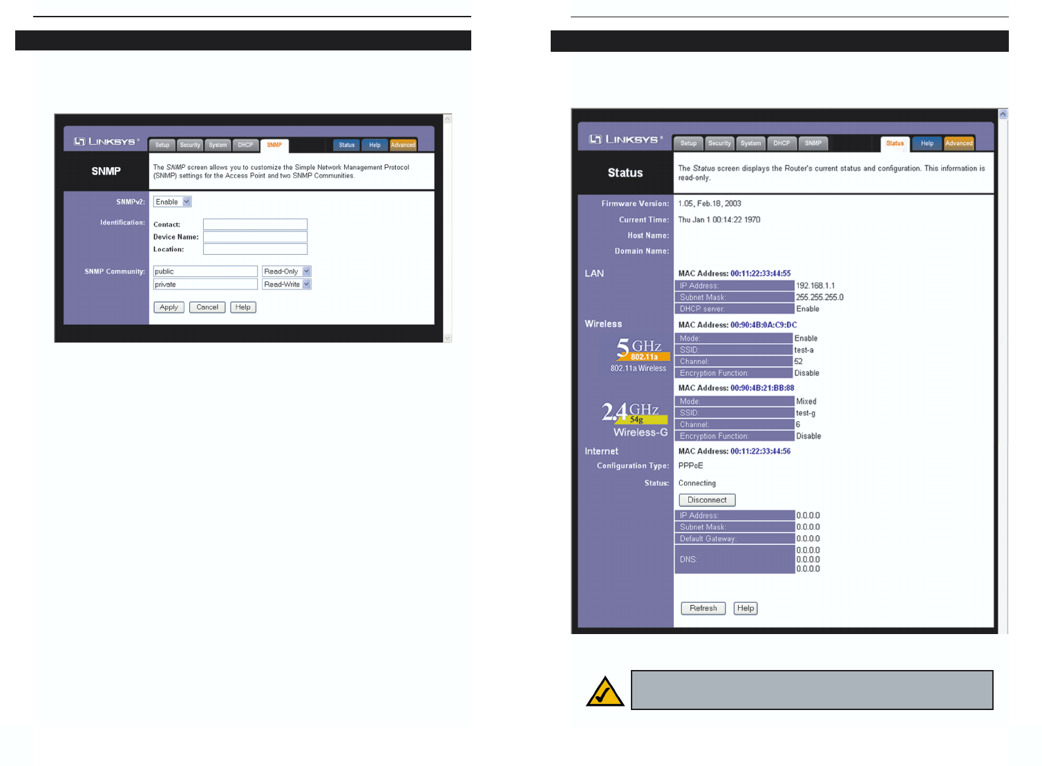
The Status screen, shown in Figure 7-18, displays the Router’s current status
and configuration. All information is read-only.
Status
Figure 7-18
Note: The information provided and buttons available may vary
depending on the Router’s settings.
The SNMP tab, shown in Figure 7-17, allows you to customize the Simple
Network Management Protocol (SNMP) settings. SNMP is a popular network
monitoring and management protocol.
The Identification settings let you designate the Contact, Device Name, and
Location information for the Router. The SNMP Community settings allow
names to be assigned to any SNMP communities that have been set up in the
network. You can define two different SNMP communities, with the default
names being Public and Private.
SNMPv2. To enable the SNMP support feature, select Enable.
Identification. In the Contact field, enter contact information for the Router.
In the Device Name field, enter the name of the Router. In the Location field,
specify the area or location where the Router resides.
SNMP Community. You may change the name from its default, Public. Enter
a new name in the Public field. Then configure the community's access as
either Read-Only or Read-Write.You may change the name from its default,
Private. Enter a new name in the Private field. Then configure the communi-
ty's access as either Read-Only or Read-Write.
When you’ve completed making any changes on this tab, click the Apply but-
ton to save those changes or Cancel to cancel your changes. For more infor-
mation on this tab, you can click the Help button.
Figure 7-17
SNMP