Compal Electronics TP00062AWD Digitizer I/O Device User Manual RF module manual
Compal Electronics Inc Digitizer I/O Device RF module manual
Contents
- 1. User manual regulatory
- 2. User manual
- 3. RF module manual
RF module manual

Wacom Digitizer
Wacom
Digitizer
Implementation Guide
Implementation
Guide
Component Business Division
Wacom Co., Ltd.
1 • 30.10.2007 • Wacom Confidential

Contents
1. Principle of Wacom EMR
2. General Specification
3. Structure
4. Digitizer Lineup
5. Display Lineup
6. Customizing Digitizer
7. System Designing (EM noise)
8. System Designing2 (metal parts)
9. System Calibration
10. Driver
2 • 30.10.2007 • Wacom Confidential
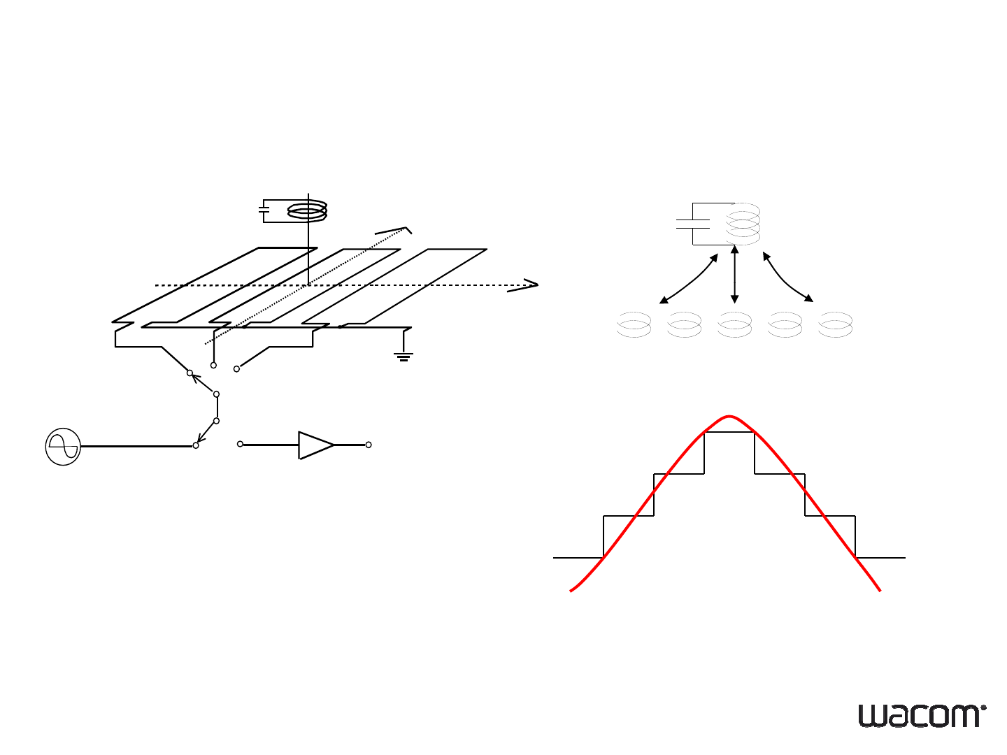
1. Principle of Wacom EMR
Receivin
g
and transmittin
g
coil in st
y
lus
Pen
Y axis
Xaxis
ggy
Antenna coil
Sensor Board
X
axis
Coil switching
transmit/receive
Receiver
V
High frequency
Receiver
source
Signal strength
3 • 30.10.2007 • Wacom Confidential

2. General Specification
WDiitiUit
Technology EMR (Electro-Magnetic Resonance)
W
acom
Di
g
iti
zer
U
n
it
Active Area 263.12 * 165.2 mm for SU5E-12W16AS-00X
Resolution 0.01mm (2540 ppi)
Coordinate Accuracy
±
0 4mm (see Note 1 and 2)
Coordinate
Accuracy
±
0
.
4mm
(see
Note
1
and
2)
Coordinate Deviation When Tilting Pen ±3mm (tilted ±50º from vertical) (see Note 3)
Detectable Pen tilt U
p
to 50°from vertical
p
Detectable Height 4 to 14mm above the Sensor Board (see Note 1)
Position Report Rate 133 pps
Pressure Resolution 256 levels @ full scale
Power Consumption 35mA (max.70mA) @133pps
Note 1: The digitizer sensor unit and pen only, at ordinary temperature.
Note 2: The pen held vertically at 7mm high from sensor board.
Nt 3Th hldi th t fth ti
4 • 30.10.2007 • Wacom Confidential
N
o
t
e
3
:
Th
e pen
h
e
ld
i
n
th
e cen
t
er o
f
th
e ac
ti
ve area.
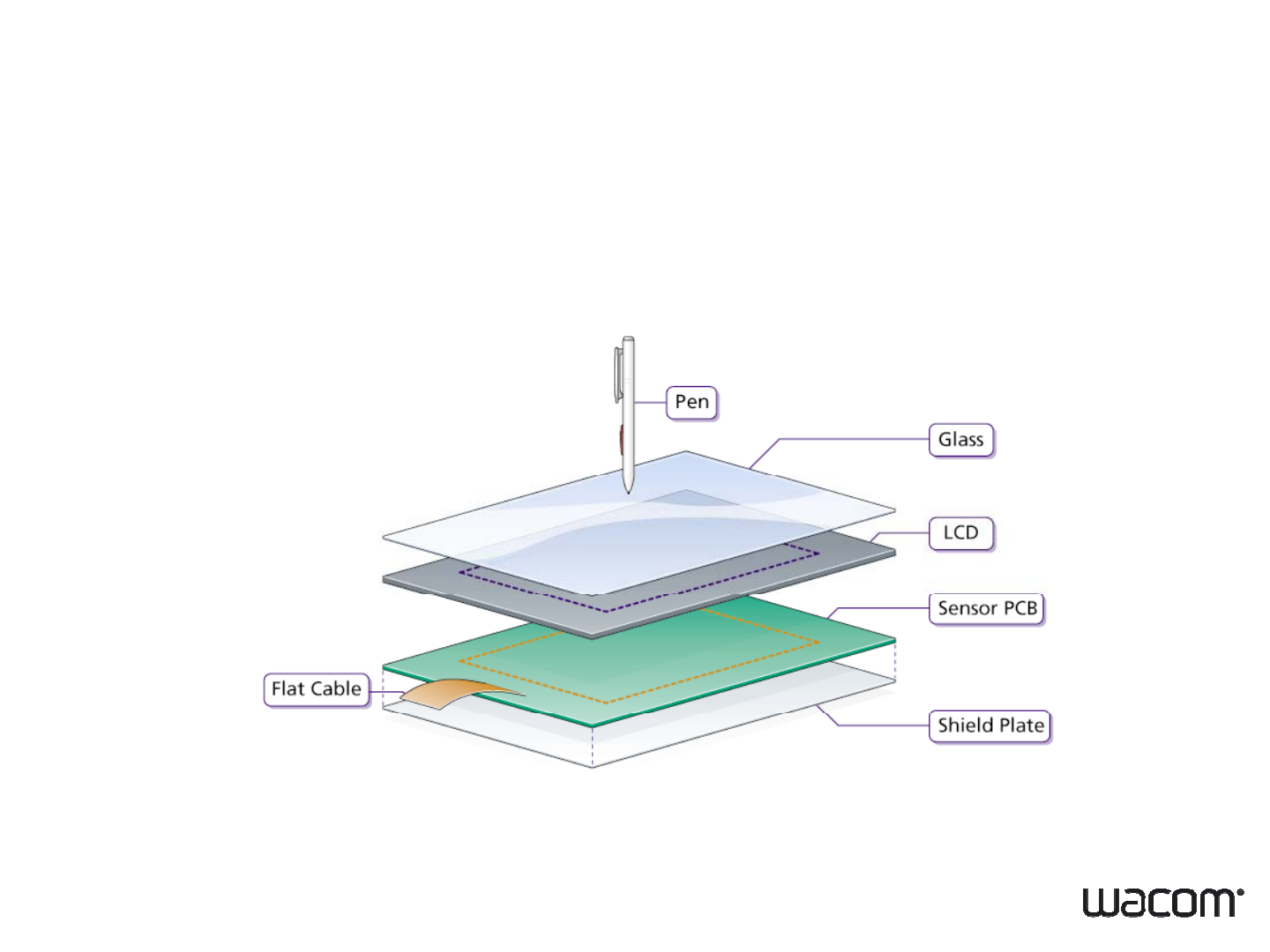
3-1. Structure
EMR digitizer be inserted under the LCD
5 • 30.10.2007 • Wacom Confidential
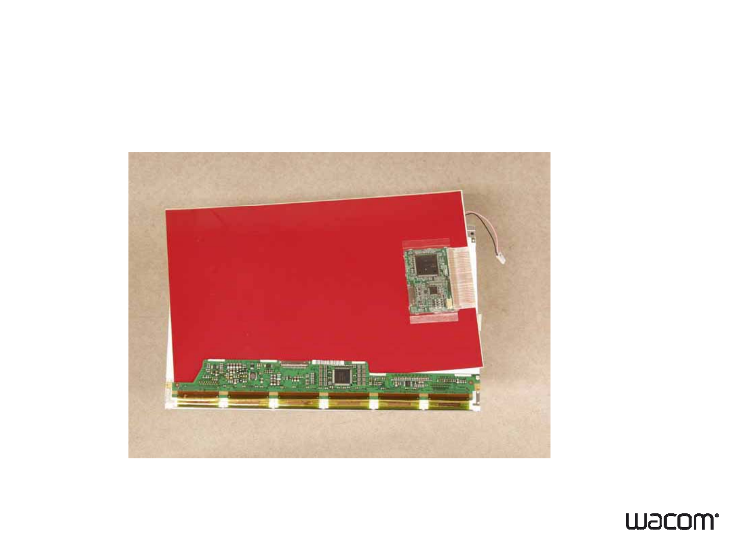
3-2. Structure
EMR digitizer be inserted under the LCD
6 • 30.10.2007 • Wacom Confidential
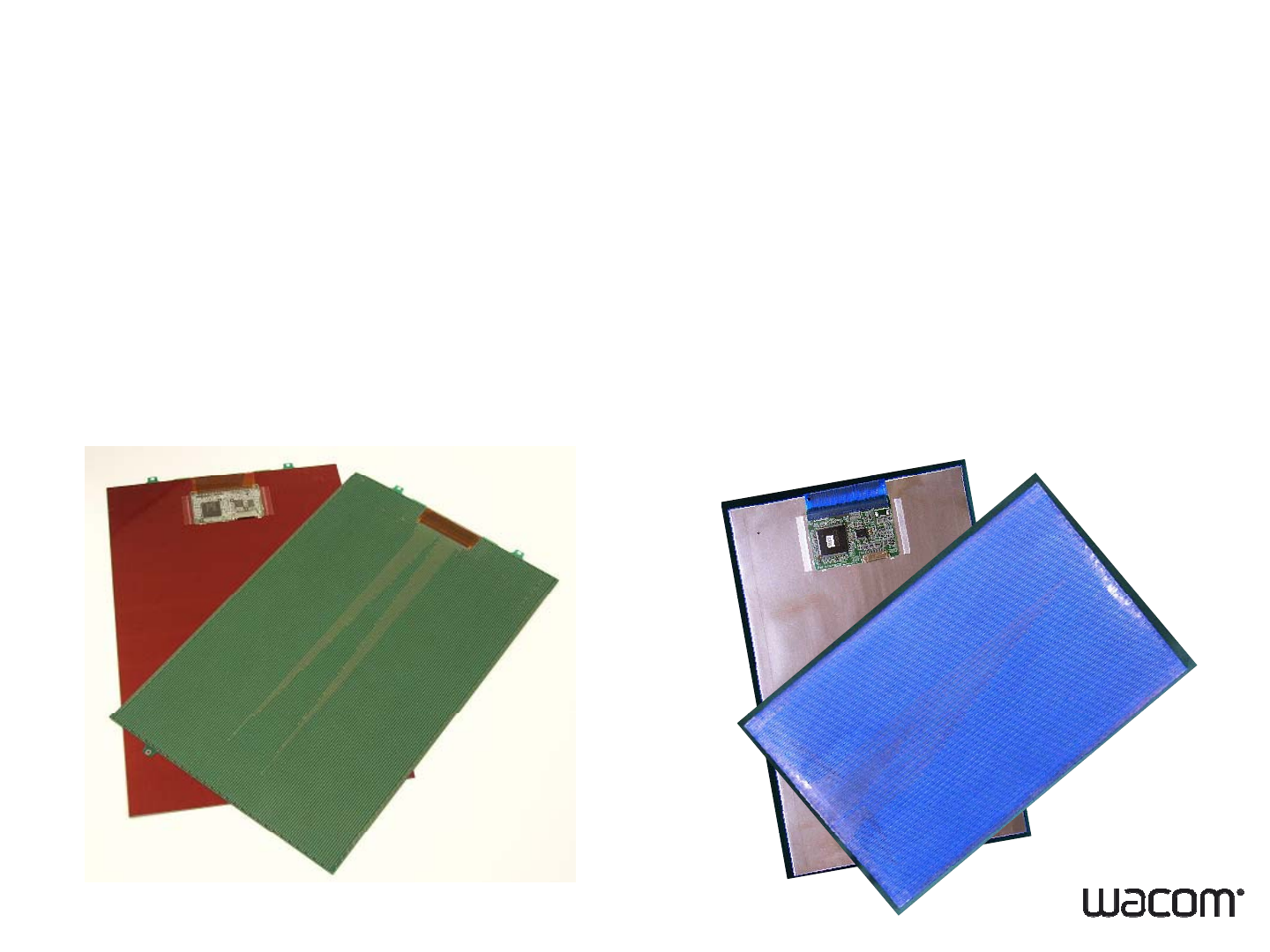
4-1. Digitizer Lineup
Sensor : G4 ・・・ glass epoxy sensor
G4.5 ・・・ glass epoxy sensor
G5 ・・・ PET film or FPC (Polyimide)
G4/G4.5 G5
7 • 30.10.2007 • Wacom Confidential
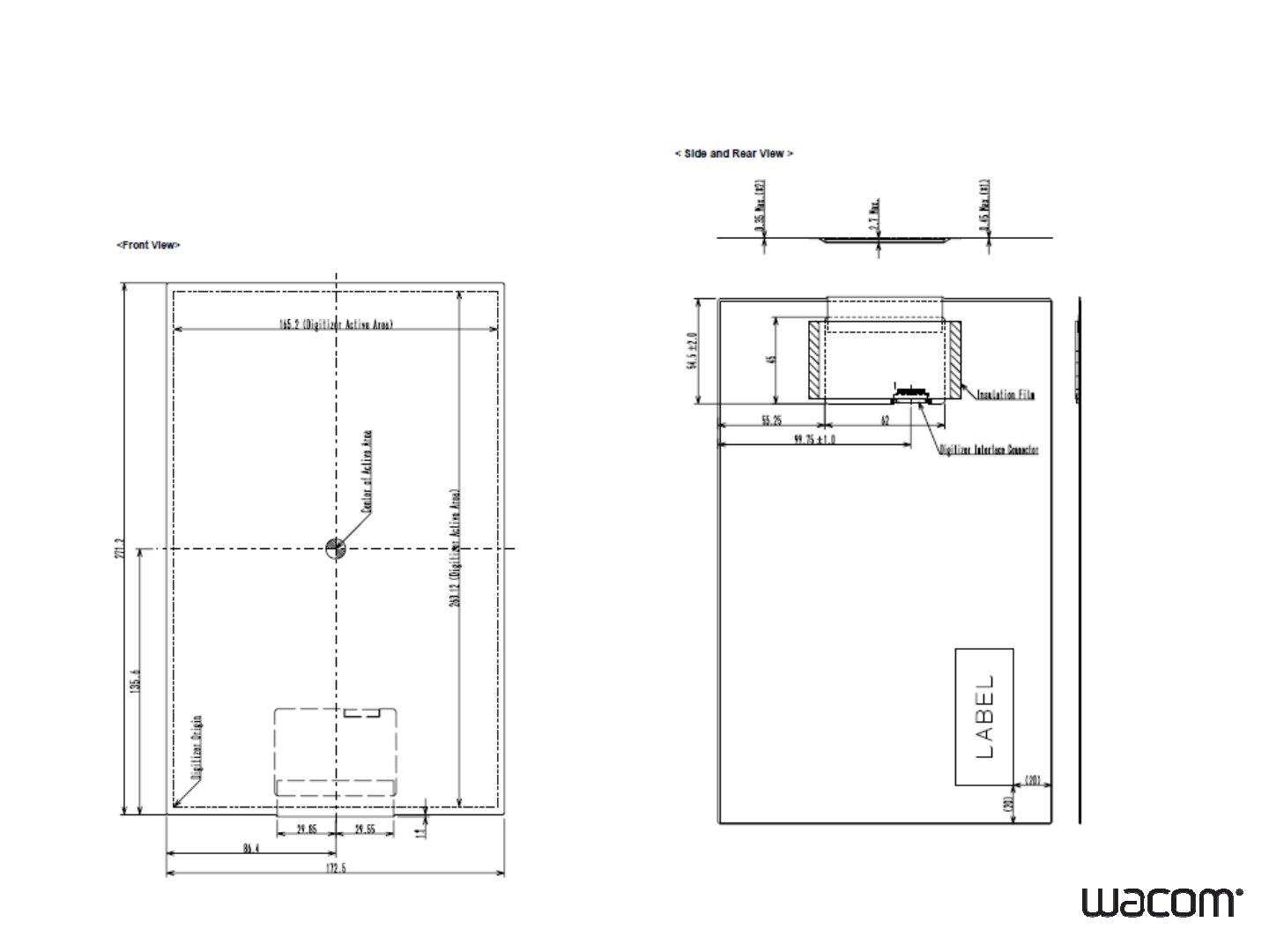
4-2. Digitizer Lineup
G5 sensor
8 • 30.10.2007 • Wacom Confidential
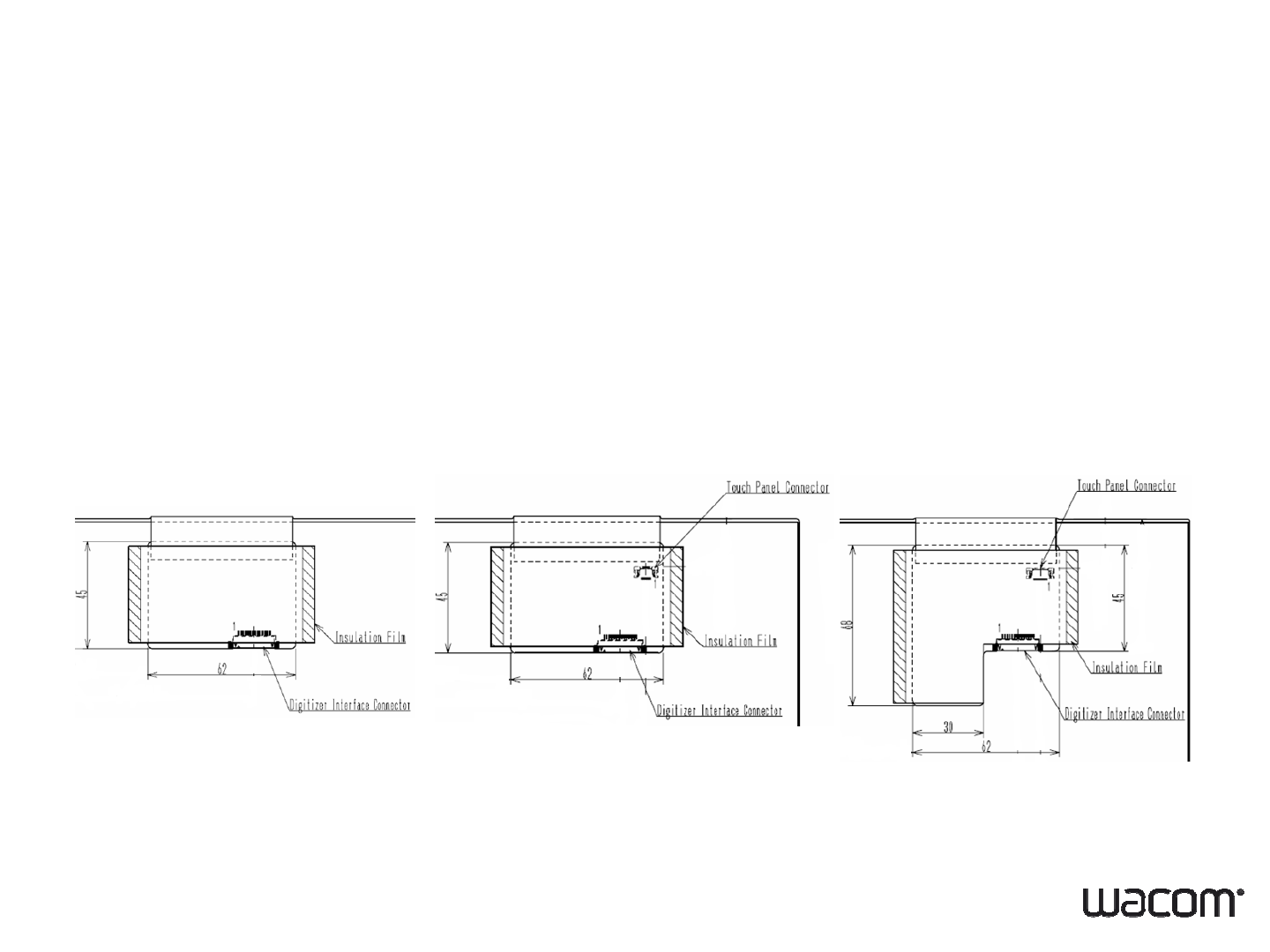
4-3. Digitizer Line up
Technology :
1. EMR onl
y
y
2. Resistive-DualTouch・・・ sensor + Resistive Touch screen interface
3. Capacitive-DualTouch・・・ sensor + Capacitive Touch screen interface
EMR only R-Dual C-Dual
9 • 30.10.2007 • Wacom Confidential
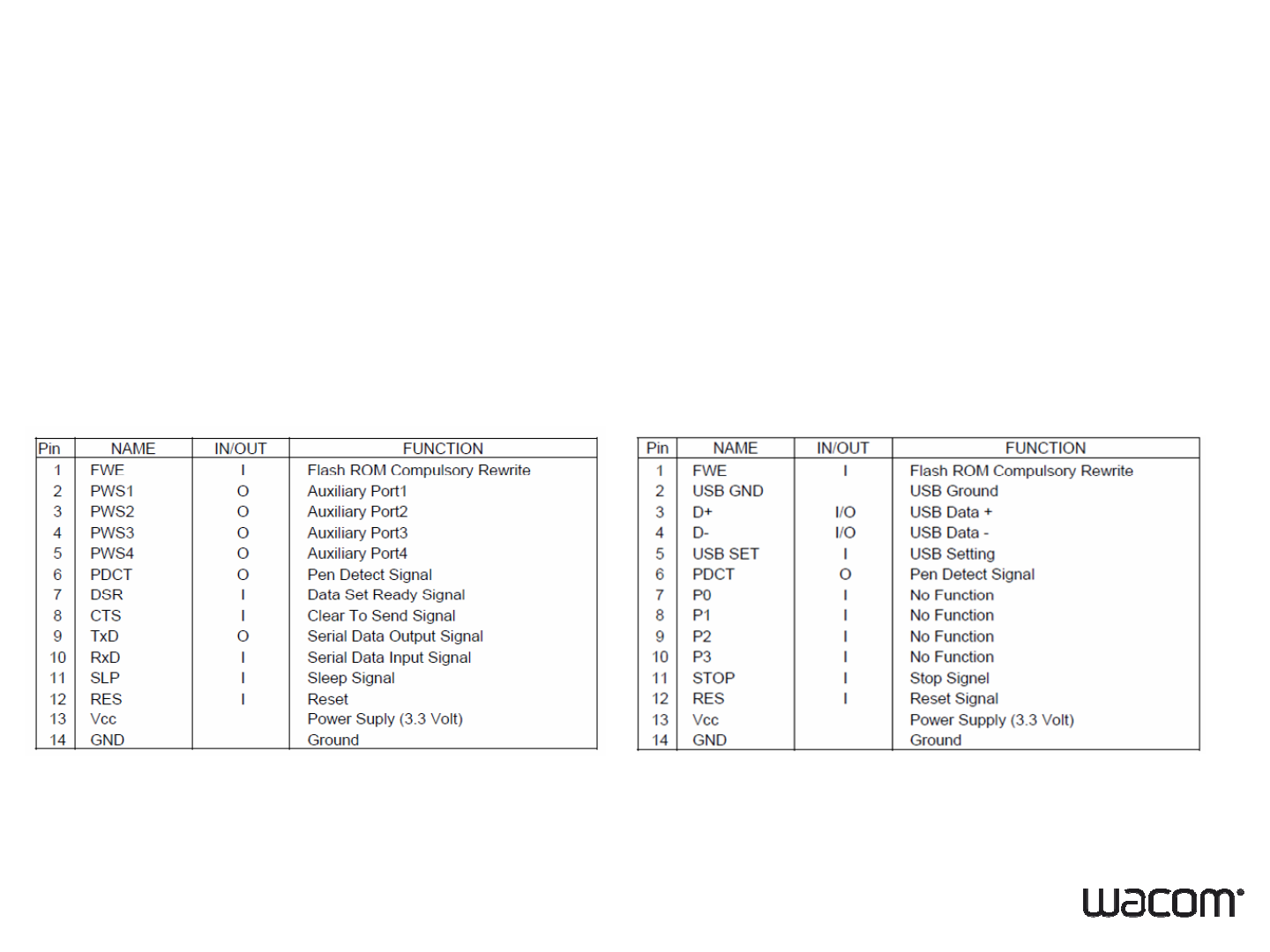
4-4. Digitizer Lineup
Interface : UART, USB
Si l i t (UART)
Si
gna
l
ass
i
gnmen
t
(UART)
Signal assignment (USB)
10 • 30.10.2007 • Wacom Confidential
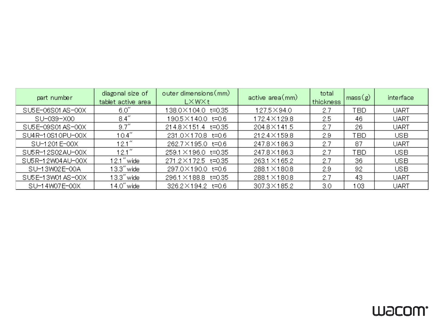
4-5. Digitizer Lineup
11 • 30.10.2007 • Wacom Confidential
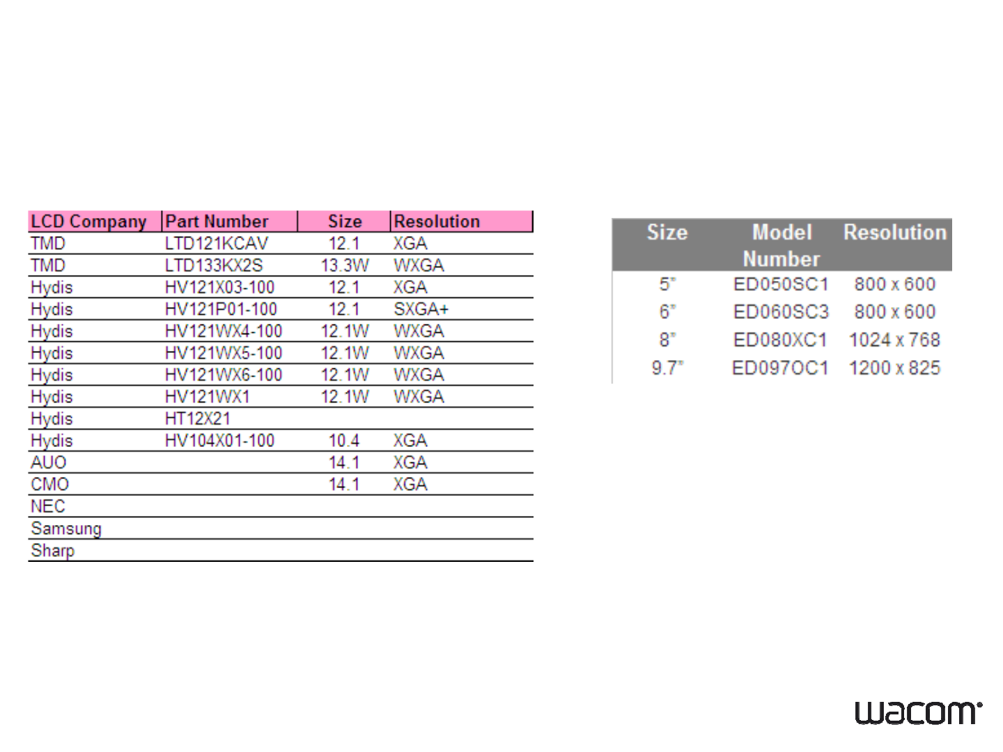
5. Display Lineup
LCD---Kangaroo type ・E-ink display
12 • 30.10.2007 • Wacom Confidential
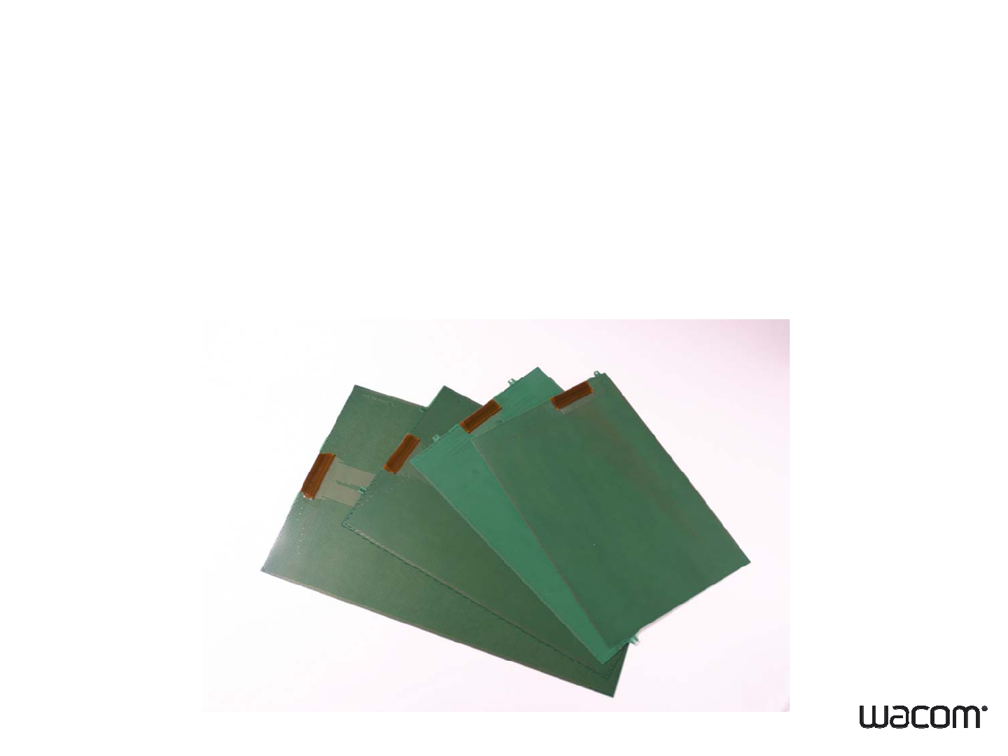
6-1. Customizing Digitizer
Condition for digitizer customization
1. Minimum Volume: 30K/
y
ea
r
y
2. There will be NRE and Tooling Cost
13 • 30.10.2007 • Wacom Confidential

6-2. Customizing Digitizer
Sensor Board Design
1. Must be square shape
rectangle square round heart
2. Must be flat
3
Non
acti e area m st be at least 4mm at each side
OK NG
3
.
Non
-
acti
v
e
area
m
u
st
be
at
least
4mm
at
each
side
tli
at least
4mm
ou
tli
ne
active area digitizer
14 • 30.10.2007 • Wacom Confidential
6-3. Customizing Digitizer
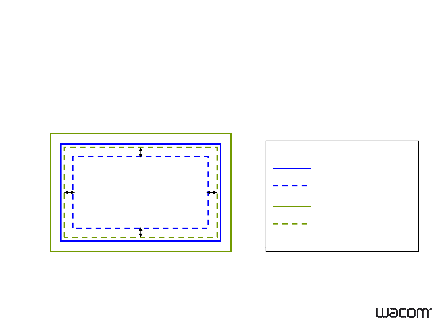
Sensor Board Design (continued)
4. Di
g
itizer active area needs at lease 1mm buffer from LCD active
g
area at each side
LCD outline
1mm
1mm
1mm
LCD
outline
LCD active area
digitizer outline
1mm
digitizer
outline
digitizer active area
15 • 30.10.2007 • Wacom Confidential

6-4. Customizing Digitizer
Baby Board Design
Onl
y
standard desi
g
n available.
yg
Interface connector
C t di iti DF19L
14P
1H (HIROSE) i l t
C
onnec
t
or on
di
g
iti
zer:
DF19L
-
14P
-
1H
(HIROSE)
or equ
i
va
l
en
t
Counterpart connector: DF19-14S-1S, DF19G-14S-1C (HIROSE) or
equivalent
16 • 30.10.2007 • Wacom Confidential

6-5. Customizing Digitizer
Dl tShdl
D
eve
l
opmen
t
S
c
h
e
d
u
l
e
No. Step Lead Time
1
Cfi t di i t
1
C
on
fi
rm cus
t
om
d
es
i
gn requ
i
remen
t
2Release of tentative shipping specification At the same time as ES sample shipment
3
ES sample shipment
8
10 weeks
3
ES
sample
shipment
*handmade sample with default firmware
8
-
10
weeks
4Customer confirmation of shipping specification
5System calibration 2 weeks
6Customer approval of ES sample
7
CS l hi t
8
10 k
7
CS
samp
l
e s
hi
pmen
t
*tooled sample with final calibrated firmware
8
-
10
wee
k
s
8Release of final shipping specification At the same time as CS sample shipment
8Customer approval of MP
(including shipping specification, FW and CS sample)
9MP shipment 8-10 weeks
17 • 30.10.2007 • Wacom Confidential
Note: Lead time stated here is only reference and may change depending on digitizer design. Please confirm the final
development schedule with Wacom sales.

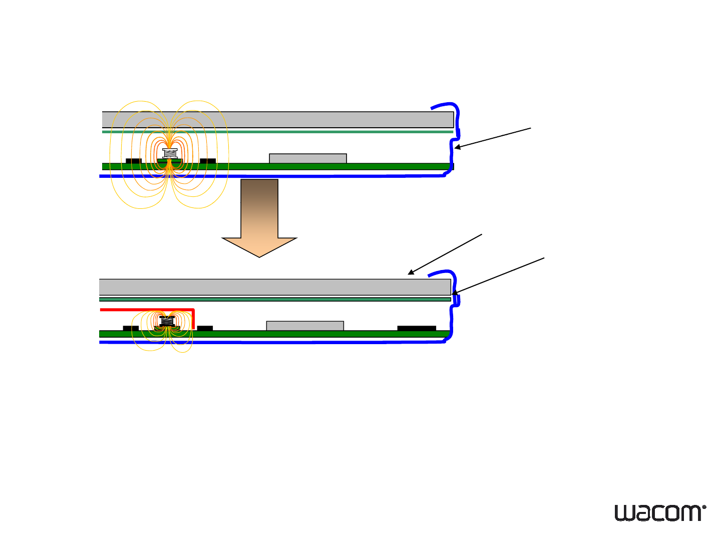
7-1. System Designing
Prevention of EM noise problem
Some transformers or coils in the po er nit generates EM noise
Some
transformers
or
coils
in
the
po
w
er
u
nit
generates
EM
noise
.
To
prevent
this
To
prevent
this
• Use transformers or coils that won’t allow magnetic flux leakage.
• Place them underneath the shield or in a distance as much as possible from the
sensor board.
• Position them so that EM noise flux did not across the senso
r
board.
EM noise source
•
Inverter
of
LCD
back
light
•
Inverter
of
LCD
back
light
• DC to DC converter in power circuit
18 • 30.10.2007 • Wacom Confidential
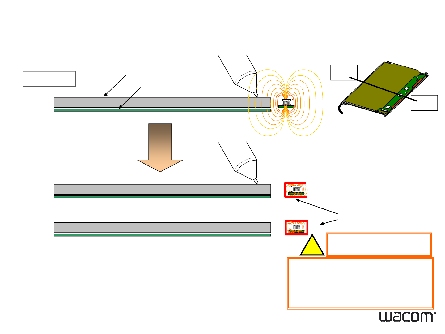
7-2. System Designing
B
View B-B’
LCD
EM Noise Countermeasure
B’
Digitizer
Inverter
Shield
or
IMPORTANT
!
Digitizer is sensitive to Electromagnetic Noise.
Inverter is one of the strongest EM source.
Shielding the inverter with shield plate*1, would improve
an affection of the EM noise from the Inverter
As far as you can,please
SEPARATE the Digitizer Unit
!
19 • 30.10.2007 • Wacom Confidential
an
affection
of
the
EM
noise
from
the
Inverter
.from the Inverter
7-3. System Designing
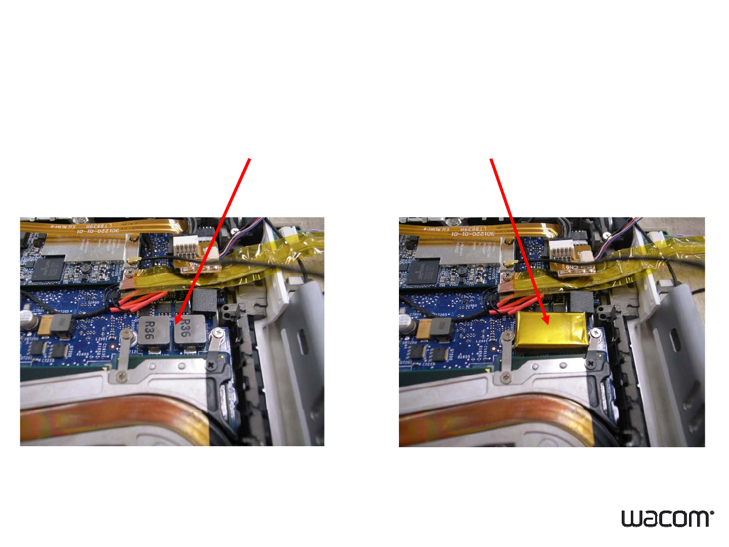
PC Case
EM Noise Countermeasure2
LCD
Digitizer
COIL
Like DC-DC Converter
In case of PC in one body, motherboard is located right beneath the
Di
g
itizer unit. Coils in the
p
ower unit
g
enerates the EM noise and it will
gpg
cause of inaccuracy of the Digitizer.
Shield the COIL with shield plate*1 for better Digitizer quality.
20 • 30.10.2007 • Wacom Confidential
7-4. System Designing
Example of Noise Shield1
Noise Source Shielded
21 • 30.10.2007 • Wacom Confidential
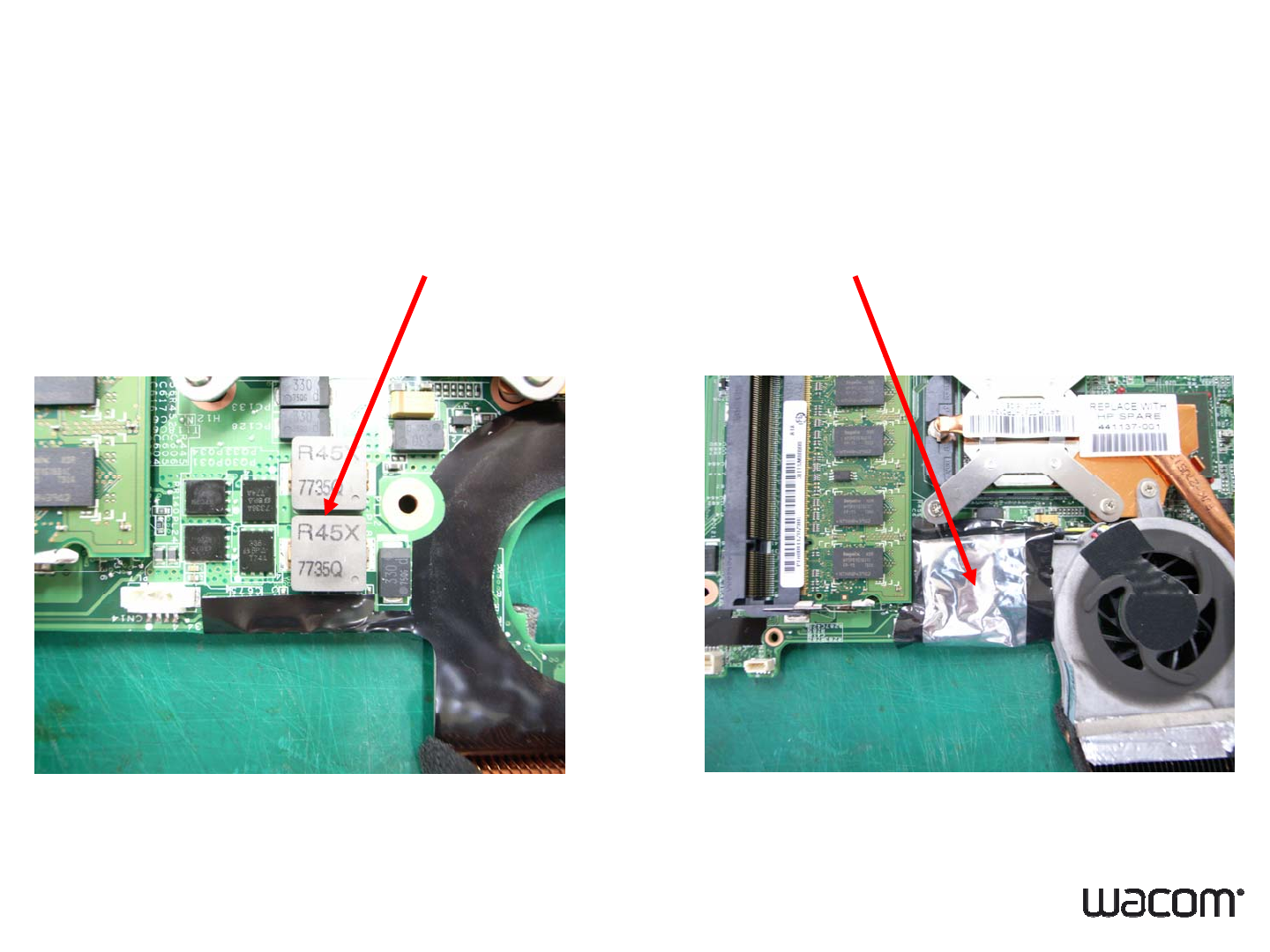
7-5. System Designing
Example of Noise Shield2
Noise Source Shielded
22 • 30.10.2007 • Wacom Confidential

8-1. System Designing2
Reduction of metal influence
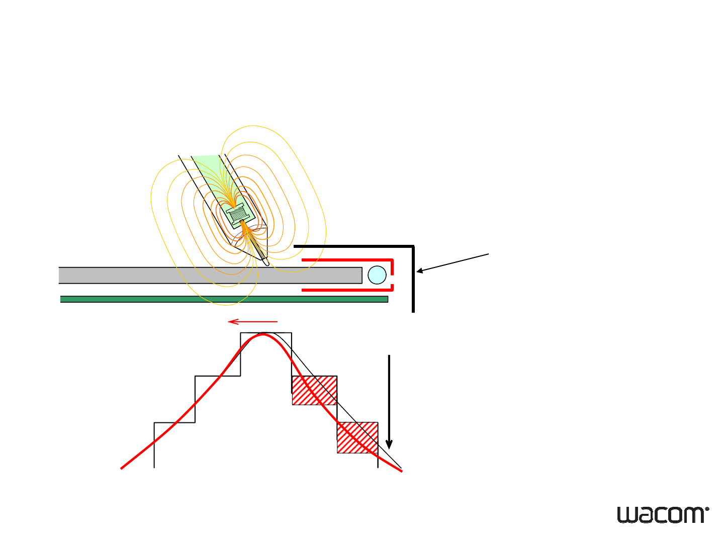
Some metal structure reduces digitizer signal which causes coordinate error.
To
prevent
this
To
prevent
this
• Do not use metal for upper case.
• Contact Wacom to make Error calibrated firmware data.
Metal influence source
• LCD metal bezel and lamp cover
• Upper case ( if it is made of metal )
23 • 30.10.2007 • Wacom Confidential
8-2. System Designing2
Minimize Metal influence
LCD Upper Bezel
Upper case
LCD Lamp cover
EM signal decrease
EM
signal
decrease
24 • 30.10.2007 • Wacom Confidential
Metal on the digitizer will disturb the EM signal from the pen.
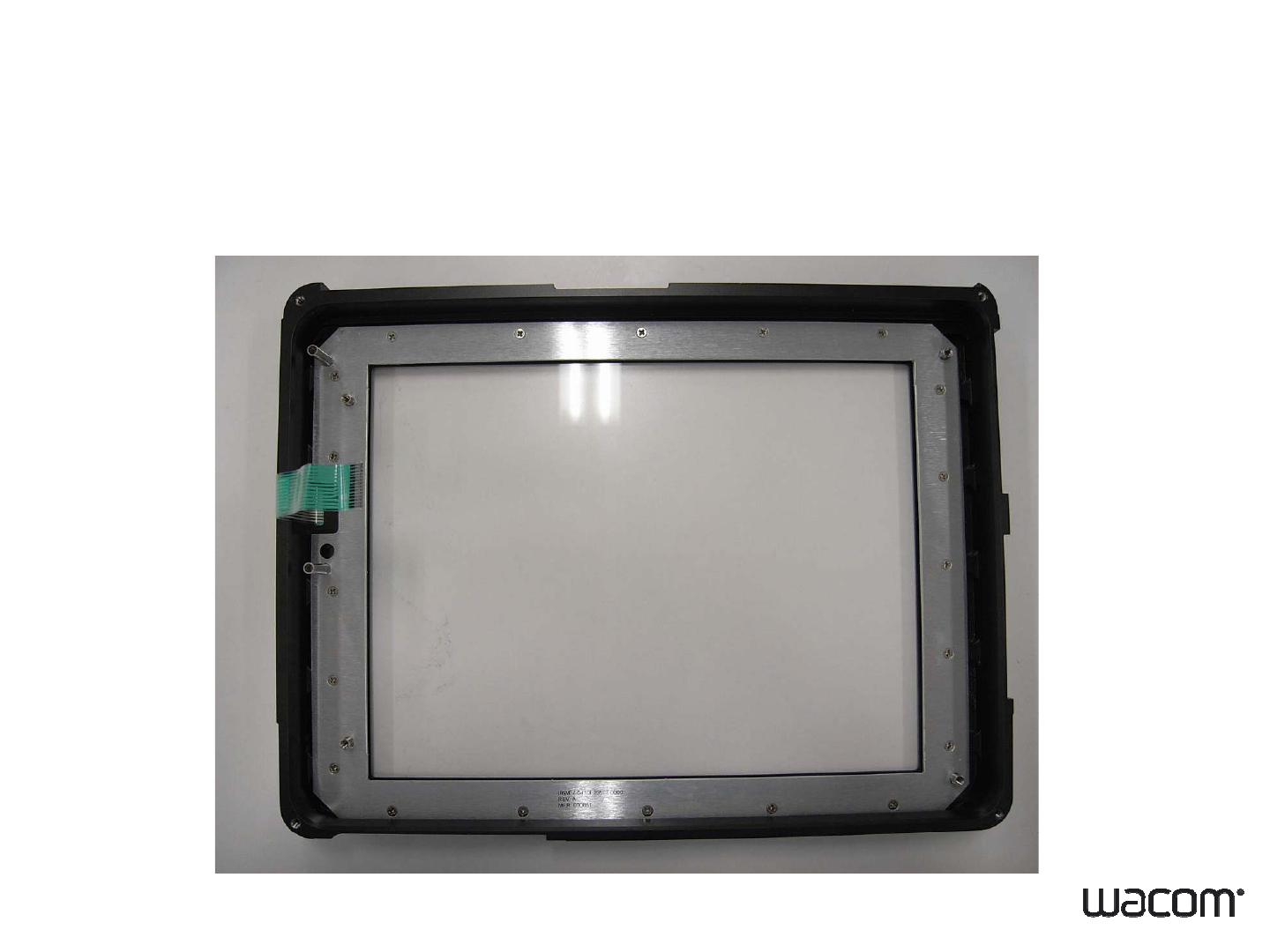
8-3. System Designing2
Full Metal Upper Case
Bad Example of Metal Parts1
25 • 30.10.2007 • Wacom Confidential
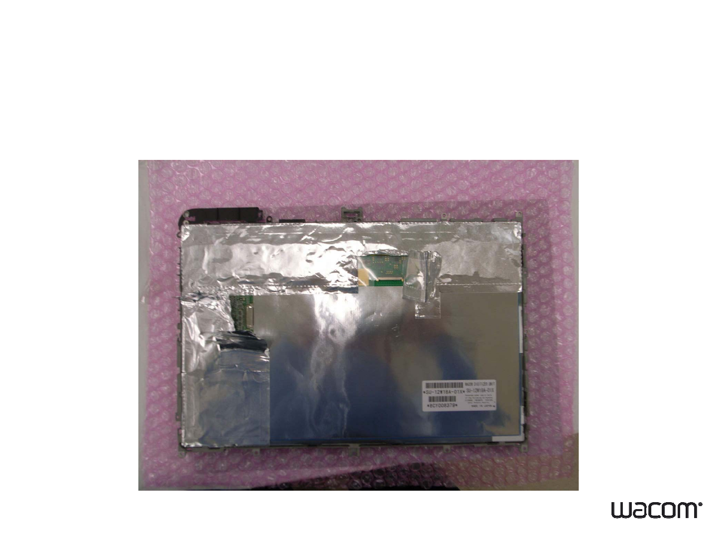
8-4. System Designing2
Wrapped by Metal Sheet
Bad Example of Metal Parts2
26 • 30.10.2007 • Wacom Confidential
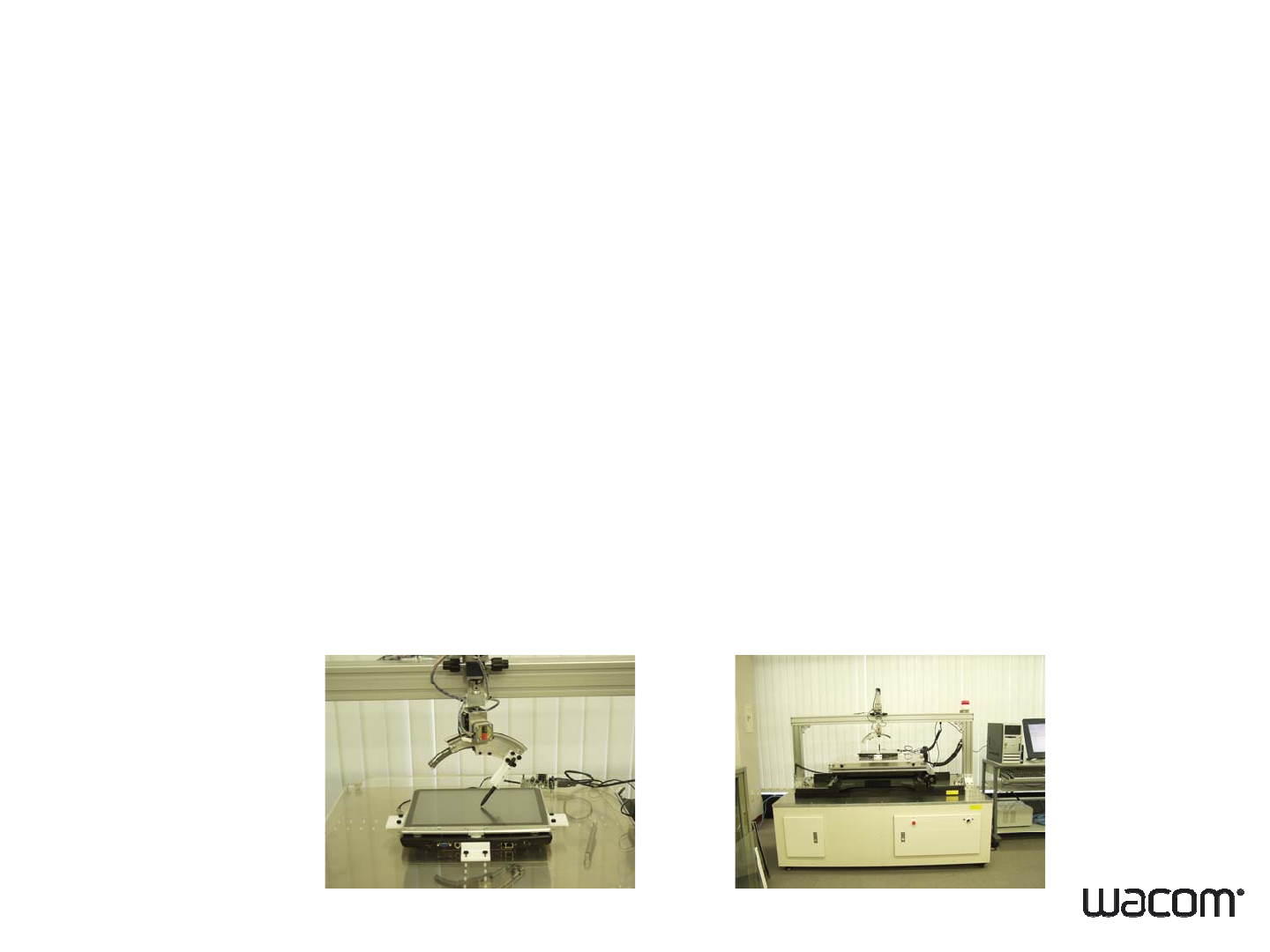
9-1. System Calibration
Wacom will do following evaluation in order to prevent
adverse affect from EM noise and metal parts
1. EM noise environment
2. Coordinate stability
3
Coordinate accuracy
3
.
Coordinate
accuracy
Wacom will provide FW data and evaluation report.
Calibration work will take approximately 1-2 weeks.
C lib i k h i US$1 200 lib i
C
a
lib
rat
i
on wor
k
c
h
arge
i
s
US$1
,
200
per ca
lib
rat
i
on.
27 • 30.10.2007 • Wacom Confidential
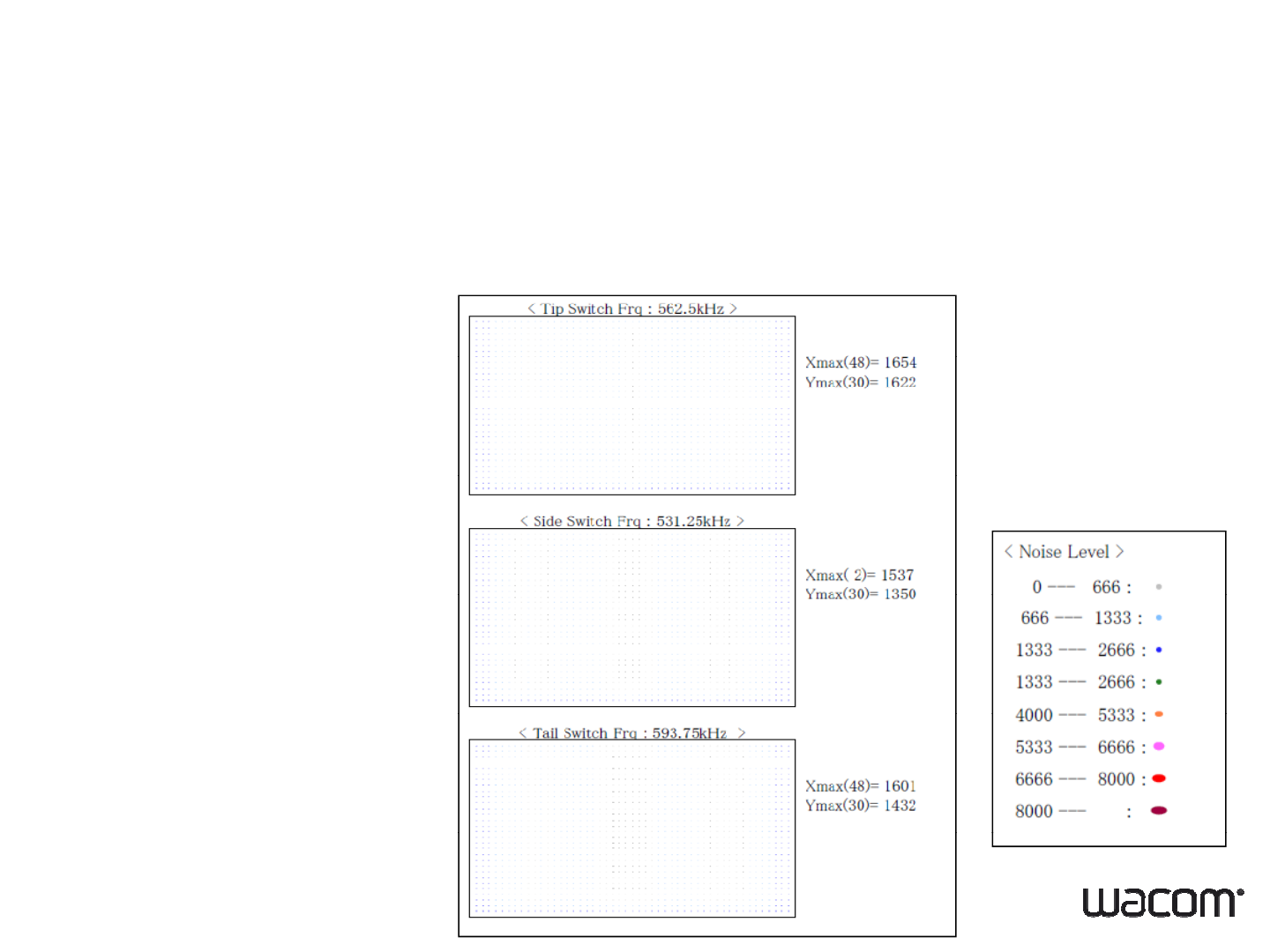
9-2. System Calibration
EM noise environment
•EM noise which mimic pen signal can cause digitizer malfunction.
•
Wacom will search the EM noise and measure the level
•
Wacom
will
search
the
EM
noise
and
measure
the
level
.
28 • 30.10.2007 • Wacom Confidential
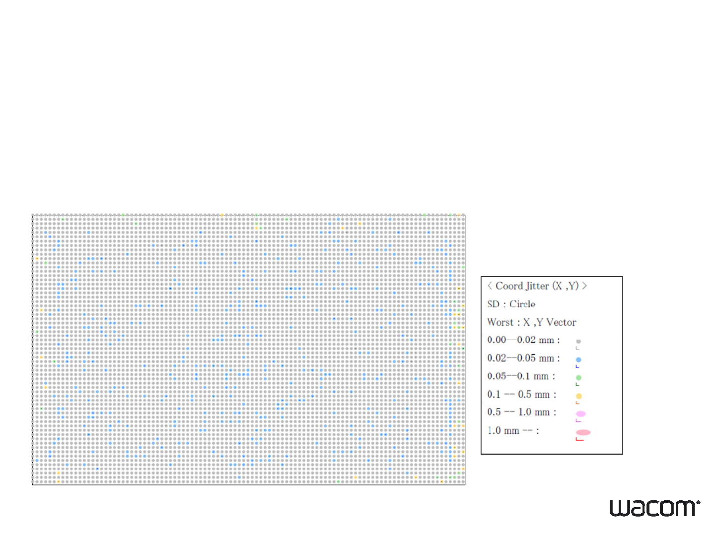
9-3. System Calibration
Coordinate stability
EM noise can cause vibration of coordinate detected by digitizer (jitter).
Wacom quantifies the level of jitter by take 100 coordinate data at each
spot and calculating standard deviation and max deviation from mean
location.
29 • 30.10.2007 • Wacom Confidential
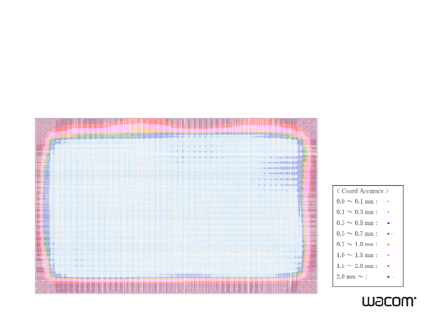
9-4. System Calibration
C di t b f lib ti
C
oor
di
na
t
e accuracy
b
e
f
ore ca
lib
ra
ti
on
Metal parts or EM noise will disturb digitizer signal and can cause the
deterioration of digitizer accuracy.
Digitizer signal can be compensated by calibration up to certain level.
Wacom measures the accuracy before and after calibration.
30 • 30.10.2007 • Wacom Confidential

9-5. System Calibration
Coordinate accuracy after calibration
31 • 30.10.2007 • Wacom Confidential

9-6. System Calibration
Before sending calibration machine, please check
below items.
1
Final design
1
.
Final
design
2. Tooled product
3
.All
c
ri
te
ri
a
f
o
r
syste
m
des
i
g
n i
s
f
o
ll
o
w
ed
3
c te a o syste des g s o o ed
4. All accessories (eg. AC adaptor) are enclosed
5. Valid OS is installed
6. Wacom stylus (which pen to use with)
7. Assembly drawing to show LCD and digitizer position
Note:
Calibration is required for each design. Any material or design
changes will need another calibration.
When several LCDs are applied for one model FW needs to be
32 • 30.10.2007 • Wacom Confidential
When
several
LCDs
are
applied
for
one
model
,
FW
needs
to
be
created for each LCD.

10. Driver
Device Driver
Windows Vista, Windows XP, Windows 2000, Windows CE ,
Symbian
Symbian
Note:
Note:
for dual touch, standard interface is USB
33 • 30.10.2007 • Wacom Confidential