Contents
- 1. AR-5389_user manual-1
- 2. AR-5389_user manual-2
- 3. AR-5389_user manual-3
- 4. AR-5389_user manual-4
AR-5389_user manual-1

74ok
AR-5389
ADSL2+ WLAN Router
User Manual
Version A1.0, May 10, 2013
261056-063

1
Preface
This manual provides information related to the installation and operation of this
device. The individual reading this manual is presumed to have a basic
understanding of telecommunications terminology and concepts.
If you find the product to be inoperable or malfunctioning, please contact technical
support for immediate service by email at INT-support@comtrend.com
For product update, new product release, manual revision, or software upgrades,
please visit our website at http://www.comtrend.com
Important Safety Instructions
With reference to unpacking, installation, use, and maintenance of your electronic
device, the following basic guidelines are recommended:
Do not use or install this product near water, to avoid fire or shock hazard. For
example, near a bathtub, kitchen sink or laundry tub, or near a swimming pool.
Also, do not expose the equipment to rain or damp areas (e.g. a wet basement).
Do not connect the power supply cord on elevated surfaces. Allow it to lie freely.
There should be no obstructions in its path and no heavy items should be placed
on the cord. In addition, do not walk on, step on, or mistreat the cord.
Use only the power cord and adapter that are shipped with this device.
To safeguard the equipment against overheating, make sure that all openings in
the unit that offer exposure to air are not blocked.
Avoid using a telephone (other than a cordless type) during an electrical storm.
There may be a remote risk of electric shock from lightening. Also, do not use
the telephone to report a gas leak in the vicinity of the leak.
Never install telephone wiring during stormy weather conditions.
CAUTION:
To reduce the risk of fire, use only No. 26 AWG or larger
telecommunication line cord.
Always disconnect all telephone lines from the wall outlet before servicing
or disassembling this equipment.
WARNING
Disconnect the power line from the device before servicing.
Power supply specifications are clearly stated in Appendix B -
Specifications.

2
FCC Compliance
This equipment has been tested and found to comply with the limits for a Class B
Digital Device, pursuant to part 15 of the FCC Rules. These limits are designed to
provide reasonable protection against harmful interference in a residential
installation. This equipment generates, uses and can radiate radio frequency energy
and, if not installed and used in accordance with the instruction, may cause harmful
interference to radio communication. However, there is no grantee that interference
will not occur in a particular installation. If this equipment does cause harmful
interference to radio or television reception, which can be determined by turning the
equipment off and on, the user is encouraged to try to correct the interference by
one or more of the following measures:
Reorient or relocate the receiving antenna
Increase the separation between the equipment and receiver
Connect the equipment into an outlet on a circuit different from that to which
the receiver is connected
Consult the dealer or an experienced radio/TV technician for help.
The changes or modifications not expressly approved by the party responsible for
compliance could void the user's authority to operate the equipment.
To comply with the FCC RF exposure compliance requirements, this device and its
antenna must not be co-located or operating to conjunction with any other antenna
or transmitter.
This equipment should be installed and operated with minimum distance 20cm
between the radiator & your body.
Copyright
Copyright© 2013 Comtrend Corporation. All rights reserved. The information
contained herein is proprietary to Comtrend Corporation. No part of this document
may be translated, transcribed, reproduced, in any form, or by any means without
the prior written consent of Comtrend Corporation.
This program is free software: you can redistribute it and/or modify it under the
terms of the GNU General Public License as published by the Free Software
Foundation, either version 3 of the License, or (at your option) any later version.
This program is distributed in the hope that it will be useful, but WITHOUT ANY
WARRANTY; without even the implied warranty of MERCHANTABILITY or FITNESS
FOR A PARTICULAR PURPOSE. See the GNU General Public License for more
details.
You should have received a copy of the GNU General Public License
along with this program. If not, see http://www.gnu.org/licenses/
NOTE: This document is subject to change without notice.

3
Protect Our Environment
This symbol indicates that when the equipment has reached the end of
its useful life, it must be taken to a recycling centre and processed
separate from domestic waste.
The cardboard box, the plastic contained in the packaging, and the parts that make
up this router can be recycled in accordance with regionally established regulations.
Never dispose of this electronic equipment along with your household waste; you
may be subject to penalties or sanctions under the law. Instead, please be
responsible and ask for disposal instructions from your local government.
4
Table of Contents
CHAPTER 1 INTRODUCTION...................................................................................................... 6
CHAPTER 2 INSTALLATION........................................................................................................ 7
2.1 HARDWARE SETUP .....................................................................................................................7
2.2 FRONT PANEL ............................................................................................................................9
CHAPTER 3 WEB USER INTERFACE ....................................................................................... 11
3.1 DEFAULT SETTINGS .................................................................................................................. 11
3.2 IP CONFIGURATION .................................................................................................................. 11
3.3 LOGIN PROCEDURE .................................................................................................................. 14
CHAPTER 4 DEVICE INFORMATION....................................................................................... 16
4.1 WAN....................................................................................................................................... 17
4.2 STATISTICS .............................................................................................................................. 18
4.2.1 LAN Statistics ............................................................................................................ 18
4.2.2 WAN Service Statistics ............................................................................................... 19
4.2.3 xTM Statistics ............................................................................................................ 20
4.2.4 xDSL Statistics........................................................................................................... 21
4.3 ROUTE..................................................................................................................................... 25
4.4 ARP........................................................................................................................................ 26
4.5 DHCP ..................................................................................................................................... 27
4.5.1 DHCPv4........................................................................................................................... 27
4.5.2 DHCPv6........................................................................................................................... 28
4.6 NAT SESSION .......................................................................................................................... 29
4.7 IGMP PROXY .......................................................................................................................... 30
4.8 IPV6........................................................................................................................................ 31
4.8.1 IPv6 Info .......................................................................................................................... 31
4.8.2 IPv6 Neighbor.................................................................................................................. 32
4.8.3 IPv6 Route ....................................................................................................................... 33
CHAPTER 5 ADVANCED SETUP................................................................................................ 34
5.1 LAYER 2 INTERFACE................................................................................................................. 34
5.1.1 ATM Interface............................................................................................................ 34
5.1.2 PTM Interface............................................................................................................ 34
5.1.3 ETH Interface ............................................................................................................ 35
5.2 WAN SERVICE ......................................................................................................................... 36
5.3 LAN ....................................................................................................................................... 37
5.3.1 LAN IPv6 Autoconfig........................................................................................................ 40
5.3.2 Static IP Neighbor............................................................................................................ 43
5.4 AUTO-DETECTION ................................................................................................................... 44
5.5 NAT........................................................................................................................................ 48
5.5.1 Virtual Servers........................................................................................................... 48
5.5.2 Port Triggering.......................................................................................................... 50
5.5.3 DMZ Host.................................................................................................................. 52
5.5.4 IP Address Map ......................................................................................................... 53
5.5.5 IPSEC ALG ............................................................................................................... 55
5.5.6 SIP ALG .................................................................................................................... 56
5.6 SECURITY ................................................................................................................................ 57
5.6.1 IP Filtering................................................................................................................ 57
5.6.2 MAC Filtering ........................................................................................................... 60
5.7 PARENTAL CONTROL ................................................................................................................ 62
5.7.1 Time Restriction......................................................................................................... 62
5.7.2 URL Filter ................................................................................................................. 63
5.8 QUALITY OF SERVICE (QOS)..................................................................................................... 65
5.8.1 Queue Management Configuration............................................................................. 65
5.8.2 Queue Configuration ................................................................................................. 66
5.8.3 QoS Classification ..................................................................................................... 68
5
5.9 ROUTING ................................................................................................................................. 71
5.9.1 Default Gateway ........................................................................................................ 71
5.9.2 Static Route ............................................................................................................... 72
5.9.3 Policy Routing ........................................................................................................... 73
5.9.4 RIP............................................................................................................................ 74
5.10 DNS...................................................................................................................................... 75
5.10.1 DNS Server................................................................................................................ 75
5.10.2 Dynamic DNS............................................................................................................ 76
5.10.3 DNS Entries............................................................................................................... 78
5.11 DSL ...................................................................................................................................... 79
5.12 UPNP .................................................................................................................................... 81
5.13 DNS PROXY/RELAY............................................................................................................... 82
5.14 INTERFACE GROUPING............................................................................................................ 83
5.15 IP TUNNEL............................................................................................................................. 86
5.15.1 IPv6inIPv4 ..................................................................................................................... 86
5.15.2 IPv4inIPv6 ..................................................................................................................... 88
5.16 IPSEC .................................................................................................................................... 90
5.17 CERTIFICATE .......................................................................................................................... 94
5.17.1 Local ......................................................................................................................... 94
5.17.2 Trusted CA................................................................................................................. 97
5.18 MULTICAST ........................................................................................................................... 99
CHAPTER 6 WIRELESS ............................................................................................................ 100
6.1 SECURITY .............................................................................................................................. 100
6.1.1 WPS ............................................................................................................................... 102
6.2 MAC FILTER ......................................................................................................................... 107
6.3 WIRELESS BRIDGE ................................................................................................................. 108
6.4 ADVANCED ............................................................................................................................ 109
6.5 SITE SURVEY ......................................................................................................................... 112
6.6 STATION INFO ........................................................................................................................ 113
6.7 WIFI BUTTON ........................................................................................................................ 114
CHAPTER 7 DIAGNOSTICS...................................................................................................... 115
7.1 DIAGNOSTICS – INDIVIDUAL TESTS......................................................................................... 115
7.3 UPTIME STATUS..................................................................................................................... 117
CHAPTER 8 MANAGEMENT.................................................................................................... 118
8.1 SETTINGS .............................................................................................................................. 118
8.1.1 Backup Settings ....................................................................................................... 118
8.1.2 Update Settings........................................................................................................ 118
8.1.3 Restore Default........................................................................................................ 119
8.2 SYSTEM LOG ......................................................................................................................... 120
8.3 SNMP AGENT ....................................................................................................................... 122
8.4 TR-069 CLIENT ..................................................................................................................... 123
8.5 INTERNET TIME...................................................................................................................... 125
8.6 ACCESS CONTROL.................................................................................................................. 126
8.6.1 Accounts/Passwords................................................................................................. 126
8.6.2 Service Access ............................................................................................................. 128
8.6.3 IP Address................................................................................................................... 129
8.7 UPDATE SOFTWARE ................................................................................................................ 131
8.8 REBOOT................................................................................................................................. 132
APPENDIX A - FIREWALL ........................................................................................................ 133
APPENDIX B - SPECIFICATIONS ............................................................................................ 135
APPENDIX C - SSH CLIENT ..................................................................................................... 138
APPENDIX D - WPS OPERATION ............................................................................................ 139
APPENDIX E - CONNECTION SETUP..................................................................................... 143
6
Chapter 1 Introduction
The AR-5389 is a wireless ADSL2+ router with an uplink rate of up to 1 Mbps and
downlink rate of up to 24 Mbps. It provides one RJ11 telephone interface, four RJ45
Ethernet interfaces, and 802.11b/g/n interface. It is an ideal broadband CPE
solution for both home users who wish to share high-speed Internet access and
small offices that wish to do business on the Internet.
The AR-5389 has a Web-based graphic user interface (GUI), in which you can
easily modify the settings and connect to your ISP. It also provides flow statistics,
connection status, and other detailed information. It supports static IP address,
dynamic IP address, and PPPoE connection, IPv6 and TR-069.
7
Chapter 2 Installation
2.1 Hardware Setup
Follow the instructions below to complete the hardware setup.
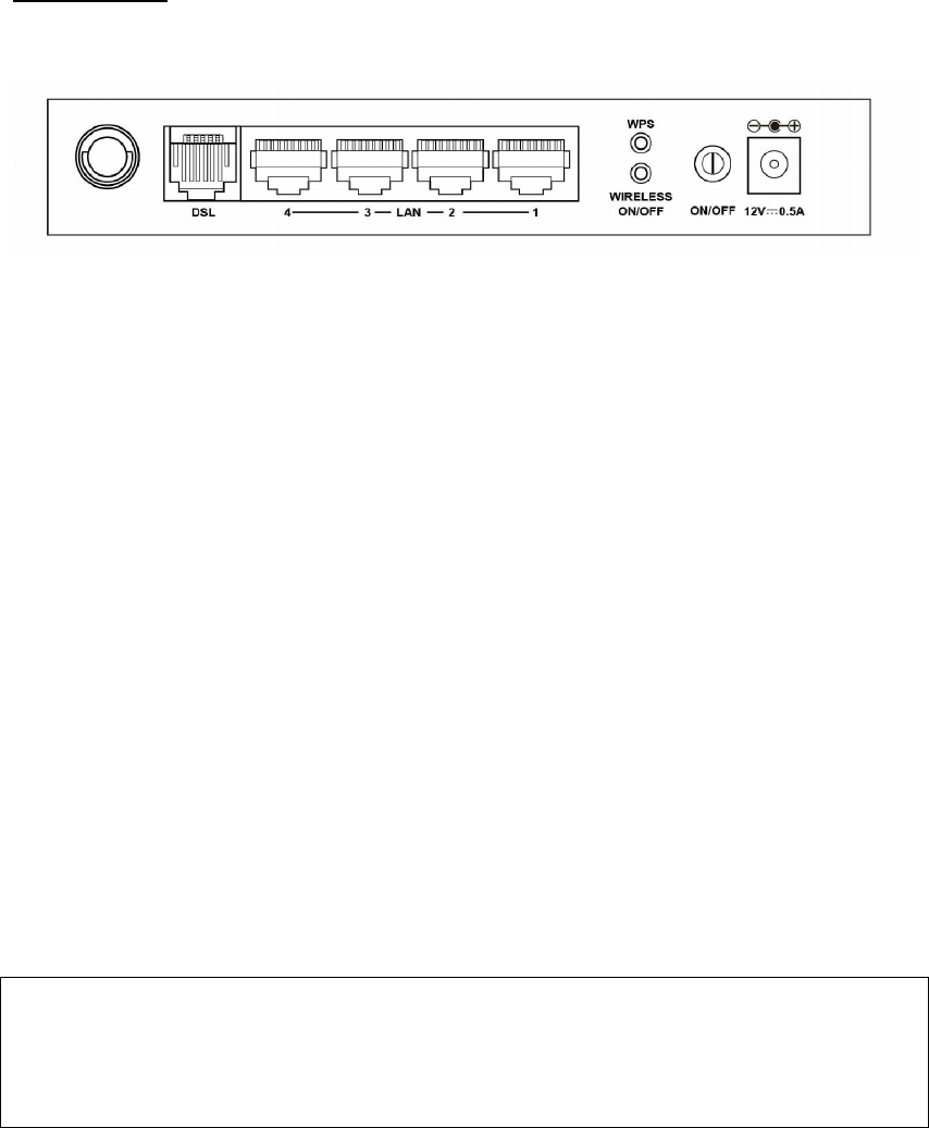
BACK PANEL
The figure below shows the back panel of the device.
DSL
Connect to the DSL port with the DSL RJ11 cable.
LAN (Ethernet) Ports
You can connect the router to up to four LAN devices using RJ45 cables. The ports
are auto-sensing MDI/X and either straight-through or crossover cable can be used.
WPS Button
Press this button to begin searching for WPS clients. These clients must also enable
WPS push button mode (see 6.1.1 WPS for instructions).
WIRELESS
Press this button to enable/disable the wireless LAN (WLAN).
Power ON
Press the power button to the OFF position (OUT). Connect the power adapter to the
power port. Attach the power adapter to a wall outlet or other AC source. Press the
power button to the ON position (IN). If the Power LED displays as expected then
the device is ready for setup (see section Front Panel – LED Indicators).
Caution 1: If the device fails to power up, or it malfunctions, first verify that the
power cords are connected securely and then power it on again. If the
problem persists, contact technical support.
Caution 2: Before servicing or disassembling this equipment, disconnect all power
cords and telephone lines from their outlets.
8
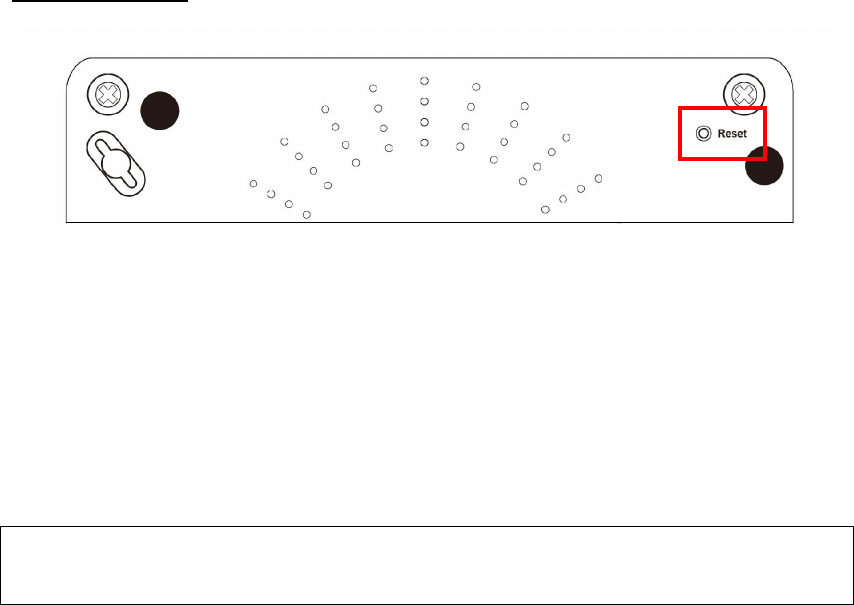
BOTTOM PANEL
Reset Button
Restore the default parameters of the device by pressing the Reset button for 10
seconds. After the device has rebooted successfully, the front panel should display
as expected (see section 2.2 Front Panel2.2 for details).
NOTE: If pressed down for more than 60 seconds, the AR-5389 will go into a
firmware update state (CFE boot mode). The firmware can then be
updated using an Internet browser pointed to the default IP address.
9
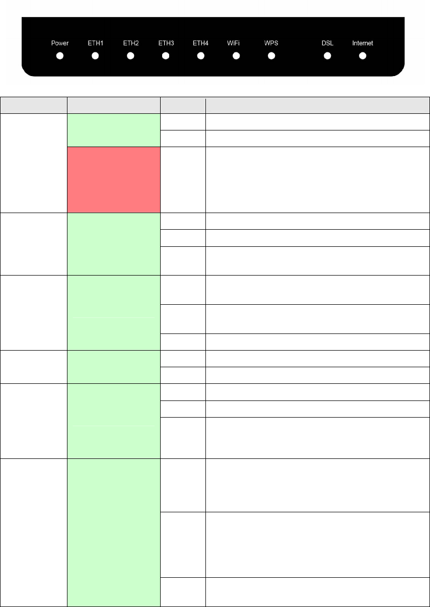
2.2 Front Panel
The front panel LED indicators are shown below and explained in the following table.
This information can be used to check the status of the device and its connections.
LED Color Mode Function
On The device is powered up.
Green
Off The device is powered down.
POWER
Red On
POST (Power On Self Test) failure or other
malfunction. A malfunction is any error of
internal sequence or state that will prevent
the device from connecting to the DSLAM
or passing customer data.
On An Ethernet Link is established.
Off An Ethernet Link is not established.
ETH 1X-4X
Green
Blink Data transmitting or receiving over
Ethernet.
On The wireless module is ready.
(i.e. installed and enabled).
Off The wireless module is not ready.
(i.e. either not installed or disabled).
WiFi Green
Blink Data transmitting or receiving over WIFI.
On WPS function is OK
WPS Green
Off WPS function is closed or failure
On xDSL Link is established.
Off Modem power off.
DSL Green Blink fast: xDSL Link is training or data
transmitting.
slow: xDSL training failed.
On IP connected and no traffic detected. If
an IP or PPPoE session is dropped due to
an idle timeout, the light will remain green
if an ADSL connection is still present.
Off Modem power off, modem in bridged mode
or ADSL connection not present. In
addition, if an IP or PPPoE session is
dropped for any reason, other than an idle
timeout, the light is turned off.
INTERNET
Green
Blink IP connected and IP Traffic is passing
through the device (either direction)
10
Note:
A malfunction is any error of internal sequence or state that will prevent the device
from connecting to the DSLAM or passing customer data. This may be identified at
various times such after power on or during operation through the use of self testing
or in operations which result in a unit state that is not expected or should not occur.
IP connected (the device has a WAN IP address from IPCP or DHCP and DSL is up or
a static IP address is configured, PPP negotiation has successfully complete – if
used – and DSL is up ) and no traffic detected. If the IP or PPPoE session is dropped
for any other reason, the light is turned off. The light will turn red when it attempts
to reconnect and DHCP or PPPoE fails.

11
Chapter 3 Web User Interface
This section describes how to access the device via the web user interface (WUI)
using an Internet browser such as Internet Explorer (version 5.0 and later).
3.1 Default Settings
The factory default settings of this device are summarized below.
LAN IP address: 192.168.1.1
LAN subnet mask: 255.255.255.0
Administrative access (username: root , password: 12345 )
WIFI access: enabled
Technical Note
During power on, the device initializes all settings to default values. It will then
read the configuration profile from the permanent storage section of flash memory.
The default attributes are overwritten when identical attributes with different values
are configured. The configuration profile in permanent storage can be created via
the web user interface or telnet user interface, or other management protocols.
The factory default configuration can be restored either by pushing the reset button
for more than five seconds until the power indicates LED blinking or by clicking the
Restore Default Configuration option in the Restore Settings screen.
3.2 IP Configuration
DHCP MODE
When the AR-5389 powers up, the onboard DHCP server will switch on. Basically,
the DHCP server issues and reserves IP addresses for LAN devices, such as your PC.
To obtain an IP address from the DCHP server, follow the steps provided below.
NOTE: The following procedure assumes you are running Windows XP.
However, the general steps involved are similar for most operating
systems (OS). Check your OS support documentation for further details.
STEP 1: From the Network Connections window, open Local Area Connection (You
may also access this screen by double-clicking the Local Area Connection
icon on your taskbar). Click the Properties button.
STEP 2: Select Internet Protocol (TCP/IP) and click the Properties button.
STEP 3: Select Obtain an IP address automatically as shown below.
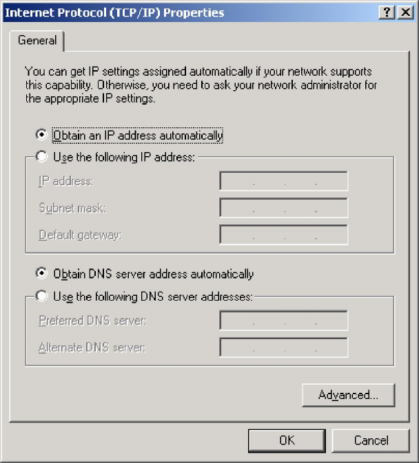
12
STEP 4: Click OK to submit these settings.
If you experience difficulty with DHCP mode, you can try static IP mode instead.
13
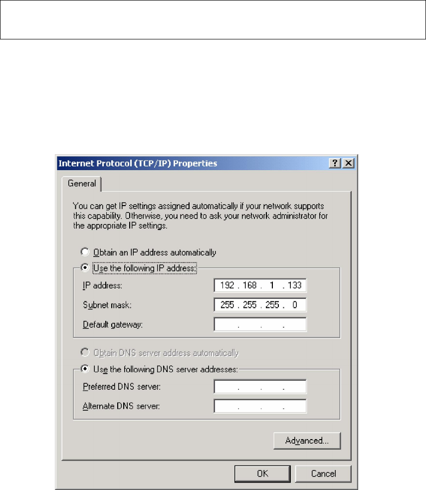
STATIC IP MODE
In static IP mode, you assign IP settings to your PC manually.
Follow these steps to configure your PC IP address to use subnet 192.168.1.x.
NOTE: The following procedure assumes you are running Windows XP.
However, the general steps involved are similar for most operating
systems (OS). Check your OS support documentation for further details.
STEP 1: From the Network Connections window, open Local Area Connection (You
may also access this screen by double-clicking the Local Area Connection
icon on your taskbar). Click the Properties button.
STEP 2: Select Internet Protocol (TCP/IP) and click the Properties button.
STEP 3: Change the IP address to the 192.168.1.x (1<x<255) subnet with subnet
mask of 255.255.255.0. The screen should now display as shown below.
STEP 4: Click OK to submit these settings.
14
3.3 Login Procedure
Perform the following steps to login to the web user interface.
NOTE: The default settings can be found in 3.1 Default Settings.
STEP 1: Start the Internet browser and enter the default IP address for the device
in the Web address field. For example, if the default IP address is
192.168.1.1, type http://192.168.1.1.
NOTE: For local administration (i.e. LAN access), the PC running the browser
must be attached to the Ethernet, and not necessarily to the device.
For remote access (i.e. WAN), use the IP address shown on the Chapter 4
Device Information screen and login with remote username and
password.
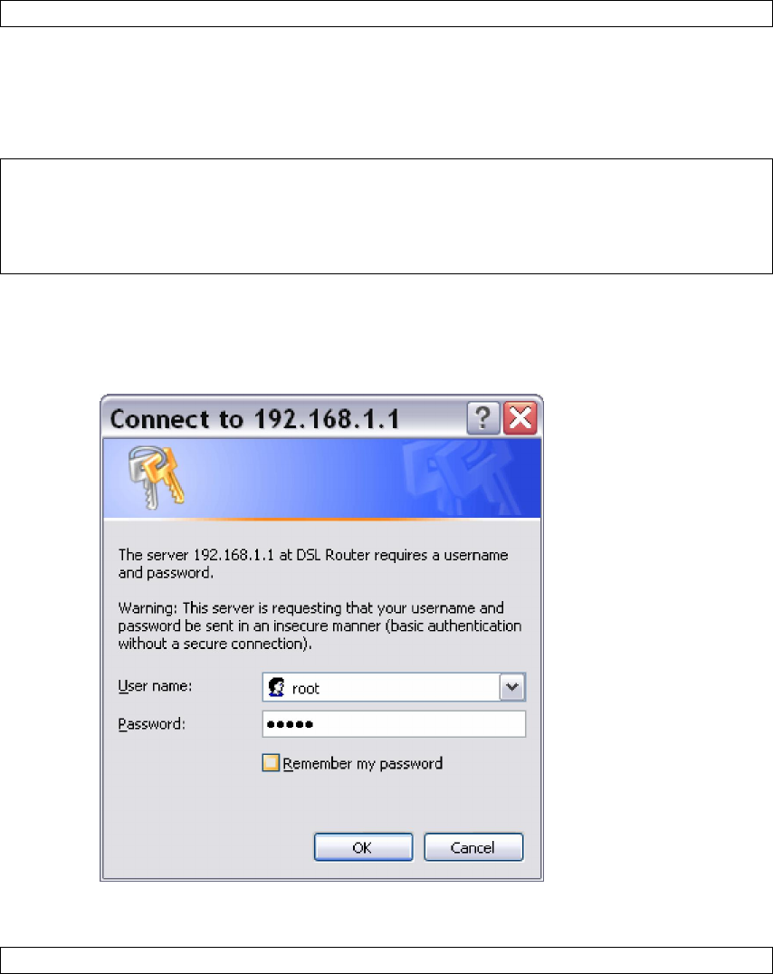
STEP 2: A dialog box will appear, such as the one below. Enter the default
username and password, as defined in section 3.1 Default Settings.
Click OK to continue.
NOTE: The login password can be changed later (see 8.6.1 Passwords).
15
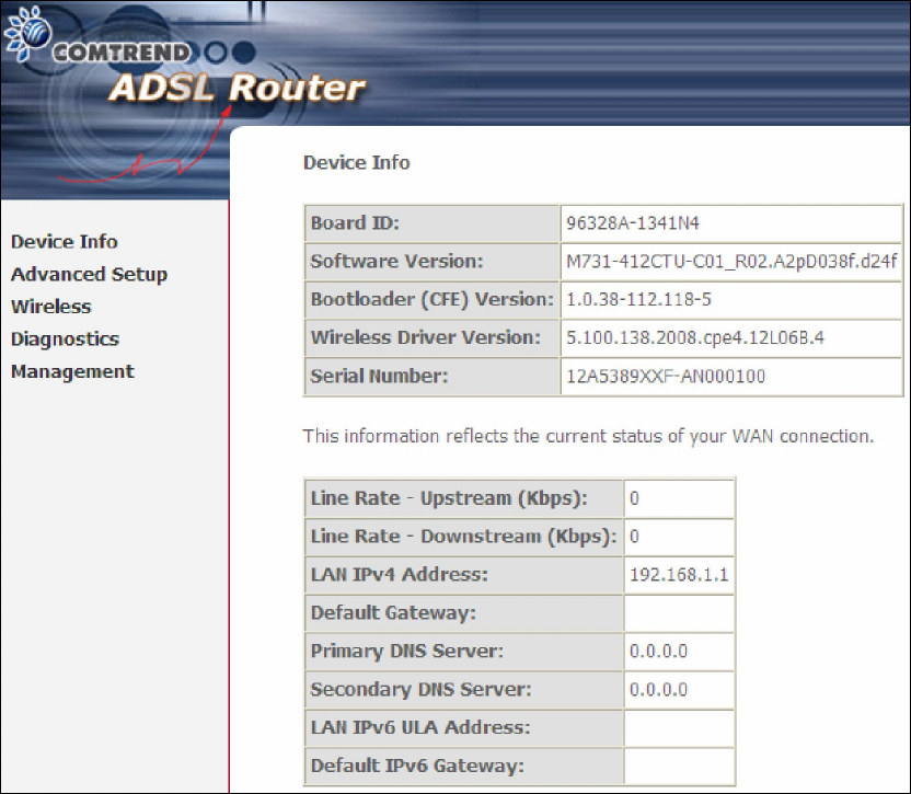
STEP 3: After successfully logging in for the first time, you will reach this screen.
16
Chapter 4 Device Information
The web user interface window is divided into two frames, the main menu (at left)
and the display screen (on the right). The main menu has several options and
selecting each of these options opens a submenu with more selections.
NOTE: The menu items shown are based upon the configured connection(s) and
user account privileges. For example, if NAT and Firewall are enabled, the
main menu will display the NAT and Security submenus. If either is
disabled, their corresponding menu(s) will also be disabled.
Device Info is the first selection on the main menu so it will be discussed first.
Subsequent chapters will introduce the other main menu options in sequence.
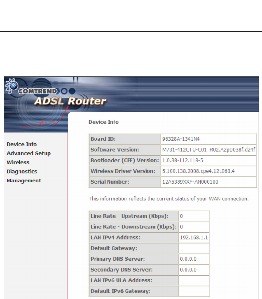
The Device Info Summary screen displays at startup.
This screen shows hardware, software, IP settings and other related information.
17
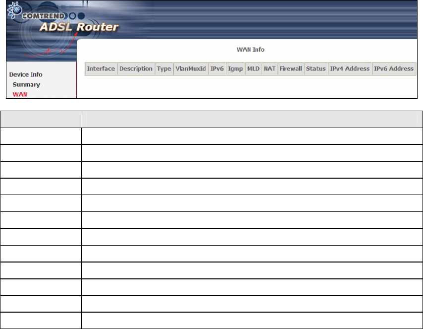
4.1 WAN
Select WAN from the Device Info submenu to display the configured PVC(s).
Heading Description
Interface Name of the interface for WAN
Description Name of the WAN connection
Type Shows the connection type
VlanMuxId Shows 802.1Q VLAN ID
IPv6 Shows WAN IPv6 address
IGMP Shows Internet Group Management Protocol (IGMP) status
MLD Shows Multicast Listener Discovery (MLD) status
NAT Shows Network Address Translation (NAT) status
Firewall Shows the status of Firewall
Status Lists the status of DSL link
IPv4 Address Shows WAN IPv4 address
IPv6 Address Shows WAN IPv6 address
18
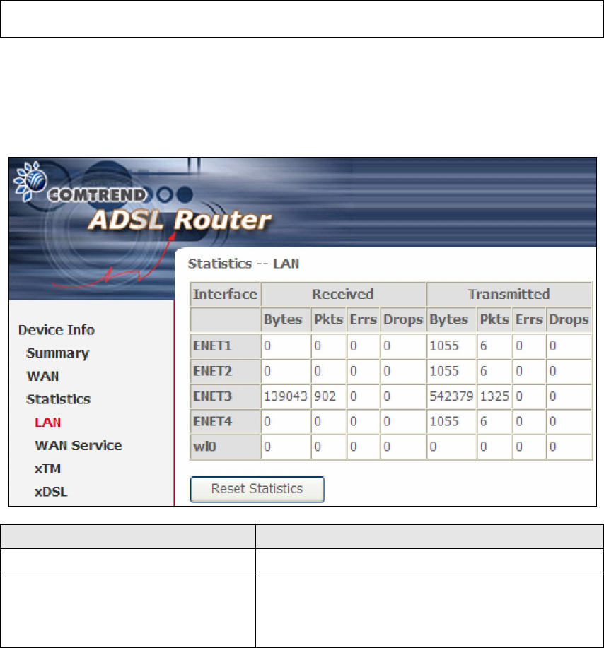
4.2 Statistics
This selection provides LAN, WAN Service, XTM and xDSL statistics.
NOTE: These screens are updated automatically every 15 seconds.
Click Reset Statistics to perform a manual update.
4.2.1 LAN Statistics
This screen shows data traffic statistics for each LAN interface.
Heading Description
Interface LAN interface(s)
Received/Transmitted: - Bytes
- Pkts
- Errs
- Drops
Number of Bytes
Number of Packets
Number of packets with errors
Number of dropped packets
19
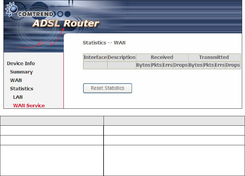
4.2.2 WAN Service Statistics
This screen shows data traffic statistics for each WAN interface.
Heading Description
Interface WAN interfaces
Description WAN service label
Received/Transmitted - Bytes
- Pkts
- Errs
- Drops
Number of Bytes
Number of Packets
Number of packets with errors
Number of dropped packets
20
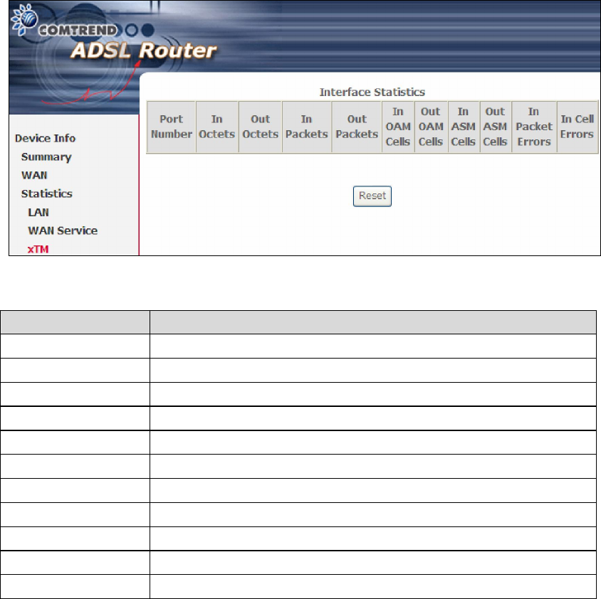
4.2.3 xTM Statistics
The following figure shows Asynchronous Transfer Mode (xTM) statistics.
ATM Interface Statistics
Heading Description
Port Number ATM PORT (0-3)
In Octets Number of octets received over the interface
Out Octets Number of octets transmitted over the interface
In Packets Number of packets received over the interface
Out Packets Number of packets transmitted over the interface
In OAM Cells Number of OAM Cells received over the interface
Out OAM Cells Number of OAM Cells transmitted over the interface
In ASM Cells Number of ASM Cells received over the interface
Out ASM Cells Number of ASM Cells transmitted over the interface
In Packet Errors Number of packets in Error
In Cell Errors Number of cells in Error.
21
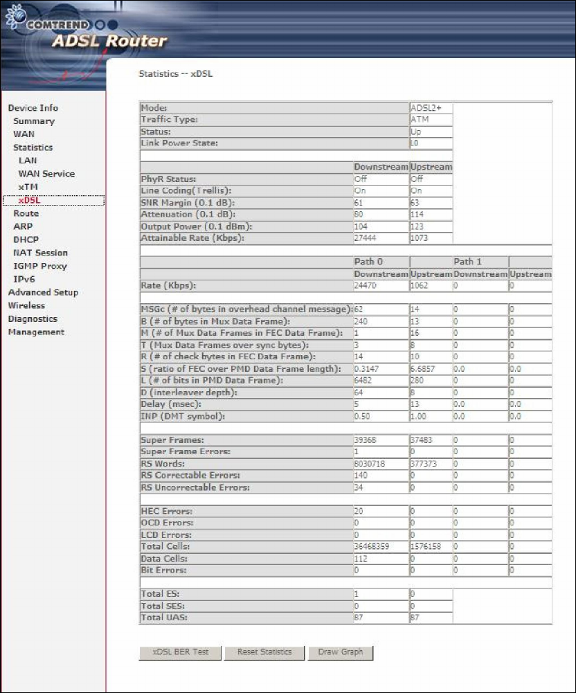
4.2.4 xDSL Statistics
The xDSL Statistics screen displays information corresponding to the xDSL type.
ADSL
Click the Reset Statistics button to refresh this screen.

22
Field Description
Mode G.Dmt, G.lite, T1.413, ADSL2, ADSL2+,
Traffic Type Channel type Interleave or Fast
Status Lists the status of the DSL link
Link Power State Link output power state.
Line Coding (Trellis) Trellis On/Off
SNR Margin (0.1 dB) Signal to Noise Ratio (SNR) margin
Attenuation (0.1 dB) Estimate of average loop attenuation in the downstream
direction.
Output Power
(0.1 dBm)
Total upstream output power
Attainable Rate (Kbps)
The sync rate you would obtain.
Rate (Kbps) Current sync rates downstream/upstream
In ADSL2+ mode, the following section is inserted.
MSGc Number of bytes in overhead channel message
B Number of bytes in Mux Data Frame
M Number of Mux Data Frames in FEC Data Frame
T Mux Data Frames over sync bytes
R Number of check bytes in FEC Data Frame
S Ratio of FEC over PMD Data Frame length
L Number of bits in PMD Data Frame
D The interleaver depth
Delay The delay in milliseconds (msec)
INP DMT symbol
In G.DMT mode, the following section is inserted.
K Number of bytes in DMT frame
R Number of check bytes in RS code word
S RS code word size in DMT frame
D The interleaver depth
Delay The delay in milliseconds (msec)
OH Frames Total number of OH frames
OH Frame Errors Number of OH frames received with errors
RS Words Total number of Reed-Solomon code errors
RS Correctable Errors Total Number of RS with correctable errors
RS Uncorrectable
Errors
Total Number of RS words with uncorrectable errors
HEC Errors Total Number of Header Error Checksum errors
OCD Errors Total Number of Out-of-Cell Delineation errors
23
LCD Errors Total number of Loss of Cell Delineation
Total Cells Total number of ATM cells (including idle + data cells)
Data Cells Total number of ATM data cells
Bit Errors Total number of bit errors
Total ES Total Number of Errored Seconds
Total SES Total Number of Severely Errored Seconds
Total UAS Total Number of Unavailable Seconds
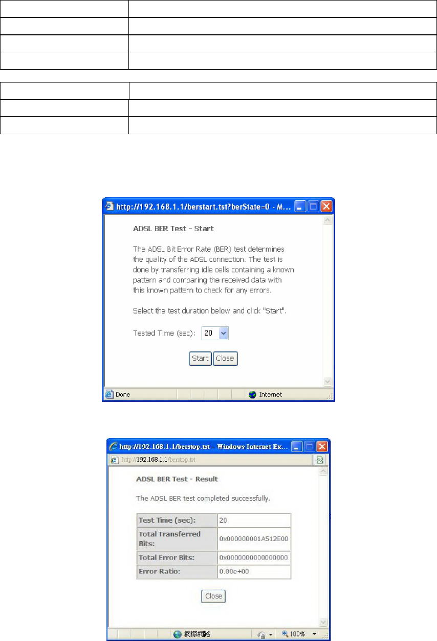
xDSL BER TEST
Click xDSL BER Test on the xDSL Statistics screen to test the Bit Error Rate (BER).
A small pop-up window will open after the button is pressed, as shown below.
Click Start to start the test or click Close to cancel the test. After the BER testing is
complete, the pop-up window will display as follows.
24
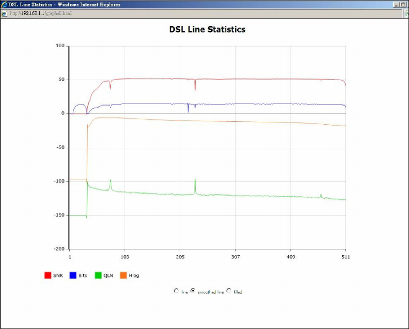
xDSL GRAPH
Click Draw Graph on the xDSL Statistics screen and a pop-up window will display
the xDSL bits per tone status, SNR, QLN and Hlog of the current xDSL connection,
as shown below.
25
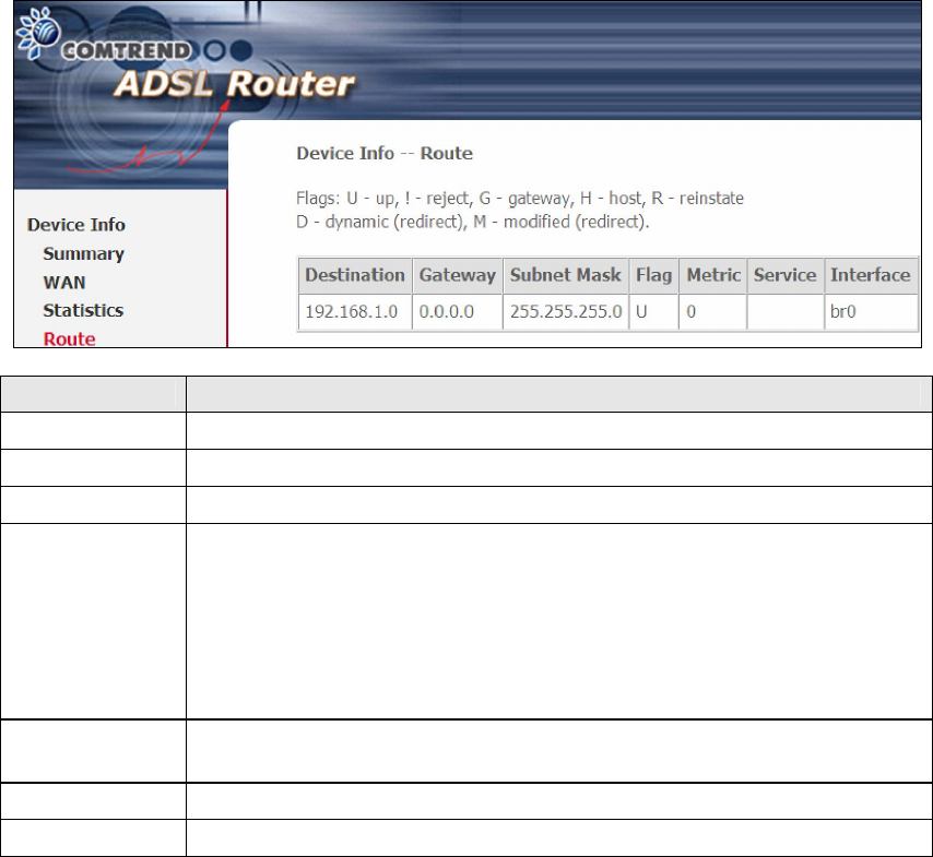
4.3 Route
Choose Route to display the routes that the AR-5389 has found.
Field Description
Destination Destination network or destination host
Gateway Next hub IP address
Subnet Mask Subnet Mask of Destination
Flag U: route is up
!: reject route
G: use gateway
H: target is a host
R: reinstate route for dynamic routing
D: dynamically installed by daemon or redirect
M: modified from routing daemon or redirect
Metric The 'distance' to the target (usually counted in hops). It is not
used by recent kernels, but may be needed by routing daemons.
Service Shows the WAN connection label
Interface Shows connection interfaces
26
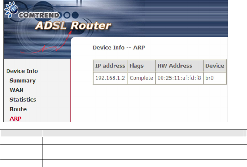
4.4 ARP
Click ARP to display the ARP information.
Field Description
IP address Shows IP address of host pc
Flags Complete, Incomplete, Permanent, or Publish
HW Address
Shows the MAC address of host pc
Device Shows the connection interface
27
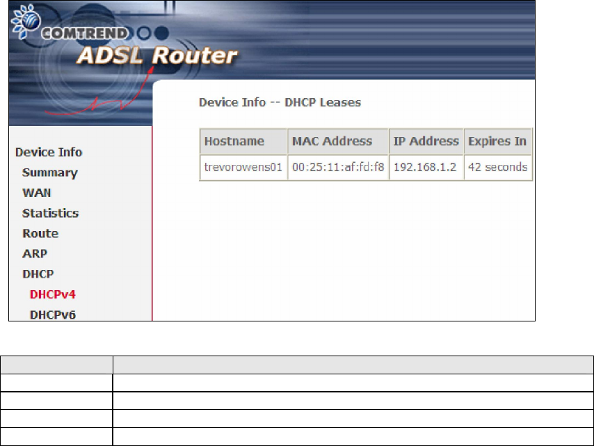
4.5 DHCP
4.5.1 DHCPv4
Click DHCPv4 to display all DHCPv4 Leases.
Field Description
Hostname Shows the device/host/PC network name
MAC Address Shows the Ethernet MAC address of the device/host/PC
IP Address Shows IP address of device/host/PC
Expires In Shows how much time is left for each DHCP Lease
28
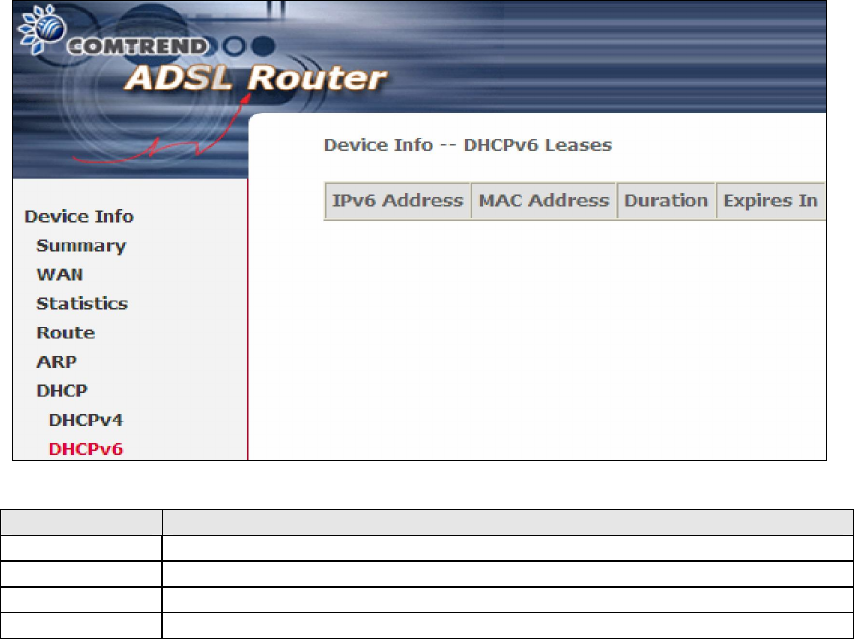
4.5.2 DHCPv6
Click DHCPv6 to display all DHCPv6 Leases.
Field Description
IPv6 Address
Shows IP address of device/host/PC
MAC Address Shows the Ethernet MAC address of the device/host/PC
Duration Shows leased time in hours
Expires In Shows how much time is left for each DHCP Lease

29
4.6 NAT Session
Press "Show All" to show all NAT session information.
Pressing "Show Less" will show NAT session information on the WAN side only.

30
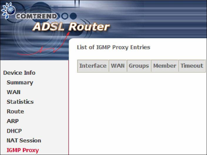
4.7 IGMP Proxy
Displays a list of IGMP Proxy entries.
31
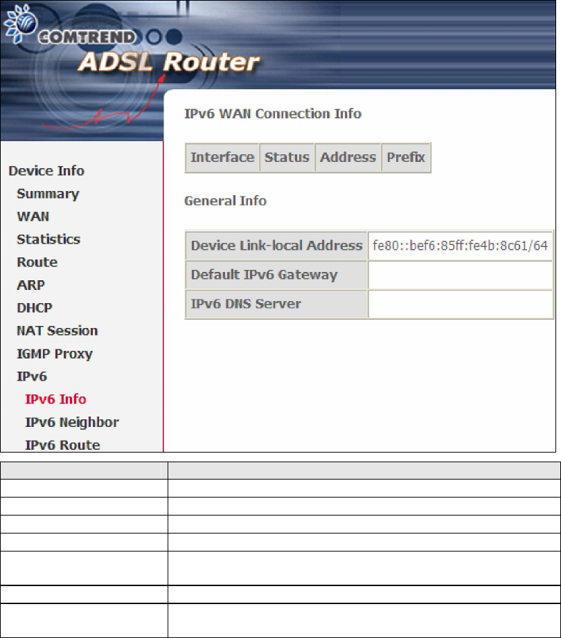
4.8 IPv6
4.8.1 IPv6 Info
Field Description
Interface WAN interface with IPv6 enabled
Status Connection status of the WAN interface
Address IPv6 Address of the WAN interface
Prefix Prefix received/configured on the WAN interface
Device Link-local
Address
The CPE's LAN Address
Default IPv6 Gateway
The default WAN IPv6 gateway
IPv6 DNS Server The IPv6 DNS servers received from the WAN interface
/ configured manually
32
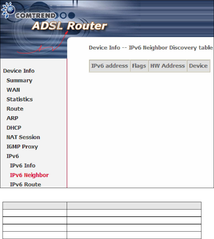
4.8.2 IPv6 Neighbor
Provides a list of IPv6 devices found in the network.
Field Description
IPv6 Address Ipv6 address of the device(s) found
Flags Status of the neighbor device
HW Address MAC address of the neighbor device
Device Interface from which the device is located
33
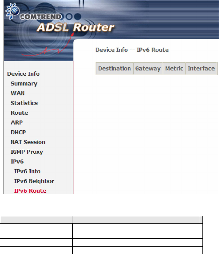
4.8.3 IPv6 Route
Field Description
Destination Destination IP Address
Gateway Gateway address used for destination IP
Metric Metric specified for gateway
Interface Interface used for destination IP
34
Chapter 5 Advanced Setup
5.1 Layer 2 Interface
The ATM interface screen is described here.
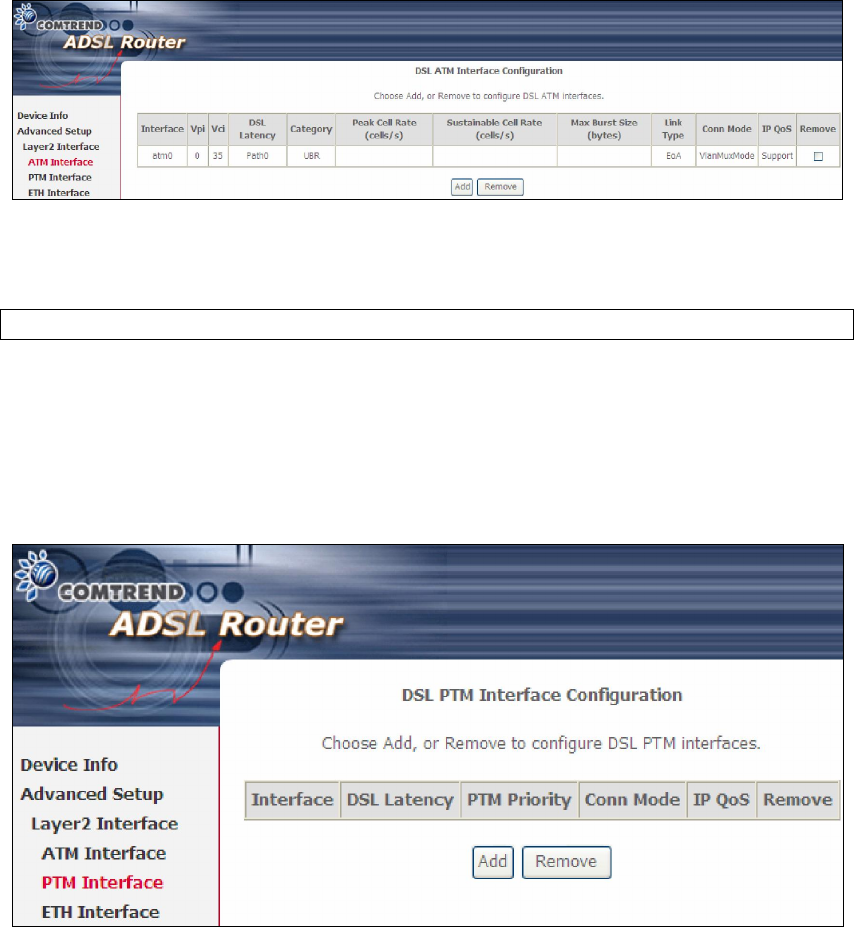
5.1.1 ATM Interface
Add or remove ATM interface connections here.
Click Add to create a new ATM interface (see Appendix E - Connection Setup).
NOTE: Up to 16 ATM interfaces can be created and saved in flash memory.
To remove a connection, select its Remove column radio button and click Remove.
5.1.2 PTM Interface
Add or remove PTM interface connections here.
Click Add to create a new connection (see Appendix E - Connection Setup). To
remove a connection, select its Remove column radio button and click Remove.
35
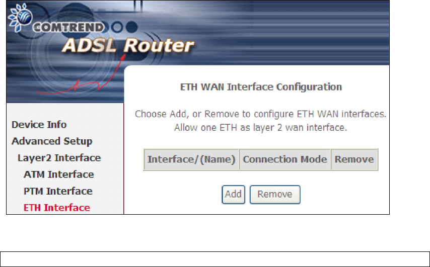
5.1.3 ETH Interface
This screen displays the Ethernet WAN Interface configuration.
Click Add to create a new connection (see Appendix E - Connection Setup).
NOTE: One Ethernet WAN interface can be created and saved in flash memory.
To remove a connection, select its Remove column radio button and click remove.
36
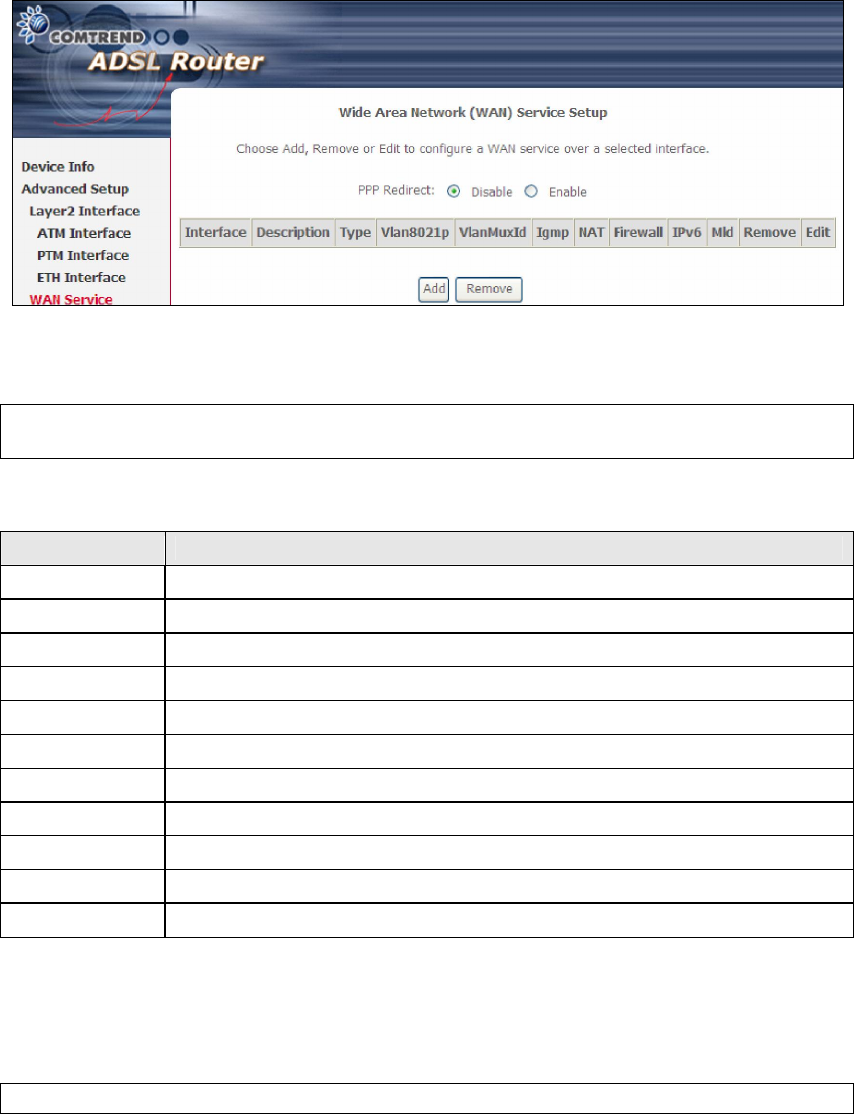
5.2 WAN Service
This screen allows for the configuration of WAN interfaces.
Click the Add button to create a new connection. For connections on ATM or ETH
WAN interfaces see Appendix E - Connection Setup.
NOTE: In Default Mode, up to 16 WAN connections can be configured; while
VLAN Mux Connection Mode supports up to 16 WAN connections.
To remove a connection, select its Remove column radio button and click Remove.
Heading Description
Interface Name of the interface for WAN
Description Name of the WAN connection
Type Shows the connection type
Vlan8021p VLAN ID is used for VLAN Tagging (IEEE 802.1Q)
VlanMuxId Shows 802.1Q VLAN ID
IGMP Shows Internet Group Management Protocol (IGMP) status
NAT Shows Network Address Translation (NAT) status
Firewall Shows the Security status
IPv6 Shows the WAN IPv6 address
MLD Shows Multicast Listener Discovery (MLD) status
Remove Select interfaces to remove
To remove a connection, select its Remove column radio button and click Remove.
To Add a new WAN connection, click the Add button and follow the instructions.
NOTE: Up to 16 PVC profiles can be configured and saved in flash memory.
37
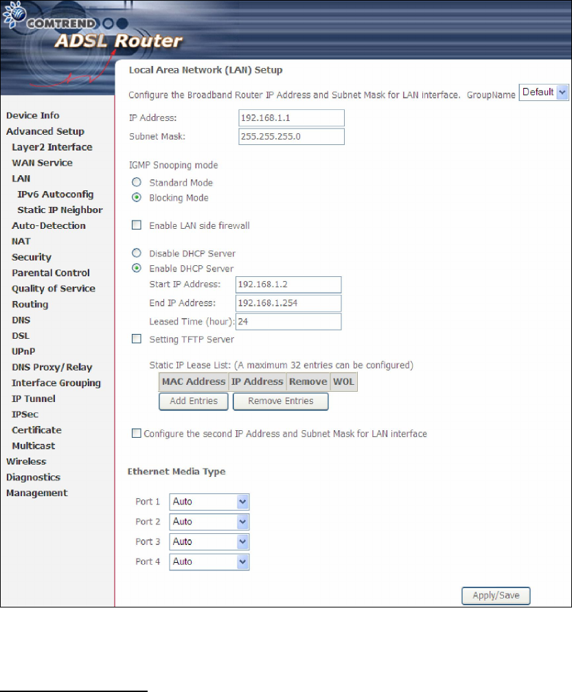
5.3 LAN
Configure the LAN interface settings and then click Apply/Save.
Consult the field descriptions below for more details.
GroupName: Select an Interface Group.
1st LAN INTERFACE
IP Address: Enter the IP address for the LAN port.
Subnet Mask: Enter the subnet mask for the LAN port.
Enable IGMP Snooping: Enable by ticking the checkbox .
Standard Mode: In standard mode, multicast traffic will flood to all
bridge ports when no client subscribes to a multicast
group – even if IGMP snooping is enabled.
38
Blocking Mode: In blocking mode, the multicast data traffic will be
blocked and not flood to all bridge ports when there are
no client subscriptions to any multicast group.
Enable LAN side firewall: Enable by ticking the checkbox .
DHCP Server: To enable DHCP, select Enable DHCP server and enter Start and
End IP addresses and the Leased Time. This setting configures the
router to automatically assign IP, default gateway and DNS server
addresses to every PC on your LAN.
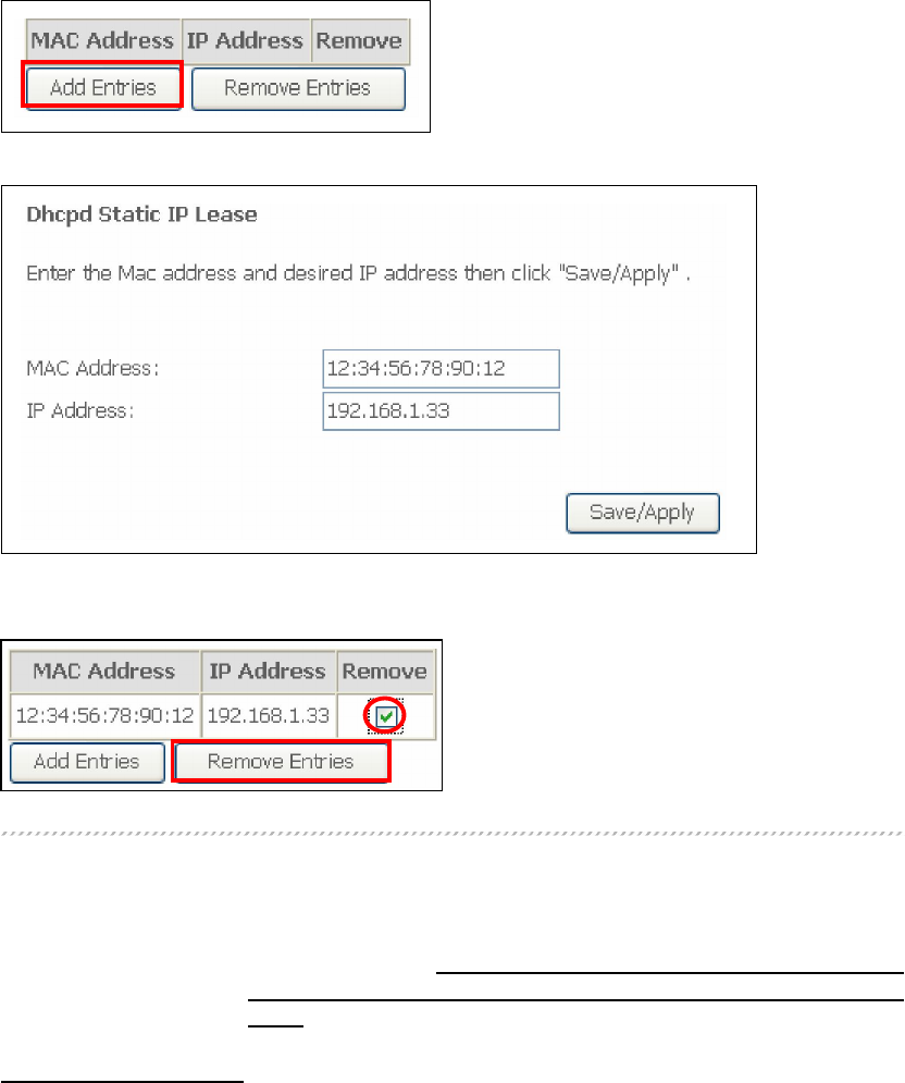
Static IP Lease List: A maximum of 32 entries can be configured.
To add an entry, enter MAC address and Static IP and then click Save/Apply.
To remove an entry, tick the corresponding checkbox in the Remove column and
then click the Remove Entries button, as shown below.
DHCP Server Relay: Enable with checkbox and enter DHCP Server IP address.
This allows the Router to relay the DHCP packets to the
remote DHCP server. The remote DHCP server will provide
the IP address. This option is hidden if NAT is enabled
or when the router is configured with only one Bridge
PVC.
2ND LAN INTERFACE
To configure a secondary IP address, tick the checkbox outlined (in RED) below.
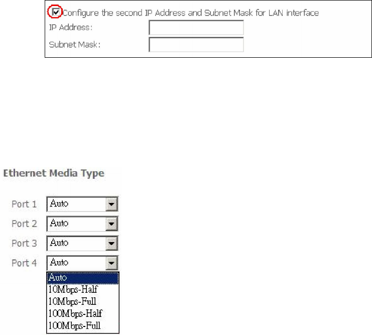
39
IP Address: Enter the secondary IP address for the LAN port.
Subnet Mask: Enter the secondary subnet mask for the LAN port.
Ethernet Media Type:
Configure auto negotiation, or enforce selected speed and duplex mode for each
Ethernet port.
40
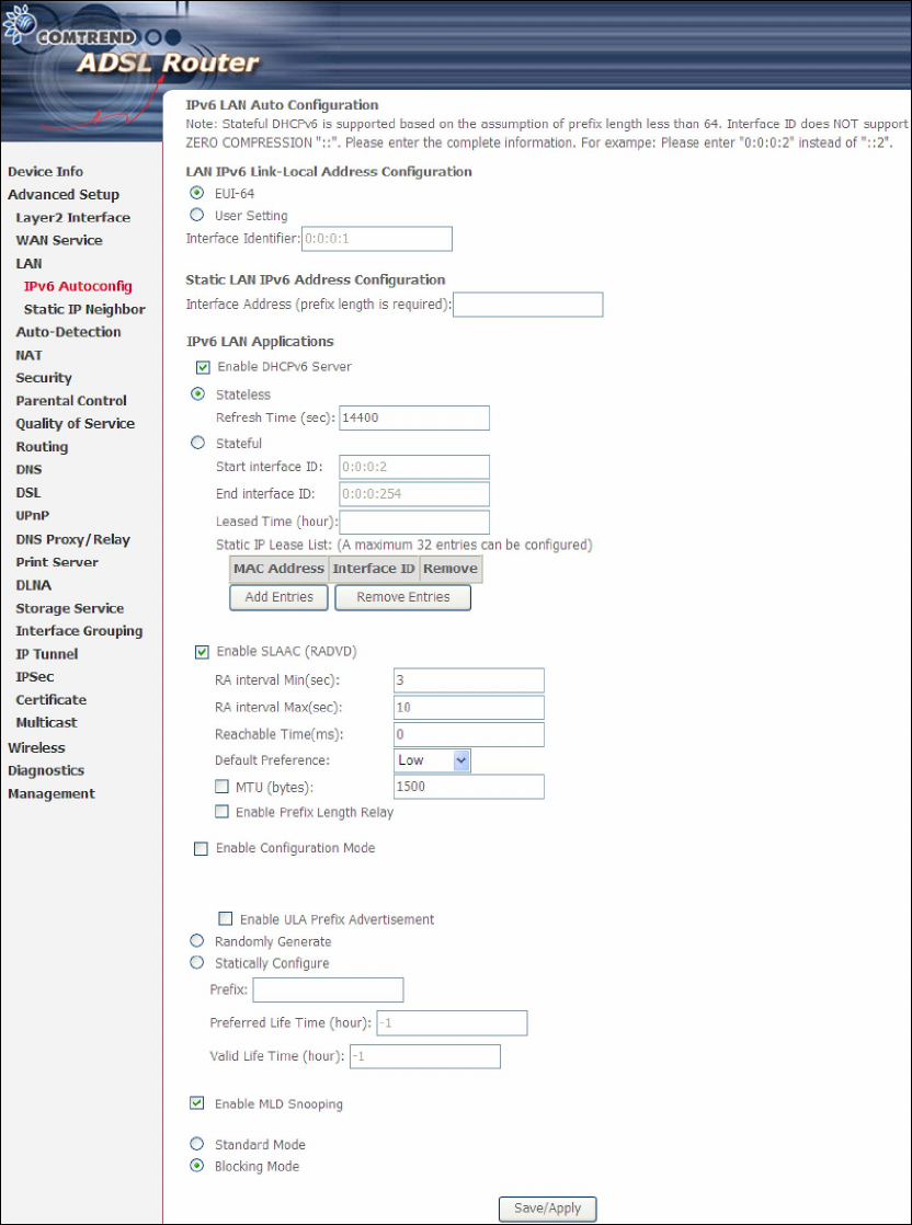
5.3.1 LAN IPv6 Autoconfig
Configure the LAN interface settings and then click Apply/Save.
Consult the field descriptions below for more details.
LAN IPv6 Link-Local Address Configuration
41
Heading Description
EUI-64 Use EUI-64 algorithm to calculate link-local address from MAC
address
User Setting Use the Interface Identifier field to define a link-local address
Static LAN IPv6 Address Configuration
Heading Description
Interface Address
(prefix length is
required):
Configure static LAN IPv6 address and subnet prefix
length
IPv6 LAN Applications
Heading Description
Stateless Use stateless configuration
Refresh Time (sec): The information refresh time option specifies how long a
client should wait before refreshing information retrieved
from DHCPv6
Stateful Use stateful configuration
Start interface ID: Start of interface ID to be assigned to dhcpv6 client
End interface ID: End of interface ID to be assigned to dhcpv6 client
Leased Time (hour): Lease time for dhcpv6 client to use the assigned IP address
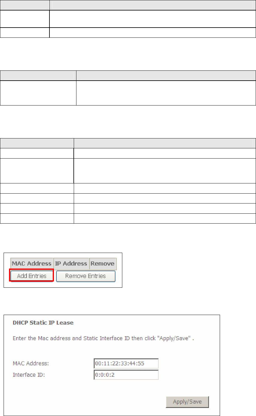
Static IP Lease List: A maximum of 32 entries can be configured.
To add an entry, enter MAC address and Static IP and then click Save/Apply.
42
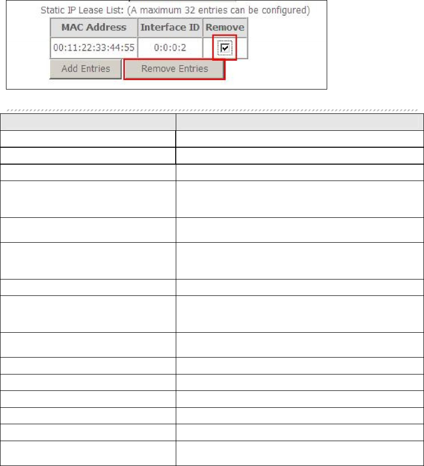
To remove an entry, tick the corresponding checkbox in the Remove column and
then click the Remove Entries button, as shown below.
Heading Description
Enable RADVD Enable use of router advertisement daemon
RA interval Min(sec): Minimum time to send router advertisement
RA interval Max(sec): Maximum time to send router advertisement
Reachable Time(ms): The time, in milliseconds that a neighbor is
reachable after receiving reachability
confirmation
Default Preference: Preference level associated with the default
router
MTU (bytes): MTU value used in router advertisement
messages to insure that all nodes on a link use
the same MTU value
Enable Prefix Length Relay Use prefix length receive from WAN interface
Enable Configuration Mode Manually configure prefix, prefix length,
preferred lifetime and valid lifetime used in
router advertisement
Enable ULA Prefix Advertisement
Allow RADVD to advertise Unique Local Address
Prefix
Randomly Generate Use a Randomly Generated Prefix
Statically Configure Prefix Specify the prefix to be used
Statically Configure The prefix to be used
Preferred Life Time (hour) The preferred life time for this prefix
Valid Life Time (hour) The valid life time for this prefix
Enable MLD Snooping Enable/disable IPv6 multicast forward to LAN
ports
43
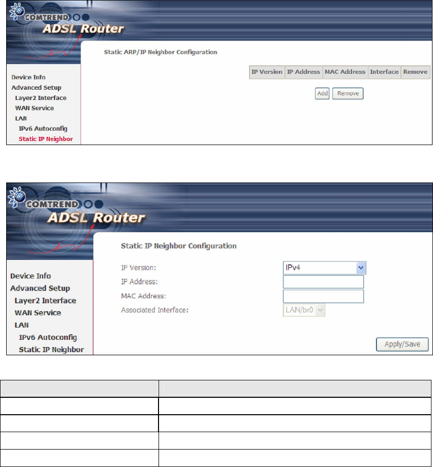
5.3.2 Static IP Neighbor
Click the Add button to display the following.
Heading Description
IP Version The IP version used for the neighbor device
IP Address Define the IP Address for the neighbor device
MAC Address The MAC Address of the neighbor device
Associated Interface The interface where the neighbor device is located
44
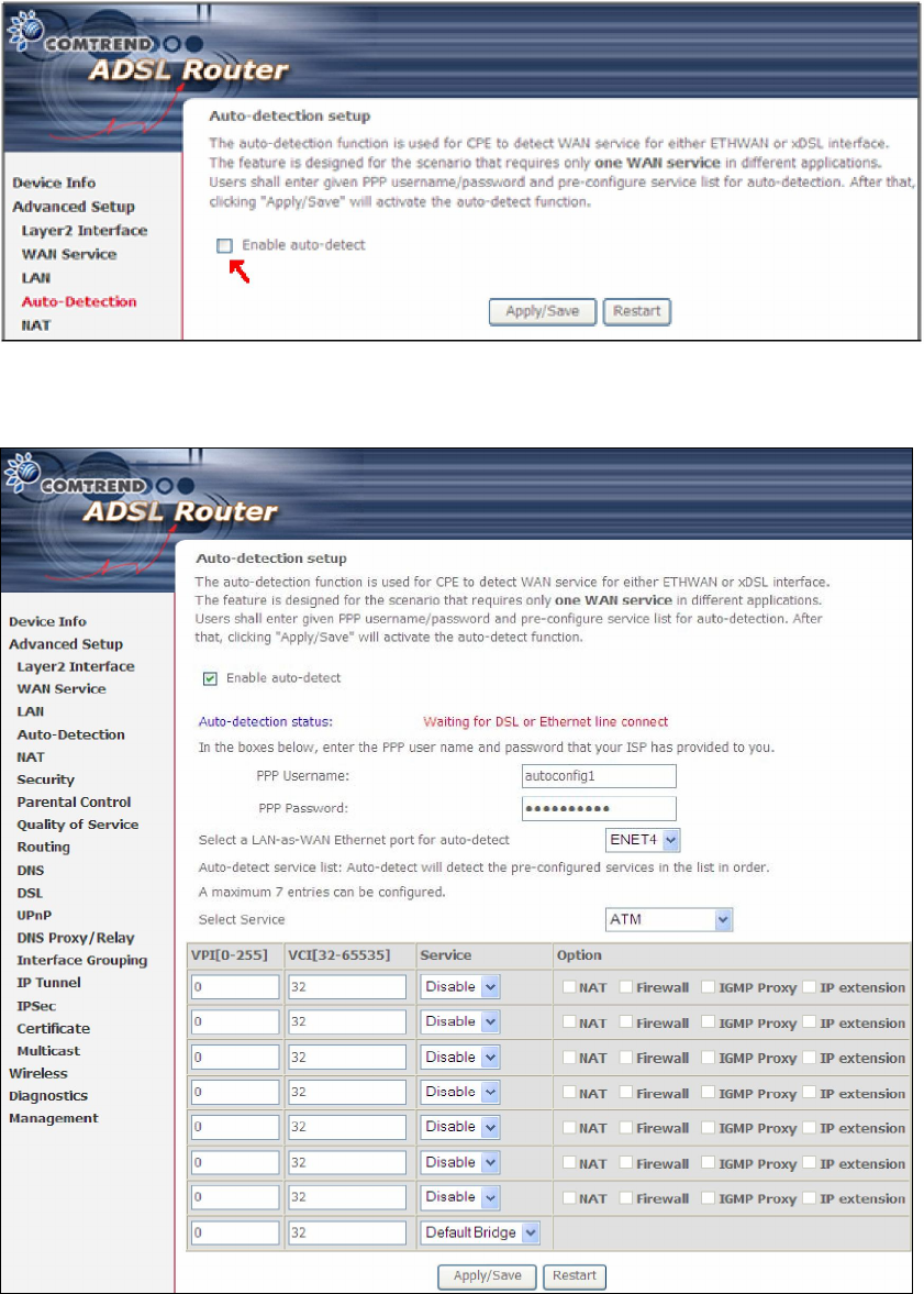
5.4 Auto-Detection
The auto-detection function is used for CPE to detect WAN service for either
ETHWAN or xDSL interface. The feature is designed for the scenario that requires
only one WAN service in different applications.
The Auto Detection page simply provides a checkbox allowing users to enable or
disable the feature. Check the checkbox to display the following configuration
options.
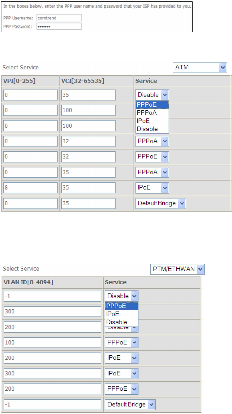
45
Enter the PPP username/password given by your service provider for PPP service
detection.
WAN services list for ATM mode: A maximum of 7 WAN services with
corresponding PVC are required to be configured for ADSL ATM mode. The services
will be detected in order. Users can modify the 7 pre-configured services and select
disable to ignore any of those services to meet their own requirement and also
reduce the detection cycle.
46
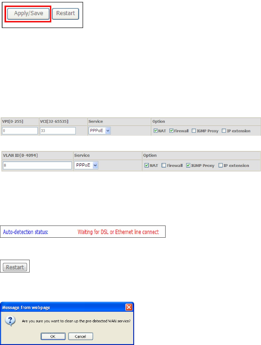
WAN services list for PTM mode: A maximum of 7 WAN services with
corresponding VLAN ID (-1 indicates no VLAN ID is required for the service) are
required to be configured for ADSL/VDSL PTM mode and ETHWAN. The services will
be detected in order. Users can modify the 7 pre-configured services and select
disable to ignore any of those services to meet their own requirement and also
reduce the detection cycle.
Click "Apply/Save" to activate the auto-detect function.
Options for each WAN service: These options are selectable for each WAN
service. Users can pre-configure both WAN services and other provided settings to
meet their deployed requirements.
Auto Detection status and Restart
The Auto-detection status is used to display the real time status of the
Auto-detection feature.
The Restart button is used to detect all the WAN services that are either detected
by the auto-detection feature or configured manually by users.
The following window will pop up upon clicking the Restart button. Click the OK
button to proceed.
47
Auto Detection notice
1) This feature will automatically detect one WAN service only. If customers require
multiple WAN services, manual configuration is required.
2) If a physical ETHWAN port is detected, the Auto Detection for ETHWAN will be
fixed on the physical ETHWAN port and cannot be configured for any LAN port;
if the physical ETHWAN port is not detected, the Auto Detection for ETHWAN will
be configured to the 4th LAN port by default and allows it to be configured for any
LAN port as well.
3) For cases in which both the DSL port and ETHWAN port are plugged in at the
same time, the DSL WAN will have priority over ETHWAN. For example, the
ETHWAN port is plugged in with a WAN service detected automatically and then
the DSL port is plugged in and linked up. The Auto Detection feature will clear
the WAN service for ETHWAN and re-detect the WAN service for DSL port.
4) If none of the pre-configured services are detected, a Bridge service will be
created.
48
5.5 NAT
To display this option, NAT must be enabled in at least one PVC shown on the
Chapter 5 Advanced Setup

49
4.5.2 DHCPv6
Click DHCPv6 to display all DHCPv6 Leases.
Field Description
IPv6 Address
Shows IP address of device/host/PC
MAC Address Shows the Ethernet MAC address of the device/host/PC
Duration Shows leased time in hours
Expires In Shows how much time is left for each DHCP Lease
50
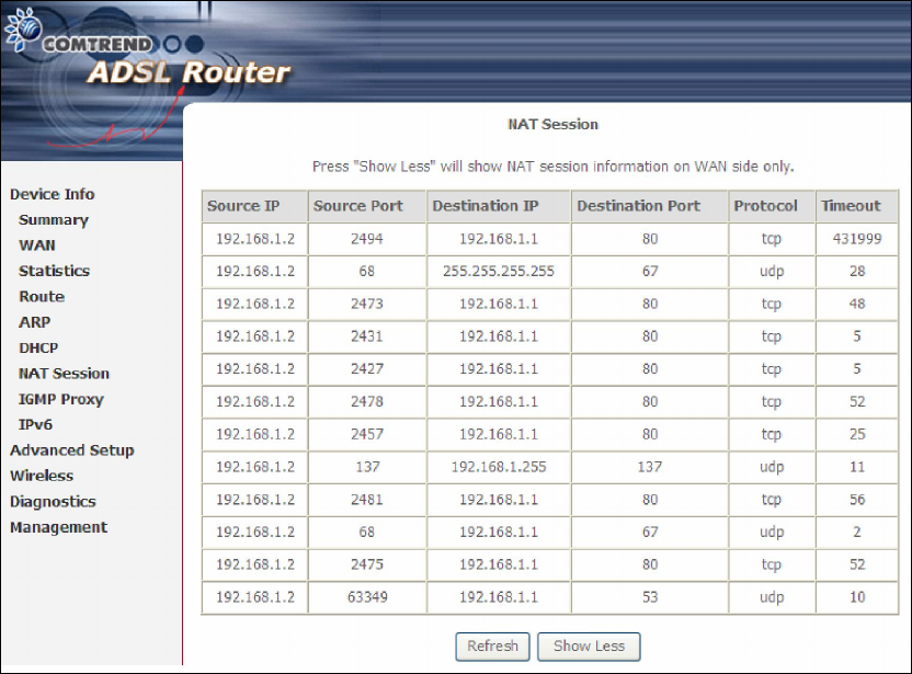
4.6 NAT Session
Press "Show All" to show all NAT session information.
Pressing "Show Less" will show NAT session information on the WAN side only.
51
4.7 IGMP Proxy
Displays a list of IGMP Proxy entries.

52
4.8 IPv6
4.8.1 IPv6 Info
Field Description
Interface WAN interface with IPv6 enabled
Status Connection status of the WAN interface
Address IPv6 Address of the WAN interface
Prefix Prefix received/configured on the WAN interface
Device Link-local
Address
The CPE's LAN Address
Default IPv6 Gateway
The default WAN IPv6 gateway
IPv6 DNS Server The IPv6 DNS servers received from the WAN interface
/ configured manually

53
4.8.2 IPv6 Neighbor
Provides a list of IPv6 devices found in the network.
Field Description
IPv6 Address Ipv6 address of the device(s) found
Flags Status of the neighbor device
HW Address MAC address of the neighbor device
Device Interface from which the device is located

54
4.8.3 IPv6 Route
Field Description
Destination Destination IP Address
Gateway Gateway address used for destination IP
Metric Metric specified for gateway
Interface Interface used for destination IP
55
Chapter 5 Advanced Setup - . NAT is not an available option in Bridge mode.
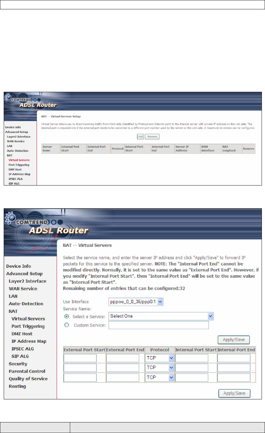
5.5.1 Virtual Servers
Virtual Servers allow you to direct incoming traffic from the WAN side (identified by
Protocol and External port) to the internal server with private IP addresses on the
LAN side. The Internal port is required only if the external port needs to be
converted to a different port number used by the server on the LAN side.
A maximum of 32 entries can be configured.
To add a Virtual Server, click Add. The following will be displayed.
Consult the table below for field and header descriptions.
Field/Header Description

56
Field/Header Description
Use Interface Select a WAN interface from the drop-down box.
Select a Service
Or
Custom Service
User should select the service from the list.
Or
User can enter the name of their choice.
Server IP Address Enter the IP address for the server.
External Port Start Enter the starting external port number (when you select
Custom Server). When a service is selected, the port ranges
are automatically configured.
External Port End Enter the ending external port number (when you select
Custom Server). When a service is selected, the port ranges
are automatically configured.
Protocol TCP, TCP/UDP, or UDP.
Internal Port Start Enter the internal port starting number (when you select
Custom Server). When a service is selected the port ranges
are automatically configured
Internal Port End Enter the internal port ending number (when you select
Custom Server). When a service is selected, the port ranges
are automatically configured.
57
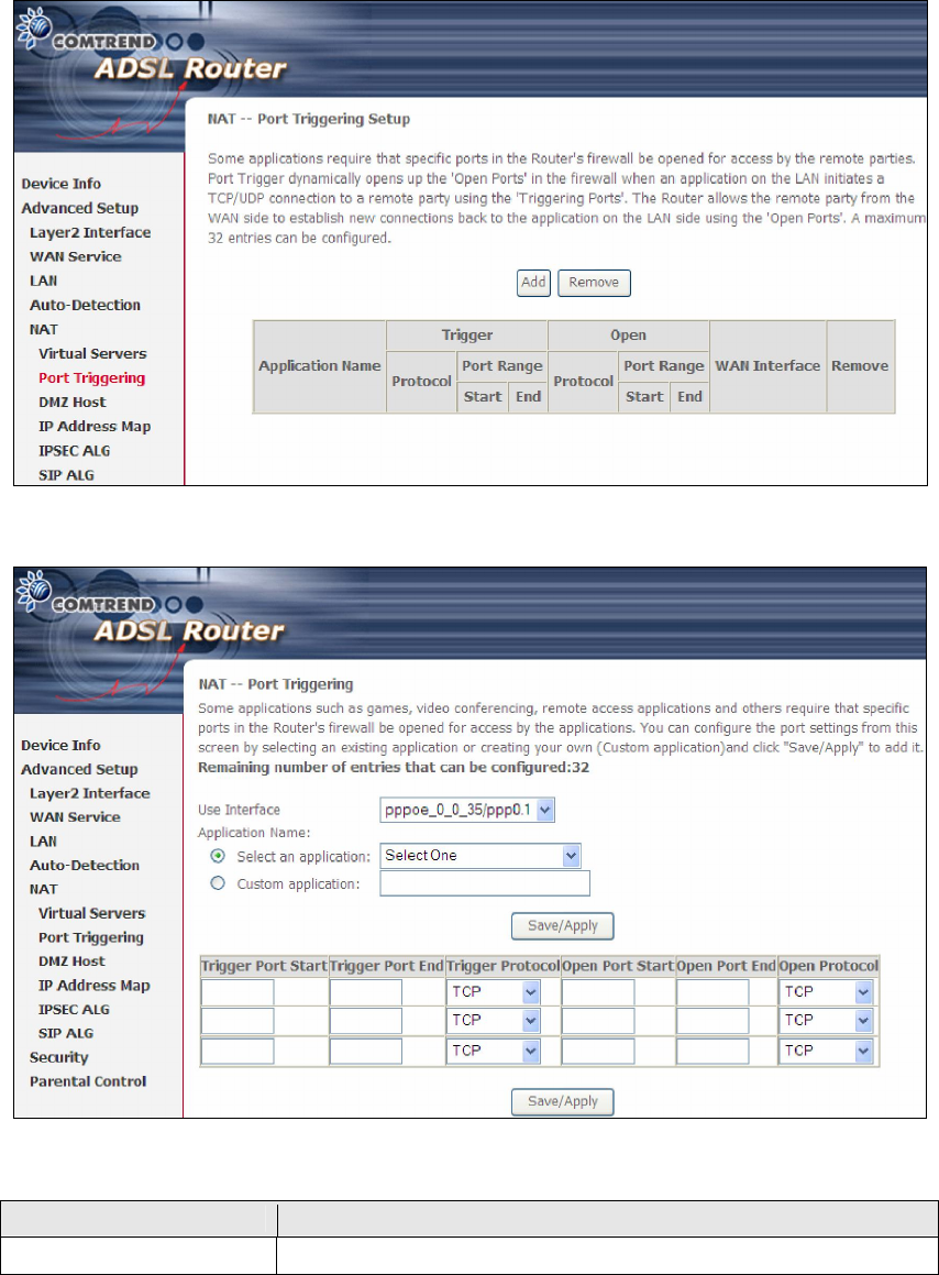
5.5.2 Port Triggering
Some applications require that specific ports in the firewall be opened for access by
the remote parties. Port Triggers dynamically 'Open Ports' in the firewall when an
application on the LAN initiates a TCP/UDP connection to a remote party using the
'Triggering Ports'. The Router allows the remote party from the WAN side to
establish new connections back to the application on the LAN side using the 'Open
Ports'. A maximum 32 entries can be configured.
To add a Trigger Port, click Add. The following will be displayed.
Consult the table below for field and header descriptions.
Field/Header Description
Use Interface Select a WAN interface from the drop-down box.

58
Field/Header Description
Select an Application
Or
Custom Application
User should select the application from the list.
Or
User can enter the name of their choice.
Trigger Port Start Enter the starting trigger port number (when you select
custom application). When an application is selected, the
port ranges are automatically configured.
Trigger Port End Enter the ending trigger port number (when you select
custom application). When an application is selected, the
port ranges are automatically configured.
Trigger Protocol TCP, TCP/UDP, or UDP.
Open Port Start Enter the starting open port number (when you select
custom application). When an application is selected, the
port ranges are automatically configured.
Open Port End Enter the ending open port number (when you select
custom application). When an application is selected, the
port ranges are automatically configured.
Open Protocol TCP, TCP/UDP, or UDP.
59
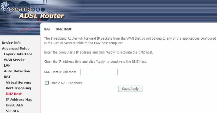
5.5.3 DMZ Host
The DSL router will forward IP packets from the WAN that do not belong to any of
the applications configured in the Virtual Servers table to the DMZ host computer.
To Activate the DMZ host, enter the DMZ host IP address and click Save/Apply.
To Deactivate the DMZ host, clear the IP address field and click Save/Apply.