DETECTION MONITORING TECHNOLOGIES AIMSFS-05X AIMS FAST SCAN RADAR SYSTEM (AIMSFS-05X) User Manual AIMS FS Radar I O Manual v1 0
DETECTION MONITORING TECHNOLOGIES, LLC (dba DMT, LLC) AIMS FAST SCAN RADAR SYSTEM (AIMSFS-05X) AIMS FS Radar I O Manual v1 0
Contents
Installation Guide 1

DMT, LLC • DMT-M200-311 • 08/2009
August 5, 2009
DMT LLC
45180 Business Court, Suite 500
Sterling, VA 20166
703-326-0004
703-326-0022
sales@dmtllc.com
DMT is a private company owned entirely by USA Citizens
DMT radar systems are manufactured entirely in the USA
AIMS Fast-Scan Radar
v3.22
Installation and Configuration
Manual
Reference Number: DMT-M200-311

AIMS Fast-Scan Radar v3.22 Installation and Operations Manual
DMT, LLC • DMT-M200-311 • 08/2009
Change History
Version
Date
Status
Author
Description
0.1
12/23/2008
DRAFT
J Byrne
0.2
06/30/2011
RELEASE
J Byrne
FCC
-
related statements added

AIMS Fast-Scan Radar v3.22 Installation and Operations Manual
DMT, LLC • DMT-M200-311 • 06/2009
i
Table of Contents
1 Introduction ....................................................................... Error! Bookmark not defined.
1.1 Radar Configurations ...................................................... Error! Bookmark not defined.
1.1.1 Transmit Power ........................................................ Error! Bookmark not defined.
1.1.2 Operating Frequency ................................................ Error! Bookmark not defined.
1.1.3 Physical Packaging .................................................. Error! Bookmark not defined.
1.2 Antennae.......................................................................... Error! Bookmark not defined.
1.3 AIMS Universal Communication Module ...................... Error! Bookmark not defined.
1.4 Other Value-Added Enhancements ................................. Error! Bookmark not defined.
2 Reference .......................................................................................................................... 1
2.1 Documents ........................................................................................................................ 1
2.2 Acronyms and Definitions ............................................................................................... 1
3 Installation ......................................................................................................................... 3
3.1 General Guidelines ........................................................................................................... 3
3.1.1 Cabling ...................................................................................................................... 3
3.1.2 Power Cabling ........................................................................................................... 4
3.1.3 Communications ....................................................................................................... 4
3.1.4 Selecting a Location .................................................................................................. 6
3.1.5 Installation on Towers, Buildings, or Poles .............................................................. 6
3.2 Preparation ....................................................................................................................... 9
3.2.1 Before You Begin ..................................................................................................... 9
3.2.2 Tools ......................................................................................................................... 9
3.2.3 Arrival of Equipment .............................................................................................. 10
3.3 Mounting the Radar ........................................................................................................ 12
3.3.1 Installation Procedures for AIMS Fast-Scan .......................................................... 12
3.4 Locating the UCM .......................................................................................................... 13
3.5 Camera Installation ........................................................................................................ 14
3.6 Connecting Power .......................................................................................................... 17
3.6.1 Radar ....................................................................................................................... 17
3.6.2 Cameras................................................................................................................... 17

AIMS Fast-Scan Radar v3.22 Installation and Operations Manual
DMT, LLC • DMT-M200-311 • 06/2009
ii
3.6.3 Universal Communications Module and Utility Enclosures .................................. 17
3.7 Hardware Adjustments ................................................................................................... 18
3.7.1 Adjusting the Azimuth Home Pin ........................................................................... 19
3.7.2 Adjusting the Elevation Home Pin ......................................................................... 20
4 Server Software ..................................................................................................................... 21
4.1 Configurable Features .................................................................................................... 21
4.2 Server Interface Screens ................................................................................................. 22
4.2.1 Operation Tab ......................................................................................................... 24
4.2.1.1 Processing Parameters ..................................................................................... 24
4.2.1.2 GPS Parameters ............................................................................................... 25
4.2.1.3 Auto Scan Control ........................................................................................... 25
4.2.1.4 Camera Parameters .......................................................................................... 26
4.2.1.5 GPS/Compass Installed ................................................................................... 26
4.2.1.6 System Status ................................................................................................... 26
4.2.1.7 Restore Factory Settings .................................................................................. 27
4.2.2 Waveform Tab ........................................................................................................ 28
4.2.2.1 Waveform Settings .......................................................................................... 28
4.2.2.2 Radar Settings .................................................................................................. 29
4.2.2.3 A/D Board Options .......................................................................................... 30
4.2.3 Networking Tab ...................................................................................................... 31
4.2.4 Graphing Tab .......................................................................................................... 32
4.2.4.1 Select Graph Type ........................................................................................... 32
4.2.4.2 Set FFT Graph Options.................................................................................... 33
4.2.4.3 Set Line Graph Options ................................................................................... 33
4.2.4.4 Setup Main Lobe Removal .............................................................................. 34
4.2.4.5 Setup 2
nd
/3
rd
Lobe Removal ............................................................................ 35
4.2.4.6 Apply Normalization ....................................................................................... 35
4.2.4.7 Other Installation Parameters .......................................................................... 35
4.2.5 DSP Tab .................................................................................................................. 37
4.2.5.1 Motion Compensation ..................................................................................... 37
4.2.5.2 A/D Sample Rate ............................................................................................. 38
4.2.5.3 Matched Filter.................................................................................................. 38

AIMS Fast-Scan Radar v3.22 Installation and Operations Manual
DMT, LLC • DMT-M200-311 • 06/2009
iii
4.2.5.4 Smoothing Filter .............................................................................................. 39
4.2.5.5 FFT Options (disabled) .................................................................................... 39
4.2.5.6 Ramp Functions ............................................................................................... 39
4.2.5.7 Interlace Processing ......................................................................................... 40
4.2.5.8 Auto Lobe Report ............................................................................................ 41
4.2.6 Files Tab.................................................................................................................. 42
4.2.7 Detection Tab .......................................................................................................... 43
4.2.8 Motor Control Tab .................................................................................................. 45
4.2.8.1 Motor Controls ................................................................................................ 45
4.2.8.2 Tilt Compensation ........................................................................................... 48
4.2.8.3 Elevation Scan ................................................................................................. 48
4.2.9 Zones Tab................................................................................................................ 49
4.2.10 Tracker Tab ............................................................................................................. 50
4.2.10.1 Merge Settings ................................................................................................. 50
4.2.10.2 Select Tracking Source .................................................................................... 50
4.2.10.3 Set Tracker Settings ......................................................................................... 51
4.2.10.4 Set Associator Settings .................................................................................... 51
4.2.11 SaveData Tab .......................................................................................................... 52
4.2.12 Compass Tab ........................................................................................................... 54
4.2.13 Camera Setup Tab ................................................................................................... 55
4.3 Required Configuration Settings .................................................................................... 58
4.3.1 Setting the Network Parameters.............................................................................. 58
4.3.2 Cameras................................................................................................................... 60
4.3.2.1 Camera Setup ................................................................................................... 60
4.3.2.2 Camera Pointing Commands ........................................................................... 63
4.3.2.3 AIMS Radar and Camera Alignment .............................................................. 66
4.3.2.4 Radar Direction Measurement ......................................................................... 67
4.3.2.5 Camera Look Offsets ....................................................................................... 68
4.3.3 Compass .................................................................................................................. 69
4.3.4 GPS ......................................................................................................................... 70
4.4 Motor Software (SMI) .................................................................................................... 70
5 Client Software ..................................................................................................................... 71

AIMS Fast-Scan Radar v3.22 Installation and Operations Manual
DMT, LLC • DMT-M200-311 • 06/2009
iv
5.1 Configurable Features .................................................................................................... 71
5.2 User Interface Screen Overview .................................................................................... 73
5.2.1 Login ....................................................................................................................... 73
5.2.2 Select Radar Connection ......................................................................................... 73
5.2.3 Plan Position Indicator (PPI) .................................................................................. 74
5.2.4 Camera Video Display ............................................................................................ 75
5.2.5 Detected Tracks Information .................................................................................. 75
5.3 Configuration Tabs ......................................................................................................... 76
5.3.1 Network Tab ........................................................................................................... 77
5.3.1.1 System Status ................................................................................................... 77
5.3.1.2 Radar Address.................................................................................................. 77
5.3.1.3 User .................................................................................................................. 77
5.3.1.4 Connect/Disconnect Radar .............................................................................. 78
5.3.1.5 “Hard” Disconnect ........................................................................................... 78
5.3.1.6 Network Transactions Window ....................................................................... 78
5.3.1.7 Error Reporting Window ................................................................................. 78
5.3.1.8 Mark Position .................................................................................................. 78
5.3.2 Processing ............................................................................................................... 79
5.3.2.1 Track Source .................................................................................................... 79
5.3.2.2 Merge Algorithm ............................................................................................. 79
5.3.2.3 Matched Filter.................................................................................................. 79
5.3.2.4 Smoothing Filters ............................................................................................ 81
5.3.2.5 A/D Board Options .......................................................................................... 81
5.3.2.6 Change Tracker Settings .................................................................................. 81
5.3.3 Motors ..................................................................................................................... 85
5.3.3.1 Azimuth Control .............................................................................................. 85
5.3.3.2 Elevation Control ............................................................................................. 86
5.3.3.3 Scan Speed Control ......................................................................................... 87
5.3.4 Adv Process ............................................................................................................ 88
5.3.4.1 Ramp Functions ............................................................................................... 88
5.3.4.2 Clutter X .......................................................................................................... 89
5.3.5 SaveData ................................................................................................................. 90

AIMS Fast-Scan Radar v3.22 Installation and Operations Manual
DMT, LLC • DMT-M200-311 • 06/2009
v
5.3.5.1 Autosave Parameters ....................................................................................... 90
5.3.5.2 Manual Save Parameters ................................................................................. 90
5.3.5.3 RawIQ File Saves ............................................................................................ 91
5.3.5.4 Other Parameters ............................................................................................. 91
5.3.6 Cameras................................................................................................................... 92
5.3.7 Radar ....................................................................................................................... 93
5.3.8 Max Ranges ............................................................................................................ 94
5.3.9 Camera Setup .......................................................................................................... 95
5.3.9.1 Camera Parameters .......................................................................................... 95
5.3.9.2 Point to Mouse Click ....................................................................................... 98
5.3.9.3 Point to Radar Detection.................................................................................. 98
5.3.9.4 AIMS Radar and Camera Alignment .............................................................. 98
5.3.9.5 Radar Direction Measurement ......................................................................... 99
5.3.9.6 Camera Look Offsets ..................................................................................... 100
5.3.10 LineGraph ............................................................................................................. 101
5.3.11 Messages ............................................................................................................... 102
5.3.11.1 Processing Parameters ................................................................................... 103
5.3.11.2 Auto Scan Control ......................................................................................... 103
5.3.11.3 Camera Parameters ........................................................................................ 103
5.3.11.4 System Status ................................................................................................. 104
5.3.11.5 Restore Factory Settings ................................................................................ 105
6 Troubleshooting .................................................................................................................. 106
6.1 No Connection to the AIMS Server. ............................................................................ 106
6.2 The AIMS Server crashes. ........................................................................................... 106
6.3 I’m getting too many False Alarms .............................................................................. 106
6.4 I am not detecting as far as I would like. ..................................................................... 107
6.5 How do I use Sensitivity and Gain? ............................................................................. 108

AIMS Fast-Scan Radar v3.22 Installation and Operations Manual
DMT, LLC • DMT-M200-311 • 06/2009
vi
IMPORTANT NOTE
Changes or modifications not expressly approved by the party responsible for
compliance could void the user’s authority to operate the equipment.
This equipment has been tested and found to comply with the limits for a Class A
digital device, pursuant to part 15 of the FCC Rules. These limits are designed to
provide reasonable protection against harmful interference when the equipment is
operated in a commercial environment. This equipment generates, uses, and can
radiate radio frequency energy and, if not installed and used in accordance with the
instruction manual, may cause harmful interference to radio communications.
Operation of this equipment in a residential area is likely to cause harmful interference
in which case the user will be required to correct the interference at his own expense.
AIMS Fast-Scan Radar v3.22 Installation and Operations Manual
DMT, LLC • DMT-M200-311 • 06/2009
1
1 Introduction
Prior to leading the reader through the process of installation and configuration, this section will
provide some basic details of the AIMS Fast-Scan system to familiarize you with the basic
function, operation and packaging options.
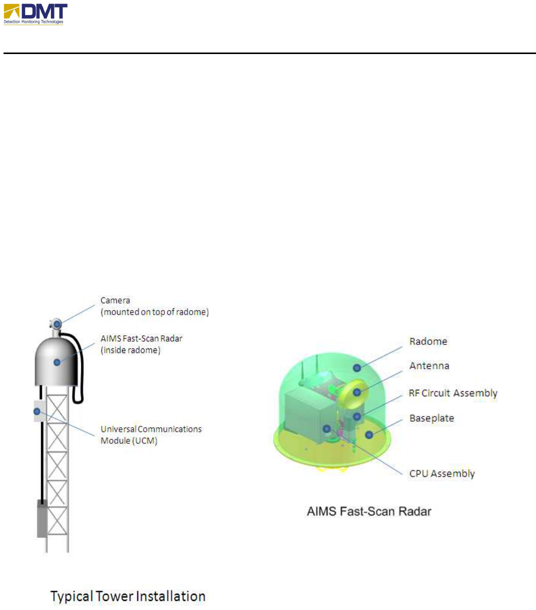
The AIMS Fast Scan is physically located where the monitored area of interest may be seen by
line-of-sight (unobstructed path). This is normally on an elevated position such as a tower, pole
or on a building structure. The radar is protected from the environment (wind, rain, ice, etc.)
with a Nomex radome. Optionally, the top of the radome can be fitted with integral captive plate
to mount a camera assembly on. The radar is actually comprised of a CPU assembly, RF
assembly, antenna, and baseplate assembly. The radome bolts unto the baseplate.
AIMS Fast-Scan Radar v3.22 Installation and Operations Manual
DMT, LLC • DMT-M200-311 • 06/2009
2
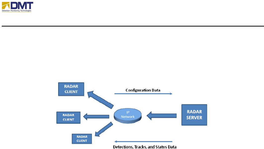
The AIMS Fast-Scan Server, which is the software application that runs in the CPU assembly,
communicates with one or more client software interfaces that provide the end user interface(s).
Minimal initial configuration is required at the Server; all other configuration changes should be
performed through the Client interface.
The AIMS Fast-Scan server is shipped in a variety of configurations, based upon the application
requirements, affecting the following;
• Transmit Power
• Operating Frequency
• Antenna
• Physical Packaging
• Value-Added Enhancements
AIMS Fast-Scan Radar v3.22 Installation and Operations Manual
DMT, LLC • DMT-M200-311 • 06/2009
3
1.1 Radar Configurations
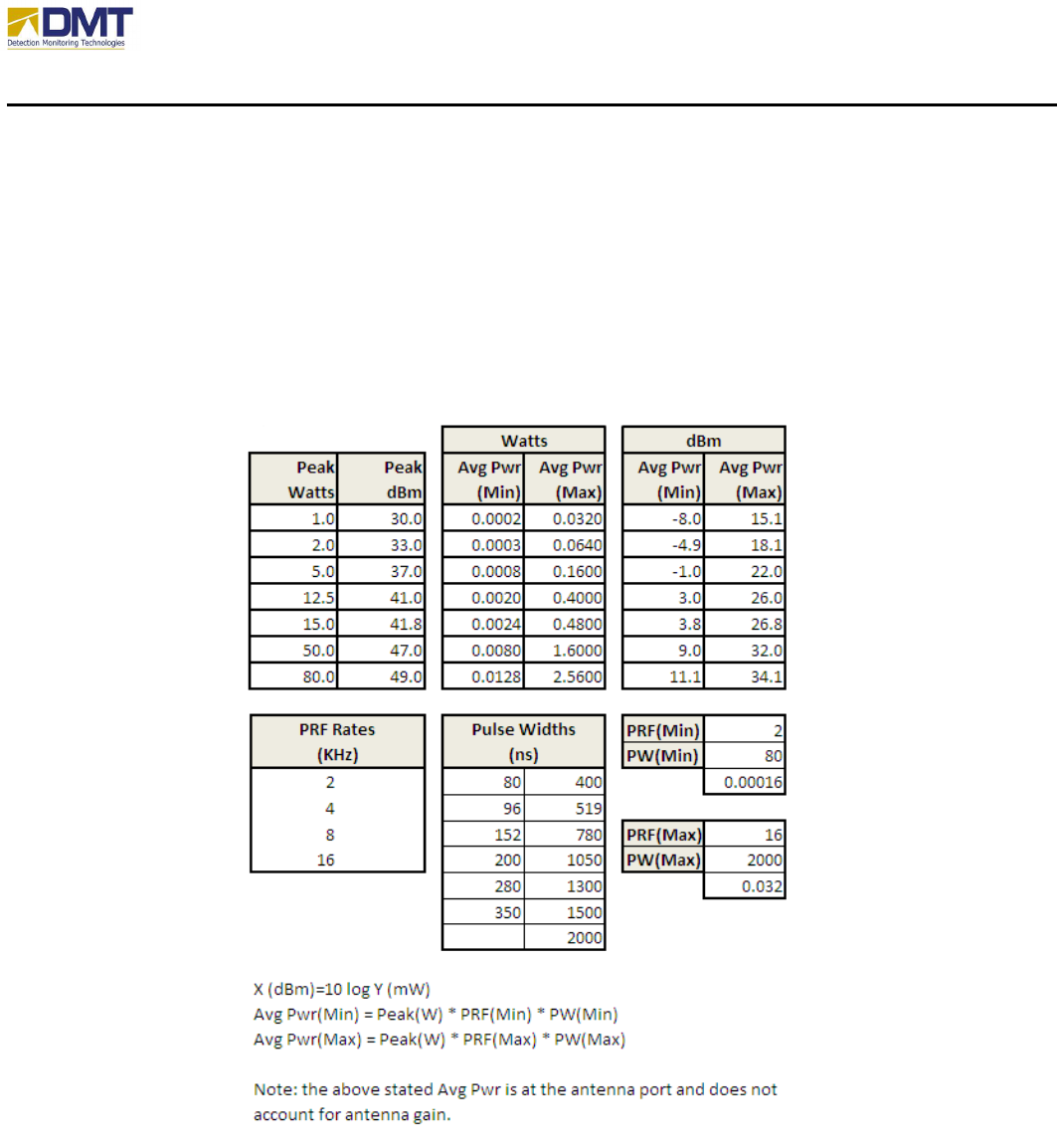
1.1.1 Transmit Power
The AIMS Fast-Scan is available in a number of different transmit power levels, determined by
the range of expected operation. At current, DMT offers the following transmit output power
configurations;
Obviously, the higher transmit power configurations require additional supply current, this is
discussed further in the “Connecting Power” subsection.

AIMS Fast-Scan Radar v3.22 Installation and Operations Manual
DMT, LLC • DMT-M200-311 • 06/2009
4
1.1.2 Operating Frequency
The AIMS Fast-Scan system operates in the X-Band (7-12.5GHz) frequency spectrum, centered
at 9.25GHz.
1.1.3 Physical Packaging
In most cases, the AIMS Fast-Scan system is packaged as shown below;
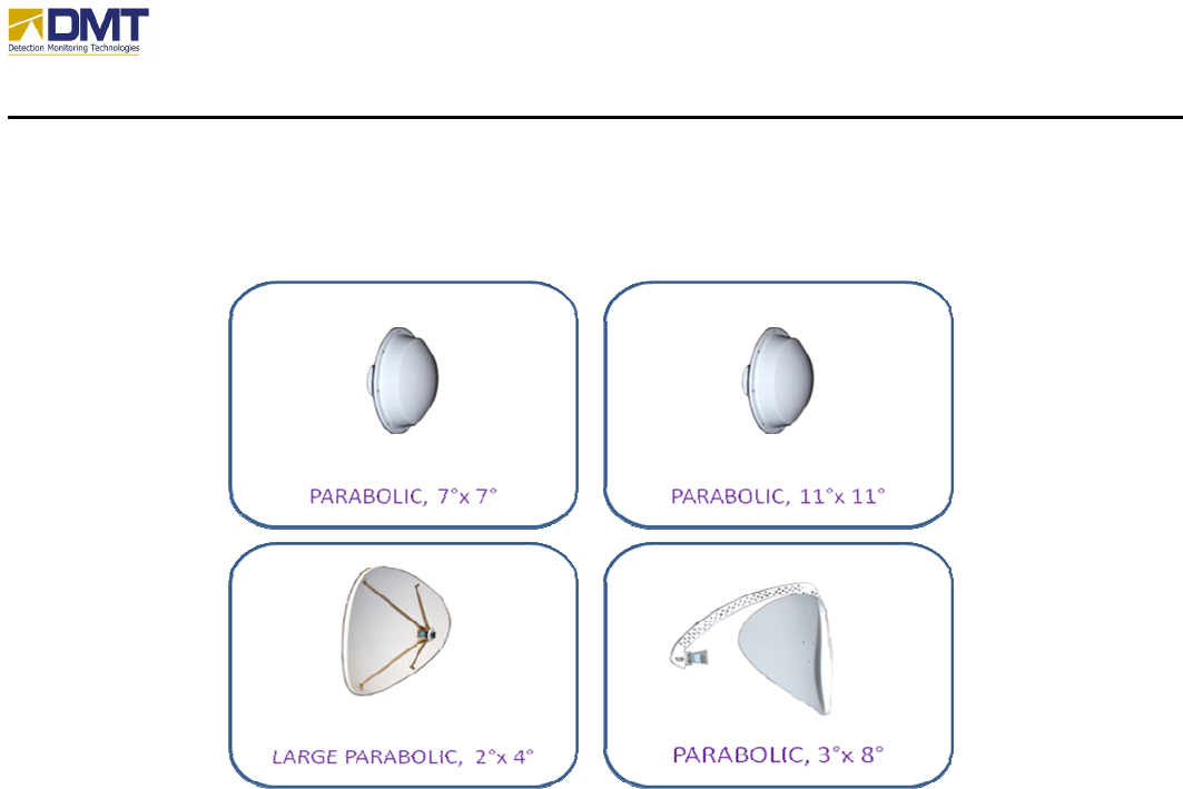
1.2 Antennae
A wide variety of antenna designs are currently deployed and in use with the AIMS Fast Scan
system. Antenna selection is based upon desired gain, beam width (vertical and horizontal),
polarization (for detecting persons a vertical polarization is recommended), size and weight. The
standard antennae currently in use include;
• Parabolic, 11°x11°
• Parabolic, 7°x7°
• Parabolic, 3°x8°
AIMS Fast-Scan Radar v3.22 Installation and Operations Manual
DMT, LLC • DMT-M200-311 • 06/2009
5
• Large Parabolic, 2°x4° (28” x 43”)
These are listed in an increasing detection range order. Others are available.
The selected antenna and expected range of elevation angle determines the radome and baseplate
that may be used. For instance, in a mobile application a minimal elevation angle might be
acceptable so that a low profile radome may be used.
The longer the range, the larger the antenna will be in the horizontal dimension. Since the
antenna is bigger, the baseplate and the radome will grow as well. The antenna for the long
range AIMS either an elliptical or rectangular dish or a planar array antenna. The antenna fastens
by 4 bolts to the antenna bracket and a 5/16-inch SMA wrench is used to fasten the RF cable to
the antenna.
The polarization of the parabolic antennae can be changed by rotating the feed horn by removing
4 allen-head screws, spinning the feed ¼ turn and reattaching in new holes. The antenna is
normally shipped and installed with a vertical polarization, optimized for detecting upright
objects such as persons.
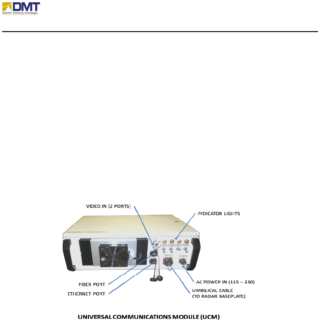
1.3 AIMS Universal Communication Module
The AIMS Universal Communications Module (UCM) was introduced in 2006, developed as a
standardized hardware interface shipped with each radar system. The Module is a NEMA 4X/6
enclosure with watertight connectors with the following features:
AIMS Fast-Scan Radar v3.22 Installation and Operations Manual
DMT, LLC • DMT-M200-311 • 06/2009
6
• Solid state power distribution (-40 to +90 deg C)
o Supply 1: 24VDC/7.5A for cameras
o Supply 2: 24VDC/20.8A for Peltier cooling in UCM and on radar baseplate
o Supply 3: 48VDC/7.3A for radar
o Supply 4: 12VDC/12.5A for local electronics in UCM
• Autosensing AC Power Input (115-230 VAC, 47-63 Hz)
• (2) Hardened single channel video servers (order must specify 1 to 4 servers)
• (1) Ethernet routers/switches
o (6) RJ-45 Ethernet ports (2 unused)
• Peltier cooling system (solid-state cooling with no outside air exchange) for 100 watts of
cooling – has temperature sensor (-40 to +85 deg C).
• Optional
o 24 VAC supply for dome cameras (-40 to +85 deg C)
o (2) Multi-mode fiber ports on Ethernet Switch (single mode also available)
The UCM comes with all connectors that can only fit one way on the radar and module. The
installation is simple and requires no special equipment. Shown below is a photo of a portable
version of the universal module.
1.4 Other Value-Added Enhancements
On request, DMT has performed a number of special value-added enhancements to the AIMS
Fast-Scan system. Many of these have recurred so frequently we have added them to our
product line;
• Video
• Video Codec (Moxa, AxSys). Mounted inside the UCM.

AIMS Fast-Scan Radar v3.22 Installation and Operations Manual
DMT, LLC • DMT-M200-311 • 06/2009
7
• Communication Adapters
• Ethernet to RS232/RS422/RS485 Adaptors (in UCM)
• Radar Mounting
• Tower Mounts (Rohn 45G/25G)
• Pole Mounts (4”, 8” and telephone pole)
• Wall Mounts
• Tripod Mounts
• Vehicle Mounts
• Shipboard Mounts
• Utility Enclosures
• Camera Mounts
• Positioning
• Global Positioning System (GPS)
• Electronic Compass
AIMS Fast-Scan Radar v3.22 Installation and Operations Manual
DMT, LLC • DMT-M200-311 • 06/2009
1
2 Reference
2.1 Documents
2.2 Acronyms and Definitions
The following acronyms and definitions pertain to the terminologies as they are used to define,
configure, describe or explain the AIMS Fast-Scan Radar.
Document Number / Date
Title
01/23/2008 Camera Alignment and Operation Procedures for AIMS EA-System
07/29/2008 AIMS Radar Program Replay Operation
07/08/2008 AIMS Antenna Elevation Controls
10/12/2007 AIMS Client Manual V3.0
Instr_XferMotorCodes
Acronym / Term
Definition
Comment
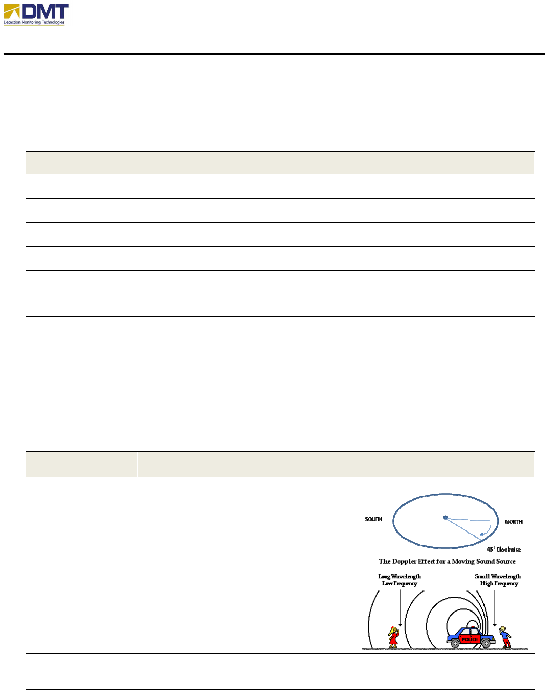
AIMS Area Intrusion Monitoring System
Azimuth Angle from reference bearing (i.e. true north)
in the horizontal plane. The example shows
an azimuth of 45 degrees (clockwise) from
true north.
Doppler The frequency shift of a signal caused from
its reflection off of a moving object. It can
also occur if the radar or source is moving as
well.
Elevation The angle from the horizon plane, where 0
degrees represents the horizon, a positive
elevation is aiming above the horizon, and a

AIMS Fast-Scan Radar v3.22 Installation and Operations Manual
DMT, LLC • DMT-M200-311 • 06/2009
2
negative elevation is aiming below the
horizon.
Range bin Area where detected targets are grouped
into
Radar
radio detection and ranging
AIMS Fast-Scan Radar v3.22 Installation and Operations Manual
DMT, LLC • DMT-M200-311 • 06/2009
3
3 Installation
3.1 General Guidelines
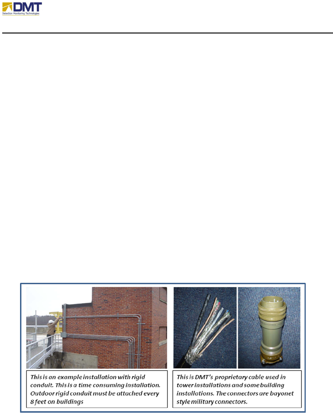
3.1.1 Cabling
Installations will consist of two kinds of cabling – DMT proprietary cables or standard cable
bundles in conduit. DMT proprietary cable is the quickest and easiest to install. The cable comes
with:
• 2 Ethernet bundles (one may be used for RS-232/422/485)
• 2 power sets (3 wires), which are shielded
• 2 video lines
• 1 inner strength member
• Outer shield.
The cable is designed to endure in saltwater, sun and high heat, sandy and oil environments.
The connectors are high-grade industrial bayonet metal connects. These are ordered to the
desired length, which is normally <= 150 feet. The cable and connectors are shown below right.
Building codes in some locations requires conduit runs if the cable is run any significant lengths
on buildings. Rigid conduit is required in these cases. The figure on the lower left shows an
outdoor installation requiring rigid conduit.

AIMS Fast-Scan Radar v3.22 Installation and Operations Manual
DMT, LLC • DMT-M200-311 • 06/2009
4
3.1.2 Power Cabling
When hooking up power cabling, the length of run and expected power consumption should be
considered. With these two factors, it is easy to determine what gauge of wire would generate
what amount of voltage drop. A 6% voltage drop is the recommended limit according of
industry standards (CEC).
V
drop
= distance * current * ohms/1000’ (see table below) / 1000
AWG Copper Wire Table
AWG
Diam. (mils)
Ohms/1000ft
Feet per Pound
0000
460 0.050 1.56
000
410 0.063 1.96
00
365 0.077 2.4826
0
324.85 0.096 3.1305
1
289.3 0.1264 3.947
2
257.6 0.1593 4.977
4
204.3 0.2533 7.914
6
162 0.4028 12.58
8
128.5 0.6405 20.01
10
101.9 1.018 31.82
12
80.8 1.619 50.59
14
64.1 2.575 80.44
16
50.8 4.094 127.9
18
40.3 6.510 203.4
20
32.0 10.35 323.4
22
25.3 16.46 514.12
24
20.1 26.17 817.7
3.1.3 Communications
The Ethernet communication lines from the UCM should not be run further than 90m, and
should only be made from parts/cabling rated to meet or exceed CAT5e or CAT6. The bulkhead
Ethernet connectors on the UCM are rated to meet IP67 specifications when attached to an IP67
cable. Although weather resistant, the orientation of the UCM installation should result in the
AIMS Fast-Scan Radar v3.22 Installation and Operations Manual
DMT, LLC • DMT-M200-311 • 06/2009
5
Ethernet connectors being either vertical (on side panel) or downwards facing to prevent the
pooling of water on the connector.
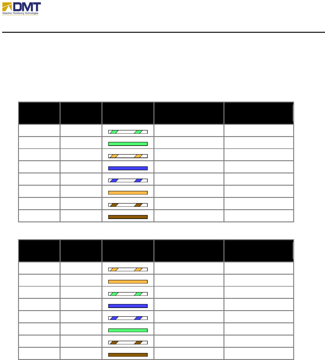
When using standard CAT5e/CAT6 wiring, adhering to the color standard will make the site
much more maintainable. Both the T568A (US Govt. std.) and T568B (AT&T std.) color tables
are shown below.
RJ45 Pin #
Wire Color
(T568A)
Wire Diagram
(T568A)
10Base
-
T Signal
100Base-TX Signal
1000Base-T Signal
1 White/Green
Transmit+ BI_DA+
2 Green
Transmit- BI_DA-
3 White/Orange
Receive+ BI_DB+
4 Blue
Unused BI_DC+
5 White/Blue
Unused BI_DC-
6 Orange
Receive- BI_DB-
7 White/Brown
Unused BI_DD+
8 Brown
Unused BI_DD-
RJ45 Pin #
Wire Color
(T568B)
Wire Diagram
(T568B)
10Base
-
T Signal
100Base-TX Signal
1000Base-T Signal
1 White/Orange
Transmit+ BI_DA+
2 Orange
Transmit- BI_DA-
3 White/Green
Receive+ BI_DB+
4 Blue
Unused BI_DC+
5 White/Blue
Unused BI_DC-
6 Green
Receive- BI_DB-
7 White/Brown
Unused BI_DD+
8 Brown
Unused BI_DD-
On some units, fiber optic network communications are available.
AIMS Fast-Scan Radar v3.22 Installation and Operations Manual
DMT, LLC • DMT-M200-311 • 06/2009
6
3.1.4 Selecting a Location
When selecting the radar site location a couple of key points should be considered;
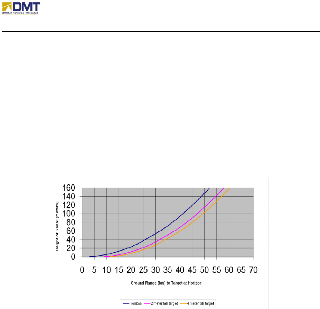
• The radar unit should have line-of-sight to area of interest. If you can’t see your intended
area of coverage, neither will the radar! Keep in mind that there is a maximum range
based upon the height of the radar unit and the curvature of the earth (see chart below).
• The radar unit should be mounted in a location that minimizes the opportunity for
vandalism. The installation of the radar attracts the curious. The power and camera
cables are twist bayonet-style cables that can be removed if accessible. The radar is
usually mounted on a tower or roof structure away from normal pedestrian traffic.
• Mount the radar unto a structure that is designed to support the expected wind load. The
standard DMT radome has a wind sail area of approximately 10 square meters. Less
rigid structures will allow the wind to incur harmonic oscillations unto the structure.
3.1.5 Installation on Towers, Buildings, or Poles
Installations are most common on towers, buildings and poles. Although DMT makes a variety
of standard mounts, custom brackets for other mounting surfaces or towers can be supplied in
usually 3 weeks from order. Typically building mounts are on top of the building. In these cases,
the installation is much the same as a on a tower. A small section of tower or similar is used for
maximum stability in high winds.
AIMS Fast-Scan Radar v3.22 Installation and Operations Manual
DMT, LLC • DMT-M200-311 • 06/2009
7
Rohn Towers is an industry standard in towers.
Although the company is no longer in operation,
their towers are still sold worldwide and there
have been widespread copies of the towers still in
production by a number of companies. DMT can
provide quick delivery of 25G, 45G and 65G
tower mounting brackets. The top of a tower
should be a standard 10 foot section, with the top
rungs removed so that the radar can slip down
over the top. ¼ -inch holes should be cut though
the main three beams of the tower and bolts run
through to permit firm attachment to the tower.
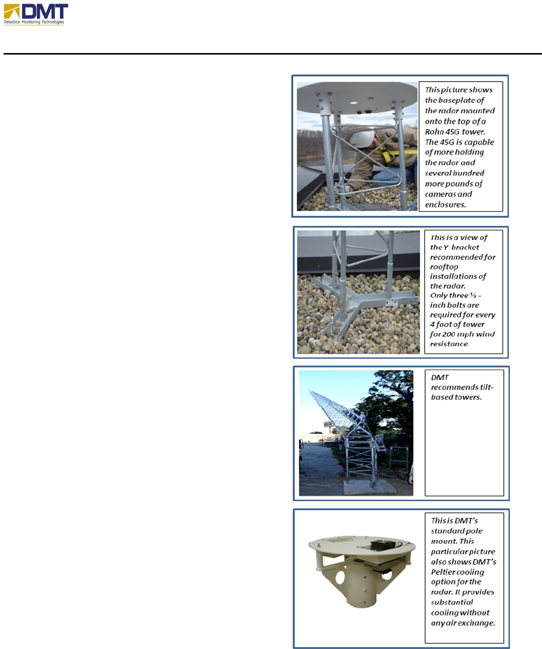
When placing this on buildings, DMT
recommends the Y-bracket. The bracket has 3
holes in each branch of the “Y” for attaching to the
roof. The picture at right shows a view of the
bracket installed. DMT recommends no more than
8 feet of tower for building rooftops. Grounding
(lightning) rods should be higher than the radar.
For ground installations, DMT recommends using
tilt-based towers. These come in hand-crank and
motorized lowering configurations. Figure 9 is a
photo showing the tower. These towers can be
erected by 2 people without the need of lifts or
cranes. It also enables easier maintenance of
sensors in the future.
Pole mounting should be on poles that are a
minimum of 4 inches in diameter for short heights
and 8 inches for poles over 2 meters high. The
figure at right shows DMT’s mounts for standard
power poles. It is important to mount the
baseplate on the towers or poles so that it is as
level as possible. This will simplify setup.
Although being perfectly level is desirable,
remember that the radar can correct for installation
flaws by moving the antenna in elevation as it
spins. It is required that an inclinometer be used to
measure the tilt error if it exists and record it for
software setup.
AIMS Fast-Scan Radar v3.22 Installation and Operations Manual
DMT, LLC • DMT-M200-311 • 06/2009
8
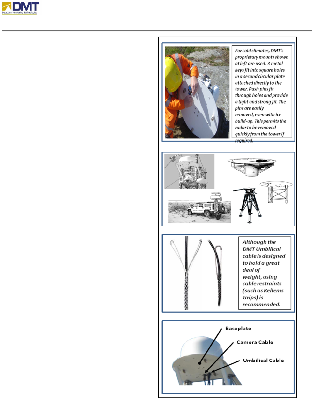
Over many installations, DMT has found
instances where different brackets or mounting
options are needed. In cold weather
environments, DMT had found that mounting
on towers became difficult due to ice build-up.
The radome has 12 bolts that hold it down and
the base plate is held in place with 8 more
bolts. In cold weather, ice can make threading
and handling bolts difficult. So DMT
developed a key and pin method for fastening
the radar to towers as shown in the figure at
right. This resulted in big reductions in
installation costs.
Generally, the radar can be mounted a number
of different ways;
• Pipe Mount (8” OD Schedule 80)
• Tower Top Mount (Rohn 45)
• Tower Side Mount
• Vehicle Mount
• Tripod Mount (temporary)
The main issue is to provide unobstructed
visibility to the area of interest, insure that the
cables may freely access the baseplate, and the
mounted solution has minimal vibration. The
cables that connect to the radar system attach to
the underside of the circular baseplate.
The umbilical cable that goes between the radar
baseplate and the Universal Communications
Module (UCM) should have a minimum bend
radius of 8”. The umbilical cable is made with
a ruggedized protective jacket and should be
restrained at the top with a cable grip (i.e.
Kellems grip – see drawing).
Located next to the umbilical connector on the
baseplate is the camera connector. Based upon
where the camera is located (top of radome or
on side mount), be sure the cable may be
properly dressed and secured for ice, snow, and
high wind.

AIMS Fast-Scan Radar v3.22 Installation and Operations Manual
DMT, LLC • DMT-M200-311 • 06/2009
9
3.2 Preparation
3.2.1 Before You Begin
• Ensure all Communications cables have been run and certified to Cat6. There should be 4
“straight” cables, with RJ-45 Connectors on both ends. One set of 4 connectors should be
at location where the Communications Module is to be installed.
• Ensure 220VAC or 120 VAC is available at location where the Communications Module
is to be installed.
• Identify locations of all other hardware to be installed, this includes: AIMS
Communications Module, AIMS Radar and Baseplate, Camera Assembly #1 through
Camera #N, and AIMS Junction Box,.
3.2.2 Tools
Installations can be quite varied from site to site. The tool compliment may vary some between
these sites. DMT recommends the following tool set:
• 5/32" Allen Wrench
• 3/16" Allen Wrench
• 7/32" Allen Wrench
• 1/4" Allen Wrench (Recommend an Allen pack containing sizes .050" through
3/8")
• 7/16" Combination Wrench Or Socket with ratchet 1/2" Combination Wrench Or
Socket with ratchet (Recommend combination wrench set containing sizes 1/4"
through 3/4" and an additional 11/32")
• Adjustable wrenches (spanners) – one 6-inch, one 8-inch, one 10-inch
• Ratching reversible wrench set (5/16 to 3/4 inch)
• One flat-head (medium size) and one Philips-head (medium size) screwdrivers
• one small flat-head jewelers or electricians screwdriver (used for terminal blocks)
• One set of wire cutters
• small flashlight
• One volt meter with autoranging functions
• Pasternack SMA Torque Wrench (5/16 inch) (Model No: PE5011-1, phone 949-
261-1920, Fax 949-261-7451, email: sales@pasternack.com.)
There will be instances where additional hardware, glues or epoxy will be required. Contact
DMT technical support for recommendations whenever in doubt.

AIMS Fast-Scan Radar v3.22 Installation and Operations Manual
DMT, LLC • DMT-M200-311 • 06/2009
10
Other DMT tools are available to simplify installation, failure indication or final certifications.
These include:
• DMT radar and home pin alignment tool (see Figure23) – Part Number: AIMS-
Tool-0110
• DMT umbilical cable checker/certifier (see Figure 25) – Part Number: AIMS-
Tool-0102
• SMA connector (5/16-inch) torque wrench – Part Number: AIMSTool-0101
• Automated Radar Evaluation and Setup Tool – Part Number: AIMSTool-0111
• Automated Setup Software Toolkit – Part Number: AIMS-Sftwr-ASST
The Automated Radar Evaluation and Setup Tool is a tool introduced in 2007. This tool is a
software package that resides on the thumb drive (memory stick). Upon powering the radar on,
insert the memory stick in one of 4 USB ports in the Electronics module (cabinet). The onboard
software on the stick will check that operating system is enabled and all the latest drivers are
installed. It also records all serial numbers and installed software and records the date in time in
which the stick was inserted into the radar. The software will also run checks on the motors,
communication ports, A/D board, CPU board, and in some units is will check onboard
temperature. During this process, the radar will spin so be sure it is ready to do so when the
memory stick is plugged in. When returning back to the office, the technician can insert this
memory stick in a computer and record all pertinent facts automatically into an Excel
spreadsheet record log.
The Automated Setup Software Toolkit is a BITE (built-in-test and evaluation) software package
the runs on a notebook PC or PDA. It has all the functions of the Automated Radar Evaluation
and Setup Tool, but provides more information in an easy to read visual format. The data is
stored in a resident Excel spreadsheet file.
3.2.3 Arrival of Equipment
Anticipate the delivery and transportation of the radar and equipment from the arrival point to
the tower so that you can obtain the proper size of vehicle needed. For a typical one-tower
installation, the radar will arrive in the following containers:
• (1) Radar crate (if not installed with radome)
o 80 lbs (37 kg)
o 21” x 26” x 27” (53.3 x 58.4 x 17.8 cm)
• (1) UCM, cables and hardware crate
o 174 lbs (79 kg)
o 41” x 29” x 25” (104 x 74 x 64 cm)
• 1 camera case (if ordered) – this will be labeled “CAMERA”. (size / weight are variant)
• (1) Radome crate
• Jumbo (long range system):
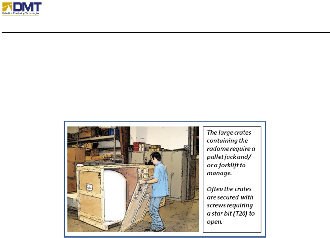
AIMS Fast-Scan Radar v3.22 Installation and Operations Manual
DMT, LLC • DMT-M200-311 • 06/2009
11
63” x 63” x 51” (160 x 160 x 129.5 cm)
690 lbs (314 kg) – with radar installed (40 lbs or
• Standard (medium Range):
41" x 44" x 44" (104 x 112 x 112 cm)
376 lbs (171 kg) – with radar
• Other sizes are also available
AIMS Fast-Scan Radar v3.22 Installation and Operations Manual
DMT, LLC • DMT-M200-311 • 06/2009
12
3.3 Mounting the Radar
3.3.1 Installation Procedures for AIMS Fast-Scan
1. Power should be off and fully disconnected before installation commences
2. Mount all AIMS Hardware in the desired locations, using existing bolt hole patterns in
boxes.
• It is of vital importance that care be taken when Electronic Module (enclosure
containing CPU stack) box are open. Although the system is well grounded and
resistive to ESD, it is wise to avoid static charge before installing the radar.
• It is best to align the homing pin of the radar with true north, any deviation can be
entered in the configuration software.
• Any holes remaining on the baseplate that are not used should be plugged with a bolt,
nut and lockwasher.
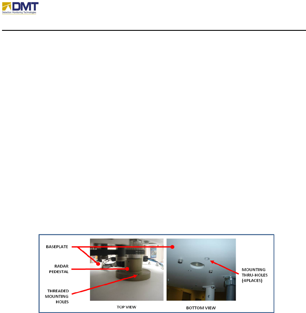
3. If required, mount the radar onto the base plate. There are 4 holes surrounding a big
center hole on the base plate. The radar is attached to the base plate using four 1-inch
socket head bolts provided. These bolts feed through the bottom of the base plate up into
the threaded radar pedestal.
4. For radars shipped in white ISO containers, the elevation motor control cable may be
unplugged. This cable feed out of the top of one of the radar enclosures and has
connector. Plug this into the black elevation motor and tighten the screws.
5. Run all AIMS Cables. Prior to pulling any AIMS cable through conduit ensure the
desired cable end will be at the correct location. All the cable connectors and their mating
jacks are labeled. The Interconnect Diagram is provided separately.
AIMS Fast-Scan Radar v3.22 Installation and Operations Manual
DMT, LLC • DMT-M200-311 • 06/2009
13
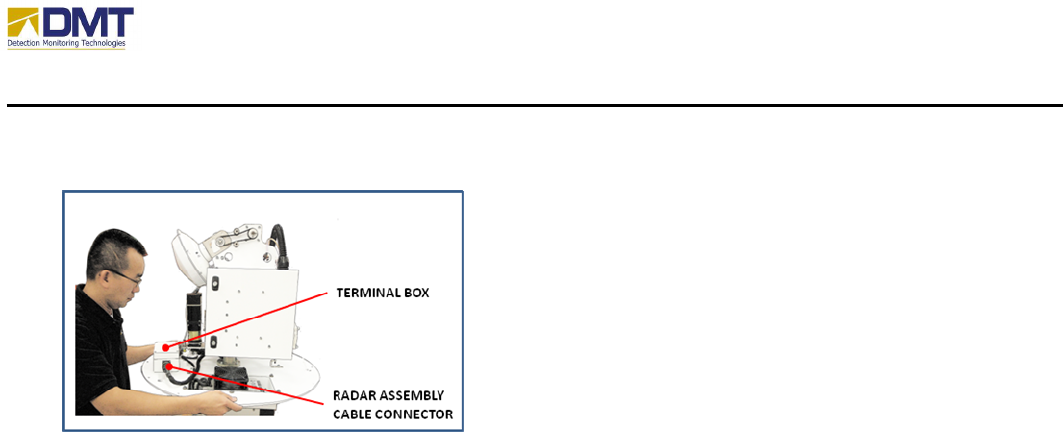
6. When installing the base plate, the white terminal box should go right side up, so that it is
inside the radome when it is sealed.
The white terminal box on the base plate sits up and
is inside the radome when it is installed. The white
box houses the wiring block. Power and
communications from the radar and the outside
world are connected in this box.
7. The radar assembly cable has a bayonet-style
connector that attaches to the right side of the
terminal box (see figure).
8. After all AIMS Cables are run through the conduits between the radar and cameras and
enclosure, you can mate the connectors. Do not attempt to apply power to any AIMS unit
without a DMT, LLC employee or certified installer present. Failure to comply with this
could result in equipment damage and may void warranty.
9. The radome is attached using the 12 longer socket-head bolts provided. Washers should
be on both the top of the radome and the bottom of the base plate. The radome lip will
compress very slightly when the bolts are tightened. This seals the radar from the outside
elements. Do not over tighten because this can result in cracking the radome finish. The
radome is made of NOMEX, which is a composite honeycomb structure that is strong
and lightweight.) The baseplate should be clean and free of debris as the radome is placed
on it. The radome lid should be clean prior to installation as well. DMT certified
installers must inspect inside the radome before power is applied to the radar. Therefore,
provisions need to be made to provide installers access to the radar when radar setup
commences.
3.4 Locating the UCM
The primary function of the UCM is to provide the power and communications to the AIMS Fast
Scan system. Power and communications are provided via a heavy-duty umbilical cable that
connects the two systems. The umbilical cable also supports two 75Ω video feeds from top
mounted cameras, if installed. Although the UCM is designed to operate outdoors an indoor
installation is always preferable.
Three major factors need to be considered when installing the UCM
• How long is the umbilical cable relative to the distance between the radar and UCM?
• How long is the UCM from the primary power source (line loss vs. wire gauge)?
• How much power is required (varies on configuration)?
AIMS Fast-Scan Radar v3.22 Installation and Operations Manual
DMT, LLC • DMT-M200-311 • 06/2009
14
If ordered for a pole mount configuration, the UCM is shipped with pole clamps and supporting
hardware. When installed, the interfacing connectors on the UCM should be facing downwards.
When mounted outside, the UCM cabling should be connected to an weatherproof electrical box
for conduit cable routing for protection from both the environment and rodent damage (mice and
rats are renown for their appetite of cable jacketing).
3.5 Camera Installation
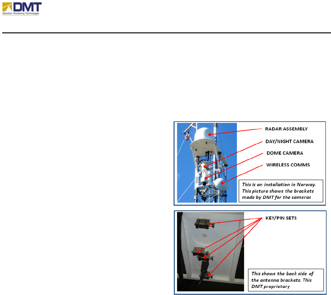
DMT makes camera brackets for many cameras
for most towers. The figure at right shows two
cameras on the tower. One camera is tied
directly to radar detections (the upper
thermal/CCTV camera) and the other camera
(the dome security camera) is used for tower
security. DMT makes brackets for both of these
cameras, for instance.
As discussed earlier, key and pin mechanisms
developed by DMT hold the cameras in place on
the tower. This DMT proprietary approach is
really of value in cold climates. The pins can be
removed easily by pressing a button at the
flanged end of the pin and then pull. In the
above installation these key and pin sets hold
both the cameras and the communications
antenna in place.
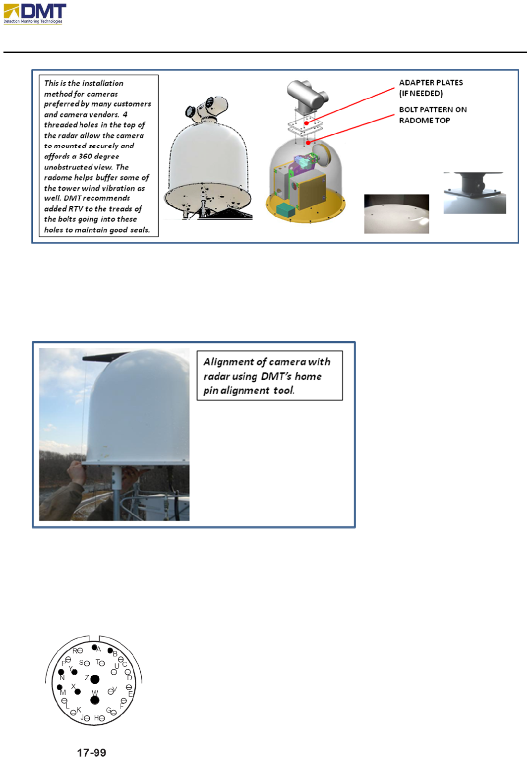
The cameras can also be mounted on the radome.
The figure below shows the mounting holes,
which fits the DI-5000 and Orion, Argon ST, Quickset Model 90 Pan and Tilts and many other
cameras.
AIMS Fast-Scan Radar v3.22 Installation and Operations Manual
DMT, LLC • DMT-M200-311 • 06/2009
15
It is important that the camera and radar home pins are aligned if the camera is mounted on top
of the radome. The figure below shows a tool available from DMT. The tool bolts into the 4-hole
pattern in the top of the radome. A plumb bob is then used to locate where the home pin should
be. Another tool fits in the large hole in the baseplate for marking the home location from below.
This picture shows the alignment process of the radar home pin to the camera home pin.
The DMT AIMS Fast-Scan system is designed to support a wide variety of cameras and pan-tilt
control assemblies. When an AIMS Fast Scan unit is ordered the camera type is also specified to
be sure that the connector cable between the camera and the radar baseplate is correctly
assembled and tested. Because the camera and its pan-tilt base connector requirements are so
varied, the cable pinouts are equally as diverse. A typical pin configuration for an ICx or DII
camera connector appears below.

AIMS Fast-Scan Radar v3.22 Installation and Operations Manual
DMT, LLC • DMT-M200-311 • 06/2009
16
Baseplate
Connector TVP00RW-17-99S
Pin Description
A +24VDC SUPPLY
B 24V COMMON
M RS422 TX+
N RS422 TX-
X RS422 RX+
Y RS422 RX-
W VIDEO IN2
Z VIDEO IN 1