DETECTION MONITORING TECHNOLOGIES AIMSFS-05X AIMS FAST SCAN RADAR SYSTEM (AIMSFS-05X) User Manual AIMS FS Radar I O Manual v1 0
DETECTION MONITORING TECHNOLOGIES, LLC (dba DMT, LLC) AIMS FAST SCAN RADAR SYSTEM (AIMSFS-05X) AIMS FS Radar I O Manual v1 0
Contents
Installation Guide 2

AIMS Fast-Scan Radar v3.22 Installation and Operations Manual
DMT, LLC • DMT-M200-311 • 06/2009
17
3.6 Connecting Power
3.6.1 Radar
AIMS Radar systems are all designed for 48 VDC input. Clients can optionally order 24 VDC
versions as well, but these must have a 24 volt universal communications module version
feeding it. AIMS radar systems are power conditioned, so they can be powered by four 12 volt
car or RV batteries. A volt meter and cut-off switch should be installed if running on batteries to
ensure the radar is not damaged from drooping voltage as the battery dies. The CPU will
shutdown if voltage droops significantly. If this occurs, communications to the client software
will discontinue and the radar will require cycling powering to restart the radar server software.
AIMS Fast-Scan radar systems come in a variety of ranges. For 1.5 km systems, the power pull
will be a consistent 2 AMP load, or 98 Watts when running. There is a rush pull of current
(spike) at startup, which can be high as 2.5 AMPS. Power draw and current rush increases for
further range systems. For 20 Watts, the power draw is about 150 watts (varies slightly with
options) with a 200 Watt rush at startup.
3.6.2 Cameras
Most thermal cameras use DC voltage. The range of voltage is 12 to 28 VDC for the most part.
DMT has 24 VDC supply for the purpose of feeding thermal cameras. A 12 or 15 VDC supply is
also included for powering onboard electronics. This can be routed to the wiring block for use by
the camera (see wiring block diagram for Universal Communications Module – Figure 14). The
power draw for many uncooled thermal cameras are less than 25 watts of power. Cooled thermal
cameras or multi-sensor camera products can pull considerable current. Check that the power
draw is less than 75% of the power rating on the 24 VDC power brick (printed on the brick).
Many dome security companies use 24 VAC. Optionally, the Universal Communications
Module can be fitted with a 24 VAC supply. This supply is rather large and should be able to
power any dome camera on the market that uses 24 VAC. Check the camera literature before
using this supply to ensure you have selected the right power. Some newer models of dome
cameras have switched to DC voltage, so damage can occur if the wrong selection of DC or AC
is made.
3.6.3 Universal Communications Module and Utility Enclosures
The Universal Communications Module (UCM) and the base tower utility enclosures accept 120
to 240 VAC, 40-63 Hz (auto-ranging). Power conditioning is present on every enclosure
provided by DMT, however, the power should be within 25% of the rated supply voltage.
AIMS Fast-Scan Radar v3.22 Installation and Operations Manual
DMT, LLC • DMT-M200-311 • 06/2009
18
Circuit breakers exist in all enclosures provided by DMT. These protect the radar, cameras and
other equipment from faulty hookups or power problems. These are a safety measure supplied by
DMT and are not a substitute for proper planning, preparation and care.
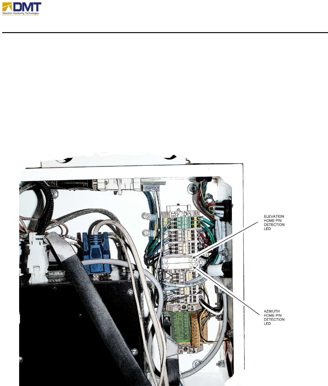
3.7 Hardware Adjustments
The antenna is controlled by two motors, an azimuth motor for bearing and an elevation motor
for elevation relative to the ground. Under normal circumstances, both of these should be
properly adjusted and require no modification. When set to the home position (0º azimuth, 0º
elevation) both of the home pin detection LEDs should be lit (see below). If not, these may
require adjustment detailed in the following two subsections.
AIMS Fast-Scan Radar v3.22 Installation and Operations Manual
DMT, LLC • DMT-M200-311 • 06/2009
19
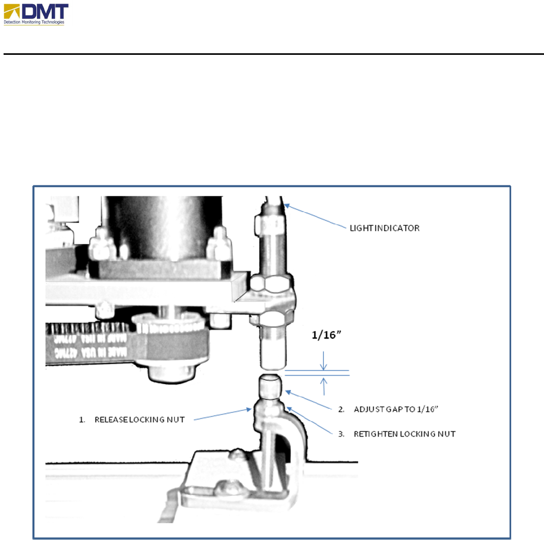
3.7.1 Adjusting the Azimuth Home Pin
The adjustment of the azimuth home pin positions the top of the home pin close enough for the
hall-effect sensor to detect it while far enough away to prevent accidental collision between the
detector and the home pin during use or transport. The adjustment is fairly simply and only
requires an adjustable open end wrench and hex key (see below).
While adjusting the azimuth home pin, remember that the radar will always spin to the right
(clockwise) when searching for the home pin.
AIMS Fast-Scan Radar v3.22 Installation and Operations Manual
DMT, LLC • DMT-M200-311 • 06/2009
20
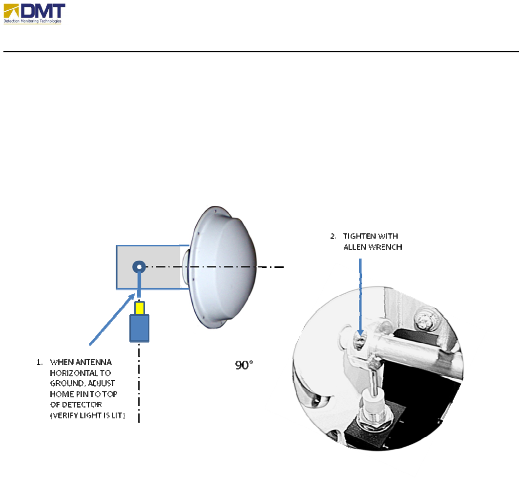
3.7.2 Adjusting the Elevation Home Pin
The adjustment of the elevation home pin positions the home pin directly over the hall-effect
sensor while the antenna is aimed parallel to the horizon. The adjustment is fairly simply and
only requires a hex key (see below).
When adjusting the elevation home pin, remember that the radar will always assume the antenna
is resting in a downward position and will elevate the antenna to search for the home position.

AIMS Fast-Scan Radar v3.22 Installation and Operations Manual
DMT, LLC • DMT-M200-311 • 08/2009
21
4 Server Software
Although most all of the software parameters may be modified through the server interface, it is
recommended that the normal use and modification of the system parameters be performed from
the client interface where more comprehensive error-checking and boundary conditioning is
performed to prevent the user from configuring an abnormal operating condition.
Nonetheless, in this section we will introduce the reader to the user screens available at the
server interface and will advise which parameters must be setup from the server interface.
4.1 Configurable Features
The table below provides a brief overview of the configurable parameters within the AIMS radar
server. Additional features are available from the client interface.
Waveform
Generation
Signa
l
Processing
Motion
Display / Save
Data
Other
BITE
PRF Rate A/D Sample Rate Mode
• Positional
• Velocity
Graphing GPS Check A/D Limits
Pulse Width Range Bins
• No of bins
• Zero range
Scripts Segment Trunc. Compass
No. of Pulses Filters
• Smoothing
• Matched
• Ramp
Limits
• Azimuth
• Elevation
Autosave Data Cameras
• Track to Alarm
• FOV
• Comm.
• Video Svr
• Offsets
Lobe Removal
• Main Lobe
• 2
nd
Lobe
• 3
rd
Lobe
Offsets Broadcast Interval Network
• IP Addr
• Port
Tracker
• AB Tracker
• Associator
Autoscan Save Settings
TX Frequency Tilt Compensation Restore
Zones Motion Compens. Replay
Sensitivity Start/Stop
Speed Threshold
Normalization
Basically, the configurable features entail;
• Defining the transmitted pulse (waveform generation)
• Selecting how to process the received signal (signal processing)
• Aiming the antenna (motion)
AIMS Fast-Scan Radar v3.22 Installation and Operations Manual
DMT, LLC • DMT-M200-311 • 08/2009
22
Additional configurable features include;
• Configuring geo-positional devices (GPS, compass)
• Integrating cameras
• Saving/replaying captured data
These configurable features are organized in an array of ‘tabs’ that provide user friendly check
boxes and option lists and are described in the following section, “Server Interface Screens”.
4.2 Server Interface Screens
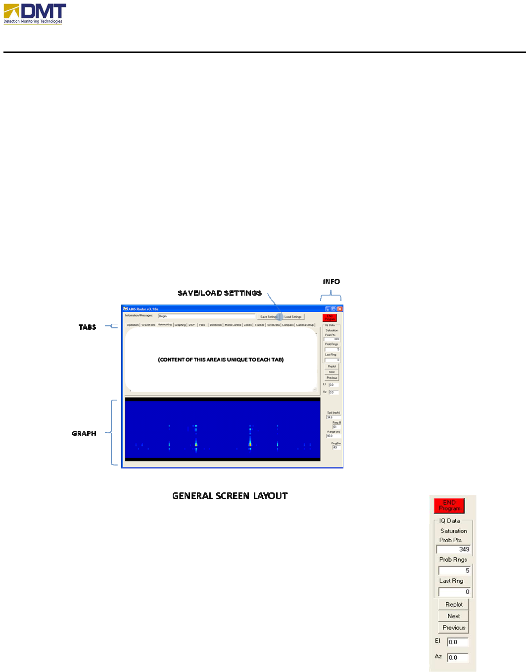
The basic server screen appears like (picture below):
The information sidebar on the right hand side of the screen provides general
information about antenna elevation and azimuth angles, saturated points (too
much signal), and details about where the mouse cursor is positioned (speed, freq
#, and range/rangebin) over the FFT Graph, when enabled.
The controls along the right edge of the main form are seldom used during
normal operation. “End Program” is used to stop the application when the radar
is operating (in the operation loop). Replot, Next, and Previous are used for
playing back stored data. Replot will prompt the user for data files to be
replayed. The files are now stored in the directory, “<r>:\data”. Next and
Previous allow the user to scroll forward and back through the list of files. When

AIMS Fast-Scan Radar v3.22 Installation and Operations Manual
DMT, LLC • DMT-M200-311 • 08/2009
23
files are selected to replay (Replot is clicked) the option to plot data is automatically selected.
The radar should always be in a stopped state before data is replayed. The El and Az text boxes
provide the present Elevation and Azimuth pointing angles for the radar.
The Graph area displays the currently selected graph mode (none, FFT, or line plot) and remains
visible regardless of which tab is currently selected.
The tabs provide access to the various features that may be changed to configure the system.
The tabs include;
• Operation
• Waveform
• Networking
• Graphing
• DSP
• Files
• Detection
• Motor Control
• Zones
• Tracker
• SaveData
• Compass
• Camera Setup
The following subsections briefly discuss each tab and its parameter settings.
AIMS Fast-Scan Radar v3.22 Installation and Operations Manual
DMT, LLC • DMT-M200-311 • 08/2009
24
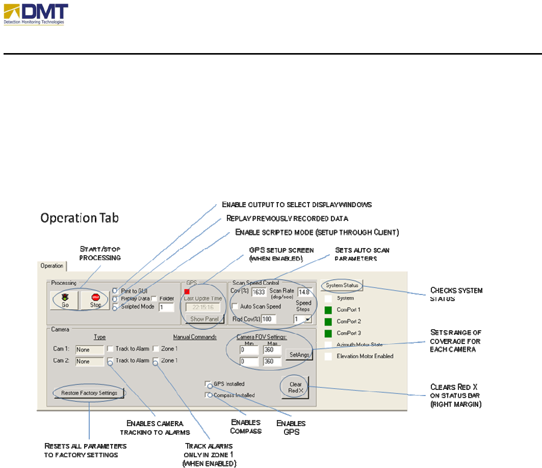
4.2.1 Operation Tab
Controls on the Operation tab are intended to be the most used controls once the application is
running. In addition to controls status lights let the user know if there are problems with the
communications ports, or motors.
4.2.1.1 Processing Parameters
The Go and Stop buttons are used to start and stop the radar. Clicking the Go button sets a flag
and puts the radar into the OperateLoop. Once entered the loop is continuous. Pressing the Stop
button sets another flag that prevents the Operate subroutine from being called. The Operate
loop is where the digitized data is processed.
Several check box options are available
• Print to GUI. The detection data is printed in the box on the Detection Tab.
• Replay Data/Folder. Prompts the user to select files for plotting. This is a diagnostic
mode and should only be selected when the radar is stopped. To change the list of
AIMS Fast-Scan Radar v3.22 Installation and Operations Manual
DMT, LLC • DMT-M200-311 • 08/2009
25
selected files the check box should be cleared and then checked again. To replay all files
in a folder, check the folder checkbox.
• Scripted Mode. Checking this box results in values for the min and max ranges and the
elevation angle being read from a file. The values stored are indexed by the azimuth
angle and are intended to allow the radar to follow an outline created for an area of
interest (configurable only through the Client interface).
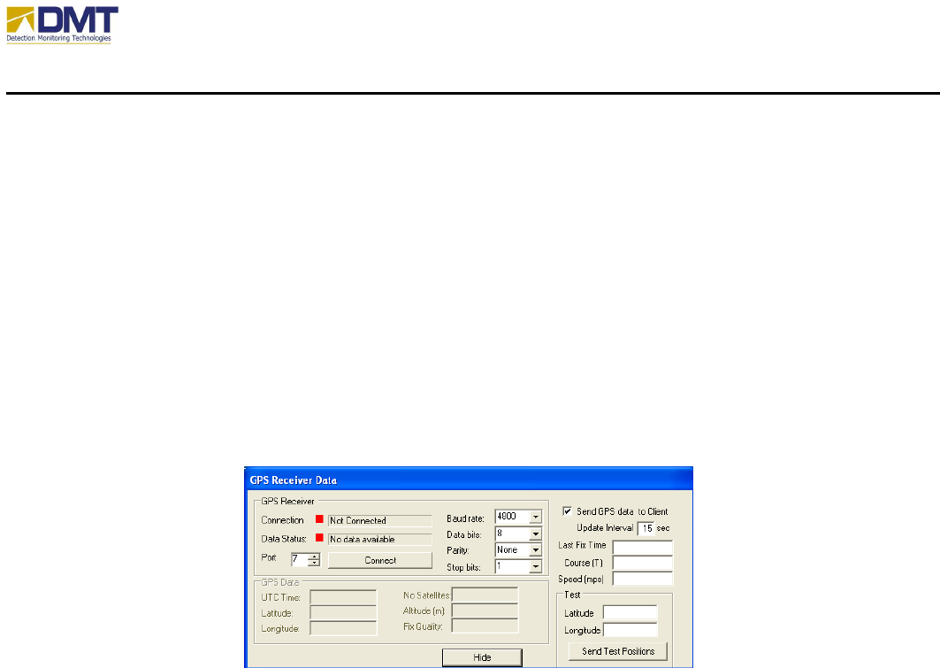
4.2.1.2 GPS Parameters
When “Show Panel” is selected, a new window is created allowing the user to configure the GPS
parameters and to check the status of the unit.
The GPS settings include;
• Communication Parameters
o Serial Port
o Baud Rate
o Data bits
o Parity
o Stop Bits
• Connect (attempts to communicate GPS device)
• Send GPS data to Client (allows the update of GPS data to connected clients)
• Update Interval
• Test (allows user to manually enter a geo-position for testing)
4.2.1.3 Auto Scan Control
Auto Scan is a learning algorithm that tries to set the optimum motor speed dynamically to insure
the desired overlap in azimuth beam positions. It evaluates the min and max ranges for each
angle and the processing speed to determine the best speed setting. It works best for very wide
sector scans and 360° rotation. The Auto Scan control parameters include;
AIMS Fast-Scan Radar v3.22 Installation and Operations Manual
DMT, LLC • DMT-M200-311 • 08/2009
26
• Enable/disable Auto Scan Speed
• Required Coverage% (1-100%)
• Speed Steps
Also displayed in this area are;
• Actual Coverage %
• Current Scan Rate (deg/sec).
4.2.1.4 Camera Parameters
For both Camera 1 and 2, the camera tracking settings include;
• Track to Alarm. Checking this box will enable slew-to-cue tracking of the camera to
alarm detections.
• Zone 1. If Track to Alarm has been checked, the checking of this box restricts the
tracking to alarms detected within Zone 1 only.
• Camera FOV Settings. The minimum and maximum field of view (FOV) settings are
used to limit camera tracking to range of coverage for each camera (after entering new
values in text boxes click SetAngs to load values in system).
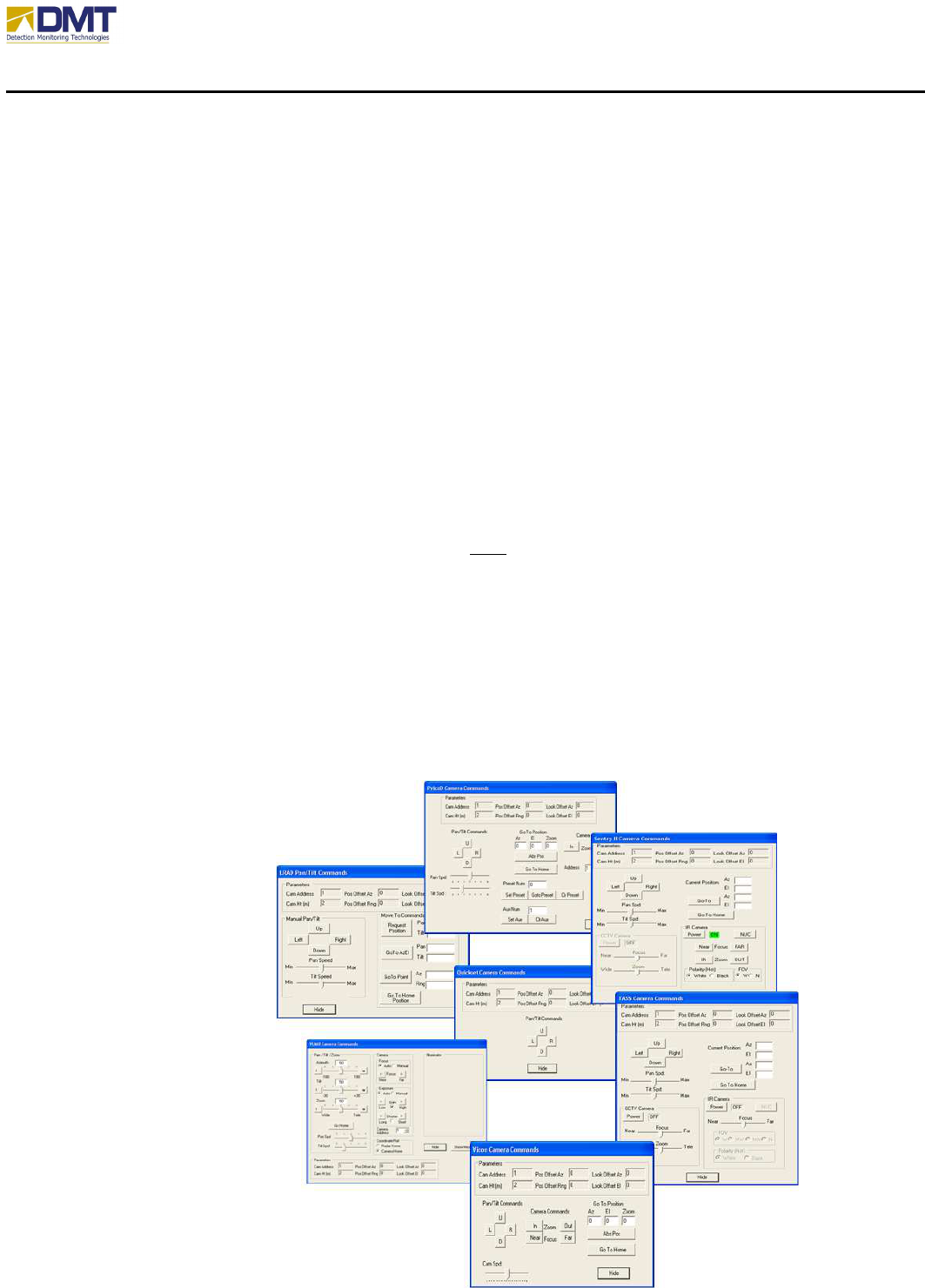
If a camera had been setup there would also appear another button Show Cmds immediately to
the right of the Zone1 checkbox. Selecting this feature brings up a new window containing
camera management tools uniquely setup for each camera Type (see Camera Setup tab). Some
example camera management screens appear below.
4.2.1.5 GPS/Compass
Installed
These two check boxes are
used to enable other
functions supporting the GPS
and Compass. When
selected, the
configuration tools for the
GPS (see GPS
Parameters, above) and
Compass (see Compass Tab)
are enabled for editing.
4.2.1.6 System Status

AIMS Fast-Scan Radar v3.22 Installation and Operations Manual
DMT, LLC • DMT-M200-311 • 08/2009
27
Selecting this button engages a built-in test function that verifies communications with the serial
communication ports 1, 2 and 3, interrogates both the azimuth and elevation motors and verifies
no other errors have been reported.
4.2.1.7 Restore Factory Settings
Used when all other efforts have failed to restore the operational state of the equipment! Before
the equipment has left the DMT factory, during the final testing process, a factory settings file is
created (“FactorySettings.txt”). Like the Saved Settings file (“SrvrSetMR.txt”), the Factory
Settings file is used to restore the equipment to a known operational state. Please do not alter
this file.
AIMS Fast-Scan Radar v3.22 Installation and Operations Manual
DMT, LLC • DMT-M200-311 • 08/2009
28
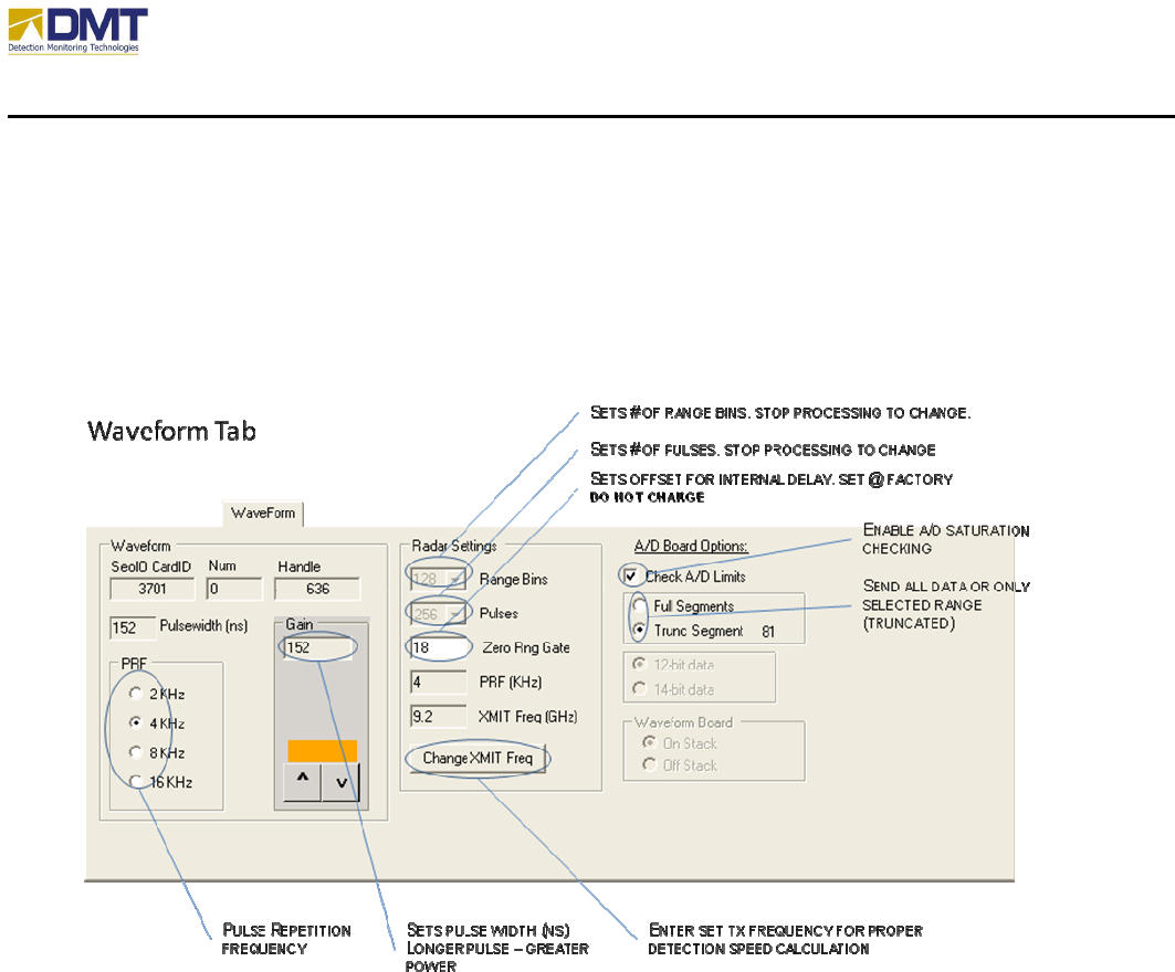
4.2.2 Waveform Tab
The Waveform Tab (see below) is used to set the basic radar waveform parameters, such as pulse
width, pulse repetition rate, zero range gate (0 offset), number of range bins and number of
pulses.
4.2.2.1 Waveform Settings
The waveform settings include;
• PRF. The pulse repetition frequency (PRF) sets the rate the pulses are generated. The
Pulse Repetition Frequency (PRF) controls the maximum unambiguous velocity interval.
It sets the maximum number of radar pulses (energy bursts) per second emitted by the
radar. Increasing the PRF increases this interval. The default setting of 4 KHz allows
targets traveling at speeds of ~+/‐33 m/s (72 mph) or slower to be resolved. Objects faster
than that speed will be detected, but their speeds will be reported incorrectly. The
Doppler resolution is affected by this setting as well. Example: 4 kHz PRF yields a
maximum unambiguous Doppler of 72 mph. If 256 pulses are used in the FFT (algorithm
used to calculate Doppler), then the smallest resolvable speed is 72/(256/2) = 0.56 mph.
If the number of pulses integrated is 1024, then the smallest resolvable speed is
72/(1024/2) = 0.14 mph
AIMS Fast-Scan Radar v3.22 Installation and Operations Manual
DMT, LLC • DMT-M200-311 • 08/2009
29
• Gain. The gain control value changes the amount of energy radiated by increasing the
pulse width in nanoseconds.
Also displayed in the area are;
• SeaIOCardID.
• Num
• Handle
These values are returned by the radar’s digital I/O board on initialization. If the values
displayed in these boxes are not simple integers, the A/D board may not be properly setup
(consult DMT for technical assistance).
4.2.2.2 Radar Settings
The radar settings include;
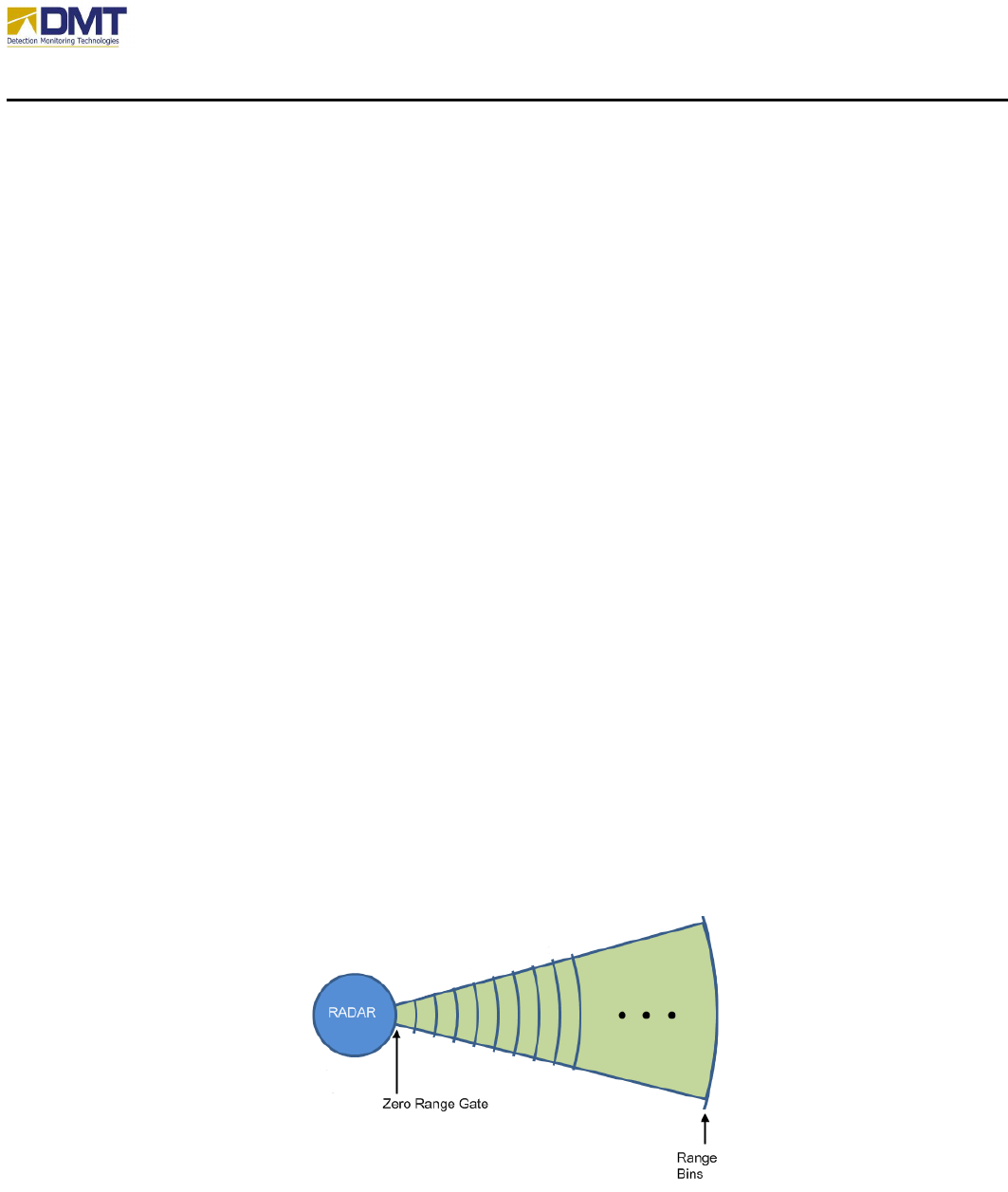
• Range Bins. Defines the total number of range bins to be processed (including zero range
gate) on each dwell.
• Pulses. Defines the number of pulses to be transmitted on each dwell.
• Zero Range Gate. The “zero range gate” defines the internal delay (in ‘bins’) before the
transmitted pulse actually leaves the antenna. This is a factory-set parameter and should
not be changed. This value is normally set between 15 and 20.
• XMIT Frequency. This entry is set to the center frequency configuration of the system so
the graphing function correctly displays the Doppler information (use Change XMIT
Freq to set). Note: It is important that this number is properly set. It is used in the
calculation of the detected speed of an intruder.

AIMS Fast-Scan Radar v3.22 Installation and Operations Manual
DMT, LLC • DMT-M200-311 • 08/2009
30
The Doppler Resolution is expressed by the number of pulses integrated by the radar in a given
look direction (azimuth angle). It also sets the number of pulses used by DMT’s FFT (Fast
Fourier Transform) algorithm (discussed in the Processing Section of this document). The
default setting is 256 pulses and is incremented in powers of 2 (i.e., 2n) steps. Increasing the
number of pulses increases integration time on objects in the radar beam, which results in
stronger return strength. Therefore, increasing the number of pulses will increase range
performance. Longer integration time (increasing the number of pulses) also lengthens the
processing time. As processing time increases, scan rates must be reduced to prevent voids in
coverage. It also takes longer to receive larger numbers of pulses. For instance, it takes 0.0.64
seconds to collect 256 pulses at a PRF setting of 4 kHz. It takes 0.256 seconds to collect 1024
pulses at the same PRF rate. This factor of 4 increase in collection time means the radar must
spin by a factor of 4 slower to keep the radar beam on the object for the entire integration
sequence. So scan rates should be lowered considerably for scan rates of 1024 and higher. The
Dop Resolution control gets its names because the number of pulses also determines the Doppler
resolution. The larger the number of pulses, the finer the increments of Doppler measured. An
example of Doppler resolution is covered in the description of the PRF control.
4.2.2.3 A/D Board Options
The A/D Board options include;
• Check A/D Limits. This enables the error checking of the A/D board configured state.
• Segments Sent. As the received signal data segments are processed they are sent from the
server to the connected client interfaces. If truncated segments is selected, only those
segments that are within the min/max range bins settings (Graphing Tab) are sent. This is
useful to minimize data bandwidth and speed, but should not be used if collecting/saving
data.
AIMS Fast-Scan Radar v3.22 Installation and Operations Manual
DMT, LLC • DMT-M200-311 • 08/2009
31
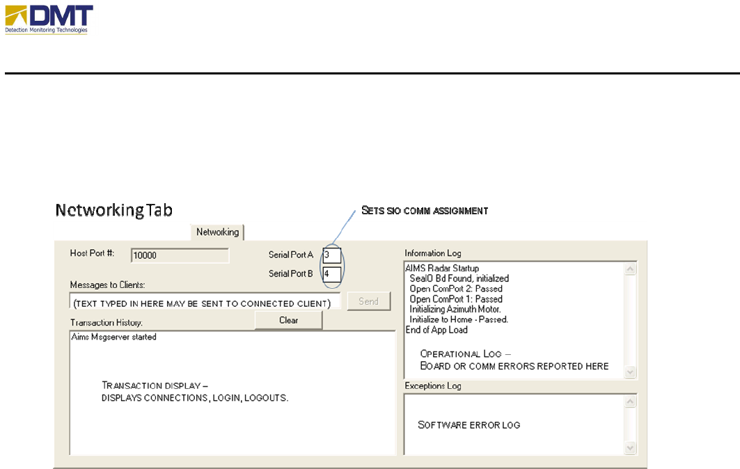
4.2.3 Networking Tab
For the most part, this is an informational tab that may be used to check the operational status of
the equipment. There are only two settable features here, the communications port assignment
for Serial Ports A and B (default ports for Camera 1 and Camera 2, respectfully)..
A single line message may be sent from the Server site to a connected Client by using the
“Messages to Clients” text box (click “Send” after entering message).
Three log displays are arranged to fill in the remainder of this tab;
• Transaction History. All connections, logins and logoffs are displayed here.
• Information Log. Displays any data communications or board errors.
• Exception Log. All detected software errors are reported here (should be empty!).
AIMS Fast-Scan Radar v3.22 Installation and Operations Manual
DMT, LLC • DMT-M200-311 • 08/2009
32
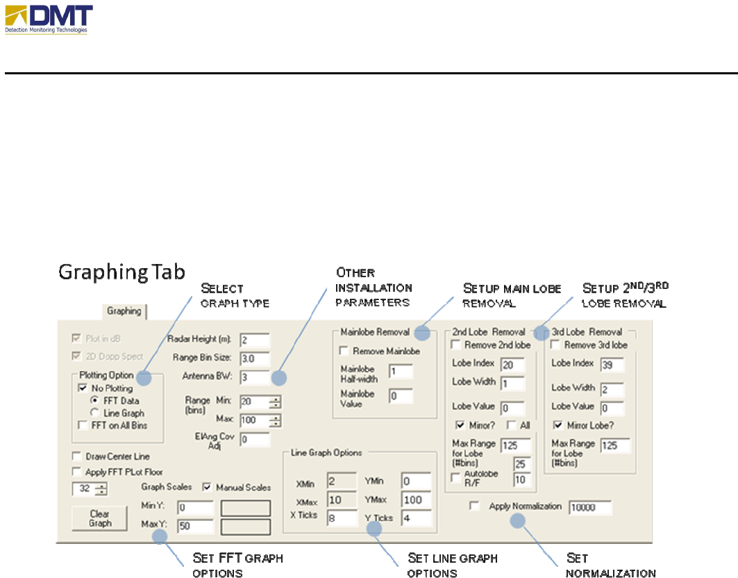
4.2.4 Graphing Tab
The Graphing Tab (below) defines the attributes that affect the display of the data processed.
Additionally, this tab allows the set some installation values (height, antenna beam-width) and to
apply some data filtering (lobe removals, normalization).
4.2.4.1 Select Graph Type
The Graph Type options include;
• No Plotting. Disables graph plotting on Server.
• FFT Data. Selects FFT Data plotting.
• Line Graph. Selects Line Graph plotting.
• FFT on All Bins. Enables FFT processing of all bins. Otherwise only those defined
within min and max Range bins are processed.
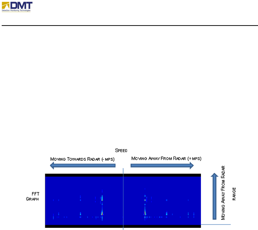
The blue FFT graph (below) displays data based on Doppler (frequency shift) and amplitude
data. A vertical bar down the center of the screen indicates the area where no Doppler
component was detected (non-moving). Objects moving away from the radar appear to the right
while objects approaching the radar appear to the left of center. The bottom of the screen depicts
AIMS Fast-Scan Radar v3.22 Installation and Operations Manual
DMT, LLC • DMT-M200-311 • 08/2009
33
the position of the radar (0 distance) while the top depicts the maximum range (max range bins).
The color of the object depicts the intensity of the received signal (blue – white – red).
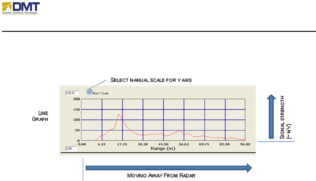
The line graph provides a simpler display depicting the strength of the peak received signal
versus distance from the radar. The default mode is autoscale where the Y axis auto ranges
based upon the most recent sample (a check box allows manual scale – discussed later).
4.2.4.2 Set FFT Graph Options
The Graph tab can be used to display the Doppler data from the AIMS Server. This is normally
used during system installation and setup or for diagnostic purposes and should not be left on
during normal operation. In addition to providing a graphical representation of the Doppler data
positioning the cursor on the graph provides distance and speed of objects of interest (Graph
Reference). The Set Scales command is used to affect the dynamic range of colors used in
displaying the data. Doppler data is viewed by selecting the Plot FFT Data option.
The FFT Graph options include;
• Draw Center Line. Provides a visual alignment of where the center line is (0 Hz offset).
• Apply FFT Plot Floor. This selection applies the entered threshold (text box) to reduce
the plotting of signals not of interest.
• Manual Scales. Allows the user to set color range used to indicate signal intensity.
4.2.4.3 Set Line Graph Options
The Plot Line Graph option on the Line Graph tab plots the maximum Doppler return for each
range. This is essentially a two dimensional representation of the FFT data. When selected, a
line plot will be updated with each processing cycle of the AIMS Radar. The divisions on the
plot can be changed by entering new values for the number of X or Y ticks. The values for the Y
AIMS Fast-Scan Radar v3.22 Installation and Operations Manual
DMT, LLC • DMT-M200-311 • 08/2009
34
Axis, Ymin and Ymax can be set by selecting the Man Y Scale option. It is recommended that
the Plot Line Graph option be disabled when changing the values for graphing.
The Line Graph options include;
• YMin. When Man Y Scale is enabled for Line Graph, this parameter sets the minimum
Y-axis value.
• YMax. When Man Y Scale is enabled for Line Graph, this parameter sets the maximum
Y-axis value.
• YTicks. When plotting Line Graph, this parameter sets the number of Y-axis gradient
lines.
• XTicks. When plotting Line Graph, this parameter sets the number of X-axis gradient
lines.
4.2.4.4 Setup Main Lobe Removal
Main Lobe Removal (sometimes referred to as Clutter X or clutter notch) allows for the removal
of nuisance alarms around zero Doppler (very slow or non moving objects) by setting all values
in and around 0 Hertz to the Mainlobe Value. Clutter X is very useful for removing the response
from swaying trees, moving water, or windblown heavy brush. Setting Clutter X too high can
reduce the ability of detecting walking humans.
The Main Lobe Removal options include;
• Remove Mainlobe. Enables the main lobe removal.
• Mainlobe Half-Width. The Mainlobe Half-Width represents the number of Doppler bins
(frequency slices) around 0 Hertz that are set. “0” in this text box equals to 0 Hertz only.
“1” in this text box represents one Doppler bin on either side of 0 Hertz is set. Commonly
set values are 0 to 2.

AIMS Fast-Scan Radar v3.22 Installation and Operations Manual
DMT, LLC • DMT-M200-311 • 08/2009
35
• Mainlobe Value. Appropriate settings for the Mainlobe Value are usually 0 or negative
numbers. (Note: A negative number lowers the plotted color of the notch to black and
thereby, is easier to see when looking at Doppler Plot). However, this value should be set
to zero when Autolobe is being used.
4.2.4.5 Setup 2
nd
/3
rd
Lobe Removal
Additional lobe removals may be necessary to eliminate noise generated by swaying trees, power
lines, roof fans, windmills, etc.
The 2
nd
and 3
rd
Lobe Removal options include;
• Remove 2
nd
/3
rd
lobe. Enables lobe removal.
• Lobe Index. Locates the lobe by frequency index.
• Lobe Width. Defines the width of the lobe area.
• Mirror. Enables the removal of a mirrored lobe (+/- freq index)
• Max Range for Lobe. Sets range to apply lobe removal, in bins.
For just the 2
nd
lobe removal there are a couple additional options;
• Autolobe R/F. Enables auto location and setting of 2
nd
lobe. The auto lobe function
constantly searches across the FFT data for peak sustained levels around a specific
frequency index and across consecutive range bins. When enabled, this function reports
(DSP Tab) the frequency index values for highest and next highest results.
• All. Enables the removal of all harmonic lobes (+/- n*freq index)
4.2.4.6 Apply Normalization
Normalization is used to reduce the value of the reported signal level before processing, applied
only when the received signal levels are consistently reported very high. When enabled, the
normalization function divides the data values by the number entered in the adjacent text box.
The function is rarely used.
4.2.4.7 Other Installation Parameters
Other installation parameters include;
• Radar Height. Sets height of radar installation (off ground).
• Antenna BW. Sets the antenna horizontal beamwidth value used by autoscanning feature
and used to calculate coverage %.
• Range Min. Sets minimum distance for detection (in bins).

AIMS Fast-Scan Radar v3.22 Installation and Operations Manual
DMT, LLC • DMT-M200-311 • 08/2009
36
• Range Max. Sets maximum distance for detection (in bins)
• ElAng Cov Adj. Sets offset adjustment for antenna elevation.
AIMS Fast-Scan Radar v3.22 Installation and Operations Manual
DMT, LLC • DMT-M200-311 • 08/2009
37
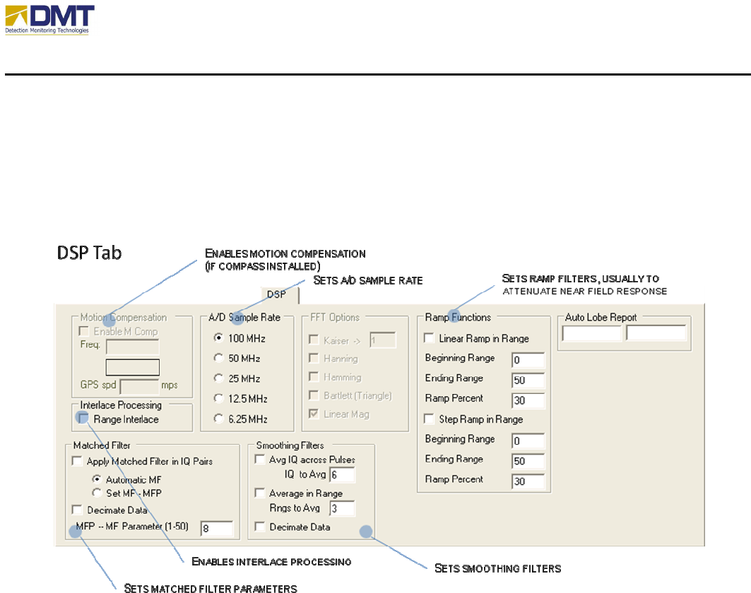
4.2.5 DSP Tab
The DSP Tab (shown below) provides the user the ability to affect changes to the digital signal
processing functions performed on the received signal.
4.2.5.1 Motion Compensation
When enabled, the software corrects for any detected motion of the radar (vehicle) itself. Motion
compensation parameters include;
• Enable M Comp. Enables motion compensation. The motion compensation algorithm
looks primarily for the effects of linear motion in the collected data and digitally corrects
it.
Also displayed in this area are;
• Freq. Reports the amount of Doppler shift resulting from the radar’s movement.
• GPS speed. Reports the speed provded by GPS unit.

AIMS Fast-Scan Radar v3.22 Installation and Operations Manual
DMT, LLC • DMT-M200-311 • 08/2009
38
4.2.5.2 A/D Sample Rate
The A/D Sample Rate is set automatically based on the Radar Range selection to allow the best
range resolution while maintaining full coverage for the maximum range selected. The A/D
board may be configured to sample data at various frequencies;
• 100 MHz (3m range bins)
• 50 MHz (6m range bins)
• 25 MHz (12m range bins)
• 12.5 MHz (24m range bins)
• 6.25 MHz (48m range bins)
The faster the sampling rate, the better the resolution but it also requires a longer processing time
(usually set to either 50MHz or 100MHz).
4.2.5.3 Matched Filter
The Matched Filter is a digital signal processing technique that matches the receiver
characteristics to the transmitted characteristics. More directly, the pulse width and pulsed shape
are matched. Since the radar pulse for AIMS is very square (that’s a good thing), the matched
filter can be generated by simply matching receiver gate width to the transmitted pulse width.
This is accomplished by coherently summing the range bins until the sum equals the pulse width.
Since pulse width is in nanoseconds, it must be converted to meters (pw (meters) = pw
(nanoseconds) * (3*10
8
). This implementation is sometimes referred to as a “boxcar” matched
filter. The result is improved range performance and clutter rejection. The size of the filter is a
function of the pulse width or length and can be set for Auto calculation (Auto MF) or set
manually (Set MF to MFP). Auto MF will allow the radar to calculate the appropriate number of
range bins needed to match the pulse width automatically. Set MF allows the user to override
the automated calculation. DMT has found that performance for the radar is often better when
the MF constant is a little lower than the value calculated by the Auto MF procedure. The MF
constant value is set and reported in the text box in the lower right corner of the Matched Filter
settings box. The matched filter routine is implemented before the FFT algorithm.
Decimating data permits the MF algorithm to step thru range bins at a step size equal the MFP.
This differs from the normal MF step size of 1. The result is fast processing, but at the cost of
degraded resolution.
The matched filter options include;
• Apply Matched Filter in IQ Pairs.
• Automatic MF.
• Set MF-MFP.
• MFP – MF Parameter (1-50).

AIMS Fast-Scan Radar v3.22 Installation and Operations Manual
DMT, LLC • DMT-M200-311 • 08/2009
39
• Decimate Data.
4.2.5.4 Smoothing Filter
The smoothing filters are used to average out spurious signals from legitimate detections and
may be applied across both the time domain (across pulses) and spatially (across range).
The smoothing filter options include;
• Average IQ across pulses. When enabled, this function averages the raw IQ values
across successive pulses (defined by the IQ to Average value). Ideally, the effect
suppresses spurious emissions occurring around the same time as signals received from
valid targets.
o IQ to Average.
• Average in Range When enabled, this function averages the raw IQ values across
successive range bins (defined by the Ranges to Average value). If Decimate Data is
enabled, the averaging increments by the Ranges to Average value (rather than one).
Again, the ideal effect will suppress spurious emissions co-located around valid targets.
o Ranges to Average.
o Decimate Data.
4.2.5.5 FFT Options (disabled)
Currently this function is disabled for user modification and is permanently set to Linear
Magnitude. Contact DMT to receive an enabled version. These options are FFT windowing
functions – each with its own merits. All help to reduce frequency sidelobes generated by the
FFT, but at the sacrifice of signal strength.
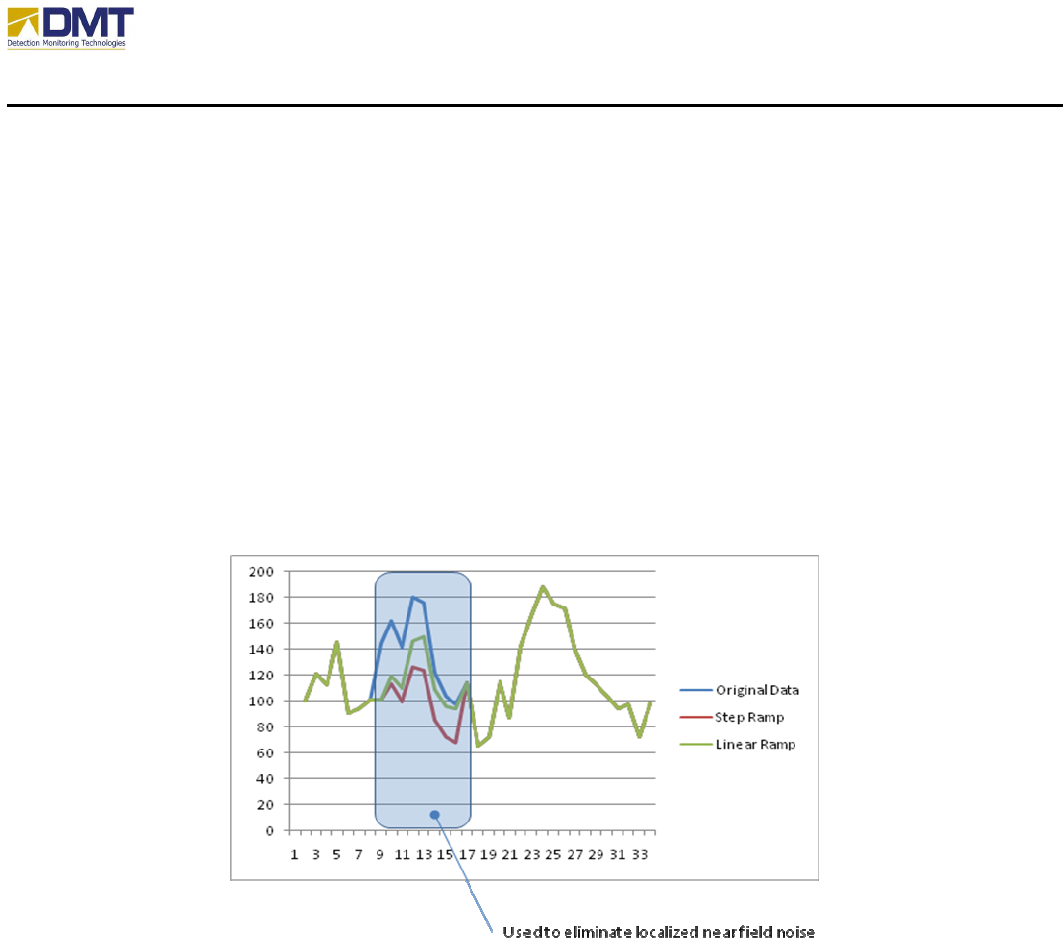
4.2.5.6 Ramp Functions
The ramp functions are used to digitally lower signal strength over a given range swath. They are
particularly useful for reducing the affects of processing artifacts generated from very large
objects located at close ranges. Large objects at close ranges can reflect so much energy that it
saturates the radar at that range. Saturation can cause false target detection.
The ramp function options include;
• Linear Ramp in Range
o Beginning Range.
o Ending Range
o Percent
AIMS Fast-Scan Radar v3.22 Installation and Operations Manual
DMT, LLC • DMT-M200-311 • 08/2009
40
• Step Ramp in Range.
o Beginning Range.
o Ending Range
o Percent
Ramp functions lower the signal strength to levels below alarm thresholds. The Beginning Range
indicates the first range bin for which the function is applied and the Ending Range indicates the
final range bin. The Ramp Percent represents that maximum percentage applied to the measured
magnitude (signal strength). So a Ramp Percent value of 30 means that the signal strength will
be reduced to 30% of its current value. Linear Ramp in Range means the reduction is applied
over a linear slope from 0 to Ramp Percent, which the above example is 30%. This linear slope is
applied over the Beginning Ranges to Ending Ranges. Step Ramp in Range means the reduction
is an equal percentage over the entire range swath defined (Beginning Range to Ending Range).
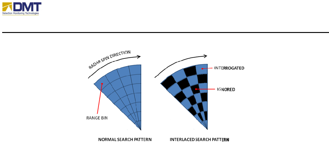
4.2.5.7 Interlace Processing
Range interlacing is an algorithm that mimics the methods used by search and recue teams to
quickly scan large areas in less time. DMT has added this algorithm to speed up search by
reducing the number of range bins that must be processed. Figure 8 illustrates this principle.
The process should only be used when rotation speed of the radar becomes critical.
AIMS Fast-Scan Radar v3.22 Installation and Operations Manual
DMT, LLC • DMT-M200-311 • 08/2009
41
4.2.5.8 Auto Lobe Report
If Autolobe R/F is enabled (Graphing Tab), the auto lobe information is output here. The first
value (on left) reports the frequency index of the primary autolobe. The second value represents
the frequency index of the next highest autolobe detected.
AIMS Fast-Scan Radar v3.22 Installation and Operations Manual
DMT, LLC • DMT-M200-311 • 08/2009
42
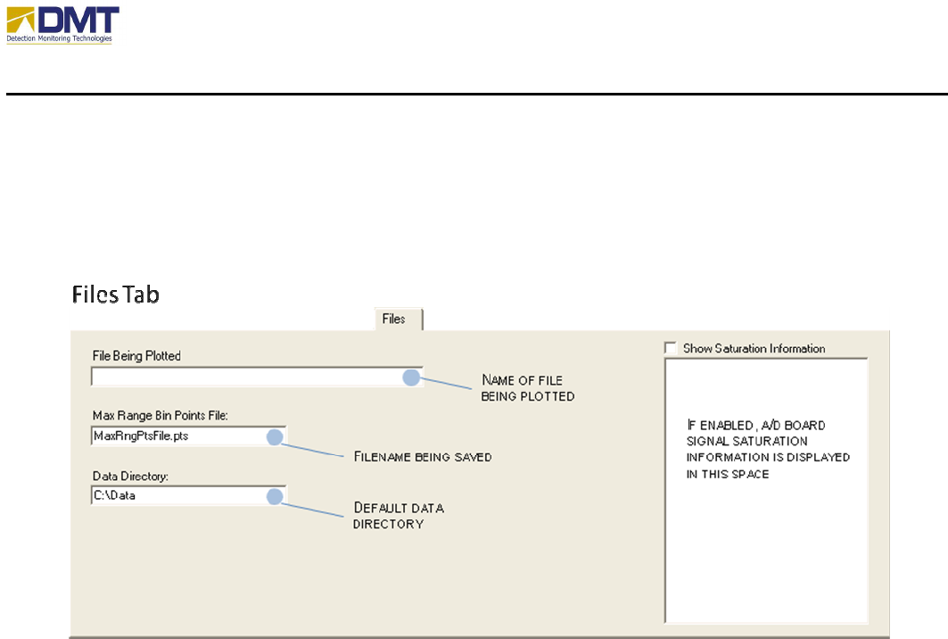
4.2.6 Files Tab
The Files Tab is shown below.
The configurable parameters in this tab include;
• Files being plotted. When the Replay Mode is enabled (Operations Tab) this field shows
the name of the files that contains the data being replayed.
• Max Range Bin Points File. This field contains the name of the files where data is
currently being saved in.
• Data Directory. This field contains the name of the subdirectory where data is being
saved to (when enabled).
• Show Saturation Information. When enabled, saturated signal level information is sent to
this box. For each range bin containing saturated points, the range bin number is
identified in the leftmost column and the column to the right reports the number of
saturated points in that range bin.
AIMS Fast-Scan Radar v3.22 Installation and Operations Manual
DMT, LLC • DMT-M200-311 • 08/2009
43
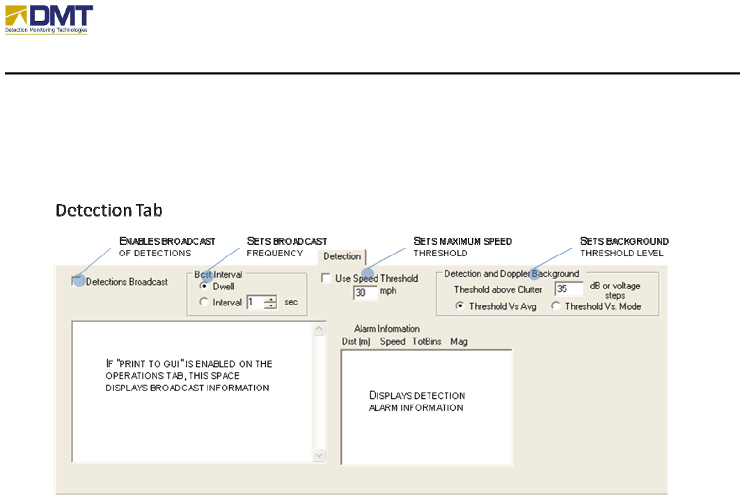
4.2.7 Detection Tab
The detection tab options include;
• Detections Broadcast. Enables the broadcast of detections.
• Bcst Interval. Sets the broadcast interval on each dwell, or on a specific time interval.
• Speed Threshold. Sets a maximum speed threshold to reduce reported detection activity.
The Use Speed Threshold is an option that can be used to focus on targets of interest. The
threshold limits reported detections to targets traveling slower than the threshold speed;
for example only targets traveling 10mph or slower.
• Detection and Doppler Background. Sets noise threshold relative to the Average or
Mode value ((max + min)/2) calculated across the range bins. When using the client
interface this value is referred to as the Sensitivity setting.
There also two display boxes
• Broadcast Information. If “Print to GUI” (Operations Tab) is enabled, broadcast
detections information is printed to this box.
• Alarm Information. Detected alarm information is sent to this box.

AIMS Fast-Scan Radar v3.22 Installation and Operations Manual
DMT, LLC • DMT-M200-311 • 08/2009
44
AIMS Fast-Scan Radar v3.22 Installation and Operations Manual
DMT, LLC • DMT-M200-311 • 08/2009
45
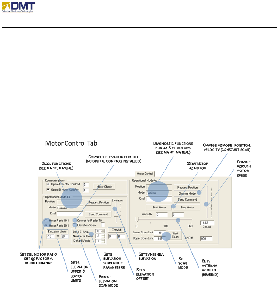
4.2.8 Motor Control Tab
Antenna movement and position can be controlled using the commands on the Motors tab. This
is primarily intended for use during initial setup, sensor tuning, and troubleshooting. When in
position mode the radar can be moved to a specific location (azimuth and elevation) by clicking
on the map. To operate in this mode select the Move Radar to Point on Map check box and
simply click on the map. Caution: Verify the Azimuth motor is in the Position Mode before
selecting this option. Problems with the antenna motors are indicated by AIMS Server via a
message to the AIMS Client. The AIMS Client will display “Error” for the reported position (Rpt
Pos), Figure 10.
4.2.8.1 Motor Controls
There are several commands available for working with the Azimuth motor. The primary
commands are Change Mode and Start/Stop Scan. Change Mode is used to transition the azimuth
motor between Position and Velocity modes. When in Position mode a sector scan can be
accomplished by setting lower and upper limits and clicking Start Scan. The button text will
change to Stop Scan and the azimuth motor will move between the lower (Lwr) limit and upper

AIMS Fast-Scan Radar v3.22 Installation and Operations Manual
DMT, LLC • DMT-M200-311 • 08/2009
46
(Upr) limit continuously until Stop Scan is clicked. Scan limits should be entered using negative
angles so that the minimum scan angle is always less than the maximum. For example, to scan
from 350 degrees to 20 degrees enter -10 to 20 for the minimum and maximum scan limits
respectively. The commands; Stop Motor, Get State, and Reset Motor were added for safety.
The Stop Motor command will send an immediate stop command to the motor. Once stopped the
Reset Motor command must be issued before any positioning or Change Mode commands can be
issued. The Reset Motor command starts the motor and sends it to the home or 0° position. Once
the motor has reached the home position it will automatically enter the position mode. The Get
State command will provides a status message that indicates the current mode of the motor;
position or velocity. The Position Mode and Velocity Mode options are intended to reflect the
status on the server only. The mode is changed by clicking on the Change Mode button. The
Change Mode button in the Azimuth antenna control toggles the Azimuth or Panning antenna
between the Constant Velocity mode (continuous spinning) and the Position mode. When
leaving the Constant Velocity mode the antenna will first return to the home position, 0°, before
entering the Position mode. Absolute position commands should not be issued until the antenna
has returned to the home position (Position Mode option is on). In position mode the slider can
also be used to position the antenna. As the slider is moved by clicking and holding the mouse
left button the angle is reported in the Goto Pos text box. When the slider is released, left mouse
button up, the go to position is transmitted to the AIMS Radar (server). The Elevation or Tilt
motor remains in the Position mode. Adjustments in elevation (tilt) are made using the slider bar
or by clicking on the map (assuming the Move Radar to Point on Map option is selected). To
change the elevation using the slider bar click, hold and move the slider to the desired angle and
release. As the slider is moved the angle will be reflected in the Set El Pos text box. When
released this elevation position will be transmitted to the radar. As the Antenna moves to a new
location the angle will be reported in the Current El Pos text box.
The elevation and azimuth motors are ‘smart’ motors and are managed via a special protocol.
Generally, the standard motor settings meet the needs of most installations. Occasionally,
however, modifications to basic motor settings are necessary because of the specific equipment
installed. For instance, a very large antenna would not be able to accelerate as quickly as a small
antenna without incurring vibration that would impact both the radar and the viewed image of a
camera mounted on top of the radome. The motor acceleration should be reduced to minimize
this potential impact. Changing the motor settings may be accomplished by typing the command
in the Cmd field and clicking on Send Command. To change acceleration you would type in the
Cmd field:
And click Send Command. More details may be found in the document “SmartMotor and
RTC3000 Controller Expanded Capabilities List”, dated May 5, 2001 (Animatics Corp). Before

AIMS Fast-Scan Radar v3.22 Installation and Operations Manual
DMT, LLC • DMT-M200-311 • 08/2009
47
using these commands you should consult with a certified DMT installer or DMT technical
representative.