DETECTION MONITORING TECHNOLOGIES AIMSFS-05X AIMS FAST SCAN RADAR SYSTEM (AIMSFS-05X) User Manual AIMS FS Radar I O Manual v1 0
DETECTION MONITORING TECHNOLOGIES, LLC (dba DMT, LLC) AIMS FAST SCAN RADAR SYSTEM (AIMSFS-05X) AIMS FS Radar I O Manual v1 0
Contents
Installation Guide 3
AIMS Fast-Scan Radar v3.22 Installation and Operations Manual
DMT, LLC • DMT-M200-311 • 08/2009
48
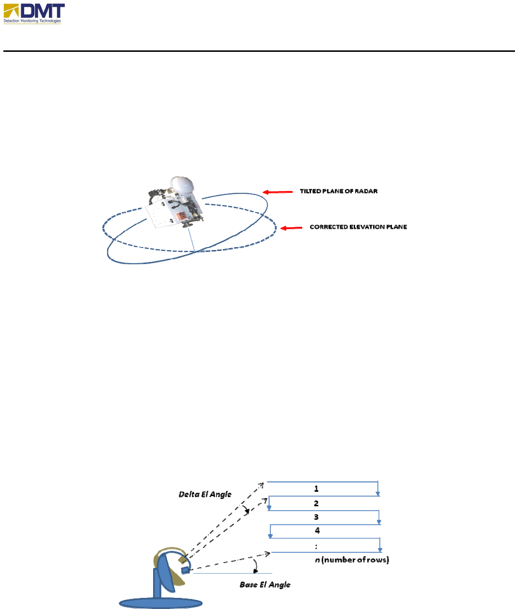
4.2.8.2 Tilt Compensation
The checkbox Correct for Radar Tilt enables the software to recalculate the horizon by creating
a new array of elevation settings based upon the tilt information provided by the compass (if
installed).
4.2.8.3 Elevation Scan
Elevation scan is used to search an area in the elevation domain where the area being search is
broader than the vertical beamwidth of the antenna. On the completion of each azimuth scan
range, the elevation is adjusted by the Delta Elevation Angle. Upon the completion of Number of
Rows, the direction of elevation scan is reversed (up-down-up-down…)
The elevation scan is defined by:
• Base Elevation Angle
• Number of Rows
• Delta Elevation Angle
AIMS Fast-Scan Radar v3.22 Installation and Operations Manual
DMT, LLC • DMT-M200-311 • 08/2009
49
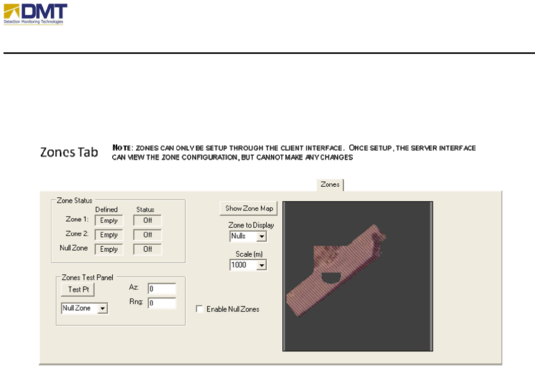
4.2.9 Zones Tab
Zones are setup through the client interface and this panel only allows the user at the AIMS radar
server to view the zone definitions. Setup and configuration of zones are discussed in the AIMS
Client operating manual.
AIMS Fast-Scan Radar v3.22 Installation and Operations Manual
DMT, LLC • DMT-M200-311 • 08/2009
50
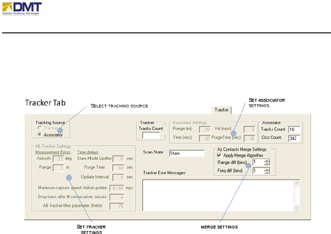
4.2.10 Tracker Tab
The Tracker Tab (shown below) is used to set the settings of the tracker software.
Please note that only the Associator is currently enabled and all the features that uniquely affect
the performance of the AB Tracker have been temporarily grayed out (inoperable).
4.2.10.1 Merge Settings
The merge settings are used to help reduce redundant contact reports from the same detected
target (item of interest). When applied, the merge algorithm collapses a stream of contiguous
contacts to a single contact report located where highest detection value was reported. The
merge settings include;
• Apply Merge Algorithm. Enable/disable the merge algorithm.
• Range difference. Defines the size of the area (in range bins) to include in the merge set.
• Frequency difference. Defines the speed variance (in freq guard bins or indices) of
detections to include in merge set.
4.2.10.2 Select Tracking Source
The tracking source can be either the Tracker (AB Tracker) or the Associator;

AIMS Fast-Scan Radar v3.22 Installation and Operations Manual
DMT, LLC • DMT-M200-311 • 08/2009
51
• The Associator is an elemental tracking algorithm that builds basic tracks on adjacent
contact detections (within defined range).
• The Tracker is a more sophisticated alpha-beta tracking algorithm that includes track
projection and probability of error for track continuation (discussed in detail in separate
application note).
4.2.10.3 Set Tracker Settings
The Tracker settings include;
• Azimuth
• Stare Mode Update
• Range
• Purge Time
• Update Interval
• Max capture speed
• Drop track after # consecutive misses
• AB Tracker filter (theta)
4.2.10.4 Set Associator Settings
The Associator settings include;
• Range. Defines the maximum range between points to associate.
• Velocity. Defines the speed differential
• Time. Defines the maximum time between contiguous detections for association.
• Purge Time. Defines the time to “age out” an Associator track.
AIMS Fast-Scan Radar v3.22 Installation and Operations Manual
DMT, LLC • DMT-M200-311 • 08/2009
52
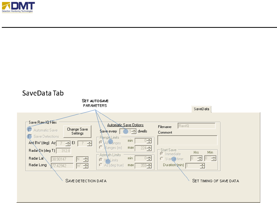
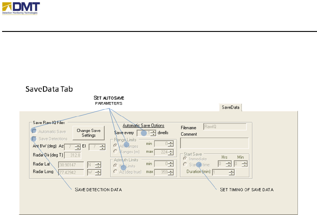
4.2.11 SaveData Tab
The SaveData Tab is fairly self-explanatory as this tab is used to establish the conditions and
filename attributes that define how Raw IQ data files are saved.
4.2.11.1.1 Autosave Parameters
The Autosave settings include;
• Automatic Save
• Save Every x dwells.
• Range Limits.
• Azimuth Limits
4.2.11.1.2 Manual Save Parameters
The manual save settings include;
• Save Detections
• Start Save
o Immediate
o Timed.
Start Time

AIMS Fast-Scan Radar v3.22 Installation and Operations Manual
DMT, LLC • DMT-M200-311 • 08/2009
53
Duration
4.2.11.1.3 RawIQ File Saves
The file saving option allows raw IQ data to be stored on the local hard drive in the directory,
c:\Data. The file names used will be the system time preceded by the string value listed in the
text box, “File Name Base”. Enter the desired file name and check the Save RawIQ File box.
Uncheck the box to stop saving data files.
4.2.11.1.4 Other Parameters
The following values are annotations that are stored with the saved data file(s);
• Ant BW
o Az – Azimuth. The horizontal (or azimuth) beamwidth of the antenna.
o El – Elevation. The vertical (or elevation) beamwidth of the antenna.
• Radar Dir. The absolute bearing of the radar home position. If a digital compass is
installed, this information is updated on initialization or when Update HPR (Compass
Tab) is selected.
• Radar Lat. The geo-positional latitude coordinates of the radar installation. If a GPS is
installed, this information is periodically updated.
• Radar Long. The geo-positional longitude coordinates of the radar installation. If a GPS
is installed, this information is periodically updated.
AIMS Fast-Scan Radar v3.22 Installation and Operations Manual
DMT, LLC • DMT-M200-311 • 08/2009
54
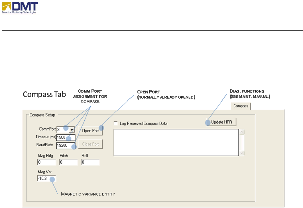
4.2.12 Compass Tab
The Compass Tab settings include;
• Comm. Port Assignment. The compass communicates over a serial I/O link
o CommPort. Sets the serial port connected to the compass.
o TimeOut. Communications timeout value.
o BaudRate. Data communications rate.
• MagVar. The magnetic variance, if available, should be entered for the specific region of
activity.
• Log Received Compass Data. Selecting this box enables the saving of received compass
data into the log file.
• Update HPR. To receive updated heading, pitch, and roll information from compass,
click on this tab.
AIMS Fast-Scan Radar v3.22 Installation and Operations Manual
DMT, LLC • DMT-M200-311 • 08/2009
55
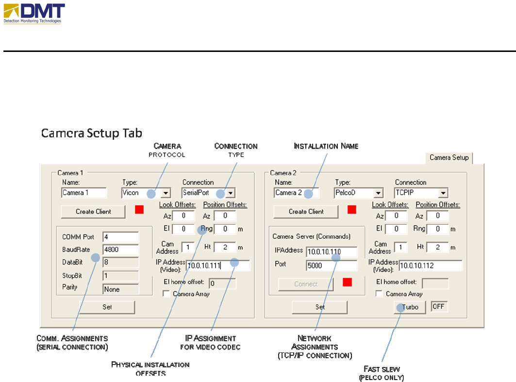
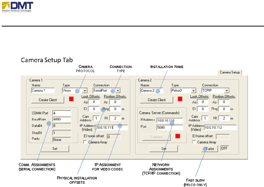
4.2.13 Camera Setup Tab
4.2.13.1.1 Camera Parameters
For each camera, the settings include;
• Name. Unique name to identify camera setup.
• Type. Camera type (Vicon, Pelco, Pelco-D… etc.). The type identifies the
communications protocol, configurable attributes and default communications
parameters. At current, the AIMS software supports the following types;
o None
o DI5000
o TASS
o QuicksetN2
o Vicon
o PelcoD. If Pelco is selected, the Turbo button is enabled to allow the user to
activate a fast slew.
o LRAD
o SentryII
o Vumii
• Connection

AIMS Fast-Scan Radar v3.22 Installation and Operations Manual
DMT, LLC • DMT-M200-311 • 08/2009
56
o SerialPort
COMM Port
BaudRate
DataBit
StopBit
Parity
Cam Address.
o TCPIP
IPAddress
Port
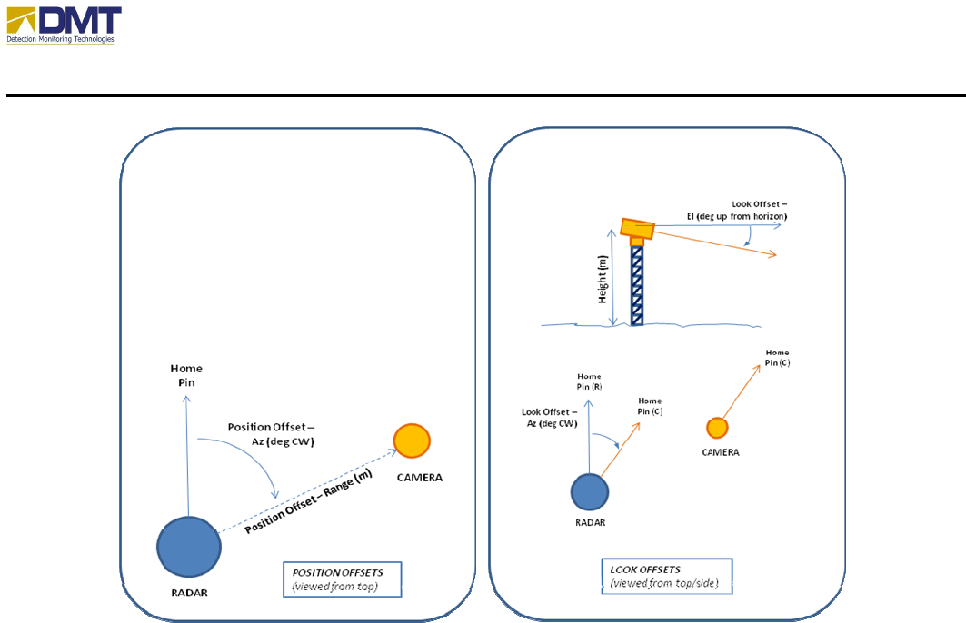
• Offsets.
o Look Offset – Az. This offset value defines the azimuth angle difference between
the home pins of the radar and the camera (see drawing below).
o Look Offset – El. This offset value defines the difference in degrees between the
camera look angle (at 0º elevation) and the horizon (up is positive).
o Position Offset – Az. This offset value defines the location (in degrees
clockwise) the camera is positioned relative to the radar home pin.
o Position Offset – Rng. This offset value defines the absolute distance the camera
is positioned relative to the radar (in meters).
o Height. This offset value defines the height the camera is positioned above the
ground.
• IP Address (Video). The IP address of the video codec/server that digitizes the camera’s
output video stream (usually inside the UCM).
• Camera Array. This selection is used to support a very specific application involving
four cameras installed at 90º angles and communicating on a single multidrop serial
communications line. More detail may be found in the DMT document, “Camera
Alignment and Operation Procedures for AIMS EA-System” (dated 1/23/2008).

AIMS Fast-Scan Radar v3.22 Installation and Operations Manual
DMT, LLC • DMT-M200-311 • 08/2009
57
AIMS Fast-Scan Radar v3.22 Installation and Operations Manual
DMT, LLC • DMT-M200-311 • 08/2009
58
4.3 Required Configuration Settings
As mentioned previously, the configuration of most all of the AIMS Fast-Scan system features
should be performed through the client interface. There are, however, a few features that must
be setup directly through the server interface; these include;
• Setting the network parameters
• Configuring the Cameras
• Configuring the Compass
• Configuring the GPS
Normally, optional hardware (such as cameras, compass and GPS) is ordered at the time of
original sale. In which case, their physical installation and configuration would be completed
and operationally tested at the factory prior to shipment. Sometimes, however, these options
were either not available or foreseen as a requirement at the time of order.
4.3.1 Setting the Network Parameters
The network configuration parameters are used to set the IP address for the AIMS Fast-Scan
Server. Unless the network parameters are known before the time of shipment, these values will
have to be changed to reflect the individual need for each site.
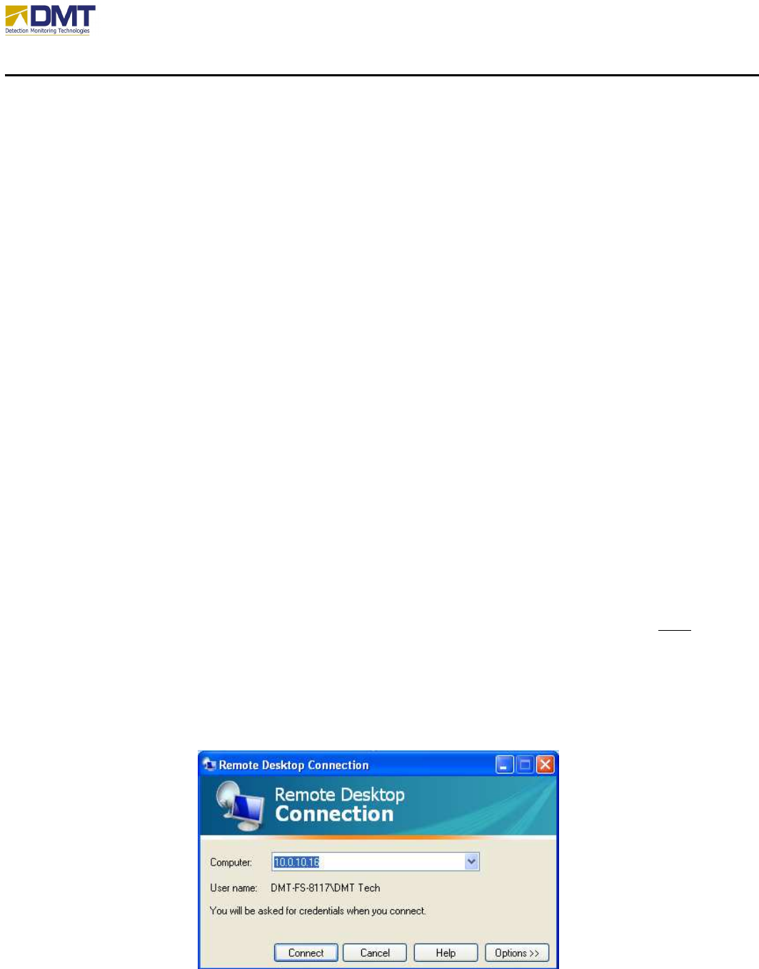
In order to set the network parameters, the user must first login into the server computer using
Remote Desktop (on original configuration, Remote Desktop services are enabled). You must
know the current address setup on the server to enable a remote desktop connection – which
should be indicated on unit (tape with IP address written on it) or provided on the paperwork
received with unit.
Remote Desktop can usually be found under Start - All Programs – Accessories.
AIMS Fast-Scan Radar v3.22 Installation and Operations Manual
DMT, LLC • DMT-M200-311 • 08/2009
59
Enter in the IP address of the AIMS radar server and click on Connect.
You will then be asked for your Username and Password. On all DMT units, an account is
created for “DMT Tech” with a password “dmtllc” (case – sensitive).
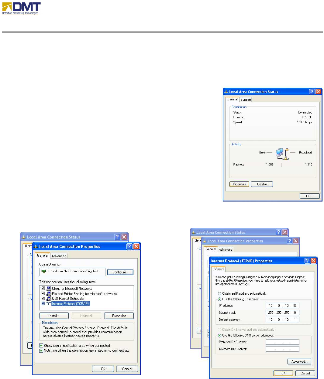
The network parameters are set using the standard Windows XP
local area network configuration screen, accessed by selecting
Control Panel - Network Connections - Local Area Connection,
which should generate a screen similar to the one shown at right.
To modify the network parameters, select the button Properties and
scroll down to select Internet Protocol (TCP/IP) and select
Properties (again). This will generate a new window that will
allow you to enter the new IP address, subnet mask and gateway
(lower right).
Be very careful entering this information and record the new
values – once set, your Remote Desktop connection will be
terminated and you will need to login again with the new IP
address to verify it has been properly set.
AIMS Fast-Scan Radar v3.22 Installation and Operations Manual
DMT, LLC • DMT-M200-311 • 08/2009
60
4.3.2 Cameras
The standard AIMS camera controls
provide functionality for connecting to a camera’s pan/tilt
device (via either serial port or TCPIP connection), sending pointing commands to that device,
and displaying the video feed from the associated camera. The connection details required for
accomplishing these tasks are determined by the camera “type” selected and the setup parameters
entered in the Camera Setup control boxes, as described later. Note that the camera type
selection will automatically set the proper communications protocol for that camera.
1
There are two separate cameras defined and controlled by each AIMS Radar, referred to as
Camera 1 and Camera 2 throughout the Radar and Client programs. All camera commands
generated by either the Client program or the Radar program are directed to one or both of these
cameras depending on selections made by the user. Note that these camera designations
(Camera 1 and Camera 2) actually represent a camera type and a communications path for that
camera. For example, Camera 1 (or Camera 2) represents a single camera type (i.e., DI5000,
SentryII, PelcoD, etc.) connected to a camera controller through a TCPIP or serial port
connection. For a serial port connection, Camera 1 (or Camera 2) may actually represent
multiple cameras connected in a daisy-chain arrangement.
2
In this case, each individual camera
in Camera 1is addressed by a second parameter (Camera Address) which is selectable on the
Radar or Client control panels.
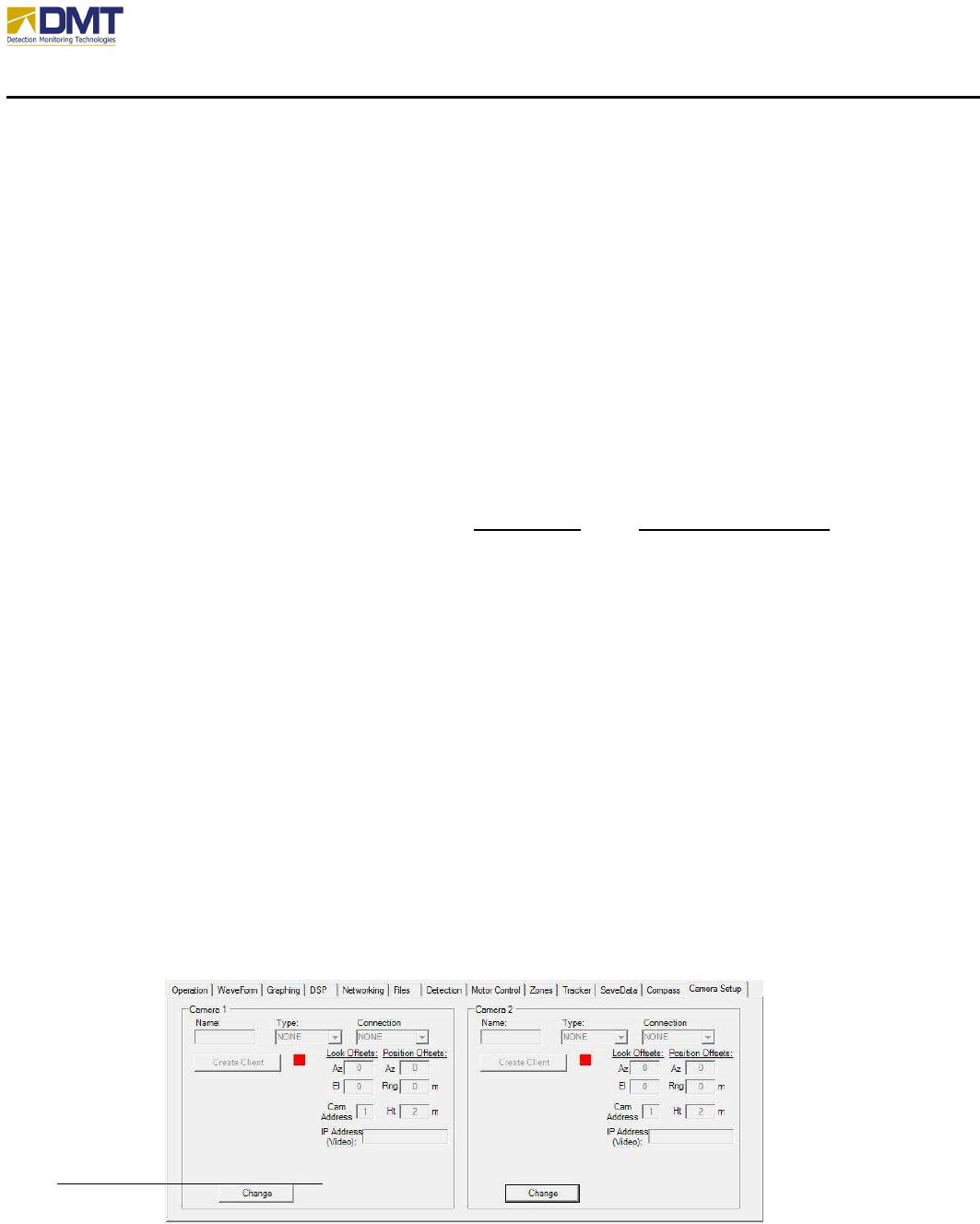
4.3.2.1 Camera Setup
The camera setup is performed by entering the appropriate information in the Camera 1 or
Camera 2 setup box located on the Camera Setup tab on the Radar program’s control panel.
Normally, this setup is performed only once, and is automatically restored on subsequent starts
of the AIMS Radar program as described later.
Note in the figure (below) the Camera Setup tab page on the Radar program control panel with
no selections made for either Camera 1 or Camera 2 (the default setup state).
1
Pelco D protocol Vers 2 Rev 1 for PelcoD, and ICD-TASS-001 for SentryII.
2
This is the control arrangement for the Pelco cameras in the EA-System configuration. Camera 1 is the pathway
used to communicate with any one of the four of the Pelco cameras.

AIMS Fast-Scan Radar v3.22 Installation and Operations Manual
DMT, LLC • DMT-M200-311 • 08/2009
61
The camera setup starts by clicking on the “Change” button to activate the controls in the
Camera 1 setup box. A camera type (such as PelcoD) may then be selected from the “Type”
dropdown box. Next, a connection type is selected in the “Connection” dropdown box. The
connection type refers to the camera’s pan/tilt controller (Serial or TCPIP). For the Pelco
cameras, a serial port connection is selected (COMM 3).
Camera 2 may be setup the same way.
Note that the camera and type selections will automatically select and enter the serial port
settings for each camera (BaudRate, DataBit, StopBit, and Parity). Other entries must be
entered by the user to complete the setup process. These entries include the following:
• Name: (Optional) A convenient name used to identify the camera assigned as Camera 1
or Camera 2 (This name entry appears in the Client Video selection box, described later)
• COMM Port: The Pelco cameras are controlled through COMM 3; the FLIR Sentry
camera is controlled through COMM 4. (These values must be entered as shown).
• Look Offsets:
3
Enter the LookOffAz, LookOffEl values for each the cameras as described
in section “4.3.2.5 Camera Look Offsets”.
• Camera Height: Enter the height of the camera above ground level in the Ht textbox.
• Camera Address: Used for multi-drop serial applications. Enter the camera address (1
..4) for the camera that will react to commands sent to Camera 1. (Can be left as “1” at
initial setup. This camera address value is normally set with other controls in the Radar
and Client software).
• IP Address (Video): Enter the IP Address of the video converter for the desired camera.
• Camera Array: Usually not checked, used for special application; detailed in “
Camera
Alignment and Operation Procedures for AIMS EA-System (dated 01/23/2008)”
.
3
The Look Offsets (as well as the Position Offsets) affect the accuracy of the camera pointing commands generated
by the AIMS Client (move to mouse click) and the AIMS Radar (slew to detection) programs. The default values of
“0” indicate that the Radar and camera are co-located and have home positions aligned.
AIMS Fast-Scan Radar v3.22 Installation and Operations Manual
DMT, LLC • DMT-M200-311 • 08/2009
62
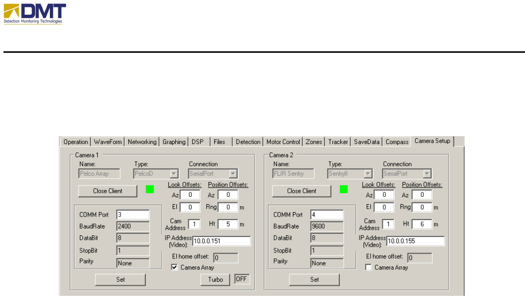
After completing these setup entries, the next step is to create a camera client object by clicking
on the “Create Client” button. This action creates the client object which opens the specified
serial port and provides two-way serial communications with the camera controller. The setup
box now appears as shown in the figure below.
AIMS Radar / Camera 2 setup box after creating camera client objects
If the camera object is created successfully, the caption on the create button changes to “Close
Client” and the light next to the button turns green.
After entering all setup parameters in the camera setup boxes, click on the “Set” buttons to
complete the Camera 1 and Camera 2 setup and update the internal settings in the new camera
objects. (The “Set” button causes two actions to occur: (1) the camera client object is updated
with the setup parameter entries, and (2) all connected AIMS Clients are updated to show the
new parameter values).
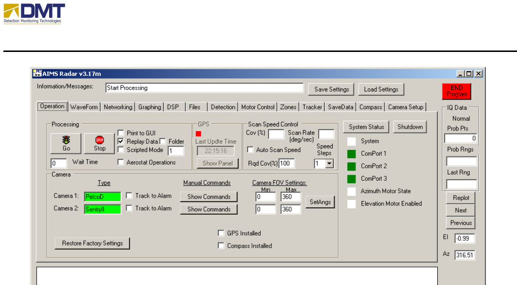
The main camera controls on the AIMS Radar, located on its Operation tab, will now change to
show the new setting for Camera 1 and Camera 2 as shown in Figure 2.4:
AIMS Fast-Scan Radar v3.22 Installation and Operations Manual
DMT, LLC • DMT-M200-311 • 08/2009
63
Once a camera has been defined, the camera type selection will appear in the “Type” textbox
(next to the Camera 1 or Camera 2 label) with a green background, and a “Show Commands”
button will appear on the Operation tab page. The Show Commands button activates a pop-up
window containing a set of controls for sending commands to that camera type.
At this point, the user should save the camera setup details by clicking on the Save Settings
button at the top of the Radar control panel. This action will update the AIMS Radar’s
configuration file, which will restore these settings with the next load or restart of the AIMS
Radar program.
The camera setup information is sent automatically to the AIMS Client when it connects to the
AIMS Radar. The AIMS Client display has similar camera setup controls which allow the user
to perform some but not all of the camera setup tasks described earlier.
4.3.2.2 Camera Pointing Commands
The AIMS Radar and Client programs are capable of generating movement commands for all
cameras integrated with an AIMS Radar. This feature allows the user to “point“ Camera 1
and/or Camera 2 using one of three basic control methods.
The basic control methods are listed as follows, and are described in the next subsections:
• Manual Pan/Tilt controls
AIMS Fast-Scan Radar v3.22 Installation and Operations Manual
DMT, LLC • DMT-M200-311 • 08/2009
64
• Point to Mouse Click
• Point to radar detection
4.3.2.2.1 Manual Pan/Tilt Controls
Both the Client and Radar programs provide a set of manual pan/tilt controls to continuously
move a camera while a button is depressed (slew left/right, up/down) or to move the camera to
specified azimuth and elevation location.
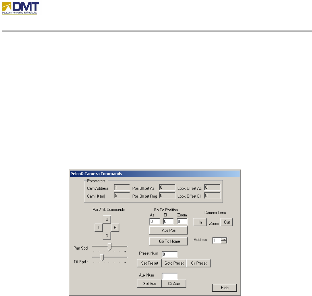
The manual controls on the Radar program are located on pop-up command windows, which are
activated by clicking on the Show Commands button for Camera 1 or Camera 2 located on the
Radar’s Operation tab page. The figure below shows the command window for the Pelco
camera.
AIMS Radar / Pop-up window for Pelco cameras pan/tilt controls.
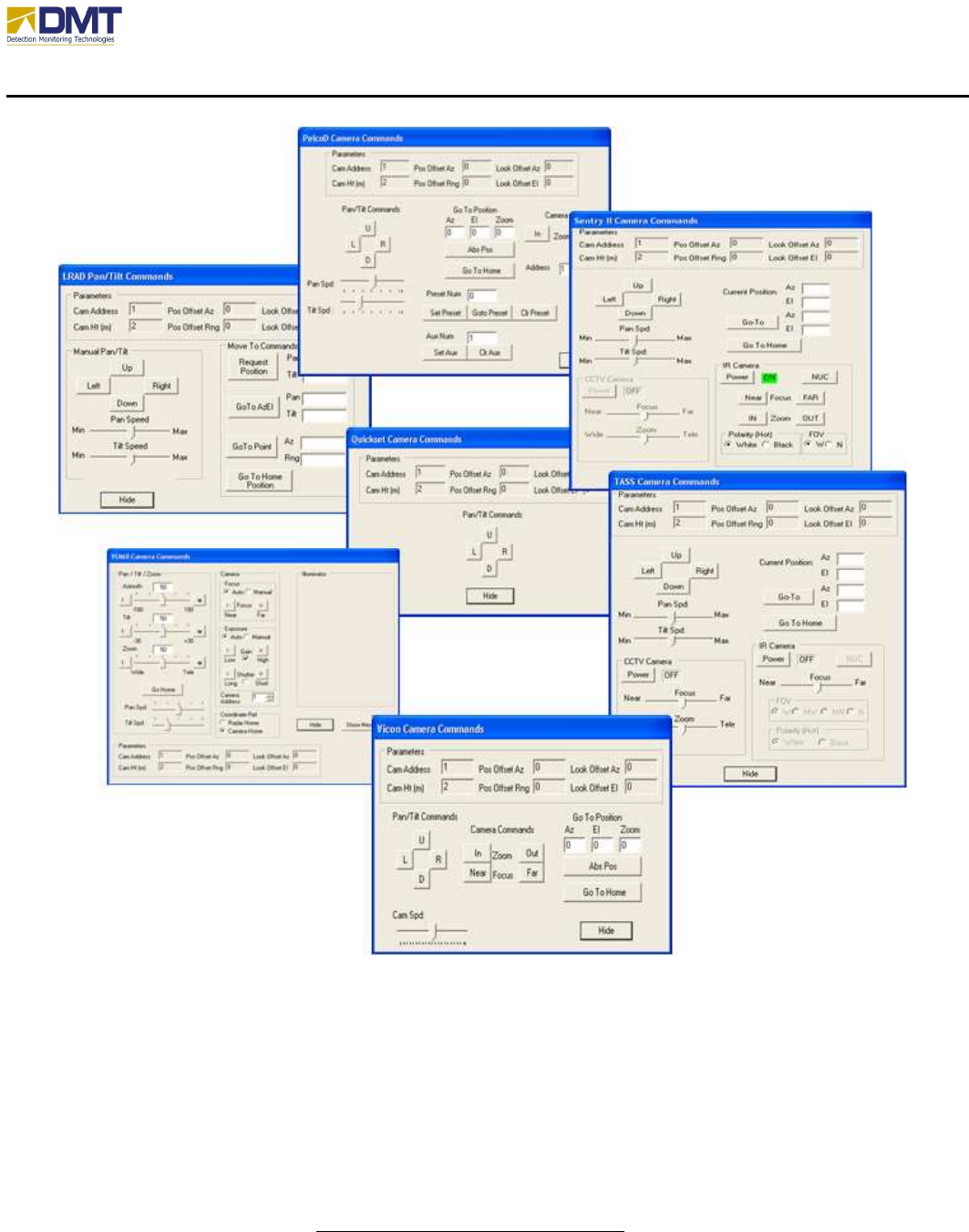
All camera pop-up command windows contain a Parameters box, which shows the current
settings for various parameters in the camera client object. Otherwise, the controls are generally
different for each camera type integrated into the AIMS software (see example screens below).
AIMS Fast-Scan Radar v3.22 Installation and Operations Manual
DMT, LLC • DMT-M200-311 • 08/2009
65
AIMS Radar / Pop-up windows for pan/tilt controls on various camera Types
The manual pan/tilt controls consist of four button controls (Up- Down –Left- Right or U-D-L-R )
which operate the same as the Client controls. The pan and tilt speed can be adjusted using the
Pan Spd and Tilt Spd slide bar controls.
Both command windows provide a “GoTo” control which will command the camera to move to
an absolute azimuth and elevation position. The values for these commands are entered as
azimuth and elevation angles relative to the Radar home position. That is, the cameras move to

AIMS Fast-Scan Radar v3.22 Installation and Operations Manual
DMT, LLC • DMT-M200-311 • 08/2009
66
the specified look direction as measured in the Radar’s local coordinate system (and not the
camera’s local coordinate system). The Look Offset values entered earlier with the camera setup
account for any differences in the Radar coordinate system and the individual camera coordinate
system.
Selecting the Go To Home button causes the camera to move to a look direction which is aligned
with the Radar home position.
4.3.2.2.2 Point to Mouse Click
This feature allows the user to quickly point any Camera attached to an AIMS Radar to a
geographic point on the Client’s PPI display. This action is performed by selecting the desired
camera for this command, and then clicking the mouse at the point on the PPI display. This
feature is discussed in more detail in the AIMS Client Manual.
4.3.2.2.3 Point to Radar Detection
Either or both Camera 1 and Camera 2 can be selected to point automatically at detections
reported by the controlling AIMS Radar. This selection can be made by checking the Track to
Alarms checkbox adjacent to the desired camera on the Client or on the Radar. When Track to
Alarms is selected for a camera, that camera will automatically point at each Radar detection as it
is declared.
The function is deactivated by un-checking the Track to Alarms checkbox.
4.3.2.3 AIMS Radar and Camera Alignment
The AIMS Radar software requires that several “alignment” parameters be determined for the
system configuration and entered into the Client and Radar control programs. This section
describes these parameters and illustrates the general procedure for determining their values.
These key alignment parameters are the Radar Direction (RadDir), the Look Offsets for each
camera (LookOffAz, LookOffEl), and the Position Offsets for each camera (PosOffAz,
PosOffRng). They are described briefly as follows:
• Radar Direction – The azimuth angle in degrees, measured positive clockwise, from True
North to the Radar’s look direction
4
at its home position. That is, the RadDir is the true
bearing of the Radar beam centerline at the Radar home position. This parameter is used
by the AIMS software to calculate the Latitude and Longitude values for detections and
4
The Radar look direction is the outward direction of the Radar beam centerline.
AIMS Fast-Scan Radar v3.22 Installation and Operations Manual
DMT, LLC • DMT-M200-311 • 08/2009
67
other display symbols on the Client PPI display. If the RadDir is not entered properly in
the AIMS Client and Radar programs, then Latitude/Longitude values calculated by the
Radar will be incorrect.
• Look Offsets – These angles measure the difference (azimuth and elevation) between the
Radar look direction at its home position and the camera look direction at its home
position. The LookOffAz is the azimuth angle in degrees, measured positive clockwise,
from the Radar to the camera. The LookOffEl is the elevation angle in degrees, measured
positive up, from horizontal to the camera look direction. These parameters are used by
the Radar software to calculate the proper pointing commands for the camera. Errors in
the LookOffAz and LookOffEl values will result in incorrect pointing commands sent to
the camera.
• Position Offsets – These offsets account for a camera being located at a different position
than the AIMS Radar. The PosOffAz is the azimuth angle (measured positive clockwise)
from the Radar look direction at its home position to the point where the camera is
located. The PosOffRng is the range in meters from the Radar to the camera position.
Errors in these values will result in incorrect pointing commands sent to the camera.
The AIMS control software will utilize the alignment parameters defined above to generate
correct geographic positions (Latitude and Longitude) and to generate the correct azimuth and
elevation angles for commanding cameras to point at radar detections and at geographic points
on the AIMS Client PPI display.
The next sections will describe how to measure the various alignment parameters using this
general diagram.
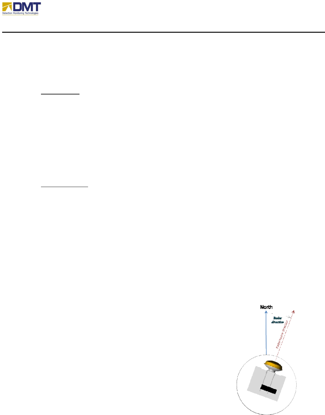
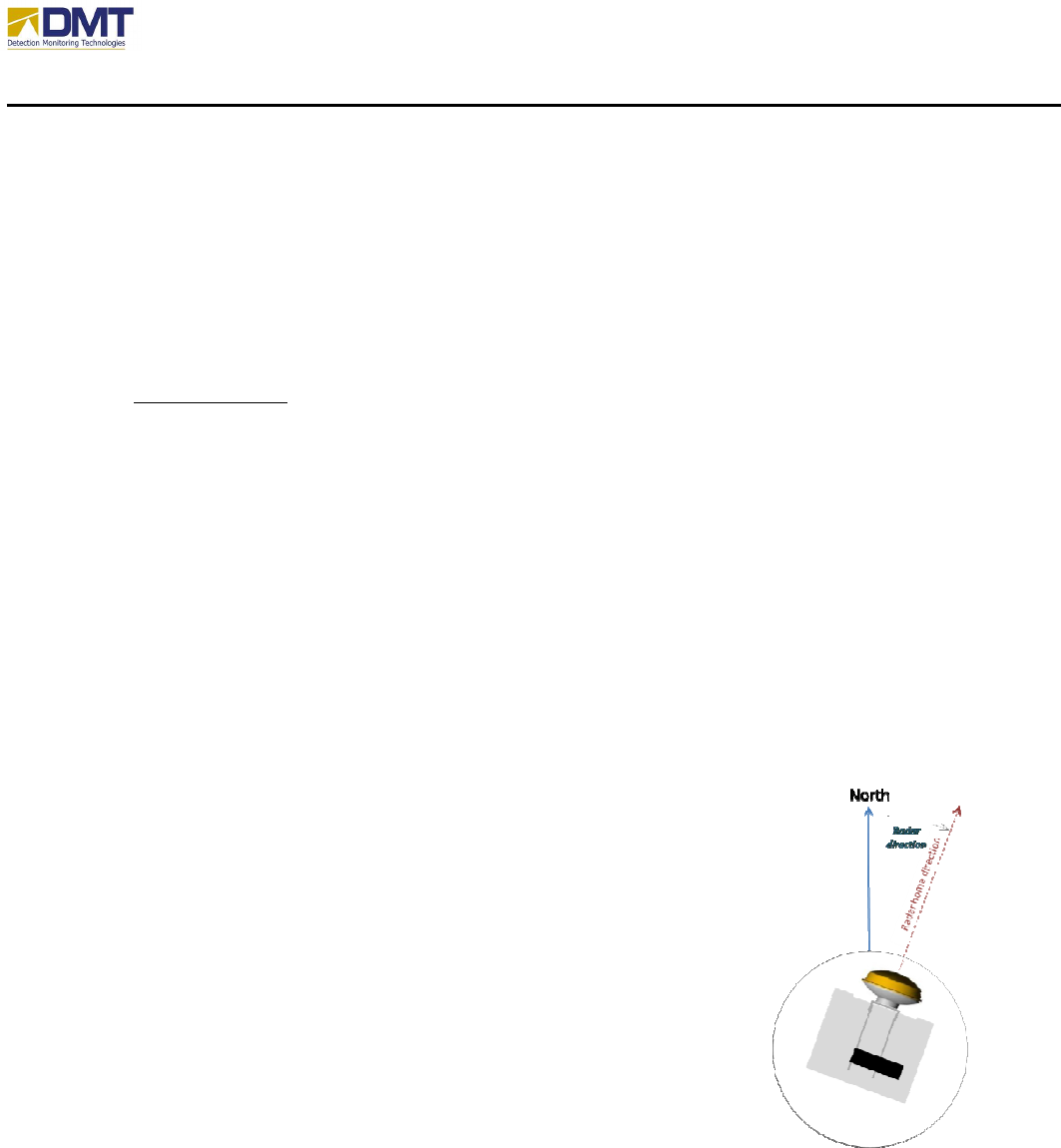
4.3.2.4 Radar Direction Measurement
The Radar Direction (RadDir) parameter measures the geographic
orientation of the Radar. The figure below shows the plan view with
the radome removed, the base plate exposed, and the AIMS Radar
visible and located at its home position.
The Radar Direction is the angle in degrees between True North and the
Radar home position. It is recommended that this direction be marked
on the base plate so that it can be seen once the radome is replaced.

AIMS Fast-Scan Radar v3.22 Installation and Operations Manual
DMT, LLC • DMT-M200-311 • 08/2009
68
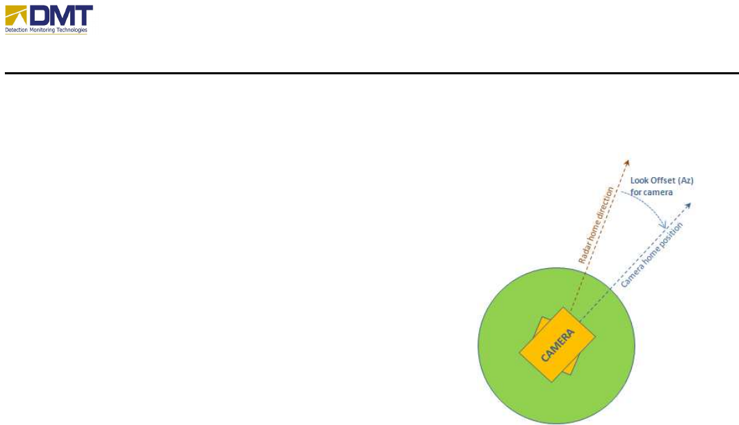
4.3.2.5 Camera Look Offsets
The figure at right illustrates the geometry for measuring the
Look Offset azimuth (LookOffAz) for a camera mounted on
top of the AIMS radome, with the Radar and the camera home
positions indicated.
The Look Offset elevation (LookOffEl) should also be set to
“0.” Note that the Radar orientation is expected to be level.
AIMS Fast-Scan Radar v3.22 Installation and Operations Manual
DMT, LLC • DMT-M200-311 • 08/2009
69
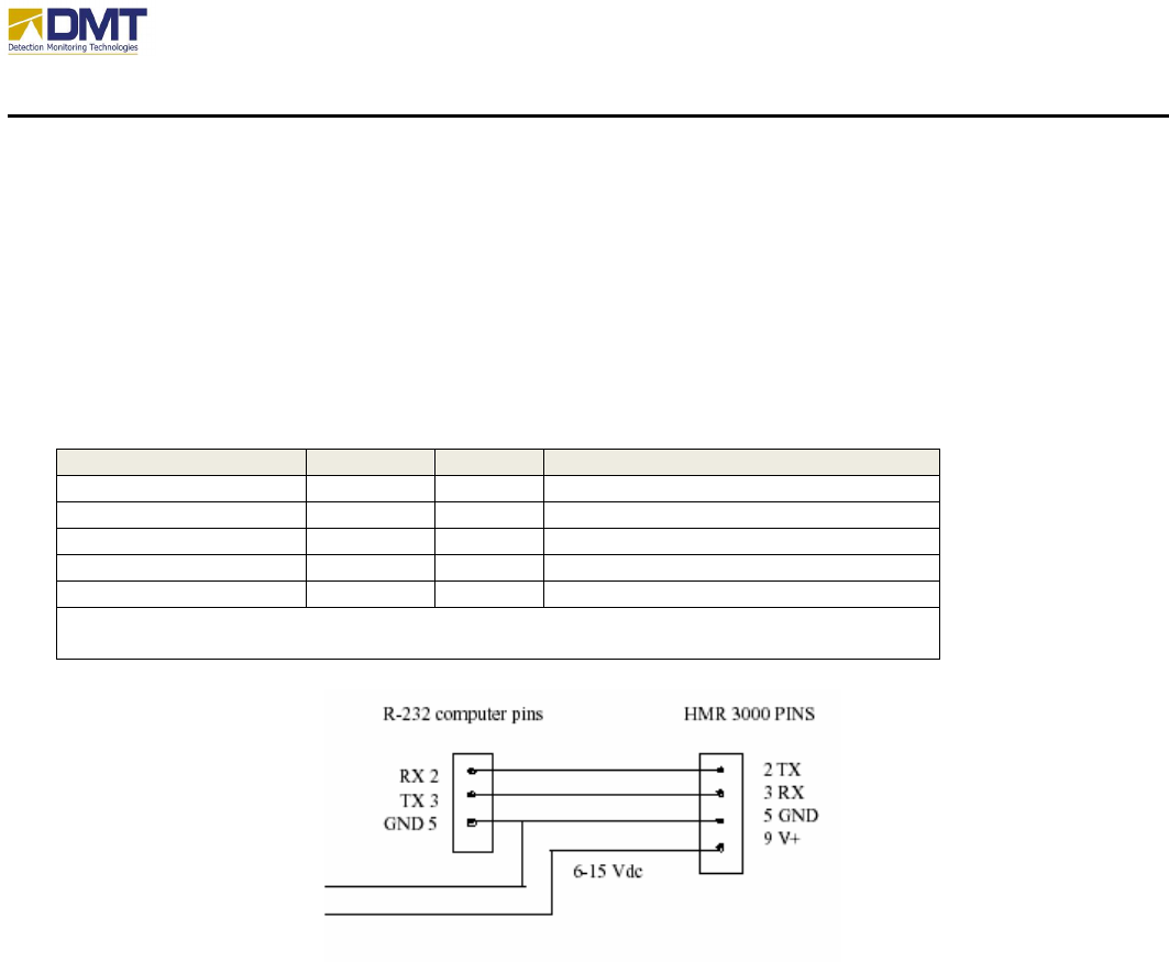
4.3.3 Compass
DMT has selected the Honeywell HMR3000 as the preferred compass device. The Honeywell
compass uses a 9-pin serial connector for communications with the AIMS radar. Power is also
provided via this connector (see drawing). The serial communications lines should be attached
to the serial I/O port on the CPU stack via the Molex connector block (pins 7,8 and 9).
Name
In/Out
Pin
Description
TxD
Out
2
RS232 Transmit / RS485 TxRx+
RxD
In
3
RS232 Receive / RS485 TxRx
-
GND
In
5
Power and signal common
5V
In
8
Regula
ted power input
6
-
15V
In
9
Unregulated power input
Caution: Do NOT exceed +5.5V at regulated power input (pin 8). Higher voltages
will damage components.
The HMR3000 should already be wired and attached to the stand-post behind the antenna, ready
for configuration.
After installation is completed, you will need restart the AIMS Radar server software and check
the box “Compass” on your Operation tab to begin using your Compass. The communication
parameters should be set on the Compass Tab to the following values;
• Port. COM5
• Baud Rate. 19200
• Data Bits. 8
• Parity. None
• Stop Bits. 1
AIMS Fast-Scan Radar v3.22 Installation and Operations Manual
DMT, LLC • DMT-M200-311 • 08/2009
70
4.3.4 GPS
DMT has selected the DeLorme Earthmate GPS LT-40 as the preferred GPS device. The GPS
uses a USB port on the computer stack for communications and power. The GPS draws
approximately 500ma of 5VDC power; a substantial portion of the available power from the
USB ports. It is assumed that the GPS unit is already mounted on a stand-post that is designed to
support the installation of the GPS and compass. Please insure that the GPS unit is secured with
either a tie-wrap or double-sided tape.
The GPS requires the support of a serial software emulation package; DeLorme Serial Emulator.
This software should already be installed on your system. If not, the installation software should
be available on your server hard disk drive under the subdirectory “C:\Setup\DeLorme”.
Simply run the installation file and your GPS unit will be available for operation.
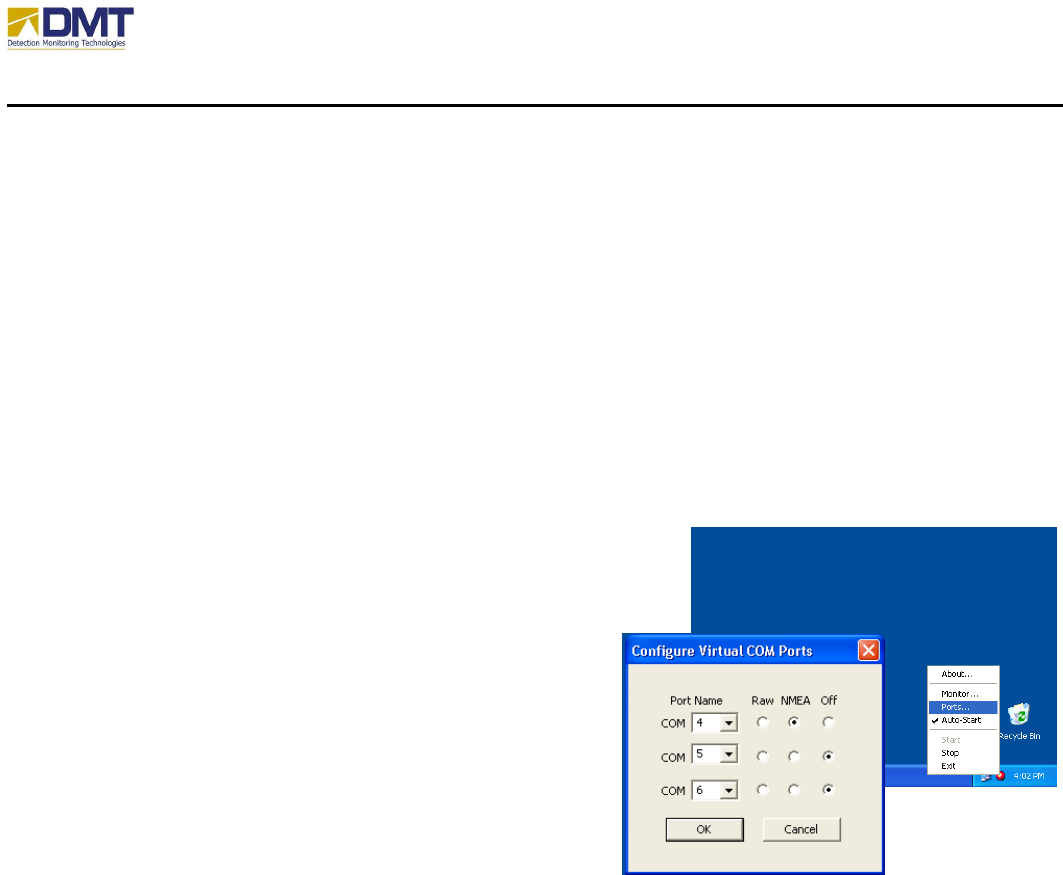
Locate the DeLorme icon (red ball) on your lower toolbar and
right-click to run the DeLorme Monitor function to verify the
GPS is operational. If data does not appear to be passing
to/from the GPS device, check the serial emulation tab
to be sure that at one of the available three ports are
enabled (this is the port that the AIMS software should
be directed to) and its NMEA tab is checked.
After installation is completed, you will need restart the
AIMS Radar server software and check the box “GPS”
on your Operation tab to begin using your GPS. The
GPS communication parameters are;
• Port. Note the Virtual COM Port (above)
• Baud Rate. 4800
• Data Bits. 8
• Parity. None
• Stop Bits. 1
4.4 Motor Software (SMI)
The elevation and azimuth motors are ‘smart’ motors and must be loaded with software to
properly function. The SMI Motor Terminal software is used to load the subroutines into the
motors at the factory on original configuration. The SMI Motor Terminal software is also loaded
onto each server CPU stack to support future maintenance, if required. The use and features of
this software may be referenced in a separate document, titled “Transferring Motor Codes”
(Instr_XferMotorCodes.pdf).

AIMS Fast-Scan Radar v3.22 Installation and Operations Manual
DMT, LLC • DMT-M200-311 • 08/2009
71
5 Client Software
As previously stated, although most all of the software parameters may be modified through the
server interface it is recommended that the normal use and modification of the system parameters
be performed from the client interface where more comprehensive error-checking and boundary
conditioning is performed to prevent the user from configuring an abnormal operating condition.
As configuration changes are made, the client interface sends sequences of instructions to the
server often momentarily stopping the current radar operation until the changes are completed.
5.1 Configurable Features
The table below provides a brief overview of the configurable parameters within the AIMS client
software.
Waveform
Generation
Signal
Processing
Motion
Management
Display /
Save Data
Other
PRF Rate A/D Sample Rate Mode
• Positional
• Velocity
Graphing
• FFT Data
• Line Graph
Network
• IP Addr
• Port
Pulse Width Range Bins
• No of bins
• Zero range bin
Scripts Segment Trunc.
No. of Pulses Filters
• Smoothing
• Matched
• Ramp
• Lobe Removal
o Main Lobe
o 2nd Lobe
o
3rd Lobe
Limits
• Azimuth
• Elevation
Saving IQ Data
• Autosave
• Save Detections
• Duration
Cameras
• Track to Alarm
• FOV
• Comm.
• Video Svr
• Offsets
Tracker
• AB Tracker
• Simple Tracker
•
Offsets Broadcast Interval BITE
• Check A/D Limits
Autoscan Save Settings
TX Frequency Tilt Compensation Restore
Zones Motion Compens. Start/Stop
Sensitivity
Speed Threshold Normalization
Basically, the configurable features entail;
• Defining the transmitted pulse (waveform generation)
• Selecting how to process the received signal (signal processing)

AIMS Fast-Scan Radar v3.22 Installation and Operations Manual
DMT, LLC • DMT-M200-311 • 08/2009
72
• Aiming the antenna (motion)
Additional configurable features include;
• Navigating cameras and viewing video streams
• Saving/replaying captured data
These configurable features are organized in an array of ‘tabs’ that provide user friendly check
boxes and option lists and are described in the following section, “User Interface Screens”.
AIMS Fast-Scan Radar v3.22 Installation and Operations Manual
DMT, LLC • DMT-M200-311 • 08/2009
73
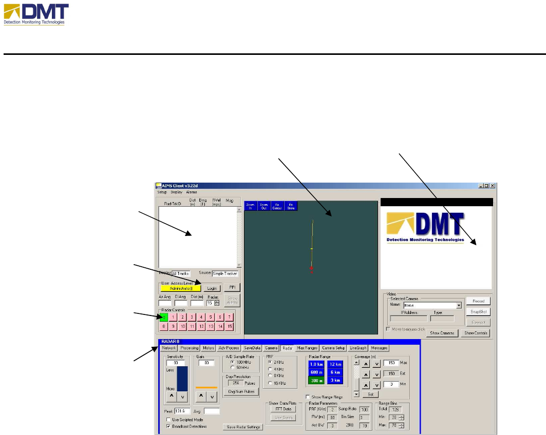
5.2 User Interface Screen Overview
The basic client screen appears like (picture below):
5.2.1 Login
In order to effect any changes to the display or configuration, a user must login; requiring both a
Username and Password (Username is logged in the activity audit trail). There are three levels
of authority; Administrator (complete rights), Supervisor () and Guard ().
Operators, supervisors and administrators must log in to the client before using. Pressing the
login button will cause a pop-up window to appear. The user must enter their login level
(operator, supervisor or administrator) and their password and optionally their name. The
button to the right will illuminate green for operators and yellow for administrators when login is
successful. At the end of a shift, the user should press the illuminated button. This logs them
out.
5.2.2 Select Radar Connection
Clicking on the Radar Controls Window will cause a pop-up window to appear. The window
will permit the user to add or delete a radar. Radars are assigned an index as added.
DETECTED
TRACKS
INFORMATION
PLAN POSITION
INDICATOR (PPI)
DISPLAY
CAMERA VIDEO
DISPLAY
CONFIGURATION
TABS
SELECT RADAR
CONNECTION
LOGIN
AIMS Fast-Scan Radar v3.22 Installation and Operations Manual
DMT, LLC • DMT-M200-311 • 08/2009
74
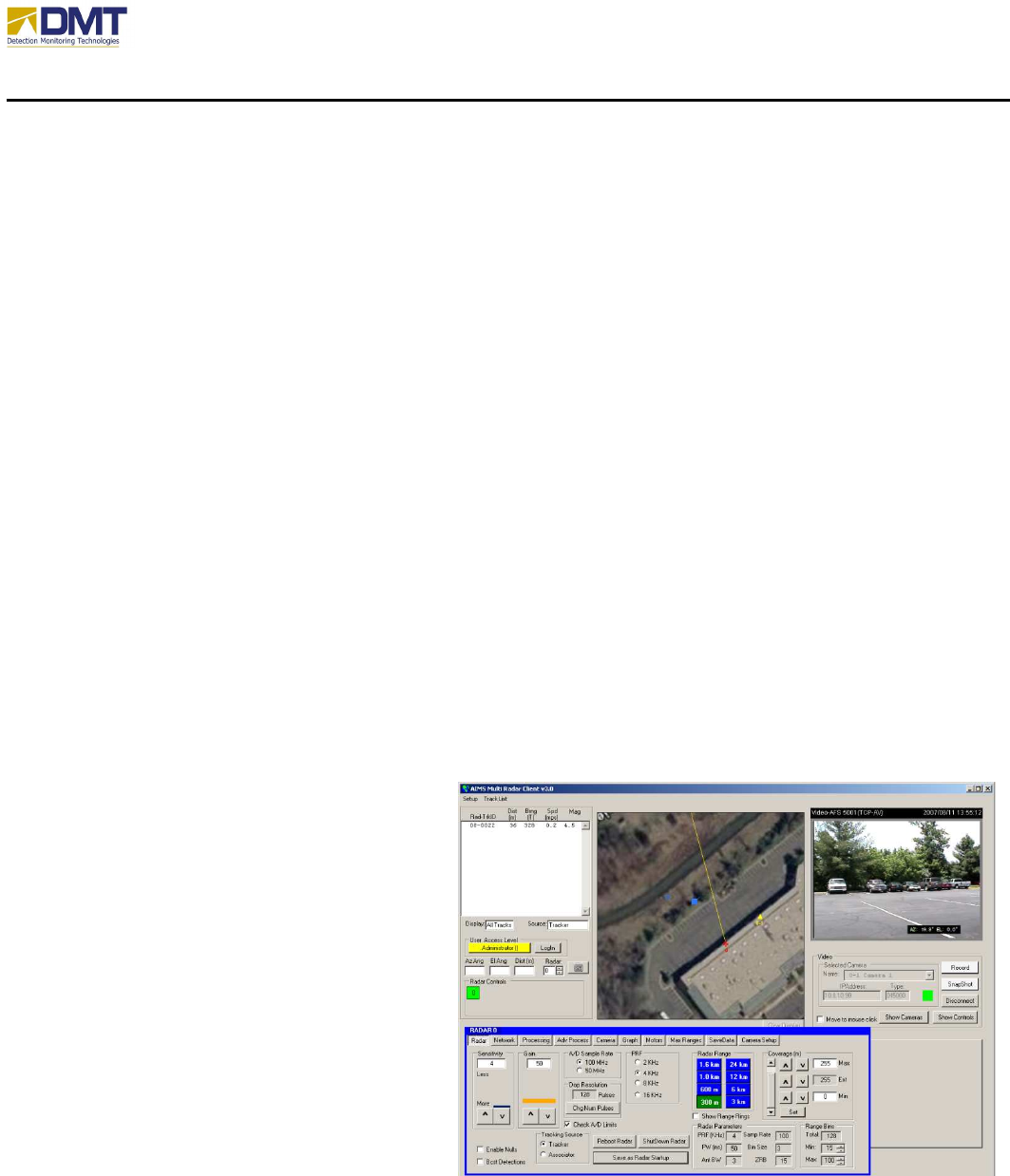
The client may connect to as many as 16 radar servers at one time. Adding a radar is as simple
as clicking on the Radar Controls area and select “Add a Radar.” This version can add up to 16
radar systems. Each new radar is given a button in the Radar Controls area, and the tab set
associated with that radar is given an index from 0 to 15. For instance, Error! Reference
source not found. shows 3 radar systems have been added and radar #1 parameter tab set is
open. Deleting a radar is also straightforward. Click on the Radar Controls area and select
“Delete a Radar. “ When a radar is deleted, the button is removed from the Radar Controls area.
All other radar indices remain the same, even if the radar being removed is not the last radar.
There is no reshuffling of the indices when a radar is removed. For example, if there are 3
radars (indexed 0, 1 and 2) and radar #1 is removed, the other 2 radars keep their index (0 and 2).
Cameras are added to the interface by assigning them to a given radar. The current version 3.22
permits 2 cameras to be controlled by a single radar server. Controlling more than one camera
requires that each of the cameras is addressable. Cameras that use serial communications (such
as RS-232/422/485) often set addresses using dip switches. Network cameras use IP addresses.
Cameras that are not addressable must have a serial port assigned to each camera, which limits
the number of cameras to 2. The radar server code has the appropriate port setup parameters if
this is required.
Only one video stream to be displayed at a time. The camera video being displayed is indicated
in the Video Server Control window and the camera’s position is illuminated as a triangle on the
PPI Display. (See Error! Reference source not found.).
5.2.3 Plan Position Indicator (PPI)
The Plan Position Indicator, or PPI,
provides the user a bird’s eye view of
where the detected activity is relative to
the radar locations. The PPI display plots
detection and track symbols over a digital
map. If no map exists, then a compass
rose (bearing markers and range rings)
are displayed. Radar locations are
indicated with red crosses; camera
locations as yellow triangles. Yellow
vectors from the camera or radar indicate
current look direction. Clicking on the
display will manually override slew-to-
cue (automated pointing of camera by
radar and point the camera.
AIMS Fast-Scan Radar v3.22 Installation and Operations Manual
DMT, LLC • DMT-M200-311 • 08/2009
75
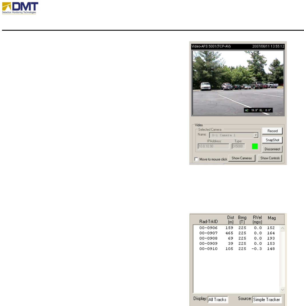
5.2.4 Camera Video Display
The video from any attached camera is shown in the video
display window. If there is no video or if there is a loss of
video, this window defaults to a white background with the
DMT logo.
Video Servers convert analog video streams to digital
streams and then pass them over a network. The video
server control allows the user to connect/disconnect and to
select the video feed shown in the Video Display Window.
The video server controls provides the TCP/IP address and
camera type. TCP/IP and camera types are set under the
Camera Setup Tab of the particular radar for which the
camera is linked.
If selected, “Move to mouse click” allows the user to
navigate the camera using the mouse. Simply by pointing to a location on the PPI display and
clicking the left button, the camera is instructed to change it elevation, azimuth and zoom to look
at the location selected.
5.2.5 Detected Tracks Information
Sustained detected activity that meets the guidelines for a
“track” are created and updated in this screen display area.
Tracks are identified by Track ID (Rad-TrkID), Distance
(Dist), Bearing (Brng), Radial Velocity (RVel), and
Magnitude (Mag). As new activity is detected the tracker
either updates an existing track or the foundation of a new
track is created. Tracks that do not have continued updates
eventually expire and are removed from this list.

AIMS Fast-Scan Radar v3.22 Installation and Operations Manual
DMT, LLC • DMT-M200-311 • 08/2009
76
5.3 Configuration Tabs
The initial values and selected options on the Configuration Tabs indicate the state of the AIMS
Radar once a network connection is established. Changes to the AIMS Radar parameters are
made by selecting (clicking) on option buttons and check boxes. Administrator privilege is
required to access most of the Setup Tab controls. Controls not available will be grayed out.
Caution: Users should not change values if they are unsure of the consequences. When
experimenting with new settings do NOT save the radar parameters as default until
performance has been verified.
The tabs provide access to the various features that may be changed to configure the system.
The tabs include;
• Network
• Processing
• Motors
• Adv Process
• SaveData
• Cameras
• Radar
• Camera Setup
• LineGraph
• Messages
The following subsections briefly discuss each tab and its parameter settings.
AIMS Fast-Scan Radar v3.22 Installation and Operations Manual
DMT, LLC • DMT-M200-311 • 08/2009
77
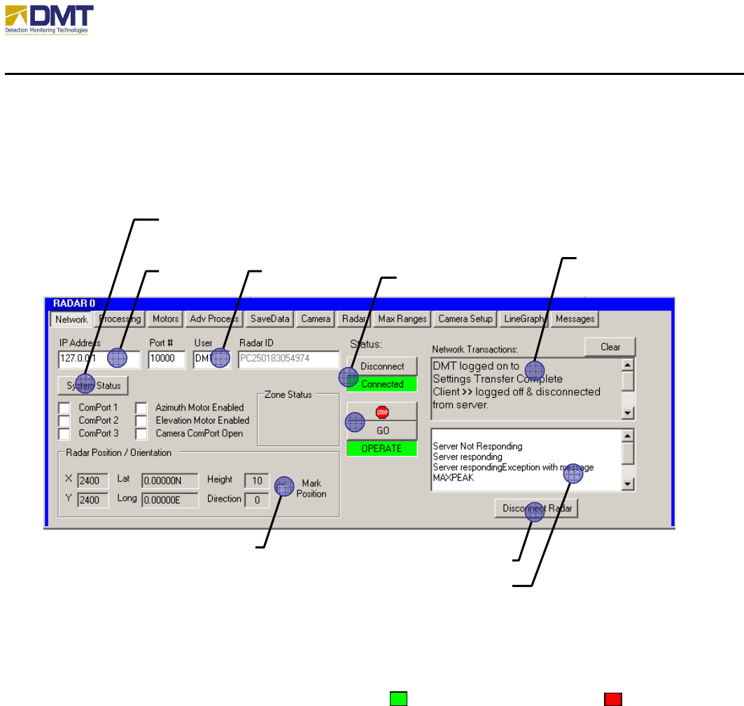
5.3.1 Network Tab
The Network Tab primary function is to provide the interface to connect and disconnect from the
currently selected radar server.
5.3.1.1 System Status
When selected, the System Status button forces the built-in-test function to verify the operational
status of the serial communications ports, azimuth/elevation motors, and camera ComPort. If
properly operating, the relevant box is filled green, . If not, the box is filled red, .
5.3.1.2 Radar Address
The IP Address and Port # of the currently selected radar must be properly entered here before
the client may connect to it.
5.3.1.3 User
A unique User name must be entered here prior to attempting to connect to the current radar
server. If another client is connected to the radar server under the same username, the server will
reject the connect request.
SYSTEM STATUS
RADAR
ADDRESS
NETWORK
TRANSACTIONS
WINDOW
USER CONNECT/DISCONNECT
RADAR
MARK
POSITION ‘HARD’ DISCONNECT
ERROR REPORTING WINDOW

AIMS Fast-Scan Radar v3.22 Installation and Operations Manual
DMT, LLC • DMT-M200-311 • 08/2009
78
5.3.1.4 Connect/Disconnect Radar
When selected the client request to connect/disconnect from the radar server. When connected,
only the disconnect button is active and when disconnected only the connect button is active.
When attempting to connect/disconnect, both buttons will temporarily be disabled until the
server verifies the change in status back to the client.
5.3.1.5 “Hard” Disconnect
Rarely used, this button forces the immediate termination of the client connection to the radar
and does not wait for verification from the server. This should only be used if there is an
unnatural suspension of the connection status.
5.3.1.6 Network Transactions Window
This windows displays all the major network transaction activity between the client and the
server. The window may be cleared by selecting the Clear button on the upper right hand corner
of the window.
5.3.1.7 Error Reporting Window
This window displays both error reporting and special messaging from the server to the client.
The window may be cleared by double clicking the mouse in the window space.
5.3.1.8 Mark Position
When selected, the mark position checkbox allows a user to position the icon of the current radar
on the map background by placing the mouse on the location for the radar and clicking the select
button. This function only works when a map has been placed unto the background of the
display. (for details on how to make maps for AIMS, refer to document “Map Making for
AIMS).
AIMS Fast-Scan Radar v3.22 Installation and Operations Manual
DMT, LLC • DMT-M200-311 • 08/2009
79
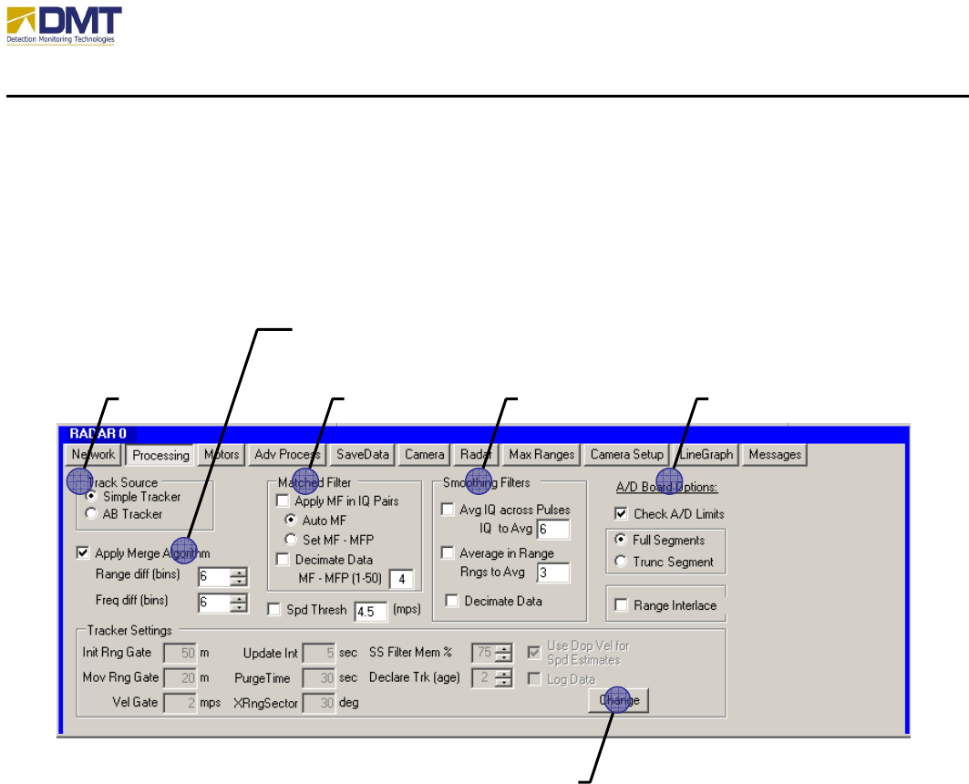
5.3.2 Processing
All of the items on the Processing Tab and Advanced Processing Tab are designed to reduce
signal from the environment (known as clutter), reject internal noise and false alarm generators,
and increase intruder signal strength.
5.3.2.1 Track Source
5.3.2.2 Merge Algorithm
5.3.2.3 Matched Filter
The Matched Filter is a digital signal processing technique that matches the receiver
characteristics to the transmitted characteristics. More directly, the pulse width and pulsed
shape are matched. Since the radar pulse for AIMS is very square (that’s a good thing), the
matched filter can be generated by simply matching receiver gate width to the transmitted pulse
width. This is accomplished by coherently summing the range bins until the sum equals the
pulse width. Since pulse width is in nanoseconds, it must be converted to meters (pw (meters) =
pw(nanoseconds) * 3E8). This implementation is sometimes referred to as a “boxcar” matched
filter. The result is improved range performance and clutter rejection. The size of the filter is a
function of the pulse width or length and can be set for Auto calculation (Auto MF) or set
manually (Set MF - MFP). Auto MF will allow the radar to calculate the appropriate number
CHANGE TRACKER SETTINGS
TRACK
SOURCE MATCHED
FILTER SMOOTHING
FILTERS A/D BOARD
OPTIONS
MERGE
ALGORITHM

AIMS Fast-Scan Radar v3.22 Installation and Operations Manual
DMT, LLC • DMT-M200-311 • 08/2009
80
of range bins needed to match the pulse width automatically. Set MF allows the user to override
the automated calculation. DMT have found that performance for the radar is often better when
the MF constant is a little lower than the value calculated by the Auto MF procedure. The MF
constant value is set and reported in the text box in the lower right corner of the Matched Filter
settings box. The matched filter routine is implemented before the FFT algorithm.
When the matched filter is applied to the data, it generates as a sliding window filter. For
instance, if the matched filter is set to 4, then the first application is range bin 1 = range bins
1+2+3+4, the second application is range bin 2 = 2+3+4+5, the third application is 3+4+5+6, and
so on. Decimate Data should be implemented as a method for speeding up processing. When
enabled, it applies the matched filter as stepped filter – not sliding. For example, if the matched
filter is set to 4, then the matched filter will be applied for range bin 1 = range bins 1+2+3+4,
then range bin 2 = range bins 5+6+7+8, range bin 3 = ranges bins 9+10+11+12, and so on. In
this example, the overall number of bins to be processed by the FFT will be one-fourth as many.
This would result in significantly faster processing, which in turn permits the radar to spin faster.
AIMS Fast-Scan Radar v3.22 Installation and Operations Manual
DMT, LLC • DMT-M200-311 • 08/2009
81
5.3.2.4 Smoothing Filters
5.3.2.5 A/D Board Options
5.3.2.6 Change Tracker Settings
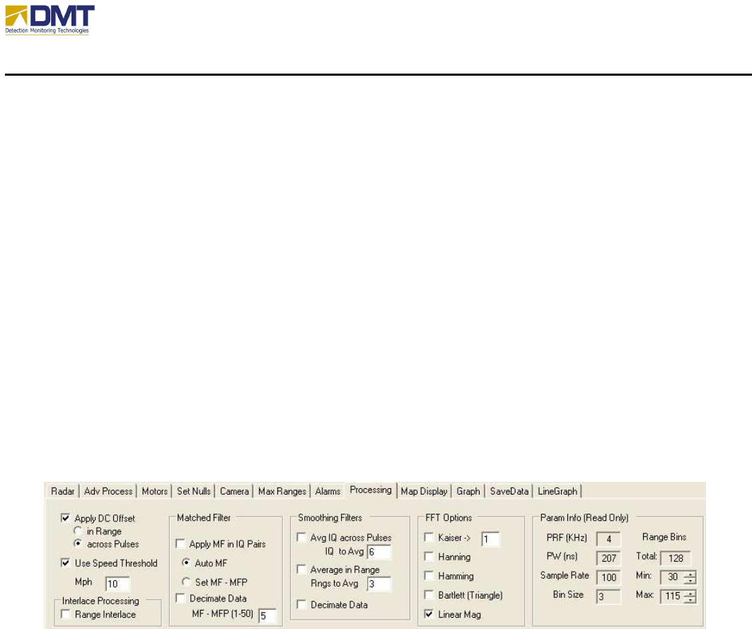
The Processing tab, Figure 1, contains options for the Matched Filter, FFT (Fast Fourier
Transform) processing, applying a DC Offset, and a Speed Threshold. The Advance Processing
Tab, Figure 19, contains Smoothing Filters, Ramp Functions, ClutterX options.
Apply DC Offset is an algorithm ensures that the In-phase and Quadrature (I/Q) channels of the
radar are well balanced and centered and 0 volts. Unbalanced and non-centered channels will
result processing sidelobes, which can generate false alarms. The in-Range option is a
traditional implementation of the algorithm, whereas, the across-Pulses is a better performing
implementation of the algorithm. DMT recommends that Apply DC Offset is always enabled
(checked) and across-Pulses is selected.
The Use Speed Threshold is an option that can be used to focus on targets of interest. The
threshold limits reported detections to targets traveling slower than the threshold speed; for
example only targets traveling 10mph or slower.
Figure 1 - Processing Options
Decimate Data does affect (reduces) the resolution of the system by elimination of the sliding
window. DMT recommends that Decimate Data be disabled for most sites and should only be
enabled when high rotation speed becomes critical.
AIMS Fast-Scan Radar v3.22 Installation and Operations Manual
DMT, LLC • DMT-M200-311 • 08/2009
82
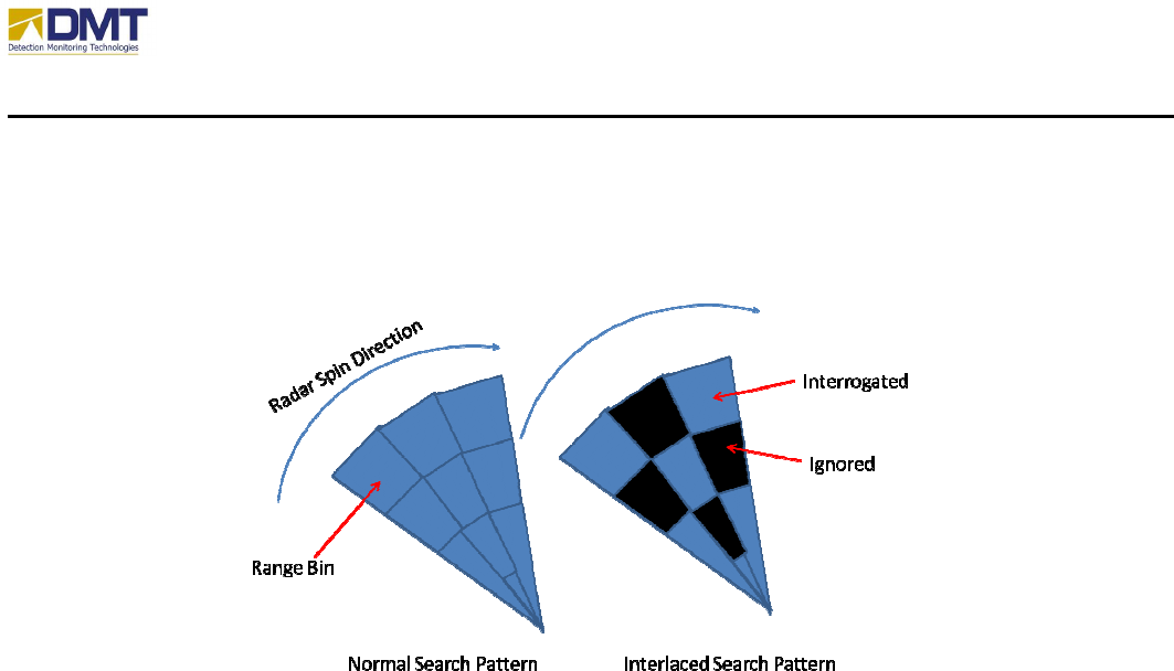
Range Interlacing is an algorithm that mimics the methods used by search and rescue teams to
quickly scan large areas in less time. DMT has added this algorithm to speed up search by
reducing the number of range bins that must be processed. Figure 8 illustrates the principle.
The process should only be used with rotation speed of the radar becomes critical.
Figure 2. Range Interlacing.
The Fast Fourier Transform (FFT) is used to generate Doppler signatures. Doppler is the
measure of frequency shift in a signal that is reflected off a moving object. An object moving
towards the radar results in a positive shift. A positive shift is a compression of the wavelength,
which translates to a resultant frequency higher than the transmitted frequency. An object
moving away from the radar results in a negative shift (a stretching of the wavelength), which
translates to a frequency lower than the transmitted frequency. Doppler can be converted to
object relative speed. That is, the Doppler can tell the user the speed of an object relative to the
radar. And the direction of the object relative to the radar can be instantly obtained by the sign
of the Doppler (positive means its heading toward the radar, negative means its heading away
from the radar). The FFT enables the radar calculate all Doppler frequencies for a given look
direction and for a single range bin. DMT’s software calculates thousands of FFT’s in a second.
To facilitate real-time operation, DMT has employed the fastest FFT algorithm available.
Since every look at an object is over a finite time, processing artifacts arise. One such artifact is
known as processing sidelobes. Sidelobes are normally displaced from the real Doppler
frequency, so the detection of these lobes can result in false Doppler readings. These sidelobes
have typically 20 times less power than the main lobe (real Doppler). So for the most part, these
sidelobes are not detected. For large objects, however, the integration gains from the FFT can
result in detectable sidelobes. If large objects are expected, then weighting of the raw radar data
can result in suppressed sidelobes. Kaiser, Hanning, Hamming, and Bartlett are weighting
algorithms. DMT does not normally invoke these algorithms when the radar is searching long
ranges. The reason is because there is a penalty in the true Doppler signal level when used.

AIMS Fast-Scan Radar v3.22 Installation and Operations Manual
DMT, LLC • DMT-M200-311 • 08/2009
83
The magnitude (strength) of radar signals is normally presented as either linear units (of voltage)
or in dB (decibels). Traditionally, dB is used in radar applications because it allows fine details
of small signals to be seen with clarity even when very large objects are present. However,
DMT uses Linear Mag (linear magnitude) for most site installations. Linear magnitude offers
finer control of threshold settings. The units for Sensitivity are set as by the selection of Linear
Mag. If checked, Sensitivity increments are in linear units. If not checked, then Sensitivity is
adjusted in dB units.
Param Info is a read-only section of the Processing Tab. The parameters listed in the box are
repeated elsewhere and are included as a reference.
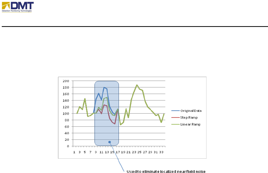
Additional Processing and Advanced Processing options shown in Figure 3 provide options to
apply Smoothing Filters, Ramp Functions, and ClutterX. The smoothing filters and ramp
functions are used to digitally lower signal strength over a given range swath. They are
particularly useful for reducing the affects of processing artifacts generated from very large
objects located at close ranges. Large objects at close ranges can reflect so much energy that it
saturates the radar at that range. Saturation can cause false target detection. Ramp functions
lower the signal strength to levels below alarm thresholds. The Beginning Range indicates the
first range bin for which the function is applied and the Ending Range indicates the final range
bin. The Ramp Percent represents that maximum percentage applied to the measured
magnitude (signal strength). So a Ramp Percent value of 30 means that the signal strength will
be reduced to 30% of its current value. Linear Ramp in Range means the reduction is applied
over a linear slope from 0 to Ramp Percent, which the above example is 30%. This linear slope
is applied over the Beginning Ranges to Ending Ranges. Step Ramp in Range means the
reduction is an equal percentage over the entire range swath defined (Beginning Range to Ending
Range). Clutter X allows for the removal of nuisance alarms around zero Doppler (very slow or
non moving objects). Clutter X (sometime referred to as a clutter notch), sets all values in and
around 0 Hertz = to the text box in the lower right hand corner. Appropriate settings for this text
box are usually 0 or negative numbers. [Note: A negative number lowers the plotted color of
the notch to black and thereby, is easier to see when looking at Doppler Plots. ] The number in
the upper left corner text box represents the number of Doppler bins (frequency slices) around 0
Hertz that are set. “0” in this text box equals to 0 Hertz only. “1” in this text box represents one
Doppler bin on either side of 0 Hertz is set. Commonly set values are 0 to 2. Clutter X is very
useful for removing the response from swaying trees, moving water, or windblown heavy brush.
Setting Clutter X too high can reduce the ability of detecting walking humans.
AIMS Fast-Scan Radar v3.22 Installation and Operations Manual
DMT, LLC • DMT-M200-311 • 08/2009
84
Figure 3 - Advanced Processing Options
AIMS Fast-Scan Radar v3.22 Installation and Operations Manual
DMT, LLC • DMT-M200-311 • 08/2009
85
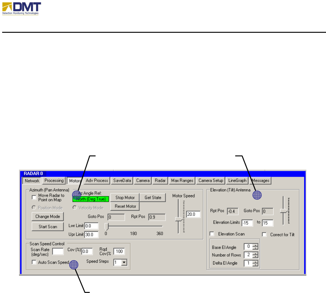
5.3.3 Motors
Antenna movement and position can be controlled using the commands on the Motors tab. This
is primarily intended for use during initial setup, sensor tuning, and troubleshooting. When in
position mode the radar can be moved to a specific location (azimuth and elevation) by clicking
on the map. To operate in this mode select the Move Radar to Point on Map check box and
simply click on the map. Caution: Verify the Azimuth motor is in the Position Mode before
selecting this option. Problems with the antenna motors are indicated by AIMS Server via a
message to the AIMS Client. The AIMS Client will display “Error” for the reported position (Rpt
Pos), Figure 10.
5.3.3.1 Azimuth Control
There are several commands available for working with the Azimuth motor. The primary
commands are Change Mode and Start/Stop Scan. Change Mode is used to transition the azimuth
motor between Position and Velocity modes. When in Position mode a sector scan can be
accomplished by setting lower and upper limits and clicking Start Scan. The button text will
change to Stop Scan and the azimuth motor will move between the lower (Lwr) limit and upper
(Upr) limit continuously until Stop Scan is clicked. Scan limits should be entered using negative
angles so that the minimum scan angle is always less than the maximum. For example, to scan
from 350 degrees to 20 degrees enter -10 to 20 for the minimum and maximum scan limits
respectively. The commands; Stop Motor, Get State, and Reset Motor were added for safety.
The Stop Motor command will send an immediate stop command to the motor. Once stopped the
SCAN SPEED CONTROL
ELEVATION CONTROL AZIMUTH CONTROL
AIMS Fast-Scan Radar v3.22 Installation and Operations Manual
DMT, LLC • DMT-M200-311 • 08/2009
86
Reset Motor command must be issued before any positioning or Change Mode commands can be
issued. The Reset Motor command starts the motor and sends it to the home or 0° position. Once
the motor has reached the home position it will automatically enter the position mode. The Get
State command will provides a status message that indicates the current mode of the motor;
position or velocity. The Position Mode and Velocity Mode options are intended to reflect the
status on the server only. The mode is changed by clicking on the Change Mode button. The
Change Mode button in the Azimuth antenna control toggles the Azimuth or Panning antenna
between the Constant Velocity mode (continuous spinning) and the Position mode. When
leaving the Constant Velocity mode the antenna will first return to the home position, 0°, before
entering the Position mode. Absolute position commands should not be issued until the antenna
has returned to the home position (Position Mode option is on). In position mode the slider can
also be used to position the antenna. As the slider is moved by clicking and holding the mouse
left button the angle is reported in the Goto Pos text box. When the slider is released, left mouse
button up, the go to position is transmitted to the AIMS Radar (server).
5.3.3.2 Elevation Control
The Elevation or Tilt motor remains in the Position mode. Adjustments in elevation (tilt) are
made using the slider bar or by clicking on the map (assuming the Move Radar to Point on Map
option is selected). To change the elevation using the slider bar click, hold and move the slider
to the desired angle and release. As the slider is moved the angle will be reflected in the Set El
Pos text box. When released this elevation position will be transmitted to the radar. As the
Antenna moves to a new location the angle will be reported in the Current El Pos text box.
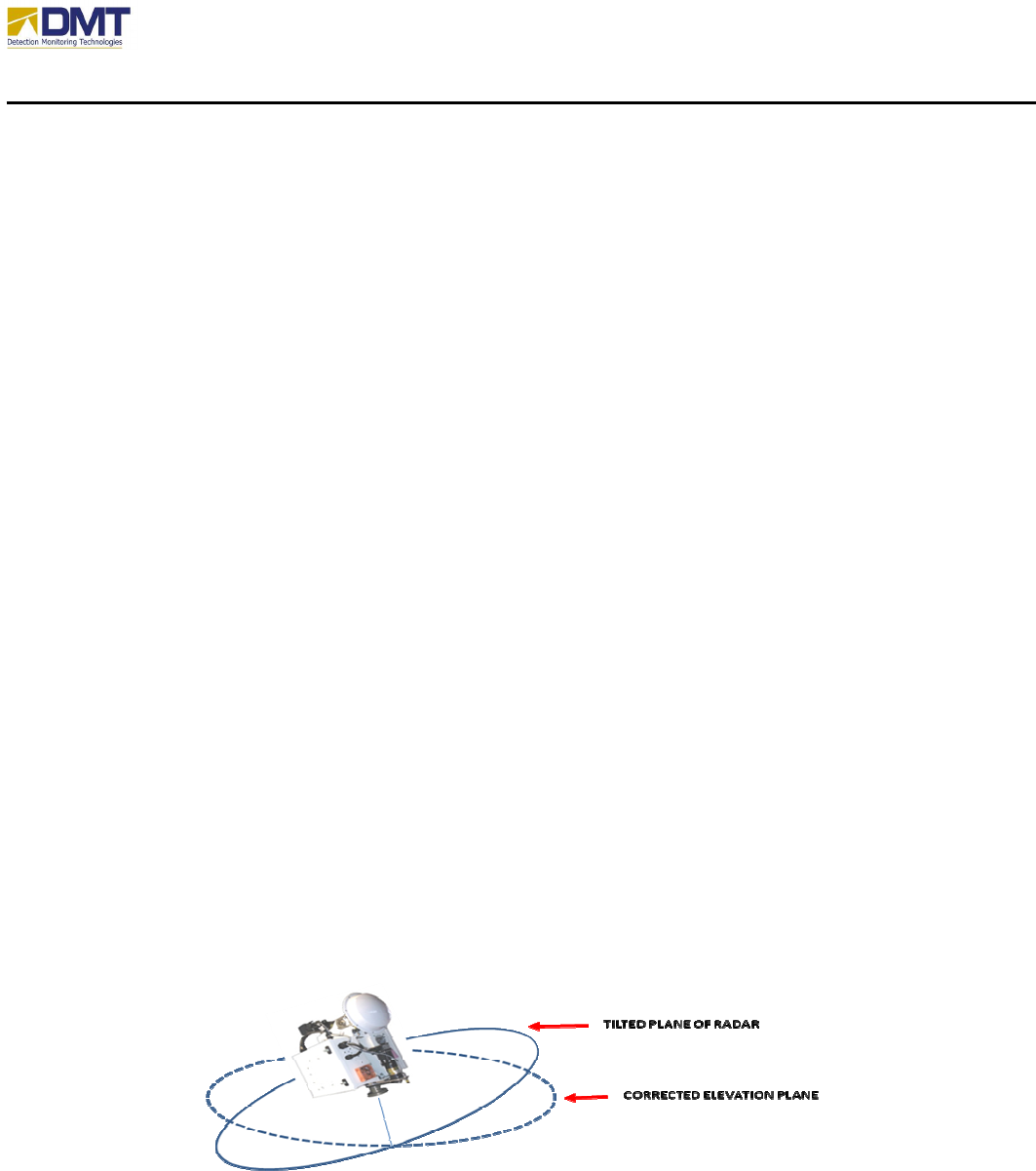
5.3.3.2.1 Tilt Compensation
The checkbox Correct for Radar Tilt enables the software to recalculate the horizon by creating
a new array of elevation settings based upon the tilt information provided by the compass (if
installed).
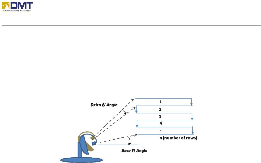
5.3.3.2.2 Elevation Scan
Elevation scan is used to search an area in the elevation domain where the area being search is
broader than the vertical beamwidth of the antenna. On the completion of each azimuth scan
AIMS Fast-Scan Radar v3.22 Installation and Operations Manual
DMT, LLC • DMT-M200-311 • 08/2009
87
range, the elevation is adjusted by the Delta Elevation Angle. Upon the completion of Number of
Rows, the direction of elevation scan is reversed (up-down-up-down…)
The elevation scan is defined by:
• Base Elevation Angle
• Number of Rows
• Delta Elevation Angle
5.3.3.3 Scan Speed Control
Auto Scan is a learning algorithm that tries to set the optimum motor speed dynamically to insure
the desired overlap in azimuth beam positions. It evaluates the min and max ranges for each
angle and the processing speed to determine the best speed setting. It works best for very wide
sector scans and 360° rotation. The Auto Scan control parameters include;
• Enable/disable Auto Scan Speed
• Required Coverage% (1-100%)
• Speed Steps
Also displayed in this area are;
• Actual Coverage %
• Current Scan Rate (deg/sec).
AIMS Fast-Scan Radar v3.22 Installation and Operations Manual
DMT, LLC • DMT-M200-311 • 08/2009
88
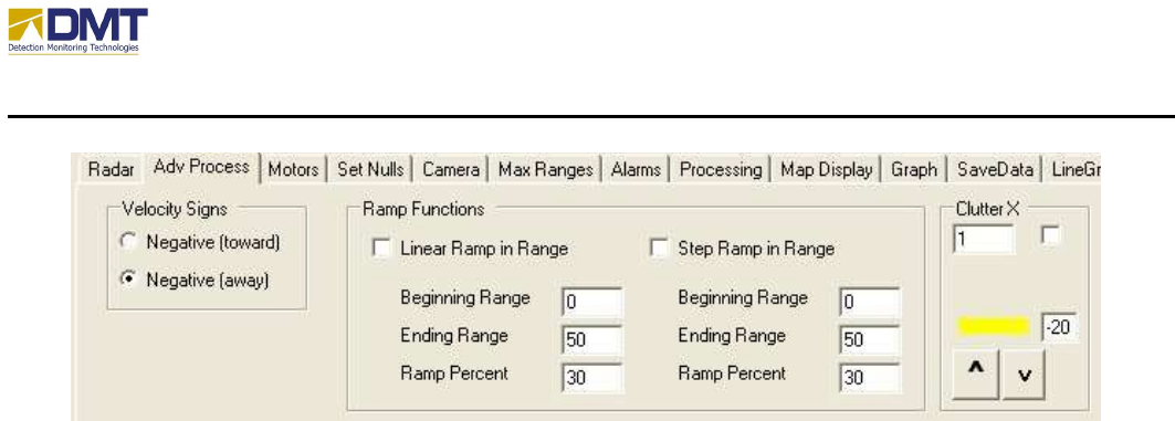
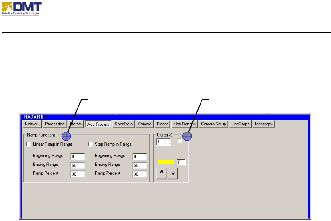
5.3.4 Adv Process
5.3.4.1 Ramp Functions
The ramp functions are used to digitally lower signal strength over a given range swath. They are
particularly useful for reducing the affects of processing artifacts generated from very large
objects located at close ranges. Large objects at close ranges can reflect so much energy that it
saturates the radar at that range. Saturation can cause false target detection.
The ramp function options include;
• Linear Ramp in Range
o Beginning Range.
o Ending Range
o Percent
• Step Ramp in Range.
o Beginning Range.
o Ending Range
o Percent
Ramp functions lower the signal strength to levels below alarm thresholds. The Beginning Range
indicates the first range bin for which the function is applied and the Ending Range indicates the
final range bin. The Ramp Percent represents that maximum percentage applied to the measured
magnitude (signal strength). So a Ramp Percent value of 30 means that the signal strength will
CLUTTER X RAMP FUNCTIONS
AIMS Fast-Scan Radar v3.22 Installation and Operations Manual
DMT, LLC • DMT-M200-311 • 08/2009
89
be reduced to 30% of its current value. Linear Ramp in Range means the reduction is applied
over a linear slope from 0 to Ramp Percent, which the above example is 30%. This linear slope is
applied over the Beginning Ranges to Ending Ranges. Step Ramp in Range means the reduction
is an equal percentage over the entire range swath defined (Beginning Range to Ending Range).
5.3.4.2 Clutter X
Main Lobe Removal (also referred to as Clutter X or clutter notch) allows for the removal of
nuisance alarms around zero Doppler (very slow or non moving objects) by setting all values in
and around 0 Hertz to the Mainlobe Value. Clutter X is very useful for removing the response
from swaying trees, moving water, or windblown heavy brush. Setting Clutter X too high can
reduce the ability of detecting walking humans.
The Main Lobe Removal options include;
• Remove Mainlobe. Enables the main lobe removal.
• Mainlobe Half-Width. The Mainlobe Half-Width represents the number of Doppler bins
(frequency slices) around 0 Hertz that are set. “0” in this text box equals to 0 Hertz only.
“1” in this text box represents one Doppler bin on either side of 0 Hertz is set. Commonly
set values are 0 to 2.
• Mainlobe Value. Appropriate settings for the Mainlobe Value are usually 0 or negative
numbers. (Note: A negative number lowers the plotted color of the notch to black and
thereby, is easier to see when looking at Doppler Plot). However, this value should be set
to zero when Autolobe is being used.
AIMS Fast-Scan Radar v3.22 Installation and Operations Manual
DMT, LLC • DMT-M200-311 • 08/2009
90
5.3.5 SaveData
The SaveData Tab is fairly self-explanatory as this tab is used to establish the conditions and
filename attributes that define how Raw IQ data files are saved.
5.3.5.1 Autosave Parameters
The Autosave settings include;
• Automatic Save
• Save Every x dwells.
• Range Limits.
• Azimuth Limits
5.3.5.2 Manual Save Parameters
The manual save settings include;
• Save Detections
• Start Save
o Immediate
o Timed.
Start Time
Duration

AIMS Fast-Scan Radar v3.22 Installation and Operations Manual
DMT, LLC • DMT-M200-311 • 08/2009
91
5.3.5.3 RawIQ File Saves
The file saving option allows raw IQ data to be stored on the local hard drive in the directory,
c:\Data. The file names used will be the system time preceded by the string value listed in the
text box, “File Name Base”. Enter the desired file name and check the Save RawIQ File box.
Uncheck the box to stop saving data files.
5.3.5.4 Other Parameters
The following values are annotations that are stored with the saved data file(s);
• Ant BW
o Az – Azimuth. The horizontal (or azimuth) beamwidth of the antenna.
o El – Elevation. The vertical (or elevation) beamwidth of the antenna.
• Radar Dir. The absolute bearing of the radar home position. If a digital compass is
installed, this information is updated on initialization or when Update HPR (Compass
Tab) is selected.
• Radar Lat. The geo-positional latitude coordinates of the radar installation. If a GPS is
installed, this information is periodically updated.
• Radar Long. The geo-positional longitude coordinates of the radar installation. If a GPS
is installed, this information is periodically updated.
AIMS Fast-Scan Radar v3.22 Installation and Operations Manual
DMT, LLC • DMT-M200-311 • 08/2009
92
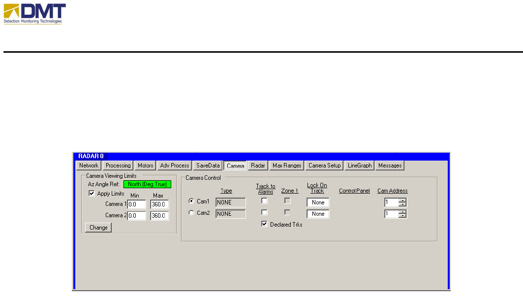
5.3.6 Cameras
AIMS Fast-Scan Radar v3.22 Installation and Operations Manual
DMT, LLC • DMT-M200-311 • 08/2009
93
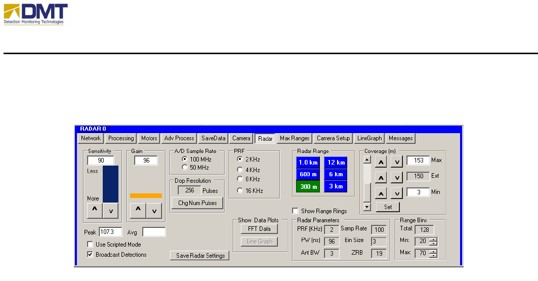
5.3.7 Radar

AIMS Fast-Scan Radar v3.22 Installation and Operations Manual
DMT, LLC • DMT-M200-311 • 08/2009
94
5.3.8 Max Ranges
AIMS Fast-Scan Radar v3.22 Installation and Operations Manual
DMT, LLC • DMT-M200-311 • 08/2009
95
5.3.9 Camera Setup
5.3.9.1 Camera Parameters
For each camera, the settings include;
• Name. Unique name to identify camera setup.
• Type. Camera type (Vicon, Pelco, Pelco-D… etc.). The type identifies the
communications protocol, configurable attributes and default communications
parameters. At current, the AIMS software supports the following types;
o None
o DI5000
o TASS
o QuicksetN2
o Vicon
o PelcoD. If Pelco is selected, the Turbo button is enabled to allow the user to
activate a fast slew.
o LRAD
o SentryII
o Vumii
• Connection
o SerialPort

AIMS Fast-Scan Radar v3.22 Installation and Operations Manual
DMT, LLC • DMT-M200-311 • 08/2009
96
COMM Port
BaudRate
DataBit
StopBit
Parity
Cam Address.
o TCPIP
IPAddress
Port
• Offsets.
o Look Offset – Az. This offset value defines the azimuth angle difference between
the home pins of the radar and the camera (see drawing below).
o Look Offset – El. This offset value defines the difference in degrees between the
camera look angle (at 0º elevation) and the horizon (up is positive).
o Position Offset – Az. This offset value defines the location (in degrees
clockwise) the camera is positioned relative to the radar home pin.
o Position Offset – Rng. This offset value defines the absolute distance the camera
is positioned relative to the radar (in meters).
o Height. This offset value defines the height the camera is positioned above the
ground.
• IP Address (Video). The IP address of the video codec/server that digitizes the camera’s
output video stream (usually inside the UCM).
• Camera Array. This selection is used to support a very specific application involving
four cameras installed at 90º angles and communicating on a single multidrop serial
communications line. More detail may be found in the DMT document, “Camera
Alignment and Operation Procedures for AIMS EA-System” (dated 1/23/2008).
AIMS Fast-Scan Radar v3.22 Installation and Operations Manual
DMT, LLC • DMT-M200-311 • 08/2009
97

AIMS Fast-Scan Radar v3.22 Installation and Operations Manual
DMT, LLC • DMT-M200-311 • 08/2009
98
5.3.9.2 Point to Mouse Click
This feature allows the user to quickly point any Camera attached to an AIMS Radar to a
geographic point on the Client’s PPI display. This action is performed by selecting the desired
camera for this command, and then clicking the mouse at the point on the PPI display. This
feature is discussed in more detail in the AIMS Client Manual.
5.3.9.3 Point to Radar Detection
Either or both Camera 1 and Camera 2 can be selected to point automatically at detections
reported by the controlling AIMS Radar. This selection can be made by checking the Track to
Alarms checkbox adjacent to the desired camera on the Client or on the Radar. When Track to
Alarms is selected for a camera, that camera will automatically point at each Radar detection as it
is declared.
The function is deactivated by un-checking the Track to Alarms checkbox.
5.3.9.4 AIMS Radar and Camera Alignment
The AIMS Radar software requires that several “alignment” parameters be determined for the
system configuration and entered into the Client and Radar control programs. This section
describes these parameters and illustrates the general procedure for determining their values.
These key alignment parameters are the Radar Direction (RadDir), the Look Offsets for each
camera (LookOffAz, LookOffEl), and the Position Offsets for each camera (PosOffAz,
PosOffRng). They are described briefly as follows:
• Radar Direction – The azimuth angle in degrees, measured positive clockwise, from True
North to the Radar’s look direction
5
at its home position. That is, the RadDir is the true
bearing of the Radar beam centerline at the Radar home position. This parameter is used
by the AIMS software to calculate the Latitude and Longitude values for detections and
other display symbols on the Client PPI display. If the RadDir is not entered properly in
the AIMS Client and Radar programs, then Latitude/Longitude values calculated by the
Radar will be incorrect.
• Look Offsets – These angles measure the difference (azimuth and elevation) between the
Radar look direction at its home position and the camera look direction at its home
5
The Radar look direction is the outward direction of the Radar beam centerline.
AIMS Fast-Scan Radar v3.22 Installation and Operations Manual
DMT, LLC • DMT-M200-311 • 08/2009
99
position. The LookOffAz is the azimuth angle in degrees, measured positive clockwise,
from the Radar to the camera. The LookOffEl is the elevation angle in degrees, measured
positive up, from horizontal to the camera look direction. These parameters are used by
the Radar software to calculate the proper pointing commands for the camera. Errors in
the LookOffAz and LookOffEl values will result in incorrect pointing commands sent to
the camera.
• Position Offsets – These offsets account for a camera being located at a different position
than the AIMS Radar. The PosOffAz is the azimuth angle (measured positive clockwise)
from the Radar look direction at its home position to the point where the camera is
located. The PosOffRng is the range in meters from the Radar to the camera position.
Errors in these values will result in incorrect pointing commands sent to the camera.
The AIMS control software will utilize the alignment parameters defined above to generate
correct geographic positions (Latitude and Longitude) and to generate the correct azimuth and
elevation angles for commanding cameras to point at radar detections and at geographic points
on the AIMS Client PPI display.
The next sections will describe how to measure the various alignment parameters using this
general diagram.
5.3.9.5 Radar Direction Measurement
The Radar Direction (RadDir) parameter measures the geographic
orientation of the Radar. The figure below shows the plan view with
the radome removed, the base plate exposed, and the AIMS Radar
visible and located at its home position.
The Radar Direction is the angle in degrees between True North and the
Radar home position. It is recommended that this direction be marked
on the base plate so that it can be seen once the radome is replaced.
AIMS Fast-Scan Radar v3.22 Installation and Operations Manual
DMT, LLC • DMT-M200-311 • 08/2009
100
5.3.9.6 Camera Look Offsets
The figure at right illustrates the geometry for measuring the
Look Offset azimuth (LookOffAz) for a camera mounted on
top of the AIMS radome, with the Radar and the camera home
positions indicated.
The Look Offset elevation (LookOffEl) should also be set to
“0.” Note that the Radar orientation is expected to be level.
AIMS Fast-Scan Radar v3.22 Installation and Operations Manual
DMT, LLC • DMT-M200-311 • 08/2009
101
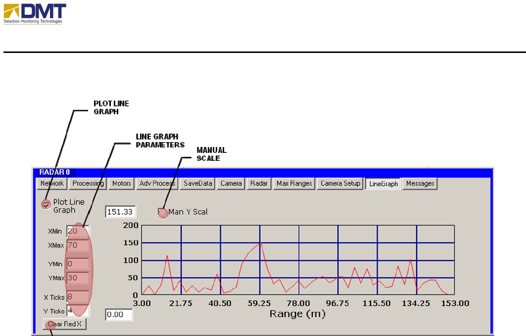
5.3.10 LineGraph
The Plot Line Graph option on the Line Graph tab plots the maximum Doppler return for each
range. This is essentially a two dimensional representation of the FFT data. When selected, a
line plot will be updated with each processing cycle of the AIMS Radar. The divisions on the
plot can be changed by entering new values for the number of X or Y ticks. The values for the Y
Axis, Ymin and Ymax can be set by selecting the Man Y Scale option. It is recommended that
the Plot Line Graph option be disabled when changing the values for graphing.
The Line Graph parameters include;
• YMin. When Man Y Scale is enabled for Line Graph, this parameter sets the minimum
Y-axis value.
• YMax. When Man Y Scale is enabled for Line Graph, this parameter sets the maximum
Y-axis value.
• YTicks. When plotting Line Graph, this parameter sets the number of Y-axis gradient
lines.
• XTicks. When plotting Line Graph, this parameter sets the number of X-axis gradient
lines.
When displaying a lot of graphics in real-time the Windows environment will sometimes get
hung up and fail to properly refresh, showing a red X in the graphic window. The Clear Red X
button clears those resources and allows the graphic display to recover.
AIMS Fast-Scan Radar v3.22 Installation and Operations Manual
DMT, LLC • DMT-M200-311 • 08/2009
102
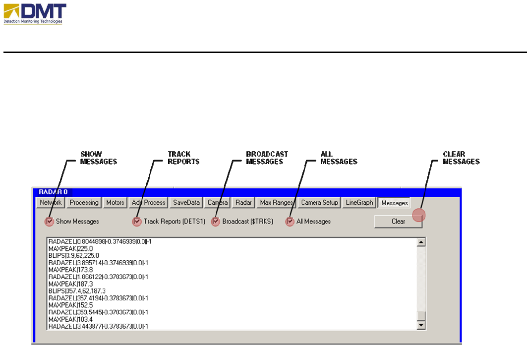
5.3.11 Messages
This tab is used to visually monitor the reported traffic between the Radar Server and Client
software.
The user may elect to see the Track Reports, Broadcast Messages, All Messages or none. The
Clear Messages button is used to erase any previous messages from the screen display.

AIMS Fast-Scan Radar v3.22 Installation and Operations Manual
DMT, LLC • DMT-M200-311 • 08/2009
103
5.3.11.1 Processing Parameters
The Go and Stop buttons are used to start and stop the radar. Clicking the Go button sets a flag
and puts the radar into the OperateLoop. Once entered the loop is continuous. Pressing the Stop
button sets another flag that prevents the Operate subroutine from being called. The Operate
loop is where the digitized data is processed.
Several check box options are available
• Print to GUI. The detection data is printed in the box on the Detection Tab.
• Replay Data/Folder. Prompts the user to select files for plotting. This is a diagnostic
mode and should only be selected when the radar is stopped. To change the list of
selected files the check box should be cleared and then checked again. To replay all files
in a folder, check the folder checkbox.
• Scripted Mode. Checking this box results in values for the min and max ranges and the
elevation angle being read from a file. The values stored are indexed by the azimuth
angle and are intended to allow the radar to follow an outline created for an area of
interest (configurable only through the Client interface).
5.3.11.2 Auto Scan Control
Auto Scan is a learning algorithm that tries to set the optimum motor speed dynamically to insure
the desired overlap in azimuth beam positions. It evaluates the min and max ranges for each
angle and the processing speed to determine the best speed setting. It works best for very wide
sector scans and 360° rotation. The Auto Scan control parameters include;
• Enable/disable Auto Scan Speed
• Required Coverage% (1-100%)
• Speed Steps
Also displayed in this area are;
• Actual Coverage %
• Current Scan Rate (deg/sec).
5.3.11.3 Camera Parameters
For both Camera 1 and 2, the camera tracking settings include;
AIMS Fast-Scan Radar v3.22 Installation and Operations Manual
DMT, LLC • DMT-M200-311 • 08/2009
104
• Track to Alarm. Checking this box will enable slew-to-cue tracking of the camera to
alarm detections.
• Zone 1. If Track to Alarm has been checked, the checking of this box restricts the
tracking to alarms detected within Zone 1 only.
• Camera FOV Settings. The minimum and maximum field of view (FOV) settings are
used to limit camera tracking to range of coverage for each camera (after entering new
values in text boxes click SetAngs to load values in system).
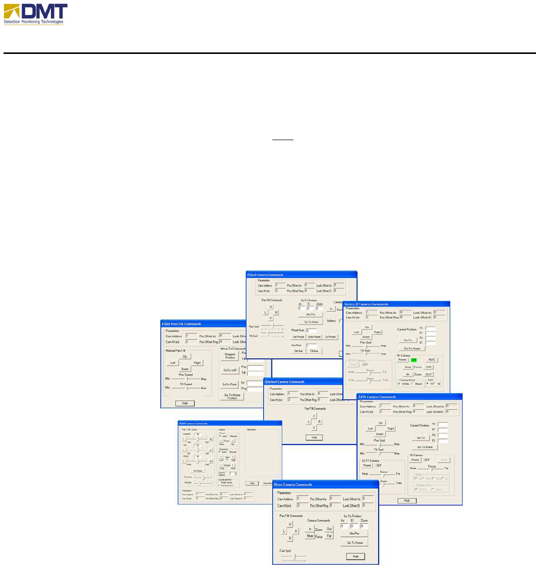
If a camera had been setup there would also appear another button Show Cmds immediately to
the right of the Zone1 checkbox. Selecting this feature brings up a new window containing
camera management tools uniquely setup for each camera Type (see Camera Setup tab). Some
example camera management screens appear below.
5.3.11.4 System Status
Selecting this button engages a built-in test function that verifies communications with the serial
communication ports 1, 2 and 3, interrogates both the azimuth and elevation motors and verifies
no other errors have been reported.

AIMS Fast-Scan Radar v3.22 Installation and Operations Manual
DMT, LLC • DMT-M200-311 • 08/2009
105
5.3.11.5 Restore Factory Settings
Used when all other efforts have failed to restore the operational state of the equipment! Before
the equipment has left the DMT factory, during the final testing process, a factory settings file is
created (“FactorySettings.txt”). Like the Saved Settings file (“SrvrSetMR.txt”), the Factory
Settings file is used to restore the equipment to a known operational state. Please do not alter
this file.

AIMS Fast-Scan Radar v3.22 Installation and Operations Manual
DMT, LLC • DMT-M200-311 • 08/2009
106
6
Troubleshooting
6.1 No Connection to the AIMS Server.
If the AIMS client is not connected follow the instructions listed in Error! Reference source
not found.. Be sure that the correct IP address and Port number are entered on the Network tab.
If all settings are correct and no connection can be established;
1. Open a command window and use ping to check the communication link to the AIMS
Server, enter ‘Ping’ followed by a space and the IP address for the server.
2. Check the IP configuration of the client computer by typing “ipconfig” in the command
window. The client (or local) machine running the AIMS Client software should have an
IP address similar to AIMS Server.
3. If the local machine and radar can be pinged, use Remote Desktop to connect to the
Radar. Be sure that the AIMS Server application is running. Start the application if it is
not.
4. If no communication to the Radar is possible, but local PC appears to be functioning
normally, you may need to cycle the power to the Radar (a last resort).
6.2 The AIMS Server crashes.
This may happen if the AIMS Server application was restarted and there are erroneous values in
the default parameter set file.
1. Connect to the AIMS Server using Remote Desktop.
2. Delete the SrvrSet.txt file located in the DMTLLC folder in the root directory (normally
c:\DMTLLC\SrvrSet.txt)
3. Restart the application.
6.3 I’m getting too many False Alarms
This happens when one or more parameters have been set incorrectly, if the environment has
changed significantly since installing the system, or if a man-made or object in nature begins to
suddenly move dramatically.
There are several ways to control False Alarms:
– Set Range properly (u
us
se
e Scripted Mode when possible)
– Set Gain properly (Default set at installation)
– Set Sensitivity (Default set at installation)
– Set Clutter Cancellation (Clutter X):
• Used to create a clutter notch (eliminates frequencies around 0 hertz)
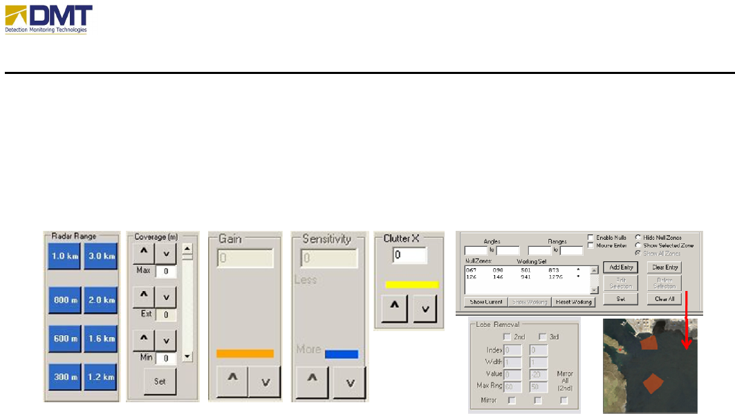
AIMS Fast-Scan Radar v3.22 Installation and Operations Manual
DMT, LLC • DMT-M200-311 • 08/2009
107
• Default = 1, most commonly used values = 0, 1 or 2. Severe clutter values = 3 or
higher.
– Set Null Cells (discussed in user manuals), Ramps or Steps
– Use Null Doppler Slices
The above mentioned items have been discussed in previous sections of this paper. Figure
shows what these controls look like.
Figure 13. False Alarm Reduction Controls
6.4 I am not detecting as far as I would like.
For most occasions, the inability of the radar to detect an intruder is due to one or more settings
of the radar. For instance, the intruder may be visible in a camera but is not detected because
the maximum range setting is shorter than the current range of the intruder. The intruder may be
inside a zone of no interest (a null zone, for instance). Remember that range is set using the
Radar Range buttons found on the Radar Tab or through the Scripted Mode (described in earlier
modes).
Detection range performance for a given intruder is a function of:
• RCS (radar cross section)
• Output Power of the radar
• Antenna Gain
• Environmental Losses or obstruction.
RCS is out of the control of the user. It is the “size” of the object as viewed by the radar. The
wavelength of the radar, the reflectivity of that object, shape of the object, orientation and the
size of the object affect its RCS. Units are given in square meters (sm) or dBsm. A walking
human is taken to be 1 square meter or 0 dbsm by DMT.
The AIMS radar systems are ordered for a given detection range for humans. A 1.5 km AIMS
radar means it should be able to detect the average walking human up to about 1.5 km. Output
power and antenna gain are set by the factory for these ranges. So if you have purchased a 1.5
km system, the power amplifiers used to generate the pulsed energy and the antenna size and
shape have been specified to give you this performance. So if you have purchased a 1.5 km
radar, you will not see a person at 3 kms – even if you have selected 3 km on the user
interface. In addition, if the person is crawling or if the intruder is smaller than a human, the

AIMS Fast-Scan Radar v3.22 Installation and Operations Manual
DMT, LLC • DMT-M200-311 • 08/2009
108
detection range will be less than the maximum rated performance. So for our example, a
crawling human will be detected at ranges less than 1.5 km for a 1.5 km radar.
If the person is walking behind a building or wall, the radar will not detect that object. In
addition, a person partially obstructed will have a lower RCS and will also be detected at shorter
ranges than a walking human. An example of this is thick vegetation. If a person walks in
thick brush up to his/her waist, then the maximum detection range for this person is likely to be
reduced to 75 to 80% of the range of a fully illuminated person.
There are 4 methods, however, for increasing the detection range of the radar:
- Increasing the GAIN setting of the radar;
- Decreasing the SENSITIVITY setting of the radar;
- Increasing the DOP RESOLUTION setting of the radar;
- Slowing the spin rate of the radar.
With the exception of the spin rate, these controls are all found on the Radar Tab.
Increasing Gain actually increases the transmitted pulsewidth of the radar. The greater the
pulsewidth, the greater the average power output of the radar. This, in turn, will increase the
detection range against all intruders.
Decreasing the Sensitivity setting actually lowers the threshold of the radar. Lowering the
threshold of the radar will permit the weaker signals from distance objects to be detected at
further ranges. However, lowering the Sensitivity control too low will cause more false alarms
from near-in objects.
Increasing the Dop Resolution control value actually increases the number of pulses integrated
by the radar. The more integrated pulses, the greater the effective signal strength for coherent
objects (like people and cars). The greater the effective signal strength, the longer the detection
range. Unfortunately, the price is paid by longer processing times. This often translates to
slower spin rates.
Slowing the spin rate of the radar enables more energy to return to the radar receiver from the
“sweet spot” of the antenna. The “sweet spot” (or inner 1-dB of the antenna’s main lobe)
supplies the greatest amount of available power on the object of interest. There is a point of
diminishing returns. Spinning the radar too slow will provide no additional performance boosts
and can cause the radar to miss seeing an intruder due to the low revisit rate. Currently, the spin
rate can only be set on the radar server code.
6.5 How do I use Sensitivity and Gain?
The Sensitivity control on the Radar Tab is a measure of the required signal strength needed to
declare an alarm. The AIMS radar calculates the average signal strength using the outer cell
slices of the Doppler Spectrum for every range bin. This value plus the Sensitivity setting value
is compared to the peak Doppler response for every range bin. This procedure reduces false
alarms by ensuring that the threshold is applied consistently above the average signal for every
range bin. Figure illustrates the point. The red curve is the average Doppler spectra level versus
range. The blue curve adds the threshold (Sensitivity) value to the red curve. It is this blue
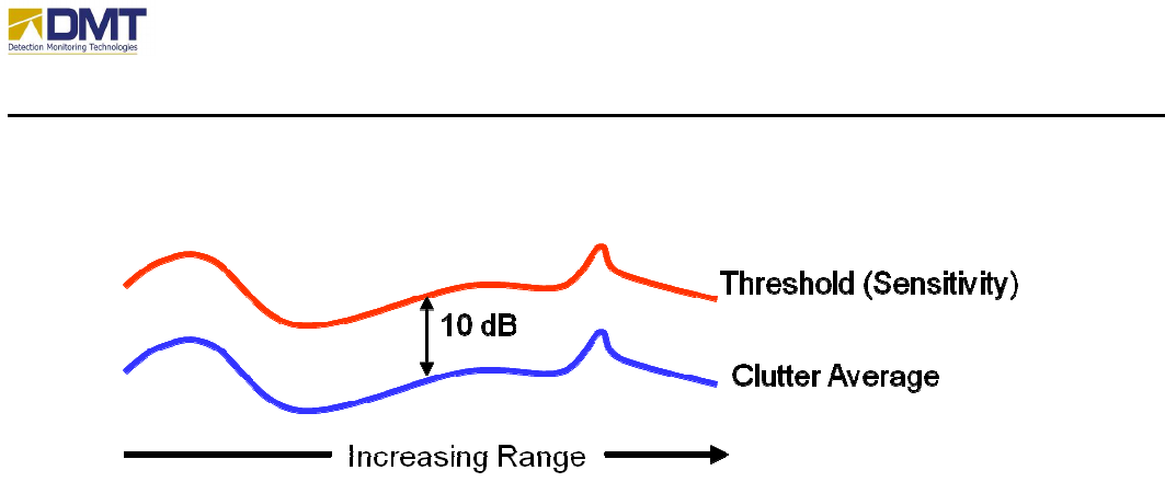
AIMS Fast-Scan Radar v3.22 Installation and Operations Manual
DMT, LLC • DMT-M200-311 • 08/2009
109
curve level that must be crossed before a detection is declared. Of course this is the first of
many steps used in validating the detection is a real target.
Figure 14. Threshold Setting
Gain is used to increase the average power of the radar. The value displayed in the textbox is the
actual pulse width in nanoseconds (10
-9
seconds). Typical values of gain are normally set to
between 100 and 300 nanoseconds. When Gain increments, the values are the valid pulses
currently wired in the radar’s waveform generator board. Many more values are available, but
must be specified upon request. DMT does not include all of the possible pulse widths settings
because it is not particularly useful. A 101 nanosecond pulse, for instance, does not really
provide measurable performance gain over a 100 nanosecond pulse. So DMT has provided only
significant jumps in performance in the Gain control.