Digi 50M1699 WLAN Module User Manual CC Wi i MX51 HRM
Digi International Inc WLAN Module CC Wi i MX51 HRM
Digi >
Contents
- 1. User Manual Part1
- 2. User Manual Part2
- 3. User Manual Part3
- 4. User Manual Part4
- 5. User Manual
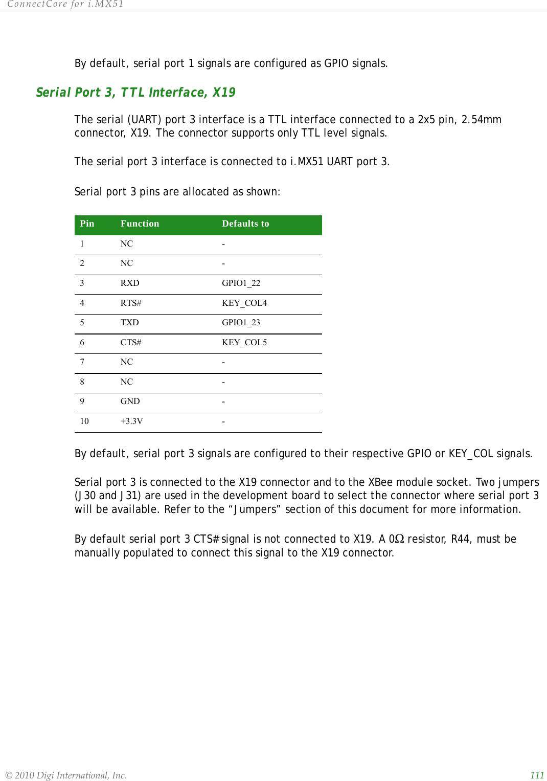
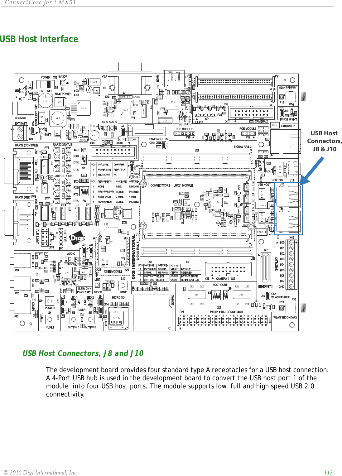
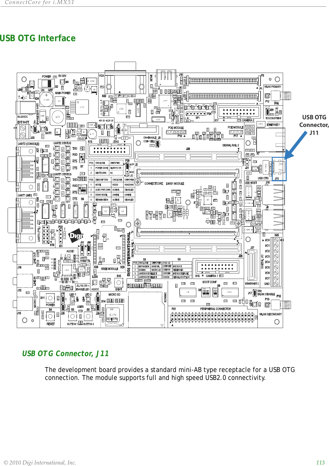
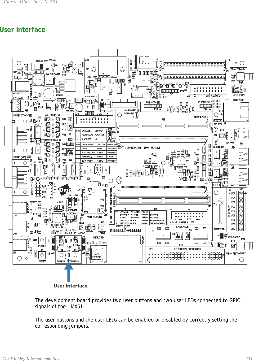
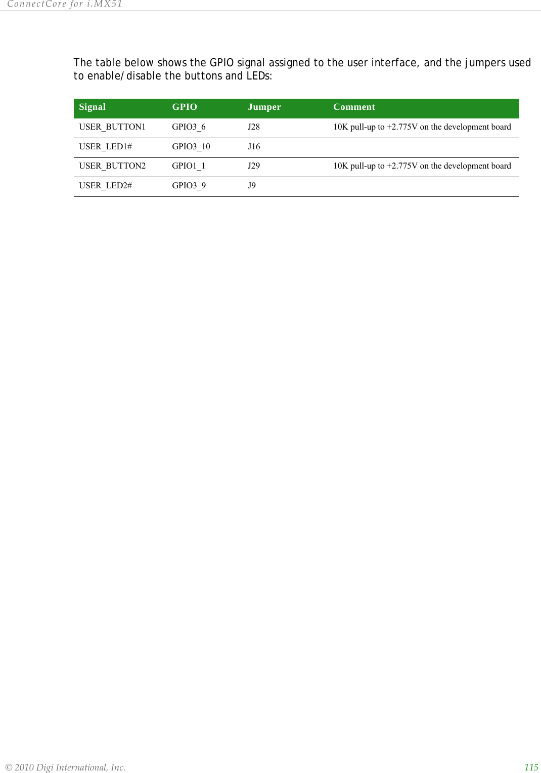
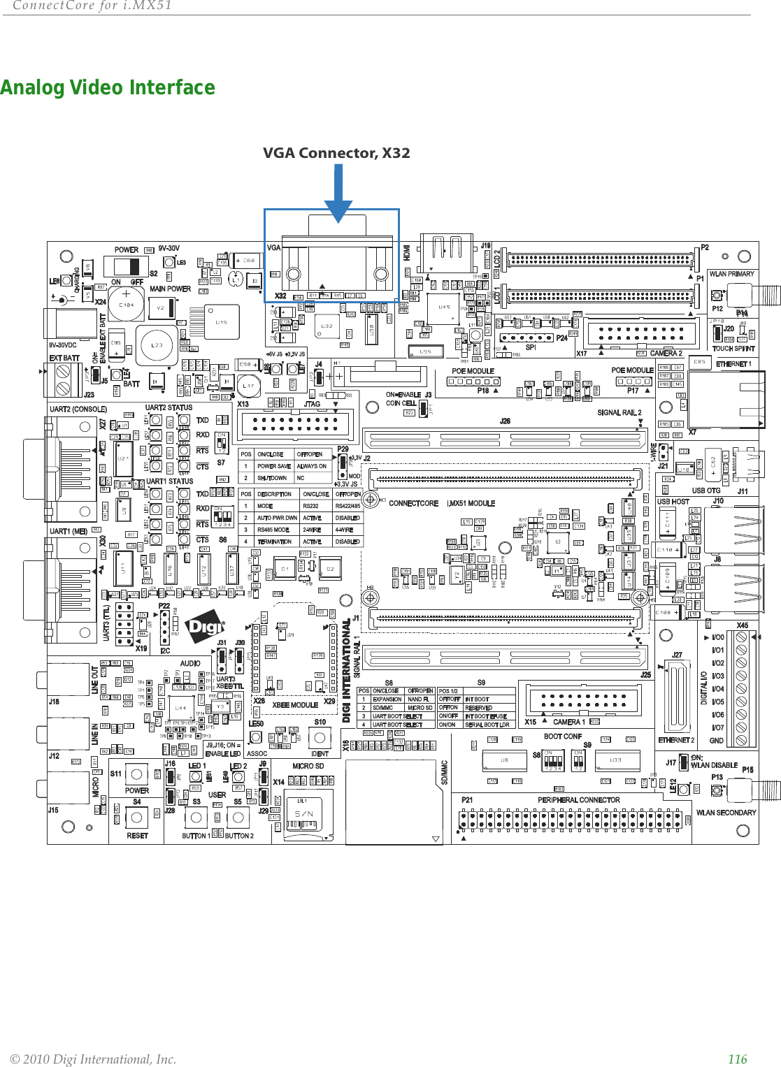
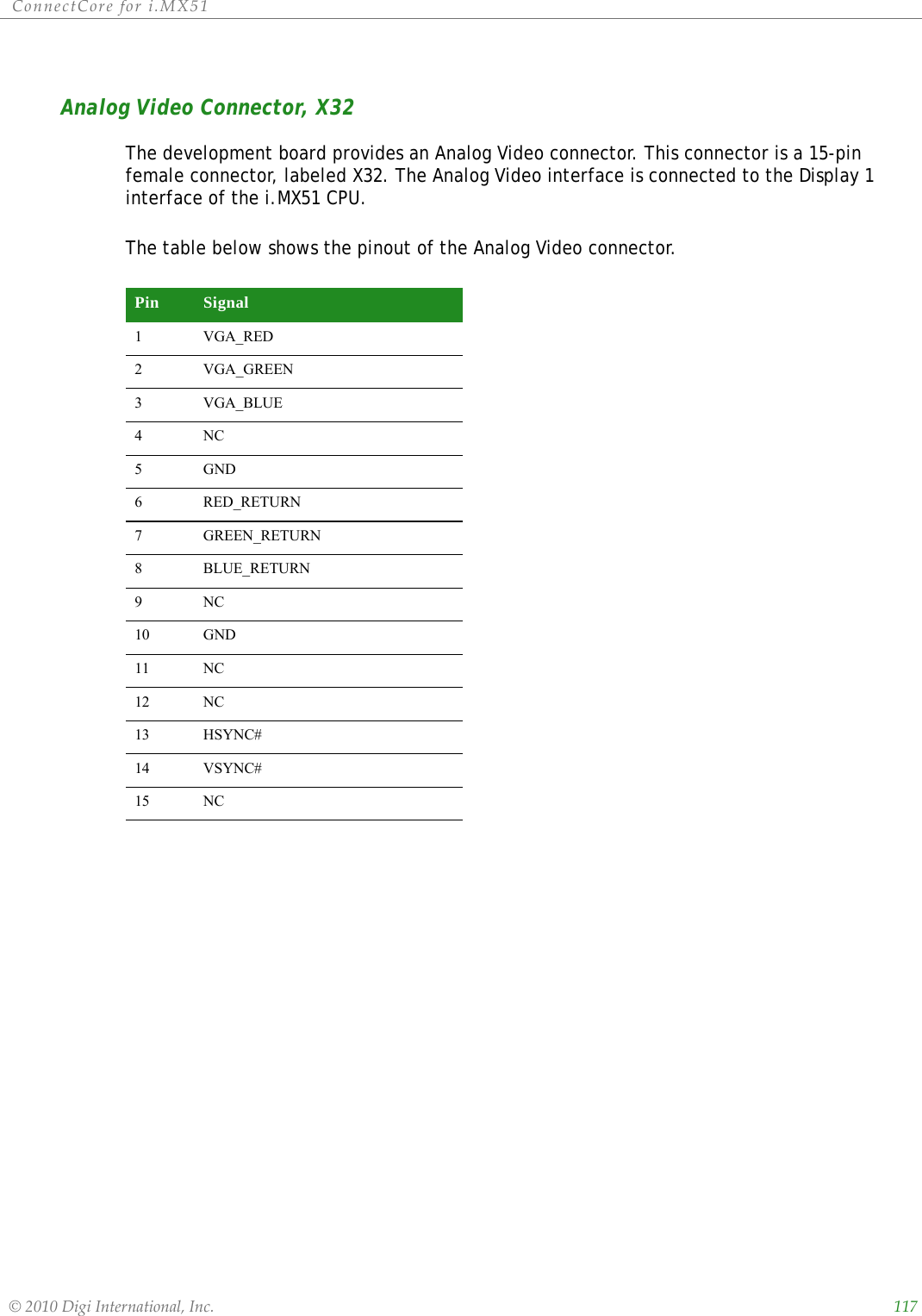
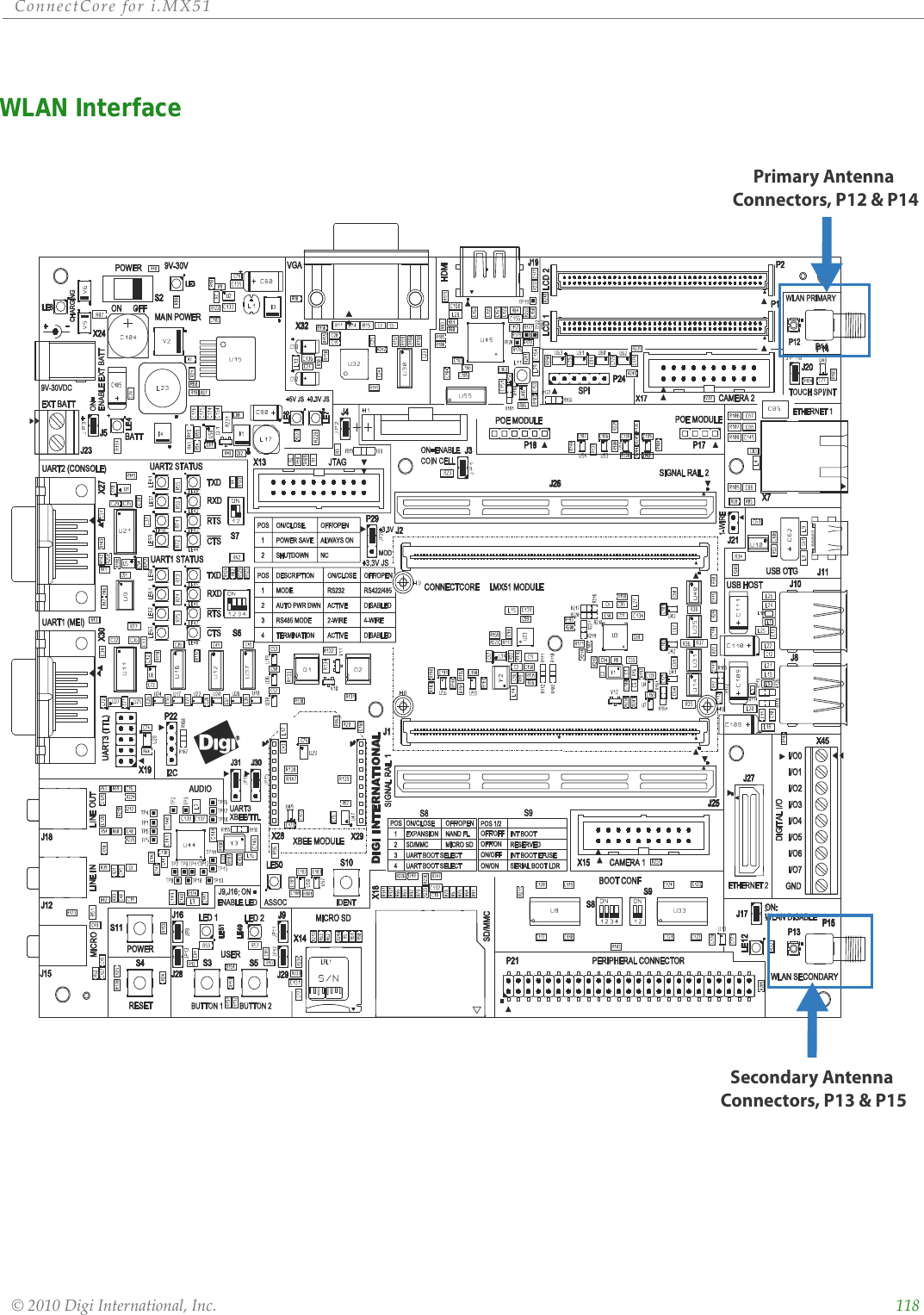
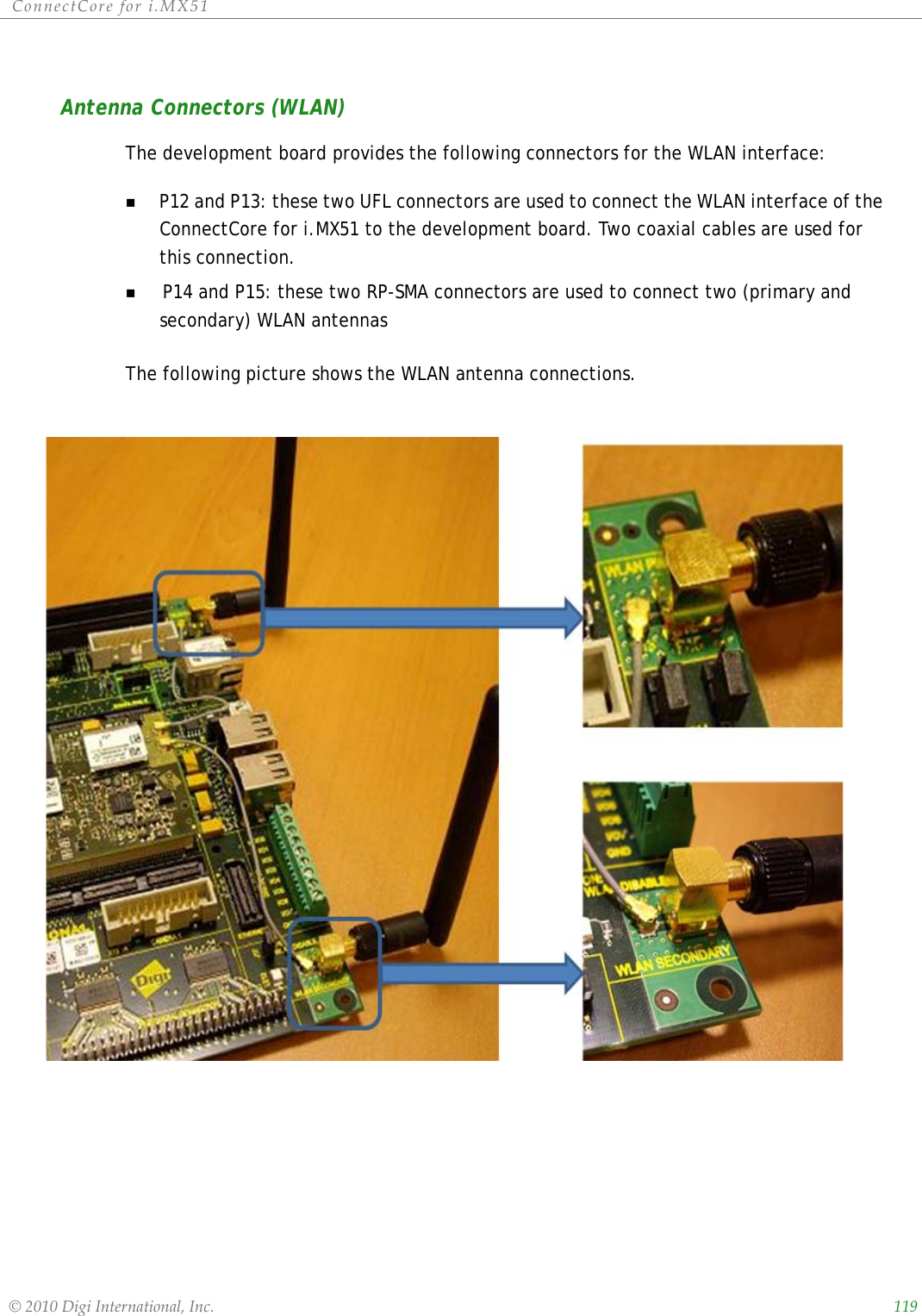
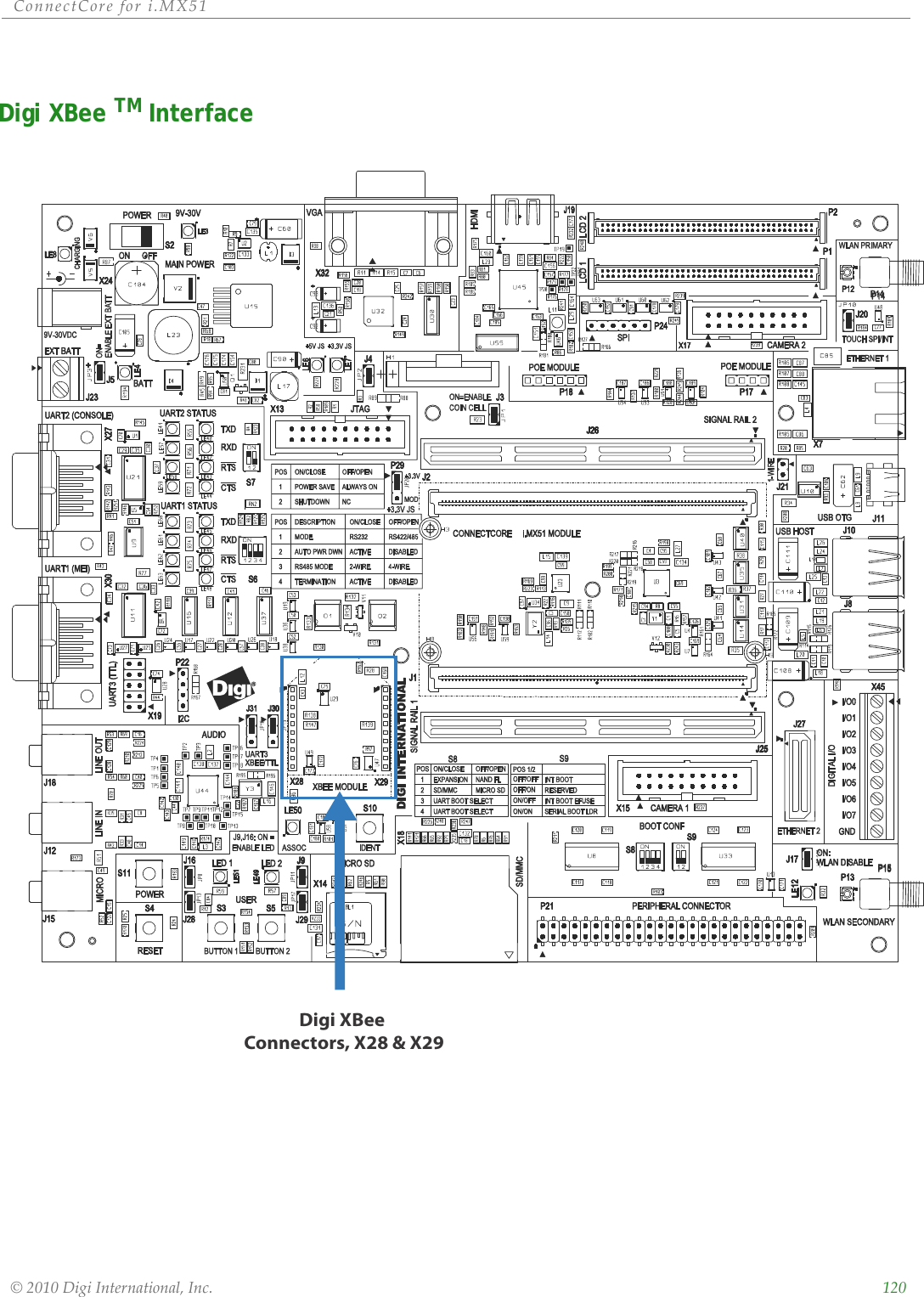
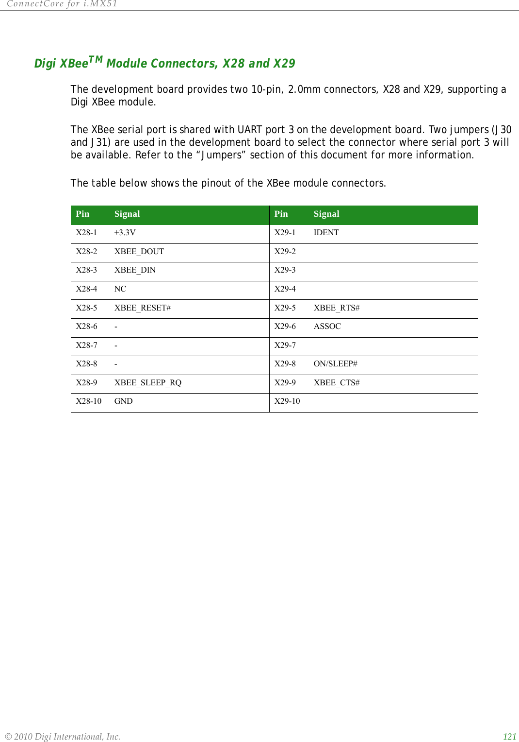
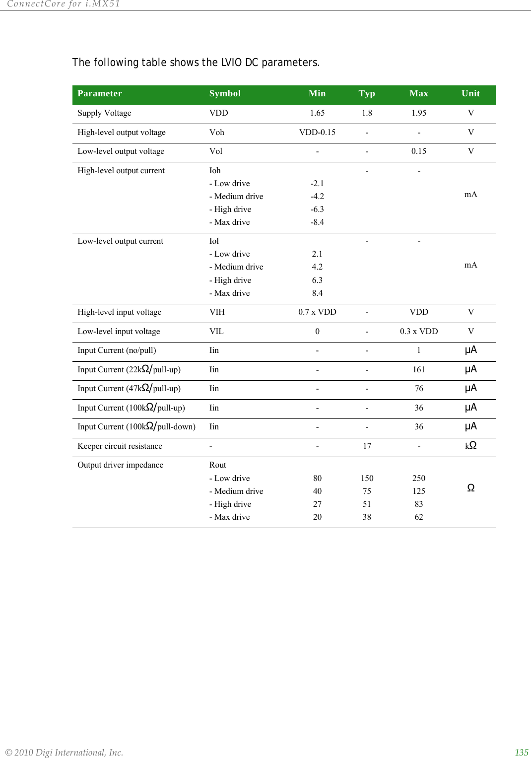
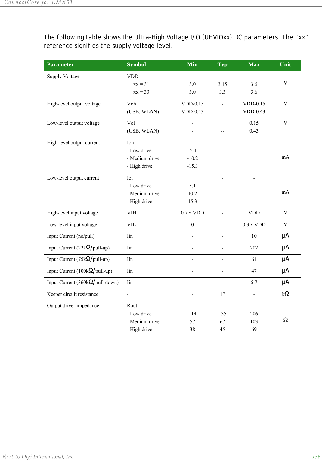
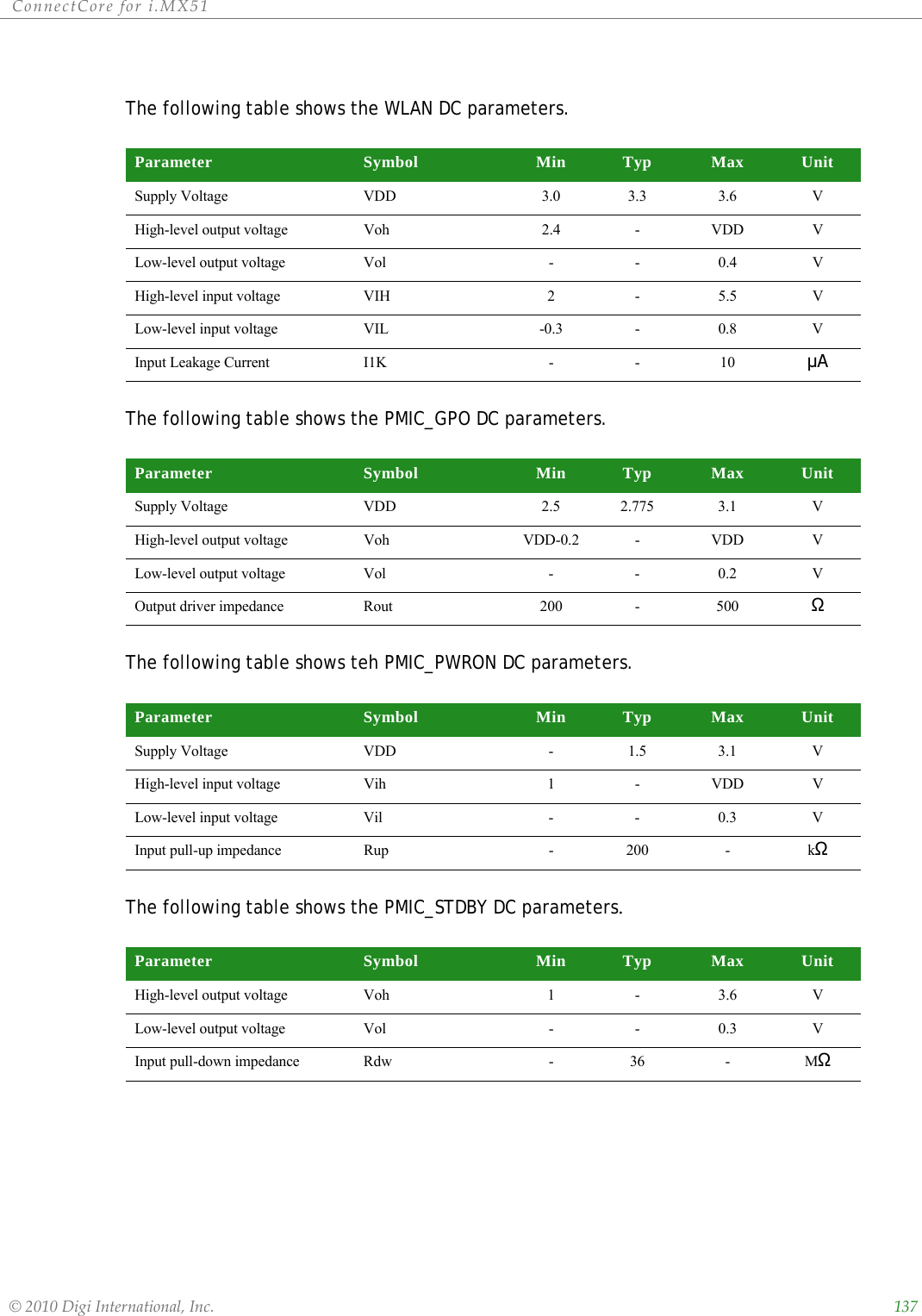
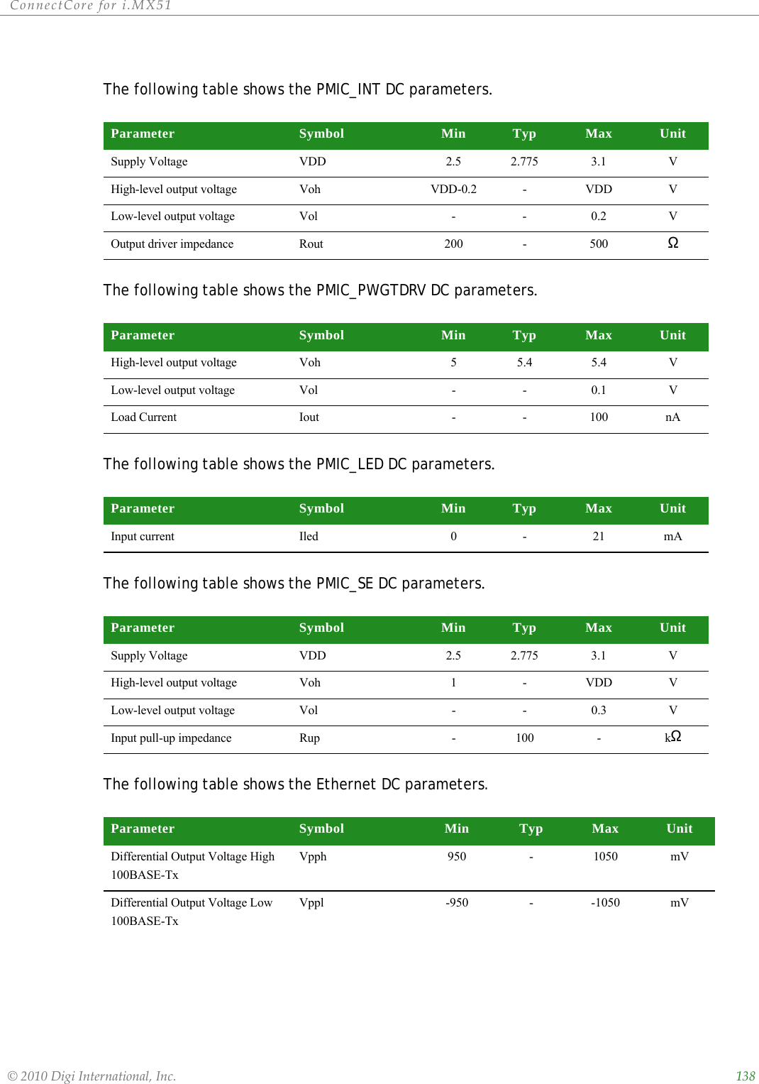
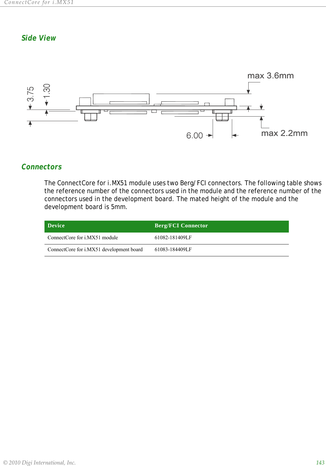
User Manual Part4